1
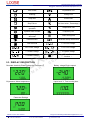
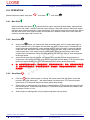
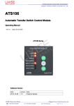
LXC706 Series Genset Controller Dongguan Tuancheng Automation Equipment Co.,Ltd. LXC706 Genset Controller User Manual Ver1.1 Date: 2014/03/20 LXC706 SERIES Software version Date 2013-05-10 2014-03-20 Versio n 1.0 1.1 Note Original release. Added USB interface for directly connecting to PC. Dongguan Tuancheng Automation Equipment Co.,Ltd. LXC706 Product User Manual : +86-769-33263276 : F:+86-769-23166296 : www.lixise.com Page 1 of 16 LXC706 Series Genset Controller Dongguan Tuancheng Automation Equipment Co.,Ltd. Contents 1. SUMMARY.............................................................................................................................................................. 3 2. FEATURES............................................................................................................................................................. 3 3. PERFORMANCE....................................................................................................................................................3 4. SPECIFICATION.................................................................................................................................................... 4 5. DISPLAY SYMBOL AMD OPERATION............................................................................................................. 5 5.1. PUSH BUTTON...........................................................................................................................................5 5.2. LED ICON.................................................................................................................................................... 5 5.3. DISPLAY DESCRIPTION.......................................................................................................................... 6 5.4. OPERATION................................................................................................................................................7 5.4.1. Man Start .................................................................................................................................. 7 5.4.2. Auto State ................................................................................................................................. 7 5.4.3. Stop State ................................................................................................................................. 7 6. ALARM.....................................................................................................................................................................8 7. PARAMETERS TABLE(ONLY ADJUST VIA PC).............................................................................................9 7.1. PARAMETER SETTING LIST (TABLE I)................................................................................................9 7.2. PROGRAMMABLE OUTPUT (TABLE 2)..............................................................................................12 7.3. PROGRAMMABLE INPUT (ACTIVE WHEN CONNECT GND (B-) (TABLE 3)............................. 12 7.4. SENSOR SELECT (TABLE 4)................................................................................................................12 8. CONDITIONS OF CRANK DISCONNECT...................................................................................................... 13 9. PARAMETERS SETTING.................................................................................................................................. 14 10. TERMINAL.......................................................................................................................................................... 15 11. CASE DIMENSIONS.........................................................................................................................................15 12. TYPICAL CONNECTIONS...............................................................................................................................16 13. PRODUCT PACKAGING..................................................................................................................................16 Dongguan Tuancheng Automation Equipment Co.,Ltd. LXC706 Product User Manual : +86-769-33263276 : F:+86-769-23166296 : www.lixise.com Page 2 of 16 LXC706 Series Genset Controller Dongguan Tuancheng Automation Equipment Co.,Ltd. 1. SUMMARY The Module LXC706 is an small Automatic Engine Control Module. It selects 3 kinds of working state(Manual, Auto, Stop), can pass panel light touch buttons artificially start/stop genset, also can through remote start signal input automatic starting generator, and can detect fault (low oil pressure, high water temperature, emergency stop alarm, over speed) automatically disconnect fuel relays and stop electromagnet to electric suction close. Panel LED indicator fault state, provide real and effective fault alarm signal. 2. FEATURES Emerald green backlight, generator parameters are clearly visible during the day and night. LCD icon display alarm, alarm information is visual, universal. On the LCD digital display a variety of generator parameters. The PC panel with durable, waterproof. The control panel, easy realization of generator start stop, reduce the user connection. All parameters can be set on the panel, convenient debugging and maintenance. Set all the configuration parameters and monitoring computer through USB connection. Ultra small size, suitable for small generator, intelligent control is particularly suitable for small gasoline generator. Equipped with a shockproof rubber ring, can achieve waterproof and shockproof panel. Install the assembly, flame retardant ABS shell, pluggable terminal, embedded installation, compact structure, convenient installation. 3. PERFORMANCE The power supply a wide range (8~35) VDC, can adapt different starting battery voltage environment. The microprocessor as the core, for the LCD screen display icon symbols, light touch keys. With low oil pressure, high water temperature, over speed, and emergency stop, start failures and so on protection and instructions. Can detect and display of power are: power voltage V, power frequency Hz, engine temperature ºC, oil pressure kPa, speed rpm, total running time H, the battery voltage V, fuel level%. voltage of the generator, battery voltage, speed, temperature, pressure, liquid level sensor threshold can be set, can achieve the following alarm or warning: low oil pressure, water temperature, cylinder temperature high, speeding, less speed, emergency stop, failure to start, stop, failure of power voltage is too high, too low, power frequency is too high or too low, the battery voltage is too high low, low fuel level. With idle speed control and ETS solenoid function. Dongguan Tuancheng Automation Equipment Co.,Ltd. LXC706 Product User Manual : +86-769-33263276 : F:+86-769-23166296 : www.lixise.com Page 3 of 16 LXC706 Series Genset Controller Dongguan Tuancheng Automation Equipment Co.,Ltd. With 3 working state: manual, automatic, stop. Through the software setting of controllers can be set to the engine controller (not choose the power voltage input), suitable for control of pump unit. Panel with a red light emitting diode (LED) display and alarm status. A variety of temperature, pressure, oil level sensor can be used directly, and can custom parameters: Temperature, pressure sensor, respectively, and temperature, pressure alarm in parallel, in providing the digital quantity at the same time increase the level of protection. Many successful starting condition (rotational speed sensor, oil pressure, power generation) can choose. Four fixed relay output( fuel oil output, starter output, to stop the output, Idle speed output). A programmable output, can be set to public alarm output, stop failure output,preheating output or idle speed control output function. Allow the user to change the setting of parameters, and memory in the internal FLASH memory, will not be lost in the system when the power is off, the controller from the front panel of the controller. All the parameters can be adjusted, or through the USB interface by the PC machine USB power supply controller, through monitoring software for parameter setting. 4. SPECIFICATION project content Working Voltage DC8. 0V to 35. 0V, Continuous Power Supply Overall Consumption standby mode: 12V:0.3W 24V:0.4W working: 12V:1W 24V:1.1W AC voltage Input Single phase 2 Wire 15V AC - 360 V AC (ph-N) Alternator Frequency 50/60Hz Speed Sensor Voltage 1V --24V(effective value) Speed Sensor Frequency maximum 10kHz The maximum total run time 99999.9 hours (After the decimal point is 1/10 hours,Six minutes once changes) Start Relay Output 1Amp DC28V B+ power supply Fuel relay output 1Amp DC28V B+ power supply Shutdown relay output 1Amp DC28V B+ power supply Idle speed relay output 1Amp DC28V B+ power supply Programmable relay output 1Amp DC28V B+ power supply Switch input port After B - effective Overall Dimensions 97mm x 78mm x 44mm Panel Cutout 78mm x 66mm Dongguan Tuancheng Automation Equipment Co.,Ltd. LXC706 Product User Manual : +86-769-33263276 : F:+86-769-23166296 : www.lixise.com Page 4 of 16 LXC706 Series Genset Controller Dongguan Tuancheng Automation Equipment Co.,Ltd. Working Conditions Temperature:(-25~+70)ºC Relative humidity:(20~90)% Storage Conditions Temperature:(-30~+80)ºC Protection Level IP55:When waterproof rubber seal installed between the controller and panel fascia IP42:When waterproof rubber seal is not installed between the controller and panel fascia Insulation Intensity Object:input/output/power Quote standard:IEC688-1992 Test way:AC1.5kV/1min leakage current:1mA Weight 0.13kg 5. DISPLAY SYMBOL AMD OPERATION 5.1. PUSH BUTTON Symbol Defined Description Manual start button Push this button, generator will start, and the module comes into manual state Auto state button Push this button, the module comes into auto state LCD page button/confirm button Push this button, generator will stop, and the module comes into stop state. In the standby mode, if long pressing the button for 3 seconds all LED lights Change the page display, used for LCD and can move the cursor in the parameter Settings and confirm set information Alarm light When an alarm occurs, exhibit of lanterns flicker Stop button 5.2. LED ICON Symbol Defined Defined High Temperature Automatic state Low Oil Press Stop state Over Speed Manual states Under speed Generator voltage Emergency Stop Battery voltage High voltage Amount of fuel Low voltage Speed units (rpm/minute) Dongguan Tuancheng Automation Equipment Co.,Ltd. LXC706 Product User Manual : +86-769-33263276 Symbol : F:+86-769-23166296 : www.lixise.com Page 5 of 16 LXC706 Series Genset Controller Dongguan Tuancheng Automation Equipment Co.,Ltd. Over Crank Oil pressure unit Warning Voltage unit Stop alert Current unit Stop Failure Fuel level units ( Percentage ) Rotation during normal operation Temperature unit flywheel tooth number Frequency unit Battery voltage is abnormal Total running time External alarm Parameter setup instructions Low fuel level L1-L2 Line voltage L2-L3 Line voltage L3-L1 Line voltage L1 Phase voltage L2 Phase voltage L3 Phase voltage Panel lock( Close button function ) 5.3. DISPLAY DESCRIPTION Generate electricity:Phase voltage Ua,Frequency F Battery voltage,Engine speed Oil pressure,Water temperature Liquid level %, Total running time Parameter Settings Dongguan Tuancheng Automation Equipment Co.,Ltd. LXC706 Product User Manual : +86-769-33263276 : F:+86-769-23166296 : www.lixise.com Page 6 of 16 LXC706 Series Genset Controller Dongguan Tuancheng Automation Equipment Co.,Ltd. 5.4. OPERATION Module has three states: stop state 、man state 、auto state . 5.4.1. Man Start When push Man start button ,preheat will first output, and start preheat delay, when preheat delay is end, fuel output 1 second, preheat output will stop, and crank output is start.Here engine will start, when crank successfully, crank output stop. Then engine comes into the safe time. When the safe time is end, then engine comes into the idle time. When the safe time is end, then idle output is out and engine will run at full tilt. 5.4.2. Auto State When push button, the module will enter automatic state. Here if remote start input is active (connect to B-), the engine will start after the delay of start engine. Preheat will first output, and start preheat delay, when preheat delay is end, fuel output 1 second, preheat output will stop, and crank output is start. Here engine will start, when crank successfully, crank output stop. Then engine enter the safe delay. When the safe delay is end, then engine enter the idle delay. When the safe delay is end, then idle relay is close and genset raise high speed. When remote start input is inactive, the engine enter the idle process after the delay of engine stop, idle relay disconnect, fuel relays output after the idle delay, ETS solenoid output, genset will automatically stop, ETS solenoid disconnect when genset stop steady. 注:在起动间隔延时过程中,燃油输出断开,起动间隔延时开始 3 秒后,预热和得电停机输 出,起动间隔延时结束后,得电停机输出断开,燃油输出,预热输出在起动前断开。(此段无 英文翻译) 5.4.3. Stop State Push the button when engine is running, the button beside led will lighten, enter idle process, idle relay disconnect, idle delay ended, fuel disconnect, ETS solenoid output, genset stop, ETS solenoid disconnect when genset stop steady. When engine is waiting state, push button 1 second above, ETS solenoid will output and all led will be Lighten. Loosen the stop buttons, ETS solenoid output disconnect instantly, and test lamps function is over. When engine is waiting state, only emergent stop alarm can be check. Dongguan Tuancheng Automation Equipment Co.,Ltd. LXC706 Product User Manual : +86-769-33263276 : F:+86-769-23166296 : www.lixise.com Page 7 of 16 LXC706 Series Genset Controller Dongguan Tuancheng Automation Equipment Co.,Ltd. 6. ALARM Low Oil Pressure: check after the safe delay, the duration of 5 seconds above, the module will alarm and stop engine. High Temperature:check after the safe delay, the duration of 10 seconds above, the module will alarm and stop engine. Low Fuel Level: When the fuel level is consistently below the preset value of 10 seconds, and issuing fuel level is too low signal, this value is only a warning will not stop. Over speed: check after the preheat delay, the duration of 2 seconds above, the module will alarm and stop engine. Under speed: check when engine run at full tilt, the duration of 15 seconds above, the module will alarm and stop engine. Over Crank: when engine crank fail over the times of configure, the module will alarm and stop engine. Stop Failure: when engine is stop fail, the module will warn. Battery over voltage: The DC supply has risen above the high volts setting level for the duration of the high battery volts 20 seconds. Battery under voltage: The DC supply has low above the under volts setting level for the duration of the low battery volts 20 seconds. Emergency Stop: When emergency stop input, ETS solenoid stop immediately output, and then fuel disconnect, preheat and start signal emit emergency stop alarm signal. Gen Over Voltage: When the continuous sampling voltage higher than the preset value, at the end of the abnormal delay, signal generator voltage is too high, outage alarm at the same time. Gen Under Voltage: When sampling the voltage is lower than the preset value continuously, at the end of the abnormal delay signal generator voltage is too low, outage alarm at the same time. Gen Over Frequency: When the sampling frequency for 10 seconds after the signal generator frequency is too high, outage alarm at the same time. Gen Under Frequency: When the sampling frequency for 2 seconds after the signal generator frequency is too low, outage alarm at the same time. Common Alarm: when any alarm or warn is appear, this alarm will active. When the over speed, under speed, high temperature, low oil pressure, emergency stop, no generator, crank failure, stop failure alarm, battery over voltage, battery under voltage, common alarm LED illuminate, and common alarm output. Dongguan Tuancheng Automation Equipment Co.,Ltd. LXC706 Product User Manual : +86-769-33263276 : F:+86-769-23166296 : www.lixise.com Page 8 of 16 LXC706 Series Genset Controller Dongguan Tuancheng Automation Equipment Co.,Ltd. 7. PARAMETERS TABLE(ONLY ADJUST VIA PC) 7.1. PARAMETER SETTING LIST (TABLE I) Set the content as follows: NO. Parameter Range Default Description P00 Start delay (0-3600s) 1s P01 Stop delay (0-3600s) 1s P02 Number of Crank (1-9) 3 Numbers of crank cycles. It’s the delay from remote start signal is active or mains is failure, to start generator. It’s the delay from remote start signal is inactive or mains is normal, to stop generator. P03 Preheat time (0-300)S 0s This timer dictates the duration that the pre-heat output will be active before an attempt is made to start the engine. Once this timer has expired cranking will commence. P04 Cranking time (1-60)S 8s This is the maximum amount of time that the module will energize the starter motor for during starting attempts once the starter has engaged. P05 Crank rest time (3-60)S 10s This is the amount of time the module will wait for between start attempts.This is to allow the starter motor to cool and the starter batteries to recover. P06 Safe running time (1-60)S 10s This timer dictates how long the module will ignore the Low oil pressure, High Engine Temperature, Under speed, Under volts and any other inputs configured as active from safety on. P07 Start idle time (0-3600)S 0s This is the amount of time that the start Idle speed is held active.These allow the engine to hold low speed. (0-3600)S 10s (0-3600)S 10s P09 Warming up delay Cooling delay P10 Stop idle time (0-3600)S 0s P11 ETS solenoid hold (0-120)S 20s P08 This is the amount of time that the stop Idle speed is held active. These allow the engine to hold low speed. This timer is used if the unit is configured to operate an Energize to stop engine. It dictates the duration that the ETS output will remain active after the module has detected the engine has come to rest. If the ETS output is not configured, this timer will still operate, preventing an immediate restart. P12 Fail to stop delay (0-120)S 0s Once the module has given a shutdown signal to the engine it expects the engine to come to rest. It monitors the Oil pressure and speed sensing sources and if they still indicate engine movement when this timer expires a ‘Fail to stop’ alarm signal is generated. P13 Flywheel Teeth (100-300) 118 Tooth number of the engine, for judging of starter crank disconnect conditions and inspecting of engine speed. See the installation instructions. P14 Poles (2-16) 4 P15 Gen Abnormal Delay (0-20.0)s 10.0s Dongguan Tuancheng Automation Equipment Co.,Ltd. LXC706 Product User Manual : +86-769-33263276 The alarm delay of generator over voltage and under voltage. : F:+86-769-23166296 : www.lixise.com Page 9 of 16 LXC706 Series Genset Controller Dongguan Tuancheng Automation Equipment Co.,Ltd. P16 P17 P18 P19 P20 P21 P22 P23 P24 P25 P26 When generator voltage has exceed the set value and the “Gen abnormal delay” has expired, Gen Over (30-620)V 264V Voltage is active. When set the value as 620V, the controller does not detect over voltage signal. When generator voltage has fallen below the set value Generator Under and the “Gen abnormal delay” has expired, Gen Under (30-620)V 196V Voltage Voltage is active. When set the value as 30V, the controller does not detect under voltage signal. When engine speed has exceed the set value for 2s, Over Speed (0-6000)RPM 1710RPM Over Speed is active. It will initiate a shutdown alarm signal. When engine speed has fallen below the set value for Under Speed (0-6000)RPM 1200RPM 10s, Under Speed is active. It will initiate a shutdown alarm signal. When generator frequency has exceed the set value Over Frequency (0-75.0)Hz 57.0Hz for 2s, Over Frequency is active. It will initiate a shutdown alarm signal. When generator frequency has fallen below the set Under (0-75.0)Hz 45.0Hz value but Not equal to 0 for 10s, Under Frequency is Frequency active. It will initiate a shutdown alarm signal. During generator is normal running, when alternator Charge Alt D+(WL) voltage has fallen below the set value and Failure (0-30.0)V 6.0V remains for 5s, It will initiate a shutdown alarm signal. (Warning) (Return value is 1V). When battery voltage has exceeds the set value and Battery Over remains for 20s, It will initiate a warning alarm signal. Voltage (12.0-40.0)V 33.0V Only warning and not to shutdown the generator. (Warning) (Return value is 1V). When battery voltage has fallen below the set value Battery Under and remains for 20s, It will initiate a warning alarm Voltage (4.0-30.0)V 8.0V signal. Only warning and not to shutdown the (Warning) generator.(Return value is 1V). Gen Over Voltage High Temperature Low Oil Pressure P27 Low fuel P28 Configurable output (80-140)ºC (0-400)kPa (0-100)% (0-6) 98 When the temperature value of the external temperature sensor exceeds the set value, high temperature signal is sent. Detecting only after safety on delay is over. If the set value is 140, high temperature signal will not be sent (this only concerns external temperature sensor, not high temperature signal via configuration. input port). 103kPa When the external pressure sensor value falls below this set value, low oil pressure signal is sent. Detecting only after safety on delay is over. If the set value is 0, low oil pressure signal will not be sent (this only concerns pressure sensor and does not concern low oil pressure warning signal via configurable input port). 10% When the liquid level of the external liquid level sensor is smaller than this value and lasts 10 seconds, the signal level is too low, Only warning and not to shutdown the generator. 0 Dongguan Tuancheng Automation Equipment Co.,Ltd. LXC706 Product User Manual : +86-769-33263276 0:Not used 1:Common alarm 2:Energized To Stop output 3:Idle control : F:+86-769-23166296 : www.lixise.com Page 10 of 16 LXC706 Series Genset Controller Dongguan Tuancheng Automation Equipment Co.,Ltd. P29 Digital input type P30 P31 P32 P33 P34 P35 P36 P37 P38 P39 P40 P41 P42 P43 (0-8) Digital input (0-20)s units: activation delay 0.1s 0 4:Preheat control 5:Close Gens 6:Reserved 0:not used 1:High temperature downtime input 2:Low oil pressure shutdown input 3:Low fuel warning input 4:External shut down input 5:High temperature thermal shutdown 6:Reserved 7:Reserved 8:Fuel level sensor 2.0s 0:Freq 1:Engine speed 2:speed +Electricity generation 3:Oil pressure 4:Oil pressure + Electricity generation Crank (0-8) 6 Disconnect 5:Oil pressure + speed 6:Oil pressure + speed + Electricity generation 7:Charge D+ 8:Oil pressure + speed + Electricity generation 9:Invalid combination In the process of cranking, when the gens frequency Freq disconnect (10.0-30.0)Hz 14.0Hz exceeds this value, the starter will be separated. Disconnect When engine speed higher than the set value, starter (0-3000)RPM 360RPM Engine Speed will be disconnected. Disconnect Oil When generator oil pressure higher than the set value, (0-400)kPa 200kPa Pressure starter will be disconnected. D+ When generator D+ higher than the set value, starter (3.0-32.0)V 8.0V Disconnect will be disconnected. Temp. Sensor (0-10) 3 VDO120 ºC Curve Oil Pressure (0-9) 3 VDO0-10BAR Sensor Curve not used. (Using the fuel level sensor will switch input Fuel sensor (0-5) 0 port is set to unused) Temperature 0: Never (temperature sensor will show “+++”); (0-2) 0 Sensor Open 1:Warn; 2:Shutdown Oil Pressure 0: Never (temperature sensor will show “+++”); (0-2) 0 Sensor Open 1:Warn; 2:Shutdown Fuel sensor open 0: Never (temperature sensor will show “+++”); (0-1) 0 1:Warn; Device ID 1-247 1 Power On Mode 0-2 0 0:Stop Mode 1:Auto mode 2:Manual Mode P44 technician password 0-9999 0000 P45 operator password 0-9999 1111 Dongguan Tuancheng Automation Equipment Co.,Ltd. LXC706 Product User Manual : +86-769-33263276 : F:+86-769-23166296 : www.lixise.com Page 11 of 16 LXC706 Series Genset Controller Dongguan Tuancheng Automation Equipment Co.,Ltd. 7.2. PROGRAMMABLE OUTPUT (TABLE 2) No. 0 ITEM Not Used 1 Common Alarm 2 ETS Control 3 4 5 6 Idle Control Preheat Control Close Generator Reserved Description When selected, the output port is not output. Includes all stop alarm and warning alarm, when only warning alarm input, this alarm is not self-locking, when outage alarm occurs, the alarm self-locking, until the alarm is reset. Used for engines with ETS electromagnet. Pull in when stop idle is over and pull out when set“ETS delay”is over. Used for engine which has idles.Pull in before starting and pull out after into hi-speed warming; Pull in during stopping idle mode and pull out after shutdown completed. Before the boot is closed, power is disconnected before starter. Generator load conditions are ripe for action. 7.3. PROGRAMMABLE INPUT (ACTIVE WHEN CONNECT GND (B-) (TABLE 3) No. 0 1 2 3 ITEM Not Used Aux High Temp Aux Low OP Low fuel External stop generators 4 Description In after the success of the generator starting, if the signal is effective, generator alarm and shutdown immediately If the signal is effective, warn only, not shutdown If the signal is effective, warn only, not shutdown When this signal is effective and normal operation, If the temperature is too high, controller high-speed When cooling delay until after the downtime; When this signal temperature is too is invalid, If there is high temperature, the controller high downtime directly to the high-speed stop. Reserved Reserved Fuel level sensor Sensor selection (table 4) Switch input 5 6 7 8 7.4. SENSOR SELECT (TABLE 4) No. 1 ITEM Content 0 Not used 1 Digital input low effective 2 Digital input high effective Temperature 3 VDO 120℃ sensor 4 CURTIS 5 VOLVO-EC 6 DATCON 7 SGX 8 SGD 9 SGH 10 PT100 Digital input is the switch signal, can choose low level or high level, grounding is low level, suspend in midair is the high level, not plugged into a power supply for the Cathode. Defined resistive range is 0-999.9 Ω, the factory default is SGD sensor. Dongguan Tuancheng Automation Equipment Co.,Ltd. LXC706 Product User Manual : +86-769-33263276 Description : F:+86-769-23166296 : www.lixise.com Page 12 of 16 LXC706 Series Genset Controller Dongguan Tuancheng Automation Equipment Co.,Ltd. 2 3 Pressure sensor Fuel level sensor 0 Not used 1 Digital input low effective 2 Digital input high effective 3 VDO0-10BAR 4 CURTIS 5 VOLVO-EC 6 DATCON?10BAR 7 SGX 8 SGD 9 SGH 0 Not used 1 Digital input low effective 2 Digital input high effective 3 VDO0-180ohm 4 SGD 5 SGH Digital input is the switch signal, can choose low level or high level, grounding is low level, suspend in midair is the high level, not plugged into a power supply for the Cathode. Defined resistive range is 0-999.9 Ω, the factory default is SGD sensor. Digital input is the switch signal, can choose low level or high level, grounding is low level, suspend in midair is the high level, not plugged into a power supply for the Cathode. Defined resistive range is 0-999.9 Ω,the factory default is no sensor. In setting fuel level sensor type when, Should put the programmable input port type is set to 0, then set the fuel level sensor type. 8. CONDITIONS OF CRANK DISCONNECT Pictured above,select the desired options,can be selected or not selected There are 4 conditions to make starter disconnected with engine,that is,speed sensor, generator frequency ,Charge D + and engine oil pressure. They all can be used separately. We recommend that engine oil pressure should be using with speed sensor and generator frequency together, in order to make the starter motor is separated with engine immediately and can check crank disconnect exactly. Speed sensor is the magnetic equipment which be installed in starter for detecting flywheel teeth. When set as speed sensor, must ensure that the number of flywheel teeth is as same as setting, otherwise,“over speed stop”or“under speed stop”may be caused. If genset without speed sensor, please don’t select corresponding items, otherwise, “start fail”or“loss speed signal”maybe caused. If genset without oil pressure sensor, please don’t select corresponding items. If not select generator in crank disconnect setting, controller will not collect and display the relative power quantity (can be used in water pump set);if not select speed sensor in crank disconnect setting, the rotating speed displayed in controller is calculated by generator frequency and number of poles. If the generator without magnetoelectric sensor and Oil pressure sensor,the“Charger D+”is optional as a starter motor separation conditions.It is recommended to select“Oil Pressure+ Charger D+”for safety. Dongguan Tuancheng Automation Equipment Co.,Ltd. LXC706 Product User Manual : +86-769-33263276 : F:+86-769-23166296 : www.lixise.com Page 13 of 16 LXC706 Series Genset Controller Dongguan Tuancheng Automation Equipment Co.,Ltd. 9. PARAMETERS SETTING 1) The controller in standby mode simultaneously press the and ,entering the password input interface ( following figure), When the first digit flashing, enter the password 0000; 2) press the numerical plus 1, press the value press the Numerical minus 1, Set the correct numerical change; 3) Set the second bit to fourth bit digital in accordance with the above method; 4) If the input the correct password to enter parameter setting interface (following figure), Displays the current settings of the serial number and parameter, press the the set options flip up, press set options flip down; 5) press the enter the parameter setting state, the first digit flashing, set of numerical methods with the same password input method. Password input interface: Parameter Settings interface: Matters needing attention: 1) Please change the controller parameters when generator is in standby mode only (e. g. Crank disconnect conditions selection, digital input, digital output, various delay), otherwise, shutdown and other abnormal conditions may occurs. 2)When set each parameter, must be within the allowed range, otherwise will not be able to change the parameters. 3) Over voltage set value must be higher than under voltage set value, otherwise the controller will not save the data. 4)Over speed set value must be higher than under speed set value, otherwise the controller will not save the data. 5) Please set the generator frequency value as low as possible when cranking, in order to make the starter be separated quickly as soon as possible. 6)Set the serial number with reference to the front “7.1 Parameter setting list (Table I)”. 7)In setting fuel level sensor type when, the programmable output type is set to 0, set the fuel level sensor type again. ﹡NOTE 1:In the process of setting up, any time button will interrupt parameter settings. ﹡NOTE 2:In manual mode, startup success condition configuration:(2 magnetic sensor+generate electricity) or (5 generate electricity + magnetic sensor +oil pressure), power frequency and speed is not zero, press the start button and flip keys at the same time (0.5s), controller according to the power frequency and generator series automatic generator teeth. Dongguan Tuancheng Automation Equipment Co.,Ltd. LXC706 Product User Manual : +86-769-33263276 : F:+86-769-23166296 : www.lixise.com Page 14 of 16 LXC706 Series Genset Controller Dongguan Tuancheng Automation Equipment Co.,Ltd. 10. TERMINAL Terminal 1(B-): connect to the cathode of battery. Terminal 2 (B+): connect to the anode of battery. Terminal 3 (Em. stop input): emergent stop input, connect to (B+) is active. Terminal 4 (Fuel Output): Fuel Output, (B+,1A). Terminal 5 (Start Output): Start Output, (B+, 1A). Terminal 6(Remote Start Input): Remote Start Input, connect to (B-) is active. Terminal 7(Configurable Input):Programmable input port, By setting the input signal switch quantity or fuel level sensor signal, switch input connect to (B-) is active. Terminal 8(LOP Input): Low oil pressure input, switch input connect to (B-) is active. Terminal 9(HWT. Input): High temperature input,switch input connect to (B-) is active. Terminal 10(L)、11(N):Alternator Input. Terminal 12(Idle Output):Idle speed control output port (B+,1A). Terminal 13(Stop Output):ETS output (B+ ,1A). Terminal 14(Configurable Output3):Configurable output, (B+, 1A). Terminal 15( D+):Connect to charging starter’s D+ terminal. If there is no this terminal, then be hang up. Terminal 16 (Magnetic pickup):Magnetic head signal input,suggest using the shielded wire. USB Interface:Controller directly through the USB line connected to the computer for parametric programming. 11. CASE DIMENSIONS (HOLE: 78mm*66mm) Dongguan Tuancheng Automation Equipment Co.,Ltd. LXC706 Product User Manual : +86-769-33263276 : F:+86-769-23166296 : www.lixise.com Page 15 of 16 LXC706 Series Genset Controller Dongguan Tuancheng Automation Equipment Co.,Ltd. 12. TYPICAL CONNECTIONS 13. PRODUCT PACKAGING This product should be following sets: (1) 1 piece of controller model LXC706; (2) 2 piece of fixed cards; (3) 1 piece of product certificate; (4) 1 piece of product manual. Tel:8+86-769-33263276 Fax:+86-769-23166296 http://dgfeirui.en.alibaba.com http://www.lixise.net E-mail:sales@ smartgenset.com Add: 18# Chashang industrial zone, WenTang Road Dongguan City, Guangdong, China Dongguan Tuancheng Automation Equipment Co.,Ltd. LXC706 Product User Manual : +86-769-33263276 Dongguan Tuancheng Automation Equipment Co.,LTD. : F:+86-769-23166296 : www.lixise.com Page 16 of 16