1
Menntor X7
Modular Patient Monitors
USER MANUAL
DDM-781-001
Rev.C Nov. 2014
Conformity according to the Council Directive 93/42/EEC concerning Medical Devices
Manufacturer’s Name
:
Mennen Medical Ltd.
4 Hayarden Street, Yavne, 8122804
P.O. Box 102, Rehovot, 7610002, Israel
Tel.: +972-8-9323333
Fax: +972-8-9328510
European Representative
Charter-Kontron Limited
Unit 18 Avant Business Centre
21 Denbigh Road
Milton Keynes
MK1 1DT England
Tel.: 01908 646070
Fax: 01908 646030
:
US Representative:
Mennen Medical Corp.
290 Andrews Road
Feasterville-Trevose, PA 19053-3480
Phone 215 259-1020
Fax 215 357-2010
Publication No. DDM-781-001 Ver. 7.0
Revision C November 2014
Copyright © Mennen Medical Ltd. 2014. All RIGHTS RESERVED
Registered trademarks are the intellectual property of their respective holders.
TABLE OF CONTENTS
Table of Contents
Section 1
Introduction
Chapter 1:
What You Should Know
Training ..................................................................................................................................................
Service ....................................................................................................................................................
Prescription Notice .................................................................................................................................
User Capability ......................................................................................................................................
General Description ...............................................................................................................................
Menntor X7 Part Numbers .....................................................................................................................
Manual Structure ....................................................................................................................................
Changes in Default Configuration .........................................................................................................
Intended Use ..........................................................................................................................................
Compliance ............................................................................................................................................
Network – Mennen-Net .........................................................................................................................
1-1
1-1
1-1
1-1
1-2
1-2
1-3
1-4
1-4
1-5
1-6
Chapter 2:
Warnings and Precautions
Power Failure .........................................................................................................................................
Minimizing Electrosurgical Interference ...............................................................................................
Electrical Shock Hazard .........................................................................................................................
Connection of Other Medical Devices ...................................................................................................
Explosion Hazard ...................................................................................................................................
Environmental Status .............................................................................................................................
Monitor Storage .....................................................................................................................................
Use of Manual ........................................................................................................................................
Responsibility .........................................................................................................................................
Labeling .................................................................................................................................................
Electrode and Transducer Protection .....................................................................................................
General Use of Accessories ...................................................................................................................
Disposal of Monitors and Accessories ...................................................................................................
2-1
2-2
2-3
2-3
2-4
2-4
2-4
2-4
2-4
2-5
2-7
2-8
2-8
Chapter 3:
System Description
Overview ................................................................................................................................................ 3-1
System Features and Capabilities .......................................................................................................... 3-2
Mennen Medical®
i
Menntor X7® Operating Manual
System Specifications ............................................................................................................................ 3-7
Chapter 4:
Installation and Setup
Unpacking and Inspection ..................................................................................................................... 4-1
Setting Up the System ........................................................................................................................... 4-1
Installation Procedures .......................................................................................................................... 4-1
Chapter 5:
Maintenance and Cleaning
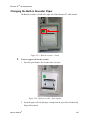
Cleaning the Menntor X7 Bedside Monitor ..........................................................................................
Calibration and Preventive Maintenance ...............................................................................................
Battery Conditioning .............................................................................................................................
Equipment End of life ...........................................................................................................................
5-1
5-2
5-3
5-3
Chapter 6:
Controls and Functions
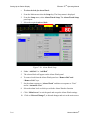
Power On ............................................................................................................................................... 6-1
AC Operation ......................................................................................................................................... 6-2
Power Interruptions ............................................................................................................................... 6-2
Main Screen Display Features ............................................................................................................... 6-3
Main Processing Unit ............................................................................................................................ 6-8
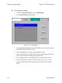
Working With Menus and Panels ........................................................................................................ 6-12
Section 2
Patient Monitoring Procedures
Chapter 7:
Setting Up the Patient Display
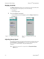
Display Controls .................................................................................................................................... 7-2
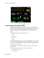
Cardio Respiratory Graph (CRG) .......................................................................................................... 7-5
Remote View ......................................................................................................................................... 7-9
Chapter 8:
Alarms
General Features .................................................................................................................................... 8-1
Alarm Notification ................................................................................................................................. 8-2
Alarm Priority ........................................................................................................................................ 8-4
Setting Up Alarms ................................................................................................................................. 8-6
Alarm Controls ...................................................................................................................................... 8-6
Alarm Status .......................................................................................................................................... 8-9
What To Do When an Alarm Occurs .................................................................................................. 8-10
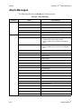
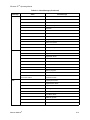
Alarm Messages .................................................................................................................................. 8-12
Chapter 9:
Connecting a Patient to Menntor X7
Patient Preparation ................................................................................................................................. 9-1
Admission, Discharge and Transfer Procedures ................................................................................... 9-1
Setting up Monitoring Profiles ............................................................................................................ 9-20
ii
Mennen Medical®
Menntor X7® Operating Manual
Chapter 10:
Reviewing Patient Data
Trends ................................................................................................................................................... 10-2
ST Watch .............................................................................................................................................. 10-5
Charts ................................................................................................................................................. 10-12
Full Disclosure ................................................................................................................................... 10-15
Overview Panel .................................................................................................................................. 10-21
Event Strips ........................................................................................................................................ 10-23
Reports ............................................................................................................................................... 10-27
Heart Rate Variability - HRV ........................................................................................................... 10-31
Chapter 11:
Performing Clinical
Calculations
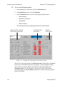
Viewing the Calculation Panels ...........................................................................................................
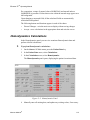
Hemodynamics Calculations ................................................................................................................
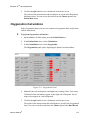
Respiratory Mechanics Calculations ....................................................................................................
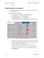
Oxygenation Calculations ....................................................................................................................
Renal Clearance Calculations ..............................................................................................................
11-1
11-3
11-4
11-5
11-6
Chapter 12:
Performing Medication
Calculations
Calculation Formulas ...........................................................................................................................
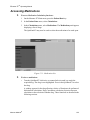
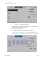
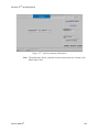
Accessing Medications ........................................................................................................................
Using The Medication Calculation Panels ...........................................................................................
Infusion Rate Calculation .....................................................................................................................
Drug Concentrate Calculation ..............................................................................................................
Injection Amount Calculation ..............................................................................................................
12-1
12-3
12-4
12-4
12-6
12-7
Chapter 13:
Recording Vital Sign Data
Waveform Recording ........................................................................................................................... 13-1
Recording Types .................................................................................................................................. 13-5
Section 3
VITAL SIGNS MONITORING
Chapter 14:
ECG
Overview .............................................................................................................................................. 14-1
ECG Deactivation ................................................................................................................................ 14-1
QRS Detection ..................................................................................................................................... 14-2
ECG LED Indicator ............................................................................................................................. 14-2
Patient Preparation ............................................................................................................................... 14-2
ECG Monitoring Checklist .................................................................................................................. 14-6
ECG Monitoring Procedures ................................................................................................................ 14-6
Setting ECG Leads & Gain Parameters ............................................................................................... 14-8
Setting ECG Alarms ........................................................................................................................... 14-12
Mennen Medical®
iii
Menntor X7® Operating Manual
Setting ECG Report ...........................................................................................................................
Setting ECG Display Options ............................................................................................................
Setting QRS Tone Volume ................................................................................................................
Detecting a Pacemaker ......................................................................................................................
Pacer Alarms .....................................................................................................................................
Setting the Heart Rate Source ............................................................................................................
Selecting a Filter ................................................................................................................................
ECG Recording .................................................................................................................................
ECG Report Printing .........................................................................................................................
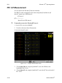
PR / QT Measurement .......................................................................................................................
14-16
14-17
14-18
14-20
14-22
14-23
14-24
14-26
14-26
14-28
Chapter 15:
Arrhythmia
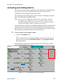
Introduction .........................................................................................................................................
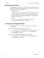
Monitoring Procedures ........................................................................................................................
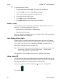
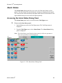
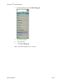
Accessing the Arrhythmia Menu .........................................................................................................
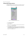
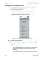
Activating and Setting Alarms ............................................................................................................
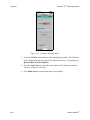
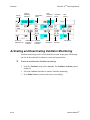
Activating Arrhythmia Monitoring .....................................................................................................
15-1
15-4
15-4
15-5
15-9
Chapter 16:
ST Segment Analysis
Monitoring Procedures ........................................................................................................................
Accessing the ST Menu .......................................................................................................................
Activating ST Monitoring ...................................................................................................................
Setting ST Alarms ...............................................................................................................................
16-2
16-2
16-3
16-3
Chapter 17:
Respiration
Overview ............................................................................................................................................. 17-1
Patient Preparation ............................................................................................................................... 17-1
Monitoring Procedures ........................................................................................................................ 17-2
Setting Respiration Leads and Gain .................................................................................................... 17-3
Setting Respiration Alarms .................................................................................................................. 17-4
Setting Resp Display Options .............................................................................................................. 17-8
Setting the Heart Rate Coincidence Alarm ....................................................................................... 17-10
Activating and Deactivating Respiration Monitoring ....................................................................... 17-12
Chapter 18:
Invasive Blood Pressures (BP)
Overview ............................................................................................................................................. 18-1
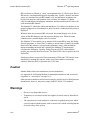
Caution ................................................................................................................................................ 18-2
Warnings .............................................................................................................................................. 18-2
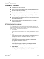
Preparatory Checklist .......................................................................................................................... 18-3
BP Monitoring Procedures .................................................................................................................. 18-3
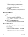
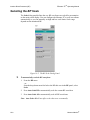
Accessing the BP Menu ....................................................................................................................... 18-4
Zeroing BP Transducers ...................................................................................................................... 18-4
Selecting the BP Scale ......................................................................................................................... 18-6
Setting BP Alarms ............................................................................................................................... 18-7
Setting BP Display Options ............................................................................................................... 18-11
iv
Mennen Medical®
Menntor X7® Operating Manual
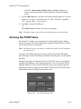
Deriving the PCWP Value ................................................................................................................. 18-13
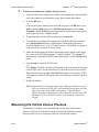
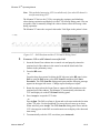
Measuring the Central Venous Pressure ............................................................................................ 18-14
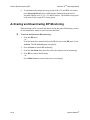
Activating and Deactivating BP Monitoring ..................................................................................... 18-16
Chapter 19:
Cardiac Output (C.O.)
Overview .............................................................................................................................................. 19-1
Preparatory Checklist ........................................................................................................................... 19-2
Measuring Procedures .......................................................................................................................... 19-2
Cardiac Output Measurement .............................................................................................................. 19-5
Cardiac Output Fick Method .............................................................................................................. 19-10
Chapter 20:
Temperature
Overview ..............................................................................................................................................
Preparatory Checklist ...........................................................................................................................
Temperature Monitoring Procedures ...................................................................................................
Setting Temperature Alarms ................................................................................................................
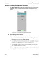
Setting Temperature Display Options ..................................................................................................
Activating Temperature Monitoring ....................................................................................................
Setting Delta Temperature ...................................................................................................................
20-1
20-1
20-2
20-3
20-6
20-7
20-8
Chapter 21:
Non-Invasive Blood Pressure (NIBP)
Overview .............................................................................................................................................. 21-1
Limitations of the Oscillometric Method ............................................................................................. 21-2
Preparatory Checklist ........................................................................................................................... 21-3
Warnings .............................................................................................................................................. 21-3
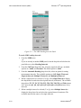
Monitoring Procedures ......................................................................................................................... 21-5
Accessing the NIBP Menu ................................................................................................................... 21-6
Setting Reading Intervals ..................................................................................................................... 21-6
Selecting the Cuff Type ....................................................................................................................... 21-9
Setting NIBP Alarms ......................................................................................................................... 21-10
Setting NIBP Display Options ........................................................................................................... 21-13
Activating NIBP Measuring and Monitoring ..................................................................................... 21-15
Technical Messages ........................................................................................................................... 21-16
Chapter 22:
Pulse Oximetry (SpO2)
Overview .............................................................................................................................................. 22-1
Patient Preparation Checklist ............................................................................................................... 22-2
Monitoring Procedures ......................................................................................................................... 22-5
Accessing the SpO2 Menu ................................................................................................................... 22-6
Setting SpO2 Alarms ........................................................................................................................... 22-6
Setting SpO2 Display Options ........................................................................................................... 22-11
Activating and Setting SpO2 Pulse Tones ......................................................................................... 22-12
Setting SpO2 Response Time ............................................................................................................ 22-14
Activating SpO2 Monitoring ............................................................................................................. 22-15
Masimo Technology .......................................................................................................................... 22-15
Mennen Medical®
v
Menntor X7® Operating Manual
SpO2 Specification ............................................................................................................................ 22-17
Chapter 23:
End Tidal CO2 (EtCO2) Microstream /MicroPod™
Principles of Operation ........................................................................................................................ 23-1
Intended Use ........................................................................................................................................ 23-2
Microstream EtCO2 Circuits ............................................................................................................... 23-3
Using the MicroPod™ ......................................................................................................................... 23-4
Patient Preparation Checklist .............................................................................................................. 23-5
Cautions and Warnings ........................................................................................................................ 23-5
Interfering Gasses ................................................................................................................................ 23-5
Cleaning ............................................................................................................................................... 23-6
Calibration ........................................................................................................................................... 23-6
Sidestream Monitoring for Intubated Patients .................................................................................... 23-6
Sidestream Monitoring of Non-Intubated Patients .............................................................................. 23-7
Intubated Sidestream Monitoring ........................................................................................................ 23-7
Monitoring Procedures ........................................................................................................................ 23-7
Accessing the EtCO2 Menu ................................................................................................................ 23-8
Setting EtCO2 Alarms ......................................................................................................................... 23-9
Setting EtCO2 Display Options ......................................................................................................... 23-12
IPI ...................................................................................................................................................... 23-14
Activating EtCO2 Monitoring ........................................................................................................... 23-17
Points to Consider and Possible Causes of Error .............................................................................. 23-18
Warnings and Precautions ................................................................................................................. 23-21
EtCO2 Specifications ........................................................................................................................ 23-24
Patents ................................................................................................................................................ 23-26
Section 4
Universal Input Module UIM
Chapter 24:
Multigas Anesthesia Analyzer
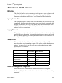
Overview .............................................................................................................................................
Model 4800 Principle of Operation .....................................................................................................
Intended Use ........................................................................................................................................
Anesthetic Gas Module .......................................................................................................................
Cautions and Warnings ........................................................................................................................
Cleaning ...............................................................................................................................................
Calibration ...........................................................................................................................................
Anesthetic Gas Module .......................................................................................................................
Patient Connection ...............................................................................................................................
Alarm Messages .................................................................................................................................
Accessories .........................................................................................................................................
Module Specifications ........................................................................................................................
vi
24-1
24-1
24-2
24-2
24-2
24-3
24-3
24-5
24-5
24-6
24-6
24-7
Mennen Medical®
Menntor X7® Operating Manual
Chapter 25:
Anesthetic Gas Monitoring
Overview ................................................................................................................................................. 25-1
Monitoring Procedures ......................................................................................................................... 25-1
EtCO2 Monitoring ............................................................................................................................... 25-2
O2, N2O, and Anesthetic Agent Monitoring Procedures .................................................................... 25-9
Activating Monitoring ........................................................................................................................ 25-16
MAC (Minimum Alveolar Concentration ) ....................................................................................... 25-17
Chapter 26:
Ventilator
Overview .............................................................................................................................................. 26-1
Ventilator Parameters ........................................................................................................................... 26-2
Monitoring Procedures ......................................................................................................................... 26-2
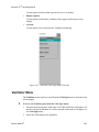
Ventilator Menu ................................................................................................................................... 26-3
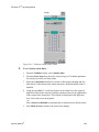
Setting Alarms ...................................................................................................................................... 26-4
Setting Ventilator Display Options ...................................................................................................... 26-7
Activating and Deactivating Ventilator Monitoring .......................................................................... 26-10
Alarm Messages ................................................................................................................................. 26-11
Chapter 27:
BIS - Bispectral Index
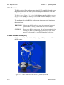
Introduction .......................................................................................................................................... 27-1
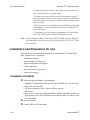
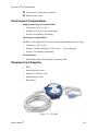
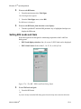
Installation and Preparation for Use ..................................................................................................... 27-4
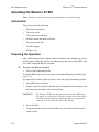
Operating the Menntor X7 BIS ........................................................................................................... 27-8
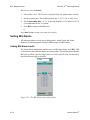
Monitoring Procedures ....................................................................................................................... 27-10
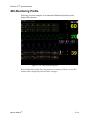
BIS Monitoring Profile ...................................................................................................................... 27-21
BIS Cleaning and Preventive Maintenance ...................................................................................... 27-24
Service ............................................................................................................................................... 27-25
BIS Trouble Shooting ........................................................................................................................ 27-26
Chapter 28:
CO/CCO/SvO2
Overview .............................................................................................................................................. 28-1
UIM Input as Vigilance/Vigileo/PiCCO .............................................................................................. 28-3
CO/CCO Monitoring Procedures ......................................................................................................... 28-4
SvO2 Monitoring Procedures ............................................................................................................... 28-7
Trend .................................................................................................................................................. 28-10
Chart ................................................................................................................................................... 28-10
Chapter 29:
Radical 7 – Masimo CO-Oximeter
Overview ..............................................................................................................................................
Technical Alarms .................................................................................................................................
Calibration ............................................................................................................................................
Monitoring Procedures .........................................................................................................................
Setting SpO2 Alarms limits .................................................................................................................
Setting SpHb Alarm Limits ..................................................................................................................
Mennen Medical®
29-1
29-2
29-2
29-2
29-3
29-3
vii
Menntor X7® Operating Manual
Setting SpCO Alarm Limits ................................................................................................................
Setting SpMet Alarm Limits ...............................................................................................................
Display Options ...................................................................................................................................
Sensors .................................................................................................................................................
29-3
29-3
29-3
29-3
Chapter 30:CerebraLogik- aEEG and EEG
Introduction ......................................................................................................................................... 30-1
CerebraLogik Label ............................................................................................................................. 30-4
CerebraLogik - Waveforms and Display Modes ................................................................................. 30-4
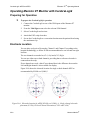
Operating Menntor X7 Monitor with CerebraLogik ........................................................................... 30-6
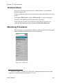
Technical Alarm .................................................................................................................................. 30-7
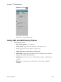
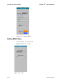
Monitoring Procedures ........................................................................................................................ 30-7
CerebraLogik Display Modes ............................................................................................................ 30-11
aEEG History ..................................................................................................................................... 30-15
EEG Sections ..................................................................................................................................... 30-18
Data Storage and Export .................................................................................................................... 30-20
Recording .......................................................................................................................................... 30-24
Printing .............................................................................................................................................. 30-25
Routine Maintenance ......................................................................................................................... 30-25
Chapter 31:
Train Of Four [TOF]
Introduction ......................................................................................................................................... 31-1
Interfacing with TOF-Watch ............................................................................................................... 31-2
Section 5
Modules
Chapter 32:
Recording and Printing
Introduction .........................................................................................................................................
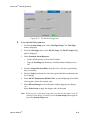
Network Printer ...................................................................................................................................
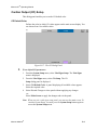
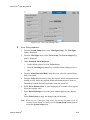
Enscribe – Network Strip Chart Recorder. ..........................................................................................
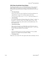
Built-in Strip Chart Recorder. .............................................................................................................
32-1
32-1
32-2
32-6
Chapter 33:
MX57- MPM as Transport Monitor
Introduction .........................................................................................................................................
General Description .............................................................................................................................
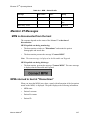
MPM Service Messages ......................................................................................................................
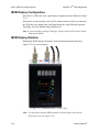
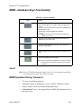
MPM – Hardware Keys Functionality ................................................................................................
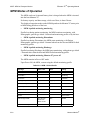
MPM Modes of Operation ...................................................................................................................
Menntor X7 Messages .........................................................................................................................
33-1
33-2
33-3
33-5
33-6
33-7
Chapter 34:
Spirometry
Overview .............................................................................................................................................
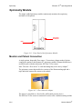
Spirometry Module ..............................................................................................................................
Monitoring Procedures ........................................................................................................................
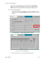
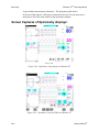
Screen Captures of Spirometry displays: ............................................................................................
34-1
34-4
34-5
34-6
viii
Mennen Medical®
Menntor X7® Operating Manual
SECTION 6
Appendixes
Appendix A:
Accessories
Appendix B:
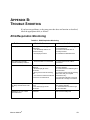
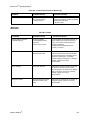
Trouble Shooting
ECG/Respiration Monitoring ................................................................................................................
Response to Single Lead Fault ..............................................................................................................
Invasive Blood Pressure Monitoring .....................................................................................................
EtCO2 ....................................................................................................................................................
B-1
B-2
B-2
B-3
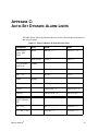
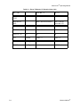
Appendix C:
Auto-Set Dynamic Alarm Limits
Appendix D:
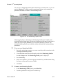
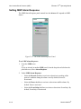
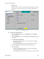
Setting Up the System
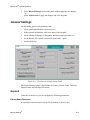
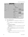
Introduction ........................................................................................................................................... D-2
Date & Time Setup ............................................................................................................................... D-8
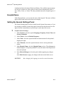
General Settings .................................................................................................................................. D-11
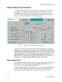
Alarm Volume and Controls ............................................................................................................... D-14
Sound Event ........................................................................................................................................ D-17
Default Alarm Limits .......................................................................................................................... D-18
Event Setup ......................................................................................................................................... D-20
Vital Sign (VS) Setup ......................................................................................................................... D-22
Parameter Hierarchy ........................................................................................................................... D-52
Monitor Profiles Setup ........................................................................................................................ D-54
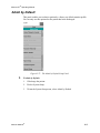
Admit by Default ................................................................................................................................ D-57
Report Setup ........................................................................................................................................ D-58
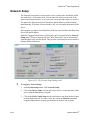
Network Setup ..................................................................................................................................... D-64
IP Address Setup ................................................................................................................................. D-65
Recorder Setup .................................................................................................................................... D-65
Trends Setup ....................................................................................................................................... D-67
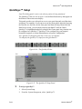
QuicKeys™ Setup ............................................................................................................................... D-68
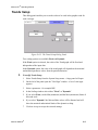
Tabular Charts ..................................................................................................................................... D-69
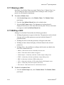
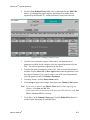
Updating the Software Version ........................................................................................................... D-72
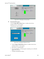
Enmove™ Interface Setup .................................................................................................................. D-75
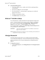
Change Password ................................................................................................................................ D-75
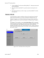
Check Disk .......................................................................................................................................... D-76
Permission Editor ................................................................................................................................ D-77
Remove Saved Patients ....................................................................................................................... D-78
Touch Screen Calibration .................................................................................................................... D-78
Demo Activation ................................................................................................................................. D-78
Copy Configuration Utility ................................................................................................................. D-79
Appendix E:
Setting Up the Interface Between Vigileo and Menntor X7
Mennen Medical®
ix
Menntor X7® Operating Manual
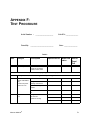
Appendix F:
Test Procedure
Appendix G:
Declaration of conformity to IEC 60601-2-27
x
Mennen Medical®
SECTION 1
INTRODUCTION
This section contains the following chapters:
1. What You Should Know
2. Warnings and Safety Precaution
3. System Description
4. Installation
5. Maintenance and Cleaning
6. Controls and Functions
1
Menntor X7® Operating Manual
2
Mennen Medical®
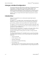
CHAPTER 1:
WHAT YOU SHOULD KNOW
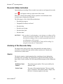
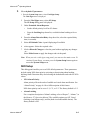
Training
Mennen Medical or it's authorized distributer will provide training for the system
user as per the intended use of the device or system.
The training may be personal or by training the trainers.
The scope of the training is part of the agreement between Mennen Medical or it's
authorized distributer and the end user.
It is the responsible of the hospital management that only users that were trained to
use the equipment efficiently and safely, should operate the equipment
Service
Only Service Engineers trained and approve by Mennen Medical are allowed to
perform service to Mennen-Net equipment.
Monitor configuration is password protected and is allowed to users that have
received permission by the hospital System Manager or administrator.
"Menntor X7 Service manual" will be provided to Service Engineers trained and
approve by Mennen Medical.
Prescription Notice
CAUTION!
Federal law restricts this device to sale by or on the order of
qualified medical personnel only.
User Capability
Patient monitors are used by nurses under the supervision of physicians.
System Setup, is password protected and should be modified only by the System
Manager authorized by the department director (a Physician).
Mennen Medical®
1-1
Menntor X7® Operating Manual
What You Should Know
General Description
Menntor X7, is a modular patient monitor with a Multi Parameter Module MX57
that serves as a front end amplifier and signal conditioner for the commonly used
vital signs, and two additional plug-in modules.
The MX57-MPM will be offered for either Non Invasive monitoring or Invasive
monitoring.
In the Non Invasive option it will measure: ECG/Resp/2Temp/NIBP/SpO2
In the Invasive option it will add measurement of 2 or 4 Invasive blood pressures
and Cardiac Output.
The MX57 -MPM will have an optional LCD display [751-OPT-057], that will
allow it use the MPM as a transport monitor (see chapter 33 ).
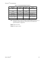
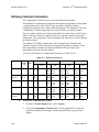
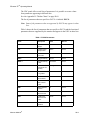
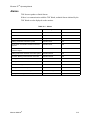
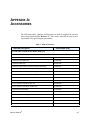
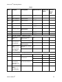
Menntor X7 Part Numbers
The following tables provide part numbers for Menntor X7.
Table 1-1: Menntor X7 host Part Numbers
Part Number
Description
791000000
Menntor X7 Base Unit Assembly
791OPTXXX
Menntor X7main frame
791OPT012
Menntor X7 Touch Screen Option
791OPT014
Menntor X7 Non Touch Screen Option
791OPT010
Menntor X7 Battery Option One Battery
791OPT020
Menntor X7 Battery Option Second Battery
791OPT119
Menntor X7 Wireless Option EU
791OPT219
Menntor X7 Wireless Option UA
791OPT400
Menntor X7 Recorder Option
791OPT008
Menntor X7 Flash Memory 16GB Option
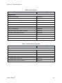
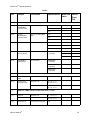
Table 1-2: MX57 Multi Parameter Module Part Numbers
Part Number
Description
Non Invasive monitoring
751000010
1-2
MX57 (3/5ECG/Resp/2Temp/NIBP/SpO2) Covidien
Mennen Medical®
Menntor X7® Operating Manual
Table 1-2: MX57 Multi Parameter Module Part Numbers
Part Number
Description
751000012
MX57 (12ECG/Resp/2Temp/NIBP/SpO2) Covidien
751000020
MX57 (3/5ECG/Resp/2Temp/NIBP/SpO2) Massimo
751000022
MX57 (12ECG/Resp/2Temp/NIBP/SpO2) Massimo
751010012
MX57 (12ECG/Resp/2Temp/NIBP/SpO2) Covidien LCD
751010022
MX57 (12ECG/Resp/2Temp/NIBP/SpO2)Massimo LCD
Invasive Monitoring
751010212
MX57 (12ECG/Resp/2Temp/NIBP/SpO2/2IBP/CO) Covidien LCD
751010412
MX57 (12ECG/Resp/2Temp/NIBP/SpO2/4IBP/CO) Covidien LCD
751010222
MX57 (12ECG/Resp/2Temp/NIBP/SpO2/2IBP/CO) Massimo LCD
751010422
MX57 (12ECG/Resp/2Temp/NIBP/SpO2/4IBP/CO) Massimo LCD
751OPT119
MX57 Wireless Option EU
751OPT219
MX57 Wireless Option UA
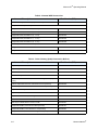
Table 1-3: Plug in modules
Part Number
Description
ETCO2 module
751142000
Spirometry module
751137000
Manual Structure
The manual is divided into four sections.
•
Section 1 introduces the Menntor X7 bedside monitor and provides a general
overview of the system, including standard operating techniques.
•
Section 2 includes a general discussion of alarms. It also provides information
about setting up the patient display, admission and discharge procedures and
reviewing patient data.
•
Section 3 describes vital sign monitoring procedures performed by the
Menntor X7 bedside monitor.
•
Section 4 includes appendixes referring to available accessories and
troubleshooting.
Mennen Medical®
1-3
What You Should Know
Menntor X7® Operating Manual
Changes in Default Configuration
This manual describes the standard default configuration of all parameter functions
in the Menntor X7 bedside monitor as provided by Mennen Medical. This
configuration can be changed according to your hospital’s needs by your
Biomedical Engineering department, System Administrator or a Mennen Medical
service engineer. If any deviation from the description provided in this manual is
apparent, consult your hospital’s Biomedical Engineering department or System
Administrator.
Intended Use
Menntor X7 is intended for use as a multi-parameter physiological patient
monitoring system.
The Menntor X7, is a modular monitor with a Multi Parameter Module (MX57,
MPM) that can monitor ECG/heart rate, invasive blood pressures, temperature,
pulse oximetry, respiration, non-invasive blood pressure, and Cardiac Output
The Menntor X7 can also monitor EtCO2, Spirometry and EEG, and display aEEG.
The MPM (MX57) is equipped with a battery and can continue monitoring it's vital
sign when out of the host Menntor X7
This effectively allows the Menntor X7 to monitor a wide-range of adult, pediatric
and neonatal patient conditions, in many different areas of the hospital.
Functions include display of multi-parameter waveforms, vital signs, alarm &
status messages.
The Mennen Medical Menntor X7 is intended for sale as a system for monitoring
and recording patient information on any in-hospital application requiring patient
monitoring.
1-4
•
Critical Care Patients
•
Cardiac Step-down Units
•
Emergency Departments
•
Intra-operative (Anesthesia) Monitoring
•
Post Anesthesia Care
•
VitaLogik 6000 6500 has full monitoring capacity and includes: ECG, NIBP,
SpO2, Temperature, 2 (4 - optional) BP and CO/2 Temp with optional EtCO2
Mennen Medical®
Menntor X7® Operating Manual
Compliance
The Menntor X7 bedside monitor is designed to comply with the international
safety requirements for medical electrical equipment IEC 60601-1, IEC 60601-1-8,
IEC 60601-2-27, IEC 60601-2-49, and AAMI voluntary performance standards for
cardiac monitors.
The Menntor X7 bedside monitor is also designed to comply with the international
EMC requirements for medical electrical equipment IEC 60601-1-2.
European Directive 93/42/EEC as amended by 2007/47/EC, classifies the Menntor
X7 bedside monitor as a Class IIb device. The NIBP and SpO2 are classified as
Type BF equipment. The ECG and Dual BP and CO/2 Tmp are classified as Type
CF equipment for direct cardiac application. (See page 2-5 for the relevant
symbols used on the inputs.)
The inputs are floating inputs and are protected against the effects of defibrillation
and electrosurgery. If the correct electrodes are used and applied in accordance
with the manufacturer’s instructions, the screen display will recover within 5
seconds of defibrillation. The Menntor X7 is designed as a Type CF equipment to
have special protection against electric shocks (particularly regarding leakage
current) and is defibrillator proof.
Mennen Medical®
1-5
Menntor X7® Operating Manual
What You Should Know
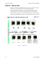
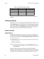
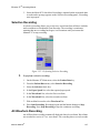
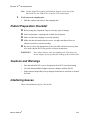
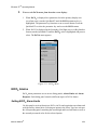
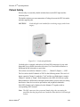
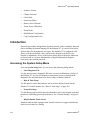
Network – Mennen-Net
Menntor X7 and all other Mennen Medical monitors can be connected to a Local
Area Network – LAN by wired or wireless connection (optional).
The Network enables the Ensemble – Central Nurse Station and the Enguard –
Remote Monitor to view patient data at the central station or doctor's room.
It also enables each monitor to view remote monitors that are on the Mennen-Net.
Interface to Hospital Information System – HIS is also available via a server router.
Figure 1-1: Mennen-Net
1-6
Mennen Medical®
CHAPTER 2:
WARNINGS AND PRECAUTIONS
The terms Warning, Caution, and Note have specific meanings in this chapter.
WARNING!!! advises against certain actions or situations that could result in
personal injury or death.
CAUTION! advises against actions or situations that could damage equipment,
produce inaccurate data, or invalidate a procedure, although personal injury is
unlikely.
NOTE provides useful information regarding a function or procedure.
The Menntor X7 bedside monitor is designed to comply with international safety
requirements for medical electric equipment, and AAMI voluntary performance
standards for cardiac monitors.
WARNING!!!: Do not use the unit in an atmosphere with flammable anesthetic
mixtures.
The system is designed to have special protection against electric shocks and is
defibrillator-proof.
WARNING!!!: Do not touch the patient, bed or instrument during defibrillation.
CAUTION!
Connect the monitor to the main power whenever available. Note
that when the monitor works on battery a "Battery" label appears
on the display.
WARNING!!!
The use of the ME EQUIPMENT is restricted to one patient at a
time.
Power Failure
The monitor is equipped with battery backup to ensure continuous monitoring in
case of a power failure. However , if a prolonged power failure is expected, it is
strongly recommended to use Un Interrupted Power Supply - UPS to ensure
continuous monitoring in case of power failure.
Mennen Medical®
2-1
Warnings and Precautions
Menntor X7® Operating Manual
Minimizing Electrosurgical Interference
How Electrosurgery Interference Affects Patient Monitoring
An electrosurgery (ES) device uses voltages which may interfere with the
monitored ECG. Radio Frequency (RF) voltages ranging from hundreds to
thousands of volts generated by these ES devices are present at the active electrode
and are transferred directly to the patient’s body during electrosurgery.
This produces ES interference in one, or both, of two possible modes. The most
important is “conduction”, in which case the RF signal is carried on and through
the patient’s body. The other, “radiation”, occurs when RF noise is transmitted
through the air and induced in the monitoring devices and their cables.
Suppose that an ES device is set so that the voltage at the active electrode in 100
volts (approximately the minimum setting). Assuming a reduction (attenuation) of
the signal by 100,000 times through the body’s natural impedance and by electrical
filtering, the ES signal at the ECG lead connection would still be 1 millivolt - just
equal to the magnitude to the ECG signal. Complicating the situation is the fact that
some electrosurgery devices are designed to superimpose other signals on the RF to
generate different cutting or coagulating effects.
These superimposed signals are often at the same frequencies as ECG components,
making it difficult to separate the unwanted interference from the ECG signal with
electronic filters. Good monitoring techniques, however, may be used to enhance
the quality of the signal, reducing the burden on the filtering.
Conduction
The electrosurgery RF signal flows through the patient from the active electrode to
the return plate. If the return plate is directly opposite the active electrode, most,
but not all, of the energy goes directly to the return plate. The stray ES voltage
spreads out over and through the body, becoming smaller as it moves away from
the active electrode. Sites farther from the active electrode have smaller RF signals
than those which are close.
Another aspect of interference is caused by the way in which this RF
electrosurgical signal spreads away from the active electrode. Because the spread
of the signal is basically symmetrical, two sites equidistant from the active
electrode will receive basically the same signal, or will be at basically the same RF
voltage.
Menntor X7 amplifiers measure the difference in voltage between their positive
and negative inputs. If the ECG electrodes are placed at equal distances from the
active electrode, they will have equal RF voltages. With no voltage difference
between the positive and negative inputs, the ECG amplifier will have no RF
voltage difference to measure and, therefore, no interference. In actual practice, it
2-2
Mennen Medical®
Menntor X7® Operating Manual
is probably impossible to place the electrodes exactly equidistant from the active
ES electrode. The effort in attempting to do so, however, is well spent, as it tends to
minimize the magnitude of “difference mode” interference.
In summary, conduction interference can be minimized by:
1.
Using the lowest possible ES power setting.
2.
3.
4.
5.
Placing the return plate directly under the surgical site.
Placing the ECG electrodes as far from the ES site as possible.
Placing the ECG electrodes equally distant from the ES site.
Placing the ECG electrodes on the frontal or all on the posterior surface.
Radiation
Radio frequency (RF) voltage always generates an electromagnetic. The intensity
of the radiated field, at any point in space, is directly proportional to the source’s
voltage and inversely proportional to the distance from the source. In the case of
electrosurgery, the active electrode, return plate, and their cables act as transmitting
antennas.
Electromagnetic fields radiate perpendicular to their associated cables. Therefore,
susceptibility of the ECG cable to this RF is maximum when the ECG cable is
parallel to the ES cable. Separating or placing cables perpendicular to one another
will minimize radiation coupling effects.
In summary, radiation interference can be minimized by:
1.
2.
Using the lowest possible ES power setting.
Keeping ECG cables as far from ES cables as possible.
3.
Keeping ECG cables at right angles to ES cables.
Electrical Shock Hazard
The monitor is designed according to IEC 60601-1 safety standard.
The front-end of all applied parts has double isolation which ensures that the
leakage current will not exceed the safety limits.
Connection of Other Medical Devices
Connection of other medical devices to the Menntor X7, unless specifically
recommended by Mennen Medical, Ltd., may compromise the performance and/or
patient safety of the unit. When in doubt, contact the company for specific
compatibility data.
Mennen Medical®
2-3
Menntor X7® Operating Manual
Warnings and Precautions
WARNING!!!
Connection of other medical devices without Mennen Medical
approval might jeopardize patient safety.
Explosion Hazard
This device is not intended for use in the presence of flammable anesthetic agents.
Environmental Status
When the Menntor X7 is working on battery, the environmental temperature should
not exceed 400C .
The battery should be stored, separated from the monitor, at a temperature that does
not exceed 25 0C.
Monitor Storage
CAUTION!
If the monitor is stored for a long period, remove the battery and
store it separately.
Use of Manual
The instructions for use presented in this manual should in no way supersede
established medical protocol concerning patient care.
Responsibility
Mennen Medical, Ltd. considers itself responsible for the effects on safety,
reliability, and performance of the equipment only if:
•
•
•
Repairs are carried out by authorized Mennen Medical personnel only.
Electrical installation of the relevant room complies with the appropriate
requirements.
The equipment is used in accordance with instructions for use.
WARNING!!!
2-4
Do not modify this equipment without the authorization of the
manufacturer.
Mennen Medical®
Menntor X7® Operating Manual
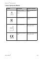
Labeling
Symbols
The following is a short description of the meaning of the various symbols which
appear on the Menntor X7 and their location on the equipment.
Symbol
Mennen Medical®
Description
Location of Symbol
Alternating Current
At the rear of the Processing unit.
Equipotential
At the rear of the Processing unit.
Attention, consult accompanying documents (Service to be performed by qualified technician, consult service manual
before removing cover)
On Processing unit.
Off (power disconnection from main
power supply)
On right of Processing unit.
On (power connection to the main power
supply)
On the right of the Processing unit.
Type BF applied part
defibrillator-proof
On NIBP and SpO2.
Type CF applied part - direct cardiac
application
defibrillator-proof
On ECG, and Dual BP and CO/2
TMP.
Fuse
At the rear of Processing unit.
Type BF applied part
On CerebraLogik input
Refer to instruction manual/ booklet
On device label
Restricts the sale and use of this instrument to qualified medical personnel
only.
On device label
Not for use in explosive gas environment
On device label
2-5
Menntor X7® Operating Manual
Warnings and Precautions
Symbol
Description
Location of Symbol
Electrical and electronic equipment Dispose according to local regulation
On device label
Date of manufacture
On device label
CE Mark
On device label
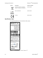
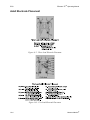
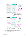
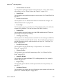
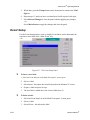
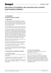
Identification Label
The Identification label is located at the back of the monitor.
.
Figure 2-1: The Indentification Label Menntor X7
2-6
Mennen Medical®
Menntor X7® Operating Manual
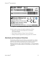
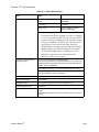
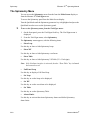
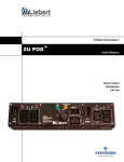
.
Figure 2-2: The Indentification Labels MX57 - MPM
The labels includes warnings and compliance information as follows:
•
Identification information: Part Number (P/N), Serial Number
(S/N), and model name
•
Electrical power information: Voltage, Current, and Frequency
•
Warnings: Disconnect supply before servicing, replace fuse as marked
Electrode and Transducer Protection
The Electrodes and Blood Pressure Transducers recommended for use with the
equipment and the equipment itself are provided with protective means against
burns to the patient when used with high frequency surgical equipment.
Immunity requirements of IEC Collateral Standard 60601-1-2 for Electromagnetic
Compatibility are met with the transducers recommended for use with the unit (see
Appendix A).
Mennen Medical®
2-7
Menntor X7® Operating Manual
Warnings and Precautions
General Use of Accessories
•
Use only Mennen Medical approved accessories with the Menntor X7. This
includes, but is not limited to, those accessories approved for use with the Vital
Signs: ECG, BP, CO/Temp, NIBP, SpO2, and EtCO2.
•
Do not use a damaged accessory. Always refer to the instructions for use
included with each accessory.
•
A disposable (single patient) accessory should not be sterilized or cleaned for
reuse.
•
Use care when installing accessories such as adapters and cables. Do not use
force. Do not cause tension in cables when connecting them to the vital signs
sockets.
CAUTION!
Accessories are connected to the monitor using interface cables.
Take special care to prevent cable entanglement.
Take care not to pass the cables around the patient's head and
neck in order to prevent possible strangulation.
Disposal of Monitors and Accessories
Dispose of the equipment and its accessories, according to the rules and regulations
of your country.
2-8
Mennen Medical®
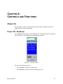
CHAPTER 3:
SYSTEM DESCRIPTION
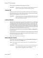
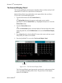
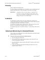
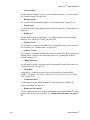
Overview
The Menntor X7 bedside monitor is a standalone bedside unit consisting of a main
processing unit and a built-in color monitor.
The Menntor X7 monitors the patient's vital signs.
The vital signs data derived by the Menntor X7 is presented on the monitor as
waveform and numeric displays.
The Menntor X7’ user interface is especially designed for user-friendly operation.
The fixed buttons and unique QuicKnob™ control on the front panel of the main
processing unit enables quick and direct access to system parameters and
functions.
An optional Touch Screen is available for control of the Menntor X7 setting and
menus without the hardware keys and QuicKnob™.
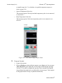
Figure 3-1: The Menntor X7 Bedside Monitor
Mennen Medical®
3-1
Menntor X7® Operating Manual
System Description
System Features and Capabilities
The Menntor X7 displays a wide range of vital sign clinical parameters. It
includes:
•
ECG/Respiration multi-lead for monitoring ECG and respiration.
•
Dual (four optional) BP inputs for monitoring two invasive blood pressures.
•
CO/2TMP connector to measure either thermodilution Cardiac Output or two
temperatures.
•
Temp connector.
•
NIBP input for monitoring non-invasive blood pressure using the oscillometric
method.
•
Pulse Oximetry.
•
Microstream End Tidal CO2 (EtCO2) for monitoring CO2 during exhalation
(EtCO2) and inhalation (inCO2) and Respiration Rate.
•
CerebraLogik dual channel EEG and aEEG
•
Serial Input for communication and interface with an external, auxiliary
device.
The Menntor X7’s main monitoring features include:
•
Continuously updated vital sign parameter data displayed as numeric values
and continuous waveforms.
•
Clinical and technical alarm detection as well as alarm notification in audio
and visual formats.
•
Easy access to collected data in the form of tabular charts and graphical trends
as well as various types of clinical reports.
•
Patient data output to a recorder or a printer, if connected.
You can interact with the Menntor X7:
•
Using interactive panels
These panels include menus and dialog panels that enable you to configure
system and monitoring parameters.
•
Responding to Events
Fixed keys on the front panel of the main processing unit enable you to
respond quickly to events such as alarms.
•
3-2
Reviewing Clinical Data
Mennen Medical®
Menntor X7® Operating Manual
Charts, Trends, Full Disclosure and Overview enable you to view and compare
data in different formats and over selected time periods.
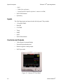
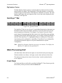
Monitor and Main Processing Unit
The Menntor X7 can display up to eight traces, depending on how the vital sign
display is configured. For monitor control procedures, refer to the User’s Manual.
All clinical data collected from the inputs is stored in the main processing unit.
This data includes waveforms, vital signs, trends, charts and beat-to-beat data.
The main processing unit can store at least 4 days of patient waveform and 80 days
of numeric data for review purposes. The front panel of the main processing unit
contains 7 fixed keys, and the QuicKnob™. These features enable you to interact
with the system. The back panel contains the power connector.
A remote keypad provides direct access, via the orange keys, to the menus of Vital
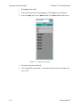
signs, Patient data, and Setup, via the green keys, to Event, Print, Record, and
Freeze and by the yellow key to Timer.
This allows the user to reach these functions without opening the Main menu.
For a detailed description of the functions and controls of the main processing unit,
see “Main Screen Display Features” on page 6-3.
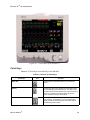
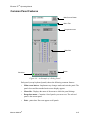
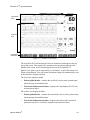
Display Features
The main screen display is divided into four areas:
•
Global Header Area
•
Patient Area
•
Patient Display Area
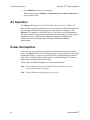
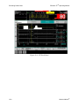
•
QuicKeys™
For a description of all monitor display features and functions, see “Main Screen
Display Features” on page 6-3.
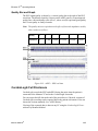
Input Modules
The Vital Signs inputs modules are housed on the left side panel.
They include
•
MX57 Multi Parameter Module providing inputs for:
• 12 Lead ECG/RSP
• Dual BP (4 optional)
• CO/2TMP
• Temp
• NIBP
Mennen Medical®
3-3
Menntor X7® Operating Manual
System Description
• SpO2
• 2 UIM (Universal inputs)
• CerebraLogik EEG amplifier (Optional - connected via UIM)
•
EtCO2 MicroStream
•
Spirometry
Inputs
The Vital Signs inputs are housed on the left side panel. They include:
•
12 Lead ECG/RSP
•
Dual BP
•
CO/2TMP
•
Temp
•
NIBP
•
SpO2
•
EtCO2 MicroStream
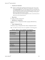
Controls and Outputs
•
Video output for external display
•
External keyboard and mouse
•
Remote keypad or Analog output
•
EtCO2 gas outlet
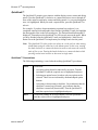
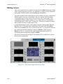
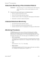
Figure 3-2: Menntor X7 Front Panel
3-4
Mennen Medical®
Menntor X7® Operating Manual
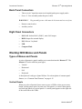
Figure 3-3: Menntor X7 Remote Keypad
Menntor X7 Analog Output
The back DB9 connector can be defined during PO with following options:
•
AUX
•
MCU Remote.
The table below provides the DB9 pin out for the AUX option.
Table 3-1: 9 PIN on the UUT rear panel AUX Connector (option)
Pin
Signal
Amplitude
1 (pin 5 ground)
ECG II
1 Volt p-p / 1 mV
2 (pin 6 ground)
ECG V1
1 Volt p-p / 1 mV
3 (pin 7 ground)
ECG Sync
Square pulse 5v,
100 mSec, 40
KΏ
4(pin 6 ground)
ART Pressure
1Volt / 100mHg
Monitors Network
The Menntor X7 can be used as part of a LAN network on which all Mennen
Medical monitors and devices are connected.
The network uses a Multiport managed layer 3 switch between all Mennen
Medical devices
The LAN network enables Bed to Bed communication as well as connections to:
•
Mennen Medical®
Ensemble – Central Nurse Station
3-5
Menntor X7® Operating Manual
System Description
•
Enguard – Remote monitor
•
Enscribe – Strip chart recorder
•
Laser network Printer.
Wireless Network (optional)
Monitors equipped with the wireless network option can interface with the
monitor's LAN without a hardwire connection.
Note: No change in functionality will occur as long as the wireless connection is
functioning.
The wireless technology uses a protected wireless network. To prevent loss of data
or alarms due to interference, numeric vital signs and alarms are sent to the
network every second.
If the monitor is equipped with wireless LAN network transceiver, the RF energy
detected by the monitor is displayed near the antenna icon.
WARNING!!!
If the RF energy is low, the monitor will not be viewed by the
central nurse station.
CAUTION!
Consult hospital Biomed, on the area covered by wireless LAN
accesses points.
Leaving this area will not effect the monitor function , but the
central nurse station will have no display nor control over the
monitor.
Interface with Hospital Network
Mennen Medical monitors can interface with the Hospital Information System –
HIS.
Interfacing with the HIS requires using a Mennen Medical Server to switch
between the Mennen Medical LAN and the hospital LAN.
The interface requires customization and an agreement between Mennen Medical
and the hospital IT department. To provide this interface, contact the Mennen
Medical Service department.
3-6
Mennen Medical®
Menntor X7® Operating Manual
System Specifications
See the following pages.
Mennen Medical®
3-7
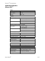
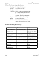
Menntor X7 Specification
Menntor X7 is a modular monitor consisting of a Host Monitor a
Multi Parameter Module, and two Single Parameters Modules.
Menntor X7 Host Monitor Specification
Hardware and Parameters
Network
Menntor X7 is a modular monitor with a built-in
display and battery back-up.
MX57 - Multi Parameters Module
Invasive
• 3/5/12 lead ECG
• Respiration
• NIBP
• SpO2 (Nellcor®)
• 2 Temperatures/ 4 Temeratures
• 2 x IBP (optional 4 IBP available)
• CO / 2 additional Temperatures
Non Invasive
• 3/5/12 lead ECG
• Respiration
• NIBP
• SpO2 (Nellcor®)
• 2 Temperatures
Universal Input Module - ”UIM”
• 2 x RS232 ports
• Interface to other vendor devices:
◊ Anestheic gases: Poet IQ, Andros 4800, Leon Plus, IRMA
◊ Ventilators: EVITA, Monet, Matisse, Saturn Evo, Stephanie, Babylog VN500
◊ Continuous CO: Vigilance, Vigileo, PiCCO2
◊ Other: BISx, CritiCool, Micropod, Radical-7, CerebraLogik
Display-Host Unit
• LCD (1024x768): 15”
• Waveform display horizontal area: 195 mm
• Numeric Display
◊ horizontal area: 95 mm
◊ vertical area: 23 mm
• Very Big Numbers
◊ One or Two Lead ECG WF
◊ HR height: 45 mm
◊ Four areas with Waveform height: 15 mm
◊ Numeric Vital Signs height: 35 mm
● Interface to a Remote Display
Waveform Display - Standard
7 sec, grid 5 boxes/sec (25 mm/sec nominal)
up to 8 traces and up to 14 traces (during 12 lead ECG)
Overlapping Pressure Waveforms mode
Sweep Speed: 6.25, 12.5, 25, 50, 100 mm/sec (nominal)
Cardio Respiratory Graph (CRG) - up to 4 parameters
Big Numbers
Waveform + Trend Format: 2/3 waveforms and 1/3 graphic Trend
Very Big Numbers mode
•
•
•
•
•
•
•
•
•
Host CPU Details
•
•
•
•
•
•
Via X 86 Core Fusion CPU
Sound Blaster 2W audio power / 8Ω
Mass storage: 8 GB / 16 GB
Operating System: QNX 4.25
Window manager: Photon
SW upgrades via network or memory card
•
•
•
•
LAN Physical: IEEE 802.3 Ethernet interface 10/100 BaseT
Protocol: TCP/IP
Serial Interface RS232 (optional)
Connectivity to: Ensemble (CNS), Enguard, Enscribe (recorder)
and network printer
• Wireless LAN (optional) includes:
◊ Utilizes an industry-standard 802.11b/g IEEE compliant radio card
◊ Dual-diversity dipole antenna
◊ Signal strength indicator
◊ WPA security and encryption
User Controls- Host Unit
•
•
•
•
•
6 Fixed Keys
Quicknob
Remote Control Keypad (optional)
Touch Screen—ELO IT (optional)
Barcode Reader (optional)
Patient Data storage- Host Unit
•
•
•
•
•
•
Demographic Data
Charts - Numerical
Trend - Graphic
Full Disclosure - All leads ECG waveform
Overview - All Waveforms with top ECG
Event Strips – 20 Seconds of all ECG and Vital signs waveforms
(10 sec pre & post event)
Calculations - Host Unit
●
●
●
●
●
●
●
Medications
Hemodynamics
Respiratory Mechanics
Oxigenation
Renal Clearance
Fick Cardiac Output
Heart Rate Variability (HRV):
◊ Time Domain
◊ Histogram
Default Alarms - Host Unit
Menntor X7 with MX57 MPM Module
HxWxD: 361x392x215 mm (14.2x15.4x8.4 inches)
Weight: 8.5Kg. (18.7 lb) (for basic configuration with battery)
• User defined
• Fixed or calculated values
• Alarm levels:
◊ Clinical levels: C1, C2, C3, C4
◊ Technical levels: T1, T2.
• Visual and Audible alarm
• Output Alarms by Analog Switches
Power requirement
Recorder (Optional) - Host Unit
Dimensions\Weight
• Integrated Recorder up to 3 channels
• 100-120 VAC, 2A, 50/60 Hz
• 230-240 VAC, 1A, 50 Hz
Analog Output - Host Unit
Battery
Menntor X7
Lithium Ion
Single Battery
Dual Battery
14.8V / 5.2A
14.8V / 10.4A
Operation Time (Hours)
3
6
Charge Time (Hours)
3
6
•
•
•
•
•
ECG II – 1Volt/mV (pin1, 5 Gnd)
ECG V1 – 1Volt/mV (pin2, 6 Gnd)
QRS – 5 Volt
ART – 1Volt/100 mmHg (pin4, 8 Gnd)
Output to input delay < 20 mSec
Languages
• English, Dutch, Espanol, French, Greek, Italian, Polish, Portuguese, Russian,
Environmental Operating Conditions
0
0
• Temperature: +5 C to +40 C (41°F to 104°F)
• Humidity: 10 to 93 percent, non-condensing
• Barometric Pressure: 430-795 mmHg (-1250 to 15,000 ft. ; -380 to 5200 meter)
Environmental Storage Conditions
• Temperature: -15CO to +68CO (5°F to 154°F)
• Humidity: 10 to 93 percent, non-condensing
DGM-781-001 Rev C 11/2014. Page 1/5
Spanish, Turkish.
Regulatory Approvals
•
•
•
•
EN 60601-1
EN 60601-1-1
EN 60601-1-2
Degree of protection against electrical shock
◊ ECG / RSP, IBP, CO and TEMP = Type CF
◊ NIBP, SpO2 and EtCO2 = Type BF
• CE Mark 0473
• FDA Clearance - K073140, K093766—Pending
• WIFI FCC ID XM5-SM2144N1/2
Industrial Canada 8516A-SM2144N1/2
Menntor X7
Technical Specification
MX57 - Multi Parameter Module
● The MPM, when disconnected from the host will serve as a stand alone transport monitor
● Monitor Profile and alarm setting are fixed, as received from the host
● Upon return to the host, the data collected during the transport will merge with
the data collected by the host
CPU Detail
•
•
•
•
Arm Cortex A8
AC97 Sound Card - 2W audio power 8 ohm
Mass storage: 2 GB
Operating System: Linux and TI CCD
Dimension / Weight
HxWxD: 170 x 80 x 225 mm (6.7 x 3.0 x 8.8 inches)
Weight: 1.4 Kg. (3.08 lb)
Display (optional)
• LCD (640 x 480): 5.7” optional
• ECG. One Waveform display horizontal area: 82 mm
◊ HR height 20 mm
Power - Battery operated
● Lithium Ion: 16.8 VDC / 2.6 A
● Operation Time: 5 (Hours)
● Charge Time: 4 (Hours) from host
Environmental Operating Conditions
• Temperature: +5C to +40C (41°F to 104°F)
• Humidity: 10 to 93 percent, non-condensing
User Controls
5 Fixed keys : Silence, Event Mark, IBP Zero, NIBP, On/Off
Data Storage
•
•
•
•
•
•
Storage time
Demographic Data
Numerical Vital Sign
Full Disclosure - All leads ECG waveform
Overview - All Waveforms with top ECG
Event Strips (for each event) – 20 Seconds of all ECG and Vital signs
waveforms 10sec pre & post event)
Alarms
• Alarm levels:
◊ Clinical levels: C1, C2, C3, C4
◊ Technical levels: T1, T2.
● Visual and Audible alarm
● Battery Status Alarm
Numeric Display
● 4 areas Big Numbers boxes
◊ horizontal area: 58 mm
◊ vertical area: 30 mm
● Vital Signs
◊ Waveform height: 11 mm
◊ Numeric Vital Signs height: 15 mm
◊ Sweep Speed: 6.25, 12.5, 25, 50, 100 mm/sec (nominal)
Single parameter modules
● EtCO2
● Spirometry
Dimension / Weight
HxWxD: 95 x 40 x 120 mm (3.7 x 1.6 x 4.7 inches)
Weight: 0.3 Kg. (0.6 lb)
MX57 - MPM Mounting (Optional)
DGM-781-001 Rev C 11/2014. Page 2/5
Menntor X7
Clinical Specification
• Leads: ECG cables for 3/5/12-lead surface ECG with defibrillation protection
•
•
•
•
•
•
•
•
•
•
•
•
•
•
•
•
•
•
•
•
•
•
•
•
•
•
•
•
•
•
•
in the cable.
Input Dynamic Range: ±5 mV peak to peak
Input DC Offset: ±530 mV
Baseline Correction: Automatic recovery of waveform within 100 msec
Notch Filtering: 50Hz or 60Hz
Frequency Response:
◊ Diagnostic 0.05 to 150Hz
◊ Monitoring 0.5 to 40Hz
◊ ST 0.05 to 40Hz
◊ Exercise 1 to 25Hz
Sensitivity: 0.25, 0.5, 1.0, 2.0, 4.0, 8.0 mV/cm (nominal)
Common Mode Rejection: 120 dB minimum
Noise: 30 µV
Input Impedance: 2.5 megaΩ
Defibrillator Pulse Protection: Yes
Baseline Recovery: < 8 sec
Lead Fault Sense: Based on impedance with driven lead: Sense current < 90 nA, DC
Digital Sample Rate: 640Hz
Sample Resolution: 24 bit
Pacemaker Detection and Rejection of Pacer Artifact.
◊ Amplitude: +/- 2 mV to +/- 700 mV
◊ Width: 0.1 ms to 2.0 ms
Pacer Detection Flag inserted into ECG waveform.
3 Detection Modes:
1. Fixed Threshold 2mV
2. Adaptive 1 Threshold ½mV High Sensitivity
3. Adaptive 2 Threshold > 2mV High Immunity
Auto Cable Detection
Audio Indicator: QRS Beep—Adjustable volume
QRS Detection Range:
◊ Height: 0.25 or 0.15 mV to 5.0 millivolt
◊ Width: 70 to 120 milliseconds
Heart Rate Counting:
◊ Range: 0 to 350 BPM
◊ 0-300 Accuracy: ±2 BPM, 300-350 Accuracy ±4 BPM
Heart Rate averaging:
3/4 of last average + 1/4 new beat (about 8 beats between 60 to 120, or 120 to 60)
Note: Values below 20- forced to zero
Heart Rate Alarm Settings
High and low rate: 20 - 350 BPM non-overlapping
Leads analyzed for Heart Rate and Arrhythmia Configuration:
◊ Top two displayed
ECG Leads:
◊ I, II, III (3 Lead cable)
◊ I, II, III, aVR, aVL, aVF, V (5 Lead cable)
◊ I, II, III, aVR, aVL, aVF, V1-V6 (12 Lead cable)
ST on all leads:
◊ Automatic or Manual
◊ ST range + 8 mm to – 8 mm
◊ ST Alarm
Arrhythmia: Detection and alarm on 19 Arrhythmias
PR and QT measurement and display
Data Storage:Beat notification, RR Interval, Heart Rate, ST values, Arrhythmia,
Alarms, Alarm event markers
Respiration
•
•
•
•
•
•
•
•
•
•
•
•
•
Leads: RA-LA or Leads: RA-LL
Excitation: 65 kHz Sinus wave, < 1 mA
Input Impedance: >40 KΏ
Frequency Response: 0.13 to 2.5Hz
Impedance Range: 100 to 3000 Ω
Input Sensitivity Range: 0.2 to 5 Ω
Digital Sample Rate: 640 Hz
Sample Resolution: 24 bit
Sweep Speed: ECG speed, 6.25, 12.5 mm/Sec (nominal)
Gain: Automatic or 1/8 to x 8
Respiration Rate Counting Range: 0 to 150 breaths/min
Respiration rate: Accuracy +/- 1 per minute
Respiration Alarm Settings
◊ Low rate: 0 - 150 BPM
◊ High rate: 0 - 150 BPM
◊ Apnea: User configurable (10, 15, 20, 30, 45, 60, 90 Sec.)
◊ Cardiac coincidence alarm
◊ Modes: Normal / Cardiac
• Data Storage: Respiration rate, Respiration rate Alarms, Apnea alarms
Alarm event markers
Invasive Blood Pressure
•
•
•
•
•
•
•
•
•
•
•
•
•
•
Site Labels: BPx, ART, PAP, CVP, RAP, LAP, ICP
Input Sensitivity: 5 µVolt/Volt/mmHg
IBP waveform synchronized to ECG
Dynamic Range
◊ Pressure range: -50 to +350 mmHg
◊ Zero range: ±150 mmHg
◊ Total dynamic range: -200 to +450 mmHg
◊ Heart rate: 20—350 BPM
Transducer Excitation Voltage: +5 VDC
Separate excitation driver for each channel
Zero Accuracy: ±0.2 mmHg
Zero Drift:
Less than ±0.2 mmHg in 24 hours, (at constant temperature)
Blood Pressure Accuracy:
±2 mmHg or ±2%, whichever is greater, exclusive of transducer
Blood Pressure Linearity: within 1% across entire range
Waveform Frequency Response: 0 - 40 Hz
Sampling Rate: 640 Hz
Sample Resolution: 24 bit
Fault Detection; Transducer in/out, Cable out
Data Storage:Systolic, Diastolic and Mean; Alarms
Pulse Oximetry (Sp02)
•
•
•
•
•
•
•
•
Nellcor® Oximax
Plethysmograph waveform
Saturation Range: 0% to 100% Sp02
Extreme Alarm Capability
Sp02 Accuracy: SpO2 % +/-3 digits standard deviation
Pulse Rate Range: 20 to 250 BPM +/-3 BPM
Saturation alarm limits: 0% to 100%
Data Storage:Heart rate and O2 saturation, Alarms
Thermo Dilution Cardiac Output
• Adapter and Compatibility Cables:
◊ CO Set interface cable
◊ Ice Bath YSI-400 cardiac output interface cable
◊ Dual temperature interface cable (YSI-400)
• Temperature Range
◊ Blood temperature: 270C to 450C (810F to 1130F)
◊ Injectate temperature: 00C to 250C (320F to 770F)
◊ Body temperature: 00C to 450C (320F to 1130F)
• Accuracy ±0.1OC over the entire range
• Digital Sample Rate: 160 Hz
• Sample Resolution: 24 bit
• Frequency Response: 0 to 15 Hz
• Cardiac Output Determination Range: 0 to 20 liters per minute
• Injectate Volumes: 1, 3, 5, and 10cc
• Displayed Data: Cardiac Output, Cardiac Index, Stroke Volume,
Stroke Volume Index, Blood Temperature, Injectate Temperature, Trial Number
• Data Storage:
In Cardiac Output mode: Cardiac Output, Hemodynamic Calculation results
Measuring time
In Two Temp mode: Temperatures and Delta-Temp, Temperature Alarms
Non-Invasive Blood Pressure
• Oscillometric Method
• Displayed Parameters: Systolic, Diastolic, Mean pressure values,
•
•
•
•
•
•
•
•
•
•
•
•
•
•
Time of last measurement, and next measurement
Cuff Size: Adult, Pediatric, Infant, Neonatal
Inflation Rate: Within 5 sec.
Initial inflation target: 150 mmHg, Adult/Pediatric
Initial inflation target: 100 mmHg, Neonatal
Over pressure limit : 290 mmHg, Adult/Pediatric
Over pressure limit : 145 mmHg, Neonatal
Cycle Times
Deflation time (typical): 30 sec.; BP time-out: 60 - 180 sec.
Measurement Ranges, Adult (in mmHg)
Systolic: 30 to 255; Diastolic: 15 to 220; Mean: 20 to 235
Measurement Ranges, Neonatal (in mmHg)
Systolic: 30 to 135; Diastolic: 15 to 110; Mean: 20-125
Pressure: Transducer Accuracy ±3 mmHg or ±2%, whichever is greater
Heart Rate:
◊ Adult/Pediatric: 30 to 240 BPM
◊ Neonatal: 40 to 240 BPM
Modes: Auto, Manual, STAT
Automatic intervals 1,2,3,4,5,10,15,20,30,60,120,180,240,360, 480 minutes
Data Storage: Measurement time markers, S/D/M, Alarm event markers
We follow every beat of your heart
DGM-781-001 Rev C 11/2014. Page 3/5
Mennen Medical Ltd. All rights reserved. Specification subject to be changed without notice.
ECG (3 / 5 / 12 Lead)
Menntor X7
Clinical Specification
Temperature
Anesthetic Gases Module
•
•
•
•
●
●
●
●
●
●
●
YSI 400 Series Probes
Body temperature: 00C to 450C (320F to 1130F) +/- 0.1 0C
Temperature Alarm Range: 250C to 450C (770F to 1130F)
Data storage: Temperature and Delta temperature, Temperature alarms
Delta Temperature
• Range + / - 45 0C
• Delta temp Accuracy: +/- 0.1 0C
End Tidal CO2 Microstream (EtCO2) Module
● Sidestream method
• Flow rate: 50 ml/min (accuracy: -7.5ml/min + 15ml/min )
• Displayed Data:
◊ Waveform labels and annotations
◊ EtCO2, in CO2 and respiration rate values
• CO2 Display Range: 0-99 mmHg
• Measurement Resolution: Typical Accuracy
◊ ±2 mmHg for CO2 range of 0-38 mmHg
◊ +0.08% for every 1 mmHg above 38 mmHg
◊ ±5% for CO2 range of 39-99 mmHg
• Respiration Rate:
◊ 0 to 70 bpm: ±1 bpm
◊ 71 to 120 bpm: ±2 bpm
◊ 121 to 150 bpm: ±3 bpm
• Rise Time: 190 msec (10% - 90%)
• Delay Time: 2.7 Sec (10% - 90%) typical
• Start-up Time: 30 sec typical
• Automatic Compensation: At least once per hour
• Ambient Temperature: 0-65°C,
Agent Gas External Module using Poet IQ bench technology
with Automatic 5 Agent Identification .
Size: (WxDxH) 264 x 208 x 96 mm / 10.4 x 8.2 x 3.8 in.
Weight 3.4 kg / 7.5 lbs.
Power: Input Voltage 100 to 240 Vac - 48 to 62 Hz
Sampling Gas Flow Rate: 100 ml/min.
Environment:
◊ Temperature: +15 to +35°C / +59 to 95°F
◊ Humidity: 15 to 95% RH (non-condensing)
◊ Barometric Pressure / Altitude: 525mmHg to 790mmHg
◊ -300m to + 3,000m (-1,000 ft – 10,000 ft)
Gas Specifications
Gas
CO2
O2 - fast
Range
0.0 to 30mmHg
30.1 to 76mmHg
Breath Rate
0 to 100bpm
±2.5% abs. plus 2.5%
rel.
± 2bpm
N2O
0.0 to 100%
± 1.5% abs. plus 5% rel.
Isoflurene
Halothane
0.00 to 7.5%
0.00 to 7.5%
± 0.1% abs. plus 4% rel
± 0.1% abs. plus 4% rel
Enflurane
0.00 to 7.5%
± 0.1% abs. plus 4% rel
Sevoflurane
0.00 to 9%
± 0.1% abs. plus 4% rel
Desflurane
0.00 to 20%
± 0.1% abs. plus 4% rel.
MAC
Calculated from
N2O + Agent
Humidity: 10-95%, non-condensing
0.0 to 100.0%
Accuracy (1-30 BPM)
± 1.5mmHg
5% Relative
• Barometric Pressure: 430-795 mmHg
(-1250 to 15,000 ft. ; -380 to 5200 meter)
•
•
•
•
and then once a year or 4000 operating hours
CO2 Alarm Limits: 0 to 100 mmHg; 0 to 10%; 0 to 15 kPa
Respiration Rate Alarm Limits: Neonatal - 0 to 150 BMP; Adult - 0 to 50 BPM
Data Storage:EtCO2, inCO2 and Respiration Rate values, Alarms, Apnea Alarm
Exhaust Gas Outlet
BIS Interface
BISx Technology
• Bispectral Index (BIS): 0 to 100
(0 = no brain activity, 100 = fully conscious)
• Electromyographic Strength (EMG):
•
•
•
•
•
•
•
•
•
•
•
•
•
•
25 to 100 dB (where 1µV = 40dB)
Signal Quality Index (SQI): 0 to 100%
Suppression Ratio (SR): 0 to 100%
Spectral Edge Frequency (SEF): 0.5 to 30.0 Hz
Total Power (TP): 40 to 100 dB (1µV2 RMS = 40dB)
Burst Count (BC): 0 to 30 (with an Extend Sensor only)
EEG: Two channel, real-time EEG waveform
Noise (EEG Waveform) < 0.3 µV RMS (2.0µV peak-to-peak)
BIS Numeric Update Frequency: Once per second
Band width: 0.25 to 100 Hz (- 3dB)
Filters:
◊ High Pass: 0.25, 1, 2 Hz
◊ Low Pass: 30, 50, 70 Hz
◊ Notch: 50 or 60 Hz
Impedance Measurement Range: 0 to 999 kOhm
Data Storage:
◊ Numeric Chart
◊ Graphic Trend and
◊ EEG waveform full disclosure
◊ CRG trend
Display features:
◊ EEG waveforms
◊ EEG waveform + Trend of BIS and EMG
◊ BIS value and alarm limit
◊ EMG and SQI at vertical bars
◊ SR, BC, TP numeric display
Alarms:
◊ High BIS alarm: 0–100
◊ Low BIS alarm: 0–100
DGM-781-001 Rev C 11/2014. Page 4/5
Spirometry Module
• LED for function indication
• For use for patients with tidal volumes greater than 100 ml.
• Waveforms:
◊ Air Flow
◊ Air Volume
◊ Airway Pressure
• Loops:
◊ Flow Volume
◊ Pressure Volume
◊ Flow Pressure
Spirometry Measured Parameters
•
•
•
•
•
•
•
•
•
RR - Respiration Rate
VT - Tidal Volume
MV - Minute Volume
PIP - Peak Inspiration Pressure
MAP - Mean Airway Pressure
PEEP - Positive End Expiratory Pressure
RES - Resistance
COMP - Compliance
PLTP - Plateau Pressure
EZ-Flow TM Flow Airway Adapter Specifications
•
•
•
•
Flow Range: 2 - 180 lpm (33 - 3000 ml/s)
Accuracy: ±5% reading, or 0.5 lpm
Dead Space: 6.9 ml
Flow (L/min):
◊ Range: Adult 2.0 to 180
◊ Accuracy: Greater of 0.5 LPM or ±3% of reading
• Tidal Volume (ml)
◊ Range: Adult 200 to 3000
◊ Resolution: Adult 1 ml
◊ Volume Accuracy: Greater of ±10 ml or ±3% of reading
• Respiration Rate (breaths/min)
◊ Range: Adult 2 to 120
◊ Accuracy: Adult ±1
• Airway Pressure (cm H2O)
◊ Range: Adult -120 to 120
◊ Resolution: Adult 0.1 cm H2O
◊ Accuracy: Adult ±2% of reading
We follow every beat of your heart
Mennen Medical Ltd. All rights reserved. Specification subject to be changed without notice.
• Calibration required: Initially—after 1200 operating hours
CerebraLogik
Specification
The CerebraLogik is a dual channel EEG amplifier, with Amplitude Integrated EEG (aEEG) recording and display capability. It is used as a front
end EEG amplifier interfaced to Menntor X7 Monitors, where EEG and aEEG can be displayed and stored, simultaneously with all patient vital
signs monitored on the Menntor X7.
CerebraLogik Module
CerebraLogik interface to Menntor X7 with Monitor mass storage: 16GB
Physical
• HxWxD: 140/95/30 mm (5.5/3.7/1.2 inch)
• Weight: 385gr (0.849 lb) (with mounting clip and cable)
• Interface Cable length: 1.2meter (47.2 inch)
• 5 sockets for DIN safety electrodes cables
• Power Consumption: 5V/300 mA
• Mounting Clip
Amplifier
•
•
•
•
•
•
•
•
•
•
2 different amplifiers: Left, Right + Reference.
Input Range +/400 µV p-p full scale
Input impedance > 5 MΩ
Linearity ±2%
DC input offset: +/- 2500 mV maximum
Common Mode Rejection Ratio 130 dB at 50/60 Hz
Frequency Response 0.5 Hz to 75 Hz (-3db)
Noise < 10nV/ sqrt(Hz) at 100Hz
Bias Current: Less than 7nA per input
Input isolation – Double isolation
A/D
•
•
•
•
•
Sampling rate: 640 Hz per channel
A/D span: 24 bits
Low filter (High pass) 0.5/1.5 Hz
High filter (Low pass) 15/35/50/70 Hz
Degree of protection: Type BF Applied part
aEEG Monitoring Parameters
• 2 x Differential channel (Left, Right): EEG/aEEG channels
• 1 Cross Channels ("Left – Right") : EEG/aEEG
• Signal Quality (Resistance) - 0 to 5 (Arbitrary units)
• EEG Gain: 10,20,50,70,100,200 µV/cm;
• aEEG Range: 100, 200µV
• EEG/aEEG history duration: Up to 7 days recording
• aEEG panel : 3 Hour Display
• EEG sweep speed : 15 or 30 mm/Sec
• Section marking
• Event marking
• Built-in Recorder (Optional)
Data Export
• Data printing on recorder (Optional)
• USB for Data output (viewer on PC)
Environmental Operating Conditions
• Temperature: +50C to +400C (41°F to 104°F)
• Humidity: 10 to 93 percent, non-condensing
Environmental Storage Conditions
• Temperature: -15CO to +68CO (5°F to 154°F)
• Humidity: 10 to 93 percent, non-condensing
Regulatory
•
•
•
•
•
Degree of protection: Type BF Applied part
EN 60601-1
EN 60601-1-2 (EMC)
60601-2-26 (EEG)
CE Mark 0473
DGM-781-001 Rev C 11/2014. Page 5/5
CHAPTER 4:
INSTALLATION AND SETUP
Unpacking and Inspection
Before unpacking the Menntor X7 bedside monitor, the packaging should be
visually inspected for any signs of damage or abuse which may have resulted
during shipment. If any signs of external damage are visible, you should contact
your nearest Mennen Medical agent before proceeding to unpack the unit. Failure
to do so could invalidate the warranty.
During unpacking, each item should be unpacked carefully and should be visually
inspected for any signs of damage which may have resulted during shipment. All
components should be checked against the packing list to confirm their availability.
Should any damage be apparent or any part found missing, contact your Mennen
Medical agent immediately. Do not attempt to set up the system if any damage to a
component is apparent.
Setting Up the System
The Menntor X7 is a modular monitor with integrated display and optional
recorder.
The basic system consists of the host monitor, the Multi Parameter Module (MPM)
and optional EtCO2 and Spirometry modules.
It is supplied with accessories according to the invasive or non-invasive model.
The monitor can be placed either on top of a shelf, on a mobile cart, or on a wall
mount. A variety of different types of wall mounts can be used. Select the wall
mount or cart according to your hospital's individual requirements. Wall mounts
obtained from Mennen Medical are supplied with detailed instructions.
Installation Procedures
Proper installation of the Menntor X7 is divided into three phases: Site survey,
physically mounting the monitor and cable interconnection. If your hospital has
Mennen Medical®
4-1
Installation and Setup
Menntor X7® Operating Manual
special installation requirements, these may call for special planning and materials
that must be furnished by your hospital and are not covered by this manual.
Site Survey
Performing a site survey ensures that all environmental, electrical, and cabling
requirements are taken into consideration. This ensures that the actual installation
proceeds as smoothly as possible and that the installed equipment will run reliably.
A site survey should be performed every time an Menntor X7 bedside monitor is
installed. The hospital Biomedical Engineer and Facilities Engineer should
participate in any discussion which must include:
•
Reviewing details and drawings of hospital layout and architecture.
•
Planning of all cable ducts, raceways, runs, wall plates, pull boxes and other
interconnection details.
•
Establishing length of cable runs.
•
Reviewing AC power requirements, locations and types of outlets.
•
Discussing the type of emergency (backup) AC power supply to be used, time
of transfer (periodic test), degree of transient introduced into the power line
(how long is power interrupted?), frequency and voltage of emergency power.
•
Reviewing environmental considerations, such as ambient temperature,
humidity control, potential static charge, and expected tolerances in the area
planned for the Menntor X7.
Measure AC power disturbances over a period of at least 24 hours with a power
line analyzer. It is important to perform this test over the period of emergency
power transfer to measure the severity of transients during the transfer.
Environmental Requirements
The location selected for the Menntor X7 should be out of direct sunlight and in a
clean-air atmosphere. Avoid dusty areas or areas where there are airborne dirt
particles. Avoid static build-up and discharge which may result in disruptions of
operation and loss of data.
Reasonable environmental parameters are:
•
Temperature: 5° to 40° C (41° to 104° F)
•
Relative Humidity: 10% to 93% (non-condensing)
Note: See “System Specifications” on page 3-7 for environment limits.
4-2
Mennen Medical®
Menntor X7® Operating Manual
Wall Mounting Instructions
To properly mount your Menntor X7 bedside monitor, refer to the wall mounting
instructions supplied with your wall mounting kit. It is the responsibility of the
hospital, its consultants, and/or contractors to determine that the wall is adequate to
safely mount instrumentation. This includes the selection of appropriate fasteners
and the proper installation of the same.
Cable Interconnection
Connect the power cable to a hospital-grade power outlet.
Grounding the System
To protect the patient and hospital personnel, the Menntor X7 system must be
grounded. Accordingly, the system is equipped with a detachable 3–wire cable
which grounds the instrument to the power line ground (protective earth) when
plugged into an appropriate 3–wire receptacle. If a 3–wire receptacle is not
available, consult the hospital electrician.
WARNING!!!: Do not use a 3–wire to 2–wire adapter with this instrument.
If the monitor is connected to another device make sure that both are connected to
an equipotential grounding terminal
WARNING!!!: If it is not evident from the instrument specifications whether a
particular instrument combination is hazardous or not, for
example due to summation of leakage currents, the user should
consult the manufacturers concerned or an expert in the field to
ensure that the necessary safety of all instruments concerned will
not be impaired by the combination.
Equipotential Grounding
Protection class 1 instruments are already included in the protective grounding
(protective earth) system of the room by way of grounding contacts in the power
plug.
Check each time before use that the instrument is in perfect working order. The
cable connecting the patient to the instrument must be dry and clean.
CAUTION!
Mennen Medical®
When performing examinations in or on the heart (or brain), the
conductive parts of electrodes and associated connectors,
including the neutral electrode, should not contact other
conductive parts including earth.
4-3
Menntor X7® Operating Manual
Installation and Setup
Electrosurgery, Diathermy and Defibrillation Protection
Neither electrosurgery and diathermy instruments nor defibrillation will damage
the monitor. If the correct electrodes are used and applied according to the
manufacturer’s instructions, the screen display will recover within 5 seconds of
defibrillation or RF interference. The inputs are floating and are defibrillator-proof.
For most efficient monitoring when electrosurgery is in use, see “Minimizing
Electrosurgical Interference” in “Warnings and Precautions”.
WARNING!!!: DO NOT TOUCH THE PATIENT, BED OR INSTRUMENT
DURING DEFIBRILLATION.
Accidental Wetting of the Equipment
If, for whatever reason, the equipment accidentally gets wet, remove all patient
connections and turn the unit off. Thoroughly wipe all wet areas and then allow
sufficient time to ensure that the equipment is completely dry before proceeding.
Patient Connections
All patient connections on the Menntor X7 Vital Signs have special keys to prevent
user error.
CAUTION!
The rear panels of the Processor have no patient connections.
Recommended Setup for Neonatal Applications
The following setup is recommended for Neonatal. Setup for Neonatal should be
entered via the System Setup. This should be performed by the System
Administrator or requested as a Factory Setup.
Table 4-1: Recommended Setup Parameters
4-4
Parameters
Low Alarm
High Alarm
Display
ECG
100
200
Waveform - 1 lead
Respiration
30
100
Waveform
Apnea
20 sec
NIBP Sys/Dia/M
50/20/20 mmHg
90/60/70
Big Numbers
BP-Art Sys/Dia/M
50/20/30 mmHg
90/60/70
Wavefrom - option
BP-PAP Sys/Dia/M
24/-4/12 mmHg
60/4/26
Waveform -option
BP-CVP Mean
2
10
BP-ICP Mean
2
10
In Respiration
Waveform -option
Waveform -option
Mennen Medical®
Menntor X7® Operating Manual
Table 4-1: Recommended Setup Parameters
Parameters
Low Alarm
High Alarm
SpO2
80%
95%
EtCO2
35 mmHg
45 mmHg
Temperature
36.0 C (96.8 F)
39.0 C (102.2 F)
Big Numbers - T1
TcpO2 / TcpCO2
60/35 mmHg
90/45 mmHg
Big Numbers - Opt
Recommended Display
Options for CRG
Display
Waveform -option
Waveform -option
CRG1 = HRT, Resp
CRG 2 = SpO2, BP
Note: Optimal parameters will be included in Neonatal Admit key only if they are
included in Neonatal Admit key and only if they are included in the
purchased monitor configuration.
Height: Select cm or inch
Weight: Select gram or ounce
Mennen Medical®
4-5
Installation and Setup
4-6
Menntor X7® Operating Manual
Mennen Medical®
CHAPTER 5:
MAINTENANCE AND CLEANING
Cleaning the Menntor X7 Bedside Monitor
The Menntor X7 bedside monitor can be cleaned with most common hospital
cleaning solutions and detergents. Be careful not to use caustic detergents or
ammonia or acetone-based cleaning solutions. These may damage the bedside
monitor.
To clean the Menntor X7 bedside monitor and accessories:
1.
Switch the monitor off and disconnect from the power supply before cleaning.
2.
Dust the monitor regularly. Clean with a lint-free cloth or sponge dampened
with cleaning solution. Abrasive scouring powders and pads should be
avoided to prevent damage to the monitor.
3.
Clean the display screen with non-abrasive glass cleaners, such as “Ajax” or
“Windex”. Use a lint-free cloth. A paper towel may damage the screen.
4.
Before cleaning a Touch Screen disable the Touch functionality. To disable
Touch enter System Setup (password protected) and press the "Touch Screen"
key. At the end of the cleaning re-activate the Touch functionality.
Clean patient cables and all exposed surfaces with mild soap solution only.
Using alcohol or any type of concentrated cleaning solution may impair
patient cable flexibility.
5.
Remove any adhesive used to attach the cable to the patient. To remove
adhesive residue, use a plaster remover solution made up of one-third alcohol,
two-thirds water, or use a commercial tape remover such as Scholl Double
Seal tape remover. Do not use strong solvents (acetone, straight alcohol,
ammonia, etc.). These will damage the cable.
6.
Do not autoclave patient leads, transducer components or other sensors.
Autoclaving permanently damages these instruments. If you need to sterilize
accessories, we recommend EtO gas sterilization.
Mennen Medical®
5-1
Menntor X7® Operating Manual
Maintenance and Cleaning
Calibration and Preventive Maintenance
Daily : Check interface cables and accessories for deterioration.
Clean interface cables and accessories with fine lint soaked with mild
detergent.
CAUTION!
Do not use any cable if it shows signs of deterioration
Annualy: Once every year perform a full monitor test, according to the Menntor
X7 field test procedure (see Appendix F "Test Procedure").
It is recommended that the Menntor X7 is checked at least once a year by qualified
Mennen Medical personnel for proper calibration of the unit.
The exterior of the unit should be periodically checked for any signs of damage or
abuse. Units or parts which show any signs of damage should be immediately
referred to a qualified technician.
Before commencing monitoring on a patient:
•
check for any mechanical damage.
•
check all external leads and accessories.
•
check all functions of the instrument needed to monitor the patient and ensure
that the instrument is in good working order.
Do not use the Menntor X7 for any monitoring procedure on a patient if you
identify features which demonstrate impaired functioning on the instrument.
Contact the hospital biomedical engineer, or Mennen Medical service engineer.
Full performance checks, including safety checks, must be performed by qualified
service personnel at least once a year and after every repair.
The synchronization of the monitor and defibrillator should be checked as often as
required by the Hospital Procedures Policy, and must be tested at least every three
months by qualified service personnel.
The grounding and equipotential resistances of the monitor and power cables must
be tested at least every 3 months.
All checks which require the instrument to be opened must be made by qualified
service personnel. Safety and maintenance checks can also be made by Mennen
Medical personnel. Your local Mennen Medical agent will be glad to give you
information about service contracts.
5-2
Mennen Medical®
Menntor X7® Operating Manual
Battery Conditioning
To ensure long battery life , condition the battery every three (3) months.
To condition the battery in the monitor:
1.
Check the battery indicators (see Figure 6-3:) to confirm that the batteries are
fully charged.
2.
Disconnect the monitor from the AC mains and let the monitor work on
battery for at least 2.5 hours or until the battery is fully discharged and the
monitor switches itself off.
3.
Connect the monitor back to the AC mains and wait for the battery to be fully
charged.
Equipment End of life
CAUTION!
Disposal of old equipment that is out of service, must take into
account the environmental requirement according to the
regulations of the user country.
Take special care when disposing of batteries.
Mennen Medical®
5-3
Maintenance and Cleaning
5-4
Menntor X7® Operating Manual
Mennen Medical®
CHAPTER 6:
CONTROLS AND FUNCTIONS
Power On
The main power switch is located on the left side of the front panel. Turn on to
supply power to all the components.
Power Off - Shutdown
Use the Shutdown procedure to turn off the power. Select the Setup menu and then
select Shutdown. A warning panel called Shutdown appears:
Figure 6-1: Shutdown Panel
You have the following options:
•
Press Cancel to return to the main screen.
•
Press Restart to reset the monitor without power off.
Mennen Medical®
6-1
Controls and Functions
•
Menntor X7® Operating Manual
Press Shutdown: A gray screen appears.
Wait for the message: Shutdown - System may now be powered down and
switch off the power.
AC Operation
The Menntor X7 operates on 115 or 230 VAC line power at 50 - 60 Hz or on
battery. Before connecting the unit to the AC line, check the identification label on
the rear panel of the unit for the appropriate line voltage and frequency. The
Menntor X7 is supplied with a three-wire AC line power cord with ground pin.
The safety features of the product require that it be connected to a primary power
distribution system which provides adequate grounding. Installation and
maintenance must be performed in accordance with Mennen Medical
specifications.
Power Interruptions
In the case of a power failure, the monitor will automatically convert to battery
power. The Menntor X7 will work on battery power for up to 3 hours (6 hours with
optional dual battery). If power is switched off the system retains the parameter
setup for the monitored patient. When power is restored, Menntor X7 resumes
monitoring according to the patient's setup.
Alarm Limits and Alarm Response are restored automatically.
Note: All stored data (Chart, trend, Full disclosure and alarm notes) are
recovered after power interrupts.
Note: Check all monitor settings after any power off.
6-2
Mennen Medical®
Menntor X7® Operating Manual
Main Screen Display Features
Figure 6-2: Main Screen Display
The main screen display is divided into four areas:
•
Global Header
•
Patient
•
Patient Display
•
QuicKeys™
Mennen Medical®
6-3
Menntor X7® Operating Manual
Controls and Functions
Global Header Area
Hospital or unit name
Alarm message area
Menntot Host
Battery Status
Date
MPM
Battery Status
Figure 6-3: Global Header Area
The Global Header runs along the top of the screen and contains the following
information:
•
Hospital or unit name, located on the left.
•
"Battery Status" bars. Green for the Menntor host battery and Yellow for the
MPM battery
CAUTION!
To ensure battery life, service the battery every three months (see
“Battery Conditioning” on page 5-3 for battery conditioning
procedure).
•
Alarm message area, located in the center. For a list of all alarm messages, see
“Alarm Messages” on page 8-12.
•
Current date and time, located on the right.
Patient Area
Patient area
Secondary Vital Signs area
Figure 6-4: Patient Area
The Patient area is located directly below the alarm message area and includes:
6-4
•
Demographic Data Area
•
Secondary Vital Signs Area
•
Icons
Mennen Medical®
Menntor X7® Operating Manual
Demographic Data Area
The patient’s personal information is displayed here. The area also functions as an
on-screen key, enabling access of the Patient Identification panel where relevant
patient information can be entered or changed.
Secondary Vital Signs Area
Monitored vital signs are displayed as numeric values in this area. A vital sign may
be displayed here for one of the following reasons:
•
It was configured to be displayed without an associated waveform because it
was considered to have lower priority than other monitored vital signs.
•
It was configured to be displayed in waveform format but was relegated to
Secondary Vital Sign status due to lack of display space.
Each monitored vital sign has an on-screen key that can be used to access the
specific vital sign’s menu. Displayed vital sign information includes the vital sign’s
name, value, and the measurement units (if configured). You can configure how
format values are displayed.
Speaker Icon
A Speaker icon appears in the upper left corner of the patient area and displays the
status of the speaker. It indicates whether the audible alarm is on or off.
Main Display Area
Vital sign waveforms and other information are displayed here. Each monitored
vital sign appears in a parameter slot. A parameter slot is the area on the screen set
aside for displaying the waveform and data of a specific vital sign. The size of the
parameter slot is configurable and depends on the system operation mode and the
number of vital signs being monitored.
Each parameter slot contains:
•
•
•
Mennen Medical®
Waveform area
Primary vital sign area
Parameter key
6-5
Menntor X7® Operating Manual
Controls and Functions
Waveform Area
Primary
Vital Sign
Area
Parameter
Key
Figure 6-5: Typical Parameter Slot
Parameter Key
The parameter key displays the name of the monitored vital sign. The key functions
as an on-screen button. When pressed, it accesses the relevant parameter menu.
The ECG slot is generally larger than non-ECG slots, permitting more than one
parameter key to be displayed in the same slot. These keys include Arrhythmia and
ST Segment Analysis and they provide quick access to the relevant menus.
The following table presents the vitals signs that the Menntor X7 can monitor,
including the abbreviations used to identify them on the parameter keys:
Vital Sign
6-6
Abbreviation
Arrhythmia
ARRY
Arterial Pressure
ART
Cardiac Output
CO
Central Venous Pressure
CVP
Electrocardiogram
ECG
End Tidal CO2
EtCO2
Left Atrial Pressure
LAP
Left Ventricular Pressure
LVP
Non-Invasive Blood Pressure
NIBP
O2 Saturation
SpO2
Pulmonary Artery Pressure
PAP
Respiration
RSP
Right Atrial Pressure
RAP
Right Ventricular Pressure
RVP
ST Segment Analysis
ST
Mennen Medical®
Menntor X7® Operating Manual
Vital Sign
Abbreviation
Temperature
TMP X
Temperature Difference
TX -TY
Unnamed Pressure
PRX
Primary Vital Sign Area
The Primary vital sign area appears to the right of the parameter key. You can see
the numeric values associated with the monitored vital sign in this area. The most
common values displayed are:
•
Parameter numeric value
•
Sub-parameters values
•
Measurement units
•
Alarm limits
For certain vital signs, this area may display special information such as:
•
Heartbeat symbol
•
Plethysmograph indications
•
Timer indicating when the next measurement is due
•
Date and time stamps for periodic measurements
The values that appear for each vital sign are described in the section devoted to
the individual vital sign.
Extended Primary Vital Sign Area
When the height of the parameter slot is more than the minimum (30mm for ECG,
20mm for non-ECG parameters), the extra space created is called the Extended
Primary Vital Sign Area. This space is used to display additional information, such
as sub-parameters, calculated values, etc.
Waveform Area
In this area, waveforms and waveform-related data is displayed. Up to eight
waveforms can be displayed. The display area for ECG waveforms is larger than
that allocated to non-ECG vital signs. This allows the Menntor X7 to display more
than one ECG waveform.
In special cases, other continuous data display formats, such as charts or trends,
can be presented in this area.
Mennen Medical®
6-7
Menntor X7® Operating Manual
Controls and Functions
Big Numbers Feature
The Big Numbers display option is an intermediate level between the waveform
display and the Secondary Vital Sign display. When Big Numbers is selected, the
parameter appears in the Primary Vital Sign area without the waveform. The value
appears much larger and more apparent to the viewer than values displayed in the
Secondary Vital Sign area.
QuicKeys™ Bar
Figure 6-6: QuicKeys™ Bar
The QuicKeys™ bar is a row of up to 12 user-defined function keys that appear on
the bottom of the main screen display. QuicKeys™ provide quick access to your
most frequently used functions. For example, if you want to access the Charts
panel, instead of going through the Main menu to the Patient Data menu and then
selecting Charts from the Patient Data menu, you can simply turn the QuicKnob™
until the Charts QuicKeys™ is highlighted and press to display the Charts panel.
Any function can be configured as a QuickKey.™ QuicKeys™ are configured by
your hospital biomedical engineer or System Administrator in System
Configuration.
Note: Quick Keys disappear from the screen every two minutes. To redisplay the
QuicKeys™, simply turn the QuicKnob™.
Main Processing Unit
All clinical data collected from the inputs are stored in the main processing unit.
This data includes waveforms, vital signs, trends, charts and beat-to-beat data.
The main processing unit can store at least ten days’ worth of patient data for
review purposes.
Front Panel
The front panel has seven fixed keys and the QuicKnob™. These features provide
the means by which you interact with the Menntor X7.
6-8
Mennen Medical®
Menntor X7® Operating Manual
Figure 6-7: Front Panel of the Menntor X7
Fixed Keys
Menntor X7 fixed keys are marked by icons and label.
Table 6-1: Menntor X7 Fixed Keys
Fixed Keys
Icon
Function
Alarm Off
Pressing Alarm off disable all alarms for a predefined
period
Silence
Pressing the Silence key disables any active alarm tones
for a pre-defined period of 60 seconds. The alarm condition still exists and visual indication of the alarm remains on
screen. If a new alarm is triggered during the silence
period, the Silence function is cancelled.
Record
Pressing Record will send recording to the inbuilt strip
chart recorder . If the Menntor X7 is not equipped with
inbuilt recorder the recording will be sent to the network
Enscribe strip chart recorder.
Mennen Medical®
6-9
Menntor X7® Operating Manual
Controls and Functions
Table 6-1: Menntor X7 Fixed Keys
Fixed Keys
Icon
NIBP
Start Stop
Function
Note:
Pressing NIBP starts/stops NIBP measurement .
Escape
When a panel or menu is open, pressing Escape allows you to:
1.
Exit an open list box without implementing any changes.
2.
Exit a panel without implementing any changes.
3.
When you are in a menu or in an open box, use the Escape button to return to
the previous step or to the previous menu.
Note: This does not apply to panels in which changes are implemented
immediately, such as Alarm Settings.
4.
Escape will bring the focus to the Monitor Name box (Top, Left)
Press to get the Main Menu.
This Menu will include:
• Patient Data
• Vital Signs
• Setup
• Utilities
Open Utilities to show a menu of HW key function that can be used to active
the functions or to create QuicKeys™:
• Record
• Timer
• All Alarms Off
• Silence
• Freeze
Main Screen
Pressing the Main Screen key saves changes made on open panels, closes the
panels and returns you to the main screen display.
6-10
Mennen Medical®
Menntor X7® Operating Manual
QuicKnob™
The QuicKnob™ permits you to interact with the display screen, menus and dialog
panels. Turn the QuicKnob™ clockwise or counterclockwise to move through all
areas of the main screen display, menus and dialog panels. As you pass through an
area, it is highlighted. When you reach a required area, press the QuicKnob™ to
select it.
For example, if you have begun monitoring a patient but you haven’t yet
completed entering his demographic data, turn the QuicKnob™ until you highlight
the demographic area on the screen and press. The Patient Identification panel is
displayed. Turn and press the QuicKnob™ to fill out each area on the panel. When
you have finished, turn the QuicKnob™ until you highlight the “Main Screen”
button. Press the QuicKnob™ to implement your changes and close the panel.
Note: The QuicKnob™ is also used to set values on a scale such as when setting
alarm limits using the slider bar in the Alarms panel. In this case, turning
the knob clockwise or counterclockwise increases or decreases the value by
units of five or ten. Turning the knob clockwise or counterclockwise while
pressing results in an increase or decrease in single units.
QuicKnob™ Conventions
The following terminology is used when describing QuicKnob™ procedures:
Select
Used when:
• Accessing a drop-down list indicated by an arrow. Turn the
QuicKnob™ until the required area is highlighted and press.
• Selecting an option from a list where only one option can be
selected. These lists are indicated by diamond-shaped option
buttons.
• Activating or deactivating a checkbox. Green indicates that the
checkbox is turned on (activated), gray indicates that the
checkbox is turned off (deactivated). Turn the QuicKnob™
until the required area is highlighted and press.
Press
Mennen Medical®
Used when pushing an on-screen button. Turn the QuicKnob™
until the required area is highlighted and press.
6-11
Menntor X7® Operating Manual
Controls and Functions
Back Panel Connectors
•
Three-wire AC input that connects to hospital-grade power supply outlet.
•
Fuse x 2: Fuse assembly, under the power cable.
WARNING!!!
Plug assembly power cable must be disconnected to access fuses.
•
Remote control socket
•
Auxiliary socket
Right Panel Connectors
•
ISO LAN: Isolated LAN (5000V), main LAN output
•
RGB: Output for external display
•
PS-2: Mouse / keyboard
•
USB
•
Compact Flash
Working With Menus and Panels
Types of Menus and Panels
A series of interactive panels enables you to enter data into the Menntor X7. The
Menntor X7 works with four panel types:
•
Vertical
•
Horizontal
•
Full
•
Keyboard
A description of each type of panel follows. For a description of common panel
features, see “Common Panel Features” on page 6-15.
Vertical Panels
When you select a function from a menu or press a UDK or select an on-screen
button, a dialog panel opens. In some cases. this panel is a vertical. Menu panels
and vital sign panels are vertical panels. A vertical panel appears on the right side
of the screen above the UDKs.
6-12
Mennen Medical®
Menntor X7® Operating Manual
The following table identifies common features of vertical panels and their
locations.
Feature
Location
Back Menu Button
Top of panel
Menu Title
Top of panel, directly below Back Menu button
Drop-down menu
Left of panel, below Menu Title area
Main Screen Button
Right corner, to the right of the drop-down menu
Horizontal Panels
When you select a function from a menu, press a UDK or select an on-screen
button, a dialog panel opens. In some cases this panel is a horizontal. Charts and
Trends are examples of horizontal panels. Vertical panels cover the lower central
area of the screen without affecting the main display area.
The following table identifies common features of horizontal panels and their
locations.
Feature
Location
Back Menu Button
Top left of panel
Menu Title
To the right of the Back Menu button
Drop-down menu list
To the right of the Menu Title area
Main Screen Button
top right corner of the panel
Full Panels
A full panel appears when a function needs more screen space that either a
horizontal or vertical panel can provide. It covers the main display area, leaving the
area containing the global header, the Secondary Vital Signs area and the top ECG
waveform visible.
The following table identifies common features and their locations:
Feature
Mennen Medical®
Location
Back Menu Button
top left corner of panel
Menu Title
to the right of the Back Menu Button
Drop-down menu list
to the right of the Menu Title area
Main Screen Button
top right corner of the panel
6-13
Menntor X7® Operating Manual
Controls and Functions
Keyboard Panels
The keyboard panel is a special type of horizontal panel that appears when you
select a text box that entails some kind of alphanumeric input (e.g., the patient
name text box in the Patient Identification Panel).
The following table identifies common keyboard features and their locations.
Feature
Description
Location
Letter buttons (a-z)
letters a-z
top left area of panel
Number buttons (0-9)
numbers 0-9
top right area of panel
Commonly used symbols
Includes symbols such as “/” or “-”
in the letter or number area
Capital Letters
When pressed, letters are in capitals
below the numbers
Clear
Clears the text box
center of panel, below letter
buttons
Undo Last Key
Clears the last input character
below the letters, to the left
Accept
Saves input changes and closed panel
bottom right corner of panel
Cancel Changes
Closes panel without implementing
changes
to the left of the Accept button
Two text boxes
One for the name of the field being
changed. One for the field itself.
bottom left of panel
Moving Between Panels
Move between panels by:
6-14
•
Selecting navigational keys in the panel that allow you to move to a higher
level panel or to access another panel on the same level.
•
Exiting the panel and returning to the main screen display. You can then select
a new panel by using the on-screen buttons or via the Main menu. Use the
QuicKnob™ to access the box above the ADT box (top left) and open the
Main menu.
Mennen Medical®
Menntor X7® Operating Manual
Common Panel Features
Main Screen Button
Menu Title
Drop-down menu
Slider Bar
Button
Checkbox
Figure 6-8: An Example of a Dialog Panel
Each panel (except keyboard panels) shares the following common features:
•
Main screen button - Implements any changes made and exits the panel. The
panel closes and the standard main screen display appears.
•
Menu title - Displays the name of the menu to which the panel belongs.
•
Drop-down menu - Contains a list of panels you can access. The selected
panel is the current panel.
•
Print - prints data. Does not appear on all panels.
Mennen Medical®
6-15
Menntor X7® Operating Manual
Controls and Functions
Other Panel Features
The following features enable you to interact with the panel:
•
Buttons - Press a button to perform a specific function. For example, press the
Discard Changes button to close the panel without implementing any changes
that might have been made.
•
Labels - Text displayed on the panel. The text labels active areas such as
choice lists or drop-down menus.
•
Checkboxes - Used to turn an option on and off (enable/disable). If the
checkbox appears green, the option is enabled. If the checkbox appears gray,
the option is disabled.
•
Option Buttons - Used to select an option from a group of mutually exclusive
options. When you select an option button, it appears green. The unselected
buttons appear gray.
•
Data Entry Controls - When you select this feature, a keyboard panel opens
enabling you to type in the required data.
•
Slider Bars - Move the indicator along a bar graph to pick a number, time or
event.
•
Drop-down lists - Presents a list of choices. If the list is too long to be
displayed in the available space, a scroll bar appears to enable you to scroll
through the list.
Accessing Menus and Panels
From the Main Display
Icons
The icon located in the upper right corner of the patient area reflects the status of
various hardware devices connected with the Menntor X7.
Speaker Off Icon
If Alarm volume is set to Off or if All Alarm Off button if pressed the icon will
show a loudspeaker with an X
.
Recorder Status Icon
If recordings are sent to the Strip chart recorder and the recorder is not ready or out
of paper, a recorder icon will appear in the icon area.
6-16
Mennen Medical®
Menntor X7® Operating Manual
CAUTION!
When the recorder returns to work, all the stacked recordings will
be recorded sequentially and a lot of recording paper will be
wasted.
In such case it is recommended to "Delete All Recordings" by
using the relevant key in "Patient Data"
Check Printer Message
The message CHECK PRINTER appears, blinking, on the bottom row of the
monitor if more than 22 prints were sent by a monitor to a printer that is not ready
or out of paper.
Use the Silence key to delete the message.
CAUTION!
If a "Check Printer" message is received, use "Delete All
Recordings" in "Patient Data" to first clear the stack of prints
then check the printer to enable it to resume working.
Patient ID Area
The Patient ID area is located at the top of the main screen display to the left of the
speaker/recorder icon and functions as an on-screen key. Select the Patient ID area
to access the Patient Identification panel
Parameter Keys
Parameter keys display the name of the vital sign being monitored. The key also
functions as an on-screen button. Select a parameter key to access the relevant
parameter menu.
QuicKeys™
If a QuicKey™ has been configured for a function, press on the QuicKey™ to
display the relevant menu or dialog panel.
From the Main Menu
Vital Signs
Select Vital Signs to access the Vital Signs menu. The Vital Signs menu enables
you to access the dialog panels of all monitored Vital Signs and to view the Alarm
Status panel (see page 8- 9).
The Vital Signs menu displays the available vital signs supported by the Menntor
X7. The Vital Signs menu also displays inputs such as CO2 / Temp.
The user can assign names to the Blood Pressures and Temperatures. For example,
the unassigned BP is marked as follows: BP1 (Unassigned). This changes from
Mennen Medical®
6-17
Menntor X7® Operating Manual
Controls and Functions
BP1 to ART when the user assigns the ART location to input 1. A "Zero All
Pressure" key appears at the end of the vital signs list.
Figure 6-9: Vital Signs Menu
Setup
Select Setup to display the Setup menu panel. This menu panel gives you access to
the following setup functions:
Table 6-2: Setup Functions
Function
6-18
Page
Condition
A-D-T (Admission; Discharge; Transfer)
9- 1
Alarm Volume
8- 7
Display Controls
7- 2
CRG
7- 6
Select Monitor Profile
9- 20
Software Version
3-18
Remote View
10- 23
HemoCis View
9- 16
Option
Alarm Watch Setup
7- 13
System Setup
Shutdown
6- 1
System Setup
D- 1
System Setup
Appendix D: Service Manual
Mennen Medical®
SECTION 2
PATIENT MONITORING PROCEDURES
This section contains the following chapters:
1. Chapter 7: Setting Up the Patient Display
2. Chapter 8: Alarms
3. Chapter 9: Connecting a Patient to Menntor X7
4. Chapter 10: Reviewing Patient Data
5. Chapter 11: Performing Clinical Calculations
6. Chapter 12: Performing Medication Calculations
7. Chapter 13: Recording Vital Sign Data
1
Menntor X7® Operating Manual
2
Mennen Medical®
CHAPTER 7:
SETTING UP THE PATIENT DISPLAY
Admission Keys
Before you connect a patient to the Menntor X7 bedside monitor, the main screen
display is in idle mode and all that appears on the monitor screen is the Admit as
Previous key and some additional Monitor Profile Admission keys. Each Monitor
Profile key contains the following information:
•
Key name
•
List of parameters to be monitored
•
Settings for each of the parameters (alarm limits, colors, etc.)
•
Screen format and the location of the monitored parameters on the main screen
display.
The various Monitor Profile Admission keys enable you to quickly connect a
patient and begin monitoring without having to define all the parameters at the
time of admission.
You always have the option to configure monitoring and display parameters
according to the requirement for each specific patient.
When you initially connect a patient to the bedside monitor, you can select either
the available Monitor Profile admission keys, or Admit as Previous.
The Menntor X7 turns on the parameters of the selected profile and begins
monitoring, automatically, setting the display according to the configurations
defined in the selected Admission key.
Up to 10 Monitor Profile Admission keys can be configured for the monitor.
Note: See “Monitor Profiles Setup” on page D-54 for details of creating Monitor
Profiles.
CAUTION!
Mennen Medical®
To check the functioning of the alarm sound, note that the Sound
Event upon admission is heard.
See “Sound Event” on page D-17 for setting the sound volume.
7-1
Menntor X7® Operating Manual
Setting Up the Patient Display
Display Controls
The Display Controls panel allows you to control the way data is presented on the
screen. In the Display Controls panel you can set the following:
•
Sweep Speed
•
Special Display Format
To access the Display Controls panel:
•
From the Main menu select the Setup key, and select Display Controls from
the Setup menu.
Figure 7-1 A: Display Controls Panel
Figure 7-1 B: Display Control Very Big
Numbers
Adjusting Sweep Speed
The common sweep speed for all cardiovascular parameter waveforms can be set in
the Sweep Speed box. Sweep Speed may be set to any of the following values:
6.25, 12.5, 25, 50, and 100 mm/sec. The system default speed is
25 mm/sec.
Note: Respiration sweep speed is set separately in the Respiration Display
Options panel.
7-2
Mennen Medical®
Menntor X7® Operating Manual
To adjust sweep speed:
1.
In the Display Controls panel, under Sweep Speed, select from the list the
required speed. The system default is 25 mm/sec.
2.
Press Setup to return to the Setup menu
–or–
Press Main Screen to return to the main screen display.
Selecting a Special Display Format
Select one of the following display formats:
•
•
Waveforms and Trend Format - displays waveforms and trended data in a
“split-screen” format.
Regular Format - the screen display is divided automatically according to the
number of selected parameters.
Figure 7-2: Waveforms and Trend Special Display Format
To select a Special Display format:
1.
From the Main menu select the Setup key. The Setup menu is displayed.
2.
From the Setup menu, select Display Controls. The Display Controls panel
appears.
3.
Under Display Format, select the WaveForm + Trend checkbox for
Waveform and trend display.
When Waveform & Trend Format is selected:
Mennen Medical®
7-3
Setting Up the Patient Display
Menntor X7® Operating Manual
•
Both waveforms and trended data are displayed in a “split-screen” format.
•
From the Trend Time Scale drop-down list, select the time scale for the
trended data. The available options are: 15, 30, 60 and 120 minutes.
4.
Clear the checkbox for regular display. The screen is divided according to the
number of selected parameters.
5.
Press Main Screen to return to the main screen display.
Very Big Numbers Display
Use the Very Big Numbersdisplay mode to view four of the available vital signs
(SpO2, Temp, NIBP or ART pressure Systolic/Diastolic, and Respiration Rate or
EtCO2/Resp Rate) with large font in four boxes and two channels of ECG
waveforms with HR (Figure 7-1).
To activate the Very Big Number display:
1. Set the Very Big Number toggle in the Setup - Display Controls window to
ON (green) (Figure 7-1).
2.
Toggle VBN Select to ON (green) to select which of the vital signs appears in
each box.
A SLCT (select) key is added to each of the boxes.
3.
Activate the SLCT key.
This opens the list of Vital Signs and enables selecting the vital sign for each of the
four boxes.
4.
7-4
Set the VBN Select toggle to OFF to fix the vital signs in the boxes.
Mennen Medical®
Menntor X7® Operating Manual
Figure 7-3: The Very Big Number Screen
Cardio Respiratory Graph (CRG)
The Cardio Respiratory Graph is used to display changes in vital signs within a
time frame of 1.5 to 30 minutes (rather than in seconds, as is the case for waveform
display). Viewing changes over this greater period is especially important in
neonatal monitoring, where Respiration, Heart Rate and SpO2 tend not to be
constant.
The Menntor X7 supports the following time frames:
•
•
•
•
•
1.5 min
3 min
6 min (default)
12 min
30 min
Two independent CRG displays can be shown on the Menntor X7 screen, as CRG1 and CRG-2. Each CRG display can present two parameter traces, one above the
other - for a total CRG mode display of up to 4 parameters. Each graphical trace is
accompanied by a vertical scale.
The CRG display also supports a grid, which can be activated or hidden for all
CRG parameters.
The parameters that can be selected for display in CRG mode are:
•
Respiration/CO2 Waveform
•
All Vital Signs
Mennen Medical®
7-5
Setting Up the Patient Display
Menntor X7® Operating Manual
The default parameters are: Heart Rate, Respiration/CO2 Waveform and SpO2.
Note: Only currently monitored parameters can be selected for display.
CRG Display
The two CRG displays appear at the bottom of the screen above the Big Numbers.
Note: If there is insufficient space to display all of the monitored vital signs
waveforms, along with the CRG displays, then one or more of the vital signs
will be relegated to Secondary Vital Sign status, according to the defined
parameter hierarchy. Upon exiting the CRG mode, the vital signs will
automatically return to their previous waveform format.
The two CRG displays (CRG-1 and CRG-2) are displayed, one above the other and
are divided into two parts. Graphical traces are given on the left; parameter values,
duration selection and grid information are given on the right of the screen.
Each CRG display is further divided to show up to two parameters. The two
parameter traces of the CRG display are generated within the same time frame, and
can thus be overlapped to show point-to-point time correlation; their parameter
values and grid information are defined as being “left” side and “right” side in the
Setup panel, according to their position on the display.
Each trace is accompanied by a vertical scale (which can be displayed either on the
left or right side of its graph).
In the following example, CRG-1 and CRG-2 displays are shown, with each
display containing two parameters:
7-6
•
Upper Display parameters shown for CRG-1 are: HRT/BPM (Left Param) and
SpO2 (Right Param);
•
Lower Display parameters shown for CRG-2 are: RESP/BPM (Left Param)
and ARTd/mmHg (Right Param).
•
Traces are shown on the far left of the screen;
•
Vital Signs information is shown on the far right of the screen.
•
Selected duration time and Grid Units (if configured in the parameter’s
display options) are shown on the far right side (just below the vital signs
information).
Mennen Medical®
Menntor X7® Operating Manual
Secondary Vital Signs area
Figure 7-4: Viewing a Cardio Respiratory Graph
Note: Left Param and Right Parm selection given in the Vital Sign box refer to
the manner in which the two paramerters are displayed on the far right side
of the CRG display as left and right parameters.
The colors of CRG waveform and labels are those defined for the selected
parameter.
Note: In the Menntor X7, all displayed traces begin at the righthand side of the
display and extend towards the left side, with the farthest righthand point
being equal to zero or current time.
Mennen Medical®
7-7
Menntor X7® Operating Manual
Setting Up the Patient Display
Vital Signs
Units
Parameters
associated with
left scale
Selected
Duration
Parameters
associated with
right scale
Figure 7-5: Close-up of CRG Display Area
7-8
To activate CRG:
1.
From the Main menu select the Setup key, and from the Setup menu select
CRG. The CRG panel appears.
2.
Select CRG-1.
3.
In the Duration box, set the duration for the selected parameter (between
1.5min to 30min).
4.
Select the vital sign(s) to appear in the CRG display:
•
Under Left Param, in the Vital Sign box, select a vital sign from the list
of currently active vital signs, and define the scale. The scale for this
parameter will appear on the left of the graph.
•
If you want another vital sign to appear in CRG-1, under Right Param, in
the Vital Sign box, select a vital sign from the list of currently active vital
signs and define the scale. The scale for this parameter will appear on the
right of the graph.
Mennen Medical®
Menntor X7® Operating Manual
Figure 7-6: The CRG Panel
5.
Select the Grid checkbox to display a grid.
6.
Select the CRG On/off checkbox to activate the CRG.
Note:The settings for Duration, Grid and CRG On/off apply to both vital
signs, if two were chosen.
7.
To display parameters for CRG-2, repeat steps 2 to 7.
Remote View
When monitoring a patient, you may want to view simultaneously another patient
under your supervision. The Remote View feature allows you to view any other
Menntor X7 bedside monitor located on the same network.
When displaying a remote bed, you can view on your screen parameters of the
remote bed, while continuing to monitor basic parameters of the local bed.
In remote view can only view the remote bed, and temporarily set the remote bed
“all alarms” setting to off. You cannot change any other settings on the remote bed.
Note: Bed-to-Bed Remote View is intended for temporary monitoring only while
under the direct supervision of the user.
Mennen Medical®
7-9
Menntor X7® Operating Manual
Setting Up the Patient Display
•
To remotely view a bed:
1.
From the Main menu select the Setup key. The Setup menu is displayed.
2.
From the Setup menu, select Remote View. The Remote View panel opens.
Figure 7-7: Remote View Panel
7-10
3.
Select the required unit and bed.
4.
Click Accept. The remote bed’s waveforms and measured values appears on
your screen.
Mennen Medical®
Menntor X7® Operating Manual
Local bed’s
ECG
Remote
bed
Local bed’s
QuicKeys
Figure 7-8: Remote View Display
The local bed’s ECG and measured values are minimized, and appear at the top
part of the screen. The remote bed’s parameters and waveforms appear in the
middle of the screen. At the bottom appear the local bed’s QuicKeys™.
Remote View allows you to temporarily set “all alarms” to off at the remote bed.
When exiting Remote View, the remote bed alarm setting will automatically revert
to the monitor’s original selection.
The local view display includes:
•
Patient global header - contains the local bed’s device name, patient name,
alarm message area and date/time.
•
Waveforms and measured values - displays the “top displayed” ECG lead
and measured values.
The remote view display includes:
•
Patient global header - contains the remote bed’s device name, patient name,
alarm message area and date/time.
•
Waveforms and measured values - displays the remote bed’s monitored
parameters up to five waveforms, together with measured values.
Mennen Medical®
7-11
Setting Up the Patient Display
Menntor X7® Operating Manual
Note: While remotely viewing a patient, the Menntor X7 QuicKnob™ is disabled.
Setting Remote Bed Alarms to Off
Remote View allows you to temporarily silence the alarms or set all alarms to “off”
at the remote bed. When exiting Remote View, the remote bed alarm settings will
automatically revert to the monitor’s original selection.
•
To silence alarms occurring at the Remote bed press “Silence” on the front
panel of the Menntor X7. The audible execution of the alarms will be
temporarily disabled for 2 minutes. The visual display of the alarms will still
be present on the display.
•
To set all the alarms off at the Remote bed press “Alarms Off” on the front
panel. The audible and visual display of alarms will be disable until the user
exits Remote View. When exiting Remote View the Remote bed’s alarm
setting will automatically revert to the monitor’s original setting.
Note: Should an audible alarm occur, it is always associated with the Local Bed.
There is no transfer of audible alarm information from the remote site in
remote viewing.
Printing and Recording Data
While in remote view, you can print and record data of the remote bed only. To
print or record data from the remote bed, press the Print or Record buttons Main
menu Utilities menu..
To exit the remote view:
•
On the local bed’s front panel, press the Main Screen button. The remote bed
disappears from your screen, and the local bed is redisplayed.
Returning to Local Viewing
While in Remote View, you can return immediately to Local View by pressing
“Main Screen” button on the front panel.
Note: Remote View has automatic timeout with return to Local View. This time-out
is set by the System Administrator under the timeout panel and is the same
setting as for any full panel (namely: 1, 2, 4 or 10 minutes or for no
timeout).
Note: When Remote View is used on a display with Touch Screen, it is possible to
return to the Main Screen by touching the Remote View area
7-12
Mennen Medical®
Menntor X7® Operating Manual
Alarm Watch
When monitoring a local patient, you may want to simultaneously view the clinical
data of a remote patient under your supervision that enters alarm status.
The Alarm Watch feature allows you to view any other Menntor X7 bedside
monitor located on the same network that enters alarm status.
To view the alarms of a remote bed, you must first set the local monitor for Alarm
Watch in the Setup menu.
Any remote bed set for Alarm watch that enters alarm status will send a message to
the “watching” Menntor X7 and give also an alert tone and/or provide automatic
Remote view of the remote bed.
When displaying a remote bed you can view parameters of the remote bed, while
continuing to monitor basic parameters of the local bed. In remote view you can
only view the remote bed, and temporarily set to “off” the remote bed “all alarms”
setting. You cannot change any other settings on the remote bed.
Figure 7-9: Alarm Watch Setup menu
Mennen Medical®
7-13
Menntor X7® Operating Manual
Setting Up the Patient Display
•
To select the beds for alarm Watch:
1.
From the Main menu select the Setup key. The Setup menu is displayed.
2.
From the Setup menu, select Alarm Watch Setup. The Alarm Watch Setup
panel opens.
3.
Select the required unit and beds .
Figure 7-10: Alarm Watch Setup
4.
Either “Add Unit” or “Add Bed”
5.
The selected beds will appear on the Alarm Watch panel
6.
To remove beds from the Alarm Watch panel use “Remove Bed” and
“Remove Unit” keys.
7.
Set the alarm response to “Alarm Watch” and than set response to “Tone”
and/or “Automatic View” .
8.
Select the alarm level at which you wish the Alarm Watch to function
9.
Click “Main Screen” to exit the panel and accept the Alarm Watch settings
10. Click on “Discard Changes”, to discard changes and exit to the main screen
7-14
Mennen Medical®
Menntor X7® Operating Manual
Alarm Watch Function
If “Automatic View” was set to “on” (green), then upon alarm activation of the
selected level on the remote bed, a remote view panel is superimposed on ¾ of the
Menntor X7 screen.
The local bed’s ECG and measured values are minimized and appear at the top
part of the screen. The remote bed’s parameters and waveforms appear in the
middle of the screen. The local bed’s QuicKeys™ appear at the bottom.
Remote View allows you to temporarily set “all alarms” to off at the remote bed.
When exiting Remote View, the remote bed alarm setting will automatically revert
to the local monitor’s original selection. The remote view will stay on the screen
for the timeout (default of 2 minutes) of Large panel, or until you press “Main
Screen”. If “Automatic View” was set to off (gray), then upon alarm in one of the
remote beds, a message with or without tone will appear on the top right corner of
the local Menntor X7 screen.
Figure 7-11: Patient data menu
Mennen Medical®
7-15
Menntor X7® Operating Manual
Setting Up the Patient Display
To view the beds in alarms
1.
From the “Patient Data menu”, select “Alarm Watch”
2.
The “Alarm Watch” panel will appear .
Figure 7-12: Alarm Watch
7-16
3.
On the panel all the beds that are in “Alarm Watch” and are in alarm state are
listed under the label “Beds in Alarm”
4.
Use the QuicKnob™ to select the “ Beds in Alarm” panel
5.
Select a bed and either set “Alarm Off” (in this case, the alarm of the remote
bed is off and will not be displayed on the local bed) or
6.
Select “Display Patient” (to enable remote viewing of the selected bed)
7.
Press the “Refresh list” knob to “refresh” the list – in this case, you will
remove selected beds from their alarm status and add new beds with new
alarms.
Mennen Medical®
Menntor X7® Operating Manual
Figure 7-13: Menntor X7 with Alarm watch - Remote view
Return to Local View
While in Remote View, you can return immediately to Local View by pressing
“Main Screen” button on the front panel of the Menntor X7 CPU.
Note: Remote View has automatic timeout with return to Local View.
This time-out is set by the System Administrator under the Timeouts panel and is
the same setting as for any Full Panel (namely: 1, 2, 4 or 10 minutes).
The default timeout setting of the factory is 2 minutes. It is possible to manually
select continuous display of the remote bed (no timeout). To do so, go to System
Setup, General Settings, Timeouts, and select “none”. To remove the continuous
remote display, press the Main Screen button on the front panel.
Mennen Medical®
7-17
Setting Up the Patient Display
7-18
Menntor X7® Operating Manual
Mennen Medical®
CHAPTER 8:
ALARMS
General Features
Alarms are detected by each Menntor X7 input according to pre-configured alarm
settings. The information is sent to the main processing unit for verification to
avoid false alarms. When an alarm is triggered, the following occurs:
•
An audio signal and a visual display on the main screen are generated.
•
An alarm event entry is automatically stored in the charts.
•
Peripheral devices such as recording an event are activated.
When the condition which triggered the alarm has passed, the monitor immediately
sends a stop alarm message to the main processing unit. The monitor then removes
alarm notification (depending on the latched status of the particular alarm. See
“Latched Alarms” on page 8-7).
Alarms can also be documented and stored in the monitor for future reference and/
or printed out.
WARNING!!!
Patient monitor alarms do not treat the patient's condition! It is
the responsibility of the medical team to always be at a location
where the alarm can be detected, either around the bedside or at
the Central Nurse Station
WARNING!!!
The alarm limits for each vital sign should be set to the limits of
the normal range of each parameter. Alarm efficiency will be lost
if the limits are set to a wide range that is not clinically logical.
CAUTION!
User (nurse or physician) should set the alarm limits of each
parameter according to the patient's clinical state and confirm
that out-of-limit values produce alarms.
Alarm Distribution
Monitors connected to the LAN network send the alarm status repeatedly along the
network every 10 seconds . The alarm appears on the Ensemble Central station, the
Mennen Medical®
8-1
Menntor X7® Operating Manual
Alarms
Enguard remote monitor, and any monitor on the network that has activated the
Alarm Watch ( “Alarm Watch” on page 7-13).
Alarm Delay
Clinical Alarms are delayed after a change of the vital sign due to two factors:
•
The monitoring delay due to signal averaging
•
The preset alarm delay
The monitoring delay is the delay between the time the vital sign has changed to
the moment the new value is displayed on the monitor screen. This delay is a result
of the averaging character of each of the vital signs. This delay is between 4 to 8
seconds.
For example change of HR from 80 to 120 BPS will reach 106 (37% of the
change) within 3 seconds, and 117 (63% of the change) within 6 seconds.
A change of HR from 80 to 40 BPS will reach 57 (63% of the change) within 2
seconds.
The preset delay is set in the System Setup (Password protected) between 3, 5
between 3, 5, 10, 15, and 20 seconds. This delay is set by the system manager for
each of the vital signs separately.
Default is 5 second for all vital signs and 0 seconds for arrhythmias.
The addition of preset delay is provided to reduce the fault alarms due to short term
changes in vital signs.
The total delay is the sum of the above delays and is between 8 and 14 seconds.
Alarm Notification
When an alarm condition is detected, the Menntor X7 informs you by providing
both visual and audible messages.
The alarm appears on the Ensemble central nurse station and on the Enguard
remote monitor with a delay of up to 1 second.
Alarm Lights
Red and yellow lights on top of the monitor will signify the priority of the alarm.
High priority alarms (C1) are identified by a blinking red light
Medium priority (C2) are identified by a blinking yellow light
All other alarms are identified by a continuous yellow light.
8-2
Mennen Medical®
Menntor X7® Operating Manual
Visual Response
Identifying the source of an alarm is made easier by the display of alarm messages
and a change in the color of the vital sign which has generated the alarm. Clinical
level alarm messages are displayed in the alarm message area and are arranged in
order of priority (see “Alarm Priority” on page 8-4). Alarms of a technical nature
are displayed in the primary vital sign area.
Alarm messages displayed in the alarm message area appear as white text on a red
background. If more than one alarm is generated at the same time, the highest
priority alarm appears on screen.
The Alarm priority will be marked on each of the alarm messages by :
*** : for High priority (C1)
**: for Medium priority (C2)
* : for lower priority
You can scroll through a list of alarms by using the pull-down list. If more that one
alarm having the same priority level is generated at the same time, they are sorted
in chronological order (first generated, first displayed).
Audio Response
Five alarm levels are available in the Menntor X7.
The High (C1), Medium (C2) and Low (C3) priority audible alarm sounds, are
according to the requirements of the ISO 60601-1-8.
Audio response to alarms can be disabled in the Alarm Response dialog panel of
each monitored vital sign.
Each alarm priority level is represented by a different alarm tone. Each tone can be
adjusted to suit you working environment or personal needs. A set of tones is
supplied with the system.
For SpO2, Low HR and High HR alarms can have either a standard clinical alarm
(C1, C2, C3) or a unique tone. This tone can be modified in system configuration,
but it remains unique in comparison to other alarm tones. Any other alarm with the
same priority overrides an SpO2 alarm; therefore, the unique tone is heard only
when an SpO2 alarm exists at a priority level of C-1 or C-2 and no other alarms are
active.
Note: Additional *.wav user defined files are avialable. These do not have the
characteristics required by the standard.
Note: Specific parameter sounds, such as High HR, Low HR, and SpO2 Unique
do not have the characteristics required by the standard, since they do not
represent Alarm Priority.
Mennen Medical®
8-3
Menntor X7® Operating Manual
Alarms
Note: The following alarm sound levels were measured in a room with a surface
according to ISO 3744, using a test pulse of continuous duration Aweighted background noise of 45 dB:
C1 level is 83 dB, C2 is 83 dB and C3 is 82 dB.
Storage
Any clinical level alarm is automatically entered in the vital signs and ST charts.
The entry includes the cause of the alarm (listed in the chart’s status field) and the
vital sign which triggered the alarm.
Recording
If the Menntor X7 is connected to an inbuilt recorder (optional) or to the Enscribe,
network recorder and network printer, , an alarm event can be recorded to
document the transition from a normal state into the alarm condition. A recording
shows several seconds of information prior to the transition and an equal amount of
time after that transition taking into account the delay factor used in the parameter.
This delay factor means that transition actually occurred before the input notified
the main processing unit.
Recording duration is set in System Configuration by the hospital System
Administrator or Biomedical Engineer.
Alarm Recording Waveform Selection
An alarm recording usually contains two traces, the primary ECG and the other
parameter in alarm (if not ECG). When the alarm is triggered by an event whose
source is the primary ECG, only that trace appears on the recording.The following
table gives some examples of traces recorded due to an alarm event:
Table 8-1: Alarm Recording Waveforms
Alarm Event
Upper Trace
Lower Trace
HRT (3 cable lead)
Primary ECG (single channel recording format)
N/A
Arrhythmia Alarms
Primary ECG
Secondary ECG
ART
ART waveform
Primary ECG
Apnea Alarm
Resp waveform
Primary ECG
Alarm Priority
Bedside alarms have different priority levels which affect the order of audible and
visual alarm notification.
The following list is presented in order of descending importance:
8-4
Mennen Medical®
Menntor X7® Operating Manual
•
Clinical Level 1 (C-1) - Emergency. A life-threatening situation requiring
immediate response.
•
Clinical Level 2 (C-2) - Abnormal. A situation requiring a prompt response.
•
Clinical Level 3 (C-3) - Notification to make staff aware of the condition.
•
Clinical Level 4 (C-4) - Notification to make staff aware of the condition.
•
Technical Level 1 (T-1) - Notification that monitoring has stopped due to
equipment trouble.
•
Technical Level 2 (T-2) - Notification of an equipment-related problem.
Except for the priority level of life-threatening alarms, the priority level for all
parameter alarms can be defined. Life-threatening alarms are fixed at the highest
priority. Alarm priority is defined in the Alarm Response panel of each monitored
vital sign.
Alarm Response Priority Level
The following table describes the default audible and visual indication associated
with each alarm priority:
Table 8-2: Alarm Response
Priority
Audible response
Visual Response
Clinical Level 1 (C-1)
bbb-bb --- bbb-bb repeat every 2.5
Sec
Blinking Red
Clinical Level 2 (C-2)
bbb-bb repeat every 5 seconds
Blinking Red
Clinical Level 3 (C-3)
ec - repeat every 15 seconds
Blinking Yellow
Clinical Level 4 (C-4)
ec- - repeat every 20 seconds
Continuous Yellow
Technical level 1(T-1)
Aaa-Aa --- Aaa-Aa repeat every10
sec
Continuous Cyan
Technical level 2(T-2)
Eee repeat every 20 sec
Continuous Cyan
SpO2 unique alarm
Hi-Lo-Hi pause Hi-Lo-Hi every 5 sec
Blinking Yellow
Note: When an alarm color is the same as the normal display color of the vital
sign, alarm background and foreground colors are reversed.
Upgrading of Alarm Priorities
In the Menntor X7, when alarms are triggered simultaneously, the system responds
by upgrading the alarm response to a higher priority level than that of each
individual alarm. For example, if two priority level C-2 alarms are triggered
simultaneously, the monitor upgrades the response to priority level C-1.
Table-8-3 summarizes the alarm response priority for multiple alarms.
Mennen Medical®
8-5
Menntor X7® Operating Manual
Alarms
Table 8-3: Alarm Priorities Upgrade Scheme
Alarm A
Alarm B
Response Level
C-2
C-2
C-1
C-3
C-3
C-2
C-3
C-2
C-2
C-4
C-4
C-3
Normal priority response is restored when the system returns to a single alarm
condition.
Setting Up Alarms
Setting up alarms for each monitored vital sign is divided into two functions: alarm
limits and alarm response. The high and low limits that can trigger an alarm are set
in the Alarm Limits panel. The way the alarm is visually and audibly manifested
on the system is set in the Alarm Response panel. A dialog panel for each of these
functions exists in the menu for the appropriate parameter. For a description of
alarm setup procedures, refer to the section for each vital sign.
Alarm Controls
Alarm Silence
The Silence button (fixed key) on the front panel of the CPU is a toggle button pressing it stops all audible alarms, and pressing it again enables all audible alarms.
The silence time can be defined in System Setup/Alarm Volume & Control, from
between 30-300 seconds.
The System Setup enables you to set when to terminate the silence period occurs:
•
When time-out expires
•
When a new alarm occurs
Note: Pressing the silence button affects only the local Menntor X7 bedside
monitor. The Enguard or Ensemble Nurse Stations do not silence a remotely
viewed Menntor X7.
Parameters which are measured periodically (such as NIBP) are handled
differently. In this situation, the alarm is not reinstated after the 60 second silence
period. Only a new alarm triggers a new audible response. This prevents a situation
in which the vital sign is no longer being measured but the alarm is still active.
8-6
Mennen Medical®
Menntor X7® Operating Manual
Silence applies to both clinical and technical level alarms.
CAUTION!
In monitoring systems with Enguard and Ensemble central nurse
station it is not possible to silence the alarm remotely.
Alarms Off
When pressed, the “Alarms Off” key disables all detection of clinical alarms for a
pre-defined period of 60 seconds. Technical alarms are still detected and visually
displayed in the appropriate area on the main screen.
CAUTION!
In monitoring systems with Enguard and Ensemble central nurse
station it is possible to set alarm to off remotely. The alarm will
return when the Time out expires.
Latched Alarms
Sometimes a vital sign parameter goes into alarm and then returns to normal range
on its own. The alarm is removed from the screen before it is noticed by the staff.
The Menntor X7 uses the latched alarm feature to inform you of the alarm event.
When alarm latching is activated, the alarm message remains in the message area
even after the condition which triggered the alarm has corrected itself. When alarm
latching is deactivated, the alarm message is removed from the message area once
the condition which triggered the alarm no longer exists.
A latched alarm can be unlatched by pressing either the Silence or Alarms Off key
on the front panel.
Alarm latching is set in System Configuration. Default configuration specifies that
alarm latching is deactivated. Consult your hospital biomedical engineer to see if
any alarms are latched on your system.
Note: Only clinical alarms can be latched.
Alarm Volume Control
The master volume for all alarms can be set in the Alarm Master Volume panel
which can be accessed from the Setup menu.
Note: The sound pressure level of the high priority (C1) and Medium Priority
(C2) is 83dB
CAUTION!
Mennen Medical®
Set the alarm volume to a level that overcomes the background
noise. Alarm volumes that are less than ambient levels, can
impede operator recognition of alarm conditions.
8-7
Menntor X7® Operating Manual
Alarms
To set alarm master volume:
1.
From the main menu select Setup. The Setup menu is displayed.
2.
From the Setup menu, select Alarm Master Control.
3.
Select 1-10 to set alarm volume to the required level.
4.
Select Off to disable audible alarm.
5.
Press Main to return to the Main menu.
6.
Press Main Screen to return to the main screen display.
Alarm Limits
Alarm limits for each vital sign being monitored are defined in the relevant vital
sign panel. The following parameters can be set:
•
High and Low Limit Detection - Enable/Disable
•
High and Low Limit Value
Values are entered by setting the limits on a scale with a slider. While setting alarm
limits, the current value is displayed.
Auto Setting Alarm Limits
When activated, in System Setup/Default Alarm Limits, the Auto-Set (Dynamic
Alarm) option automatically calculates alarm limits based on the current vital sign
value. On the alarm limit panel use Auto Set to Defaults, to automatically set
alarm limits around the patient's vital signs value.
Note: To activate this option the system manager has to set the alarm limits in the
System Setup (Appendix D“Setting Up the System ” “Default Alarm
Limits” on page D-18), to Dynamic mode
See Appendix C for the formula of the Auto-Set - Dynamic Alarm limits.
Alarm Limits Off
You can deactivate alarm processing and detection for any individual vital sign in
the relevant vital sign panel. All clinical alarm detection stops for the vital sign and
any related sub-parameters. Technical alarms are still detected.
Setting of any parameter limits to off adds an
icon to the vital sign label:
For example:
8-8
Mennen Medical®
Menntor X7® Operating Manual
Alarm Status
The Alarm Status dialog panel lets you review all of the alarm limits set for a
patient. The alarm limits for each monitored vital sign are displayed on the panel.
You can deactivate individual alarms and adjust alarm limits for all monitored vital
signs without having to access each vital signs separately.
Accessing the Alarm Status Dialog Panel
The Alarm Status panel can be accessed from the Vital Signs menu.
To access the Alarm Status panel:
1.
On the Main menu select the Vital Signs menu. The Vital Signs menu is
displayed.
2.
From the Vital Signs menu, select Alarm Status. The Alarm Status dialog
panel is displayed.
Note: The Alarm Status panel displays alarm status for all active parameters.
Non-active parameters are not displayed.
Figure 8-1: The Alarm Status Dialog Panel
Mennen Medical®
8-9
Menntor X7® Operating Manual
Alarms
To set alarm limits from the Alarm Status dialog panel:
1.
Turn the QuicKnob™ until the vital sign for which you want to adjust alarm
limits is highlighted. Press the knob. The same functions that are available on
the Alarm Limits panel for that vital sign are displayed on the Alarm Status
panel.
2.
Select the All HRT Alarms checkbox to activate or deactivate both high and
low limit alarms
–or–
select the Enable Alarm checkbox located below the low and high alarm
scales to activate or deactivate either the low or high alarm limit. By default,
both alarms are activated.
3. Set the low and high limit values by turning the QuicKnob™ until the required
scale is highlighted. Press the QuicKnob™ and turn until the correct limit is
set. Turn the QuicKnob™ while pressing to set limits in smaller increments.
The limits you have set appear in the Low and High Limit values areas on the
panel.
–or–
Press Auto-Set to Defaults to set alarm limits to default values.
4. Press Vital Signs to return to the Vital Signs menu
–or–
Press Main Screen to return to the main screen display.
What To Do When an Alarm Occurs
When an alarm is generated, an alarm message appears in the Global Message area
on the main screen display and/or an audible alarm can be heard.
Note: When an alarm occurs, you should always first check the condition of the
patient.
Alarm Checklist
Identify the alarm and act appropriately, according to the cause of the alarm .
Identify the monitor in alarm.
Check the condition of the patient.
Identify the cause of the alarm.
Silence alarm, if necessary.
When the cause of the alarm has resolved itself, make sure that all settings are
correct for further alarm detection.
See “Alarm Messages” on page 8-12 for a list of all alarm messages.
8-10
Mennen Medical®
Menntor X7® Operating Manual
Sound Events
The Monitor provides several Sound Events that should not be confused with
alarms.
In System Setup (Appendix D “Sound Event” on page D-17 ) there is a description
of the available sound events and the sound and amplitude can be monitored prior
to activation.
Mennen Medical®
8-11
Menntor X7® Operating Manual
Alarms
Alarm Messages
The following table lists all Menntor X7 alarm messages:
Table 8-4: Alarm Messages
Vital Sign
Alarm
All Vital Signs
Alarm Message
(name of parameter) ”High Alarm”
(name of parameter) “Low Alarm”
(name of parameter) “Fault”
(name of parameter) “Artifact”
(name of parameter) “Cable Out”
ECG
RL or more than one lead fault
“RL Fault”
V1 lead fault
• “Lead V Fault” when only 1 lead is used
• “Lead Va Fault” when 2 leads are used
• “Lead V1 Fault” when more than two V leads are
used
V2 Lead Fault
• “Lead Vb Fault” when only two V leads are used
• “Lead V2 Fault” when more than two V-leads are
used
“Lead V3 Fault”
“Lead V4 Fault”
“Lead V5 Fault”
“Lead V6 Fault”
“Lead RA Fault”
“Lead LA Fault”
“Lead LL Fault”
“All Leads Fault”
“PVC”
“Bigeminy”
“Trigeminy”
“Couplet”
“Triplet”
“Interpolated PVCs”
“Multifocal PVCs”
“R on T”
“Idioventricular rhythm”
“Pause”
8-12
Mennen Medical®
Menntor X7® Operating Manual
Table 8-4: Alarm Messages (Continued)
Vital Sign
Alarm
Alarm Message
“Supraventricular rhythm”
“PAC”
“Extreme Tachycardia”
“Extreme Bradycardia”
“Asystole”
V Tachycardia
“V-Tach”
V Fibrillation
“V-Fib”
“Run”
“Irregular Rhythm”
“Pacer not sensed”
“Pacer non function”
“Pacer non capture”
BP
“High Systolic Alarm”
“High Diastolic Alarm”
“High Mean Alarm”
“Low Systolic Alarm”
“Low Diastolic Alarm”
“Low Mean Alarm”
“Not Zeroed”
“Zero in progress”
“Zero Failure”
Unstable transducer/
Transducer failure
NIBP
“Transducer Fault”
“High Systolic Alarm”
“High Diastolic Alarm”
“High Mean Alarm”
“Low Systolic Alarm”
“Low Diastolic Alarm”
“Low Mean Alarm”
“NIBP No Systolic”
“NIBP Air Leak”
“NIBP Over Pressure”
Mennen Medical®
8-13
Menntor X7® Operating Manual
Alarms
Table 8-4: Alarm Messages (Continued)
Vital Sign
Alarm
Alarm Message
“NIBP Communication Error”
NIBP cont.
“NIBP Device Error”
“NIBP Unit Error”
Inflate time exceeds 3 minutes
“Inflation Time Out”
Difficulty in making measurements due
to weak pulse, tremors, movement, etc.
“Measurement Fault”
RESP
“Apnea Alarm”
“Hi Apnea Alarm”
“Low Apnea Alarm”
“Apnea Alarm Off”
“RSP/ECG Coincidence”
SpO2
“Low O2 Sat:
“Hi Pulse Rate”
“Low Pulse Rate”
“SpO2 Relocate Probe”
“SpO2 Wrong Probe”
“SpO2 Check Probe Site”
“SpO2 Probe Disconnected”
“SpO2 Replace Probe”
“SpO2 Low Signal”
“SpO2 Low Light”
“SpO2 C-Lock mode”
EtCO2
“Device Error”
“Apnea”
Very low signal
“Check Adaptor”
Watertrap not found
“No Watertrap” (only for Sidestream monitoring)
Watertrap occluded
“Replace Watertrap” (only for Sidestream monitoring)
Exhaust occluded
“Check Exhaust Line” (only for Sidestream monitoring)
“Noisy signal”
8-14
Signal saturation
“Check Adaptor” (for Mainstream monitoring) or
“Device Error” (for Sidestream monitoring)
Upstream pneumatic leak
“Device Error” (only for Sidestream monitoring)
Mennen Medical®
CHAPTER 9:
CONNECTING A PATIENT TO MENNTOR X7
Patient Preparation
Procedures for preparing the patient for monitoring of vital signs can be found in
the section for each relevant vital sign.
Admission, Discharge and Transfer Procedures
The ADT menu provides access to panels that deal with administrative procedures.
These panels include:
•
Patient Identification
•
Discontinue Monitoring
•
Save and Discharge
•
Discharge Patient
Admitting a Patient
The admission process is divided into two stages:
•
Physically connecting the patient to the monitor and initiating monitoring of
physiological parameters.
•
Filling in an admission form (the Patient Identification panel) with the relevant
demographic data.
Note: If the monitoring system is equipped with a Mennen Medical Server that
connects between the Mennen-Net LAN and the hospital LAN Hospital
Information System (HIS) you can use the HIS information to get the
patient demographics from the HIS to the monitor (see “Admit via HIS” on
page 9-4).
These two stages can be performed independent of each other. Generally, patient
information is entered into the Patient Identification Panel after the patient has
been physically connected to the monitor. In cases where a patient is expected, the
Mennen Medical®
9-1
Connecting a Patient to Menntor X7
Menntor X7® Operating Manual
information can be entered before the patient arrives. This procedure is known as
pre-admission.
When you first turn on the Menntor X7, a series of defined Monitoring Profile keys
appears on the screen. By selecting a Monitoring Profile, you start monitoring the
patient according to default monitoring parameters. After you have monitored a
patient, the parameters set for the patient are saved and can be used to monitor
other patients. The Admit as Previous key allows you to use
the monitoring setting of the patient monitored previously by the unit.
The Menntor X7 makes it possible to save different monitoring parameters under
different names, thereby creating user-defined admit Monitoring Profiles. You can
create up to 12 user-defined Monitoring Profiles which include all definitions
necessary for admitting various types of patients, such as adult, pediatric, geriatric,
etc. For more about creating Monitoring Profiles, see “Setting up Monitoring
Profiles” on page 9-17.
To connect a patient and initiate monitoring:
1.
Prepare the patient.
2.
Attach the electrodes, probes, transducers and insert pressure catheters as
required for monitoring the patient.
3.
On the Menntor X7 main screen, click the Monitoring Profile that most
closely matches the monitoring needs of the patient
– or–
click the Admit as Previous key to admit the new patient according to the
settings used for the previous patient monitored.
4.
Monitoring begins and the main screen display appears.
5.
If you wish to change settings for vital sign monitoring or to the screen display,
see the relevant chapter in this manual.
Note: Default configuration may have been reconfigured by your hospital
biomedical engineering department or System Administrator to suit the
particular needs of your hospital or department. If the default
configurations described in this manual differ from what you see on the
screen, consult the relevant department in your hospital.
9-2
Mennen Medical®
Menntor X7® Operating Manual
To access the Patient Identification Panel:
•
Select the Patient Demographic area on the main screen display
–or–
From the Main menu select the Setup key to display the Setup menu. Select
ADT and then select Patient Identification. The Patient Identification panel
appears.
Figure 9-1: The Patient Identification Panel
Note: The HIS key appears only if the Mennen-Net is linked to the HIS.
The demographic data in the Patient Identification panel includes:
•
•
•
Room number
Patient ID #
Patient name (last, first, middle initial)
Note: Patient first name and surname are limited to 15 characters each, in all
monitors using Latin alphabet and to 7 characters each, in Monitor with
Hebrew name fonts.
•
•
•
•
•
•
•
Mennen Medical®
Date of Birth
Height
Weight
Body Surface Area (BSA) - calculated automatically in the monitor whenever
patient height and/or weight are changed.
Sex
Hospital ID number
Doctor’s name
9-3
Connecting a Patient to Menntor X7
Menntor X7® Operating Manual
When alphanumeric data is required, the keyboard panel opens enabling you to
enter the required information.
Figure 9-2: Virtual keyboard on monitor screen
To fill out the Patient Identification Panel:
1.
Turn the QuicKnob™ clockwise or counterclockwise until you reach the
required parameter. The area is now highlighted. Press in the QuicKnob™ to
select the area.
To enter the patient’s height and weight, select the area and turn the
QuicKnob™ to set the required value.
To enter the patient’s sex, select the Sex field. A list appears. Select either
Male or Female.
2.
Press Discard Changes to close the panel and return to the main screen
display without implementing any changes.
3.
Press Main Screen to close the panel, implement changes and return to the
main screen display.
Admit via HIS
In monitoring system equipped with a Mennen Medical Server that connects
between the Mennen-Net LAN and the hospital LAN Hospital Information System
(HIS) the Server keeps a list of all patients admitted via the HIS and their monitors.
This list can be used to transfer information from the HIS or Laboratory
Information System (LIS) to the relevant monitor.
You can either insert the patient ID manually or using the SYMBOL LS 2208
barcode reader initialized by Mennen Medical.
9-4
Mennen Medical®
Menntor X7® Operating Manual
To admit via HIS:
1.
Open the Patient Identification panel.
2.
Insert the patient ID into the ID box
3.
Click on HIS button to the write of the ID box.
Note: The HIS key appears only if the Mennen-Net is linked to the HIS.
The patient demographic information is sent from the HIS to the Patient
Identification panel on the monitor.
4.
Press Main Screen to continue.
To admit via HIS using barcode reader
1.
Place the barcode reader in front of the barcode on the patient card, and
2.
Press the barcode reader switch.
This will open the Patient Identification panel, and insert the patient ID into the
"Patient ID #" box.
The patient ID will be sent to the HIS and as a result the patient demographics will
be returned from the HIS to the monitor's Patient Identification panel.
During the transfer of demographic data from the HIS to the monitor a progress bar
appears on top of the panel.
The patient information box (top, left) receives a green background if demographic
data was received from the HIS.
3.
Press Main Screen to continue.
Note: During the transfer of demographic data from the HIS to the monitor a
progress bar appears at the top of the panel.
The patient information box (top, left) has a green background if the
demographic data was received from the HIS.
Note: The patient’s first name and surname are limited to 15 characters each in
all monitors using Latin alphabet, and to 7 characters each, in monitors
with Hebrew name fonts.
Mennen Medical®
9-5
Connecting a Patient to Menntor X7
Menntor X7® Operating Manual
Change Patients
CAUTION!
Always discharge before admitting/monitoring a new patient.
Starting to monitor a new patient without discharging can cause various problems:
•
•
•
•
If a patient is not discharged from the monitor before admitting a new patient
all future patient data will be stored under the name of the FIRST admitted
patient.
If then a patient will be called by TRANSFER from the list of saved patients
without discharging the previous patient, the data of from the first patient will
be stored under the name of the transferred patient
If patients are monitored without inserting a name and without discharging
between patients. The first patient with a name will have all the history under
his/her name.
An unknown patient starts monitoring. He/she will get a name further in time.
This may require additional information stored in Save & Discharge.
Note: If you attempt to change patient name or ID without discharging the
patient, a warning message " Discharge before admitting new Patient" will
appear (see Figure 9-5) .
Discontinue Monitoring
Use the Discontinue Monitoring option to temporarily stop monitoring a patient.
When you discontinue monitoring, the following occur:
•
•
All monitoring functions stop
Demographic information and all stored data is saved
To temporarily discontinue patient monitoring:
1.
From the Main menu select the Setup key to display the Setup menu. Select
ADT and then select Discontinue Monitoring. Patient monitoring stops, and
on the screen appears the Resume button and the patient’s name and ID.
2.
To resume monitoring, press Resume.
Note: BP transducers must be zeroed after resuming monitoring.
Save & Discharge
The Menntor X7 allows you to save patient clinical data upon discharge for future
use in Patient Transfer. The saved data includes:
•
•
•
•
9-6
Patient demographic information
Numerical Charts
Graphic Trends
Event Strips (ECG and Vital signs waveform information)
Mennen Medical®
Menntor X7® Operating Manual
To save patient data for transfer purposes:
1. When you discharge a patient from a monitored bed, enter the ADT menu
2. Select “Save & Discharge” - this will store the patient information under a
“ready for transfer” file - See Figure 9-4.
If you select the “Discharge” panel you have the option of either discharge
without any storage or “Save & Discharge” as above.
Note: the Full Disclosure data is deleted and only Charts, Trends and Event strips
are stored for transfer.
Note: to save Patient Data, the ADT panel must include at least a Patient ID or a
Patient Name.
The data of up to 3 (10 with extended memory option ) patients can be saved on
each individual monitor.
If you save data for more than 3 (10 with extended memory) patients, the saved
data will be replaced on the basis of “First in First out” (FIFO).
To remove saved patient data:
1. Enter System Setup on the monitor in which the data was saved
2. Select “Remove Saved Patient” - a list of the saved patients is displayed
3. Select the patient and delete
Discharging a Patient
Use the Discharge Patient panel to discharge a patient. When you discharge a
patient, the following actions occur:
•
All monitoring functions stop
•
All data stored in the monitor is erased
•
The main screen display is cleared and Monitoring Profiles are displayed in
preparation for admitting a new patient.
To discharge a patient:
1.
Mennen Medical®
From the Main menu select the Setup key to display the Setup menu. Select
ADT and then select Discharge Patient. The Discharge Patient panel
appears.
9-7
Connecting a Patient to Menntor X7
Menntor X7® Operating Manual
2.
Press Discharge to stop patient monitoring and erase patient data. The
Menntor X7 is now ready to admit a new patient
–or–
Press Cancel to cancel the discharge. The Discharge Patient panel closes and
you return to the main screen display.
3.
Press Main Screen to close the Discharge Patient panel and return to the
main screen display.
Figure 9-3: The Discharge Patient Panel
Figure 9-4: The Save and Discharge Panel
To prevent merging data from different patients, you must discharge the previous
patient before admitting a new patient.
A warning message is presented if you try to change patient ID of patient name
9-8
Mennen Medical®
Menntor X7® Operating Manual
when trying to admit a new patient before the previous was discharged, in order to
protect from merging data of different patients.
Figure 9-5: " Discharge before admitting new Patient" warning message
Note: You can either Discharge the previous patient, or to Rename, if patient ID
or name were entered with a mistake
Patient Transfer
The Ensemble network system provides the option for the transfer of patient data
across the network when the patient is transferred from one monitored bed to
another. Transfer can be done from and to, an Envoy™, Vitalogik monitor or
another Menntor X7.
The transferred data includes:
Patient demographic information
Numerical Charts
Graphic Trends
Event Strips (ECG and Vital signs waveform information)
To save patient data for transfer purposes:
1.
When you discharge a patient from a monitored bed, enter the ADT menu
2.
Select “Save & Discharge” - this will store the patient information under a
“ready for transfer” file - See Figure 9-4.
3.
If you select the “Discharge” panel you have the option of either discharge
without any storage or “Save & Discharge” as above.
Mennen Medical®
9-9
Connecting a Patient to Menntor X7
Menntor X7® Operating Manual
Note: The Full Disclosure data will be deleted and only Charts, Trends and
Event strips are stored for transfer.
Note: To save Patient Data, the ADT panel must include at least a Patient ID
or a Patient Name.
The Data of up to 3 (10 with extended memory option) patients can be saved on
each individual monitor.
If you save data for more than 3 (10 with extended memory option) patients, the
saved data will be replaced on the basis of “First in First out” (FIFO).
To remove saved patient data:
1.
Enter System Setup on the monitor in which the data was saved
2.
Select “ Remove Saved Patient” - a list of the saved patients is displayed
3.
Select the patient and delete.
Figure 9-6: The Remove Patient Data Panel
To transfer patient data from any monitor on the network:
1.
9-10
Open the ADT panel on the target monitor
Mennen Medical®
Menntor X7® Operating Manual
Figure 9-7: ADT Panel
2.
Select “Patient in Transfer” key on the right side of the panel - a “Patients in
Transfer” panel opens
3.
Select the Unit from which the patient was released
4.
A List of patients that have data stored for transfer on all monitors in the unit,
is displayed.
5.
Either select a patient or use the “Look For” boxes to find the patient
Note: if you insert one or more letters into the name box, a sub list with all
patients with the name beginning with the selected letters will be displayed.
Figure 9-8: Patients in Transfer Panel
Mennen Medical®
9-11
Connecting a Patient to Menntor X7
Menntor X7® Operating Manual
Menntor X7 to HemoCis Interface
Introduction
The Menntor X7 to HemoCis interface has three main functions:
•
To Admit a patient from HemoCis
•
To Transfer patient clinical data to HemoCis upon Discharge
•
To open the HemoCis window on the Menntor X7 – this requires Option 550OPT-078 (License)
HemoCis Interface
The first function Admit from HemoCis can be performed from any Menntor X7
that is on the same network as the HemoCis.
The second function Transfer to HemoCis is available only if the Menntor X7
was defined as belonging to Cathlab Suite, and if the HemoCis is available on the
network. See the System Setup for Cathlab Suite. This function is available only if
the patient was admitted from the HemoCis.
To open a HemoCis window on the Menntor X7, the Menntor X7 must have
Option 55-OPT-078 (Licence); also, you must add to the network a special
hardware and software package named System Server 550-OPT-080. This function
is available only if the patient was admitted from the HemoCis.
System Setup for Cathlab Suite
9-12
To define an Menntor X7 monitor as a “ Cathlab suite monitor ”:
1.
Connect the HemoCis system to the same LAN as your Cathlab suite
Menntor X7 monitors
2.
Connect a mouse and keyboard to each Menntor X7
3.
Enter the System Setup menu of each Menntor X7 with the required password
Mennen Medical®
Menntor X7® Operating Manual
4.
Enter Network Setup and set “Cathlab suite monitor” to On (Green)
Figure 9-9: Network Setup
5.
Use the Shutdown function in the Setup menu to restart the Menntor X7 - this
activates the mouse and the HemoCis window
6.
A new item called HemoCis View appears in the Setup menu - this key
toggles Show and Hide of the HemoCis window.
Figure 9-10: HemoCis View
Mennen Medical®
9-13
Connecting a Patient to Menntor X7
Menntor X7® Operating Manual
Note: We recommended that you prepare a QuicKey for “HemoCis View” to
enable opening and hiding of the HemoCis window in one action.
Admit from HemoCis
The Ensemble network system has an option for receiving patient data via
the network from the HemoCis Clinical Information System to an Menntor X7
monitor.
The transferred data includes:
•
Patient Demographic Information
•
Cath-Lab Occurrence ID and
•
Case ID.
To transfer patient demographic data from the HemoCis to an Menntor X7 monitor on the network:
1.
Open the Patient Identification panel from the ADT menu on the target
monitor
Figure 9-11: Patient Identification Panel
2.
9-14
Select the Patients in HemoCis button on the right side of the panel a panel of Patients in HemoCis opens and a list of patients scheduled for a
procedure “today” is displayed
Mennen Medical®
Menntor X7® Operating Manual
3.
Either select a patient, or use the Look For boxes to find the patient according
to the first letters of his name - use the “Show All Patients” button to show
the complete list of patients in the HemoCis
Figure 9-12: Patients in HemoCis Panel
Note: Transfer of the full list of patients from the HemoCis to the Menntor X7
takes a long time. We therefore recommended that you schedule the
patient/s for “Today” on the HemoCis before monitoring starts.
Mennen Medical®
9-15
Connecting a Patient to Menntor X7
Menntor X7® Operating Manual
HemoCis View
To Open HemoCis window on Menntor X7 monitor
Figure 9-13: HemoCis window displayed on Menntor X7
If the Menntor X7 is a Cathlab Suite monitor with Option 960-OPT-280 or 960OPT-286 (HemoCis) (Licence), show the HemoCis window by doing one of the
following:
1.
9-16
In Setup menu select HemoCis View - this key will toggle Show and Hide of
the HemoCis window
Mennen Medical®
Menntor X7® Operating Manual
Figure 9-14: HemoCis View
2.
If you defined a QuicKey for HemoCis View, use the QuicKey to toggle
between show and hide
3.
If the monitor is in either Discontinue or Discharge, the QuicKey
is not available and you can only show or hide the HemoCis window
via the HemoCis View key in the Setup menu
Transfer to HemoCis
To transfer patient clinical data to the HemoCis, the Menntor X7 has to be defined
in System Setup as: Cathlab Suite monitor.
To define Menntor X7 monitor as: “Cathlab Suite monitor”
1.
Use password to enter System Setup >> Network Setup
2.
In the HemoCis Information area , activate “Cath Lab Suite monitor” (Green)
If the Menntor X7 was defined as Cathlab Suite monitor, the function of Save & Discharge
will change to Send, Save and Discharge. The Menntor X7 will send its clinical patient file
to the HemoCis under the patient’s Occurance ID provided by the HemoCis when the patient
is admitted from the HemoCis.
Mennen Medical®
9-17
Connecting a Patient to Menntor X7
Menntor X7® Operating Manual
Figure 9-15: Patient Occuence ID
To transfer Menntor X7 clinical data to HemoCis
1.
When you discharge a patient from a monitored bed in Cath Lab suite , enter
the ADT menu
2.
Select “Save & Discharge” - this will send (transfer) the clinical data from the
Menntor X7 to the HemoCis and also store the patient information in the
Menntor X7 under a Ready for Transfer file - See Figure 9-4.
3.
If you select the “Discharge” panel you have the option of either discharge
without any storage or “Save & Discharge” as above.
Note: The Full Disclosure data will be deleted and only Charts, Trends and Event
strips are Sent to HemoCis and stored for transfer.
Note: To send (transfer) Patient Data, the patient must be admitted from Clinicase
and the ADT panel must include the Occurance ID received during patient
admission from the HemoCis.
4.
9-18
If the patient was not admitted from the HemoCis, selecting
Save & Discharge opens a modified Save & Discharge panel.
Selection of the “Discharge” panel opens a modified Discharge panel.
Mennen Medical®
Menntor X7® Operating Manual
Figure 9-16: Save and Discharge
Mennen Medical®
9-19
Menntor X7® Operating Manual
Connecting a Patient to Menntor X7
Figure 9-17: Discharge Panel
5.
You now have the option to return to the ADT panel by pressing Get
HemoCis ID or Discharge or Save & Discharge without transfer to the
HemoCis.
Setting up Monitoring Profiles
When admitting a patient, the admitting staff member must define which vital signs
to monitor and how those parameters appear on the main screen display. In order to
simplify this process, the monitor can be configured with pre-defined Monitoring
Profiles which include all definitions necessary for admitting various types of
patients, such as adult, pediatric, geriatric, etc. Monitoring Profiles make it possible
to prepare standard patient monitoring profiles allowing staff to connect a patient
quickly without having to first configure the Menntor X7 (or at least to reduce
configuration to a minimum).
Up to 12 Monitoring Profiles can be configured for use in the Menntor X7. This
includes 11 user-defined Monitoring Profiles and one default Admit as Previous
key that saves the settings defined for the previous patient monitored by the unit.
Only those Monitoring Profiles defined for use in the unit appear on the display
screen.
9-20
Mennen Medical®
Menntor X7® Operating Manual
You can set up Monitoring Profiles while monitoring an actual patient, or you can
start the Menntor X7 without actually connecting a patient, set up monitoring
parameters and then save them as an Monitoring Profile.
Figure 9-18: The Monitoring Profiles Panel
Monitoring Profiles are defined in the Monitoring Profiles panel which can be
accessed from the Setup menu. The keys are displayed on the panel in the order in
which they appear on the Menntor X7 screen when admitting a patient. Any
defined Monitoring Profiles are labelled with their defined name and monitoring
parameters.
To set up a new Monitoring Profile:
1.
Set up the monitoring parameters you want according to the instructions in the
Vital Signs Monitoring section.
2.
From the Main menu select the Setup key and select Monitoring Profiles
from the Setup menu. The Monitoring Profile panel is displayed.
3.
Press Select Key.
4.
Select an available key. A frame appears around the key and the buttons along
the bottom of the panel become available.
5.
Click Save.
To name a new Monitoring Profile:
1.
In the Monitoring Profiles panel, press Select Key.
2.
Turn the QuicKnob™ and press an available key
Mennen Medical®
9-21
Connecting a Patient to Menntor X7
Menntor X7® Operating Manual
3.
Press Label. The alphanumeric keyboard panel appears.
4.
Enter the text for the label and press Accept.
Showing/Hiding the Monitoring Profile on the Main Screen
Once you have defined a Monitoring Profile, you can also determine whether it is
available for use when admitting a new patient. A green bullet appears next to
those Monitoring Profiles that are set to appear on the main screen.
To show or hide the Monitoring Profile:
1.
In the Monitoring Profiles panel, press Select Key.
2.
Select the required Monitoring Profile. A frame appears around the key
indicating that it is selected.
•
If no bullet appears in the label, press Show/Hide. The green bullet
appears and the Monitoring Profile will appear on the main screen the next
time you want to admit a patient.
•
If a green bullet appears in the label, press Show/Hide. The bullet
disappears and the Monitoring Profile is removed from the main screen.
Changing the Position of a Monitoring Profile
The Monitoring Profiles are arranged on the Monitoring Profile panel in the
positions where they will appear on the main screen. The keys can be moved to any
position that is most convenient for you.
To move an Monitoring Profile:
1.
In the Monitoring Profiles panel, press Select Key.
2.
Turn the QuicKnob™ and press the key you want. A frame appears around the
key, indicating that it is selected.
3.
Press Right to move the selected Monitoring Profile clockwise
– or –
press Left to move the key counterclockwise.
Clearing a Monitoring Profile
A previously defined Monitoring Profile may no longer suit your monitoring
needs. In that case you can simply clear the Monitoring Profile from the Menntor
X7.
To clear a Monitoring Profile:
1.
9-22
In the Monitoring Profiles panel, press Select Key.
Mennen Medical®
Menntor X7® Operating Manual
2.
Turn the QuicKnob™ until you reach the key you want to clear and press. A
frame appears around the selected key.
3.
Press Clear. The Monitoring Profile is removed from the Monitoring Profiles
panel and will no longer appear on the main screen when admitting a patient.
Mennen Medical®
9-23
Connecting a Patient to Menntor X7
9-24
Menntor X7® Operating Manual
Mennen Medical®
CHAPTER 10:
REVIEWING PATIENT DATA
The Patient Data menu contains options that enable you to review patient data
stored in the Menntor X7 in different formats. These options include Trends, ST
Watch, Charts, Full Disclosure and Overview.
Note: The amount of data that can be stored depends on the capacity of the Flash
card used. Table 10-1 provides information from the Specification
Table 10-1: Amount of data stored according to Flash card capacity
Storage
8GB
16GB
32GB
Tabular Chart
80 days
80 days
80 days
Graphic Trend
80 days
80 days
80 days
Full discloser
~5 Days
>8 Days
>8 Days
Overview
~5 Days
>8 Days
>8 Days
Event Strip
75
75
75
aEEG
Not supported
8 Days
8 Days
aEEG Sections
Not supported
50
50
Saved Patient
10
10
10
aEEG Saved Patient
Not supported
3
8
MPM storage time
~5 HR
~5 HR
~5 HR
MPM saved file
3
3
3
CAUTION!
Mennen Medical®
The duration of patient data storage in Chart and Trend is limited
by the size of the processor memory. When the memory is full, the
monitor stops storing data in Chart and Trend and the warning
message "No Space for Data Storage" appears on a red
background at the bottom of the monitor panel. On the discharge
panels a warning panel appears, requesting to discharge the
patient and re-admit.
10-1
Reviewing Patient Data
Menntor X7® Operating Manual
Use Save & Discharge to save Trend, Chart and Event strips.
Save & Discharge deletes all Full Disclosure data.
Figure 10-1: Warning on Memory Full
Trends
The Trends feature enables you to review data as a graphic representation.
Trends represent changes in vital signs over time. Comparing the patterns of
change gives an indication of the patient’s progress.
All vital sign data are available for trending. Up to eight vital signs can be trended
and displayed at one time on two axes. The vital signs can be selected individually
or as a related group from the total set available.
The Menntor X7 can store up to 80 days of trend data. Trend display duration times
available for selection are 30 min., 1hr., 2 hrs., 3 hrs., 4 hrs., 6 hrs., 8 hrs.,
12 hrs. and 24 hrs.
A time on a trend can be selected and the actual readings reviewed. The Menntor
X7 enables you to zoom in and out of a segment of any length trend, condensing or
expanding the time displayed. You can also select a segment of a trend and hold
and compare it to the other segments of the trend.
10-2
Mennen Medical®
Menntor X7® Operating Manual
The Trend Display panel displays markers in the three top lines of the
Trend panel as follows:
Top line:
ECG Artifact .- Marked by a violet pixel.
Middle line: Alarm of any of the parameters is marked in red.
“ECG Alarms Off” is marked in blue.
Lower line:
Event (Manual, C.O., NIBP and PCWP) - Marked by a blue pixel.
Note: The above markers will be activated only when the HTR trend is active.
Figure 10-2: The Trends Panel
To operate the Trends Display panel:
1.
From the Main menu select the Patient Data key to access the Patient Data
menu.
2.
From the Patient Data menu
–or–
When the Patient Data panel is already displayed, from the drop-down menu
below the panel title, select Trends.
3.
Select up to four or eight vital sign parameters, one from each of the colored
Parameter drop-down lists. The selected parameters appear on the graph in
the color of the drop-down list from which they were selected.
4.
From the Duration drop-down list, select a duration time for the trend.
Mennen Medical®
10-3
Reviewing Patient Data
Menntor X7® Operating Manual
5.
Toggle the 1 Axis button to display up to 4 parameter trends of the vital signs;
Toggle the 2 Axes button to display up to 8 parameter trends of the vital signs.
6.
Press the Autoscale button to autoscale the displayed section.
7.
Press Scroll Right to scroll the trend display forward and Scroll Left to scroll
the trend display backward in steps of one-third of the trend duration. For
example, if the trend duration is two hours, pressing Scroll Right scrolls the
trend forward by 40 minutes.
8.
To hold a segment of the trend, do the following:
9.
a.
Enable the cursor and place it at the center of the segment (see Step 11).
b.
Use the QuicKnob™ to select and press Mark Hold Segment - a line
marking the selected time interval appears on top of the cursor.
c.
Use the QuicKnob™ to increase or decrease the marked area.
d.
Press the center key (H) of Mark and Hold to hold the selected section.
e.
The graph area splits into two sections. The right section contains the
whole trend and the left section contains the selected segment. The Mark
Hold Segment button changes to Clear Hold.
To release the segment, press Clear Hold. The graph area returns to normal.
10. Use the Zoom in/Zoom Out keys to change the duration of the trend around a
fixed cursor time.
11. Use the QuicKnob™ to select and press the Cursor button.
12. Rotate the QuicKnob™ to move the Cursor to the left or right.
13. Press the QuicKnob™ to release the Cursor button.
14. Press the Grid button to add or remove the grid of the trend panel.
15. To display the trend starting at a selected time and date, press Go to. The Date
& Time panel opens (Figure 10-3). Select the date and time and click Accept.
10-4
Mennen Medical®
Menntor X7® Operating Manual
Figure 10-3: Date & Time Panel
16. From the Patient Data drop-down menu, select Charts, Full Disclosure or
Overview. The Trends panel closes and the selected panel opens displaying
data for time synchronized to the last cursor location in the Trends panel.
17. Click Main Screen to return to the main screen display.
ST Watch
ST Watch panel enables you to review ST data as a graphic representation.
ST Watch represent changes in ST trend over time. Comparing the QRS patterns of
change gives an indication of the patient’s progress.
All ST leads are available for trending. Up to three ST leads and one calculated ST
average or sum value can be trended and displayed at one time on four axes. The
ST leads for each of the axes can be selected individually
The Menntor X7 can store up to 10 days of ST trend data. Trend display duration
times available for selection are 30 min., 1hr., 2 hrs., 3 hrs., 4 hrs., 6 hrs., 8 hrs., 12
hrs. and 24 hrs. A time on a trend can be selected and the actual readings reviewed.
The actual ECG waveform at each time point can be viewed and compared with up
to three reference waveforms. The user can mark events on the ST trend curves,
and calculate the area under the calculated ST average or sum curve for periods of
one or more hours.
Mennen Medical®
10-5
Menntor X7® Operating Manual
Reviewing Patient Data
Figure 10-4: ST Watch Panel
10-6
Mennen Medical®
Menntor X7® Operating Manual
Panel Description
The panel consists of a Central trend area and of a Frame.
The Central area has four trend graph areas:
•
SST and HRT trend area
•
Three ST trend areas for three ST leads
The area under the trend areas is used for time markers, and event information.
The area on the right is divided into three boxes :
1.
Area box on top
2.
Waveform box that shows reference ECG and ECG at cursor location
3.
Reference time box
The Frame is divided to the Top strip, Left strip, and Bottom Strip.
The Top strip includes:
•
Bed and Patient name
•
Patient Data menu key
•
The panel name
•
Print key
•
Main Screen key
The Left strip includes three ST lead selection keys and SST selection key.
The Bottom strip is the main control strip and consists of the following keys:
•
Scale
•
Display Option
•
Duration
•
Scroll keys
•
Cursor keys
•
Reference setting key
•
Menu key
•
Go to key
Mennen Medical®
10-7
Menntor X7® Operating Manual
Reviewing Patient Data
To operate the ST Trend Display panel:
1.
From the Main menu select the Patient Data key to access the Patient Data
menu.
2.
From the Patient Data menu
–or–
When the Patient Data panel is already displayed, from the drop-down menu
below the panel title, select ST Watch.
3.
Select up to three ST leads. The selected ST leads appear each in separate
display area.
4.
Use the QuicKnob™ to reach the ST lead selection box. Press the QuicKnob™
to get the list of available leads, and select the required lead.
5.
SST, a calculated Average or Sum ST is displayed together with HRT
trend is displayed on the top display area. You can select either:
•
None
•
STave --- Average of absolute ST value for all leads
•
STsum --- Sum of absolute ST value for all leads
•
STVM --- ST vector magnitude (Available only with 12 lead ECG)
Figure 10-5: ST Watch Scale Panel
6.
Select the Scale to set the scales for the different trend display areas.
•
Press the Autoscale button to autoscale the displayed section.
Set the SST scale limits
10-8
Mennen Medical®
Menntor X7® Operating Manual
Set the HRT scale limits
Set the limits for the Top, Middle, and Bottom ST leads scale limits
Set ECG gain (Default 1 mV/cm - Nominal)
Set SST AREA time span between 1 and 8 hours
Figure 10-6: ST Watch Display Option Panel
7.
Select Display Options. A panel with toggle keys is opened
•
ST measurement Points will effect the ECG Waveform area and will show
•
lines at the Isoelectric and ST measuring points
•
ECG Calibration Scale will appear in the ECG Waveform area
•
ECG Grid in the ECG Waveform area
•
Fill SST Area will effect the SST trend curve
8.
From the Duration drop-down list, select a duration time for the ST trend,
between 1 and 8 hours
9.
Press Scroll Right to scroll the trend display forward and Scroll Left to
scroll the trend display backward in steps of one-third of the trend duration.
For example, if the trend duration is two hours, pressing Scroll Right scrolls
the trend forward by 40 minutes.
10. Use the QuicKnob™ to select and press the Cursor button.
The cursor will enable you to :
•
Mennen Medical®
View the ST values at the Cursor point
10-9
Menntor X7® Operating Manual
Reviewing Patient Data
•
Set references and Events, including setting of start point for Area
measurement
•
Show the ECG waveform at the Cursor point
Note: the ECG waveform is taken from the Full Disclosure and thus will be
available only if the cursor is set on a point of time at which Full Disclosure
is available. Note that the Full Disclosure is limited to 6 hours (5 days for
extended memory).
Figure 10-7: ST Watch Reference Panel
11. Rotate the QuicKnob™ to move the Cursor to the left or right
12. Either fast or slow movement are available for the Cursor movement
13. Reference key will enable you to select up to three reference ECG
waveforms.:
10-10
•
Set Reference at the location of the Cursor. The ECG reference waveform will
appear in color in the ECG waveform box.
•
Clear Reference
•
Exit
Mennen Medical®
Menntor X7® Operating Manual
Figure 10-8: ST Watch Menu Panel
14. Menu key will open a menu with the following functions:
•
Print the ST Watch Panel
•
Mark Event
•
Enter Full Disclosure, or Overview, or Chart, or Trend
•
Exit
15. To display the ST trend starting at a selected time and date, do the following:
Press Go to, then Date and the Time, and then once again press Go to.
16. From the Patient Data drop-down menu, select Charts, Full Disclosure or
Overview. The ST trends panel closes and the selected panel opens
displaying data for time synchronized to the last cursor location in the
ST Watch panel.
17. Press Main Screen to return to the main screen display.
STS Area Calculation
The ST Watch feature enables the user to measure the Area under the ST Sum,
ST Ave or STVM Trend Curve.
Duration of area calculation
Use the Scale panel to select the duration of the Area calculation, between 1 and 8
hours.
Mennen Medical®
10-11
Reviewing Patient Data
Menntor X7® Operating Manual
Starting point
Set the starting point for Area calculation by creating an Event with a name
starting with the letters: AREA . For example: “AREA” or “AREA1” or “AREA
Treatment”
The Area under the curve will be calculated in units of [mm x minute].
It is possible to mark several area sections (not overlapping).
View Area calculation results
To view the Area you have to insert the cursor into the area of integration.
The value of the Area displayed will be for the whole period of integration either
as set in the scale panel, or if the integration time has not ended, for the actual
integration time. If more than one Area was defined, the display will present the
Area of the section were the cursor if located.
Charts
A chart is a tabular representation of the patient’s condition. The Menntor X7
enables you to review data in the same way as data recorded on a chart by a nurse.
The charts can be reviewed, printed, and placed in the patient’s hospital file,
eliminating the need to copy data from a screen or printed page.
Chart Storage
The Menntor X7 can store up to 10 days of numeric data. It supplies a set of charts
for data acquisition, clinical calculations and review. It adds entries to the charts
every minute, whenever an event is detected and on request.
All entries are stored for the entire hospitalization period. Once a patient is
discharged, all stored data is removed.
Chart entries contain five types of fields:
•
Vital sign values
•
ST values
•
Calculated fields
•
Medication
•
Ventilator
•
Anesthetic Gas
Date and time are included in each chart entry.
10-12
Mennen Medical®
Menntor X7® Operating Manual
Chart Types
The following two types of charts are available:
1.
Calculation Chart - includes the following:
•
Respiration
•
Oxygenation
•
Hemodynamics
•
Renal
•
Medication
Calculation Chart entries can be edited.
2.
User defined charts
Up to 10 User defined charts can be defined in System Setup from the field
types above. The names of all User defined charts appear in the list of charts in
the Charts panel.
Viewing Charts
Any chart appearing on the list of available charts can be viewed in the Charts
panel.
Chart types
Figure 10-9: The Charts Panel
Mennen Medical®
10-13
Menntor X7® Operating Manual
Reviewing Patient Data
Chart entries are sorted by date and time. The most recent entries appear first. You
can set the time resolution to one of the following values: 1 min., 2 min., 5 min., 10
min., 15 min., 30 min., 1 hr., and 2 hr. The default time resolution is 10 minutes.
Each chart entry contains a time stamp and a status field as well as other relevant
data. The time stamp appears in date and time format. The time is displayed in
hours and minutes. The status field contains the reason the event is being entered
on the chart (i.e., alarm event, manual entry, etc.). Entries made at pre-configured
time intervals are displayed with an empty status field. Each field may be displayed
in a particular color or may be underlined. These features represent different
attributes:
Feature
Attribute
Blue
Normal value
Red
Value during a clinical alarm
Green
Value during a technical alarm
Black
User modified field
Underlined
Part of deleted entry
----
Value out of range
Each chart entry includes all vital sign values at the time of entry. Entries are added
to a chart according to the following filters:
10-14
•
Manual. Chart entries based on a manually selected event.
•
Alarm. Chart entries when an alarm is triggered.
•
Cardiac Output. A chart entry each time a cardiac output reading occurs.
•
PCWP. A chart entry each time a pulmonary wedge reading occurs.
•
NIBP. A chart entry each time a NIBP reading occurs.
•
CVP. A chart entry each time a VCP reading from the PAP channel occurs.
•
Apnea. A chart entry each time an apnea event occurs.
•
Time Interval. Chart entries based on a defined time interval.
To operate the Charts panel:
1.
From the Main menu select the Patient Data key to access the Patient Data
menu.
2.
From the Patient Data menu
–or–
When the Patient Data panel is already displayed, from the drop-down menu
below the panel title, select Charts.
Mennen Medical®
Menntor X7® Operating Manual
3.
From the Filters drop-down list, select filters.
4.
To access a specific entry based on when it took place, press Find Date/Time
and enter the required date and time in the Date and Time panels.
5.
To access a specific entry based on event type, press Find Event and select an
event from the drop-down list. A chart appears containing occurrences of the
selected event with the most recent occurrence appearing on the top line.
Note: The following event types are available:
Manual, Automatic (Alarms), Cardiac Output, PCWP, NIBP, CVP (from
PAP), Apnea, Timer, Discontinue, Resume.
6.
Press First Page to display the first page of the chart.
7.
Press Last Page to display the last page of the chart.
8.
Press Previous Page to display the previous page.
9.
Press Next Page to display the next page.
10. Use the scroll bar to move the chart left or right. The date and time remains the
same while scrolling the data.
11. From the Patient Data drop-down menu, select Trends, Full Disclosure or
Overview. The Charts panel closes and the selected panel opens displaying
data for the time displayed on the top line of the Charts panel.
–or–
Turn the QuicKnob™ until an entry on the chart is highlighted and press.
A drop-down menu opens. Select Trends, Full Disclosure or Overview to
close the Chart panel and open the selected panel or click Delete to delete the
chart entry.
12. Press Main Screen to close the panel and return to the main screen display.
Full Disclosure
Full Disclosure enables you to review a patient’s ECG waveforms with associated
data for at least 6 hours (5 days for extended memory), depending on the
configuration of your system.
Full Disclosure features a Ten Minute Display panel that presents a snapshot of the
waveform activity for a selected ECG lead over a specified ten minute period.
Zoom in on any ten second period on the Ten Minute Display panel to open the Ten
Second Display panel. This panel presents a snapshot of waveform activity for all
monitored ECG leads during the selected ten seconds. It also presents the
following data for the selected time frame:
Mennen Medical®
10-15
Reviewing Patient Data
Menntor X7® Operating Manual
•
RR intervals between beats in milliseconds
•
Type of QRS complex
•
List of alarms that were activated during that time period, including the time
the alarm started.
Ten Minute Display Panel
The Ten Minute Display panel presents a snapshot of the waveform activity for any
selected ECG lead over a specified ten minute period.
The time period initially displayed depends on the way you access Full Disclosure.
When Full Disclosure is accessed directly from the Patient Data menu, the current
system time rounded to the next ten minutes is used as the end time.
When Full Disclosure is accessed from another Patient Data panel (such as
Charts), the time period under review in that panel is used as the start time.
When accessing the Ten Minute Display panel for the first time, it displays by
default the waveform for the top-most ECG lead currently shown on the main
display screen.
10-16
To access the Ten Minute Display panel:
1.
From the Main menu select the Patient Data key
–or–
If a Patient Data function key appears on the main screen, turn the
QuicKnob™ until the Patient Data key is highlighted and press to access the
Patient Data menu.
2.
From the Patient Data menu
–or–
When the Patient Data panel is already displayed, from the drop-down menu
below the panel title, select Full Disclosure to access the Ten Minute Display
panel.
Mennen Medical®
Menntor X7® Operating Manual
ECG Box
Gain Box
Figure 10-10: The Ten Minute Display Panel
The waveform for the lead listed in the ECG box is presented over ten lines of
one minute each. The gain factor for the display appears in the Gain box.
The waveforms are color-coded to help you easily locate areas where alarms
were triggered. White indicates no alarms were triggered. Green indicates a
technical alarm and red indicates a clinical alarm.
The Date and Time boxes present the date and start time of the waveform.
The time span of the patient’s waveform data as stored in the Menntor X7’s
memory appears in the bottom right corner of the panel.
•
To operate the Ten Minute Display panel:
1.
To change the displayed lead, select a different lead from the ECG drop-down
list.
2.
To change the gain factor of the display, select a different factor from the Gain
drop-down list. Available options are 1mv/cm and 2mv/cm.
3.
To scroll forward ten minutes, press Page Up.
4.
To scroll back ten minutes, press Page Down.
Mennen Medical®
10-17
Menntor X7® Operating Manual
Reviewing Patient Data
5.
To view the waveform of a specific ten minute period, press Go To and enter
the required date in the Date dialog panel and start time in the Time dialog
panel. Make sure the required date and start and end times fall within the time
span of stored data.
6.
To zoom in on a specific ten second period, either press Zoom In and use the
QuicKnob™ to move the cursor forwards or backwards; or use the
QuicKnob™to select one of the minute keys on the left of the Full Disclosure
panel.
The cursor appears as a rectangle framing ten seconds of the displayed
waveform. When the desired ten second period is located, press the
QuicKnob™.
7.
The following list of options will open:
•
Zoom in
•
Mark event
•
Print
•
Overview
•
Chart
•
Trend
•
Cancel
8.
To access the Ten Second Display panel, select it and press Zoom in.
9.
From the list above or from the Patient Data drop-down menu, select Charts,
Trends or Overview. The Ten Minute Display panel closes and the selected
panel opens displaying data for the time frame displayed in the Ten Second
Display panel.
10. To exit the Ten Minute Display panel and return to the main screen display,
press Main Screen.
10-18
Mennen Medical®
Menntor X7® Operating Manual
Ten Second Display Panel
The Ten Second Display panel presents a snapshot of the waveform activity for all
monitored ECG leads over a specified ten second period.
Statistical data for the ten seconds under review appear below the waveforms.
To access the Ten Second Display panel:
1.
From the Main menu select the Patient Data key
–or–
If a Patient Data function key appears on the main screen, turn the
QuicKnob™ until the Patient Data key is highlighted and press to access the
Patient Data menu.
2.
From the Patient Data menu
–or–
When the Patient Data panel is already displayed, from the drop-down menu
below the panel title, select Full Disclosure to access the Ten Minute Display
panel.
3.
Press Zoom In and use the QuicKnob™ to move the cursor to the ten second
time period you want to view in detail.
4.
Press the QuicKnob™ to access the Ten Second Display Panel.
Gain Box
Figure 10-11: The Ten Second Display Panel
The Ten Second Display panel presents the waveform for each monitored lead
over a specified ten second period of time. The gain factor for the display
appears in the Gain box.
Mennen Medical®
10-19
Menntor X7® Operating Manual
Reviewing Patient Data
The Date and Time boxes present the date and start time of the waveform
displayed in the Ten Minute Display Panel.
The time span of the patient’s waveform data as stored in the Menntor X7’s
memory appears in the bottom right-hand corner of the panel.
Statistical data for the ten seconds under review appear below the waveforms,
including:
•
RR intervals between beats in milliseconds
•
Time stamps for the beginning, middle and end of the ten second period
•
Location and classification of each QRS complex on the waveforms. “.”
indicates a normal QRS complex, “v” indicates a ventricular QRS
complex, “p” indicates a pacemaker-induced ventricular QRS complex,
“a” indicates a ventricular QRS complex that does not fit into any defined
category and “l” indicates a QRS complex detected during the ECG
waveform learning stage.
•
List of alarms that were activated during the ten second period with a time
stamp for each alarm
•
To operate the Ten Second Display panel:
1.
To change the gain factor of the display, select a different factor from the Gain
drop-down list. Available options are 1mv/cm and 2mv/cm.
2.
To scroll forward ten seconds, press Scroll Right. Waveforms and statistical
data specific to the new time period appear.
3.
To scroll back ten seconds, press Scroll Left. Waveforms and statistical data
specific to the new time period appear.
4.
To view the waveforms and related statistical data for a specific ten second
period, press Go To and enter the required date in the Date dialog panel and
start time in the Time dialog panel. Make sure the required date and start and
end times fall within the time span of stored data.
5.
To exit the Ten Second Display panel and return to the Ten Minute Display
panel, press Zoom Out.
The following list of options will open:
•
•
•
•
•
•
10-20
Zoom out
Mark event
Print
Overview
Chart
Trend panel.
Mennen Medical®
Menntor X7® Operating Manual
6.
7.
• Cancel
Select Zoom out to return to return to the Ten Minute Display panel.
Press Print to print the Ten Second page of the Full Disclosure
To exit the Ten Second Display panel and return to the main screen display,
press Main Screen.
Overview Panel
The Overview panel enables you to review a patient's waveforms with associated
data for at least 6 hours (5 days for extended memory), depending on the
configuration of your system.
The Overview panel presents a snapshot of waveform activity for the top-most
ECG lead and all other vital signs on the main screen display during a selected ten
second time frame. It also presents the following data for the selected time frame:
*Scales for each vital sign, where applicable
*Numerical vital sign values
*List of alarms that were triggered during that time period, including the time the
alarm started.
•
To access the Overview panel:
1.
From the Main menu select the Patient Data key
–or–
If a Patient Data function key appears on the main screen, turn the
QuicKnob™ until the Patient Data key is highlighted and press to access the
Data Review menu.
2.
From the Patient Data menu
–or–
When the Patient Data panel is already displayed, from the drop-down menu
below the panel title, select Overview to open the Overview panel.
Mennen Medical®
10-21
Menntor X7® Operating Manual
Reviewing Patient Data
Gain Box
Figure 10-12: The Overview Panel
The waveform for each vital sign is displayed in the same color as the vital
sign on the main screen display. A scale for each vital sign appears on the left
side of the panel.
Calculated vital sign values appear above each waveform. For arterial and
pulmonary artery blood pressure, three values appear: Systolic, diastolic and
mean. Where applicable, the vital sign value current at the point where the
cursor intersects the waveforms appears in parentheses.
The Date and Time boxes present the date and start time of the waveforms
currently displayed.
The time span of the patient’s waveform data stored in the Menntor X7’s
memory appears in the bottom right corner of the panel.
Statistical data for the ten seconds under review appear below the waveforms,
including:
10-22
•
Time stamps for the beginning, middle and end of the ten second period
•
List of alarms during the ten second period with a time stamp for each
alarm
Mennen Medical®
Menntor X7® Operating Manual
•
To operate the Overview panel:
1.
To change the cursor resolution, select a different resolution from the Cursor
drop-down list. Available options are 1 sec, 500 msec, 250 msec, 125 msec,
62.5 msec and 31.25 msec.
2.
To change the gain factor of the ECG display, select a different factor from the
Gain drop-down list. Available options are 1mv/cm and 2mv/cm.
3.
To scroll forward five seconds, press Move Right. Waveforms and data
specific to the new time period appear.
4.
To scroll back five seconds, press Move Left. Waveforms and data specific to
the new time period appear.
5.
To scroll continuously through the waveforms, press Scroll and use the
QuicKnob™ to move the cursor forwards or backwards. Data related to the
on-screen waveforms appear.
6.
To view the waveforms and related statistical data for a specific ten second
period, press Go To and enter the required date in the Date dialog panel and
start time in the Time dialog panel. Make sure the required date and start and
end times fall within the time span of stored data.
7.
To print the Overview panel, press Print Key on the top of the panel.
8.
From the Patient Data drop-down menu, select Charts, Trends or Full
Disclosure. The Overview panel closes and the selected panel opens
displaying data for the time frame displayed in the Overview panel.
9.
Press Main Screen to close the panel and return to the main screen display.
Event Strips
Full Disclosure and Overview of all ECG and vital signs waveforms are stored in
the memory of the Menntor X7 patient monitor for at least 6 hours (5 days for
extended memory). The user has the option of saving up to 75 important Event
strips for the whole duration of patient monitoring until discharge.
The Event strips can also be transferred with other patient data to another monitor,
when the patient is transferred from one monitored bed to another monitored bed.
Event Strips are automatically created upon Clinical Alarms and can also be
created manually.
•
To create an Event Strip:
1.
Enter the Full disclosure or Overview panel
Mennen Medical®
10-23
Reviewing Patient Data
10-24
Menntor X7® Operating Manual
2.
Locate the event you wish to mark by selecting the following:
“Zoom in” in 10 minutes Full disclosure
“Zoom out” in 10 second Full Disclosure
3.
A window with a list of options will open:
Zoom out
Mark Event
Print, etc.
4.
Select Mark Event
5.
A list of predefined labels will open
6.
Select a predefined label or Select Edit manual to open an alphanumeric
panel and create a new label
7.
An Event Strip of 20 Seconds of all waveforms is stored in the memory of
the Menntor X7 under the selected Event label
•
To create Event strip labels:
1.
Select “System Setup”
2.
Select “Set Event Labels” from the System setup menu
3.
A panel will all the event labels will open with the following options:
Insert, Edit or Delete labels.
4.
Selecting “Insert” or “Edit” will open an Alphanumeric panel and enable you
to write or edit a label.
•
To view a marked event:
1.
From the Main menu select the Patient Data key.
2.
Select “Event Strip” in “Patient data menu”
3.
A panel opens with the list of saved Event strips
Mennen Medical®
Menntor X7® Operating Manual
Figure 10-13: Panel of Event Strip List of Labels
Figure 10-14: Panel with List of Saved Event Strips
4.
Select the required event - a window opens with the following options
Event Full Disc.
Event Overview
Edit Label
Delete
Mennen Medical®
10-25
Menntor X7® Operating Manual
Reviewing Patient Data
5.
If you select Event Full Disclosure or Overview, a display panel showing 10
seconds of the event will be displayed.
Figure 10-15: Event Full Disclosure
Figure 10-16: Event Overview
10-26
6.
Use Scroll Left or Right to view event information for a period of 20 seconds
7.
Use the Prev./Next keys at the low left side corner of the Event strip panel to
view other Event strips
8.
Use the key on low right side of the Event strip panel to toggle between
Overview and ECG Full disclosure of the same event
Mennen Medical®
Menntor X7® Operating Manual
Reports
The Mennen Medical monitors have a reporting tool within the monitor.
Two types of reports can be created:
•
Chart
•
Trend
Each report includes:
•
Hospital Name (As set in the System Setup >> General setting)
•
Patient name & ID
•
Date and time
•
Chart or Trend
Up to ten reports can be created in System Setup ( see Appendix D , Chapter 5,
Paragraph 5.12).
Chart Report
Any of the User define charts that are created in the monitor can be used for a
Chart Report.
The user can set the chart filter to be used in the report, independently from the
chart filter on the monitor.
Figure 10-17: Chart Report
Mennen Medical®
10-27
Menntor X7® Operating Manual
Reviewing Patient Data
Trend Report
Up to eight graphic trend parameters can be included in each Trend report.
Any of the vital signs can be shown in the trend graphs.
Figure 10-18: Trend Report
Printing a Report
The reports can be printed on a network laser printer.
The printing will occur either upon request, or automatically:
•
At a pre-selected time of the day
•
At the end of one of three shifts of the day. (for example : 07:00, 15:00, 23:00)
•
Upon Discharge
Note: Any report can be printed up to three times every day.
The reports formats and durations are prepared in System Setup (password
protected) - Report Setup (see Paragraph 5.12 in Appendix D).
To print / preview a report:
1.
Press the Patient Data key (orange) to display the Patient Data menu.
The Report panel appears
10-28
Mennen Medical®
Menntor X7® Operating Manual
.
Figure 10-19: Report Panel
2.
Select a Report name.
3.
Select the report duration.
Note: The total duration of the report is set in the System Setup - Report Setup,the
duration box enables creating reports for a part of the original report
duration.
4.
Select the end date and time for the report.
Note: Pressing either Current Shift, or Previous Shift will set the end time of the
report to the end of the selected shift.
5.
Click one of the following:
• Print Report to print the report on the laser printer.
• Report Preview to preview the report on screen
Mennen Medical®
10-29
Menntor X7® Operating Manual
Reviewing Patient Data
.
Figure 10-20: Preview Screen
The Preview screen includes Patient name and ID, Date & Time of the Report, Hospital
Name, Unit and Bed number and the buttons listed in the following table.
Table 10-2: Preview Screen Buttons
Button
10-30
Function
Previous
Preview the previous report page
Next
Preview the next report page
Print all Pages
Print all report pages on a laser printer
Print Current Page
Print the currently displayed report page on a laser
printer
Cancel
Exit the Report preview
Mennen Medical®
Menntor X7® Operating Manual
Heart Rate Variability - HRV
Introduction
Heart Rate Variability of the normal ECG contractions (non ventricular QRS) is
assumed to provide information on the parasympathetic activity and to have some
predictive value for the fate of cardiac patients.
There are three ways to review HRV:
•
Time Domain,
•
Frequency Domain
•
Histogram.
Mennen monitors provide HRV in Time Domain and as a Histogram.
In the Time Domain, HRV is performed in 5 minute epochs (time periods).
Features
HRV includes the following:
•
Histogram of normal QRS complexes, R-R intervals, for a user selected time
interval.
•
Chart of Time domain HRV calculated parameters (see Table 10-3).
•
Graphic trend of Time domain of HRV calculated parameters.
HRV – Time Domain
To operate the HRV Time Domain
1.
To display the Interval histogram use HRV histogram key in Patient Data
menu.
2.
In System Setup >Tabular chart ( see “Tabular Charts” on page 7-69)
prepare a chart that includes the HRV parameters. The minimal time interval is
5 minutes.
3.
In Trend the HRV parameters are available for graphic display with a 5
minute resolution (see “Trends Setup” on page 7-67).
Table 10-3: HRV Parameters
Abbreviation
Definition
ANN
Mean RR interval of normal beats
SDNN
Standard Deviation of RR intervals of normal beats
Mennen Medical®
10-31
Menntor X7® Operating Manual
Reviewing Patient Data
Table 10-3: HRV Parameters
Abbreviation
Definition
RMSSD
Root Mean Square (RMS) of differences of successive intervals of
normal beats
NN50
Number of interval differences between successive beats that are
above 50 mSec.
PNN50
Percentage of successive intervals with more than 50 mSec difference
Note: References
1.Guidelines - Heart Rate Variability Standard of Measurement
European Heart Journal (1996) 17 , 354 - 381 .
Time Domain Numeric Chart
Note: The chart was created using a simulator with Atrial Fibrillation
Figure 10-21: Time Domain Numeric Chart
10-32
Mennen Medical®
Menntor X7® Operating Manual
Time Domain Graphic Trend
Note that the graphic trend shows points every 5 minutes since this is the epoch of
the time domain statistics.
Figure 10-22: Time Domain Graphic Trend
Mennen Medical®
10-33
Menntor X7® Operating Manual
Reviewing Patient Data
HRV Histogram
Collects NNi interval for a user-defined interval (Minimal interval is 5 minutes)
into bins in stages of 20mSec = 1/50 Sec .
The Histogram is shown graphically by vertical bars representing the percentage of
beats within each interval bin.
A cursor is provided showing the percentage of beats at the cursor position.
Figure 10-23: HRV Histogram
To activate HRV Histogram:
1.
10-34
From the Main menu select the Patient Data key to access the Patient Data
menu.
Mennen Medical®
Menntor X7® Operating Manual
2.
In the Patient Data menu click HRV Histogram.
3.
Set end date and time.
4.
Select duration.
5.
Click Show Histogram.
Note: Minimal Histogram time is 5 minutes
Mennen Medical®
10-35
Reviewing Patient Data
10-36
Menntor X7® Operating Manual
Mennen Medical®
CHAPTER 11:
PERFORMING CLINICAL
CALCULATIONS
The Menntor X7 Clinical Calculation package supports a set of physiological
calculation functions that allow you to calculate a set of predefined physiological
parameters, based on monitored clinical data.
The following physiological calculation functions are available:
•
Hemodynamics
•
Respiratory Mechanics
•
Oxygenation
•
Renal Clearance
Each physiological calculation panel includes fields that display monitored data.
Since part of the data required for calculations is not monitored by the Menntor X7,
you need to manually enter it into the calculation panel in the appropriate fields.
You can also edit or update monitored data, if necessary.
Once you edit monitored data and manually enter missing data, the Menntor X7
automatically recalculates all the derived parameters pertaining to the specific set
of physiological functions.
After viewing the calculated results, you can store them for future use in the
appropriate chart.
Viewing the Calculation Panels
The physiological calculation panels consist of two types of values:
•
Measured values - data automatically monitored by the Menntor X7 or
manually entered data
•
Calculated values - data derived and calculated by the Menntor X7 based on
the measured values
Mennen Medical®
11-1
Performing Clinical Calculations
Menntor X7® Operating Manual
To access the Calculation panels:
1.
On the Menntor X7 Main menu, press the Patient Data key.
2.
In the Data Review menu, select Calculations.
3.
In the Calculations menu, select the required physiological panel:
•
Hemodynamics
•
Respiratory Mechanics
•
Oxygenation
•
Renal Clearance
The required panel opens, displaying the patient’s monitored data.
Measured values: monitored
and manually entered data
Calculated values
and indexes
Ranges of
normal values
Figure 11-1: Example of a Physiological Calculation Panel
The left side of the panel displays the Measured values, monitored by the Menntor
X7. Here you can manually enter any missing data, or edit and update existing
values. Once you enter or edit data, the right side of the panel displays the
Calculated values. The Hemodynamics, Oxygenation and Renal Clearance
calculation panels also display Indexes. Indexes are values calculated per unit of
body surface (BSA).
11-2
Mennen Medical®
Menntor X7® Operating Manual
For comparison, a range of normal values (NORMVAL) and normal indexes
(NORMIND) is presented. Values that are not within the normal range appear on a
red background.
Upon changing a measured field, all the calculated fields are automatically
recalculated and updated.
The following buttons and functions appear in each of the charts:
•
Discard Changes - exits the main screen display without saving changes
•
Accept - saves calculations in the appropriate chart and exits the screen
Hemodynamics Calculations
In the Hemodynamics panel you can view monitored hemodynamic data and
perform clinical calculations.
To perform Hemodynamics calculations:
1.
On the Menntor X7 Main menu, press the Patient Data key.
2.
In the Patient Data menu, select Calculations.
3.
In the Calculations menu, select Hemodynamics.
The Hemodynamics panel opens, displaying the patient’s monitored data.
Figure 11-2: Hemodynamics Panel
4.
Mennen Medical®
Manually enter all missing data, and update any existing values, if necessary.
11-3
Performing Clinical Calculations
Menntor X7® Operating Manual
Calculated values and indexes appear on the right side of the panel. Out of
range values appear on a red background.
5.
Click the Accept button to save calculations and exit the screen.
The results of the measurement and calculations are saved in the
Hemodynamics chart. You can access the results from the Charts option in the
Data Review menu.
Respiratory Mechanics Calculations
In the Respiratory Mechanics panel you can view monitored respiratory data, and
perform clinical calculations.
To perform Respiratory calculations:
1.
On the Menntor X7 Main menu, press the Patient Data key.
2.
In the Patient Data menu, select Calculations.
3.
In the Calculations menu, select Respiratory Mechanics.
The Respiratory Mechanics panel opens, displaying the patient’s monitored
data.
Figure 11-3: Respiratory Mechanics Panel
4.
Manually enter all missing data, and update any existing values, if necessary.
Calculated values appear on the right side of the panel. Out of range values
appear on a red background.
11-4
Mennen Medical®
Menntor X7® Operating Manual
5.
Click the Accept button to save calculations and exit the screen.
The results of the measurement and calculations are saved in the Respiratory
Mechanics chart. You can access the results from the Charts option in the
Patient Data menu.
Oxygenation Calculations
In the Oxygenation panel you can view monitored oxygenation data, and perform
clinical calculations.
To perform Oxygenation calculations:
1.
On the Menntor X7 Main menu, press the Patient Data key.
2.
In the Patient Data menu, select Calculations.
3.
In the Calculations menu, select Oxygenation.
The Oxygenation panel opens, displaying the patient’s monitored data.
Figure 11-4: Oxygenation Panel
4.
Manually enter all missing data, and update any existing values, if necessary.
Calculated values and indexes appear on the right side of the panel. Out of
range values appear on a red background.
5.
Click the Accept button to save calculations and exit the screen.
The results of the measurement and calculations are saved in the Oxygenation
chart. You can access the results from the Charts option in the Data Review
Mennen Medical®
11-5
Menntor X7® Operating Manual
Performing Clinical Calculations
menu.
Renal Clearance Calculations
In the Renal Clearance panel you can view monitored Renal data, and perform
clinical calculations.
To perform Renal calculations:
1.
On the Menntor X7 Main menu, press the Patient Data key.
2.
In the Patient Data menu, select Calculations.
3.
In the Calculations menu, select Renal Clarence.
The Renal Clearance panel opens, displaying the patient’s monitored data.
Figure 11-5: Renal Clearance Panel
4.
Manually enter all missing data, and update any existing values, if necessary.
Calculated values and indexes appear on the right side of the panel. Out of
range values appear on a red background.
5.
Click the Accept button to save calculations and exit the screen.
The results of the measurement and calculations are saved in the Renal
Clarence chart. You can access the results from the Charts option in the
Patient Data menu.
11-6
Mennen Medical®
CHAPTER 12:
PERFORMING MEDICATION
CALCULATIONS
The Menntor X7 Drug Calculation package allows fast and accurate calculation of
drug infusion rates, drug concentrate and injection amounts, based on various
clinically specified parameters.
The Calculation package comes with a default list of drugs supplied by Mennen
Medical.
Calculation Formulas
Calculating the Infusion Rate
The rate of fluid administration for an IV is calculated based on patient weight,
required medication dose rate, drug amount and total fluid volume in the IV bag.
Formula 1
If dose rate is given in units of mg / Kg / min
•
Total Dose Rate [gram/hour]
= (Dose Rate [mg / Kg / minute] x Patient Weight / 1000) x 60
•
Concentration of infusion fluid [gram/CC] =
= Drug amount added to IV [grams] / IV Fluid volume [CC]
•
Infusion Rate [CC/Hour]
= Total Dose Rate [ gram/hour] / Concentration of infusion fluid [gram/CC]
Formula 2
If dose rate is given in units of gram / time
•
Total Dose Rate [gram/hour]
= Dose Rate [mg / minute] x / 1000 x 60
Mennen Medical®
12-1
Performing Medication Calculations
•
Menntor X7® Operating Manual
Concentration of infusion fluid [gram/CC] =
= Drug amount added to IV [grams] / IV Fluid volume [CC]
•
Infusion Rate [CC/hour] =
= Total Dose Rate [ gram/hour] / Concentration of infusion fluid [gram/CC]
Calculating the Drug Concentration
The amount of medication to be added to the IV bag is calculated based on patient
weight, dose rate, fluid infusion rate, and total fluid volume in the IV bag.
Formula 1
If dose rate is given in units of mg / Kg / min:
•
Total Dose Rate [gram/hour]
= (Dose Rate [gram / Kg / minute] x Patient Weight) x 60
•
Required Concentration [gram/CC] =
= Total Dose Rate [Gram/hour] / Infusion rate [CC/Hour]
•
Amount of Medication [gram]
= Required Concentration [Gram/CC] x Fluid Volume [CC]
Formula 2
If dose rate is given in units of gram / time:
•
Total Dose Rate [gram/hour]
= Dose Rate [mg / minute] x / 1000 x 60
•
Required Concentration [Gram/CC] =
= Total Dose Rate [Gram/hour] / Infusion rate [CC/hour]
•
Amount of Medication [Gram]
= Required Concentration [gram/CC] x Fluid Volume [CC]
Calculating the Injection Amount
The amount of prepackaged drug that should be injected in order to achieve the
desired dose can be calculated based upon the drug concentration or amount and
the desired dose.
•
Intect Volume [CC] =
= Desired Drug dose [mg] / Package Drug concentration [mg/CC]
12-2
Mennen Medical®
Menntor X7® Operating Manual
Accessing Medications
To access Medication Calculation functions:
1.
On the Menntor X7 Main menu, press the Patient Data key.
2.
In the Patient Data menu, select Calculations.
3.
In the Calculations menu, select Medications. The Medication panel appears
displaying a list of drugs.
The QuicKnob™ may now be used to select the medication to be acted upon.
Figure 12-1: Medication List
To select a medication:
•
Turn the QuicKnob™ clockwise or counterclockwise until you reach the
required drug. The drug is now highlighted. Press in the QuicKnob™ to select
the drug.
A window appears for the drug allowing a choice of function to be performed:
Infusion Rate calculation, Drug Concentrate calculation, Injection Amount
calculation or the selection of another drug. These functions are detailed in the
following sections.
Mennen Medical®
12-3
Performing Medication Calculations
Menntor X7® Operating Manual
Using The Medication Calculation Panels
For each calculation, whether infusion rate, drug concentrate or injection amount
calculation, the Menntor X7 requests that you enter specific parameters relevant for
the calculation. For example, patient weight, desired dose rate, etc.
To enter the required parameters:
1.
In the Medication calculation panel, turn the QuicKnob™ until you reach the
required parameter. The area is highlighted. Press the QuicKnob™ to select
the area.
2.
Turn the QuicKnob™ to set the required value/unit of measurement, and press
again to accept the entry and advance to the next parameter.
Upon entering all parameters, you can execute the calculation operation.
The following buttons and functions appear in each of the Medication calculation
panels:
•
Calculate - Executes calculations and displays results according to the selected
function
•
Drug List - Selects a medication from the list
•
Dosage units - Converts current units to the selected units
•
Discard Changes - Exits the main screen display without saving selections
•
Main Screen - Exits the panel to the Main Display
Infusion Rate Calculation
The rate of administration for an IV is calculated based on patient weight, dose
rate, desired drug amount and total fluid volume in the IV bag.
12-4
To calculate the Infusion Rate:
1.
In the Medication list, select a drug.
2.
In the Function list, select Infusion Rate. The Infusion Rate panel is
displayed.
Mennen Medical®
Menntor X7® Operating Manual
Figure 12-2: Infusion Rate Data Entry
The display requests information regarding the drug concentration in the IV
bag, prescribed dose rate and patient weight.
3.
Enter all requested information.
4.
Press Calculate. The Infusion Rate calculation is performed.
A titration chart of fifty infusion rate vs. dose rate sets is presented. The
calculated infusion rate, corresponding to the selected dose rate, is highlighted.
Mennen Medical®
12-5
Performing Medication Calculations
Menntor X7® Operating Manual
Figure 12-3: IV Infusion Rate Display
Note: These results are not charted in the Medications Review Chart.
Drug Concentrate Calculation
The amount of medication to be added to the IV is calculated based on patient
weight, dose rate, fluid infusion rate, and total fluid volume in the IV bag.
To calculate the drug amount:
1.
In the Medication list, select a drug.
2.
In the Function list, select Drug Concentrate. The Drug Concentrate panel
is displayed.
Figure 12-4: Drug Concentrate Data Entry
The display requests information regarding the infusion rate, prescribed dose
rate and patient weight.
3.
Enter all requested information.
4.
Press Calculate. The drug amount that needs to be added to the IV in order to
achieve the required dose rate is calculated.
A titration chart of fifty drug amounts vs. dose rate sets is presented. The
calculated drug amount, corresponding to the input data, is highlighted.
12-6
Mennen Medical®
Menntor X7® Operating Manual
Figure 12-5: Drug Concentrate Display
Note: These results are not charted in the Medications Review Chart.
Injection Amount Calculation
The amount of prepackaged drug to be injected to achieve a desired dose can be
calculated based upon the drug concentration or amount and the desired dose.
To calculate the injection amount:
1.
In the Medication list, select a drug.
2.
In the Function list, select Injection Amount. The Injection Amount panel
is displayed.
Mennen Medical®
12-7
Performing Medication Calculations
Menntor X7® Operating Manual
Figure 12-6: Injection Amount Data Entry
The display requests information regarding the packaged drug concentration/
amount, the prescribed dose and the method of injection.
3.
Enter all requested parameters.
4.
Select the delivery method:
5.
12-8
•
IV Continuous
•
IV Bolus
•
IM (Intramuscular)
•
SC (Subcutaneous)
•
PO (Per Os)
•
NG/ND (Nasogastric/Nasoduodenal)
Press the Calculate button. The Injection amount is calculated and displayed.
Mennen Medical®
Menntor X7® Operating Manual
Figure 12-7: Injection Amount Calculation
Note: The medication, delivery method and injection amount are charted in the
Medication Chart.
Mennen Medical®
12-9
Performing Medication Calculations
12-10
Menntor X7® Operating Manual
Mennen Medical®
CHAPTER 13:
RECORDING VITAL SIGN DATA
The vital sign data of a monitored patient can be recorded in one of the following
ways:
Waveform recordings - vital sign waveforms such as ECG, RESP, and BP provide
continuous indication of a patient’s condition. They are recorded on a chart
recorder in the form of 40mm strips. Chart recorder strips serve as the printed
patient record for overall documentation, indication of unexpected events,
notification and general off-line patient status review.
Alarm recordings - When “Record” is enabled in the “Alarm Response” panel for
a monitored vital sign, a waveform of the vital sign is recorded whenever there is
an alarm event.
Charts and Trends - All vital sign data for a patient can be collected and
presented in the form of charts or trends reports. These reports are printed out on
laser printers connected to the Menntor X7 through a network.
This chapter deals mainly with waveform and alarm recordings. For more
information about charts and trends, see Chapter 10, “Reviewing Patient Data”.
Waveform Recording
The Menntor X7 has optional inbuilt chart recorder. If no inbuilt recorder is
installed it supports output to the Enscribe chart recorder. The external chart
recorder can print 40mm strips displaying one or two annotated waveforms with
pertinent patient information. The inbuilt recorder can print one, two or three
waveforms. The Menntor X7 can be connected directly to a dedicated chart
recorder or, when connected to a network, can “share” chart recorders with other
bedside monitors on the same network.
Mennen Medical®
13-1
Menntor X7® Operating Manual
Recording Vital Sign Data
Figure 13-1: The Enscribe Chart Recorder
On the rear panel of the Enscribe chart recorder is the on/off switch. The front of
the recorder includes two buttons:
•
Paper advance - press to advance paper
•
Stop record - press to stop recording
A LED indicator lights when the recorder is on.
Timed Vs. Continuous Recording
Depending on how your Menntor X7 is configured, a waveform may be printed out
as a timed or continuous recording. A timed recording terminates after a predefined time period which is configured in System Setup by your system
administrator or hospital Biomedical Engineer. In a continuous recording, once
begun, recording continues until it is instructed to stop. Depending on the recording
type, you can stop a recording by pressing a button on a dialog panel, or by
pressing the Stop button on the Chart Recorder itself.
Real-Time Vs. Delayed Data Recording
Depending on how your Menntor X7 is configured, a waveform may be printed out
in real-time or as a delayed recording. Real-time data is continuously generated by
the bedside monitor, and passed, for review and documentation purposes, to
various peripheral equipment, such as the Central Station, Recorders or other
display stations. Delayed data is data previously acquired, intended to capture
patient’s events that occured seconds before the recording started.
13-2
Mennen Medical®
Menntor X7® Operating Manual
Recorder Status Indication
Upon initiating a recording, if the recorder is not ready or out of paper the recorder
icon
will appear on the top, right corner of the screen.
When The "Selective Recording" panel is opened a visual indication of the
recorder status is displayed on the panel.
The following are a list of the different indications:
•
Recording in progress
•
Designated recorder(s) not found
•
Recorder busy
•
Recorder out of paper
•
Recorder door open
•
Recorder fault
CAUTION!
If the recorder is not functioning, or out of paper, recordings will be
stacked in the monitor. When the recorder will return to work, all
the stacked recordings will be recorded sequentially and a lot of
recording paper will be wasted.
In such case it is recommended to "Delete All Recordings" by
using the relevant key in "Patient Data"
Anatomy of the Recorder Strip
The length of the chart recorder strip is determined by the length of time a
waveform is recorded. The strip consists of three major areas: a header, the
waveform area, and a footer.
Header
The header contains a single annotation line containing relevant information
pertaining to the recording. The annotation line appears horizontally along the
upper edge of each recording. The following information appears in the annotation
line:
Bed/Room Name/
Number
The patient’s room number. This is proceeded by the
indicator “RM”.
Patient Name
The name of the monitored patient. This may contain
up to 16 characters. If the patient’s name is longer, only
the first 16 characters appear on the strip.
Mennen Medical®
13-3
Menntor X7® Operating Manual
Recording Vital Sign Data
Reason for
Recording
May be one of the following:
Waveform Scaling
Information
Some ECG lead and BP waveforms require
information about scaling in order to facilitate
comprehension of the displayed information. Such
waveforms will contain this information within
triangular parentheses (“<“ and “>”). A slash (“/”)
serves as a separator between channels.
•
•
•
•
•
Manual
Alarm
Multi-ECG
Selective
All Waveforms
• ECG leads - <n mm/mv> (where n represents a
number)
• BP - <highscale/lowscale>
For example, when recording ECG with ART:
<5 mm/mv>/<300-0>
Date/Time of
Recording
The date/time when recording started. The date/time
will appear in the format defined in System
Configuration.
Vital Signs Numeric
Values
Each waveform recording is accompanied by a set of
Vital Sign readings taken at the time of recording. They
are displayed in descending order of importance. Each
VS is represented by its abbreviated name (e.g. ART
for Arterial blood pressure, or HRT for heart rate). The
monitored value appears to the right of the VS name.
An additional character represents the VS alarm status:
“a” indicates that the vital sign is in alarm
“s” indicates that the vital sign is in suspended alarm
state.
Waveform Area
A waveform recording on Enscribe may include a single grid with one or two
overlapping waveforms, or a dual grid where the maximum excursion of a
waveform is 20mm.
On the inbuilt recorder it may include one, two or three non-overlapping
waveforms..
13-4
Mennen Medical®
Menntor X7® Operating Manual
Footer
The footer appears along the lower edge of the recording strip and contains the
following information maintained by the recorder: time markers, elapsed time, and
current paper speed.
Assigning a Chart Recorder to the Menntor X7
If the Menntor X7 is not equipped with an inbuilt strip chart recorder, a network
chart recorder can be assigned to the Menntor X7 in one of three ways:
•
Dedicated Recorder
A single, pre-defined Chart Recorder is selected from a list of available
recorders. All waveform recordings will be sent to this recorder only.
•
Pooled Recorders
Up to three pre-defined recorders. The waveform is printed on the first
available recorder.
•
Duplicated Recorders
A list of up to three pre-defined recorders. When recording is initiated, the
recording is sent to all the recorders simultaneously. Such a recording can be
cancelled only on a specific chart recorder by pressing the Stop button on the
active recorder.
Chart recorders are assigned to the Menntor X7 in System Setup by authorized
personnel only.
Note: If an inbuilt recorder is available, all recordings will be performed on the
inbuilt recorder and/or Enscribe network recorders.
Recording Types
The system supports different types of recording:
•
Manual
•
Alarm
•
Multi-ECG
•
Selective
•
All Waveforms
Mennen Medical®
13-5
Recording Vital Sign Data
Menntor X7® Operating Manual
Manual Recording
A waveform recording can be made at any time by selecting the Main menu, from
the Main menu selecting Utility and then pressing the Record key. The recording is
sent to a chart recorder as defined in the Menntor X7 system setup. Pressing again
the Record key while recording is in progress terminates the recording
successfully. Consult your System Administrator or Hospital Biomedical Engineer
for the locations of your assigned chart recorders.
Vital Sign Alarm Recording
When connected to a chart recorder, the Menntor X7 can record alarm events to
document the transition from a normal state into the alarm condition.
The recording shows several seconds of information prior to the transition and an
equal amount of time after that transition.
When “Record” is enabled in the “Alarm Response” panel for a monitored vital
sign, a waveform of the vital sign is recorded whenever there is an alarm event.
To enable recording of a vital sign alarm:
1.
In the menu of the appropriate vital sign, select Alarm Response.
2.
Select the Record check box. If there is more than one alarm (for example, in
Respiration, there are two alarms available - Respiration Rate and Apnea),
select the check box for each alarm or only for the alarm that you want to be
recorded.
3.
Click Main Screen to apply the changes and close the panel.
When an alarm condition is detected, the Menntor X7 automatically records the
ECG waveform and the waveform of the vital sign which triggered the alarm
condition (if other than ECG).
Multi-ECG Recording
A multi-ECG recording contains the waveforms of all monitored ECG leads. The
ECG leads are recorded in a series of 5 sec. waveforms. Recording stops
automatically at the end of the series. You can stop recording at any time by
pressing the Stop button on the Chart Recorder.
13-6
To initiate a Multi-ECG recording:
1.
On the Menntor X7 Main menu, press the Patient Data key.
2.
From the Patient Data menu, select Selective Recording.
Mennen Medical®
Menntor X7® Operating Manual
3.
Select the Multi-ECG check box. Recording is initiated on the associated chart
recorder and a message appears on the Selective Recording panel, “Recording
now in progress”.
Selective Recording
A selective recording allows you to select two waveforms from all those available
and record them on a dedicated Chart Recorder. The recording is continuous,
meaning that once recording has begun, it will continue until you instruct the
Menntor X7 to stop recording.
Figure 13-2: Performing Selective Recording
To perform a selective recording:
1.
On the Menntor X7 Main menu, select the Patient Data key.
2.
From the Patient Data menu, select Selective Recording.
3.
Select the Selective check box.
4.
In the Paper Speed list, select the required paper speed.
5.
In the Waveform1 list, select the first waveform.
6.
In the Waveform2 list, select the second waveform.
7.
With an Inbuilt recorder select Waveform3 list.
8.
Press Start Recording. Recording begins and the button changes to Stop
Recording. Press Stop Recording to stop the continuous recording.
All Waveform Recording
An All Waveform recording contains all displayed clinical waveforms. Waveforms
are recorded in a series of 5 sec. waveforms. The recording shows several seconds
Mennen Medical®
13-7
Recording Vital Sign Data
Menntor X7® Operating Manual
of information prior to initiating the recording. Recording stops automatically at
the end of the series. You can stop recording at any time by pressing the Stop
button on the Chart Recorder.
13-8
To perform an All Waveforms recording:
1.
On the Menntor X7 Main menu, select the Patient Data key.
2.
From the Patient Data menu, select Selective Recording.
3.
Select the All Waveforms check box. Recording is initiated on the associated
chart recorder and a message appears on the Selective Recording panel,
“Recording now in progress”.
Mennen Medical®
SECTION 3
VITAL SIGNS MONITORING
This section contains chapters describing monitoring procedures for all vital signs
available for monitoring on the Menntor X7 monitor.
These vital signs are:
1. Chapter 14: ECG
2. Chapter 15: Arrhythmia
3. Chapter 16: ST Segment Analysis
4. Chapter 17: Respiration
5. Chapter 18: Invasive Blood Pressures (BP)
6. Chapter 19: Cardiac Output (C.O.)
7. Chapter 20: Temperature
8. Chapter 21: Non-Invasive Blood Pressure (NIBP)
9. Chapter 22: Pulse Oximetry (SpO2)
10. Chapter 23: End Tidal CO2 (EtCO2) Microstream /MicroPod™
1
Menntor X7® Operating Manual
2
Mennen Medical®
CHAPTER 14:
ECG
Overview
The Menntor X7 monitor uses 12 Lead ECG/Resp technology via electrodes
attached to the patient's chest. Monitoring the ECG produces a continuous
waveform of cardiac electrical activity to enable an accurate assessment of a
patient's current physiological condition. You can use ECG cables with 3, 5, 6 or
12 lead electrode to display up to twelve selectable ECG leads.
Figure 14-1: Continuous Monitored ECG Waveform Display
Note: If one or more leads is disconnected from the patient, a Lead Fault message
is displayed, within 1 second, in the ECG area and a Technical Alarm is
issued.
ECG Deactivation
As a general rule, ECG is always the top displayed vital sign.
If ECG is deactivated, the following ECG sub-parameters is not available:
ST, Arrhytmia, PR/QT
The following ECG related menu items are dimmed and inactive.
•
ST Watch entry
•
ECG Full Disclosure
•
HRV Histogram
The monitor stores Heart Rate from SpO2 or ART in Charts.
Mennen Medical®
14-1
Menntor X7® Operating Manual
ECG
QRS Detection
Mennen Medical QRS detection algorithm is based on the characteristics of the
QRS morphology and thus eliminates the sensing of T waves. Beats are marked as
Normal or Ventricular and these QRS marks are used for arrhythmia detection and
alarms.
ECG LED Indicator
The LED indicator on the front panel describes the following functions:
Status
Indication
LED is green and blinking
QRS detected
LED is red and blinking
Passive lead fault
LED is red and on
“all fault” or “active lead fault” error detected
Patient Preparation
Following are the accepted procedures for positioning ECG electrodes. Optimal
placement sites may vary from patient to patient depending on physiological
characteristics and condition. In many cases you can improve received ECG
signals by repositioning one or more electrodes. Chest placement of electrodes
provides the best results since there are fewer skeletal muscles to cause artifact.
When placing the electrodes on the patient, take care to avoid areas of pressure.
Skin breakdown may occur if the patient lies on the ECG electrodes or cables. In
order to prevent skin irritation, follow the hospital procedures for the duration of
use, and replacement, of the ECG electrodes.
ECG Electrodes
14-2
•
Use high quality disposable electrodes for patient monitoring
•
Follow the electrode manufacturer instructions for use
•
Use electrodes that are within the use period
•
Discard electrodes that are out of date
•
If the electrodes are supplied in bulk, mark the date of package opening
Mennen Medical®
Menntor X7® Operating Manual
•
Follow manufacturer recommendation for duration of use after opening the
packaging
CAUTION!
Using dried electrodes may result in a noisy and unstable ECG
waveform.
ECG Artifact
When an artifact is detected in one of the two top displayed leads, a warning
message "Artifact" is displayed in red in the ECG area; and QRS detection is
performed only on the "good" lead.
When an artifact is detected in both of the two top displayed leads or when only
one lead is displayed and has an artifact, then the system shows a "severe" artifact
in white letters on a red background and all ECG analysis is stopped - in such a
case, dashes (-------------) are displayed instead of the HR.
Note: Excessive noise may prevent or interrupt the reliable detection of the QRS
complex in each of the top displayed leads.
If the level of noise in one of the two top displayed leads, is such that it
prevents reliable detection of QRS, a message entitled “Artifact” in red
letters on a black background will be displayed, and Heart Rate counting
will continue on the unaffected lead.
If the level of noise in both of the two top displayed leads, is such that it
prevents reliable detection of QRS, a message entitled “Artifact” in white
letters on a red background will be displayed, and Heart Rate counting will
stop. The Heart Rate numerical area will be displayed in dashes.
Mennen Medical®
14-3
Menntor X7® Operating Manual
ECG
Adult Electrode Placement
Figure 14-2: Three Lead Electrode Placement
Figure 14-3: Five Lead Electrode Placement
14-4
Mennen Medical®
Menntor X7® Operating Manual
1.
If necessary, shave the area where the electrode is to be placed.
2.
If necessary, rub the area with a gauze pad or fine sandpaper to lower skin
resistance.
3.
Clean the area with an alcohol pad to remove residue and skin oils.
4.
Dry the skin.
5.
Snap the lead wires to the electrodes before placing them on the patient’s
chest.
6.
Place the electrodes on flat, bony areas avoiding fat or muscle.
7.
Tape wires to provide strain relief.
After preparatory procedures are completed and the electrodes are in place,
connect
the ECG cable to the green input socket on the front of the monitor
Neonatal Electrode Placement
Figure 14-4: Three Lead Neonatal Electrode Placement
Mennen Medical®
14-5
Menntor X7® Operating Manual
ECG
1.
Clean the area where the electrode is to be placed.
2.
Dry the skin.
3.
Attach the lead wires to the electrode prior to placement.
4.
Place electrodes over flat, bony areas (not over fat).
After preparatory procedures are completed and the electrodes are in place, connect
the ECG cable to the green input socket on the front of the monitor.
ECG Monitoring Checklist
•
Plug the patient cable into the ECG socket.
•
Prepare the patient, attach clip or snap to electrode and attach to patient.
Note: If you do not receive a good ECG waveform, and all electrodes are
correctly and securely positioned, change the lead.
Note: If EtCO2 is active, then Respiration Measurement by impedance
pneumography is disabled.
ECG Monitoring Procedures
Intereaction with all aspects of ECG monitoring is via the ECG menu which
provides access to the specific dialog panels. Each dialog panel enables control of
different ECG monitoring aspects. In order of appearance on the ECG menu, the
available panels are:
•
Leads/Gain Panel
Use this panel to select the monitored ECG leads and gain. See “Setting ECG
Leads & Gain Parameters” on page 14-8.
•
Alarm Limits Panel
Use this panel to activate or deactivate ECG alarms and set alarm limits. See
“Activating ECG Alarms and Setting ECG Alarm Limits” on page 14-12.
•
Alarm Response Panel
Use this panel to define how the bedside monitor responds to ECG alarms. See
“Setting ECG Alarm Response Parameters” on page 14-14.
•
Relearn
Use this key to cause the QRS detection algorithm to Relearn. This is useful if
the QRS shape is slightly abnormal, but not ventricular
•
14-6
ECG Report
Mennen Medical®
Menntor X7® Operating Manual
Use this panel to define an ECG report printout in the format of 3 x 4 + rhythm
strip.
Note: ECG report has to enabled in System Setup >> VS >> ECG setup
•
Display Options Panel
Use this panel to define the way ECG waveforms and values are displayed on
the main screen. See “Setting ECG Display Options” on page 14-17.
•
QRS Tone Volume
Use this panel to configure the monitor to provide an audible tone whenever a
QRS is detected. See “Setting QRS Tone Volume” on page 14-18.
•
Pacemaker Detection Panel
Use this panel to control the detection of cardiac pacemaker pulses. See
“Detecting a Pacemaker” on page 14-20.
•
Heart Rate Source Panel
Use this panel to define the source of the heart or pulse rate. See “Setting the
Heart Rate Source” on page 14-23.
•
Filter Panel
Use this panel to select a filter to “clean” any environmental noise from the
displayed waveform. See “Selecting a Filter” on page 14-24.
•
Arrhythmia
Use this key to open the arrhythmia menu
Note: This key is available only if the arrhythmia option is enabled in the System
Setup.
•
ST Analysis
Use this key to open the ST menu.
Note: This key is available only if the ST option is enabled in the System Setup.
•
PR/QT
Use this key to open PR/QT menu. See “PR / QT Measurement” on page 14-28.
•
All ECG Leads
Pressing this button will dispaly all ECG leads for a pweriod of 2 minutes.
Use Main Screen to return to the standard display.
All ECG panels can be accessed from the ECG menu or from the drop-down menu
list below the title area in any ECG panel.
Mennen Medical®
14-7
Menntor X7® Operating Manual
ECG
Accessing the ECG Menu
Access the ECG menu from the Vital Signs menu or from the main screen display.
To access the ECG menu from the Vital Signs menu:
•
From Main menu select the Vital Signs key and select ECG from the Vital
Signs menu. The ECG menu is displayed.
To access the ECG menu from the main screen display:
•
Turn the QuicKnob™ until the ECG parameter key is highlighted and press.
The ECG menu is displayed.
Setting ECG Leads & Gain Parameters
Lead
The type of ECG traces displayed on the monitor depends on the type of cable
used. The 3-lead cable provides a single channel. A 5-lead set provides the
following choice of leads: I, II, III, aVR, aVL, aVF and V1. A 6-Lead cable
provides also V2. A 12-lead set provides: I, II, III, aVR. aVL, aVF, V1, V2,
V3, V4, V5 and V6.
The number of leads displayed is configurable, but this is limited by the actual
space alloted to ECG in Screen Format. The displayed leads can be changed at
any time.
The characteristics of a good signal are as follows:
14-8
•
The R-wave should be tall and above or below the baseline.
•
Tall and narrow with no notches.
•
The T-wave should be less than 1/3 the height of the R-wave.
•
The P-wave should be much smaller that the T-wave.
Mennen Medical®
Menntor X7® Operating Manual
Figure 14-5: Main Screen Displaying 12 ECG Traces
Mennen Medical®
14-9
Menntor X7® Operating Manual
ECG
Gain
Gain controls the amplitude of the displayed waveform. The gain for each lead can
be defined individually, or all leads can be set to the same gain. The following gain
values are available: 1/4, 1/2, 1, 2, 4, and 8. The default gain value is 1.
Note: The ECG gain, effects only the waveform display and does not influence the
QRS sensing. QRS sensing is effective for QRS amplitude of at least 0.25
mVolt and up to an amplitude of 5 mVolts. If you use gain X 4 with an
amplitude of about one cm, the QRS sensing will not be reliable.
CAUTION!
To obtain reliable ECG Heart Rate Counting and QRS
identification, it is recommended to select the ECG lead with an
amplitude of 0.5 mVolt and above. The monitor specification
allows QRS detection for QRS amplitude in the range of 0.25 to 5
mVolt.
QRS amplitude changes with body position and respiration and it
is thus not safe to monitor heart rate when the QRS amplitude is
just above 0.25 mVolt.
It is important to note that the display gain does not change the
sensitivity of QRS detection. Thus an amplitude of 1 cm with a
gain of x4 may look good but will provide unreliable sensing and
high sensitivity to muscle noise. Menntor X7 sense the QRS in the
two top displayed leads. It is thus recommended, wherever
practical, to use a five lead ECG cable with display of two leads.
Show Channels
The number of available channels (one to seven) varies according to which lead
cable is used. The number of channels depends on available display space.
Unavailable leads are disabled. The default choice list contains channels A and B:
A for lead II , B for lead Va with common gain 1.
Set All to Same Gain
Use this feature to set all leads to the same gain used in trace A.
14-10
Mennen Medical®
Menntor X7® Operating Manual
Figure 14-6: ECG Lead/Gain Panel
Set V Lead to Same Gain
Use this feature to set all V leads to the same gain.
Changing one of the V lead gains will affect all V leads.
To set ECG leads and gain parameters:
1.
From the ECG menu
–or–
if you are already in another ECG dialog panel, from the drop-down menu list
below the panel title area, select ECG Lead/Gain. The ECG Lead/Gain
dialog panel appears.
2.
From the Show Channels drop-down list, select the number of channels to be
displayed. The corresponding data appears on the panel.
Mennen Medical®
14-11
Menntor X7® Operating Manual
ECG
3.
From the Lead drop-down list, select the lead to be displayed. Only those
available for use are displayed. The selected lead immediately appears on the
main screen display. If a lead displayed in another trace is selected, the leads
and respective gains are exchanged.
4.
From the Gain drop-down list, select the required gain.
5.
Select the Set All to Same Gain checkbox to set all lead gains to that selected
in trace A. When activated, the checkbox appears green.
6.
Press Vital Signs to return to the Vital Signs menu,
–or–
Press Main Screen to return to the main screen display.
Setting ECG Alarms
ECG alarm parameters are set in two dialog panels, Alarm Limits and Alarm
Response. Each dialog panel controls a different aspect of ECG alarms. ECG
alarms are activated and alarm limits are set in the Alarm Limits panel. Set alarm
limits according to the patient’s clinical condition.
Activating ECG Alarms and Setting ECG Alarm Limits
The Alarm Limits panel contains a slider bar with two markers for setting low and
high alarm limits. Limit values can be set between 20 and 350 beats per minute
(BPM). You can also configure the monitor to automatically set default alarm
limits. Default values are defined in System Configuration. Heart Rate alarm
default limits are 50-150 BPM. A heart rate of less than 20 BPM is displayed as 0.
Note: For proper QRS detection, the upper heart rate alarm limit should not be
set to more than 20BPM above the patient’s current heart rate.
14-12
Mennen Medical®
Menntor X7® Operating Manual
Figure 14-7: ECG Alarm Limits Panel
To activate ECG alarms and set ECG alarm limits:
1.
From the ECG menu, select ECG Alarm Limits
–or–
if you are already in another ECG dialog panel, in the drop-down list below
the title area, select ECG Alarm Limits. The ECG Alarm Limits panel
appears.
2. Select the All ECG Alarms checkbox to activate or deactivate both high and
low limit alarms.
Note:When All ECG Alarms is deactivated, the slider bars used for setting
alarm limits are disabled.
Mennen Medical®
14-13
Menntor X7® Operating Manual
ECG
3.
Set the low and high limit values by turning the QuicKnob™ until the required
scale is highlighted. Press the QuicKnob™ and turn, in step of 5/min, until the
correct limit is set. Turn the QuicKnob™ while pressing to set limits in
increments of 1/min; the limits you have set appear in the Low Limit and
High Limit values areas on the panel.
–or–
Press Auto-Set to Defaults to set alarm limits to default values.
4.
Press Vital Signs to return to the Vital Signs Menu
–or–
Press Main Screen to return to the main screen display.
Setting ECG Alarm Response Parameters
The ECG Alarm Response panel enables you to define how the Menntor X7
responds to ECG heart rate, pacemaker and lead fault alarms. The Menntor X7 can
be set to emit an audible message, record monitored vital signs at the time of the
detected alarm or both.
Figure 14-8: The ECG Alarm Response Panel
14-14
Mennen Medical®
Menntor X7® Operating Manual
To set ECG Alarm Response parameters:
1.
From the ECG menu
–or–
if you are already in another ECG dialog panel, from the drop-down menu list
below the panel title area, select ECG Alarm Response. The Alarm
Response panel appears.
2.
Under Heart Rate Alarm Response:
3.
4.
•
Select the Record checkbox to activate or deactivate recording of the
patient’s condition at the time of the heart rate alarm event.
•
Select the Tones checkbox to activate or deactivate audible alarm indication.
•
Select the Event Strip checkbox to activate or deactivate the Event Strip.
Under ECG Lead Fault Response:
•
Select the Tones checkbox to activate or deactivate audible alarm indication.
•
Select the Artifact Tones checkbox to activate or deactivate audible alarm
indication on artifact that prevents HR counting (red background artifact).
•
Select the Use as 3 Lead checkbox to activate or deactivate the feature.
When activated, the monitor uses a reduced ECG set regardless of the lead
being used. A notification message (Only leads RA, LA & LL are used)
apppears in the message area on the main screen display.
•
For ECG 12 Lead cable, Select the Use as 5 Lead checkbox to activate or
deactivate the feature. When activated, the monitor uses a reduced ECG
set regardless of the lead being used.
Under Pacemaker Alarm Response:
•
Select the Record checkbox to activate or deactivate recording of the
patient’s monitored vital signs at the time of the alarm.
•
Select the Tones checkbox to activate or deactivate audible alarm
indication.
Note:Checkboxes appears green when activated and gray when deactivated.
5.
Mennen Medical®
Press Vital Signs to return to the Vital Signs Menu
–or–
Press Main Screen to return to the main screen display.
14-15
Menntor X7® Operating Manual
ECG
Setting ECG Report
You can now either print a report of 3 x 4 ECG strips plus one rhythm strip, or if the
Mennen-Net is connected to a server, also save the report to the server.
To print and/or save the ECG report:
1.
From ECG menu select ECG Report.
The ECG report setup dialog appears.
Use this panel to select the Rhythm lead and to direct the report, either to the
printer or, if the Mennen-Net is connected to a server, also or only to the server.
Figure 14-9: ECG Report Setup Panel
14-16
Mennen Medical®
Menntor X7® Operating Manual
Setting ECG Display Options
The ECG Display Options panel enables the user to change the way ECG
waveforms and values are displayed on the main screen. Any changes made are
immediately reflected on the main screen.
The minimum ECG slot on the main screen display is 30mm. The minimum
waveform height is also 30mm. The ECG default display color is yellow but can be
changed to any color available. All ECG leads area displayed in the same color.The
monitor can be configured to display the waveform on a grid. The lead ID is
displayed next to each trace. Calibration Pulse and Gain factor can also be
displayed.
Figure 14-10: ECG Display Options panel
Mennen Medical®
14-17
Menntor X7® Operating Manual
ECG
To set ECG Display Options:
1.
From the ECG menu
–or–
if you are already in another ECG dialog panel, from the drop-down menu list
below the panel title area, select ECG Display Options. The Display Options
dialog panel appears.
2.
Under Display Features:
•
Select the Grid checkbox to activate or deactivate display of the
waveform on a grid. By default, this option is deactivated.
•
Select the Scale checkbox to activate or deactivate display of the gain
value and calibration pulse in the waveform area. By default, this option is
deactivated.
•
Select the QRS Indicator checkbox to activate or deactivate display in
the Primary Vital Sign area on the main screen of a blinking red heart
every time a QRS is detected. By default, this option is deactivated.
3.
From the ECG Color drop-down list, select the color required to display ECG
waveforms and other parameters. The default color is yellow.
4.
Press Vital Signs to return to the Vital Signs Menu
–or–
Press Main Screen to return to the main screen display.
Note:Checkboxes appears green when activated and gray when deactivated.
Setting QRS Tone Volume
The monitor can be configured to provide an audible QRS tone whenever a QRS
complex or pulse trigger is detected. QRS tone volume is set in the QRS Tone
Volume panel using a slider bar which can be set on a scale ranging from Off
(meaning that the QRS tone is deactivated) to 10. See “Setting ECG Display
Options” on page 14-17 to activate visual display of the QRS indicator.
Note: It is not necessary to activate a visual QRS indicator in order to activate the
QRS tone and vice-versa.
14-18
Mennen Medical®
Menntor X7® Operating Manual
Figure 14-11: The ECG QRS Tone Volume Panel
To set QRS tone volume:
1.
From the ECG menu
–or–
if you are already in another ECG dialog panel, from the drop-down menu list
below the panel title area, select ECG QRS Tone Volume. The QRS Tone
Volume dialog panel appears.
2.
Turn the QuicKnob™ until the scale is highlighted and press. Turn the
QuicKnob™ clockwise or counterclockwise until the correct volume for the
QRS tone is set. Set the scale to Off in order to deactivate the QRS tone.
3.
Press Vital Signs to return to the Vital Signs Menu
–or–
Press Main Screen to return to the main screen display.
Mennen Medical®
14-19
Menntor X7® Operating Manual
ECG
Detecting a Pacemaker
The Pacemaker Detection panel enables you to control the detection of cardiac
pacemaker pulses.
Three options are available for pacemaker detection:
•
Fixed - In the Fixed mode the sensitivity of pacer spike detection is fixed at 2
mV for 0.2 to 2.0 mSec pulse width.
•
Adaptive 1 - In the Adaptive 1 mode the ECG adapts its threshold sensitivity to
the spike amplitude. It provides lower threshold (higher sensitivity) down to
0.5 mV for 0.2 to 2.0 mSec pulse width.
•
Adaptive 2 - In the Adaptive 2 mode the ECG adapts its threshold sensitivity to
the noise amplitude. This mode provides the same minimum threshold as the
Fixed mode and increases the threshold if noise interferes with the pacer spike
detection (higher immunity). Minimum threshold is: 2.0 mV for 0.2 to 2.0
mSec pulse width.
Lead selection
Select one of the following leads to monitor pacemaker pulse detection:I, II, III, or
V1.
Note: Calculated leads (aVR, aVL, and aVF) cannot be selected for pacemaker
detection.
When pacemaker detection is activated, the pacemaker pulse is incorporated into
all ECG waveforms. A pacemaker flag in the form of a vertical red line is inserted
whenever the bedside monitor detects the presence of a pacemaker stimulus. The
default color for this flag is red, but the color can be changed to be the same as the
waveform color.
WARNING PACEMAKER PATIENTS!!! Rate meters may continue to count the
pacemaker rate during occurrences of cardiac arrest or some
arrhythmias. Do not rely entirely upon rate meter ALARMS. Keep
pacemaker patients under close surveillance. See the following
for disclosure of the pacemaker pulse detection capability of this
instrument.
Note: Pacemaker Identification is automatic. Pacemaker beats are marked in Full
disclosure by "P" without user action. You cannot disable pacemaker beat
detection.
14-20
Mennen Medical®
Menntor X7® Operating Manual
Figure 14-12: Pacemaker Detection Panel
Recommended practice
The pacer spike amplitude in the different ECG leads is not related to the QRS
amplitude; thus the selection of the optimal lead for pacer detection is independent
of the lead selection for QRS detection.
To get the best results in pacer detection
1.
Select the Fixed mode when the pacer is active.
2.
Check each of the following leads consecutively - I, II, III, V1.Note which
lead gives the best pacer spike detection and select it.
3.
Move to Adaptive 1 and continue monitoring in this mode.
Note: Use Adaptive 2 only when you have a problem with noise. Noise is
manifested by spurious spikes which are not related to pacer action.
To set the Pacemaker Detection panel
1.
From the ECG menu
-orif you are already in another ECG dialog panel, from the drop-down menu list
below the panel title area, select ECG Pacemaker Detection.
The Pacemaker Detection dialog panel appears.
Mennen Medical®
14-21
Menntor X7® Operating Manual
ECG
2.
From the Pacemaker Source drop-down list, select either Fixed , Adaptive 1,
or Adaptive 2 (The default selection is Adaptive 1).
Select either I, II, III, or V1 from Lead.
3.
Under Pacemaker Features:
–
Select the Pacer Spike checkbox to activate or deactivate this feature.
–
Select Enable Alarm to activate or deactivate Pacer Alarms.
4.
From the Pacer Pulse Colors drop-down list, select either Red or WF color.
(The default color is Red).
5.
Press Vital Signs to return to the Vital Signs menu.
-orPress Main Screen to return to the main screen display.
Note: Checkboxes appears green when activated and gray when deactivated.
Pacer Alarms
The Menntor X7 activates Pacer alarms when the patient status is defined as
"Paced." A "Paced" condition occurs when 5 Paced beats are detected within one
minute over the last 10 minutes.
Note: The Menntor X7 issues Pacer alarms on the assumption that the pacemaker
is a "Demand Pacemaker."
To cancel the definition of a patient as "Paced," select the "Relearn" function in the
ECG menu.
Three Pacer alarm messages may occur:
•
Pacer Non Capture (ineffective stimulation)
Pacer spike is not followed by QRS.
•
Pacer Non Function
QRS rate is lower than the Pacer rate. Spikes are expected but not detected.
•
Pacer Non Sense
Demand pacemaker does not sense QRS. Early pacing occurs after normal or
premature QRS.
The Alarm continues for 1 minute after the last non-function beat.
14-22
Mennen Medical®
Menntor X7® Operating Manual
Setting the Heart Rate Source
The heart rate derived from a continuously monitored ECG is a measure of the
heart’s overall electrical activity. The pulse rate is a measure of the heart’s
mechanical activity, pumping blood around the body.
In certain situations (e.g., due to excessive ECG artifact or the inability to place
electrodes on burn patients), it may be impossible to derive an accurate heartrate
from the ECG and an alternate heartrate source is required. If a pulsatile
pressure(pulse rate) is being monitored (Arterial Blood Pressure or SpO2), this can
be selected as the alternate heart rate source.
The source for the Heart Rate value to be displayed is set in the Heart Rate
Source panel. The available options are: Heart Rate ECG, Pulse Rate SpO2 or
Pulse Rate ABP (Arterial BP). Only one source can be specified.
Note: When the heart rate is derived from the SpO2 pulse rate, the heart rate
displayed in the ECG waveform appears in the color of its source (the
SpO2 display color).
Figure 14-13: The ECG Heart Rate Source Dialog Panel
Mennen Medical®
14-23
Menntor X7® Operating Manual
ECG
To select a heart rate source:
1.
From the ECG menu
–or–
if you are already in another ECG dialog panel, from the drop-down menu list
below the panel title area, select Heart Rate Source. The ECG Heart Rate
Source dialog panel appears.
2.
Select the required source.
3.
Press Vital Signs to return to the Vital Signs menu,
–or–
Press Main Screen to return to the main screen display.
Note: If Auto Heart Rate source is activated the heart rate will be taken from the
first available reliable source with the following priority: ECG, SpO2, ART.
Selecting a Filter
A filter that changes the bandwidth (a measure of electrical frequencies contained
within an electrical signal) can be selected to “clean” any environmental noise or
baseline drift from the displayed waveform. The available options are Monitor,
Diagnostic, and Exercise.
•
Monitor - This filter is used in normal monitoring conditions. Artifacts which
may cause false alarms are filtered out.
•
Diagnostic - When this filter is selected, the monitor displays an unfiltered,
diagnostic-quality waveform. You can then detect changes in the ECG, such as
R-wave notching.
•
Exercise - This filter implements a narrower bandwidth for situations where
there are many movement artifacts or high interference and environmental
“noise”.
The default option is Monitor. When Diagnostic or Exercise is selected, a
message appears on the main screen display. Only one filter can be specified.
WARNING!!!
14-24
Do not try to estimate ST when Monitor or Exercise filters are
used.
Only Diagnostic filter and ST mode provide reliable ECG
morphology.
Mennen Medical®
Menntor X7® Operating Manual
Figure 14-14: The ECG Filter Dialog Panel
To set the filter:
1.
From the ECG menu
–or–
if you are already in another ECG dialog panel, from the drop-down menu list
below the panel title area, select Filter. The ECG Filter dialog panel appears.
2.
Select the required filter.
3.
Press Vital Signs to return to the Vital Signs menu,
–or–
Press Main Screen to return to the main screen display.
Note: When monitoring ST segment, the filter is fixed by default as “ST Filter”
and cannot be changed.
Mennen Medical®
14-25
Menntor X7® Operating Manual
ECG
ECG Recording
Use the ECG built-in or network strip chart recorder, to record single or multi-lead
ECG.
Each strip includes the Bed number, Patient name, Filter setting, ECG leads, Gain
indicator and sweep speed (Default 25 mm/sec) and Date and time of the recording.
Numeric Vital signs monitored at the time of recording appear as a list, on the top
row of the ECG strip
The area of the recording includes a 1 mm X-Y grid with vertical scale of 20 mm
and horizontal grid of 25 boxes per second.
Figure 14-15: ECG Strip, from Strip Chart Recorder
ECG Report Printing
For monitors that are connected to a LAN network that includes a Laser printer,
and ECG Report can be printed on the printer.
The report consists of 3 X 4 sections of the 12 leads with 2.5 seconds of each lead
and a Rhythm lead of 10 seconds. The vertical area for each lead is 35 mm.
Under the rhythm lead the RR intervals between beats is shown in mSec.
Gain indicator of 10 mm/1 mV is added to the left of each row.
The top row of the report consists of the Patient name, Date & Time, and Bed name
Below the top row there is a list of all numeric vital signs at the time of the report.
The bottom row provides information on Sweep speed, Gain, Filter and place for a
signature.
14-26
Mennen Medical®
Menntor X7® Operating Manual
Figure 14-16: ECG Report on Laser Printer
Mennen Medical®
14-27
Menntor X7® Operating Manual
ECG
PR / QT Measurement
You can measure the PR and QT intervals manually.
The PR/QT results are displayed with a time stamp and QTc (defined as QT
interval / square root of RR interval).
QT interval
QTc = -------------Square Root of RR interval
To manually measure the PR and QRT intervls:
1. From the ECG menu choose PR/QT.
2.
From the sub-menu choose Measurment.
A measurement panel opens.
Figure 14-17: PR/QT Measurement Panel
14-28
3.
Click Adjust PR and, using the QuicKnob™, move the PR line to the
beginning of the P wave.
4.
Click Adjust QT and, using the QuicKnob™, move the QT line to the end of
the T wave.
Mennen Medical®
Menntor X7® Operating Manual
5.
Press Accept to accept the results.
The result is displayed in either Big Numbers or secondary.
Mennen Medical®
14-29
ECG
14-30
Menntor X7® Operating Manual
Mennen Medical®
CHAPTER 15:
ARRHYTHMIA
Introduction
QRS detection and classification uses a proprietary algorithm that recognizes the
QRS and eliminates the sensing of P or T waves. The algorithm marks the beat as:
Normal, Ventricular, or doubtful
The Arrhythmia diagnosis is based on the beat classification and the beat to beat
intervals
Arrhythmia alarms are detected by the ECG algorithm.
Three levels of Arrhythmia can be monitored according to the configuration of
your system:
•
None
The Arrhythmia option does not appear on the ECG menu.
•
Basic
Only the basic Arrhythmia types appear on the Arrhythmia Alarms panel.
•
Extended
All Arrhythmia types appear on the Arrhythmia Alarms panel.
The following Arrhythmia types are monitored in the Basic Arrhythmia set:
•
Asystole
This alarm is activated when no QRS complex is detected within five seconds.
When an Asystole alarm is detected, it overrides any existing Pause alarm.
•
VFib (Ventricular Fibrillation)
Ventricular fibrillation is characterized by chaotic, uncoordinated ventricular
depolarization. The alarm is activated when a pseudo-sinusiodal shape
waveform with a frequency of 2-10 Hz is present for at least four consecutive
seconds.
Mennen Medical®
15-1
Menntor X7® Operating Manual
Arrhythmia
•
V-Tach (Ventricular Tachycardia)
Ventricular tachycardia is characterized by a sequence of consecutive
ventricular beats with a coupling interval of less than 600 ms. You can define
the number of consecutive ventricular beats which, if exceeded, activates the
alarm (range: 5-12). When a VTach alarm is detected, it overrides any existing
Run alarm.
Note: The V-Tach alarm, does not fail when QRS morphology is "Ventricular"
Note: The alarm is activated within 1 second after the selected number of
ventricular beats.
Note: Asystole, Vfib, and Vtach have the clinical priority of C1 and cannot be
disabled when arrhythmia is activated.
•
Runs
This alarm is activated when the consecutive number of Premature Ventricular
Contraction (PVC) beats exceeds defined limit (range: 2-12).
•
PVC
This alarm is activated when the number of PVCs in a minute exceeds defined
limit (range: 1-15).
•
Pause
This alarm is activated if no QRS is detected for a defined period of time
(range: 1-3 seconds). The alarm stays on for one minute.
In addition to the basic Arrhythmia types, the following Arrhythmia types are
monitored in the Extended Arrhythmia set.
•
Bigeminy (BGM)
Bigeminy is indicated when every other heart beat is a PVC (N-V-N-V-N-V...).
You can define the number of consecutive N-V sequences that activates the
alarm.
•
Bradycardia
This alarm is activated when the monitored heart rate falls below 50 BPM.
•
Sinus Tachycardia
This alarm is activated when the monitored heart rate exceeds 100 BPM.
•
SV Irregular Rhythm
This alarm is activated when the rhythm for the last seven normal ventricular
QRS complexes is irregularly irregular. This irregular rhythm is generally
15-2
Mennen Medical®
Menntor X7® Operating Manual
caused by atrial fibrillation but it can also be triggered by random premature
atrial or nodal beats.
•
Idioventricular Rhythm
This alarm is activated when the regular rhythm of at least four ventricular
QRS complexes is wider than 120 ms and the RR interval is longer than 1250
ms.
•
Couplets of PVCs
This alarm is activated when two PVCs in sequence (N-V-V-N-N) are
detected.
•
Triplets of PVCs
This alarm is activated when three PVCs in sequence (N-N-V-V-V-N-N) are
detected.
•
Trigeminy
This alarm is activated when every third beat in a sequence (N-N-V-N-N-V-NN) is a PVC.
•
R On T
This alarm is activated when a PVC falls on or near the T wave of the
preceding beat.
•
Premature Atrial Contraction
This alarm is activated when a normal QRS ventricular complex from an
abnormal atrial focus emerges earlier than the prevailing RR interval.
•
Supraventricular Tachycardia
This alarm is activated when a sequence of at least four normal
supraventricular QRS complexes with a rate greater than 120 BPM is detected.
•
Multi-Focal PVCs
This alarm is activated when PVCs originating from more than one site with
different wide QRS shapes are detected.
•
Interpolated PVCs
This alarm is activated when at least five PVCs occur, each between two
normal beats, without changing the N-N interval.
Mennen Medical®
15-3
Menntor X7® Operating Manual
Arrhythmia
Monitoring Procedures
The Arrhythmia menu provides access to the specific dialog panels that control all
aspects of Arrhythmia monitoring. Following is a short description of the panels in
the order they appear on the Arrhythmia menu:
• Arrhythmia Alarms
This panel displays the current status of the individual Arrhythmia alarms. Use
it to activate/deactivate all or individual alarms, set alarm responses for all or
individual alarms and, in certain cases, set alarm limits and define where you
want alarm data to appear on the main screen display. See “Activating and
Setting Alarms” on page 15-5.
• Activate
Use this panel to activate or deactivate Arrhythmia monitoring. See
“Activating Arrhythmia Monitoring” on page 15-9.
Accessing the Arrhythmia Menu
The Arrhythmia menu can be accessed from the front panel or from the main
screen display.
To access the Arrhythmia menu from the Main menu:
1.
From Main menu select the Vital Signs key. The Vital Signs menu appears.
2.
From the Vital Signs menu, select ECG and then select Arrhythmia.
The Arrhythmia menu appears.
To access the Arrhythmia menu from the main screen display:
•
15-4
Turn the QuicKnob™ until the ARR parameter key is highlighted and press.
The Arrhythmia menu is displayed.
Mennen Medical®
Menntor X7® Operating Manual
Activating and Setting Alarms
You can activate and set alarm responses for all or individual Arrhythmia alarms.
In some cases, you can also set alarm limits and specify where you want
Arrhythmia data to be displayed on the main screen.
The Arrhythmia Alarms dialog panel contains “buttons” that display the current
status of the individual Arrhythmia alarms.
Note: If your system is configured to monitor basic Arrhythmias, only those
Arrhythmia types included in the basic Arrhythmia set appear on the
Arrhythmia Alarms dialog panel. If your system is configured to monitor
extended Arrhythmias, all the Arrhythmia types appear.
A green checkbox to the left of an Arrhythmia alarm name indicates that the alarm
is activated. A green checkbox to the left of an alarm response (record or tone)
indicates that it is activated. In cases where alarm limits are user-defined, the panel
also presents the currently monitored value and alarm limit.
To activate and set all Arrhythmia alarms:
1. From the Arrhythmia menu
–or–
if you are already in the Arrhythmia Activate panel, from the drop-down list
below the title area, select Arrhythmia Alarms. The Arrhythmia Alarms
dialog panel opens.
Alarm and alarm response keys for all arrhythmias are located in the top right
corner of the arrhythmia alarm panel.
Figure 15-1: The Arrhythmia Alarms Dialog Panel
Mennen Medical®
15-5
Menntor X7® Operating Manual
Arrhythmia
2.
Click the ON or OFF All Alarm button to set all arrhythmias alarms on or off.
3.
Click the ON or OFF All Record button to set the recording response to
arrhythmias alarms to on or off.
4.
Click the ON or OFF All Tone button to set the tone response to arrhythmias
alarms to on or off.
5.
Click the ON or OFF All Event Strip button to set the Event Strip alarm
response to arrhythmias alarms to on or off.
Note: Setting All Alarms to OFF or ON turns all the arrhythmia boxes off or on.
Individual arrhythmias can then be set by activating the individual
arrhythmia checkbox. See below.
Note: When Arrhythmia is activated, Asystole, VFib and Vtach are always ON
and have always Tone as an alarm response. Only Record and Event Strip
response can be set to OFF.
Activating and Setting Individual Arrhythmia Alarms
The Menntor X7 enables you to activate and set alarm responses for individual
Arrhythmia alarms.
Alarm limits can also be set for the following Arrhythmia alarms: V-Tach
(Ventricular Tachycardia), Runs, PVC, Pause and BGM (Bigeminy).
Finally, the area on the main screen display where you want data to appear can be
defined for the following Arrhythmia alarms: Runs, PVC and BGM.
There are several types of dialog panels:
•
Dialog panel in which you can set alarm responses:
Life threatening Arrhythmias : Asystole, VFib and Vtach. These arrhymias are
always active when Arrhythmia is ON. Their control panel allows to set alarm
response to Record or Event Strip. Tone response is always on.
Figure 15-2 shows the Alarm Response panel for Asystole.
15-6
Mennen Medical®
Menntor X7® Operating Manual
Figure 15-2: Individual Alarm Dialog Panel
•
Dialog panel in which you can activate the alarm and set alarm responses and
alarm limits:
Figure 15-3: Alarm Limit Setting Panel
Mennen Medical®
15-7
Menntor X7® Operating Manual
Arrhythmia
•
Dialog panel in which you can activate the alarm, set alarm responses and
alarm limits and define where you want the Arrhythmia data to appear on
the main screen display
Figure 15-4: Individual Alarm Dialog Panel
To activate and set individual Arrhythmia alarms:
1.
From the Arrhythmia menu
–or–
if you are already in the Arrhythmia Activate panel, from the drop-down list
below the title area, select Arrhythmia Alarms.
The Arrhythmia Alarms dialog panel opens.
15-8
2.
Select an individual Arrhythmia panel
–or–
if you are already in an Arrhythmia dialog panel, from the drop-down list
below the title area, select an Arrhythmia type to open the corresponding
dialog panel.
3.
Select the Record checkbox to activate or deactivate recording of the patient’s
ECG during the alarm.
4.
Select the Tones checkbox to activate or deactivate the audible alarm.
5.
Select the Event Strip checkbox to activate or deactivate Event Strip. By
default, Event Strip is deactivated.
6.
Select the Alarm checkbox to activate or deactivate the alarm.
Mennen Medical®
Menntor X7® Operating Manual
7.
Press Accept to return to the Arrhythmia Alarms dialog panel.
8.
When alarm limits are user-defined, use the QuicKnob™ to move the slide
indicator on the slider bar to set the required limit.
9.
When the main screen display area is user-defined, select the area where you
want data to appear from the Display Area drop-down list.
10. Select the Alarm checkbox to activate or deactivate alarms. The default option
is activated.
11. Press Accept to save the new settings and return to the Arrhythmia Alarms
dialog panel.
Activating Arrhythmia Monitoring
Use the Activate panel to activate or deactivate Arrhythmia monitoring.
To activate or deactivate Arrhythmia monitoring:
1. From the Arrhythmia menu
–or–
if you are already in another Arrhythmia panel, from the drop-down list below
the title area, select Activate.
2. Select the Activate checkbox to activate or deactivate Arrhythmia monitoring.
By default, Arrhythmia monitoring is activated.
3.
Mennen Medical®
Press ECG to close the panel and return to the ECG menu
–or–
press Main Screen to close the panel and return to the main screen display.
15-9
Arrhythmia
15-10
Menntor X7® Operating Manual
Mennen Medical®
CHAPTER 16:
ST SEGMENT ANALYSIS
ST segment characteristics are indicators of heart muscle ischemia and infarction.
The level of the ST segments with respect to the isoelectric baseline and the
orientation of the ST segments are of special interest to physicians because they
indicate the severity and location of ischemia and infarcts caused by heart disease.
The Menntor X7 bedside monitor provides continuous ST segment analysis. The
ST algorithm is applied to dominant, normal beats as determined by the ECG
Analysis algorithm. ST values for normal beats are measured and averaged over 30
seconds to reduce the effects of artifact.
The ST algorithm also permits manual adjustment of the ISO and ST measuring
points and determines deviations in ST values from a manually set baseline.
If space is available, the viations in ST values from a manually set baseline.
If space is available, the viations in ST values from a manually set baseline.
If space is available, the Menntor X7 plays the ST value for each monitored ECG
lead in the Primary area of the main screen display. Availability of space depends
on how much space on the main screen display is allocated to displaying ECG data
and whether or not Arrhythmia monitoring is activated.
Figure 16-1: Main Screen Display of ST Values for Monitored ECG Leads
ST data can be reviewed with other parameter data in Trends and Charts.
Note: To enable accurate measurement of the ST segment, ST analysis requires
that the ST filter be implemented to provide an expanded ECG bandwidth.
Due to the expanded bandwidth, some increase in artifact may be noticed.
Proper skin preparation and electrode technique will minimize artifact
levels. See “Patient Preparation” on page 16-2.
Mennen Medical®
16-1
ST Segment Analysis
Menntor X7® Operating Manual
Monitoring Procedures
ST parameters are measured from the ECG signal. The ST menu provides access to
all the specific dialog panels that control all aspects of ST monitoring. Following is
a short description of each panel in the order they appear on the ST menu:
•
Activate
Use this panel to activate or deactivate ST monitoring. See “Activating ST
Monitoring” on page 16-3.
•
Alarm Setup
Use this panel to set ST alarm limits. See “Setting ST Alarm Limits” on page
16-3.
•
Alarm Response
Use this panel to define how the viations in ST values from a manually set baseline.
If space is available, the viations in ST values from a manually set baseline.
If space is available, the viations in ST values from a manually set baseline.
If space is available, the viations in ST values from a manually set baseline.
If space is available, the Menntor X7 responds to detected ST deviations. See
“Setting ST Alarm Responses” on page 16-5.
•
Display Options
Use this panel to configure the way ST values are displayed on the main
screen. See “Setting Display Options” on page 16-6.
•
ST Adjustment
Use this panel to manually change the ST and ISO measuring points. See
“Manually Determining the ISO an ST Measuring Points” on page 16-7.
•
ST Variation
Use this panel to define the baseline from which variation in ST values is
derived. See “Determining ST Variations” on page 16-8.
Accessing the ST Menu
The ST menu can be accessed from the front panel, or from the main screen
display.
16-2
To access the ST menu from the Main menu:
1.
From Main menu select the Vital Signs key. The Vital Signs menu appears.
2.
From the Vital Signs menu, select ECG and then select ST. The ST menu
appears.
Mennen Medical®
Menntor X7® Operating Manual
To access the ST menu from the main screen display:
Turn the QuicKnob™ until the ST parameter key (if available) is highlighted and
press. The ST menu is displayed.
Activating ST Monitoring
Use the Activate panel to activate or deactivate ST monitoring.
To activate or deactivate ST monitoring:
1.
From the ST menu
–or–
if you are already in another ST panel, from the drop-down list below the title
area, select Activate.
2.
Select the Activate checkbox to activate or deactivate ST monitoring.
By default, ST monitoring is activated.
Note:The checkbox appears green when activated and gray when deactivated.
3.
Press ECG to close the panel and return to the ECG menu
–or–
press Main Screen to close the panel and return to the main screen display.
Setting ST Alarms
ST alarm parameters are set in two dialog panels, Alarm Limits and Alarm
Response. Each dialog panel controls a different aspect of ST alarms.
Setting ST Alarm Limits
Use the Alarm Limits panel to activate/deactivate ST alarms and set high
and low alarm limits. Selecting an ECG lead in the Select Type box activates the
corresponding panel containing the current high and low alarm limits as well
as the currently measured value for the selected lead.
Mennen Medical®
16-3
Menntor X7® Operating Manual
ST Segment Analysis
Figure 16-2: The ST Alarm Setup Panel
To set ST alarms:
1.
From the ST menu
–or–
if you are already in another ST panel, from the drop-down list below the
panel title area, select Alarm Limits.
2.
From the Select Lead drop-down list, select an ECG lead or select All Leads
to bring up the corresponding panel.
3.
Using the QuicKnob™, move the slide indicator on the high limit slider bar
along the alarm limits scale to set the required high limit and move the slide
indicator on the low limit slider bar to set the required low limit.
–or–
Press Auto-Set to Defaults to set the ST alarm limits to their default values.
4.
Press ST Alarms to set alarm limits and activate or deactivate all ST alarms.
Note:Checkboxes appear green when activated and gray when deactivated.
5.
16-4
Press ECG to close the panel and return to the ECG menu
–or–
press Main Screen to close the panel and return to the main screen display.
Mennen Medical®
Menntor X7® Operating Manual
Setting ST Alarm Responses
The Alarm Response panel controls how the Menntor X7 responds to ST alarms.
Figure 16-3: The ST Alarm Response Panel
To set ST alarm responses:
1.
From the ST menu
–or–
if you are already in another ST panel, from the drop-down list below the
panel title area, select Alarm Response.
2.
Under Alarm Response:
•
Select the Record checkbox to activate or deactivate recording of the
patient’s condition during the alarm event. By default, Record is
deactivated.
•
Select the Tones checkbox to activate or deactivate audible alarms. By
default, Tones is activated.
•
Select the Event Strip checkbox to activate or deactivate Event Strip
upon alarm alarms. By default, Event Strip is deactivated.
Note: Checkboxes appear green when activated and gray when deactivated.
Mennen Medical®
16-5
Menntor X7® Operating Manual
ST Segment Analysis
3.
Press ECG to close the panel and return to the ECG menu
–or–
press Main Screen to close the panel and return to the main screen display.
Setting Display Options
Figure 16-4: The ST Display Options Dialog Panel
Set the Display Option of your choice:
16-6
•
All Leads - Displays ST values for all leads (see Figure 16-1).
•
Displayed Leads - Shows ST values only for displayed leads.
•
Max ST - Shows maximum ST value and the lead for which the value was
obtained.
Mennen Medical®
Menntor X7® Operating Manual
Manually Determining the ISO an ST Measuring Points
When a patient is admitted, the ST algorithm automatically determines the ISO and
ST measuring points for measuring ST segments. These measuring points may be
manually adjusted in the ST Adjustment panel.
Figure 16-5: The ST Adjustment Panel
The ST Adjustment panel includes a waveform area in which the waveform
activity of each monitored ECG lead is presented and an adjacent area in which a
QRS complex for each monitored ECG lead is presented. Each QRS complex is
centered on its “R” point. The ISO and ST measuring points, represented by two
red cursors, are defined in terms of the “R” point.
The currently active operating mode is indicated on the toolbar. If manual mode is
active, “ST MAN” appears under the ST values in the Secondary Vital Signs area
of the main screen display.
Mennen Medical®
16-7
ST Segment Analysis
Menntor X7® Operating Manual
To determine the ISO and ST measuring points:
1.
From the ST menu
–or–
if you are already in another ST panel, from the drop-down list below the
panel title area, select ST Adjustment.
2.
To select the automatic operating mode, press Auto Mode.
3.
To adjust the current ISO measuring point, press Adjust ISO, use the
QuicKnob™ to move the ISO curser to any point within 500 msec to the left of
the “R” point and then press Adjust ISO.
4.
To adjust the current ST measuring point, press Adjust ST, use the
QuicKnob™ to move the ST curser to any point within 500 msec to the right
of the “R” point and then press Adjust ST.
5.
Press Accept to save all changes to the ISO and ST settings, close the ST
Adjustment panel and return to the main screen display.
6.
Press Cancel to close the ST Adjustment panel without saving changes and
return to the main screen display.
Determining ST Variations
When a patient is admitted, the current ST values are automatically displayed in the
Secondary Vital Sign area of the main display screen.
The Menntor X7 offers the option to replace the current ST values in the Secondary
Vital Sign area with the difference between current ST values and predetermined
ST baseline values. It also enables you to set alarms based on these differences.
For example, a patient is admitted with a cardiac condition that has been stabilized
at specific ST values. Activating ST Variation enables you to define the specific ST
values as the baseline. You can then view variations in the ST values on the main
screen display and set alarms based on the baseline values instead of the current ST
values.
Note: If ST Variation is active, “ST VAR” appears under the values displayed in
the ST section of the Secondary Vital Signs area on the main screen display.
ST Variation is activated and baseline values defined in the ST Variation panel.
16-8
Mennen Medical®
Menntor X7® Operating Manual
Figure 16-6: The ST Variation Panel
To activate ST Variation:
1.
From the ST menu
–or–
if you are already in another ST panel, from the drop-down list below the
panel title area, select ST Variation.
2.
Select the ST Variation checkbox to activate or deactivate ST Variation.
By default, the checkbox is deactivated.
Note:The checkbox appears green when activated and gray when deactivated.
3.
Mennen Medical®
Press ECG to close the panel and return to the ECG menu
–or–
press Main Screen to close the panel and return to the main screen display.
16-9
ST Segment Analysis
16-10
Menntor X7® Operating Manual
To set the ST baseline:
1.
From the ST menu
–or–
if you are already in another ST panel, from the drop-down list below the
panel title area, select ST Variation.
2.
Press Set BaseLine to define the current ST values as the baseline values.
3.
Press ECG to close the panel and return to the ECG menu
–or–
press Main Screen to close the panel and return to the main screen display.
Mennen Medical®
CHAPTER 17:
RESPIRATION
Overview
Respiration (Resp.) is measured from the ECG electrodes.
The respiration waveform is displayed in the Primary Vital Sign area and
represents inspiration and expiration. During inspiration, the thorax moves
outward, raising the average impedance. During expiration, the inverse occurs.
The waveform is acquired by impedance pneumography which monitors changes
in impedance between two electrodes caused by changes in the bone/tissue/blood
ratio between them. An RF reference signal is imposed between the RA and
either LA or LL electrodes.
The modulator reference signal for respiration detection is 65 kHz.
The corresponding respiration signal caused by the change in patient impedance is
modulated by the 65 kHz. The actual change is small - typically 1 ohm in an
average impedance of 1000 ohm. The modulated signal is then amplified and
filtered in order to “clean” environmental noise and to derive the respiration rate.
The Menntor X7 bedside monitor calculates respiration rate and Breath-by-Breath
time intervals. Once every minute, trended data is acquired for storage. This data
includes:
•
Total number of breaths per minute
Note: In order to allow Respiration monitoring, ensure that EtCO2 is not
activated.
Patient Preparation
Patient preparatory procedures are the same as for ECG monitoring (See “Patient
Preparation” on page 17-2.). For optimal results when monitoring both ECG and
respiration, use the electrode positions described in Figure 14-2:Three Lead
Electrode Placement, in Figure 14-3:Five Lead Electrode Placement and in Figure
14-4:Three Lead Neonatal Electrode Placement.
Mennen Medical®
17-1
Menntor X7® Operating Manual
Respiration
Note: Proper electrode placement is critical when monitoring respiration. The
slight loosening of an active electrode may be acceptable for ECG
monitoring, but it will cause a Respiration fault. If this occurs, re-attach LA
and RA (or RA and LL) electrodes.
Monitoring Procedures
Respiration monitoring is set up through the Respiration menu dialog panels. Each
dialog panel enables control of different aspects of Resp monitoring. The available
panels are:
•
Lead/Gain
Use this panel to select the required lead and gain for monitoring respiration.
See “Setting Respiration Leads and Gain” on page 17-3.
•
Alarm Limits
Use this panel to set respiration alarm limits and criteria. See “Setting Resp
Alarm Limits” on page 17-4.
•
Alarm Response
Use this panel to define the way the Menntor X7 responds to respiration alarm
events. See “Setting the Respiration Alarm Response” on page 17-6.
•
Display Options
Use this panel to configure the way respiration parameters are displayed on the
main screen. See “Setting Resp Display Options” on page 17-8.
•
Heart Rate Coincidence
Use this panel to set parameters defining the detection and response to Heart
Rate Coincidence alarms. See “Setting the Heart Rate Coincidence Alarm” on
page 17-10.
•
Activate
Use this panel to activate or deactivate respiration monitoring. See “Activating
and Deactivating Respiration Monitoring” on page 17-12.
All the above panels can be accessed from the Resp menu.
Accessing the Respiraion (RSP) Menu
There are two ways to access the Resp menu:
17-2
•
From the Vital Signs menu
•
From the main screen display
Mennen Medical®
Menntor X7® Operating Manual
To access the Resp menu from the Vital Signs menu:
1.
From Main menu select the Vital Signs key. The Vital Signs menu appears.
2.
From the Vital Signs menu, select RSP. The RSP menu is displayed.
To access the Resp menu from the main screen display:
•
Turn the QuicKnob™ until the RSP parameter key (or value if Resp is
displayed as a secondary vital sign or as a big number) is highlighted and press
to display the RSP menu.
Setting Respiration Leads and Gain
Select the required lead and gain for monitoring respiration in the Lead/Gain
dialog panel:
•
Lead Selection - select RA-LL or RA-LA.
•
Gain Control - select either Automatic Gain Control (AGC), or 1/8, 1/4, 1/2, 1,
2, 4, or 8.
Figure 17-1: The Respiration Lead/Gain Dialog Panel
Mennen Medical®
17-3
Menntor X7® Operating Manual
Respiration
To set respiration leads and gain:
1.
From the Respiration menu
–or–
if you are already in another Respiration dialog panel, from the drop-down
menu list below the Respiration title area, select Lead/Gain.
2.
Select either RA-LL or RA-LA, as required. Only one option can be selected.
3.
Set the slider bar on the scale to the required gain. The available options are:
Automatic, 1/8, 1/4, 1/2, 1, 2, 4, or 8. Automatic Gain Control (AGC) sets the
range of the displayed waveform. AGC response time is 10 seconds for adults
and 5 seconds for pediatric or neonatal patients.
4.
If the respiration waveform shows cardiac pulses, click Cardiac to toggle
between activating algorithm and eliminating detection of cardiac pulses.
5.
Press RSP to return to the RSP menu,
–or–
Press Main Screen to return to the main screen display.
Setting Respiration Alarms
Respiration alarm parameters are set in two dialog panels, Alarm Limits and
Alarm Response. Each dialog panel controls a different aspect of Resp alarms.
Setting Resp Alarm Limits
The Alarm Limits dialog panel enables you to set respiration alarm limits and
criteria. Two types of alarms are monitored:
•
Respiration Rate - Respiration is monitored by impedence pneumography
which monitors respiratory effort as reflected by chest or abdominal wall
motion. The monitor checks that the respiration rate value is within a specific
range (between 0-150 BPM). Any respiration rate outside of the allowed limits
triggers an alarm.
•
Apnea - Apnea is the absence of detected breathing for a defined period of
time. Impedence pneumography counts breaths by counting cycles of
impedence change (one cycle equals one breath). Whenever the number of
breaths defined in System Configuration is detected, an apnea timer is reset. If
no breath is detected, an apnea alarm is triggered after a pre-defined time limit
runs out.
The currently monitored respiratory rate appears on the panel.
17-4
Mennen Medical®
Menntor X7® Operating Manual
By configuring the parameters on this panel you can:
•
Activate or deactivate all respiratory alarms.
•
Set low and high respiratory rate alarm limits ranging from 0 -150 BPM.
•
Set an apnea duration after which the apnea alarm is triggered.
Options are 10, 15, 20, 30 and 45 seconds. Default duration is 20 seconds.
•
Set high and low respiratory alarms to default values.
Figure 17-2: The Respiration Alarm Limits Dialog Panel
To set alarm limits parameters:
1.
From the Respiration menu
–or–
if you are already in another Respiration dialog panel, from the drop-down
menu list below the Respiration title area, select Alarm Limits.
2.
Select the Enable Alarm checkboxes located below the scales for High and
Low Apnea alarm limits to activate or deactivate the respective sliders.
Mennen Medical®
17-5
Menntor X7® Operating Manual
Respiration
3.
Turn the QuicKnob™ until the low alarm limit scale is highlighted and press.
Turn the QuicKnob™ to the required alarm limit and press. Repeat the
procedure for the high alarm limit. The range for each limit is 0-150 BPM.
When the QuicKnob™ is not pressed while turned, it increases or decreases
the limit in units of 5 BPM. When the QuicKnob™ is pressed while being
turned, it increases or decreases the limit one BPM at a time
–or–
Select Auto Set to Defaults to set high and low alarm limits to default values.
4.
Select the All Resp Alarms checkbox to activate or deactivate Resp alarm
detection. When deactivated, the sliders for setting alarm limits are disabled.
5.
Press RSP to return to the RSP menu
–or–
Press Main Screen to return to the main screen display.
Setting the Respiration Alarm Response
Define the way the Menntor X7 visually and audibly responds to respiration alarms
in the Resp Alarm Response dialog panel. Default response values are set in
System Configuration.
By configuring the parameters on this panel you can :
•
Define whether visual alarm messages, audible alarm tones or both signal a
triggered alarm.
•
Activate recording of the patient’s respiration waveform when an alarm is
detected.
CAUTION!
17-6
The recorder paper speed is fixed on 25 mm/Sec and is not related
to the sweep speed setting for ECG or respiration waveforms. The
respiration waveform will thus look
Mennen Medical®
Menntor X7® Operating Manual
Figure 17-3: The Respiration Alarm Response Dialog Panel
To set respiration alarm responses:
1.
From the Respiration menu
–or–
if you are already in another respiration dialog panel, from the drop-down list
below the title area, select Alarm Response. The Alarm Response dialog
panel is displayed.
2.
Under Respiration Rate Alarm:
Mennen Medical®
•
Select the Record checkbox to activate or deactivate recording of the
patient’s ECG during the alarm event.
•
Select the Tones checkbox to activate or deactivate audible alarms.
By default, Tones is activated.
•
Select the Event Strip checkbox to activate or deactivate Event Strip. By
default, Event Strip is deactivated.
17-7
Menntor X7® Operating Manual
Respiration
3.
4.
Under Apnea Alarm:
•
Select the Record checkbox to activate or deactivate recording of the
patient’s ECG during the alarm event.
•
Select the Tones checkbox to activate or deactivate audible alarms.
By default, the checkbox is activated.
•
Select the Event Strip checkbox to activate or deactivate Event Strip. By
default, Event Strip is deactivated.
Press RSP to return to the RSP menu,
–or–
Press Main Screen to return to the main screen display.
Note: Checkboxes appear green when activated and gray when deactivated.
Setting Resp Display Options
By defining Display Options parameters, the way respiration waveforms and
values appear on the main screen display can be changed to suit your hospital’s or
department’s particular needs. Any changes made are immediately reflected on
screen.
By setting the parameters on the Display Options dialog panel you can :
17-8
•
Instruct the monitor to display respiration either as a waveform in the Primary
Vital Sign area, as a Secondary Vital Sign or in “Big Number” format on
screen.
•
Set the waveform on a 5x5 mm grid.
•
Define the color of respiration waveforms and values as they are displayed on
screen. All respiration waveforms and values have the same color unless they
go into alarm, in which case the value takes on the alarm priority color. When
the alarm condition passes, the original color is restored.
•
Configure the following values to be displayed or not, as required: Respiration
Rate, High/Low Rate Limits, selected Lead, Status messages, Apnea alarm
limit and last Apnea event. When Resp appears in the Primary Vital Sign area,
all of the above items can fit into the standard display area.
•
Set the Sweep Speed.
Mennen Medical®
Menntor X7® Operating Manual
Figure 17-4: The Respiration Display Options Dialog Panel
To set display options:
1.
From the Respiration menu
–or–
if you are already in another Respiration dialog panel, from the drop-down
list below the title area, select Display Options. The Display Options dialog
panel is displayed.
2.
From the Display Area drop-down list, select the area where you want Resp to
be displayed on screen. The options are: Waveform, Secondary VS area, and
Big Numbers. The default is Waveform.
3.
From the Sweep Speed drop-down list, select the required sweep speed.
Options are ECG Sweep Speed, 6.25 mm/sec., and 12.5 mm/sec.
Mennen Medical®
17-9
Menntor X7® Operating Manual
Respiration
4.
Under Display Features:
•
Select the Grid checkbox to activate or deactivate display of a grid.
By default, this option is deactivated and is available only when
Respiration is displayed in the Primary Vital Sign area as a waveform.
•
Select the Alarm limits checkbox to activate or deactivate display of this
value on screen.
•
Select the Lead Selection checkbox to activate or deactivate display of
this value on screen.
•
Select the Apnea Information checkbox to activate or deactivate display
of this value on screen.
•
Select the Breath Symbol checkbox to activate or deactivate display of
this value on screen.
5.
Select Resp Colors, and select the color required for Resp parameters from the
panel that appears. You can choose from 16 colors. The default color is green.
6.
Press RSP to return to the RSP menu,
–or–
Press Main Screen to return to the main screen display.
Note: Checkboxes appear green when activated and gray when deactivated.
Setting the Heart Rate Coincidence Alarm
When ECG/RSP electrodes are positioned to enhance respiratory monitoring or the
patient’s breathing signal is slight or non-existant, the Menntor X7 may count
cardiogenic waveforms as respirations due to Cardiavascular artifact (CVA). This
happens because AGC sensitivity increases as the respiration signal decreases. The
Menntor X7 compares heart and Resp rate values looking for similarities over a
period of time. A Heart Rate Coincidence alarm is triggered if the respiration rate
value remains within 7% of the heart rate for eight consecutive seconds.
17-10
Mennen Medical®
Menntor X7® Operating Manual
Figure 17-5: The Respiration Heart Rate Coincidence Dialog Panel
To set the heart rate coincidence alarm:
1.
From the Respiration menu
–or–
if you are already in another Respiration dialog panel, from the drop-down
list below the title area, select H/R Coincidence. The panel is displayed.
2.
Select On” or “Off to activate or deactivate monitoring of Heart Rate
Coincidence.
3.
Select the Record checkbox to activate or deactivate recording of the patient’s
respiration waveform during an alarm event.
4.
Select the Tones checkbox to activate or deactivate audible alarms. By default,
the checkbox is activated.
5.
Press RSP to return to the RSP menu,
–or–
Press Main Screen to return to the main screen display.
Note: Checkboxes appear green when activated and gray when deactivated.
Mennen Medical®
17-11
Menntor X7® Operating Manual
Respiration
Activating and Deactivating Respiration Monitoring
Respiration monitoring can be activated or deactivated in the Activate panel.
You can also temporarily discontinue monitoring for whatever reason and resume
monitoring at a later time.
17-12
To activate/deactivate respiration monitoring:
1.
From the Respiration menu
–or–
if you are already in another Respiration dialog panel, from the drop-down
list below the title area, select Activate. The Activate dialog panel is
displayed.
2.
Select the Activate checkbox to activate or deactivate respiration monitoring.
3.
Press RSP to return to the RSP menu,
–or–
Press Main Screen to return to the main screen display.
Mennen Medical®
CHAPTER 18:
INVASIVE BLOOD PRESSURES (BP)
Overview
Invasive blood pressures (BPs) are monitored by the Menntor X7 two (model
6810001x0) or four (model 6810002x0 ) channels, enabling simultaneous
monitoring of two or four invasive BPs..
A BP label is selected for monitoring based on site (the location on the patient's
body where the catheter is inserted). Each BP name contains the name of the site
(e.g.,CVP or LAP).
BPx
Generic Blood Pressure
ART
Arterial Pressure
AO
Aortic Pressure
PAP
Pulmonary Arterial Pressure
CVP
Central Venous Pressure
RAP
Right Atrial Pressure
LAP
Left Atrial Pressure
ICP
IntraCranial Pressure
CPP
Cerebral Perfusion Pressure
Mennen Medical®
18-1
Invasive Blood Pressures (BP)
Menntor X7® Operating Manual
BP waveforms are filtered to “clean” environmental noise (12 Hz low pass filters).
BP rates are calculated and displayed in mmHg units. Systolic, diastolic and mean
values are calculated for each BP channel every second and are included in the
beat-by-beat data for each heartbeat. Once a minute, the Menntor X7 Series
collects trended data (including the minimum, maximum and mean BP values) for
each monitored BP channel.
The Menntor X7 checks the cables and transducers. If a cable or a transducer is not
properly plugged in or if a transducer is short-circuited, a technical priority alarm is
displayed.
When an alarm on a monitored BP is detected, the normal display color for the
values of that BP changes to the alarm priority display color. When the alarm
condition passes, normal display color is restored.
The Menntor X7 also enables you to monitor Left Atrium BP by using the Wedge
Pressure procedure. A Swan-Ganz™ catheter is inserted into a central vein and the
distal end of the catheter is situated in the pulmonary artery. After the balloon
lumen surrounding the distal end is inflated, the Menntor X7 automatically
calculates the Pulmonary Capillary Wedge Pressure (PCWP) value and then
permits you to modify the derived value. The final PCWP value is equal to the Left
Atrium BP.
Similar procedures are provided for measurement of PAP and CVP from the same
transducer by rotating the stopcock of the Swan-Ganz catheter, between the
catheter's distal (for PAP) or proximal (for CVP) ends.
Caution
Mennen Medical does not manufacture pressure transducers.
See Appendix A for Mennen Medical recommended transducers and accessories
(Appendix A: “Accessories” on page A-1.).
Other pressure transducers and accessories may be used for invasive blood pressure
measurement, however, they must comply with IEC 60601-2-34 standard.
Warnings
18-2
•
Do not re-use disposable devices.
•
Transducers or accessories which are supplied as sterile must by identified as
sterile.
•
The operator must avoid conductive connection to applied parts (parts which
come in contact with the patient, such as metal cocks) which could degrade the
electrical safety of the system.
Mennen Medical®
Menntor X7® Operating Manual
Preparatory Checklist
Insert the pressure cable into the input.
Prepare the pressure line and transducer using your routing hospital procedure.
Make sure that there are no air bubbles.
Connect the catheter to the pressure line. Make sure that no air is present in
either the catheter or the line.
Position the transducer correctly in the patient. It should be level with the
heart. The correct position depends on the type of pressure line.
Zero the transducer. If the transducer is not zeroed, there will be no valid zero
value for the instrument to use.
Zero the transducer whenever a new transducer is used or as frequently as
dictated by hospital policy.
BP Monitoring Procedures
The BP menu provides access to specific dialog panels enabling interaction with
all aspects of BP monitoring. Each dialog panel enables control of different aspects
of BP monitoring. The available dialog panels are:
•
Zero Pressure
Use this panel to zero BP transducers. See “Zeroing BP Transducers” on page
18-4.
•
Scale
Use this panel to define the way BP waveforms are scaled for presentation on
the main screen display. See “Selecting the BP Scale” on page 18-6.
•
Alarm Limits
Use this panel to activate/deactivate BP alarms and set BP alarm limits.
See “Setting BP Alarm Limits” on page 18-7.
•
Alarm Response
Use this panel to define the way alarms are heard and displayed on the
monitor. See “Setting BP Alarm Response” on page 18-9.
•
Display Options
Use this panel to define how BP waveforms and values appear on the main
screen display. See “Setting BP Display Options” on page 18-11.
Mennen Medical®
18-3
Invasive Blood Pressures (BP)
•
Menntor X7® Operating Manual
Activate
Use this panel to activate/deactivate BP monitoring, See “Activating and
Deactivating BP Monitoring” on page 18-16.
•
PCWP from PA
Use this panel to derive the PCWP value . See “Deriving the PCWP Value” on
page 18-13. This key is dimmed if PAP is not zeroed.
•
CVP from PA
Use this panel to intermittently measure CVP from the BP channel reserved for
PAP. See “Measuring the Central Venous Pressure” on page 18-14.
This key is dimmed if PAP is not zeroed.
Accessing the BP Menu
The BP menu can be accessed from the Vital Signs menu or from the main screen
display.
To access the BP panel from the Vital Signs menu:
1.
From Main menu select the Vital Signs key. The Vital Signs menu appears.
All BPs currently monitored appear on the Vital Signs menu.
2.
From the Vital Signs menu, select the required BP. The appropriate menu is
displayed.
To access the BP panel from the main screen display:
Turn the QuicKnob™ until the appropriate BP parameter key is highlighted and
press to access the BP panel.
Zeroing BP Transducers
Before the Menntor X7 begins taking BP measurements, you must zero the BP
transducers. If the BP transducers are not zeroed, waveform data appears but the
BP value is not calculated.
You can zero BP transducers by:
18-4
•
Pressing one of the Zero buttons on the 2BP and CO/2 TMP to zero the BP
transducer connected to the adjacent channel connector.
•
Using the Zero Pressure dialog panel to zero the transducer for the BP
displayed in the menu title or to zero the transducers for all monitored BPs.
Mennen Medical®
Menntor X7® Operating Manual
Figure 18-1: The BP Zero Pressure Dialog Panel
To zero BP transducers:
1.
From the BP menu, select Zero Pressure.
2.
Open transducer to atmospheric pressure and press Zero BP to zero
transducers for the currently displayed BP
–or–
Open all transducers to atmospheric pressure and press Zero All Pressures to
zero all monitored BP transducers.
3.
Press BP Site Name to return to the BP menu
–or–
Press Main Screen to return to the main screen display.
Mennen Medical®
18-5
Invasive Blood Pressures (BP)
Menntor X7® Operating Manual
Selecting the BP Scale
The Scale dialog panel defines the way BP waveforms are scaled for presentation
on the main screen display. You can configure the Menntor X7 to scale waveforms
automatically or you can manually set high and low scale limits. Scale range
depends on the monitored BP.
Figure 18-2: The BP Scale Dialog Panel
To automatically scale the BP waveform:
1.
From the BP menu
–or–
from the drop-down menu list below the BP title area in the BP panel, select
Scale.
2.
Press Auto Scale BP to automatically scale the current BP waveform.
3.
Press Auto Scale All to automatically scale all BP waveforms.
Note: Auto Scale All will not affect scales that were set manually.
18-6
Mennen Medical®
Menntor X7® Operating Manual
4.
Press BP to return to the BP menu,
–or–
Press Main Screen to return to the main screen display.
•
To manually scale the BP waveform:
1.
Select the high and low waveform values from the High Scale and Low Scale
drop-down lists.
2.
Press BP to return to the BP menu.
–or–
Press Main Screen to return to the main screen display.
Setting BP Alarms
BP alarm parameters are set in two dialog panels: Alarm Limits and Alarm
Response. Each dialog panel controls a different aspect of BP alarms.
Setting BP Alarm Limits
The Alarm Limits dialog panel controls activation and deactivation of BP alarms
and sets BP alarm limits. Low and high alarm limits are set separately for systolic,
diastolic and mean values.
Low and high limit alarm detection can be enabled or disabled for each of the BP
values (systolic, diastolic and mean) or for all three values.
Alarm limits can automatically be set to the default values set in the System
Configuration.
Default limits differ according to BP type. The following table provides a list of BP
types and their respective default scale and alarm limits.
Mennen Medical®
BP Name
Scale
Alarm Limits
ART
0 to 300
Systolic, diastolic and mean - all 10 to 300 mm/Hg
PAP
0 to 150
Systolic, diastolic and mean - all 0 to 200 mm/Hg
CVP
0 to 50
Mean - 0 to 100 mm/Hg
RAP
0 to 50
Mean - 0 to 100 mm/Hg
LAP
0 to 50
Mean - 0 to 100 mm/Hg
ICP
0 to 100
Mean - 0 to 100 mm/Hg
BPx
0 to 300
Systolic, diastolic and mean - all 0 to 300 mm/Hg
18-7
Invasive Blood Pressures (BP)
Menntor X7® Operating Manual
Figure 18-3: The BP Alarm Limits Dialog Panel
To set BP alarm limits:
1.
From the BP menu
–or–
From the drop-down list below the BP title area in the BP panel, select Alarm
Limits.
2.
From the Select Type drop-down list, select the type of BP for which you wish
to set alarm limits.
3.
Select the All BP Alarms checkbox to activate or deactivate both high and low
limit alarms. When deactivated, alarm detection is disabled and the slider is
disabled.
4.
Using the QuicKnob™, set the left marker on the slider bar to the required
high alarm limit for the current BP, then set the right marker to the required
low alarm limit. These limits are displayed in the High and Low Limit value
areas on the panel.
–or–
Press Auto Set to Defaults to automatically set alarm limits to default values.
18-8
Mennen Medical®
Menntor X7® Operating Manual
5.
Press BP to return to the BP menu
–or–
Press Main Screen to return to the main screen display.
Note: Checkboxes appear green when activated and gray when deactivated.
Setting BP Alarm Response
The Alarm Response panel controls the way the Menntor X7 responds to BP
alarms. The panel is divided into two areas:
•
BP Alarm Response, where response preferences are set for clinical alarms
•
BP Fault Response, where preferences are set for technical alarms.
Figure 18-4: The BP Alarm Response Dialog Panel
To set alarm response preferences:
1.
From the BP menu
–or–
from the drop-down menu list below the BP title area in the BP panel, select
Alarm Response. The panel appears immediately.
2.
Under BP Alarm Response:
Mennen Medical®
18-9
Invasive Blood Pressures (BP)
3.
4.
5.
Menntor X7® Operating Manual
•
Select the Record checkbox to activate or deactivate recording of the
patient’s condition during the alarm event. By default, Record is
deactivated.
•
Select the Tones checkbox to activate or deactivate audible alarms.
By default, Tones is activated.
•
Select the Event Strip checkbox to activate or deactivate Event Strip. By
default, Event Strip is deactivated.
Under BP Fault Response:
•
Select the Record checkbox to activate or deactivate recording of the
patient’s condition during the alarm event. By default, the checkbox is
deactivated.
•
Select the Tones checkbox to activate or deactivate audible alarms.
By default, the checkbox is activated.
Under ART Pulse Rate Response:
•
Select the Record checkbox to activate or deactivate recording of the
patient's condition during the alarm event. By default, Record is
deactivated.
•
Select the Tones checkbox to activate or deactivate audible alarms. By
default, Tones is deactivated.
•
Select the Event Strip checkbox to activate or deactivate Event Strip. By
default, Event Strip is deactivated.
Press BP to return to the BP menu
–or–
Press Main Screen to return to the main screen display.
Note: Checkboxes appear green when activated and gray when deactivated.
18-10
Mennen Medical®
Menntor X7® Operating Manual
Setting BP Display Options
The BP Display Options panel controls how BP waveforms and values appear on
the main screen display. Use the Display Options panel to:
•
Determine whether the monitored BP appears on screen as a waveform, in the
Secondary Vital Signs area or in Big Number format.
•
Define the numeric format for the BP.
•
Define whether alarm limits, S/D/M labels, and measurement units appears in
the display area.
•
Detemine if the pulse rate is displayed (when the monitored BP is ART).
•
Determine if wedge pressure, CVP from PAP, or Cardiac Output is displayed
(when the monitored BP is PAP).
•
Determine if Cerebral Perfusion Pressure (CPP) is displayed (when the
monitored BP is ICP).
•
Define the color of the vital sign display (including waveform and all other
information). The default colors can be changed at any time in this panel.
Default display colors are:
Mennen Medical®
–
ART - Pink
–
BP - Light Blue
–
CVP - Orange
–
Others - Grey or Silver
18-11
Menntor X7® Operating Manual
Invasive Blood Pressures (BP)
Figure 18-5: BP Display Options Panel
To set BP Display Options:
1.
From the BP menu
–or–
From the drop-down menu list below the title area in the BP panel, select
Display Options.
2.
From the Numeric Formats drop-down list, select SSS/DDD MMM,
SSS/DDD mmm or SSS/DDD. The default for BPx, ART and PAP is SSS/
DDD MMM. The default for CVP, LAP, RAP and ICP is MMM.
3.
From the Display Area drop-down list, select the area where you want the BP
to be displayed on screen. The options are: Waveform, Secondary VS, and
Big Numbers. The default is Waveform.
4.
Under Display Features:
•
18-12
Select the Grid checkbox to activate or deactivate display of the BP
waveform on a grid. By default, the checkbox is deactivated. This option
is active only if the BP is displayed in the Primary Vital Sign area as a
waveform.
Mennen Medical®
Menntor X7® Operating Manual
•
Select the Alarm Limits, S/D/M Labels, and Units checkboxes to
activate or deactivate display of these parameters on the main display
screen.
5.
From the BP Colors list, select the color required for BP parameters. You have
a choice of 16 colors. The default colors are: ART - Pink, BP - Light Blue,
CVP - Orange, Others - Grey or Silver.
6.
Press BP to return to the BP menu
–or–
Press Main Screen to return to the main screen display.
Note: Checkboxes appear green when activated and gray when deactivated.
Deriving the PCWP Value
The Menntor X7 enables you to monitor the Left Atrium BP using the Wedge
Pressure procedure. The derived Pulmonary Cappillary Wedge Pressure (PCWP)
value is equal to the Left Atrium BP.
Note: The Wedge Pressure procedure is available only after the PAP transducer
has been zeroed.
Each step of the Wedge Pressure procedure is monitored in the PCWP dialog
panel. Messages are issued in the upper left hand corner that guide you through the
procedure.
During the procedure, the Menntor X7derives the PCWP value by averaging the
expiratory and inhalatory values during respiration. You can accept this value or
manually change the value to better reflect the average value during expiration.
When the procedure is completed, the Menntor X7enters the PCWP value under
Hemodynamics and Vital Signs in the patient’s chart.
Figure 18-6: The PCWP Dialog Panel
Mennen Medical®
18-13
Invasive Blood Pressures (BP)
Menntor X7® Operating Manual
To measure the Pulmonary Capillary Wedge Pressure:
1.
Insert the Swan-Ganz catheter into a central vein and properly situate the distal
end of the catheter in the pulmonary artery. Do not inflate the balloon.
2.
From the BP menu
–or–
From the drop-down menu list below the BP title area in the BP panel, select
PAP to open the PAP menu, select PCWP from PA and then select Start
Procedure. The PCWP dialog panel opens and the following message appears
in the upper left corner: “Inflate balloon”.
3.
To automatically scale the PAP waveform, press Autoscale.
4.
To simultaneously change the sweep speed of the PAP and RSP waveforms,
press Sweep Speed and select a different speed from the drop-down list.
Available options are 6.25, 12.5, 25 and 50 mm/sec. The default sweep speed
is the same as the current ECG sweep speed.
5.
Inflate the balloon and wait until the following message appears in the upper
left corner of the PCWP dialog panel: “Catheter Wedged”. The Menntor X7
automatically calculates the PCWP value and displays it on the PCWP dialog
panel.
6.
Press Accept to accept the PCWP value.
–or–
Press Adjust. The PAP waveform is frozen and a red cursor marks the location
of the PCWP value. Use the QuicKnob™ to move the red cursor up or down.
When satisfied, press Accept. The PCWP dialog panel closes and the PCWP
value appears in the PAP area on the main screen display with a date and time
stamp.
7.
Deflate the balloon.
Note: If approximately 20 seconds elapses after inflating the balloon and you
have not accepted a PCWP value, the following message appears in the
upper left corner of the PCWP dialog panel: “Deflate balloon”.
Deflate the balloon immediately to allow blood flow into the lungs. The
Menntor X7 freezes the PAP waveform at the point the catheter was
wedged.
Measuring the Central Venous Pressure
The Menntor X7 enables you to intermittently measure the Central Venous
Pressure (CVP) on a BP channel reserved for measuring Pulmonary Arterial
Pressure (PAP) if you are measuring PAP with a Swan-Ganz catheter.
18-14
Mennen Medical®
Menntor X7® Operating Manual
Note: This method of measuring CVP is available only if no other BP channel is
used for measuring CVP.
The Menntor X7 derives the CVP by averaging the expiratory and inhalatory
values during respiration and displays it in the CVP from PA dialog panel. You can
accept this value or manually change the value to better reflect the average value
during expiration.
The Menntor X7 enters the accepted value under Vital Signs in the patient’s chart.
Figure 18-7: PAP Waveform and the CVP From PA Dialog Panel
To measure CVP on a BP channel reserved for PAP:
1.
Insert the Swan-Ganz catheter into a central vein and properly situate the
proximal end of the catheter in the central vein and the distal end of the
catheter in the pulmonary artery.
2.
From the BP menu
–or–
From the drop-down menu list below the BP title area in the BP panel, select
PAP to open the PAP menu, select CVP from PA and then select Start
Procedure. The CVP from PA dialog panel opens and the following message
appears in the upper left corner: “Change stopcock and press Adjust”.
3.
Rotate the stopcock on the Swan-Ganz to connect the PAP transducer to the
proximal end of the catheter. The Menntor X7 automatically calculates the
CVP and displays it on the CVP from PA dialog panel.
4.
Press Accept to accept the CVP value.
–or–
Press Adjust. The PAP waveform is frozen and a red cursor marks the location
of the CVP value. Use the QuicKnob™ to move the red cursor up or down.
When satisfied, press Accept. The CVP from PA dialog panel closes and the
CVP value appears in the PAP area on the main screen display with a date and
time stamp.
5.
To automatically scale the CVP waveform, press Autoscale.
Mennen Medical®
18-15
Invasive Blood Pressures (BP)
6.
Menntor X7® Operating Manual
To simultaneously change the sweep speed of the CVP and RSP waveforms,
press Sweep Speed and select a different speed from the drop-down list.
Available options are 6.25, 12.5, 25 and 50 mm/sec. The default sweep speed
is the same as the current ECG sweep speed.
Activating and Deactivating BP Monitoring
BP monitoring can be activated and deactivated in this panel. Monitoring can also
be discontinued for whatever reason and resumed later.
18-16
To activate and deactivate BP monitoring:
1.
From the BP menu
–or–
From the drop-down menu list below the BP title area in the BP panel, select
Activate. The BP Activate panel is displayed.
2.
Press Activate to initiate BP monitoring.
3.
From the Site Name drop-down list, select the required site for monitoring.
4.
Press BP to return to the BP menu
–or–
Press Main Screen to return to the main screen display.
Mennen Medical®
CHAPTER 19:
CARDIAC OUTPUT (C.O.)
Overview
Cardiac Output is measured using the thermodilution method in which one or more
injections of cold saline solution is introduced into a central vein. The resulting
temperature variation in the pulmonary artery is then measured.
Each injection results in the display of a thermodilution curve representing blood
temperature deviation. Up to six injections can be compared for thermodilution
response curves and corresponding data.
The Menntor X7 Bedside Monitor guides you through the procedure and notifies
you of invalid injections or other procedural problems. The results of all completed
injections can be stored in patient charts for later review.
When the patient’s height and weight have been entered in the Patient
Identification panel upon admission or at any other time preceding the Cardiac
Output procedure, the computed Body Surface Area (BSA) is used to calculate
cardiac indexes. If the patient’s height and weight have not as yet been entered, the
Patient Identification panel can be accessed from the Cardiac Output menu and
the information entered.
Clinical Precautions
The accuracy of C.O. calculations depends on the proper placement of the
Swan-Ganz catheter. Advancing the distal lumen too far into the pulmonary artery
may result in an insufficient thermodilution curve. Respiratory artifact may also
prevent an accurate C.O. calculation. Retracting the distal lumen too far toward the
pulmonary valve may also cause calculation errors due to catheter whip.
Mennen Medical®
19-1
Cardiac Output (C.O.)
Menntor X7® Operating Manual
Preparatory Checklist
•
Plug the C.O. interface cable into the socket.
•
Make sure that all connectors (injectate probe connector, catheter thermistor
connector) are properly connected to the C.O. interface cable.
•
In the Acquire panel, make sure that the computational constant is correct for
the catheter and amount of injectate used in the procedure.
•
Make sure that the patient’s height and weight appear in the Patient
Identification panel.
•
Access the Acquire panel and begin the procedure.
•
When you have taken all the measurements you require (up to six), you can
edit the results in the Edit Curves panel.
The procedures that can be performed using the panels available from the Cardiac
Output menu are more fully explained in the following paragraphs.
Measuring Procedures
Cardiac Output measurement is set up through the Cardiac Output menu dialog
panels. Each dialog panel enables control of different aspects of C.O. monitoring.
The available panels are:
•
Acquire
Use this panel during the injection procedure in order to acquire the necessary
data for computing cardiac output. See “Acquiring Data for Determining
Cardiac Output” on page 19-3.
•
Catheter Information
Use this panel to view and change the computational constant for the catheter
used in the procedure. See “Defining Catheter Information” on page 19-6.
•
Patient Identification
Use this panel to enter the patient’s height and weight in order to compute the
Body Surface Area (BSA) if this information was not entered previously. See
“Entering Patient Information” on page 19-7.
•
Edit Curves
Use this panel to view up to six accepted trial curve graphs, along with a
central graph where all curves are displayed on a single axis for comparison.
See “Editing Curves” on page 19-8.
All panels can be accessed from the Cardiac Output menu.
19-2
Mennen Medical®
Menntor X7® Operating Manual
Accessing the Cardiac Output Menu
The Cardiac Output menu is accessed from the Vital Signs menu.
To access the Cardiac Output menu:
1.
From Main menu select the Vital Signs key. The Vital Signs menu is
displayed.
2.
From the Vital Signs menu, select Cardiac Output.
Acquiring Data for Determining Cardiac Output
This panel leads the user through the process of performing Cardiac Output
injections and acquiring the resulting data. Two graphs are displayed in the panel:
Current which presents data on the current injection and Previous which presents
an average of the data on the most recent injections (up to six).
Procedure indicators appear in the space between the two graphs. These indicators
are:
•
Wait - for thermal ready state
•
Ready - begin injecting
•
Injecting - in progress
•
Done - process complete
After each injection, the procedure indicator returns to “Wait” in anticipation of the
next injection. After the sixth injection, the message Six valid injections already
conducted appears.
If an error occurs during an injection procedure, an error message appears below
the procedure indicator. The possible error messages are:
•
Baseline Temperature Error
This message appears if blood temperature has deviated more than 0.067° C
within the two second interval immediately preceding the “Ready” prompt.
A typical cause of this error is cardiac pumping which causes the baseline
temperature to vary.
•
Curve Error
This message appears if blood temperature does not change sufficiently to
enable C.O. to be computed. Typical causes are false starts (small amount of
injectate less than volume shown in data field), or injection is performed too
slowly. When this is the case, no C.O calculation is attempted.
•
Delta Temperature Exceeds 10%
This message indicates that the injectate temperature (for COSet™) or the
injectate bath temperature (for separate bath injectate probes) is outside the
Mennen Medical®
19-3
Menntor X7® Operating Manual
Cardiac Output (C.O.)
acceptable range for C.O. calculation. Acceptable temperature ranges are
shown on page 19-6.
•
Injected Temperature Probe Out
This message appears if the injectate bath temperature probe is not connected,
or is defective.
•
Body Temperature Probe Out
This message appears if the body temperature probe is not connected, or is
defective.
Figure 19-1: The Cardiac Output Acquire Panel
19-4
To run a C.O. trial:
1.
Prepare the injectate.
2.
When the Ready procedure indicator appears, press Start, wait for a message
“Start Injection” (green light and voice message) and then begin injecting.
You have 12 seconds to complete the injection. Inject smoothly and rapidly.
Any problems that might arise are indicated by error messages. Values appear
in the graphs and the average is updated automatically.
Mennen Medical®
Menntor X7® Operating Manual
3.
Press Discard Last Measurement to clear data on the last injection in the
Current graph.
4.
Press Clear All Measurements to clear the average and all data in the
Previous graph.
5.
Press Save and Clear Measurements to save the average CO and clear all
graphs. The data is accepted and will be displayed as the last measured CO.
6.
Press CO to close the panel, and return to the CO menu
–or–
Press Main Screen to close the panel, and return to the main screen display.
Note: During the Cardiac Output thermal dilution procedure the CVP alarms are
disabled, to prevent alarms during the cold saline injection into the central
vein.
Cardiac Output Measurement
Sources of Errors:
Physiological Reasons
• Patient movement during the procedure.
• Anxious patient.
• Variations in cardiac rate and rhythm.
• Cardiac abnormalities (for example, incompetent valves).
Catheter-related Errors
• Balloon inflated during measurement.
• Catheter not positioned properly.
• Damaged catheter.
Injection Errors
• Use of the wrong catheter injection port.
• Poor timing of injection.
• Incorrect volume of injectate.
• Inaccurate injectate temperature.
Instrument Errors
• Incorrect computation constant.
• Instrument failure
Mennen Medical®
19-5
Menntor X7® Operating Manual
Cardiac Output (C.O.)
Defining Catheter Information
The Computation Constant can be viewed and defined in this panel.
The Menntor X7 automatically determines the injectate temperature by using either
a separate bath probe or the COSet™ injectate probe. Enter the catheter
computation constant in the Catheter Information panel. The Menntor X7 uses the
Computation Constant to determine the correct K-factor for catheter and the
injectate volume which are used in the calculation of cardiac output. The K-factor
adds a coefficient, based on catheter French size, injectate volume and injectate
temperature. This compensates for the warming of the injectate as it passes through
the catheter lumen.
The Menntor X7s allows manual entry of the Computation Constant for the
catheter being used. When entering or accepting Computation Constants, verify
that Computation Constant are being used and not K-Factors which some
manufacturers provide with the catheter.
To convert a K-factor to a computational constant, see Table 19-19-1.
Table 19-1: K-Factor Conversion
Inj. Method
Ice Bath
Inj.
Temp
(°C)
0-5
Vol.
(ml)
2.5F
STD
10
5
3
STD
Spectramed
7F
STD
Spectramed
7.5F
STD
Spectramed
.576
.272
.153
.279
.160
.542
.247
.132
.566
.270
.151
.563
.257
.143
.566
.270
.151
.368
.291
.561
.259
.579
.281
.574
.287
.579
.281
.316
.188
.578
.274
.154
.628
.309
.180
.582
.277
.156
.628
.309
.180
Closed Inj.
System
6-12
8-16
10
5
Room Temp
19-22
10
5
3
.599
.292
10
5
3
.618
.302
.177
.316
.188
.596
.288
.165
.628
.309
.180
.607
.293
.170
.628
.309
.180
.342
.316
.691
.349
.629
.309
.595
.349
.629
.309
Bath
23-25
Room Temp
Closed
19-6
18-25
10
5
.623
.310
Spectramed
4.5F
.638
.320
To enter the computational constant:
1.
From the Cardiac Output menu, select Acquire.
2.
Select the Computation Constant field. Use the QuicKnob™ to enter the
required constant (allowed range: a decimal point followed by up to three
digits).
Mennen Medical®
Menntor X7® Operating Manual
3.
Press CO to close the panel and return to the CO menu
–or–
Press Main Screen to close the panel and return to the main screen display.
Entering Patient Information
If cardiac indexes are required, the Body Surface Area (BSA) must be calculated
before the C.O. calculation routine. Menntor X7 automatically calculates the BSA
from patient height and weight. If these parameters were not entered in the Patient
Identification Panel when the patient was admitted, or at some other time, this
information can be entered by accessing the Patient Identification panel from the
Cardiac Output menu.
To fill out patient height and weight:
1.
From the Cardiac Output menu
–or–
if you are already in another Cardiac Output panel, from the drop-down
menu below the panel title area, select Patient Identification. The Patient
Identification panel is displayed.
2.
Select Height and Weight.
3.
Mennen Medical®
•
Turn the QuicKnob™ until the required area is highlighted and then press.
The area is selected.
•
Turn the QuicKnob™ clockwise and counterclockwise to increase or
decrease the value of the selected parameter on the panel.
•
When you have reached the required value, press the QuicKnob™ again
to enter the value into the system. Once both height and weight are
entered, the Menntor X7 automatically calculates BSA and displays the
resulting value in the Patient Identification Panel.
Press CO to return to the CO menu
–or–
Press Main Screen to return to the main screen display.
19-7
Menntor X7® Operating Manual
Cardiac Output (C.O.)
Editing Curves
Up to six accepted trial curve graphs are displayed in the Edit Curves panel, along
with a central graph where all curves are displayed on a single axis for comparison.
Each graph is labelled with the corresponding injection number.
All graphs included in the central graph are also included in averages computation.
When a graph is removed, its associated values are removed from the average.
Computations appear in the center of the panel below the central graph. These
computations include: Cardiac Output (C.O.), Cardiac Index (C.I.), Pulmonary
Vascular Resistance (PVR), Stroke Volume (SV), Pulmonary Vascular Resistance
Index (PVRI) and Stroke Volume Index (SVI).
A toggle button appears next to each graph (except the central graph). When the
displayed curve is included in the computations, the button label reads Delete.
When you press Delete, the curve is removed from the C.O. calculations and from
the central graph and the button label changes to Restore. When you press
Restore, the curve is returned to the central graph and included in the C.O.
calculations and the button label changes to Delete.
All trials are automatically averaged. If the Menntor X7 is connected to a printer,
the data can be printed out.
Figure 19-2: The Cardiac Output Edit Curves Panel
19-8
Mennen Medical®
Menntor X7® Operating Manual
To edit C.O. curves:
1.
From the Cardiac Output menu
–or–
if you are already in another Cardiac Output panel, from the drop-down
menu below the panel title area, select Edit Curves
–or–
if you are already in the Acquire panel, select Edit Curves.
2.
Press Delete to remove the selected curve from the central graph and remove
the associated data from C.O. calculations. The curve is dimmed, the graph
background is grayed, and the button label changes to Restore.
3.
Press Restore to restore the selected curve to its active state, return it to the
central graph and include its associated data in C.O. calculations. The button
label changes to Delete.
4.
Press Clear All Measurements to delete all data acquired so far.
5.
Press Save and Clear Measurements to save the acquired data and clear the
graphs.
6.
Press CO to close the panel and return to the CO menu
–or–
Press Main Screen to close the panel and return to the main screen display.
Mennen Medical®
19-9
Menntor X7® Operating Manual
Cardiac Output (C.O.)
Cardiac Output Fick Method
The Fick method enables calculation of Cardiac Output using a non-invasive
procedure. The Fick method is based on the following parameters:
•
SpO2
•
SvO2
•
O2 Consumption
•
Hemoglobin
These parameters are provided by the Menntor X7 or acquired using other
monitoring equipment, in which case you must manually enter them.
The formula for calculation of the Cardiac Output is:
O 2 Consumption 10
CardiacOutput Fick = ---------------------------------------------------------------------- SpO 2 – SvO 2 HB 1.34
Upon calculation of Cardiac Output, the C.O. Fick method automatically calculates
Cardiac Output associated parameters: Cardiac Index, Stroke Volume, Stroke
Index, Systemic Vascular Resistance, Systemic Vascular Resistance Index,
Pulmonay Vascular Resistance, Pulmonay Vascular Resistance Index. All values
are stored in the patient chart.
The calculated C.O. is displayed in the C.O. display area on the screen.
To activate the C.O. Fick Method:
1.
From the Cardiac Output menu, select Fick Method. The Fick Method
panel opens.
Figure 19-3: Cardiac Output Fick Method Panel
19-10
Mennen Medical®
Menntor X7® Operating Manual
2.
On the left area of the panel, enter all missing parameters. Parameters are
either provided by the Menntor X7, or acquired using other monitoring
equipment, in which case you must manually enter them:
•
HRT - provided by the Menntor X7
•
HB - enter manually
•
SpO2 - calculated by the Menntor X7/enter manually
•
SvO2 - provided by the Menntor X7/enter manually
•
Age - provided by Menntor X7
•
BSA - calculated by the Menntor X7
Update any value, if necessary.
3.
When all values are entered, O2 Consumption and Cardiac Output values
appear on the right side of the panel.
Values that are out of range appear on a red background.
4.
Click Accept. The Hemodynamics chart opens, displaying the Cardiac
Output result and associated parameters. Fick Method results are indicated by
the icon
.
Indication
of Fick
Method
results
Figure 19-4: Hemodyancis Chart displaying Fick Method Calculations
Mennen Medical®
19-11
Cardiac Output (C.O.)
19-12
Menntor X7® Operating Manual
Mennen Medical®
CHAPTER 20:
TEMPERATURE
Overview
Temperature is detected either through the Temp. input or from the CO/2 Temp.
input when Cardiac Output (CO) is not being monitored.
Preparatory Checklist
If the CO/2Temp input is used, insert the 2Temp.adapter cable in the CO/
2Temp socket.
Connect the temperature probe.
Attach the probe to the patient, making sure that the probe is secure.
In the Activate panel, make sure that temperature monitoring is activated.
Change temperature monitoring settings, if necessary. Temperature monitoring
procedures are described in detail in the following paragraph.
Mennen Medical®
20-1
Menntor X7® Operating Manual
Temperature
Temperature Monitoring Procedures
The Temperature panel provides access to the specific dialog panels enabling
interaction with all aspects of Temperature and Delta Temperature monitoring.
Each dialog panel enables control of different aspects of Temperature monitoring.
The available dialog panels are:
•
Alarm Limits
Use this panel to activate and set limits for high and/or low limit alarms. See
“Setting Temperature Alarm Limits” on page 20-3.
•
Alarm Response
Use this panel to define the way the Menntor X7 visually and audibly responds
to a detected alarm. See “Setting Temperature Alarm Response” on page 20-5.
•
Display Options
Use this panel to define how temperature values appear on the main screen
display. See “Setting Temperature Display Options” on page 20-6.
•
Activate
Use this panel to activate or deactivate, discontinue, and resume Temperature
monitoring, and to define the location of the probe. See “Activating
Temperature Monitoring” on page 20-7.
All the above panels are accessed from the Temperature menu.
Accessing the Temperature Menu
The Temperature menu can be accessed from the Vital Signs menu, or from the
main screen display.
20-2
To access the Temperature menu from the Vital Signs menu:
1.
From Main menu select the Vital Signs key. The Vital Signs menu is
displayed.
2.
From the Vital Signs menu, select Temperature. The Temperature menu
appears.
3.
Select the required menu item to display the associated panel.
Mennen Medical®
Menntor X7® Operating Manual
To access the Temperature menu from the main screen display:
•
When the temperature is displayed in Big Number format
–or–
when temperature appears in the Secondary Vital Signs area, turn the
QuicKnob™ until the Temperature value is displayed. In either case, the area
where the temperature value is displayed functions as an on-screen button.
Press the QuicKnob™ to select. The Temperature menu appears.
Setting Temperature Alarms
Temperature alarm parameters are set in the Alarm Limits, and Alarm Response
panels. Each dialog panel controls a different aspect of Temperature alarms.
Setting Temperature Alarm Limits
Use this panel to set Temperature alarm limits. The current low and high alarm
limits as well as the currently measured temperature are displayed on the panel.
The current limits appear in the Low/High Limit Value boxes on the panel.
The current temperature is marked on the scale.
Figure 20-1: The Temperature Alarm Limits Panel
Mennen Medical®
20-3
Menntor X7® Operating Manual
Temperature
To set the Temperature Alarm Limits panel:
1.
From the Temperature menu
–or–
if you are already in another Temperature panel, from the drop-down list
below the title area, select Alarm Limits. The panel is displayed.
2.
Select the All TEMP Alarms checkbox to activate or deactivate both high and
low limit alarms.
3.
Using the QuicKnob™, move the markers on the low/high alarm limits slider
bars along the displayed scale to set the required limits. The right marker sets
the low alarm limit and the left marker sets the high alarm limit. The allowed
range is 25-43° C.
–or–
Press Auto-Set to Defaults to set all temperature alarm limits to their default
values.
4.
Press Temp to close the panel and return to the Temp menu
–or–
press Main Screen to close the panel and return to the main screen display.
Note: Checkboxes appear green when activated and gray when deactivated.
20-4
Mennen Medical®
Menntor X7® Operating Manual
Setting Temperature Alarm Response
The Alarm Response panel controls how the Menntor X7 responds to temperature
alarms.
Figure 20-2: The Temperature Alarm Response Panel
To set alarm responses:
1.
From the Temperature menu
–or–
if you are presently in another Temperature panel, from the drop-down list
below the panel title area, select Alarm Response.
2.
Select the Record checkbox to activate or deactivate recording of the patient’s
ECG during the alarm event. By default, Record is deactivated.
3.
Select the Tones checkbox to activate or deactivate audible alarms. By default,
Tones is activated.
4.
Select the Event Strip checkbox to activate or deactivate Event Strip. By
default, Event Strip is deactivated.
5.
Press Temp to close the panel and return to the Temp menu
–or–
press Main Screen to close the panel and return to the main screen display.
Note: Checkboxes appear green when activated and gray when deactivated.
Mennen Medical®
20-5
Menntor X7® Operating Manual
Temperature
Setting Temperature Display Options
The Display Options panel controls how temperature values are presented on the
main screen display. Any changes made immediately update the main screen
display.
Figure 20-3: The Temperature Display Options Panel
20-6
To set Temperature Display Options:
1.
From the Temperature menu
–or–
if you are already in another Temperature panel, from the drop-down list
below the panel title area, select Display Options.
2.
Press Display Area and select the area on the main screen display where you
want temperature to appear from the drop-down list. The available options are:
Secondary VS or Big Numbers. The default is Secondary VS.
3.
Select the Units checkbos to activate or deactivate display of measurement
units. By default, the option is activated.
4.
Press Temp Color and, from the panel that appears, select the display color for
all temperature values on the main screen.
Mennen Medical®
Menntor X7® Operating Manual
5.
Press Temp to close the panel and return to the Temp menu
–or–
press Main Screen to close the panel and return to the main screen display.
Note: Checkboxes appear green when activated and gray when deactivated.
Activating Temperature Monitoring
Use the Activate panel to activate or deactivate measuring and monitoring
temperature.
To activate or deactivate temperature monitoring:
1.
From the Temperature menu
– or–
if you are already in another Temperature panel, from the drop-down list
below the panel title area, select Activate.
2.
Select the Activate checkbox to activate or deactivate temperature monitoring.
By default, Temperature monitoring is activated.
3.
Press Temp to close the panel and return to the Temp menu
–or–
press Main Screen to close the panel and return to the main screen display.
•
To assign a temperature name:
Use the activate panel to assign or unassign a temperature name for each
temperature input and to activate or de-activate a temperature input connector.
To activate an unassigned Temp.:
1.
Open the Vital Signs menu
2.
Select a Temp (unassign).
3.
Select a Site Name - the alternatives are:
TMP1, TMP2, TMP3, TMP4, TMP5, TMP6, TMP7, TMP8
4.
The selection assigns and activates two temperature parameters
simultaneously.
To de-activate an active Temp.:
1.
Select a TMPNum key and open the TMPNum menu - the active button is green
2.
Press on the Active button to de-activate, and save the asignment
Mennen Medical®
20-7
Menntor X7® Operating Manual
Temperature
3.
Press Unassign Temp to de-activate and unassign a pair of temperatures
related to the common input.
Setting Delta Temperature
In certain clinical situations, measuring temperature at two different sites on the
patient and comparing the difference between them is important. The detected
difference between the temperatures is called the Delta. This can be the difference
between the patient’s body temperature and the temperature of the environment,
such as a neonate in an incubator. The delta indicates how well the neonate is
maintaining body temperature.
Another example is the difference in temperature between two parts of the same
patient’s body. When measuring toe and core temperature in a post-cardiac surgery
patient, the delta temperature indicates the state of peripheral circulation.
The patient’s body temperature is measured at two sites. The temperature measured
at the site defined in this panel is used for comparison to the temperature taken at
the site defined in the Activate panel. Use this panel to define the second site and
to set alarm limits for Delta Temperature. The current low and high alarm limits
as well as the currently measured delta temperature are displayed on the panel.
To set delta temperature alarms:
Note: Delta temperature can be measured on the Menntor X7 by use of a two
temperature adapter cable connected to the orange CO/2 Temp socket. One
pair of delta temperatures ia available: T4-T3. Delta temperature can be
activated only if both the temperatures of a specific pair are active.
20-8
1.
From the TMP4-TMP3 menu
–or–
if you are already in another TMP4-TMP3 panel from the drop-down list
2.
Select the Alarm Limits checkbox to activate or deactivate the low/high alarm
limit only. By default, both the low and high alarms are activated.
3.
Using the QuicKnob™, move the markers on the low/high alarm limits slider
bars along the displayed scale to set the required limits. The right marker sets
the low alarm limit and the left marker sets the high alarm limit.
–or–
Press Auto-Set to Defaults to set delta temperature alarm limits to default
values.
Mennen Medical®
Menntor X7® Operating Manual
4.
Press T4-T3 to close the panel and return to the T4-T3 menu
–or–
press Main Screen to close the panel and return to the main screen display.
Note: The following options are operated in the same way for Delta Temperature
as for regular Temperature monitoring - refer to the relevant section above
in regular Temperature monitoring:
•
Setting the Delta Temperature Alarm Response
•
Setting the Delta Temperature Display Options
•
Activating Delta Temperature
Mennen Medical®
20-9
Temperature
20-10
Menntor X7® Operating Manual
Mennen Medical®
CHAPTER 21:
NON-INVASIVE BLOOD PRESSURE (NIBP)
Overview
Non-Invasive blood pressure is measured using a cuff and is derived by the
oscillometric method. The cuff is automatically inflated and systolic, diastolic and
mean pressures are derived as the cuff deflates. Adults and neonates may be
monitored.
The Menntor X7 bedside monitor can be configured to take NIBP readings in one
of three modes: manual, automatic and stat mode.
•
In the manual mode, a single NIBP measurement is taken as required.
•
In the automatic mode, measurements are repeated at regular, pre-set intervals.
•
In the stat mode, blood pressure is measured as many times as possible during
a period of five minutes.
Readings can be logged in the patient’s chart.
Note: During NIBP operation, isolated readings may be displayed which indicate
a significant change in blood pressure values. This may have been caused
by a change in the patient’s actual pressure or by a movement artifact,
muscle tremors, or a weak pulse. Take a manual ausculatory blood pressure
to verify the patient’s pressure before administering any medication.
Note: Inflation pressures used in adult NIBP monitoring are not appropriate for
nonates. Also, neither the pediatric nor the adult cuff is suitable for
neonates. The width of the cuff for neonates should be 50% of the limb
circumferece or 2/3 of the upper arm length. The inflation part of the cuff
should be long enough to encircle 50-80% of the limb.
Mennen Medical®
21-1
Non-Invasive Blood Pressure (NIBP)
Menntor X7® Operating Manual
Limitations of the Oscillometric Method
The patient’s actual condition at the time of measurement has a direct bearing on
the reliability of that measurement. When taking an NIBP measurement, a regular
arterial pressure pulse is sought. When a patient’s condition makes that pulse hard
to detect, it may take longer to get a reading and the reading may be unreliable. In
some cases, the patient’s condition may make it impossible to take a reading.
The following conditions may interfere with the oscillometric method:
21-2
•
Heart-Lung Machine - It is impossible to take an NIBP reading when a patient
is connected to a heart-lung machine.
•
Arrhythmia - An irregular heartbeat caused by cardiac arrhythmia may cause
the NIBP reading to be unreliable or impossible to perform. Again,
measurement time is increased.
•
Changes in Pressure - If a patient’s blood pressure changes rapidly over the
period of time during which the arterial pressure pulses are being analyzed for
the reading, the measurement will be unreliable and may be impossible to
obtain.
•
Patient Movement - Patient movement, shivering, tremors, and convulsions
may interfere with detection of parterial pressure pulses. NIBP measurements
may be unreliable or impossible to perform. In any case, measurement time is
increased.
•
Heart Rate Extremes - An NIBP reading cannot be taken if the patient’s heart
rate is less than 40 BPM or more than 300 BPM.
•
Severe Shock - Reduced blood flow to the extremities due to shock or
hypothermia causes reduced pulsations of the arteries. This causes the NIBP
readings taken under such conditions to be unreliable.
•
Limitations for Neonates - Due to the small size of arteries in premature
babies and in neonates, it becomes more difficult to sense the arterial pulse.
To achieve optimal results in Neonatal NIBP:
1. Use the shortest practical tube length possible between the NIBP inputs and
the Cuff. Use approximately 1.5 meters as a practical compromise.
2. Do not tighten the Cuff on the baby’s limb. Leave a space of approximately
5 mm between the Cuff and the limb.
Mennen Medical®
Menntor X7® Operating Manual
Preparatory Checklist
Select the correct cuff size for the patient. Cuff width should be either 40% of
the arm’s circumference or 2/3 the upper arm length. If you are unsure whether
the cuff is large enough, use a larger cuff.
Connect the fitting at the end of the pressure hose to the corresponding fitting
on the cuff and the monitor.
Ensure that the cuff is not open and that fittings are tight to prevent air leaks.
No reading can be obtained when cuff is open and the message Air Leak
appears on the main screen display.
Note: An incorrect cuff size, especially a normal cuff on obese patients, may
result in incorrect readings.
2. Always take care to avoid compression or restriction of pressure tubes.
Warnings
•
Do not perform NIBP measurements on patients with sickle-cell anemia or
any condition involving skin damage.
•
Do not apply the cuff to a limb where an intravenous infusion or catheter is
inserted. The infusion is slowed or blocked during cuff inflation, and tissue
damage may result around the catheter.
•
Due to the risk of hematoma in the limb where the cuff is placed, use clinical
judgment when deciding whether or not to perform automatic blood pressure
readings on patients with severe blood clotting disorders.
•
It is important when measuring blood pressure in pediatric patients, to make
sure that the Menntor X7 is correctly configured for pediatric readings, due to
the lower overpressure level used.
CAUTION!
Mennen Medical®
While in normal use it is not possible to connect the Male Luer
Lock connector of infusion sets into the Female Luer connector of
the NIBP hose, there are situations and accessories that will
enable the possible connection of the female Luer at the end of the
NIBP hose to an infusion set inserted into a vein.
This could deliver air into patient's venous system resulting in a
potentially lethal air embolism.
The NIBP hose has different color and texture to standard
infusion sets, which are normally clear, to allow visibility of the
infused fluid. Users of NIBP systems are warned to take care, and
21-3
Non-Invasive Blood Pressure (NIBP)
Menntor X7® Operating Manual
instruct the medical staff, nurses and doctors about the risk
involved.
21-4
Mennen Medical®
Menntor X7® Operating Manual
Monitoring Procedures
The NIBP menu provides access to all the specific dialog panels enabling
interaction with all aspects of NIBP monitoring. Each dialog panel enables control
of different aspects of NIBP monitoring. A short description of the panels, in the
order they appear on the NIBP menu, follows:
•
NIBP Start Measurement
A “Start NIBP” button is present in the NIBP menu to begin NIBP
measurement. This Start NIBP button can also be made into a QuicKey™, if
desired.
•
Reading Intervals
Use this panel to control measuring and monitoring of non-invasive blood
pressure. You can specify that a reading be taken at pre-set intervals and define
those intervals, and you can also manually initiate a blood pressure reading.
See “Setting Reading Intervals” on page 21-6.
•
Cuff Type
Use this panel to define the cuff size used on the monitored patient.
See “Selecting the Cuff Type” on page 21-9.
•
Alarm Limits
Use this panel to activate/deactivate and set NIBP low and high alarm limits.
You can enable either low or high limits alarms, or both. See “NIBP Alarm
Limits” on page 21-10.
•
Alarm Response
Use this panel to define how the Menntor X7 visually and audibly responds to
detected alarms. See “Setting NIBP Alarm Response” on page 21-12.
•
Display Options
Use this panel to define how NIBP values appear on the main screen display.
See “Setting NIBP Display Options” on page 21-13.
•
Activate
Use this panel to activate or deactive monitoring of NIBP. See “Activating
NIBP Measuring and Monitoring” on page 21-15.
Mennen Medical®
21-5
Non-Invasive Blood Pressure (NIBP)
Menntor X7® Operating Manual
Accessing the NIBP Menu
The NIBP menu can be accessed from the Vital Signs menu, or from the main
screen display.
To access the NIBP menu from the Vital Signs menu:
1.
From Main menu select the Vital Signs key. The Vital Signs menu is
displayed.
2.
From the Vital Signs menu, select NIBP. The NIBP menu appears.
3.
Select the required panel from the menu.
To access the NIBP menu from the main screen display:
1.
When NIBP is displayed in a parameter slot in the primary display area
(waveform area) , turn the QuicKnob™ until the NIBP parameter key is
highlighted. The parameter key functions as an on-screen button. Press the
QuicKnob™ to select the parameter key and access the NIBP menu.
2.
When NIBP is displayed in the Secondary Vital Sign area, or in Big Number
format, turn the QuicKnob™ until the NIBP value is highlighted and press to
select. The NIBP menu appears.
Setting Reading Intervals
The NIBP Reading Intervals panel controls measuring and monitoring of noninvasive blood pressure. The automatic mode enables taking blood pressure
readings at pre-set intervals. There are five options for selecting automatic
intervals:
21-6
•
Off disables automatic NIBP reading.
•
Single-T Interval - A single interval can be selected. A reading is taken every
selected interval. The first reading is taken immediately and the next readings
are taken at the selected interval. For example, if NIBP is activated at 10:23
and the interval is set for T-15, the first reading is taken immediately and the
next readings are taken at 10:38, 10:53, 11:08, etc.
•
Single-Q Interval - A single interval is selected. The first reading is taken at
the beginning of the next hour and the next readings are taken according to the
selected interval. To return to the previous example, if NIBP is activated at
10:23, and the interval is set for Q15, the first reading is taken at 11:00, and the
subsequent readings are taken at 11:15, 11:30, 12:00, etc.
•
Multiple-T Interval - Up to three time intervals (periods of reading) can be
selected. The readings are taken at the selected intervals.
Mennen Medical®
Menntor X7® Operating Manual
•
Multiple-Q Interval - Up to three time intervals (periods of reading) can be
selected. The first readings are taken immediately, the next readings are taken
according to the selected intervals
Note: It is possible to simplify the reading intervals control by activating only the
Single T mode or Single Q mode, in System Setup. Refer to the system
manager for activating this mode of operation.
A manual reading can be taken by pressing the Start NIBP button.
A series of readings taken consecutively during a five-minute period can be
initiated by activating the Stat Mode option.
Note: In system setup (password protected) - Vital Signs - NIBP, it is possible to
simplify the automatic mode by activating only the Single T or Single Q.
WARNING!!!
Do not monitor patients who demonstrate tremors, seizures, or
other movement disorders in the Automatic mode. Limb tremors
or movement during a reading may cause excessively elevated
cuff pressure for prolonged periods, causing venous congestion.
WARNING!!!: Patients in shock, in vasodilation, or in other states which may
cause a very weak pulse are also contraindicated for automatic
mode monitoring.
WARNING!!!: Set the interval function to Off and initiate each reading
manually after checking to see that the limb is not moving or
trembling.
Mennen Medical®
21-7
Non-Invasive Blood Pressure (NIBP)
Menntor X7® Operating Manual
Figure 21-1: The NIBP Reading Intervals Panel
To set the NIBP reading intervals:
21-8
1.
From the NIBP menu
–or–
if you are already in another NIBP panel, from the drop-down list below the
panel title area, select Reading Intervals.
2.
From the Cuff Type drop-down list, select the required cuff type. Available
options are: Adult, and Neonatal. The default option is Adult.
3.
From the Automatic Reading drop-down list, select an option for setting
measurement intervals. The available options are: Off, Single-T Interval,
Single-Q Interval, Multiple-T Interval, and Multiple-Q Interval.
4.
When a single interval is selected (T or Q), select Single Interval to display
the drop-down list and select the required interval (in minutes). The available
intervals are T2, T3, T4, T5, T10, T15, T20, T30, T40, T50, and T60 minutes
for T intervals; Q1, Q2, Q5, Q10, Q15, Q30, Q60, and Q120 minutes for Q
intervals.
5.
When a multiple interval is selected (T or Q), select Multiple Interval to
display the drop-down list and select the required interval in minutes. The
available intervals the same as for single intervals.
Mennen Medical®
Menntor X7® Operating Manual
6.
Press Start NIBP to initiate a manual NIBP reading. The button label changes
to Stop. Press to stop the measurement and depress cuff (reading is not
performed).
7.
Select the Stat Mode checkbox to activate a series of readings performed
consecutively during a five-minute period. Start NIBP is disabled during this
time. At the end of the Stat Mode period, the checkbox is automatically
deactived and the Start NIBP button is re-enabled.
8.
Press NIBP to close the panel and return to the NIBP menu
–or–
press Main Screen to close the panel and return to the main screen display.
Note: Checkboxes appear green when activated and gray when deactivated.
Selecting the Cuff Type
The cuff type used for the currently monitored patient is defined in this panel as
Adult.
Figure 21-2: The NIBP Cuff Type Panel
Mennen Medical®
21-9
Non-Invasive Blood Pressure (NIBP)
Menntor X7® Operating Manual
To select a cuff type:
1.
From the NIBP menu
–or–
if you are already in another NIBP panel, from the drop-down list below the
panel title area, select Cuff Type.
2.
Select the required cuff type for either Adult or Neonatal.
3.
Press NIBP to close the panel and return to the NIBP menu
–or–
press Main Screen to close the panel and return to the main screen display.
Setting NIBP Alarms
NIBP alarm parameters are set in the dialog panels: Alarm Limits and Alarm
Response. Each dialog panel controls a different aspect of NIBP alarms.
NIBP Alarm Limits
NIBP alarm limits are activated and set in the NIBP Alarm Limits panel. The
current low and high alarm limits and the current NIBP value are displayed on the
panel.
Figure 21-3: The NIBP Alarm Limits Panel
21-10
Mennen Medical®
Menntor X7® Operating Manual
To set NIBP alarm limits:
1.
From the NIBP menu
–or–
if you are already in another NIBP panel, from the drop-down list below the
panel title area, select Alarm Limits.
2.
Press Select Type and select either Systolic, Diastolic or Mean from the
drop-down list to set the type of blood pressure monitored.
3.
Select the Systolic/diastolic/mean Alarms checkbox to activate or deactivate
alarms.
4.
Using the QuicKnob™, move the markers on the low/high alarm limits slider
bars along the displayed scale to set the required limits. The right marker sets
the low alarm limit and the left marker sets the high alarm limit.The allowed
range is 0-300
–or–
Press Auto-Set to Defaults to set all NIBP alarm limits to their default values.
5.
Press NIBP to close the panel and return to the NIBP menu
–or–
press Main Screen to close the panel and return to the main screen display.
Mennen Medical®
21-11
Non-Invasive Blood Pressure (NIBP)
Menntor X7® Operating Manual
Setting NIBP Alarm Response
The NIBP Alarm Response panel controls how the Menntor X7 responds to NIBP
alarms.
Figure 21-4: The NIBP Alarm Response Panel
To set NIBP Alarm Response:
21-12
1.
From the NIBP menu
–or–
if you are already in another NIBP panel, from the drop-down list below the
panel title area, select Alarm Response.
2.
Under NIBP Alarm Response:
•
Select the Record checkbox to activate or deactivate recording of the
patient’s condition during the alarm event. By default, Record is
deactivated.
•
Select the Tones checkbox to activate or deactivate audible alarms. By
default, Tones is activated.
•
Select the Event Strip checkbox to activate or deactivate Event Strip. By
default, Event Strip is deactivated.
Mennen Medical®
Menntor X7® Operating Manual
3.
Press NIBP to close the panel and return to the NIBP menu
–or–
press Main Screen to close the panel and return to the main screen display.
Note: Checkboxes appear green when activated and gray when deactivated.
Setting NIBP Display Options
The NIBP Display Options panel controls how NIBP values are displayed on the
main screen display. Any changes made immediately update the main screen
display.
Figure 21-5: The NIBP Display Options Panel
To set NIBP Display Options:
1.
From the NIBP menu
–or–
if you are already in another NIBP panel, from the drop-down menu below the
panel title area, select Display Options.
Mennen Medical®
21-13
Non-Invasive Blood Pressure (NIBP)
2.
21-14
Menntor X7® Operating Manual
Select Display Area and, from the drop-down list, select the area on the main
screen display where you want NIBP to appear. The available options are:
Waveform, Secondary VS or Big Numbers. By default, NIBP appears in the
Secondary VS area. When Waveform is selected, an NIBP chart is displayed
in the waveform area.
Mennen Medical®
Menntor X7® Operating Manual
3.
Select Numeric Formats and, from the drop-down list, select the format in
which you want NIBP values to appear. When units are displayed in mmHg,
the available options are: SSS/DDD MMM, SSS/DDD mmm, sss/ddd
MMM, and MMM (only). When units are displayed in KiloPascals (KPa), the
options are: SS.SS/DD.DD, or MM.MM. The default numeric format is SSS/
DDD MMM (for Hg/mm) or SS.SS/DD.DD (for KPa).
4.
Select the Current Interval, S/D/M Label, and/or Units checkboxes to
activate or deactivate display of these values, as required. Each can be
activated or deactivated separately.
5.
Press NIBP Color and from the panel that appears, select the display color for
all NIBP values on the main screen.
6.
Press NIBP to close the panel and return to the NIBP menu
–or–
press Main Screen to close the panel and return to the main screen display.
Note: Checkboxes appear green when activated and gray when deactivated.
Activating NIBP Measuring and Monitoring
NIBP measurement and monitoring is activated or deactivated in the NIBP
Activate panel.
To set the Activate panel:
1.
From the NIBP menu, or from the drop-down list below the NIBP panel title
area, select Activate.
2.
Select the Activate checkbox to activate or deactivate NIBP monitoring. By
default, monitoring is activated.
3.
Press NIBP to close the panel and return to the NIBP menu
–or–
press Main Screen to close the panel and return to the main screen display.
Checkboxes appear green when activated and gray when deactivated.
Mennen Medical®
21-15
Menntor X7® Operating Manual
Non-Invasive Blood Pressure (NIBP)
Technical Messages
Technical Message Code
Reason for Message
3
Zero pressure detected
9
Hardware failure
11
Pump failure (adult cuff used in neonatal mode)
12
Diastolic BP too low to measure
13
Motion artifact
14
Inflation not sufficiently above systolic point
15
Abnormal oscillometric waveform detected (may be
due to motion)
16
Arrhythmic pulse detected
17
Measurement time-out (may be due to motion)
18
Pulse rate too fast (may be due to motion)
19
Cuff over-pressure sensed
20
Loose cuff
21
Neonatal cuff used in adult mode
Note: Please note the above technical message codes. Should the code appear on
the unit during a NIBP measurement, then the reason for the code is
indicated in the above table. User action should be to correct for the cause
of failure or notify your service technician of the code indicated and the
circumstances under which it occurred.
21-16
Mennen Medical®
CHAPTER 22:
PULSE OXIMETRY (SPO2)
WARNING!!!
Before making decisions on treatment of blood gas, check blood
gases using a calibrated Gas Blood Analyzer. Use the monitor
alarms and abnormal value as a indication for further check.
CAUTION!
The monitor supports either Nellcor (Covidien) or Masimo SpO2
technology. Use only accessories of the SpO2 manufacturer.
Overview
SpO2 is measured to determine a monitored patient’s arterial oxygen saturation
and pulse rate. Arterial oxygen saturation is the percentage of oxygenated
hemoglobin in relation to the total hemoglobin. For example, if 95 percent of the
hemoglobin molecules in the arterial red blood cells combine with oxygen, the
blood has an oxygen saturation of 95 percent. The SpO2 numeric value represents
the percentage of hemoglobin molecules that have combined with oxygen
molecules to form oxyhemoglobin.
The Menntor X7 bedside monitor measures oxygen saturation using the Pulse
Oximetry method. This continuous, non-invasive method measures the light
absorption in the patient’s tissue (for example, a finger) to a receiver on the other
side.
Absorption by tissue and venous blood is constant. However, the blood flow in the
arterioles is pulsatile and, therefore, varies with time. Oxygen saturation of the
arterial blood can be derived by measuring light absorption during pulsation.
To achieve the measurement in two wavelengths 660 nm and 905 nm in energy
ranges of 0.13 mW (min) to 0.79 mW (max), light is emitted.
The Menntor X7 provides continuous monitoring of arterial oxygen functional
saturation expressed as a percentage. Moment-to-moment variations in capillary
filling are presented as a continuous pulse waveform. The pulse rate is derived
from the pulse waveform. SpO2 is detected by the SpO2 algorithm.
Mennen Medical®
22-1
Menntor X7® Operating Manual
Pulse Oximetry (SpO2)
Figure 22-1: Main Screen Display of SpO2 Pulse Waveform
WARNING!!!
The Menntor X7 SpO2 is not intended for use in the magnetic field
of MRI. The magnetic field may interfere with SpO2
measurement, and the sensor may cause artifact in the MRI
image.
CAUTION!
A pulse oximeter should NOT be used as an apnea monitor.
CAUTION!
A pulse oximeter is an early warning device. Use lab co-oximeter
to completely understand the patient's condition.
Patient Preparation Checklist
Verify data reliability by checking that the pulse rate displayed on the monitor
approximately corresponds to the patient’s palpated pulse rate. SpO2 readings
should not fluctuate more than one digit per second.
WARNING!!!
Pulse rate measurement is based on the optical detection of a
peripheral flow pulse and therefore may not detect certain
arrhythmias. The pulse oximeter should not be used as a
replacement or substitute for ECG-based arrhythmia analysis.
Excessive motion at the probe site may result in the display of invalid data. To
prevent excessive patient movement, stabilize the site.
Select and prepare a probe or sensor suitable for the patient.
Make sure that the selected probe or sensor is correctly attached and the
detector is flush with the skin. If not, inaccurate SpO2 readings may result.
Refer to attachment instructions for the selected probe/sensor.
WARNING!!!: The disposable sensors are attached to the skin with adhesive
tape – they are contraindicated for patients who exhibit allergic
reactions to foam urethane products and/or adhesive tape.
Dress the cable away from sources of electrical interference. Electronic noise
emitted from electrosurgery and other electrical devices such as fans can interfere
with the signal from the probe.
22-2
Mennen Medical®
Menntor X7® Operating Manual
SpO2 Accuracy Limitations
•
Inaccurate measurements may be caused by venous pulsations.
•
Inaccurate measurements or loss of pulse signal may be caused by placement
of a sensor on an extremity with a blood pressure cuff, arterial catheter or
intravascular line.
•
The Masimo MS board pulse oximeter can be used during defibrillation, but
the readings may be inaccurate for a short time.
•
Loss of pulse signal can occur when the sensor is too tight.
•
Loss of pulse signal can occur when the patient has hypotension, severe
vasoconstriction, severe anemia, or hypothermia.
•
Loss of pulse signal can occur when there is arterial occlusion proximal to the
sensor.
•
Loss of pulse signal can occur when the patient is in cardiac arrest or is in
shock.
Technical Alarms
Technical alarm messages for SpO2 are as follows:
“Cable Out” and “Relocate Probe”
The alarm warns the user of the technical problem in the following ways:
•
Cyan background on the numeric vital sign area.
•
Message in the alarm message area
•
Audible alarm
Recording of a waveform strip triggered by the alarm
The last two are user controlled and can be activated or deactivated through the
“Alarm Response” panel (see below). This enables the user to prevent the audible
alarm during periods that the SpO2 sensor is not in use.
“Relocate Probe” is caused by low photo-plethysmographic signal
Before use confirm the alarm activity by disconnecting the sensor cable and by
removing the sensor from the patient’s finger.
Common causes of a low signal are:
Mennen Medical®
–
Probe site too thick: A large distance between the emitter (LED) and the
detector can reduce the signal strength and result in a poor signal. Select a
thinner site.
–
Poorly perfused site: Select an alternate site or rub site to improve
perfusion.
22-3
Menntor X7® Operating Manual
Pulse Oximetry (SpO2)
–
Dark pigmentation: Very dark skin pigmentation may result in low signal
strength. Move the probe to a site with less pigmentation.
–
Artificial fingernails or heavy nail polish: Select a different probe site or
have patient remove nail polish.
Bright sunlight, bright operating room lighting, infrared heaters, and bilirubin
lights may interfere with measurement. If such a problem should arise, shield probe
or sensor with opaque material, such as a towel to prevent a poor signal.
CAUTION!
Do not apply tension to the probe cable. Probe damage may
result.
Cleaning
Disposable sensors are for single patient use only and should not be cleaned or
disinfected. To clean a re-usable sensor, first remove the sensor from the patient
and disconnect it from the patient cable.
Clean the sensor by wiping it with a 70 % isopropyl alcohol pad. Allow the sensor
to dry before placing it on a patient.
CAUTION!
Do not soak or immerse the cable in any liquid solution. Do not
attempt to sterilize the sensor. Read the cleaning instructions of
the sensor manufacturer prior to cleaning the sensor.
Calibration
The SpO2 and sensors are factory calibrated to functional saturation and do not
require calibration. Validation of the calibration can be performed using an SpO2
simulator.
Use Bio-Tek Index 2, SpO2 Simulator or equivalent. Set the simulator to the
correct Make: Nellcor or Masimo.
Interfering Substances
Carboxyhemoglobin may erroneously increase readings. The level of increase is
approximately equal to the amount of carboxyhemoglobin present. Dyes or any
substances that contain dyes which change usual arterial pigmentation may also
cause erroneous readings.
SpO2 Sensors
The Menntor X7 monitor uses either Nellcor or Masimo SET technology and
Masimo sensors (see Appendix at the end of this Chapter).
22-4
Mennen Medical®
Menntor X7® Operating Manual
Monitoring Procedures
The SpO2 menu provides access to all the specific dialog panels enabling
interaction with all aspects of SpO2 monitoring. Each dialog panel enables control
of different aspects of NIBP monitoring. A short description of the panels, in the
order they appear on the SpO2 menu, follows:
• SpO2 Alarm Limits
Use this panel to activate/deactivate and set SpO2 low alarm limits.
See “Setting SpO2 Alarm Limits” on page 22-6.
• Pulse Rate Alarms
This panel functions similarly to the Alarm Limits panel, but activates/
deactivates and sets pulse rate alarms. See “Setting SpO2 Pulse Rate Alarms”
on page 22-8.
• Alarm Response
Use this panel to define how the Menntor X7 responds to detected alarms.
See “Setting SpO2 Alarm Response” on page 22-9.
•
Sensitivity (Masimo only)
Switch between Normal and High sensitivity.
Note: High sensitivity will be better when perfusion is very low, but will also be
more sensitive to noise and interference.
• Display Options
Use this panel to define how SpO2 values appear on the main screen display.
See “Setting SpO2 Display Options” on page 22-11.
• Pulse Tones
Use this panel to set SpO2 pulse tone and volume. See “Activating and Setting
SpO2 Pulse Tones” on page 22-12.
• Response Time
Use this panel to select a response time interval for updating average SpO2
and pulse rate values. See “Setting SpO2 Response Time” on page 22-14.
• Activate
Use this panel to activate or deactive monitoring of SpO2. See “Activating
SpO2 Monitoring” on page 22-15.
Mennen Medical®
22-5
Pulse Oximetry (SpO2)
Menntor X7® Operating Manual
Accessing the SpO2 Menu
The SpO2 menu can be accessed from the Vital Signs menu, or from the main
screen display.
•
To access the SpO2 menu from the Vital Signs menu:
1.
From Main menu select the Vital Signs key. The Vital Signs menu is
displayed.
2.
From the Vital Signs menu, select SpO2. The SpO2 menu appears.
3.
Select the required menu item to display the associated panel.
To access the SpO2 menu from the main screen display:
1.
When SpO2 is displayed in a parameter slot in the primary display area
(waveform area) , turn the QuicKnob™ until the SpO2 parameter key is
highlighted. The parameter key functions as an on-screen button. Press the
QuicKnob™ to select the parameter key and access the SpO2 menu.
2.
When SpO2 is displayed in the Secondary Vital Sign area, or in Big Number
format, turn the QuicKnob™ until the SpO2 value is highlighted and press to
select. The SpO2 menu appears.
Setting SpO2 Alarms
SpO2 alarm parameters are set in three dialog panels: Alarm Limits, Pulse Rate
Alarms and Alarm Response. Each dialog panel controls a different aspect of
SpO2 alarms.
Setting SpO2 Alarm Limits
Use this panel to activate/deactivate and set low limit SpO2 alarms. The current
low alarm limit as well as the currently measured SpO2 value are displayed on the
panel. The current SpO2 saturation value is marked on the scale.
22-6
Mennen Medical®
Menntor X7® Operating Manual
Figure 22-2: The SpO2 Alarm Limits Panel
To set SpO2 alarm limits:
1.
From the SpO2 menu
–or–
if you are already in another SpO2 panel, from the drop-down list below the
panel title area, select Alarm Limits.
2.
Using the QuicKnob™, move the slider bar on the alarm limit slider bars
along the low alarm limits scale to set the required limit. Allowed range: 85100 (%).
–or–
Press Auto-Set to Defaults to set SpO2 alarm limits to their default values.
Note: Factory default alarm limits for SpO2 are: Low limit = 85%;
High limit = 100%. The default SpO2 alarm limits can be modified in
System Setup (Password protected) within the full range of 50 % to 100 %.
Mennen Medical®
22-7
Menntor X7® Operating Manual
Pulse Oximetry (SpO2)
3.
Press Spo2 to close the panel and return to the Spo2 menu
–or–
press Main Screen to close the panel and return to the main screen display.
Setting SpO2 Pulse Rate Alarms
Use this panel to set SpO2 pulse rate alarms.The current low and high alarm limits
as well as the currently measured SpO2 pulse rate value are displayed on the panel.
The current SpO2 saturation value is also marked on the scale
Figure 22-3: The SpO2 Pulse Rate Alarms Panel
22-8
To set SpO2 pulse rate alarms:
1.
From the SpO2 menu
–or–
if you are already in another SpO2 panel, from the drop-down list below the
panel title area, select Pulse Rate Alarms.
2.
Select the All Pulse Rate Alarms checkbox to activate or deactivate all Pulse
Rate alarms (When All Pulse Rate Alarms is deactivated, the slider bars used
for setting alarm limits are disabled.).
Mennen Medical®
Menntor X7® Operating Manual
3.
Using the QuicKnob™, move the markers on the low/high alarm limits slider
bars along the displayed scale to set the required limits. The right marker sets
the low alarm limit and the left marker sets the high alarm limit.The allowed
range is
0–300 BPM.
–or–
Press Auto-Set to Defaults to set all Pulse Rate alarm limits to their default
values.
4.
Press Spo2 to close the panel and return to the Spo2 menu
–or–
press Main Screen to close the panel and return to the main screen display.
Setting SpO2 Alarm Response
The Alarm Response panel controls how the Menntor X7 responds to SpO2
alarms.
Figure 22-4: The SpO2 Alarm Response Panel
Mennen Medical®
22-9
Pulse Oximetry (SpO2)
Menntor X7® Operating Manual
To set SpO2 alarm response:
1.
From the SpO2 menu
–or–
if you are already in another SpO2 panel, from the drop-down list below the
panel title area, select Alarm Response.
2.
Under SpO2 Alarms:
•
Select the Record checkbox to activate or deactivate recording of the patient’s
condition during the alarm event. By default, Record is deactivated.
•
Select the Tones checkbox to activate or deactivate audible alarms. By default,
Tones is activated.
•
Select the Event Strip checkbox to activate or deactivate Event Strip. By
default, Event Strip is deactivated.
3.
Repeat the above procedure to set the SpO2 Pulse Rate and SpO2 Fault
alarm responses.
4.
Press Vital Signs to close the panel and return to the Vital Signs menu
–or–
press Main Screen to close the panel and return to the main screen display.
Note: When NIBP and SPO2 are measured simultaneously on the same arm, it is
recommended to disable the SPO2 alarm response by clicking the Disable
SPO2 Alarms during NIBP button.
Note: Checkboxes appear green when activated and gray when deactivated.
22-10
Mennen Medical®
Menntor X7® Operating Manual
Setting SpO2 Display Options
The Display Options panel controls how SpO2 values are displayed on the main
screen display. Any changes made immediately update the main screen display.
Figure 22-5: The SpO2 Display Options Panel
•
To set SpO2 Display Options:
1.
From the SpO2 menu
–or–
if you are already in another SpO2 panel, from the drop-down list below the
panel title area, select Display Options .
2.
From the Display Area list, select the area on the main screen display where
you want temperature to appear from the drop-down list. The available options
are: Waveform, Secondary VS or Big Numbers. By default, SpO2 values are
displayed in the Secondary VS area.
Mennen Medical®
22-11
Pulse Oximetry (SpO2)
Menntor X7® Operating Manual
3.
Under Display Features:
•
Select the Pulse Rate checkbox to activate or deactivate display of SpO2 pulse
rate.
•
Select the Signal Strength checkbox to activate or deactivate display of SpO2
Waveform bar on the main screen display.
Notes: 1. The Waveform bar does not represent the signal strength or the perfusion
index.
2. Even though the Waveform bar and the SpO2 waveform are affected by
pulse blood volume, they cannot be used for measurement of the pulse
volume since automatic gain always brings the pulse to an optimal size for
display.
•
Select the Alarm Limit checkbox to activate or deactivate display of SpO2
alarm limits on the main screen display.
•
Select the Pulse Symbol checkbox on or off to activate or deactivate display of
the pulse symbol on the main screen display.
•
Select the Display units checkbox to activate or deactivate display of a percentage symbol (%) next to the oxygen saturation value, which always appears
on the main screen display.
•
Select the Grid checkbox to activate or deactivate display of the SPO2 waveform on a grid. By default, the checkbox is deactivated. This option is active
only if the SPO2 is displayed in the Primary Vital Sign area as a waveform.
4.
Press SpO2 Color and , from the panel that appears, select the display color
for all SpO2 values on the main screen.
5.
Press SpO2 to close the panel and return to the SPO2 menu
–or–
press Main Screen to close the panel and return to the main screen display.
Activating and Setting SpO2 Pulse Tones
In the Pulse Tones panel, you can define that the Menntor X7 generate an audible
tone to indicate pulse rate and saturation and set the tone’s volume. There are two
available options, Pulse, and Pitch and Pulse. When Pulse is selected, each time a
pulse beat is detected, an audible tone is heard. When the Pitch and Pulse option is
selected, the pitch of the tone varies along with Spo2 value indicating changes in
saturation. As saturation decreases, the tone gets lower. By default, pulse tones are
deactivated.
22-12
Mennen Medical®
Menntor X7® Operating Manual
Figure 22-6: The SpO2 Pulse Tones Panel
To activate and set pulse tones:
1.
From the SpO2 menu
–or–
if you are already in another SpO2 panel, from the drop-down list below the
panel title area, select Pulse Tones .
2.
Under Pulse Tone, select either Pulse or Pitch and Pulse.
3.
Set pulse volume with the slider. The allowed range is Off - 10. When the
slider is set to Off , SpO2 pulse tones are deactivated.
4.
Press SPO2 to close the panel and return to the SPO2 menu
–or–
press Main Screen to close the panel and return to the main screen display.
Mennen Medical®
22-13
Menntor X7® Operating Manual
Pulse Oximetry (SpO2)
Setting SpO2 Response Time
Select a response time interval for updating average SpO2 and pulse rate values.
Available options are three (3), six (6), and twelve (12) seconds. The default
response time interval is six (6) seconds.
Figure 22-7: The SpO2 Response Time Panel
22-14
To select response time:
1.
From the SpO2 menu
–or–
if you are already in another SpO2 panel, from the drop-down list below the
panel title area, select Response Time.
2.
Select 3 sec, 6 sec, or 12 sec.
3.
Press SPO2 to close the panel and return to the SPO2 menu
–or–
press Main Screen to close the panel and return to the main screen display.
Mennen Medical®
Menntor X7® Operating Manual
Activating SpO2 Monitoring
Use the SpO2 Activate panel to activate or deactivate SpO2 monitoring
To activate or deactivate SpO2 monitoring:
1.
From the SpO2 menu
–or–
if you are already in another SpO2 panel, from the drop-down list below the
title area, select Activate.
2.
Select the Activate checkbox to activate or deactivate SpO2 monitoring. By
default, SpO2 monitoring is activated.
3.
Press SPO2 to close the panel and return to the SPO2 menu
–or–
press Main Screen to close the panel and return to the main screen display.
Masimo Technology
Use only disposable transducers for neonatal SpO2 monitoring
LNCS - Neonatal Disposable Probe < 10 Kg
Recommended monitoring site:
For infants less than 3 kg: Across the foot or alternatively across the palm & back
of hand. For infants greater than 3 kg: the thumb or the great toe.
LNCS – Neonatal Patient Disposable Probe < 1Kg
Recommended monitoring site:
Across the foot or alternatively across the palm and back of hand.
1. Remove liner from adhesive side.
2. Locate center line (a) and windows (b).
3. Position center line on edge of foot, hand or toe and position first window on
sole of foot.
4. Wrap around foot so that windows oppose each other.
5. Wrap excess tape loosely around foot.
6. Plug into adapter cable.
7. Check site every 8 hours.
Mennen Medical®
22-15
Pulse Oximetry (SpO2)
Menntor X7® Operating Manual
Appendix – SpO2 Sensors
Sensors for SpO2 Masimo technology:
LNCS - DCI - Adult Reusable Probe
LNCS - Adult Disposable Probe > 30 Kg
LNCS - Pediatric Disposable Probe >10 < 50 Kg
LNCS - Neonatal Disposable Probe < 10 Kg
LNCS – Neonatal Pt Disposable Probe < 1Kg
Sensors for SpO2 Nellcor technology:
SpO2 OxiMax Adapter Cable
SpO2 OxiMax Reusable, Adult Finger Sensor
Multi-Site OxiMax Dura-Y Sensor, D-YS
Ear Clip for OxiMax Dura-Y Sensor, D-YSE
Disposable OxiMax, Neonatal Foot N-25 (24/Case)
Disposable OxiMax, Infant Great Toe I-20 (24/Case)
Disposable OxiMax, Pediatric Index Finger D-20 (24/Case)
No Implied License
Possession or purchase of a monitor equipped with Masimo SpO2 does not convey
any express or implied license to use the monitor with unauthorized sensors or
cables which would, alone, or in combination with this monitor, fall within the
scope of one or more of the patents relating to Masimo SpO2.
22-16
Mennen Medical®
Menntor X7® Operating Manual
SpO2 Specification
Masimo SET ®
Range
Saturation (% SpO2)
1% - 100%
Pulse rate(bmp)
25 - 240
Perfusion
0.02% - 20%
Accuracy
Saturation (% SpO2) - During no Motion Condition
Adult, Pediatric
70% - 100% +/- 2 digits
0% - 69% unspecified
Neonatal
70% - 100% +/- 3digits
0% - 69% unspecified
Saturation (% SpO2) - During Motion Condition
Adult, Pediatric
70% - 100% +/- 3 digits
0% - 69% unspecified
Neonatal
70% - 100% +/- 3digits
0% - 69% unspecified
Pulse rate (bmp) - During no Motion Condition
Adult, Pediatric, Neonatal
25 - 240 +/- 3digits
Pulse rate (bmp) - During Motion Condition
Adult, Pediatric, Neonatal
25 - 240 +/- 5digits
Resolution
Saturation (% SpO2)
1%
Pulse rate(bmp)
1
Low Perfusion Performance
>0.02% Pulse Amplitude
Saturation (%SpO2) +/- 2 digits
And % Transmission > 5%
Pulse Rate +/- 3digits
Environmental
Operating Temperature
41OF to 104 OF (5OC to 40 OC)
Storage Temperature
40OF to 158 OF (-40OC to + 70 OC)
Relative Humidity
5% TO 95% non-condensing
Operating Altitude
-1,00 ft to 18,00ft (-304 m to 5,486 m)
Mennen Medical®
22-17
Menntor X7® Operating Manual
Pulse Oximetry (SpO2)
Covidien Oximax N-65,N560, N600 and N600x
Accuracy depends on the sensor being used.
Sensor type
22-18
SpO2 Range
LoStat TM 60%
to 80%
70% to 100%
MAX-A, MAX-AL
+/- 3
+/- 2
MAX-N(adult & neonatal)
+/- 3
+/- 2
MAX-P
+/- 3
+/- 2
MAX-I
+/- 3
+/- 2
MAX-FAST
+/- 3
+/- 2
NeoMAX
+/- 2
SC-A (Adult)
+/- 2
SC-PR (Neonatal)
+/- 2
SC-NEO (Neonatal)
+/- 2
MAX-R
+/- 3.5
Sensor type
SpO2 Range
OxiMax OciCliqR
(Single Patient Use)
70% to 100%
OxiCliq A
+/- 2.5
OxiCliq P
+/- 2.5
OxiCliq N (Adult)
+/- 2.5
OxiCliq N (Neonatal)
+/- 2.5
OxiCliq I
+/- 2.5
OxiMax Reusable Sensor
70% to 100%
D-YS (Infant to Adult)
+/- 3
D-YS (Neonatal)
+/- 4
D-YS with D-YSE Ear Clip
+/- 3.5
D-YS with D-YSPD SpotClip
+/- 3.5
DS-100A
+/- 3
OXI-A/N (Adult)
+/- 3
Mennen Medical®
Menntor X7® Operating Manual
Sensor type
SpO2 Range
OXI-A/N (Neonatal)
+/- 4
OXI-P/I
+/- 3
Total Optical Power of sensor LEDs less than 15 mW
Mennen Medical®
22-19
Pulse Oximetry (SpO2)
22-20
Menntor X7® Operating Manual
Mennen Medical®
CHAPTER 23:
END TIDAL CO2 (ETCO2)
MICROSTREAM /MICROPOD™
Overview
During respiration, oxygen is brought to the body's cells from the atmosphere.
Carbon dioxide is produced by the body during cellular metabolism. It is removed
from the body and expelled to the atmosphere by the cardiopulmonary system. The
concentration of carbon dioxide in respiratory gas is measured to provide a
noninvasive means of assessing conditions affecting cellular metabolism and the
cardiopulmonary system.
Two EtCO2 options are available: Microstream plug in EtCO2 module, and
MicroPod™ external EtCO2 unit connected via the UIM input.
WARNING!!!
Before making decisions on treatment of blood gas, check blood
gases using a calibrated Gas Blood Analyzer. Use the monitor
alarms and abnormal value as a indication for further check.
Principles of Operation
The monitor uses Microstream non-dispersive infrared (NDIR) spectroscopy to
continuously measure the amount of CO2 during every breath, the amount of CO2
present at the end of exhalation (EtCO2) and during inhalation (FiCO2), and the
Respiratory Rate.
The Microstream EtCO2 circuits deliver a sample of the inhaled and exhaled gases
from the ventilator circuit or directly from the patient (via an oral/nasal cannula)
into the CO2 measurement sensor.
Moisture and patient secretions are extracted from the sample while maintaining
the shape of the CO2 waveform.
Mennen Medical®
23-1
Menntor X7® Operating Manual
End Tidal CO2 (EtCO2) Microstream /MicroPod™
The 50 ml/min. sampling flow rate reduces liquid and secretion accumulation,
decreasing the risk of obstruction in the sample pathway in humid ICU
environments.
Once inside the Microstream CO2 sensor, the gas sample goes through a
microsample cell (15 microliters). This extremely small volume is quickly flushed,
through an outlet tube at the back of the monitor, allowing for fast rise time and
accurate CO2 readings, even at high respiration rates.
An IR source illuminates the microsample cell and the reference channel. This IR
light source generates only the specific wavelengths characteristic of the CO2
absorption spectrum. Therefore, no compensations are required when different.
Figure 23-1: Main Screen Display of EtCO2 Waveform
CAUTION!
The End tidal CO2 is intended to represent the venous CO2
Partial Pressure.
To achieve this goal the EtCO2 has to represent the Alveolar
CO2. To get this requirement the CO2 wave has to reach a
plateau.
At high respiration rates, the CO2 wave ends before the plateau is
reached and the EtCO2 may not represent the alveolar CO2 or
the clinical CO2.
Intended Use
The Menntor X7's End Tidal CO2 (EtCO2) Microstream, is intended for use with
both intubated and non-intubated patients.
It uses real-time data to calculate and display the numerical values for End-tidal
carbon dioxide (EtCO2), inspired carbon dioxide (inCO2) and Respiration Rate.
The LED indicator on the front panel of the monitor describes the functional status
of the EtCO2:
Status
23-2
Indication
LED is green and on
EtCO2 is fully functional and monitoring
LED is red and blinking
EtCO2 is warming up
LED is red and on
Technical fault (i.e., cable connected incorrectly)
Mennen Medical®
Menntor X7® Operating Manual
Microstream EtCO2 Circuits
FilterLine
The FilterLine has four active elements that work together to offer a solution to the
problems that have previously posed challenges to capnography in ICU,
emergency, and transport applications. These elements are described below.
Hydrophobic filter
The hydrophobic filter is located at the end of the sample line that is closest to the
capnograph. This filter strips the remaining water vapor from the gas sample while
keeping a laminar flow of the gas. This laminar flow minimizes distortion of the
CO2 waveform. This filter is made of 0.45µ hydrophobic porous media that
reduces biological contaminants.
Drying Element
The drying element is a tube made of a synthetic material that is chemically stable
and has high water absorption. This material allows the water vapor to pass outside
the tube, thereby adjusting the humidity inside the FilterLine close to the level of
humidity in the ambient air.
Sample Line
The sample line has low dead space due to its small internal diameter. This
provides a sharp waveform and an accurate CO2 reading at a high breath rate per
minute. The sample line is not affected by gases and anesthetic agents in the
operating room environment.
Adult / Pediatric
Infant / Neonatal
Part Number
800-060-141
800-060-142
Patient Weight
> 2 Kg
< 2 Kg
Duration of use
Up to 72 hours
Up to 72 hours
Adapter Weight
4.5 gr
3.7 gr
Tubing Length
210 mm
210 mm
Adapter Dead space
< 6.6 cc
< 0.5 cc
FilterLine Recognition Safeguard
When the FilterLine is attached to the monitor, the FilterLine Recognition
Safeguard (FRS) identifies the FilterLine and activates the monitor, thus enabling
measuring.
Mennen Medical®
23-3
End Tidal CO2 (EtCO2) Microstream /MicroPod™
Menntor X7® Operating Manual
Airway Adapter
The airway adapter design provides multiple channels for the sampled air from the
airway minimizing the possibility of water infiltration or line blockage. These
multiple channels allow uninterrupted monitoring for all adapter orientations and in
all applications. The airway adapter provides optimal performance in all directions
and is seldom disabled by secretions or liquids.
Using the MicroPod™
The MicroPod™ is an external EtCO2 unit, that can be connected to the Menntor
X7 monitors via the UIM input port.
It functions the same way as the built-in Microstream, and uses the same sampling
tubes.
The MicroPod™ has an interface cable that fits the UIM input.
The sampling tube input is protected by a window.
The LED on the MicroPod™ indicates the following:
•
During startup the LED blinks slowly.
•
During normal operation the LED remains continuously on.
•
During a communication failure, malfunction, or disconnection of the
MicroPod™, the LED is turned off.
Note: The MicroPod™ can be used only on Menntor X7 monitors that are not
equipped with a built-in EtCO2 technology.
To connect the MicroPod™ to the monitor
1.
Connect the MicroPod™ interface cable into one of the UIM inputs.
2.
In the Vital Signs list select the relevant Unassigned UIM input.
3.
From the UIM Device list select MicroPod™.
The EtCO2 vital sign is activated.
A technical alarm- "EtCO2 tube Disconnected" appears in the ETCO2 area.
To connect the sampling tube
1.
23-4
Shift the window and screw the sampling tube into the input port.
CAUTION!
Use only Oridion sampling tube.
CAUTION!
Secure the module to prevent it from falling. Mechanical shock
may damage the module.
Mennen Medical®
Menntor X7® Operating Manual
Note: It takes about 30 seconds of initialization from the connection of the
MicroPod™ to the UIM till it is ready for CO2 measurement
To disconnect the sampling tube
1.
Shift the window and unscrew the sampling tube.
Patient Preparation Checklist
Before using any component, inspect it for any signs of damage.
Select and prepare a sampling tube suitable for the patient.
Make sure that the sampling is correctly attached.
Make sure that all connections are secure, air-tight, and that no lines are
subject to tension or extreme bending
Be sure to refer to the instructions for use provided with each accessory item
to be used with the EtCO2 for specific accessory instructions.
WARNING!!!
Never allow water to enter the sampling tube. Disconnect the
airway adaptor, if you use fluid for cleaning of the tracheal tube.
Cautions and Warnings
•
Note that when EtCO2 is active, Respiration from ECG is not functioning.
•
Use only Mennen Medical approved airway adapters with the EtCO2.
•
Single-patient (disposable) airway adapters should not be sterilized or cleaned
for reuse.
Interfering Gasses
There is no interference by O2, N2O or NO.
Mennen Medical®
23-5
End Tidal CO2 (EtCO2) Microstream /MicroPod™
Menntor X7® Operating Manual
Cleaning
Airway Adapter and Sampling Lines
The airway adapter and sampling lines are intended for use on a single patient and
should be discarded after use. Do not attempt to clean with air or Oxygen.
WARNING!!!
Attempting to clean an airway adapter or sampling line by
blowing air or Oxygen will damage the filter and may allow
water to enter the module and damage the EtCO2 sensor; this
damage will require costly module repair.
Calibration
The MicroPod™ module performs auto zero automatically (typically for 10
seconds) approximately once an hour, in addition autozero occurs when corrections
for changes in temperature and altitudr are required.
The MicroPod™ module requires calibration after 1200 hours from first use and
then once every 4000 hours or annually, whichever comes first.
The calibration procedure is described in Chapter 5 - System Setup, of the Service
manual.
Sidestream Monitoring for Intubated Patients
Airway adapter and sampling tube sets for both adult/pediatric and infant/neonatal
intubated patients are available.
23-6
To perform sidestream monitoring for intubated patients:
1.
Select the appropriate FilterLine®.
2.
Slide open the FilterLine input connector shutter on the MicroPod™, and
connect the appropriate FilterLine.
3.
Screw the FilterLine connector into the MicroPod™ clockwise until it can no
longer be turned.
4.
Connect the FilterLine to the patient according to the Directions for Use
supplied with the FilterLine.
Mennen Medical®
Menntor X7® Operating Manual
Sidestream Monitoring of Non-Intubated Patients
WARNING!!!
When delivering O2 to a non-intubated patient while monitoring
with the MicroPod use a Microstream sampling line with O2
tubing.
To perform sidestream monitoring for non-intubated patients:
1.
Check or clean the nostrils from secretion.
2.
Check EtCO2 alarm limits and alarm response.
3.
Attach the connector of the CO2 sampling line to the input port of the monitor.
4.
Position the or oral/nasal cannula on the patient.
Intubated Sidestream Monitoring
1.
Check EtCO2 alarm limits and alarm response.
2.
Place the sampling tube into the patient breathing circuit.
3.
Attach the connector of the CO2 sampling line to the input port of the monitor.
Monitoring Procedures
The EtCO2 menu provides access to all the specific dialog panels enabling
interaction with all aspects of EtCO2 monitoring. Each dialog panel controls
different aspects of monitoring the CO2 levels present during respiration. A short
description of the panels, in the order they appear on the EtCO2 menu, follows:
•
EtCO2 Alarm Limits
Use this panel to activate/deactivate EtCO2, inCO2 and respiration rate alarms
and set high and low alarm limits. See “Setting EtCO2 Alarm Limits” on page
23-10.
•
Scale
Select between 0 - 50, 0 - 75, 0 - 100 mmHg
•
Display Options
Use this panel to define how EtCO2 values appear on the main screen display.
See “Setting EtCO2 Display Options” on page 23-12.
Mennen Medical®
23-7
End Tidal CO2 (EtCO2) Microstream /MicroPod™
Menntor X7® Operating Manual
•
Alarm Response
Use this panel to define how the Menntor X7 responds to detected EtCO2,
inCO2, respiration rate and apnea alarms. See “Setting EtCO2 Alarm
Responses” on page 23-11.
•
Adult / Neonatal
Select between Adult and Neonatal.
Note: In System Setup > Vital Sign setup > NIBP Setup it is possible to enable,
or disable changing of the patient type. The change affects all parameters.
Use Disable change for units with a single patient type, such as Premature
Unit.
The selected patient type (Adult or Neonatal) appears in the top row of the
display.
•
Activate
Use this panel to activate or deactive monitoring of EtCO2. See “IPI” on page
23-14.
Accessing the EtCO2 Menu
The EtCO2 menu can be accessed from the Vital Signs menu or from the main
screen display.
23-8
Mennen Medical®
Menntor X7® Operating Manual
To access the EtCO2 menu from the Vital Signs menu:
1.
From Main menu select the Vital Signs key. The Vital Signs menu is
displayed.
2.
From the Vital Signs menu, select EtCO2. The EtCO2 menu appears.
Figure 23-2: EtCO2 Menu
3.
Select the required menu item to display the associated panel.
To access the EtCO2 menu from the main screen display:
1.
When EtCO2 is displayed in a parameter slot in the primary display area
(waveform area), turn the QuicKnob™ until the EtCO2 parameter key is
highlighted. The parameter key functions as an on-screen button. Press the
QuicKnob™ to select the parameter key and access the EtCO2 menu.
2.
When EtCO2 is displayed in the Secondary Vital Sign area, or in Big Number
format, turn the QuicKnob™ until the EtCO2 value is highlighted and press to
select. The EtCO2 menu appears.
Setting EtCO2 Alarms
EtCO2 alarm parameters are set in two dialog panels, Alarm Limits and Alarm
Response. Each dialog panel controls a different aspect of EtCO2 alarms.
Mennen Medical®
23-9
End Tidal CO2 (EtCO2) Microstream /MicroPod™
Menntor X7® Operating Manual
Setting EtCO2 Alarm Limits
Use this panel to activate/deactivate EtCO2, inCO2 and respiration rate alarms and
set high and low alarm limits. Selecting an option in the Select Type box activates
the corresponding panel containing the current high and low alarm limits as well as
the currently measured value for the selected option.
Figure 23-3: The EtCO2 Alarm Limits Panel
23-10
To set EtCO2 alarms:
1.
From the EtCO2 menu
–or–
if you are already in another EtCO2 panel, from the drop-down list below the
panel title area, select Alarm Limits.
2.
From the Select Type drop-down list, select EtCO2, inCO2 or Resp
(respiration rate) to bring up the corresponding panel.
3.
Press All inCO2/EtCO2/Resp Alarms to activate or deactivate the alarms..
4.
Using the QuicKnob™, move the slide indicator on the high limit slider bar
along the alarm limits scale to set the required high limit and move the slide
indicator on the low limit slider bar to set the required low limit.
–or–
Press Auto-Set to Defaults to set the EtCO2 alarm limits to their default
values.
Mennen Medical®
Menntor X7® Operating Manual
5.
6.
When you select the Resp option in the Select Type drop-down list, two
additional fields appear on the dialog panel:
•
Apnea Alarms Off: Deactivates the Apnea alarm.
•
Apnea Delay Interval: Sets the apnea delay interval. If an apnea event
occurs that exceeds the apnea delay interval, a message appears
displaying the set interval and the time an apnea event occurred. The
allowed range is 10 to 90 seconds. The default is 20 seconds.
Press EtCO2 to close the panel and return to the EtCO2 menu
–or–
press Main Screen to close the panel and return to the main screen display.
Setting EtCO2 Alarm Responses
The Alarm Response panel controls how the Menntor X7 responds to EtCO2
alarms.
Figure 23-4: The EtCO2 Alarm Response Panel
To set EtCO2 alarm responses:
1.
From the EtCO2 menu
–or–
if you are already in another EtCO2 panel, from the drop-down list below the
panel title area, select Alarm Response .
Mennen Medical®
23-11
End Tidal CO2 (EtCO2) Microstream /MicroPod™
2.
Menntor X7® Operating Manual
Under EtCO2 Alarm Response:
•
Select the Record checkbox to activate or deactivate recording of the
patient’s condition during the alarm event. By default, Record is
deactivated.
•
Select the Tones checkbox to activate or deactivate audible alarms.
By default, Tones is activated.
•
Select the Event Strip checkbox to activate or deactivate Event Strip. By
default, Event Stripis deactivated.
3.
Repeat the above procedure under inCO2 Alarm Response, Resp Alarm
Response and Apnea Alarm Response.
4.
Press EtCO2 to close the panel and return to the EtCO2 menu
–or–
press Main Screen to close the panel and return to the main screen display.
Note: Checkboxes appear green when activated and gray when deactivated.
Setting EtCO2 Display Options
The Display Options panel controls how EtCO2 values are displayed on the main
screen display. Any changes made immediately update the main screen display.
Figure 23-5: The EtCO2 Display Options Panel
23-12
Mennen Medical®
Menntor X7® Operating Manual
To set display options:
1.
From the EtCO2 menu
–or–
if you are already in another EtCO2 panel, from the drop-down list below the
panel title area, select Display Options .
2.
From the Display Area drop-down list, select the area on the main screen
display where you want the EtCO2 data to appear. The available options are:
Waveform, Secondary VS or Big Numbers. By default, EtCO2 values are
displayed in the Waveform area.
3.
From the Sweep Speed drop-down list, select the required sweep speed.
Options are ECG Sweep Speed, 6.25 mm/sec., 12.5 mm/sec and 25 mm/sec.
The default sweep speed is 6.25 mm/sec.
4.
Under Display Features:
•
Select the Grid checkbox to activate or deactivate display of a grid.
By default, this option is activated.
•
Select the Resp Rate checkbox to activate or deactivate display of this
value on screen. By default, this option is activated.
•
Select the inCO2 checkbox to activate or deactivate display of Inspired
CO2 values on screen. By default, this option is deactivated.
•
Select the Alarm Limit checkbox to activate or deactivate display of
EtCO2 alarm limits on the main screen display.
•
Select the Apnea Information checkbox to activate or deactivate display
of the last Apnea event and the Apnea Interval Delay on the main screen
display. By default, this option is activated.
•
Select the Display Units checkbox to activate or deactivate display of a
mmHg or percentage symbol (%) next to the EtCO2 value, which always
appears on the main screen display.
•
Select the Display Units and Display Labels checkboxes to activate or
deactivate display of these parameters on the main display screen.
By default, these options are deactivated.
5.
From the EtCO2 Color drop-down list, select the display color for all EtCO2
values on the main screen display. You can choose from 16 colors. The default
color is green.
6.
Select units: Unit can be selected between: mmHg, % and KPa
Mennen Medical®
23-13
End Tidal CO2 (EtCO2) Microstream /MicroPod™
7.
Menntor X7® Operating Manual
Press EtCO2 to close the panel and return to the EtCO2 menu
–or–
press Main Screen to close the panel and return to the main screen display.
IPI
IPI (the Integrated Pulmonary Index™) is a numerical value which integrates four
major patient parameters to provide a simple indication of the patient's overall
ventilatory status. The integrated parameters are EtCO2, RR, SpO2, and PR.
Since the IPI uses data from the monitoring of both CO2 and SpO2, it is only
available when both parameters are available and RR and PR are being calculated
from these parameters
IPI is calculated using the current values of these four parameters and their
interactions, based on known clinical data. IPI can thus provide an early indication
of a change in ventilatory status which may not be shown by the current value of
any of these four parameters individually. The IPI is designed to summarize
information regarding patient status, possibly before EtCO2, RR, SpO2, or PR
values reach levels of clinical concern.
IPI values range from 1 to 10; values should be understood according to the
following table..
Table 23-1: IPI Index Values
Index
Patient Status
10
Normal
8-9
Within normal range
7
Close to normal range; requires
attention
5-6
Requires attention and may require
intervention
3-4
Requires intervention
1-2
Requires immediate intervention
WARNING!!!
23-14
Before making decisions on treatment of blood gas, check blood
gases using a calibrated Blood Gas Analyzer. Use the monitor
alarms and abnormal value as an indication for further check.
Mennen Medical®
Menntor X7® Operating Manual
IPI Age Dependence
The IPI algorithm is age dependant. It is calculated for either Adult or Neonatal.
For Neonates it is related to the age, according to the Date of Birth entered in the
Patient Identification panel.
Note: For babies less than one year old, IPI is not calculated and dashes are
displayed.
CAUTION!
If the patient is defined as Neonate and no birth date is entered,
IPI assumes it is a newborn and IPI is NOT be calculated.
IPI Monitoring Procedures
Once MicroPod™ EtCO2 is activated , IPI is automatically activated. The IPI
menu provides access to all the specific dialog panels enabling interaction with all
aspects of IPI monitoring. Each dialog panel controls different aspects of
monitoring the IPI levels present during respiration.
Following is a short description of the panels, in the order they appear on the IPI :
•
IPI Alarm Limits
•
Use this panel to activate/deactivate IPI alarms and set low alarm limit. see
“Setting IPI Alarm Limits” on page 2-16.
Alarm Response
•
Use this panel to define how the Menntor X7 responds to calculated IPI. see
“Setting IPI Alarm Responses” on page 2-16.
Display Options
•
Use this panel to define how IPI values appear on the main screen display. see
“Setting IPI Display Options” on page 2-17.
Activate
Use this panel to activate or deactive monitoring of IPI.
Mennen Medical®
23-15
End Tidal CO2 (EtCO2) Microstream /MicroPod™
Menntor X7® Operating Manual
Accessing the IPI Menu
The IPI menu can be accessed from the Vital Signs menu or from the main
screen display.
To access the IPI menu from the Vital Signs menu:
1.
From Main menu select the Vital Signs key.
The Vital Signs menu is displayed.
2. From the Vital Signs menu, select IPI.
The IPI menu appears.
To access the IPI menu from the main screen display:
1. When IPI is displayed in a parameter slot in the primary display area (Big
number area), turn the QuicKnob™ until the IPI parameter key is highlighted.
Select IPI to access the EtCO2 menu.
Setting IPI Alarm Limits
Use the Alarm Limits panel to activate/deactivate IPI alarms and set low alarm
limits.
Note:
Setting IPI Alarm Responses
The Alarm Response panel controls how the Menntor X7 responds to IPI alarms.
To set up IPI alarm limits:
1.
Under IPI Alarm Response:
• Select the Tones checkbox to activate or deactivate audible alarms.
Note: By default, Tones is activated.
• Select the Event Strip checkbox to activate or deactivate Event Strip.
Note: By default, Event Strip is deactivated.
23-16
Mennen Medical®
Menntor X7® Operating Manual
Setting IPI Display Options
The Display Options panel controls how IPI values are displayed on the main
screen display.
To set display options:
1.
From the IPI menu select Display Options.
-orIf you are already in another IPI panel, from the drop-down list below the panel
title area, select Display Options .
2.
From the Display Area drop-down list, select the area on the main screen
display where you want the IPI data to appear. The available options are:
Secondary VS or Big Numbers.
Note: By default, IPI values are displayed in the Big Numbers area.
3.
Select the Alarm Limit checkbox to activate or deactivate display of IPI
alarm limits on the main screen display.
Activating EtCO2 Monitoring
Use the Activate panel to activate or deactivate EtCO2 monitoring.
Note: Activating EtCO2 monitoring while monitoring respiration using
impedance pneumography causes the pneumograph to deactivate. The
Menntor X7 then uses EtCO2 data to monitor respiration rate.
To activate or deactivate EtCO2 monitoring:
1.
From the EtCO2 menu
–or–
if you are already in another EtCO2 panel, from the drop-down list below the
title area, select Activate.
2.
Select the Activate checkbox to activate or deactivate EtCO2 monitoring.
By default, EtCO2 monitoring is activated.
3.
Press EtCO2 to close the panel and return to the EtCO2 menu
–or–
press Main Screen to close the panel and return to the main screen display.
Mennen Medical®
23-17
End Tidal CO2 (EtCO2) Microstream /MicroPod™
Menntor X7® Operating Manual
Points to Consider and Possible Causes of Error
How can I get longer life from my FilterLine® H Set?
During lavage suctioning disconnect the FilterLine® or put the monitor in Standby/
Pump Off mode before starting this procedure.
in Figure 23-6: illustrates the connections from the intubated patient (endotracheal
tube) to the ventilator.
Figure 23-6: Connections from the intubated patient to the ventilator
1
To Patient
2
Inline suction
3
Airway adaptor
4
FilterLine® to capnograph
5
To Ventilator
When the patient requires suctioning by saline lavage, the position of the airway
adapter is not important. Whether the airway adapter is positioned vertically or
horizontally to the ET tube, some of the lavage solution will inevitably flood the
airway adapter (in Figure 23-7:). To avoid the liquid entering and blocking the
sample line, it is important to either disconnect the FilterLine® or place the
monitor in Standby/Pump Off mode before starting this procedure.
23-18
Mennen Medical®
Menntor X7® Operating Manual
Figure 23-7: Lavage solution flooding the airway adapter
1
To Patient
2
Lavage
3
Airway adaptor
4
Liquid in airway adaptor
5
FilterLine® to capnograph
Note: The above effect is more likely to occur with smaller ET tubes.
How can I get longer life from my FilterLine® H Set with HME
Systems?
When connecting FilterLine® Sets to an airway that includes an HME the
following guidelines are recommended.
FilterLine® Sets will perform best when placed on the endotracheal hub closest to
the patient (in Figure 23-8:) providing optimal rise time and accurate EtCO2
waveforms and readings.
Figure 23-8: FilterLine® Sets Connections
Mennen Medical®
23-19
End Tidal CO2 (EtCO2) Microstream /MicroPod™
1
To Patient
2
FilterLine® H Set
3
HME
Menntor X7® Operating Manual
In environments with heavy secretions, which may cause airway adapter blockage,
it is best to position the airway adapter on the distal (dry side) of the HME, if long
duration sampling is required (in Figure 23-9:).
Note: In the above case, rise time may be slower by 150-300 msec, depending on
the type of HME used and the length and type of tubing between the
humidifier and the patient. A slower rise time will affect CO2 waveforms
and readings relative to the breath rate. Fast breathing rates of over 25 bpm
(usually with infants) will cause noticeably rounded waveforms and
erroneously low EtCO2 readings (proportional to the breath rate).
Figure 23-9: Positioning the airway adaptor in environments with heavy
secretions
23-20
1
To Patient
2
HME
3
FilterLine® H Set
Mennen Medical®
Menntor X7® Operating Manual
FAQs
Why are FilterLine® H Sets for neonates preferable to other endotracheal tube adapters,
i.e. RSP adapters with side port?
The FilterLine® H set airway adapter's multiple-channel design permits it to be
used in any orientation and prevents the sampling line from occluding with water
or patient secretions. RSP adapters are more prone to occlusion because sampling
port is located on the adapter wall.
FilterLine® H set for neonates is specially designed to fit all ET tube sizes. RSP
adapters come in several different sizes for neonates and you need to stock all
sizes.
For neonates that are already intubated - I'm concerned that when I want to add a sampling line using an RSP adapter, I first have to remove the hub from the ET tube and
replace it with the RSP adapter. This is an uncomfortable and dangerous procedure for
the child. Will I have that same problem using a FilterLine® H set?
No. The airway adapter fits easily into the ET tube hub. There is no need to disturb
the patient.
Warnings and Precautions
WARNING!!!
The module should not be used as an apnea monitor.
WARNING!!!
The use of accessories, transducers, sensors and cables other
than those specified may result in increased emission and/or
decreased immunity of the equipment and/or system.
WARNING!!!
CO2 readings and respiratory rate can be affected by sensor
application errors, certain ambient environmental conditions,
and certain patient conditions.
WARNING!!!
If calibration does not take place as instructed, the monitor
might be out of calibration. A monitor that is out of calibration
might provide inaccurate results.
CAUTION!
To ensure accurate performance and prevent device failure, do
not expose the module to extreme moisture, such as rain.
CAUTION!
If the MicroPodTM sustains structural damage so that its internal
components are visible, it should not be used.
Mennen Medical®
23-21
End Tidal CO2 (EtCO2) Microstream /MicroPod™
Menntor X7® Operating Manual
CAUTION!
An extension cable should not be used with either the USB version
or the RS-232 version of the MicroPod™.
CAUTION!
Exercise care when removing the MicroPod from a mount so that
your finger does not get caught in the clip during removal.
Note: When disconnecting a sampling line from the device, hold the CO2 input
connector door open while removing the sampling line, to avoid catching
the sampling line on the connector door.
Note: During use, the MicroPod should be mounted with the CO2 connector
facing upwards or to the side.
23-22
WARNING!!!
Do not use the FilterLine H Set Infant/Neonatal during magnetic
resonance imaging (MRI) scanning. Using the FilterLine H Set
Infant/Neonatal during MRI scanning could harm the patient.
CAUTION!
During MRI scanning, the module must be placed outside the MRI
suite. When the module is used outside the MRI suite, EtCO2
monitoring can be implemented using the FilterLine XL.
CAUTION!
Use of a CO2 sampling line with H in its name (indicating that it
is for use in humidified environments) during MRI scanning may
cause interference. The use of non H sampling lines is advised.
CAUTION!
In high-altitude environments, EtCO2 values may be lower than
values observed at sea level, as described by Dalton's law of
partial pressures. When using the module in highaltitude
environments, it is advisable to consider adjusting EtCO2 alarm
settings accordingly.
WARNING!!!
When using the MicroPod™ with anesthetics, nitrous oxide or
high concentrations of oxygen, connect the gas outlet to a
scavenger system.
WARNING!!!
The MicroPod™ is not suitable for use in the presence of
flammable anesthetic mixture with air, oxygen or nitrous oxide.
WARNING!!!
The FilterLine may ignite in the presence of O2 when directly
exposed to laser, ESU devices, or high heat. When performing
head and neck procedures involving laser, electrosurgical devices
or high heat, use with caution to prevent flammability of the
FilterLine or surrounding surgical drapes.
Mennen Medical®
Menntor X7® Operating Manual
WARNING!!!
Operating high frequency electrosurgical equipment in the
vicinity of the module can produce interference in the module
and cause incorrect measurements.
WARNING!!!
Do not use the module with nuclear spin tomography (MRT,
NMR, NMT) as the function of the module may be disturbed.
CAUTION!
A strong magnetic field located 1 cm or less from the MicroPod™
might temporarily affect performance of the MicroPod™.
WARNING!!!
Do not modify this equipment without authorization of the
manufacturer.
WARNING!!!
If this equipment is modified, appropriate inspection and testing
must be conducted to ensure continued safe use of the equipment.
WARNING!!!
Loose or damaged connections may compromise ventilation or
cause an inaccurate measurement of respiratory gases. Securely
connect all components and check connections for leaks
according to standard clinical procedures.
WARNING!!!
Do not cut or remove any part of the sample line. Cutting the
sample line could lead to erroneous readings.
WARNING!!!
If too much moisture enters the sampling line (i.e., from ambient
humidity or breathing of unusually humid air), the message
Clearing FilterLine appears in the message area. If the sampling
line cannot be cleared, the message FilterLine Blockage
appears in the message area. Replace the sampling line once the
FilterLine Blockage message appears.
CAUTION!
Microstream® EtCO2 sampling lines are designed for single
patient use, and are not to be reprocessed. Do not attempt to
clean, disinfect, sterilize or flush any part of the sampling line as
this can cause damage to the module.
CAUTION!
Dispose of sampling lines and packaging according to standard
operating procedures or local regulations for the disposal of
contaminated medical waste.
CAUTION!
Before use, carefully read the Microstream® EtCO2 sampling
lines Directions for Use.
CAUTION!
Use only Microstream® EtCO2 sampling lines to ensure the
monitor functions properly.
Mennen Medical®
23-23
End Tidal CO2 (EtCO2) Microstream /MicroPod™
Menntor X7® Operating Manual
Note: During nebulization or suction for Intubated patients, remove the sampling
line luer connector from the module, in order to avoid moisture buildup and
sampling line occlusion.
Note: Replace the sampling line according to hospital protocol or when a
blockage is indicated by the host monitor screen. Excessive patient
secretions or a build-up of liquids in the airway tubing may occlude the
sampling line, requiring more frequent replacement.
Note: When connecting a sampling line to the module, screw the sampling line
connecter clockwise into the module CO2 port until it can no longer be
turned, to ensure that it is connected securely to the module. This assures
that there is no leak of gases during measurement at the connection point
and that measurement accuracy is not compromised.
Note: When the Caution message Blockage!! appears on the screen, indicating
that the FilterLine which is attached to the module is blocked, the module's
CO2 pump stops pumping the patient's breath into the module for testing.
Follow the instructions that appear in the Troubleshooting section of this
manual: First disconnect and reconnect the FilterLine. If the message still
appears, disconnect and replace the FilterLine. Once a working FilterLine
is attached to the module, the pump automatically resumes operation.
Note: After connecting the CO2 sampling line to the monitor and to the patient,
check that CO2 values appear on the host monitor display.
EtCO2 Specifications
Table 23-2: EtCO2 Specifications
23-24
Item
Value
EtCO2 operating temperature
65 OC
MicroPod operating temperature
40 OC
CO2 Units
mmHg or kPa or Vol%
CO2 resolution:
0.1mmHg.
CO2 Waveform Resolution
0.1 mmHg
EtCO2, FiCO2 Resolution
1 mmHg
Mennen Medical®
Menntor X7® Operating Manual
Table 23-2: EtCO2 Specifications
Item
Value
Measurement accuracy
CO2 Partial Pressure at sea
level
Accuracy
(see Note)
0-38 mmHg
± 2 mmHg
39-99 mmHg
± (5% of reading + 0.08% x
(reading –39mmHg))
Note:Accuracy applies for breath rates of up to 80 bpm.
For breath rates above 80 bpm, accuracy is 4 mmHg
or ±12 % of reading whichever is greater, for EtCO2
values exceeding 18 mmHg. This is tested according
to and is compliant with ISO 21647. To achieve the
specified accuracies for breath rates above 60
breaths/minute, the Microstream FilterLineH Set for
Infant/Neonatal (p/n 006324) must be used. Above
55°C module temperature, ± 1mmHg or ± 2.5%
(whichever is greater) has to be added to the
tolerance of the accuracy specs.
Accuracy in the presence of
interfering gases
Accuracy in the presence of interfering gases:
The accuracy specification is as described below in the presence of
interfering gases, as defined in the MicroPod Product Specification
(Oridion document D006643).
0-38 mmHg: ± (2 mmHg + 4% of the expected reading in mmHg)
39-150 mmHg: ± (9% of expected reading in mmHg +[ 0.08 x
(expected reading in mmHg –39mmHg)])
Respiration Rate Range
0-150 bpm
Waveform Sampling
20 samples/s
Initialization Time
40 s (typical, includes power-up and initialization time)
System Response Time
3.6 Second
Compensation
BTPS (standard correction used by Microstream capnography during all
measurement procedures for body temperature, pressure, and saturation)
Mennen Medical®
23-25
End Tidal CO2 (EtCO2) Microstream /MicroPod™
Menntor X7® Operating Manual
Patents
Patents covering the module should be listed in the host monitor's Operator's
Manual, as follows:
"The capnography component of this product is covered by one or more of the
following US patents:
6,428,483; 6,997,880; 6,437,316, 7,488,229; 7,726,954 and their foreign
equivalents.
Additional patent applications pending."
23-26
Mennen Medical®
SECTION 4
UNIVERSAL INPUT MODULE UIM
Two UIM connectors are available under the MX57 MPM.
Note: The UIM inputs are only functional when the MPM is inserted into the
Menntor X7.
Menntor X7 supports interface to other vendor devices.
This section contains chapters describing relevant information for these devices.
1
1.
Chapter 24: Multigas Anesthesia Analyzer - Andros or Poet IQ
2.
Chapter 25: Anesthetic Gas Monitoring - Leon Plus
3.
Chapter 26: Ventilator - Leon Plus ; Saturn EVO ; Evita, Babylog
4.
Chapter 27: BIS - Bispectral Index
5.
Chapter 28: CO/CCO/SvO2 - Vigilance, Vigileo, PiCCO
6.
Chapter 29: Radical 7 – Masimo CO-Oximeter
7.
Chapter 30: CerebraLogik- aEEG and EEG
8.
Chapter 31: Train Of Four [TOF]
Vendor Device
Interface cable P/N
Andros 4800 Gas Analyzer
641-345-080
Drager Evita-4 ventilator
641-345-058
Leon Plus
641-345-080
PiCCO
641-345-060
Poet IQ
641-345-085
Radical 7
641- 345-058
Menntor X7® Operating Manual
2
Mennen Medical®
CHAPTER 24:
MULTIGAS ANESTHESIA ANALYZER
Overview
The Menntor X7 Monitor can connect to the Mennen Medical Multigas Anesthesia
Analyzer, 551-145-500, via the Anesthesia kit .
The Menntor X7 supports Anesthetic Analyzer: Model 4800 and Poet® IQ
8500AC side stream analyzers.
Note: This is a Note
Model 4800 Principle of Operation
Menntor X7’s anesthetic agent module uses Non-Dispersive Infrared Spectroscopy
(NIDS) with single beam, single detector and fully chopped ratiometric
measurement with spinning gas cell.
The module uses infrared (IR) light to measure continuously the concentration of
CO2, N2O and anesthetic agent in a sample respiratory gas. The O2 concentration
is measured by paramagnetic O2 sensor. From these measurements the inspiratory
and end tidal (end expiratory) levels of the gases are derived. Changes in gas levels
are displayed graphically, and the inspired and end expiratory levels are presented
numerically. CO2 is displayed in either percentages or mmHg. Other gases are
given in percentages.
Figure 24-1: Main Screen Display of Anesthetic Agent Waveform
The module uses Sidestream monitoring, in which a tube is attached to the
patient’s airway circuit. Respiratory and anesthetic gases are then drawn into the
tube and sent to IR and paramagnetic sensors in the measuring devices.
The unit performs automatic barometric pressure compensation to adjust the
reading for changes due to pressure fluctuations. The system incorporates an
internal pressure transducer that measures barometric pressure continuously.
Mennen Medical®
24-1
Multigas Anesthesia Analyzer
Menntor X7® Operating Manual
The pressure transducer also compensates for pressure changes caused by the
sampling pump. The effects of humidity are eliminated by passing the air through a
water trap filter and Nafion drier.
Intended Use
The Menntor X7’s anesthetic gas module is intended for use during anesthesia
procedures.
The module uses real-time data to calculate and display the numerical values for
end-tidal carbon dioxide (EtCO2), respiration rate, inspired carbon dioxide
(inCO2), inspired and expired N2O, O2, anesthetic agent and agent identification.
Anesthetic Gas Module
The Anesthetic Gas module is a stand-alone unit connected to a UIM input on the
read panel of the Menntor X7.
Patient Preparation Checklist
Before using any component, inspect it for any signs of damage. Make sure
that the interface cable is inserted into the UIM socket at the rear of the
monitor.
Select and prepare an airway adapter and sampling tube suitable for the
patient.
Make sure that all connections are secure, air-tight, and that no lines are
subject to tension or extreme bending.
Refer to the instructions for use provided with each accessory item of the
anesthetic gas module for specific accessory instructions.
Cautions and Warnings
24-2
•
Use only Mennen Medical approval airway adapters.
•
Single-patient (disposable) airway adapters should not be sterilized or cleaned
for reuse.
•
Do not apply tension to the sensor connection cable.
•
Do not attempt to remove the sidestream sampling chamber without first
removing the watertrap.
Mennen Medical®
Menntor X7® Operating Manual
Cleaning
Airway Adapter
The airway adapter is intended for use on a single patient and should be discarded
after use. Do not reuse.
Calibration
The Anesthetic Gas module is self-calibrating and does not require pre-setup
calibration. However, the Service Calibration Check should be performed to
validate the unit for proper calibration approximately once every 12 months.
Zero calibration is performed automatically at intervals, depending on thermal
stability. During zero calibration, measurement is temporarily deactivated for a
number of seconds, and an appropriate message appears on the screen.
Recommended Anesthetic Gas Verification Procedure
The Anesthetic Gas module measures the concentration of the gases in the inspired
and expired air for the following: O2, CO2, N2O, Anesthetic Agent. It also
provides identification of the following five agents: Halothane, Isoflurane,
Enflurane, Sevoflurane, Desflurane.
Calibration can be verified by measuring two known gas mixtures: one for zero or
low level, the other for high or span value.
Zero Calibration
Zero calibration is performed automatically by the AnaGas technology, using room
air as the calibration gas. No user intervention is required.
Span Verification
It is recommended to perform Span verification once a year.
Verification can be performed with the following mixture: CO2 5%, N2O 40%,
Agent 3% (not Halothane), balanced with O2 52%.
Note: Sincecalibrated gas that includes an Anesthetic agent cannot be kept in
high pressure bottles, the gas mixture normally comes in small bottles that
are easily used up. For this reason, it is recommended to first use a gas
mixture without an Agent for routine verification. A recommended mixture
is CO2 5%, N2O 40%, balanced with O2 55%. This mixture can be
supplied in high pressure bottles. After performing the test with this gas
mixture without an Agent, the test should then be performed with a mixture
containing an Agent.
Mennen Medical®
24-3
Multigas Anesthesia Analyzer
Menntor X7® Operating Manual
To perform Span Verification:
1.
Use “Pump Speed” = Adult (120 ml/min gas sampling flow).
2.
Set the flow from the bottle to 150 ml/min.
3.
Connect the span gas bottle to the water trap input.
4.
Purge for about 30 seconds, until measurement has stabilized.
5.
Compare monitor reading with calibration gas setting.
6.
Turn off the span calibration gas.
7.
Pump room air through the sampling gas path to clear the anesthetic gases.
8.
If validation has failed call your service technician.
Gas Delivery Alternative Methods
For alternative methods to the calibration gas delivery system please contact your
Mennen Medicalrepresentative.
Precautionary Environmental Considerations
•
O2 and CO2 at the concentrations required for calibration are non toxic gases
that can be spread in the working room.
•
O2 in concentrations above 20% may be flammable: prevent contact with oil,
high temperature (such as solder iron), smoking or open flame.
•
Anesthetic gases should not be spread in the in-house environment. Evacuate
anesthetic gases out of the building. Use large bore tube or vent.
Gas Source
Calibration Gas can be obtained from the following source: Scott Medical Products
PA, USA, Tel 215-766-8861, Fax 215-766-7250.
Mixture: 1.2 liter at 15 psig of Desflurane 5%, CO2 5%, N2O 42%, Balance O2;
sufficient for 8 minutes of validation
24-4
Mennen Medical®
Menntor X7® Operating Manual
Anesthetic Gas Module
Anesthetic Gas
Interface Cable
Anesthetic
Gas Model
Figure 24-2: Anesthetic Gas Module Front Panel
The Anesthetic Gas Module consists of:
•
Power ON switch
•
Power ON LED indicator
•
Water Trap Manifold
Patient Connection
To connect a patient:
1.
1. Power on the module, then check alarm limits and flow rate.
2.
Place tee into the patient breathing circuit.
3.
Attach the Lurer connector of the sampling line to the exposed end of the
watertrap.
4.
Attach the sampling line to the gas sampling tee.
5.
Attach a scavenging system to the sidestream sampling exhaust port, if
desired.
Note: Do not use a scavenging system with a flow rate above that of the
sidestream flow rate selected in the Menntor X7 of: Adult 120cc/min,
Neonatal 220cc/min.
Mennen Medical®
24-5
Menntor X7® Operating Manual
Multigas Anesthesia Analyzer
Alarm Messages
Alarm Message
Alarm
High Alarm
Alarm exceed
Low Alarm
Alarm exceed
Cable Out
Cable Out condition
Apnea (+ time stamp)
Apnea detected by CO2 channel
No Comm
Communication Loss: cable disconnected or device does not transmit
CO2 Zero Calibration in Progress
Appears during zero calibration, when device is in calibration mode
CO2 4710 Error
Call Service
CO2 Error S
System Error
CO2 Error F
Fan Error
CO2 Error PS
Power Supply Error
CO2 Check Sampling Line
Sampling delivery system error
O2 Error S
Device unable to make measurement
CO2 Error S
Device unable to make measurement
N2O Error S
Device unable to make measurement
CO2 Error Agent 4750 Select Agent
Automatic agent ID not functioning, must select Agent ID manually
Zero Calibration Failure
Zero Calibration Failure
Intialize
Making communication with device
Warm-up
Warm-up waiting period
Accessories
Reference
24-6
Item
800-060-998
Patient sample line 7ft with Nafion Seletion (Zefon ZML - 9223)
800-060-991
Sidestream Elbow (5/Box) (Pryon)
551-145-507
Water Trap, Male Luer
551-145-505
Ventilator Fan Filter
551-145-506
Preventive Maintenance Kit
Mennen Medical®
Menntor X7® Operating Manual
Module Specifications
Anesthesia Module
Anesthesia Module
Respiratory rate range: 0 to 90 breaths/min
Response Time:
• CO2 < 350 msec
• N2O < 400 msec
• Oxygen < 300 msec
• Halothane, Isoflurane, Enflurane, Sevoflurane,
Desflurane: < 500 msec
Repiratory rate accuracy: ±2 breaths/min
Warm-up time:
• 2 minutes to first measurement
• 8 minutes to full accuracy measurement
Agent detection threshold: solitary agent 0.2%
Complete occulsion response time:
• <5 seconds at 200 ml/min
• <10 seconds at 120 ml/min
Agent Detection time: 11 sec max at 200 ml/min
Calibration:
• User selectable automatic or manual zero calibration
• Gas calibration check once per year
Sample gas flow rate: 120 or 200 ml/min
Input Power:
• 90 to 264 Vac (48 to 62 Hz) 110 Watts typical
On screen Display
• Waveforms: O2, CO2, N20 Anesthetic Agent
• Derived parameters: Inspired/End Tidal values
of O2, CO2, N2O, Anesthetic agent, Resp rate
• Charts and Trends on all derived parameters
Size:
• 14.5 cm H x 18.3 cm W x 43.2 cm D
• 5” H x 7.2 “ W x 17 “ D
• Weight 7.6 Kg (16.7 lb)
Measurement method:
• CO2, N20, Anesthetic agent: NDIR (non-dispersive infrared)
• O2: Paramagnetic
Measured and identified gases:
O2, CO2, N2O, Halothane, Isoflurane,
Desflurane, Enflurane, Sevflurane
Measurement Range:
• CO2: 0 to 100 Torr
• N2O: 0 to 100%
• Oxygen: 0 to 100%
• Halothane: 0.0 to 10.0%
• Isolurane: 0.0 to 10.0%
• Enflurane: 0.0 to 10.0%
• Sevoflurane: 0.0 to 10.0%
• Desflurane: 0.0 to 24%
Mennen Medical®
24-7
Multigas Anesthesia Analyzer
Anesthesia Module
Menntor X7® Operating Manual
Anesthesia Module
Measurement Accuracy:
• CO2: 0 to 40 Torr ±2.5 Torr
40 to 60 Torr ±2.5 Torr
60 to 80 Torr ±4 Torr
• N2O: ±1.5% abs, ±5% rel
• Oxygen: ±2.5% abs, ±5% rel
• Halothane: 0-7.5% ±0.2% abs, ±4% rel
• Isoflurane: 0-7.5% ±0.1% abs, ±4% rel
• Envlurane: 0-7.5% ±0.1% abs, ±4% rel
• Sevoflurane: 0-9% ±0.1% abs, ±4% rel
• Desflurane:0-20% ±0.1% abs, ±4% rel
Preventive Maintenance
The following procedures should be performed by trained end user personnel.
1.
Once a week, or as often as required, replace the water trap.
2.
Once a week clean and remove any excess dust, etc. using a soft cloth, lightly
moistened with water.
3.
Once a year, or as often as required, clean or replace the ventilation fan filter.
Recommended Service Personnel Preventive Maintenance should be performed
once a year or more often if actual usage requires it.
24-8
Mennen Medical®
CHAPTER 25:
ANESTHETIC GAS MONITORING
Overview
During Anesthesia, oxygen is brought to the body’s cells from the Anesthetic
machine ventilator. Carbon dioxide is produced by the body during cellular
metabolism. When performing anesthesia, N2O and anesthetic agent are also
delivered into the respiratory system. CO2 is removed from the body and expelled
to the atmosphere by the pulmonary system. The concentration of O2, CO2, N2O
and anesthetic agent are continuously monitored.
Monitoring Procedures
The Menntor X7 monitor can interface with either Andros 4800 gas module, Poet
IQ or Leon Plus anesthesia machine by Heinen & Lowenstein.
The interface is accessed via the UIM in the Vital Signs menu which provides
access to all the specific dialog panels enabling interaction with all aspects of gas
monitoring. Each dialog panel controls different aspects of monitoring the gas
levels present during anesthesia.
The anesthetic gas modules provide the following signals: CO2, N2O, Anesthetic
Agent concentration, Anesthetic Agent identification (sidestream only) and O2
signal. Each has its own dialog panel.
To start the interface:
1.
Open the Vital Signs menu and select UIM.
This opens with the available vendor devices.
2.
Select one of the vendor devices and four anesthesia dialog panels open : O2,
N2O, EtCO2 and Agent.
Note: In the case of Leon Plus a Ventilator panel also opens.
Mennen Medical®
25-1
Anesthetic Gas Monitoring
Menntor X7® Operating Manual
EtCO2 Monitoring
The EtCO2 menu provides access to all the specific dialog panels regarding
monitoring. Description of the panels, in the order they appear on the EtCO2
menu, is given below:
•
EtCO2 Alarm Limits
Use this panel to activate/deactivate EtCO2, inCO2 and respiration rate alarms
and set high and low alarm limits.
•
Alarm Response
Use this panel to define how the Menntor X7 responds to detected EtCO2,
inCO2, respiration rate and apnea alarms.
•
Display Options
Use this panel to define how EtCO2 values appear on the main screen display.
•
Activate
Use this panel to activate or deactivate monitoring of EtCO2.
•
Scale
Use this panel to define the way Anesthetic Agent waveforms are scaled for
presentation on the main screen display.
Accessing the EtCO2 Menu
The EtCO2 menu can be accessed from the Vital Signs menu or from the main
screen display.
25-2
To access the EtCO2 menu from the Vital Signs menu:
1.
From the main menu select the Vital Signs key. The Vital Signs menu is
displayed.
2.
From the Vital Signs menu, select EtCO2. The EtCO2 menu appears.
3.
Select the required menu item to display the associated panel.
Mennen Medical®
Menntor X7® Operating Manual
To access the EtCO2 menu from the main screen display:
1.
When EtCO2 is displayed in a parameter slot in the primary display area
(waveform area), turn the QuicKnob™ until the EtCO2 parameter key is
highlighted. The parameter key functions as an on-screen button. Press the
QuicKnob™ to select the parameter key and access the EtCO2 menu.
2.
When EtCO2 is displayed in the Secondary Vital Sign area, or in Big Number
format, turn the QuicKnob™ until the EtCO2 value is highlighted and press to
select. The EtCO2 menu appears.
Figure 25-1: EtCO2 Menu
EtCO2 Alarms
EtCO2 alarm parameters are set in two dialog panels, Alarm Limits and Alarm
Response. Each dialog panel controls a different aspect of EtCO2 alarms.
Setting EtCO2 Alarm Limits
Use this panel to activate/deactivate EtCO2, inCO2 and respiration rate alarms and
set high and low alarm limits. Selecting an option in the Select Type box activates
the corresponding panel containing the current high and low alarm limits as well as
the currently measured value for the selected option.
Mennen Medical®
25-3
Menntor X7® Operating Manual
Anesthetic Gas Monitoring
Figure 25-2: The EtCO2 Alarm Limits Panel
To set EtCO2 alarms:
1.
From the EtCO2 menu
–or–
if you are already in another EtCO2 panel, from the drop-down list below the
panel title area, select Alarm Limits.
2.
From the Select Type drop-down list, select EtCO2, inCO2 or Resp
(respiration rate) to bring up the corresponding panel.
3.
Press All inCO2 / EtCO2 / Resp Alarms to activate or deactivate the alarms. .
4.
Using the QuicKnob™, move the slide indicator on the high limit slider bar
along the alarm limits scale to set the required high limit and move the slide
indicator on the low limit slider bar to set the required low limit.
–or–
Press Auto-Set to Defaults to set the EtCO2 alarm limits to their default
values.
5.
When you select the Resp option in the Select Type drop-down list, two
additional fields appear on the dialog panel:
•
25-4
Apnea Alarms Off: Deactivates the Apnea alarm.
Mennen Medical®
Menntor X7® Operating Manual
•
6.
Apnea Delay Interval: Sets the apnea delay interval. If an apnea event
occurs that exceeds the apnea delay interval, a message appears
displaying the set interval and the time an apnea event occurred. The
allowed range is 10 to 90 seconds. The default is 20 seconds.
Press EtCO2 to close the panel and return to the EtCO2 menu
–or–
press Main Screen to close the panel and return to the main screen display.
Setting EtCO2 Alarm Responses
The Alarm Response panel controls how the Menntor X7 responds to EtCO2
alarms.
Figure 25-3: The EtCO2 Alarm Response Panel
To set EtCO2 alarm responses:
1.
From the EtCO2 menu
–or–
if you are already in another EtCO2 panel, from the drop-down list below the
panel title area, select Alarm Response.
Mennen Medical®
25-5
Menntor X7® Operating Manual
Anesthetic Gas Monitoring
2.
Under EtCO2 Alarm Response:
•
Select the Record checkbox to activate or deactivate recording of the
patient’s condition during the alarm event. By default, Record is
deactivated.
•
Select the Tones checkbox to activate or deactivate audible alarms. By
default, Tones is activated.
•
Select the Event Strip checkbox to activate or deactivate Event Strip. By
default, Event Strip is deactivated.
3.
Repeat the above procedure under inCO2 Alarm Response, Resp Alarm
Response and Apnea Alarm Response.
4.
Press Vital Signs to close the panel and return to the Vital Signs menu
–or–
press Main Screen to close the panel and return to the main screen display.
Setting EtCO2 Display Options
The Display Options panel controls how EtCO2 values are displayed on the main
screen display. Any changes made immediately update the main screen display.
Figure 25-4: The EtCO2 Display Options Panel
25-6
Mennen Medical®
Menntor X7® Operating Manual
To set display options:
1.
From the EtCO2 menu
–or–
if you are already in another EtCO2 panel, from the drop-down list below the
panel title area, select Display Options.
2.
From the Display Area drop-down list, select the area on the main screen
display where you want the EtCO2 data to appear. The available options are:
Waveform, Secondary VS or Big Numbers. By default, EtCO2 values are
displayed in the Waveform area.
3.
From the Sweep Speed drop-down list, select the required sweep speed.
Options are ECG Sweep Speed, 6.25 mm/sec, 12.5 mm/sec and 25 mm/sec.
The default sweep speed is 6.25 mm/sec.
4.
Under Display Features:
•
Select the Grid checkbox to activate or deactivate display of a grid. By
default, this option is activated.
•
Select the Resp Rate checkbox to activate or deactivate display of this
value on screen. By default, this option is activated.
•
Select the inCO2 checkbox to activate or deactivate display of Inspired
CO2 values on screen. By default, this option is deactivated.
•
Select the Alarm Limit checkbox to activate or deactivate display of
EtCO2 alarm limits on the main screen display.
•
Select the Apnea Information checkbox to activate or deactivate display
of the last Apnea event and the Apnea Interval Delay on the main screen
display. By default, this option is activated.
•
Select the Display Units checkbox to activate or deactivate display of a
mmHg or percentage symbol (%) next to the EtCO2 value, which always
appears on the main screen display.
•
Select the Display Units and Display Labels checkboxes to activate or
deactivate display of these parameters on the main display screen. By
default, these options are deactivated.
5.
From the EtCO2 Color drop-down list, select the display color for all EtCO2
values on the main screen display. You can choose from 16 colors. The default
color is green.
6.
Press EtCO2 to close the panel and return to the EtCO2 menu
–or–
press Main Screen to close the panel and return to the main screen display.
Mennen Medical®
25-7
Menntor X7® Operating Manual
Anesthetic Gas Monitoring
Setting the Scale
The Scale dialog panel defines the way EtCO2 waveforms are scaled for
presentation on the main screen display.
You can set the scale in mmHg units, or in percentages.
For mmHg, three scales are available:
•
0 - 50 mmHg
•
0 - 75 mmHg
•
0 - 100 mmHg
For percentages, three scales are available:
•
0 - 6%
•
0 - 10%
•
0 - 15%
Figure 25-5: EtCO2 Scale Panel
25-8
To scale EtCO2 waveform:
1.
From the EtCO2 menu, choose Scale.
2.
Select the required values.
3.
Press Vital Signs to return to the Vital Signs menu,
–or–
Press Main Screen to return to the main screen display.
Mennen Medical®
Menntor X7® Operating Manual
Activating EtCO2 Monitoring
Use the Activate panel to activate or deactivate EtCO2 monitoring.
Note: Activating EtCO2 monitoring while monitoring respiration using
impedance pneumography causes the impedance pneumography to
deactivate. The Menntor X7 then uses EtCO2 data to monitor respiration
rate.
To activate or deactivate EtCO2 monitoring:
1.
From the EtCO2 menu
–or–
if you are already in another EtCO2 panel, from the drop-down list below the
title area, select Activate.
2.
Select the Activate checkbox to activate or deactivate EtCO2 monitoring.
3.
Press EtCO2 to close the panel and return to the EtCO2 menu
–or–
press Main Screen to close the panel and return to the main screen display.
O2, N2O, and Anesthetic Agent Monitoring Procedures
The O2, N2O, and Anesthetic Agent menus provide access to all the specific dialog
panels, enabling interaction with all aspects of O2, N2O, and Agent monitoring.
Each dialog panel controls different aspects of monitoring of O2, N2O and Agent
levels present during anesthesia.
Five anesthetic agents are available:
•
Haloten (HAL)
•
Isoflurane (ISO)
•
Enflurane (ENF)
•
Sevoflurane (SEV)
•
Desflurane (DES)
Note: The term Agent refers to all agents.
The folowing panels appear in the O2, N2O, and Agent menus:
•
Mennen Medical®
Alarm Limits
Use these panels to activate/deactivate etO2, etN2O, etAgent, inO2, inN2O,
inAgent, and set the high and low alarms limits.
25-9
Anesthetic Gas Monitoring
Menntor X7® Operating Manual
•
Alarm Response
Use these panels to define how the Menntor X7 responds to detected etO2,
inO2, etN2O, inN2O, exAgent, inAgent alarms.
•
Display Options
Use these panels to define how O2, N2O and Agent values appear on the main
screen display.
•
Scale
Use this panel to define the way Anesthetic Agent waveforms are scaled for
presentation on the main screen display.
•
Activate
Use these panels to activate or deactivate monitoring of O2, N2O and agent.
Note: Although O2, N2O, and the Anesthetic Agenst have their own menus and
dialog panels, the menus and panels are identical (except for the Activate
panel). For this reason a single procedure is given below for O2, however
the procedure is identical for N2O and the Anesthetic Agents, unless
otherwise noted.
Accessing the O2, N2O and Anesthetic Agent Menu
The O2, N2O and Agent menus can be accessed from the Vital Signs menu or from
the main screen display.
25-10
To access the O2, N2O and Agent menus from the Vital Signs menus:
1.
From the main menu select the Vital Signskey. The Vital Signs menu is
displayed.
2.
From the Vital Signs menu, select O2, N2O, or the required Agent. The
appropriate menu appears.
3.
Select the required menu item to display the associated panel.
To access the O2, N2O and Agent menus from the main screen display:
1.
When O2, N2O or an Agent is displayed in a parameter slot in the primary
display area (waveform area), turn the QuicKnob™ until the required
parameter key is highlighted. The parameter key functions as an on-screen
button. Press the QuicKnob™ to select the parameter key and access the
required menu.
2.
When O2, N2O or an Agent is displayed in the Secondary Vital Sign area, or in
Big Number format, turn the QuicKnob™ until the required value is
highlighted and press to select. The appropriate menu appears.
Mennen Medical®
Menntor X7® Operating Manual
Setting O2, N2O and Anesthetic Agent Alarms
O2, N2O and Agent alarm parameters are set in two dialog panels, Alarm Limits
and Alarm Response. Alarm Limits allows you to activate/deactivate etO2, inO2,
etN2O, inN2O, etAgent, inAgent alarms, and set high and low alarm limits. Alarm
Response allows you to define how the Menntor X7 responds to detected etO2,
inO2, etN2O, inN2O, etAgent, inAgent alarms.
Setting O2, N2O and Agent Alarm Limits
Use this panel to activate/deactivate etO2, inO2, etN2O, inN2O, etAgent, inAgent
alarms, and set high and low alarm limits. Selecting an option in the Select Type
box activates the corresponding panel containing the current high and low alarm
limits as well as the currently measured value for the selected option.
Figure 25-6: The O2 Alarm Limits Panel
To set O2, N2O and Agent alarms:
1.
From the O2, N2O or Agent menu
–or–
if you are already in a O2, N2O or Agent panel, from the drop-down list below
the panel title area, select Alarm Limits.
2.
From the Select Type drop-down list, select etO2, inO2, or etN2O, inN2O, or
etAgent, inAgent to bring up the corresponding panel.
Mennen Medical®
25-11
Menntor X7® Operating Manual
Anesthetic Gas Monitoring
3.
Press O2/N2O/Agent Alarms to activate or deactivate alarms..
4.
Using the QuicKnob™, move the slide indicator on the high limit slider bar
along the alarm limits scale to set the required high limit and move the slide
indicator on the low limit slider bar to set the required low limit.
–or–
Press Auto-Set to Defaults to set the O2, N2O or Agent alarm limits to their
default values.
5.
Press Gas Name (O2, N2O or Agent) to close the panel and return to the Gas
Name menu
–or–
press Main Screen to close the panel and return to the main screen display.
Setting O2, N2O or Agent Alarm Response
The Alarm Response panel controls how the Menntor X7 responds to etO2, inO2,
etN2O, inN2O, etAgent, inAgent alarms.
Figure 25-7: The EtO2 Alarm Response Panel
To set O2, N2O or Agent alarm responses:
1.
25-12
From the O2, N2O or Agent menu
–or–
if you are already in another O2, N2O or Agent panel, from the drop-down list
below the panel title area, select Alarm Response.
Mennen Medical®
Menntor X7® Operating Manual
2.
Under etO2/etN2O/etAgent Alarm Response:
•
Select the Record checkbox to activate or deactivate recording of the
patient’s condition during the alarm event. By default, Record is
deactivated.
•
Select the Tones checkbox to activate or deactivate audible alarms. By
default, Tones is activated.
•
Select the Event Strip checkbox to activate or deactivate Event Strip. By
default, Event Strip is deactivated.
3.
Repeat the above procedure under inO2/inN2O/inAgent Alarm Response,
Resp Alarm Response and Apnea Alarm Response.
4.
Press Gas Name (O2, N2O or Agent) to close the panel and return to the
Gas Name menu
–or–
press Main Screen to close the panel and return to the main screen display.
Setting O2, N2O and Anesthetic Agent Display Options
The Display Options panel controls how O2, N2O and Agent values are displayed
on the main screen display. Any changes made immediately update the main screen
display.
Figure 25-8: The O2 Display Options Panel
Mennen Medical®
25-13
Anesthetic Gas Monitoring
25-14
Menntor X7® Operating Manual
To set display options:
1.
From the O2, N2O or Agent menus
–or–
if you are already in another O2, N2O or Agent panel, from the drop-down list
below the panel title area, select Display Options.
2.
From the Display Area drop-down list, select the area on the main screen
display where you want the O2, N2O or Agent data to appear. The available
options are: Waveform, Secondary VS or Big Numbers. By default, the
values are displayed in the Big Numbers area.
3.
From the Sweep Speed drop-down list, select the required sweep speed.
Options are ECG Sweep Speed, 6.25 mm/sec, 12.5 mm/sec and 25 mm/sec.
The default sweep speed is 6.25 mm/sec.
4.
Under Display Features:
•
Select the Grid checkbox to activate or deactivate display of a grid. By
default, this option is activated.
•
Select the Alarm Limit checkbox to activate or deactivate display of O2,
N2O or Agent alarm limits on the main screen display.
•
Select the Display Units and Display Labels checkboxes to activate or
deactivate display of these parameters on the main display screen. By
default, these options are deactivated.
•
Select the etO2/etN2O/etAgent checkbox to activate or deactivate display
of end tidal O2, N2O or Agent values on screen.
5.
From the O2, N2O or Agent Color drop-down list, select the display color for
O2/N2O/Agent values on the main screen display. You can choose from 16
colors.
6.
Press Gas Name (O2, N2O or Agent) to close the panel and return to the
Gas Name menu
–or–
press Main Screen to close the panel and return to the main screen display.
Mennen Medical®
Menntor X7® Operating Manual
Selecting the O2, N2O and Anesthetic Agent Scale
The Scale dialog panel defines the way O2, N2O and Anesthetic Agent waveforms
are scaled for presentation on the main screen display.
Figure 25-9: The O2 Scale Dialog Panel
To scale the O2, N2O and Anesthetic Agent waveform:
1.
From the O2, N2O or Agent menu, select Scale.
2.
Select the required values.
3.
Press Vital Signs to return to the Vital Signs menu,
–or–
Press Main Screen to return to the main screen display.
Mennen Medical®
25-15
Anesthetic Gas Monitoring
Menntor X7® Operating Manual
Activating Monitoring
Use the Activate panel to activate or deactivate O2, N2O and Anesthetic Agent
monitoring.
Activating O2 and N2O Monitoring
To activate or deactivate O2, N2O monitoring:
1.
From the O2, N2O or Agent menus
–or–
if you are already in another O2, N2O or Agent panel, from the drop-down list
below the title area, select Activate. The Activate panel opens.
2.
Select the Activate checkbox to activate O2 or N2O monitoring. By default,
O2 and N2O Agent monitoring is activated.
3.
Press Gas Name (O2, N2O or Agent) to close the panel and return to the
Gas Name menu
–or–
press Main Screen to close the panel and return to the main screen display.
Activating Anesthetic Agent Monitoring
You can instruct the Menntor X7 to begin monitoring only when it detects the
agent. Once the agent is detected, its name appears in Agent menu.
25-16
To activate or deactivate Agent monitoring:
1.
From the Agent menu
–or–
if you are already in another Agent panel, from the drop-down list below the
title area, select Activate. The Activate panel opens.
2.
Select the Activate checkbox to activate Agent monitoring.
Mennen Medical®
Menntor X7® Operating Manual
Figure 25-10: Agent Activate Panel
3.
Press Gas Name (O2, N2O or Agent) to close the panel and return to the
Gas Name menu
–or–
press Main Screen to close the panel and return to the main screen display.
MAC (Minimum Alveolar Concentration )
The Minimum Alveolar Concentration (MAC) is the alveolar concentration of an
inhaled anesthetic at one atmosphere that prevents skeletal muscle movement in
response to a noxious (pain) stimulus in 50% of patients.
MAC represents a relative measure of depth of anesthesia.
It can be used to compare inhaled anesthetics and is a useful index of anesthetic
potency.
Approximately 1.3 MAC prevents skeletal muscle movement in nearly all patients
during surgery.
Mennen Medical®
25-17
Menntor X7® Operating Manual
Anesthetic Gas Monitoring
The MAC is Calculated by the Formula:
MAC(AA) =
% Ex(AA)
% EtN20
----------- + ----------x(AA)
100
Where x (AA) is a parameter defined in the System Setup of Vital Signs, for
"Agent Setup"
With the following default values:
x(AA): Hal = 0.75%, Enf = 1.7%, Iso = 1.15%, Sev = 2.05% and Des = 6.0%
The parameters can be changed by entering the System Setup (password
protected).
MAC value is displayed in the N2O and Anesthetic Agent big numbers area
MAC Calculation example:
Ex (Hal) = 1.2 % , EtN2O = 60 %
MAC = 1.2 / 0.75 + 60 / 100 = 2.2
25-18
Mennen Medical®
CHAPTER 26:
VENTILATOR
Overview
The Menntor X7 Patient Monitor connects to the auxiliary Ventilator device via the
Uniport Input (UIM) on the back panel of the Menntor X7 monitor. The UIM plugs
are equipped with a serial data input for receiving patient data and waveform
information from the ventilator device for direct display by the Menntor X7
Monitor. The Menntor X7 is able to display data from the ventilator, including
status and technical alarm messages. Adjustment of alarms limits on the vital signs
is also available. The values are memorized in Charts and Trends and are sent to
reports. These values may also be used to perform various calculations.
The data and alarm messages are transmitted to the central stations through the
network.
•
Note: The display by the Menntor X7 Patient Monitor of an Auxiliary Device
function should be regarded as secondary duplication of the functions. This
secondary duplication should be used for user convenience in comparing
data and registering events for data management purposes. The Menntor
X7 monitor should not be considered the primary monitoring display for
the Auxiliary Device. The Auxiliary Device should always be considered
the primary monitoring source. In the event of a discrepancy between the
Auxiliary Device and the Menntor X7 monitor, the Auxiliary Device always
takes priority.
Note: Menntor X7 auxiliary ventilators supported are:
•
Drager Evita ventilator
• Leon Plus by Heinen & Lowenstein
• Ventilator Saturn EVO by MEDEC
• Stephanie Ventilator by Stephan
• Babylog VN 500 ventilator by Drager
Mennen Medical®
26-1
Menntor X7® Operating Manual
Ventilator
Ventilator Parameters
Depending on the Ventilator device in use, the parameters that maybe selected
include:
• Respiration Rate - total and spontaneous
RR t/s
• Minute Volume - total and spontaneous
MV t/s
• Tidal Volume - total and spontaneous
VT t/s
• Peak Inspiration Pressure/Mean Airway Pressure
PIP/MAP
• Positive End Expiratory Pressure
PEEP, Auto PEEP
• Compliance - Static and Dynamic
COMP St/Dy
• Resistance - Static and Dynamic
RES St/Dy
• I:E Ratio
I:E
• Plateau Pressure
PLTP
• Negative Inspiratory Pressure
NIP
• Fractional and Inspiratory O2
FiO2
• Oscillatory pressure (Stephanie only)
Posc
• Airway temperature (Stephanie only)
TEMP
• Rapid Shallow Breathing Index(Babylog only)
RSB
• Tidal Volume for High Frequency Ventilation (Babylog
only)
VThf
Note: Not every ventilator covers all the derived parameters.
Monitoring Procedures
• The Ventilator menu provides access to dialog panels which enablinVThf
g interaction with all aspects of Ventilator monitoring. The following dialog panels
are available:
•
Alarm Limits
Use this panel to activate/deactivate Ventilator alarms and define Ventilator
alarm limits.
•
26-2
Alarm Response
Mennen Medical®
Menntor X7® Operating Manual
Use this panel to define alarm response by tone or recording.
•
Display Options
Use this panel to define how Ventilator values appear on the main screen
display.
•
Activate
Use this panel to activate/deactivate Ventilator monitoring.
Figure 26-1: Ventilator Vital Signs Menu Selection
Ventilator Menu
The Ventilator menu can be accessed from the Vital Signs menu or from the main
screen display.
To access the Ventilator panel from the Vital Signs menu:
1.
From the main menu select Vital Signs. The UIM module key will appear All
the devices that the Menntor X7 can be currently connected to will appear on
the Vital Signs menu..
2.
Select the UIM and press the QuickKey.
Mennen Medical®
26-3
Menntor X7® Operating Manual
Ventilator
3.
A list of all available auxiliary device communication software will appear,
including ventilators supported by the Menntor X7.
4.
From the Vital Signs menu, select the Ventilator device that you wish to
connect to the Menntor X7. The appropriate menu is displayed.
To access the Ventilator panel from the main screen display:
1.
Turn the QuicKnob™ until the Ventilator parameter key is highlighted and
press to access the Ventilator panel.
Setting Alarms
Ventilator alarm parameters are set in two dialog panels: Alarm Limits and Alarm
Response. Each dialog panel controls a different aspect of Ventilator alarms.
Note: The alarm limit settings should always be set and monitored in the
Auxiliary device as the primary setting for the alarms.
Setting Ventilator Alarm Limits
The Alarm Limits dialog panel controls activation and deactivation of Ventilator
alarms and defines Ventilator alarm limits. Low and high alarm limits are set
separately for each parameter selected.
The Ventilator Module detects alarms and notifies the Menntor X7 accordingly to
display the appropriate message.
By configuring parameters on this panel you can:
26-4
•
Activate or deactivate all Ventilator alarms.
•
Set low and high Ventilator alarms.
•
Set low and high Ventilator alarms to default values.
Mennen Medical®
Menntor X7® Operating Manual
Figure 26-2: Ventilator Alarm Limits Panel
To set Ventilator alarm limits:
1.
From the Ventilator menu, select Alarm Limits.
2.
From the Select Type drop-down list, select the type of Ventilator parameter
for which you want to set alarm limits.
3.
Select the All Alarms checkbox to activate or deactivate both high and low
limit alarms. When deactivated, alarm detection is disabled and the slider is
disabled.
4.
Using the QuicKnob™, set the left marker on the slider bar to the required
high alarm limit for the current Ventilator parameter, then set the right marker
to the required low alarm limit. These limits are displayed in the High and
Low Limit value areas on the panel.
–or–
Press Auto Set to Defaults to automatically set alarm limits to default values.
5.
Press Main Screen to return to the main screen display.
Mennen Medical®
26-5
Menntor X7® Operating Manual
Ventilator
Setting Ventilator Alarm Response
The Alarm Response panel controls the way the Menntor X7 responds to
Ventilator alarms for each parameter type.
The panel is divided into three areas:
•
Parameter Type selection, where the parameter to be set is selected.
•
Alarms, where response preferences are set for clinical alarms
•
Fault, where preferences are set for technical alarms.
Figure 26-3: The Ventilator Alarm Response Dialog Panel
26-6
To set alarm response preferences:
1.
From the Ventilator menu select Alarm Response. The Alarm Response
panel appears. Under Parameter Type Selection, choose the parameter to be
set.
2.
Under Ventilator Alarms:
•
Select the Record checkbox to activate or deactivate recording of the
patient’s condition during the alarm event. By default, Record is
deactivated.
•
Select the Tones checkbox to activate or deactivate audible alarms. By
Mennen Medical®
Menntor X7® Operating Manual
default, Tones is activated.
•
3.
4.
Select the Event Strip checkbox to activate or deactivate Event Strip. By
default, Event Strip is deactivated.
Under Ventilator Fault:
•
Select the Record checkbox to activate or deactivate recording of the
patient’s condition during the alarm event. By default, the checkbox is
deactivated.
•
Select the Tones checkbox to activate or deactivate audible alarms. By
default, the checkbox is activated.
Press Main Screen to return to the main screen display.
Setting Ventilator Display Options
The Ventilator Display Options panel enables you to control the way Ventilator
values appear on the main screen display. You can set the display to suit the
hospital’s or department’s particular needs. Any changes made are immediately
reflected on screen.
By setting the parameters on the Display Options panel you can:
•
Select Cell Size to instruct the monitor to display Ventilator information in the
as Quarter, Half or Full size.
•
Define the color of Ventilator values as they are displayed on the screen. All
values and associated parameters have the same color unless they go into
alarm, in which case the value takes on the alarm priority color. When the
alarm condition terminates, the original color is restored.
•
Select the cells to be displayed. By default, all ventilator parameters will be
displayed.
To set Ventilator Display Options:
1.
From the Ventilator menu select Display Options. The Display Options
panel opens.
2.
From the Display Options panel, select the parameters you wish to display
and press Done.
Mennen Medical®
26-7
Menntor X7® Operating Manual
Ventilator
Figure 26-4: Ventilator Display Options
26-8
3.
From the Cell Size, select the size of the data display numbers. The Ventilator
data is displayed on the lower part of the displayed on screen. The options are:
Quarter, Half and Full. Numbers.
4.
From the Vent Color list, select the color required for Ventilator parameters.
You have a choice of 16 colors.
5.
Press Main Screen to return to the main screen display.
Mennen Medical®
Menntor X7® Operating Manual
Figure 26-5: Main Screen with Ventilator Display
See the figure below for an explanation of the abbreviations.
Mennen Medical®
26-9
Menntor X7® Operating Manual
Ventilator
Minute
Volume
Fraction of
Inspiratory O2
Positive
Expiratory
Pressure
Inspiratory to
Expiratory
Pressure
Respiration
Rate
Negative
Inspiratory
pressure
Peek
Inspiratory
Pressure
Airway
Resistance
Ventilation
Mode
Tidal
Volume
Plato
Pressure
Compliance
Activating and Deactivating Ventilator Monitoring
Ventilator monitoring can be activated and deactivated in this panel. Monitoring
can also be discontinued for whatever reason and resumed later.
26-10
To activate and deactivate Ventilator monitoring:
1.
From the Ventilator menu select Activate. The Ventilator Activate panel is
displayed.
2.
Select the Activate checkbox to initiate Ventilator monitoring.
3.
Press Main Screen to return to the main screen display.
Mennen Medical®
Menntor X7® Operating Manual
Figure 26-6: Parameter Activation Panel
Alarm Messages
The following technical ventilator alarm messages may appear on the Menntor X7
Screen.
Technical Alarm Messages
Safety Valve Open
Disconnect
O2 Inlet
Air Inlet
Low Battery
Valve Leak
Inoperable
Gas Supply Error
Communication Error
Mennen Medical®
26-11
Ventilator
26-12
Menntor X7® Operating Manual
Mennen Medical®
CHAPTER 27:
BIS - BISPECTRAL INDEX
The Menntor X7 monitor BIS input is an interface between Covidien's BISx unit
and the Menntor X7 monitor’s display and data handling.
Introduction
The Menntor X7 BIS monitoring is a user-configurable system designed to
monitor the hypnotic state of the brain based on acquisition and processing of EEG
signals. The BISx processes raw EEG signals to produce a single number, called
the Bispectral Index, or BIS, which correlates with the patient's level of hypnosis.
The Menntor X7 BIS display consists of:
•
The current BIS number
•
Trend graphs of processed EEG parameters in the CRG (see Chapter 8)
•
Raw EEG waveforms in real time
•
Various signal quality indicators (EMG, SQI)
•
Suppression Ratio (if requested by the user)
•
Burst Count number
•
Alarm indicator and messages.
The BISx performs self-tests to ensure that the BISx is functioning properly and
that impedance levels of patient sensors are within acceptable limits. Easy-to-use
menus allow the user to change the data display and review stored data.
Mennen Medical®
27-1
BIS - Bispectral Index
Menntor X7® Operating Manual
Indications for Use
Bispectral Index (BIS) monitoring is intended for use under the direct supervision
of a licensed healthcare practitioner or by personnel trained in its proper use. It is
intended for use on adult and pediatric patients within a hospital or medical facility
providing patient care to monitor the state of the brain by data acquisition of EEG
signals.
The BIS may be used as an aid in monitoring the effects of certain anesthetic agents. The
use of BIS monitoring to help guide anesthetic administration may be associated with the
reduction of the incidence of awareness with recall in adults during general anesthesia and
sedation.
•
The Bispectral Index is a complex technology, intended for use only as an
adjunct to clinical judgment and training.
•
In addition, the clinical utility, risk/benefit, and application of this device have
not undergone full evaluation in the pediatric population.
WARNING!!!
27-2
This Menntor X7 patient monitor uses a component modular
device in deriving the Bispectral Index (BIS) purchased from
Covidien. it is important to recognize this index is derived using
solely that company's proprietary technology. It is recommended
that clinicians review applicable information on its utility and/or
risks in published articles and literature/web site information
from Covidien or contact said company if they have clinicalbased BIS questions relating to this portion of the Menntor X7
Patient Monitor. Failure to do so could potentially result in the
incorrect administration of anesthetic agents and/or other
potential complications of anesthesia or sedation. We recommend
that clinicians also review the following practice advisory (that
includes a section on BIS monitoring): the American Society of
Anesthesiologists, Practice Advisory for Intraoperative
Awareness and Brain Function Monitoring (Anesthesiology
2006; 104:847-64). Clinicians are also recommended to
maintain current knowledge of FDA or other federal-based
regulatory, practice or research information on BIS and related
topics.
Mennen Medical®
Menntor X7® Operating Manual
Cautions: BISx
Read this entire chapter carefully before using the monitor in a clinical setting.
Do not autoclave the BISx. Autoclaving will seriously damage the BISx
components.
Do not open BISx for any reason. The seal to prevent liquids from entering the
BISx may be damaged if opened. Service or repairs must be performed only by
qualified biomedical technicians.
The BISx and the Menntor X7 BIS input were designed to operate with a BIS
sensor. The sensor is a silver/silver chloride electrode array that utilizes Covidien's
patented Zipprep technology and uses a proprietary connector. Use of other
electrodes is not recommended.
Continuous impedance checking may need to be disabled if the 1 nanoampere 128
Hz impedance check signal interferes with other equipment (e.g., evoked potential
monitors).
Take care when connecting the BISx to the BIS input to prevent damage to the
connectors.
Before connecting the BISx to BIS input check the BISx and it's cables for any
signs of deterioration.
CAUTION!
Clinical judgment should always be used when interpreting the
BIS in conjunction with other available clinical signs. Reliance
on the BIS alone for intra-operative anesthetic management is not
recommended. As with any monitored parameter, artifacts and
poor signal quality may lead to inaccurate BIS values.
CAUTION!
Potential artifacts may be caused by poor skin contact (high
impedance), muscle activity or rigidity, head and body motion,
sustained eye movements, improper sensor placement and
unusual or excessive electrical interference.
CAUTION!
Due to limited clinical experience in the following applications,
BIS values should be interpreted cautiously in patients with
known neurological disorders and patients taking other
psychoactive medications.
WARNING!!!
Explosion Hazard: Do not use the BISx system in a flammable
atmosphere or where concentration of flammable anesthetics
may occur.
• Ensure that the BISx does not come into prolonged contact with
the patient's skin, as it may generate heat and cause discomfort.
• The conductive parts of electrodes or sensor and connectors,
Mennen Medical®
27-3
Menntor X7® Operating Manual
BIS - Bispectral Index
including the natural electrode, should not come in contact with
other conductive parts, including earth.
• To reduce the hazard of burns in the high-frequency surgical
neutral electrode connection, the sensor or electrodes should not
be located between the surgical site and the Electro-Surgical unit
return electrode.
• The sensor must not be located between defibrillator pads when
a defibrillator is used on a patient connected to the Menntor X7
via the BIS sensor.
• To minimize the risk of patient strangulation, the Patient Interface Cable (PIC) must be carefully placed and secured
Note: Bispectral Index™, BISx™ , BISx logo, BIS™, the BIS logo, and Zipprep™
are trademarks of Covidien, Inc. and are registered in the U.S.A., E.U. and
other countries.
Installation and Preparation for Use
This section provides installation instructions for the Menntor X7 Monitor BIS,
BISx, and accessories. It includes:
•
•
•
•
Installation checklist
Environmental considerations
Required equipment and supplies
Cable connections
•
•
Start and shutdown procedures
Initial menu settings
Installation Checklist
Open packages and inspect all components:
•
•
•
•
•
Menntor X7 BIS interface cable (p/n 681-304-027)BISx (P/N 186-0195-SF)
BISx (P/N 186-0195-SF)
PIC (Patient Interface Cable, connects BISx to patient)
BIS Sensor
Basic set of 5 sensors are supplied with BISx and BIS. Additional Sensors are
sold separately. For a list of available sensors please contact Covidien or your
local distributor.
Activate the BIS
Connect BISx to PIC and sensor.
27-4
Mennen Medical®
Menntor X7® Operating Manual
Attach sensor to the patient's forehead.
Perform sensor check.
Environment Considerations
Shipping and storage environment BISx
•
Temperature -10°C to +60°C
•
Humidity 15% to 95% (non-condensing)
•
Pressure 360 mmHg to 800 mmHg
Operating environment BISx
The BISx is not designed for use in areas containing flammable gases or vapors.
•
Temperature: 10°C to 40°C.
•
Humidity: Relative humidity of 15% to 95%. – Non-condensing
•
Pressure: 360 mmHg to 800 mmHg.
Site preparation
•
Mount BISx firmly on the bedside or operating table.
Equipment and Supplies
•
BISx
•
Monitor Interface cable
•
Menntor X7 Interface cable
•
Patient Interface cable
•
BIS Sensors
Figure 27-1: The BISx
Mennen Medical®
27-5
Menntor X7® Operating Manual
BIS - Bispectral Index
BISx Features
The BISx receives, filters, and processes patient's EEG signals. It is located close to
the patient's head where the EEG signal is less subject to interference from other
medical equipment.
The BISx is shown Figure 27-1:. Its long flexible Monitor Interface Cable connects to
the front of the Menntor X7 BIS input. The Patient Interface Cable (PIC) connects
the BIS sensor to the BISx.
The attachment clip on the BISx is used to secure it in a convenient location near
the patient's head.
WARNING!!!
Ensure that the BISx does not come into prolonged contact with
patient's skin as it may generate heat and cause discomfort
CAUTION!
Do not open BISx for any reason. The seal to prevent liquids from
entering the BISx may be damaged if opened. Service or repairs
must be performed only by qualified biomedical technicians.
Patient Interface Cable (PIC)
BIS Sensor Patient Interface Cable (PIC) (see Figure 27-2:) connects the BISx to
the BIS sensor.
Figure 27-2: BISx connected to the sensor on patient's forehead
27-6
Mennen Medical®
Menntor X7® Operating Manual
BIS Sensors
After the BIS sensor has been placed correctly on the patient's head, it is connected
to the PIC.
Cable Connections
After you have familiarized yourself with the safety information in the
introductory section of this chapter and have prepared a suitable environment,
prepare the Menntor X7 BIS for operation.
To prepare the Menntor X7 BIS for operation:
1.
Connect the BISx to the BIS input.
2.
Holding the cylindrical connector with the flat side up, plug the BISx Interface
Cable into the Menntor X7 interface cable and the interface cable to the UIM
port on the back or side of the monitor.
Once connected, the BISx need not be disconnected again. However, if you wish to
disconnect the BISx cable from the monitor, carefully grasp the connector and pull.
DO NOT pull on the cable.
3.
Connect the PIC to the BISx
4.
Attach the gray connector of the Patient Interface Cable to the BISx.
Note: Connect with the BIS logo facing up for proper pin alignment. To
disconnect the PIC, grasp the connector housing and pull firmly. DO NOT
pull apart by the cable wire.
BIS Parameters
Table 27-1: BIS Parameters
Parameter
Range
Description
BIS
0 - 99
Bispectral Index: The measure of consciousness of a patient, (0 = no brain
activity), (100 = fully conscious).
EMG
30 - 55 dB
Electromyography: The absolute power of muscle activity and artifacts in the
70 - 110 Hz range. Value is in dB with respect to 0.0001 V2.
SQI
0 - 100 %
Signal Quality Index: The percentage of good epochs and suppressed epochs
in the last 120 epochs collected that could be used in the Bispectral Index calculation.
SR
0 - 100 %
Suppression Ratio: The percentage of epochs in the past 63 seconds in which
the EEG signal is considered suppressed.
BC
0 - 30 Burst
Count
The number of EEG bursts in the last minute. An EEG burst is a momentary
period of EEG activity among isoelectric or flat EEG. Blanked if SR is less than 5.
SEF
0.5 - 30 Hz
Spectral Edge Frequency: The frequency at which 95% of the total.
Mennen Medical®
27-7
Menntor X7® Operating Manual
BIS - Bispectral Index
Operating the Menntor X7 BIS
Note: Read this section before operating the monitor in a clinical setting.
Introduction
This section covers the following:
•
Preparing for operation
•
The sensor check
•
The monitor screen display
•
Software menus and menu selections
•
Reviewing stored data
•
The EEG display
•
Ending a case
Preparing for Operation
After familiarizing yourself with the safety information in the introductory section
of this manual, prepared a suitable environment, properly connected the BISx and
PIC cables prepare the BIS for operation.
To prepare the BIS for operation
1.
Select a BIS monitoring Profile
To start the BIS for the first time use the recommended Monitoring Profiles Page
page 27-21 .
See Appendix D: Setting Up the System to create the required monitoring profiles.
2.
Attach BIS Sensor to Patient
3.
Prepare sensor site and place the BIS sensor on the patient in accordance with
the instructions included on the sensor package.
CAUTION!
27-8
The Menntor X7 BIS was designed to operate with a BIS sensor.
The sensor is a silver/silver chloride electrode array that utilizes
Covidien's patented Zipprep technology and uses a proprietary
connector. Use of other electrodes is not allowed
4.
Secure the BISx
5.
Using the attachment clip, secure the BISx to a convenient location near the
patient's head.
Mennen Medical®
Menntor X7® Operating Manual
6.
Attach the BIS Sensor to the PIC: To insert the sensor into the PIC, line up as
shown and insert the sensor tab into the PIC sensor connector until an audible
“click” is heard. The blank side of the sensor tab (i.e. the side without the
computer chip) should be facing up.
Figure 27-3: Connecting the PIC
The Sensor Integrity Check is initiated each time a sensor is connected to the PIC.
It checks to make certain that a valid, unexpired sensor is in use.
The LED on the front panel of the BIS will display the status of BISx and Sensor
connection.
Table 27-2: BISx and Sensor connection status
Mennen Medical®
State
Color
Alarm
Bisx disconnected
Red
Par. 18
BISx fault
Red
Sensor not connected
Blinking red
Sensor fault
Blinking red
Replace sensor
Blinking red
Incompatible sensor
Blinking red
Artifact
Blinking Green
BISx and Sensor OK
Green
27-9
BIS - Bispectral Index
Menntor X7® Operating Manual
Monitoring Procedures
BIS monitoring is set up through the BIS menu dialog panels. Each dialog panel
enables controling different aspects of BIS monitoring. The available panels are:
• Lead/Gain
Use this panel to select the required lead and gain for monitoring EEG.
For details see “Setting BIS Leads and Gain” on page 27-11.
• Alarm Limits
Use this panel to set BIS alarm limits and criteria.
For details see “Setting BIS Alarm Limits” on page 27-12.
• Alarm Response
Use this panel to define the way the Menntor X7 responds to BIS alarm events. See
“Setting the BIS Alarm Response” on page 27-13.
• Display Options
Use this panel to configure the way BIS and Quality parameters are displayed on
the main screen.
For details see “Setting BIS Display Options” on page 27-15.
• Filter
Use this panel to set filter selected for the EEG signal .
For details see “Setting EEG Filter” on page 27-17.
• Sensor Check
Use this panel to activate and view the results of the BIS Sensor check
• Activate
Use this panel to activate or deactivate BIS monitoring.
For details see “Activating and Deactivating BIS Monitoring” on page 27-20.
All the above mentioned panels can be accessed from the BIS menu.
Accessing the BIS Menu
There are two ways to access the BIS menu:
• From the Vital Signs menu
• From the main screen display
27-10
Mennen Medical®
Menntor X7® Operating Manual
To access the BIS menu:
1.
From the main menu select Vital Signs.
The Vital Signs menu appears.
2.
From the Vital Signs menu, select BIS.
The BIS menu is displayed.
To access the BIS menu from the main screen display:
1.
Turn the QuicKnob™ until the BIS parameter key is highlighted and press to
display the BIS menu.
Setting BIS Leads and Gain
Select the required lead and gain for monitoring respiration in the Lead/Gain
dialog panel:
•
EEG Lead display selection: One (1) or two (2) EEG leads can be displayed.
•
EEG Gain Control: Select either 5, 10, 25, 50, or 100 µV/cm
Figure 27-4: The BIS - EEG Lead/Gain Dialog Panel
To set EEG leads and gain:
1.
From the BIS menu
–or–
if you are already in another BIS dialog panel, from the drop-down menu list below the
Mennen Medical®
27-11
BIS - Bispectral Index
Menntor X7® Operating Manual
BIS title area, select Lead/Gain.
2.
Select either 1 or 2 , EEG leads, as required. Only one option can be selected.
3.
Set the required gain. The available options are: 5, 10, 25, 50, or 100 µV/cm
4.
Set the Smoothing Rate : 10, 15, 30 second, Default is 15 seconds. For ICU it
is recommended to use 30 seconds.
5.
Press BIS to return to the BIS menu,
–or–
Press Main Screen to return to the main screen display.
Setting BIS Alarms
BIS alarm parameters are set in two dialog panels, Alarm Limits and Alarm
Response. Each dialog panel controls a different aspect of BIS alarms.
Setting BIS Alarm Limits
The Alarm Limits dialog panel enables you to set BIS alarm limits. and • BIS – BIS
is calculated by the BISx and displayed on the monitor. The monitor checks that the
BIS value is within a specific range (between 0-100). Any BIS value rate outside of
the allowed limits triggers an alarm.
Figure 27-5: The BIS Alarm Limits Dialog Panel
27-12
Mennen Medical®
Menntor X7® Operating Manual
To set alarm limits parameters:
1.
From the BIS menu choose Alarm Limits
–or–
if you are already in another BIS dialog panel, from the drop-down menu list below the
BIS title area, select Alarm Limits.
2.
Turn the QuicKnob™ until the low alarm limit scale is highlighted and press.
3.
Turn the QuicKnob™ to the required alarm limit and press. Repeat the
procedure for the high alarm limit. The range for each limit is 0-100. The
limits are change in steps of one unit.
–or–
Select Auto Set to Defaults to set high and low alarm limits to default values.
4.
Select the All BIS Alarms checkbox to activate or deactivate BIS alarm
detection. When deactivated, the sliders for setting alarm limits are disabled.
5.
Press BIS to return to the RBIS menu
–or–
Press Main Screen to return to the main screen display.
Setting the BIS Alarm Response
Define the way the Menntor X7 visually and audibly responds to BIS alarms in the
BIS Alarm Response dialog panel. Default response values are set in System
Configuration.
By configuring the parameters on this panel you can :
•
Define whether visual alarm messages, audible alarm tones or both signal a
triggered alarm.
•
Activate recording of the patient’s EEG waveform when an alarm is detected.
•
Create an EEG event strip waveform when an alarm is detected.
Mennen Medical®
27-13
BIS - Bispectral Index
Menntor X7® Operating Manual
Figure 27-6: The BIS Alarm Response panel
To set BIS Alarm responses:
1.
From the BIS menu
–or–
if you are already in another BIS dialog panel, from the drop-down list below the title area,
select Alarm Response.
The Alarm Response dialog panel is displayed.
2.
Under BIS Alarm:
•
Select the Tones checkbox to activate or deactivate audible alarms ; By
default, this checkbox is selected.
•
Select the Record checkbox to activate or deactivate recording of the patient’s
EEG during the alarm event.
•
Select the Event Strip checkbox to create an Event Strip of the patient’s waveforms during the alarm event.
3.
Press BIS to return to the BIS menu,
–or–
Press Main Screen to return to the main screen display.
Note: Checkboxes appear green when activated and gray when deactivated.
27-14
Mennen Medical®
Menntor X7® Operating Manual
Setting BIS Display Options
You can change the way BIS parameters and EEG waveforms appear on the main
screen display to suit your hospital’s or department’s particular needs by defining
Display Options parameters. Any changes made are immediately reflected onscreen.
By setting the parameters on the Display Options dialog panel you can :
•
Instruct the monitor to display BIS either in "Waveform area", “Big Number”
format on screen or as a "Secondary" Vital Sign.
•
Set the Sweep Speed.
•
Define the color of BIS value and EEG waveforms as they are displayed on
screen. All waveforms and values have the same color, unless they go into
alarm, in which case the value takes on the alarm background color. When the
alarm condition passes, the original color is restored.
•
Configure the following Quality values to be displayed or not:
•
SQI, EMG, SR, BC as required
•
Display of BIS High/Low Rate Limits.
Note: When BIS appears in BIG Number area, all of the above items can fit into
the Big Number display area.
Note: When BIS appears in Secondary area, only the BIS value is displayed.
Figure 27-7: The BIS Display Options Dialog Panel
Mennen Medical®
27-15
BIS - Bispectral Index
Menntor X7® Operating Manual
To set display options:
1.
From the BIS menu
–or–
if you are already in another BIS dialog panel, from the drop-down list below the title area,
select Display Options.
The Display Options dialog panel is displayed.
2.
From the Display Area drop-down list, select the area where you want BIS to
be displayed on screen.
Available options are: Waveform, Secondary VS area, and Big Numbers. The
default is Waveform.
3.
From the Sweep Speed drop-down list, select the required sweep speed.
Available options are ECG Sweep Speed, 6.25 mm/sec. 12.5 mm/sec and 25
mm/sec. The default is 25 mm/sec.
4.
Under Display Features:
5.
6.
• Select the SQI, EMG, SR, BC checkboxes to activate or deactivate
display of the relevant parameters.
• Select the Alarm limits checkbox to activate or deactivate display of this
values on screen.
Select BIS Colors, and select the color required for BIS parameters; Default
color is orange.
Press BIS to return to the BIS menu,
–or–
Press Main Screen to return to the main screen display.
Note: Checkboxes appear green when activated and gray when deactivated.
27-16
Mennen Medical®
Menntor X7® Operating Manual
Setting EEG Filter
Figure 27-8: BIS Filter setting panel
To set BIS EEG Filter:
1.
From the BIS menu
–or–
if you are already in another BIS dialog panel, from the drop-down list below the title area,
select Filter. The Filter dialog panel is displayed.
2.
Under Filter:
•
Set the Low pass limit ; By default, the Low Pass limit is 70.
•
Set the High pass limit ; By default, the High Pass limit is 1.
•
Set the Noth filter ; By default, the Notch filter is On.
•
Set Smoothing Rate: 10, 15, 20 seconds
3.
Press BIS to return to the BIS menu,
–or–
Press Main Screen to return to the main screen display.
Mennen Medical®
27-17
BIS - Bispectral Index
Menntor X7® Operating Manual
Sensor Check
The Sensor Check tests the impedance of each electrode on the BIS sensor to verify
that it is within an acceptable range for monitoring. A Sensor Check is initiated
automatically by the user by pressing the Sensor Check key.
The screen shows a sensor with each electrode numbered. Colors indicate the status
of each electrode:
•
White hollow circle – No status is available (Lead is off).
•
Green circle – The electrode impedance is within the acceptable range.
Monitoring can begin.
•
Red blinking circle – The electrode impedance is not within the acceptable
range.
Figure 27-9: The Sensor Check Graphic Screen
Sensor Type
At the top of the panel you will find the sensor type.
Electrode Check
Below in this display, the impedance value for each electrode, in kilo ohms,
appears on the screen along with its status:
PASS - An electrode passes if the impedance for that electrode is less than 7.5 kilo
ohms.
Note: The ground electrode (element #2) must be less than 30 kilo ohms to pass.
27-18
Mennen Medical®
Menntor X7® Operating Manual
HIGH - An electrode is labeled “HIGH” if its impedance value is above 7.5 kilo
ohms. As long as the combined impedance of electrodes #1 and #3 and the
combined impedance of electrodes #1 and #4 are less than 15 kilo ohms, the sensor
check will be considered successful. If the combined impedance is over the 15 kilo
ohms limit, you will need to re-prep the electrodes and check all connections. The
monitor will continue to check impedance until it is acceptable.
NOISE - If the signal from the electrode goes beyond the measurable range, the label
“NOISE” displays. Re-prep the electrodes and check all connections.
LEAD OFF - If the impedance check indicates that the electrode is not in contact
with the patient, the label “LEAD OFF” displays. Re-prep the electrodes and check all
connections.
The monitor continues updating the values until all impedance values are
acceptable. To end the impedance test, press [EXIT].
The Sensor Check impedance test must be successfully completed before normal
processing resumes.
Sensor Parameters
On the lower part of the Sensor Check panel there is a display of:
•
Lot code
•
Serial Number
•
Connection Count
To start BIS sensor check:
1.
From the BIS menu
–or–
if you are already in another BIS dialog panel, from the drop-down list below the title area,
select Sensor check. The sensor check will start.
2.
At the end of the check procedure the measured impedance will be displayed
on the panel with Green color for Pass and Red color for fail. See Figure 27-9:
3.
Press BIS to return to the BIS menu,
–or–
Press Main Screen to return to the main screen display.
Mennen Medical®
27-19
BIS - Bispectral Index
Menntor X7® Operating Manual
ICU Mode – Recommended Setting
When the ICU Mode is used use the following settings:
1.
Set BIS Smoothing Rate to 30 Second.
2.
BIS Trend interval is set to 60 minutes on both Waveform + Trend and/or
CRG.
Activating and Deactivating BIS Monitoring
BIS monitoring can be activated or deactivated in the Activate panel.
You can also temporarily discontinue monitoring for whatever reason and resume
monitoring at a later time.
To activate/deactivate BIS monitoring:
1.
From the BIS menu
–or–
if you are already in another BIS dialog panel, from the drop-down list below the title area,
select Activate. The Activate dialog panel is displayed.
2.
Select the Activate checkbox to activate or deactivate BIS monitoring.
3.
Press BIS to return to the BIS menu,
–or–
Press Main Screen to return to the main screen display.
27-20
Mennen Medical®
Menntor X7® Operating Manual
BIS Monitoring Profile
Following are some examples of recommended Monitoring Profiles used to
display BIS parameter.
Figure 27-10: BIS Waveform display
Real time BIS and its quality bars, and parameters are displayed with one or two EEG
channels. BIS is displayed together will other vital signs.
Mennen Medical®
27-21
BIS - Bispectral Index
Menntor X7® Operating Manual
Figure 27-11: BIS Waveform and full trend using CRG mode
Figure 27-12: BIS Waveform + Trend display
27-22
Mennen Medical®
Menntor X7® Operating Manual
This profile shows about 5 seconds of real time EEG together with a Trend of BIS and
EMG
To create BIS waveforms display:
1.
From the BIS menu select Display Option.
2.
From the Display Area drop-down list, select Waveform.
3.
Press BIS to return to the BIS menu,
–or–
Press Main Screen to return to the main screen display.
To create BIS waveforms+ Trend display:
1.
From the BIS menu select Display Option.
2.
From the Display Area drop-down list, select Waveform.
3.
From the Setup menu select Display Control.
4.
Select Display Format = Waveform + Trend.
5.
Set the Trend Time scale: 15,30,60,120 minute
6.
Press Main Screen to return to the main screen display.
To create BIS waveforms + CRG Trend:
1.
From the BIS menu select Display Option.
2.
From the Display Area drop-down list, select Waveform.
3.
From the Setup menu select CRG.
4.
Select CRG 1
5.
Set the Duration: 15,30,60,120 minute.
6.
Select the first Vital Sign = BIS.
7.
Select the second Vital Sign = EMG.
8.
Set CRG = On.
9.
Press Main Screen to return to the main screen display.
BIS Data Storage
BIS data and Quality parameters are stored and can be display in Trend and Chart.
Refer to chapter 10 Reviewing Patient Data for details.
Mennen Medical®
27-23
Menntor X7® Operating Manual
BIS - Bispectral Index
BIS Cleaning and Preventive Maintenance
Introduction
This section describes:
•
Care and cleaning procedures
•
Routine maintenance
•
Technical documentation
•
Instrument Identification.
Care and Cleaning
Cleaning the BISx
Clean any spillage of blood or solutions on either the monitor or BISx as soon as
possible.
Dried blood is very difficult to remove. Use lint-free absorbent towels for spill
cleanups.
Dampen the towel with detergent and lukewarm water to aid in cleaning. After
cleaning, wipe the PIC connector ends with alcohol and allow to dry completely.
Residual moisture inside the connector may affect BISx performance.
Disinfecting the BISx
Use lint-free absorbent towels dampened with a 10% bleach solution, or a
commercial disinfectant (e.g. Lysol® Professional Disinfectant Foam Cleaner
Spray or PDI Germicidal Disposable Wipes).
After cleaning, dry all areas except the monitor display screen (see below) with a
lint-free absorbent paper towel. Wipe the BISx and PIC connector ends with
alcohol and allow to dry completely.
27-24
WARNING!!!
WHENEVER AN EVENT SUCH AS SPILLAGE OF BLOOD OR
SOLUTIONS OCCURS, RE-TEST GROUND LEAKAGE
CURRENT BEFORE FURTHER USE.
DO NOT MIX DISINFECTING SOLUTIONS (e.g., BLEACH
AND AMMONIA) AS HAZARDOUS GASES MAY RESULT.
CAUTION!
Do not autoclave the BISx or Monitor. Autoclaving will seriously
damage both components.
CAUTION!
Avoid liquid ingress to the Patient Interface Cable. Contact of
fluids with the PIC sensor connectors can interfere with PIC
performance.
Mennen Medical®
Menntor X7® Operating Manual
Maintenance
No periodic adjustment or calibration is required for the BISx and BIS. Suggested
routine maintenance includes: periodic checking of cable integrity, system
checkout.
CAUTION!
Service or repairs must be performed only by qualified
biomedical technicians.
Checking Cable Integrity
The BIS should be inspected periodically to ensure that all cables are in working
order, with no cuts in electrical insulation. Cables can be flexed during the system
checkout to ensure there are no loose wires.
Service
Field repair or customer repairs are limited by design to replacement of major
component assemblies such as: the Patient Interface Cable (PIC), BISx, the BIS.
Instrument Identification
BIS Part Numbers
The BISx identification information is permanently marked on the rear panel of the
BISx.
Software Revision Numbers
Software revision numbers are displayed in the Software version panel of the
Menntor X7 monitor.
Sensors
The BIS with the BISx can be used with the following sensors:
•
Quarto, Pediatric (4-lead), Extend, SRS.
•
Quarto Sensor Aspect Part number 186-0106
•
Pediatric Sensor Aspect Part number 186-0200
Recommended for routine pediatric use
•
SRS sensor Aspect Part number 186-0164
This kit consists of a semi reusable cable and disposable electrode set
Mennen Medical®
27-25
Menntor X7® Operating Manual
BIS - Bispectral Index
Note: The BIS sensor are supplied by Aspect or its distributors and not by Mennen
Medical
To locate the Covidien distributor in your area contact Mennen Medical or
directly Aspect http://www.aspectmedical.com/contact.
BIS Trouble Shooting
Table 27-3: Error Messages and what to do
Message
Problem
What to do
Isoelectric EEG Detected
No discernible EEG activity is
detected for sixty-three seconds;
SR=100.
Note: This message notifies user of a
flat line EEG. This is a normal condition
when Sensor Simulator or Test Sensor
is connected.
If unintended:
1. Check patient vital signs, dosage,
etc.
2. Check leads for proper connection
and possible shorts.
3. Verify Sensor Check passes.
4. Verify DSC Self-test passes.
5. Verify PIC. Use Test Sensor or Sensor Simulator and Sensor Check.
Sensor Negative Ground or
Sensor Positive Ground
Problem is detected relating to sensor ground element.
1. Disconnect and examine sensor
connection. Clean any contamination
present.
2. Replace sensor if necessary.
3. Replace PIC.
4. Replace BISx.
Sensor Over current
Sensor is using too much current.
1. Disconnect and examine sensor
connection. Clean any contamination.
2. Replace sensor if necessary.
3. Replace PIC.
4. Replace BISx.
No more Uses for this Sensor
Sensor has been connected and
disconnected too many times
Replace the sensor.
Sensor Invalid
Poor or contaminated connection
between sensor and PIC
Connect / clean connection between
sensor and PIC.
An incorrect or defective sensor has
been connected to the PIC
Replace the sensor
Defective PIC
Replace the PIC
Defective BISx
Replace the BISx
27-26
Mennen Medical®
CHAPTER 28:
CO/CCO/SVO2
Overview
The Menntor X7 monitor has interface capability to other vendor devices, that
measure Continuous Cardiac Output (CCO) and venous Oxygen saturation
(SvO2), via it's Universal Input (UIM).
Three devices are supported:
•
Vigilance by Eduards Lifesience
•
Vigileo By Eduards Lifesience
•
PiCCO by Pulsion
The technology used by each of these devices is different, but they measure the
same basic vital signs, with additional derived parameters that differ from one
technology to the other
Eduards Vigilance
Eduards Vigilance is a device that measures:
•
Cardiac Output (CO) by thermal dilution with Swan-Ganz catheter.
•
Continuous Cardiac Output (CCO) with special heating catheter introduced
into a central vein, with sensing thermistor in the Pulmonary Artery.
•
SvO2 by fiber optic catheter.
Additional stored parameters are
•
Continuous End Diastolic Volume (CEDV)
•
Systemic Vascular Resistance (SVR)
•
Stroke Volume (SV)
•
RV Ejection Fraction (RVEF)
Mennen Medical®
28-1
Menntor X7® Operating Manual
CO/CCO/SvO2
Eduards Vigileo
Eduards Vigileo is a device that measures:
•
Cardiac Output (CO) by thermal dilution with Swan-Ganz catheter.
•
Arterial Blood Pressure.
•
From the pulse pressure it derives CCO, using the basic physiological
principle that pulse pressure is proportional to stroke volume.
Additional stored parameters are:
•
Cardiac Output Index (CCI)
•
Stroke Volume and Stroke Volume Index (SV/SVI) and
•
Stroke Volume Variations and Index (SVR/SVRI)
Pulsion PiCCO
PiCCO is a device that measures:
•
Cardiac Output (CO) using Left Ventricular Thermal Dilution method.
•
Arterial Blood Pressure.
•
From the pulse pressure it derives CCO, using the basic physiological
principle that pulse pressure is proportional to stroke volume.
•
SvO2 by fiber optic catheter.
Additional stored parameters are:
28-2
•
Cardiac Index (CI)
•
Stroke Volume (SV)
•
Stroke Volume Index (SVI)
•
Pulse Pressure Variation (PPV)
•
Stroke Volume Variation (SVV)
•
Systemic Vascular Resistance (SVR)
•
Systemic Vascular Resistance Index (SVRI)
•
Global End-Diastolic Volume (GEDV)
•
Global End-Diastolic Volume Index (GEDI)
•
Global Ejection Fraction (GEF)
•
Extra-vascular Lung Water (EVLW)
•
Intrathoracic Blood Volume (ITBV)
Mennen Medical®
Menntor X7® Operating Manual
•
Intrathoracic Blood Volume Index (ITBI)
•
Pulmonary Vascular Permeability Index (PVPI)
•
Index of Left Ventricular Contractility (dPmx)
•
Cardiac Power Output (CPO)
•
Cardiac Power Output Index (CPI)
•
Cardiac Function Index (CFI )
PiCCO2 has also optional SpO2 measurement .This will add the following
parameters:
•
SpO2
•
Oxygen Delivery (DO2)
•
Oxygen Delivery Index (DO2I)
The Menntor X7 UIM input allows the user to display and store CO/CCO and
SvO2 and set alarm limits which, when violated, trigger clinical alarms.
Note: The display by the Monitor of an Auxiliary Device function should be
regarded as secondary duplication of the functions. This secondary
duplication should be used for user convenience in comparing data and
registering events for data management purposes. The Menntor X7 Monitor
should not be considered the primary monitoring display for the Auxiliary
Device. The Auxiliary Device should always be considered the primary
monitoring source. Should any discrepancy arise between the Auxiliary
Device and the Menntor X7 Monitor, the Auxiliary Device always takes
priority.
UIM Input as Vigilance/Vigileo/PiCCO
The input can detect and provide the following:
•
CO and CCO value
•
ART (Vigileo amd PiCCO)
•
SvO2 value
•
Clinical Alarm Processing
•
Technical Alarm Notification
•
Storage of all additional parameters
Mennen Medical®
28-3
Menntor X7® Operating Manual
CO/CCO/SvO2
CO/CCO Monitoring Procedures
The CO menu provides access to specific dialog panels enabling interaction with
all aspects of CO/CCO monitoring. Each dialog panel enables control of different
aspects of CO/CCO monitoring. The available dialog panels are:
•
Aquire
Note: (Dimmed, not in use) .
•
Edit Curve
Note: (Dimmed, not in use) .
•
Alarm Limits
Use this panel to activate/deactivate CO alarms, define CO alarm limits. See
"Setting CO Alarm Limits" .
Note that CO alarm is only relevant for Continuous Cardiac Output
•
Alarm Response
Use this panel to define the way alarms are heard and displayed on the
monitor. See "Setting CO Alarm Response".
•
Patient Identification
(Dimmed, not in use) .
•
Display Options
Use this panel to define how CO values appear on the main screen display.
See "Setting CO Display Options".
•
Activate
Use this panel to activate/deactivate CO monitoring, See "Activating and
Deactivating CO Monitoring".
Accessing the CO/CCO Menu
The CO menu can be accessed from the Vital Signs menu or from the main
screen display.
28-4
To access the CO/CCO panel from the Vital Signs menu:
1.
Press the Vital Signs key on the front panel. The Vital Signs menu appears.
CO/CCO and SvO2 currently monitored appear on the Vital Signs menu.
2.
From the Vital Signs menu, select CO. The appropriate menu is displayed.
Mennen Medical®
Menntor X7® Operating Manual
To access the CO panel from the main screen display:
•
Turn the QuicKnob™ until the CO parameter key is highlighted and press to
access the CO panel
Setting CO Alarms
CO alarm parameter is set in two dialog panels: Alarm Limits and Alarm
Response. Each dialog panel controls a different aspect of CO.
Note: The alarm limit settings should always be set and monitored in the
Auxiliary device as the primary setting for the alarms.
Setting CO/CCO Alarm Limits
The Alarm Limits dialog panel controls activation and deactivation of CO alarms,
defines CO alarm limits.
By configuring parameters on this panel you can:
•
Activate or deactivate CCO alarms.
•
Set low and high CO alarms.
To set CO alarm limits:
1.
From the CO menu select Alarm Limits
2.
Select the All CO Alarms checkbox to activate or deactivate both high and low
limit alarms. When deactivated, alarm detection is disabled and the slider is
disabled
–or–
Select the Enable Alarm checkbox located below the Low or High Limit alarm
scale to activate detection of that alarm limit.
3.
Using the QuicKnob™, set the left marker on the slider bar to the required
high alarm limit for the CO, then set the right marker to the required low alarm
limit. These limits are displayed in the High and Low Limit value areas on the
panel
–or–
Press Auto Set to Defaults to automatically set alarm limits to default values.
4.
Press Main Screen to return to the main screen display.
Mennen Medical®
28-5
Menntor X7® Operating Manual
CO/CCO/SvO2
Setting CO Alarm Response
The Alarm Response panel controls the way the Menntor X7 responds to CO
alarm.
The panel is divided into two areas:
•
CO alarm
•
CO Fault alarms
To set alarm response preferences:
1.
From the CO menu select Alarm Response. The Alarm Response panel
appears.
2.
Under CO Alarms:
• Select the Record checkbox to activate or deactivate recording of the
patient's condition during the alarm event. By default, the checkbox is deactivated.
• Select the Tones checkbox to activate or deactivate audible alarms. By
default, the checkbox is activated.
3.
Under CO Fault Alarms:
• Select the Record checkbox to activate or deactivate recording of the
patient's condition during the alarm event. By default, the checkbox is deactivated.
• Select the Tones checkbox to activate or deactivate audible alarms. By
default, the checkbox is activated
4.
Press Main Screen to return to the main screen display
Setting CO Display Options
The CO Display Options panel enables you to control the way CO values appear on
the main screen display. You can set the display to suit your hospital's or
departments particular needs. Any changes made are immediately reflected on
screen.
By setting the parameters on the Display Options panel you can:
•
Instruct the monitor to display CO information in the Waveform area, as a
Secondary Vital Sign, or in "Big Number" area on screen.
•
Define the color of CO values as they are displayed on the screen.
Note: Values have the same color unless they go into alarm, in which case the
value takes on the alarm priority color. When the alarm condition
terminates, the original color is restored.
28-6
Mennen Medical®
Menntor X7® Operating Manual
•
Configure the following values to be displayed or not, as required: Alarm
Limits, and/or Units .
To set CO Display Options:
1.
From the CO menu select Display Options. The Display Options panel
opens.
2.
From the Display Area drop-down list, select the area where you want the CO
to be displayed on screen.
3.
The options are: Waveform, Secondary VS and Big Numbers. The default
is Waveform.
Under Display Features:
• Select the Alarm Limits, and Display Units checkboxes to activate or deactivate display of these parameters on the main display screen.
4.
From the CO Color list, select the color required for CO parameters. You have
a choice of 16 colors.
SvO2 Monitoring Procedures
The SvO2 menu provides access to specific dialog panels enabling interaction with
all aspects of SvO2 monitoring. Each dialog panel enables SvO2 control of
different aspects of SvO2 monitoring. The available dialog panels are:
•
Alarm Limits
Use this panel to activate/deactivate SvO2 alarms, define SvO2 alarm limits, See
"Setting SvO2 Alarm Limits".
•
Alarm Response
Use this panel to define the way alarms are heard and displayed on the monitor.
See "Setting SvO2 Alarm Response".
•
Display Options
Use this panel to define how SvO2 values appear on the main screen display. See
"Setting SvO2 Display Options" .
•
Activate
Use this panel to activate/deactivate SvO2 monitoring, See "Activating and
Deactivating SvO2 Monitoring" .
Mennen Medical®
28-7
Menntor X7® Operating Manual
CO/CCO/SvO2
Accessing the SvO2 Menu
The SvO2 menu can be accessed from the Vital Signs menu or from the main
screen display.
To access the SvO2 panel from the Vital Signs menu:
1.
Press the Vital Signs key on the front panel. The Vital Signs menu appears.
SvO2 currently monitored appear on the Vital Signs menu.
2.
From the Vital Signs menu, select SvO2. The appropriate menu is displayed.
To access the SvO2 panel from the main screen display:
•
Turn the QuicKnob™ until the SvO2 parameter key is highlighted and press to
access the SvO2 panel.
Setting SvO2 Alarms
SvO2 alarm parameter is set in two dialog panels: Alarm Limits and Alarm
Response. Each dialog panel SvO2 controls a different aspect of SvO2.
Note: The alarm limit settings should always be set and monitored in the
Auxiliary device as the primary setting for the alarms.
Setting SvO2 Alarm Limits
The Alarm Limits dialog panel Controls activation and deactivation of SvO2
alarms, defines SvO2 alarm limits.
By SvO2 configuring parameters on this panel you can:
•
Activate or deactivate SvO2 alarms.
•
Set low and high SvO2 alarms
To set SvO2 alarm limits:
1.
From the SvO2 menu select Alarm Limits.
2. Select the All SvO2 Alarms checkbox to activate or deactivate both high and
low limit alarms. When deactivated, alarm detection is disabled and the slider
is disabled
-orSelect the Enable Alarm checkbox located below the Low or High Limit
alarm scale to activate detection of that alarm limit.
3. Using the QuicKnob™, set the left marker on the slider bar to the required high
alarm limit for the SvO2, then set the right marker to the required low alarm
28-8
Mennen Medical®
Menntor X7® Operating Manual
limit. These limits are displayed in the High and Low Limit value areas on
the panel.
-orPress Auto Set to Defaults to automatically set alarm limits to default values.
5. Press Main Screen to return to the main screen display.
Setting SvO2 Alarm Response
The Alarm Response panel SvO2ntrols the way the Menntor X7 responds to SvO2
alarm.
The panel is divided into two areas:
•
SvO2 alarm
•
SvO2 Fault alarms
To set alarm response preferences:
1.
1. From the SvO2 menu select Alarm Response. The Alarm Response panel
appears.
2.
Under SvO2 Alarms:
• Select the Record checkbox to activate or deactivate recording of the
patient's condition during the alarm event. By default, the checkbox is deactivated.
• Select the Tones checkbox to activate or deactivate audible alarms. By
default, the checkbox is activated.
3.
Under SvO2 Fault alarms:
• Select the Record checkbox to activate or deactivate recording of the
patient's condition during the alarm event. By default, the checkbox is deactivated.
• Select the Tones checkbox to activate or deactivate audible alarms. By
default, the checkbox is activated.
• Select the Event Strip checkbox to activate or deactivate Event Strip. By
default, the checkbox is deactivated.
4. Press Main Screen to return to the main screen display.
Setting SvO2 Display Options
The SvO2 Display Options panel enables you to control the way SvO2 values
appear on the main screen display. You can set the display to suit your hospital's or
departments particular needs. Any changes made are immediately reflected on
screen.
Mennen Medical®
28-9
Menntor X7® Operating Manual
CO/CCO/SvO2
By setting the parameters on the Display Options panel you can:
•
Instruct the monitor to display SvO2 information in the Waveform area,
as a Secondary Vital Sign, or in "Big Number" area on screen.
•
Define the color of SvO2 values as they are displayed on the screen.
Note: Values have the same color unless they go into alarm, in which case the
value takes on the alarm priority color. When the alarm condition
terminates, the original color is restored.
•
Configure the following values to be displayed or not, as required: Alarm
Limits, and/or Units .
To set SvO2 Display Options:
1.
From the SvO2 menu select Display Options. The Display Options panel
opens.
2.
From the Display Area drop-down list, select the area where you want the
SvO2 to be displayed on screen. The options are: Waveform, Secondary VS,
and Big Numbers. The default is Waveform.
3.
Under Display Features:
• Select the Alarm Limits, and Display Units checkboxes to activate or deactivate display of these parameters on the main display screen.
4.
From the SvO2 color list, select the color required for SvO2 parameters. You
have a choice of colors.
Trend
Up to 8 of the Vigilance / Vigileo and PiCCO vital signs and derived parameters
can be shown as a graphic trend. For use of graphic Trends see “Trends” on
page 10-2.
Chart
All Vigilance / Vigileo and PiCCO vital signs and derived parameters are stored in
a chart.
28-10
To create a PiCCO chart
1.
In System Setup select Tabular Charts.
2.
In Tabular Charts enter UDC (User Defined Chart) to create the list of
parameters to be included in the chart.
Mennen Medical®
Menntor X7® Operating Manual
The UDC panel offer several lists of parameters. It is possible to create a chart
from parameters appearing in different lists.
See also Appendix D “Tabular Charts” on page D-69.
The list of parameters that are specific to PiCCO is labeled PiCCO.
Note: Some of the parameters that are supported by PiCCO may appear in other
lists.
Table 1 shows the list of parameters that are specific to PiCCO and the location of
parameters that are supported by the monitor and appear in the UDC in other lists.
Table 1: PiCCO Parameters
Code
Description
Units
UDC list
CPO
Cardiac Power
Output
W
PiCCO
CPI
Cardiac Power
Output Index
W/m2
PiCCO
CFI
Cardiac Function Index
1/min
PiCCO
DO2 *
Oxygen Delivery
ml/min
PiCCO
DO2I *^
Oxygen Delivery
Index
ml/min/m2
PiCCO
dPmx
Index of Left
Ventricular Contractility
mmHg/s
PiCCO
EVLW
Extra-vascular
Lung Water
ml
PiCCO
GEDV
Global End-Diastolic Volume
ml
PiCCO
GEDI
Global End-Diastolic Volume
Index
ml/m2
PiCCO
GEF
Global Ejection
Fraction
%
PiCCO
ITBV
Intrathoracic
Blood Volume
ml
PiCCO
ITBI
Intrathoracic
Blood Volume
Index
ml/m2
PiCCO
PPV
Pulse Pressure
Variation
%
PiCCO
Mennen Medical®
28-11
Menntor X7® Operating Manual
CO/CCO/SvO2
Table 1: PiCCO Parameters
28-12
Code
Description
Units
UDC list
PVPI
Pulmonary Vascular Permeability Index
No unit
PiCCO
SVV
Stroke Volume
Variation
%
PiCCO
ART
Arterial Pressure
mmHG
Vital Signs
SpO2
Oxygen Saturation (Pulse)
%
Vital Signs
ScvO2* ^
Central Venous
Oxygen Saturation
%
Vital Signs
CO
Cardiac Output /
Thermal dilution
l/min
Vital Signs
CI
Cardiac Index
l/min/m2
Hemodynamics
SV
Stroke Volume
cc
Hemodynamics
SVI
Stroke Volume
Index
cc/m2
Hemodynamics
SVR
Systemic Vascular Resistance
dyn*s*cm-5
Hemodynamics
SVRI
Systemic Vascular Resistance
Index
dyn*s*cm-5*m2
Hemodynamics
VO2 *
Oxygen Consumption
ml/min
Oxygenation
VO2I * ^
Oxygen Consumption Index
ml/min/m2
Oxygenation
Mennen Medical®
CHAPTER 29:
RADICAL 7 – MASIMO CO-OXIMETER
Overview
Radical 7 is an Optical device with sensor similar to SpO2 sensor that measures:
•
Oxygen Saturation (SpO2), PVI, PI
•
Methemoglobin Saturation (SpMet®),
•
Carboxyhemoglobin Saturation (SpCO®),
•
Total Hemoglobin (SpHb®),and
•
Oxygen Content (SpOC),
Note: Refer to Chapter 22: Pulse Oximetry (SpO2), to learn about the operation
and use of SpO2 measurement.
This chapter describes the difference between the standard SpO2 measurement and
the SpO2 measurement using Radical 7.
In addition to the standard SpO2 measurement the Radical 7 provides
measurement of PVI®),– Pleth Variability Index and PI – Perfusion Index.
The Radical 7 supports the use of standard SpO2 sensor, and require special
sensors with multi wavelength to measure the additional blood parameters : SpMet,
SpCO, SpHb and SpOC (See table XX for details)
WARNING!!!Before making decisions on treatment of blood gas, check blood
gases using a calibrated Gas Blood Analyzer. Use the monitor
alarms and abnormal value as a indication for further check.
WARNING!!! The disposable sensors are attached to the skin with adhesive tape
– they are contraindicated for patients who exhibit
allergicreactions to foam urethane products and/or adhesive
tape.
Mennen Medical®
29-1
Radical 7 – Masimo CO-Oximeter
Menntor X7® Operating Manual
Radical 7 Accuracy Limitations
•
Inaccurate measurements may be caused by venous pulsations.
•
Inaccurate measurements or loss of pulse signal may be caused by placement
of a sensor on an extremity with a blood pressure cuff, arterial catheter or
intravascular line.
•
Loss of pulse signal can occur when the sensor is too tight.
•
Loss of pulse signal can occur when the patient has hypotension, severe
vasoconstriction, severe anemia, or hypothermia.
•
Loss of pulse signal can occur when there is arterial occlusion proximal to the
sensor.
•
Loss of pulse signal can occur when the patient is in cardiac arrest or is in
shock.
Technical Alarms
Technical alarm messages for Radical 7 are “Cable Out” and “Relocate Probe”.
The alarm warnings of the technical problem appear in the following forms:
•
Cyan background on the numeric vital sign area.
•
Message in the alarm message area
•
Audible alarm
Note: “Relocate Probe” is caused by low photo-plethysmographic signal
Calibration
The Masimo sensors are factory calibrated and do not require calibration.
Monitoring Procedures
SpO2: refer to Chapter 22: Pulse Oximetry (SpO2) for general instructions.
For all other parameters the menu is built from
•
Alarm Limits
Use this panel to activate/deactivate and set low and high alarm limits.
•
Alarm Response
Use this panel to define how the Menntor X7 responds to detected alarms.
29-2
Mennen Medical®
Menntor X7® Operating Manual
•
Display Options
Use this panel to define how a parameter values appear on the main screen display.
•
Activate
Use this panel to activate or de-active monitoring each parameter
Setting SpO2 Alarms limits
SpO2 Alarm Limits, allows setting the alarm limits for:
SpO2, Range 0 – 100 % (default 90, 100 %)
PVI , Range 0 – 100 %
PI Range 0 – 20 (arbitrary units)
Setting SpHb Alarm Limits
SpHb Alarm Limits, allows setting the alarm limits for:
SpHb Range : 0 – 25 gr/dL (default 7.0, 17.0)
SpOC Range 0 – 100 mL/dL
Setting SpCO Alarm Limits
Spo2 Range 0 – 100 % (default 0, 10)
Setting SpMet Alarm Limits
SpMet Range 0 – 100 % (default 0.0, 3.0)
Display Options
SpO2 can be displayed in Waveform, Big numbers and Secondary.
All other parameters are displayed as Big numbers or Secondary.
Sensors
All original Masimo sensors (LNOP, LNCS and M-LNCS) work on Radical 7.
Sensor categories:
Mennen Medical®
29-3
Radical 7 – Masimo CO-Oximeter
Menntor X7® Operating Manual
•
Masimo SET adhesive and reusable sensors
•
Masimo rainbow SET adhesive and reusable sensors
•
Masimo ReSposable sensor system
Note:For detailed information, contact your Masimo representative…
29-4
Mennen Medical®
CHAPTER 30:CEREBRALOGIK- aEEG AND
EEG
Introduction
The CerebraLogik system is a Menntor X7 module designed to monitor EEG and
display long term Amplitude Integrated EEG (aEEG).
The Menntor X7 monitor uses the CerebraLogik front end amplifier to record two
channels of EEG.
The CerebraLogik is a stand alone unit to be attached to a basinet or patient bed. Its
interface cable is connected to the UIM input of the monitor, and can be activated
via the UIM menu.
The EEG display shows real time EEG with history of EEG compressed as
Amplitude Integrated EEG – aEEG, showing 3 hours of EEG.
CAUTION!
It is not allowed to connect the interface cable to any equipment,
other than Menntor X7 monitors.
Indications for Use
The intended use of the CerebraLogik is to monitor the state of the brain by
acquisition of EEG signals, and display the stored EEG in a compressed form of
Amplitude Integrated EEG - aEEG and in conjunction with other clinical data.
WARNING!!!
EEG monitoring is intended for use in hospitals only, and under
the direct supervision of a licensed healthcare practitioner
trained in its proper use.
CAUTION!
The dual channel EEG monitoring does not replace full EEG
examination.
WARNING!!!
CerebraLogik is not defibrillator proof; in case of defibrillation;
disconnect the EEG electrodes from the CerebraLogik..
Mennen Medical®
30-1
Menntor X7® Operating Manual
CerebraLogik- aEEG and EEG
Compliance
Menntor X7 bedside monitor is also designed to comply with the international
EMC requirements for medical electrical equipment IEC 60601-1-2
CerebraLogik Storage
CAUTION!
If the CerebraLogik is stored for a long period of time , it is
recommended to store it on it's original packaging.
Icons
The following icons appear on the CerebraLogik adjacent to the electrode input
connectors.
Table 30-1: Icons
Attention, consult accompanying documents (Service to be performed by qualified technician.)
Type BF applied part
Refer to instruction manual/ booklet
Restricts the sale and use of this instrument to qualified
medical personnel only.
Not for use in explosive gas environment
Electrical and electronic equipment - Dispose according to local
regulation
Date of manufacture
CE Mark
30-2
Mennen Medical®
Menntor X7® Operating Manual
Patient Safety
Patient safety is assured by double isolation between the EEG input and the
electrical power.
The double isolation prevents summation of leakage between the EEG electrodes
and other applied parts.
CAUTION!
CerebraLogik is not intended for use during surgery and electrosurgery.
Figure 30-1: CerebraLogik Module
CerebraLogik is equipped with sockets for 5mm DIN connectors, for use with
disposable cup or needle electrodes with wires. Use Grass Safelead Surface or
Subdermal needle electrodes or equivalent.
The sockets are marked as Channel 1 (Left )+ ; -, Channel 2 (Right) +; -, REF.
The five sockets build 2 channels of EEG in the following matter: The two Left
inputs comprise Channel 1, marked as "Left" and the two Right inputs comprise
Channel 2, marked as "Right". Both channels use the REF as a Reference point.
Both channels are differential with high common mode rejection, thus preventing
interference from devices such as pacemakers and peripheral stimulators.
Each EEG channel can be displayed on the Menntor X7 together with its
corresponding aEEG channel.
Note: The DIN connectors have protected female plugs, thus preventing the
possibility that the plug touchs any conductor other than the CerebraLogik
sockets.
Mennen Medical®
30-3
Menntor X7® Operating Manual
CerebraLogik- aEEG and EEG
WARNING!!!
Use of electrodes that do not use DIN connectors is forbidden
and may jeopardize the patient safety.
CAUTION!
Conductive parts of ELECTRODES, including the NEUTRAL
ELECTRODE, should not come in contact with other conductive
parts including earth.
CerebraLogik Label
Figure 30-2: CerebraLogik label
CerebraLogik - Waveforms and Display Modes
Menntor X7 equipped with CerebraLogik, can display two sections for each
channel in parallel: real time EEG and aEEG waveforms. The real time EEG is
shown under the correlating aEEG of each channel. The aEEG shows up to 3 hours
with the current time at the right side of the panel.
During the recording you can see the historical EEG waveforms in parallel as full
disclosure of the specific patient in a special "History panel".
The display can be configured in a variety of modes:
30-4
•
EEG real time waveform display
•
EEG real time with aEEG
•
Very big numbers with one EEG and aEEG display
•
EEG waveform plus one hour aEEG
•
EEG and aEEG History panel
Mennen Medical®
Menntor X7® Operating Manual
Quality Bar and Graph
The EEG signal quality is shown by a vertical quality bar to the right of the EEG
waveform. The historical quality is shown on the aEEG panel by a superimposed
quality line, with an arbitrary scale of 0 to 5, where zero (0) represents good quality
and 5 worst quality or faulty electrode.
Note: The quality units are equivalent to the effect of electrode impedance used by
other vendors as follows:.
Quality
0
1
2
3
4
5
Impedance
0
< 5 KΩ
5-10 KΩ
10-15 KΩ
15-20 KΩ
>20 KΩ
Figure 30-3: aEEG + EEG real time
CerebraLogik Full Disclosure
CerebraLogik records the EEG and aEEG during the entire time the patient is
connected to the Menntor X7 and to the CerebraLogik electrodes.
You can export the full data at the end of the procedure or, if desired, sections of
CerebraLogik recording can be exported before the patient is dismissed. You can
choose the sections manually. See “aEEG History”.
Viewing of the exported data is done on any PC using the CerebraLogik Viewer
software by Mennen Medical.
Mennen Medical®
30-5
Menntor X7® Operating Manual
CerebraLogik- aEEG and EEG
Operating Menntor X7 Monitor with CerebraLogik
Preparing for Operation
To prepare the CerebraLogik for operation
1.
Connect the CerebraLogik to one of the UIM inputs of the Menntor X7
monitor.
2.
From the Vital Signs menu select the relevant UIM channel
3.
Select CerebraLogik and activate
4.
Attach the EEG scalp electrodes
5.
Secure the CerebraLogik to a convenient location near the patient's head using
the attachment clip.
Electrode Location
You can place each pair of electrodes, Channel 1 and Channel 2 according to the
hospital methodology, or follow El-Dib recommendation for one left and one right
location.
The two channels are marked as (Ch.1) Left and (Ch.2) Right.
You can use either one or both channels, providing that a reference electrode is
connected on the scalp.
If two channels are used, a third Cross channel that is the difference between the
Left and Right channel is also available for display.
Figure 30-4 shows the electrode location for single or dual channel aEEG as
recommended by El-Dib et al (2009)*.
A
B
Figure 30-4: Electrode location for aEEG (El-Dib et al (2009). A: Single channel electrode
placement (P3-P4); B: Dual Channel Placement (C3-P3 and C4-P4)1
30-6
Mennen Medical®
Menntor X7® Operating Manual
Technical Alarm
If any of the electrodes is not connected, a technical alarm is created and the
quality bar appears full.
A label with the faulty electrode is presented to the right of the Realtime or History
panels.
For example: EEG Lead L (+) off, or EEG Lead R ( - ) for the Left positive
electrode, or the Right negative electrode failure respectively.
If more than one electrode is not connected or the reference electrode is not
connected, the following message is displayed: EEG Check Electrodes.
Monitoring Procedures
EEG monitoring is set up through the EEG menu dialog panels. Each dialog panel
enables controlling different aspects of EEG monitoring.
Figure 30-5: EEG menu
1.* El-Dib M, Change T, Tsuchida TN, Clancy RR. Amplitude-Integrated electroencephalograpy in neonates Pediatr Neurol 2009;41: 315-326
Mennen Medical®
30-7
Menntor X7® Operating Manual
CerebraLogik- aEEG and EEG
The available panels are listed in the following table.
Table 30-2:
Menu Option
Description
Lead/Gain
Use this panel to select the required lead and gain for monitoring EEG. See “Setting EEG Leads and Gain”
Display Options
Use this panel to configure the way EEG and aEEG are displayed simultaneously on the main screen. See “Setting
EEG and aEEG Display Options”.
Filter
Use this panel to set selected filter for the EEG signal. See
“Setting EEG Filters”.
Alarm Response
Use this panel to define the way the Menntor X7 Series
responds to technical alarm events
aEEG History
Use this panel to view the historical aEEG and EEG at the
cursor location
Note: It is recommended to create a Quickey for aEEG
History
aEEG Sections
A list of aEEG sections, that provides access to section
viewing in aEEG Section History, and export of sections to a
USB storage device
aEEG Sections History
A panel with aEEG History that allows viewing the preselected sections
Activate
Use this key to activate or deactivate EEG monitoring
Setting EEG Leads and Gain
Select the number of EEG channels and the gain for monitoring EEG and aEEG:
30-8
•
EEG Channels: One (1) or two (2) EEG channels can be displayed.
•
Gain - EEG Gain Control: Select either 10, 20, 50, 70, 100 or 200 μV/cm
•
aEEG Range : 100 or 200 μV
•
1 - aEEG # 1 : This is the EEG channel that is displayed as the first (top) lead.
toggle between Left, Right or Cross
•
2 - aEEG # 2 : This is the EEG channel that is displayed as the second (bottom)
lead. toggle between Left, Right or Cross
Mennen Medical®
Menntor X7® Operating Manual
Figure 30-6: Lead & Gain panel
Setting EEG and aEEG Display Options
Set the display options:
•
EEG Sweep Speed: 15 or 30 mm/sec
•
Show Quality: toggle between show/hide of the Quality scale.
•
Scale: toggle between show/hide of the EEG scale
•
Grid: toggle between show/hide of the EEG grids
•
aEEG mode: choose EEG to display the EEG waveforms only, or aEEG to
display EEG & aEEG simultaneously.
•
Quality Color– choose the color of the Quality waveform. A full palette is
available
•
EEG color – choose the color of the EEG waveform. Blue or Black is
available
Mennen Medical®
30-9
CerebraLogik- aEEG and EEG
Menntor X7® Operating Manual
Figure 30-7: Display Option
Setting EEG Filters
•
Low pass Filter: 15, 35, 50, 70 Hz
•
High pass Filter: 0.5, 1.5 Hz
Figure 30-8: Filter
30-10
Mennen Medical®
Menntor X7® Operating Manual
Alarm Response
Tone: toggle
aEEG History
Open the History panel (see “aEEG History”)
aEEG Section
Displays a list of aEEG sections, that provides access for section viewing on aEEG
Section History, and export of section to DSD (Disk on Key) storage device
aEEG Section History
A panel similar to aEEG History panel with keys to move from section to section
Activate
Activate or deactivate EEG monitoring
CerebraLogik Display Modes
Menntor X7 equipped with CerebraLogik, can display real time EEG waveforms
and historical EEG waveforms in parallel with Amplitude Integrated aEEG real
time and history in a variety of modes:
•
•
•
•
•
EEG only, in real time waveform display
EEG real time parallel with aEEG
EEG and aEEG History panel
Very big numbers with one EEG and aEEG display, ECG and two other vital
signs
EEG waveform plus one hour aEEG
EEG only, in real time waveform display
To view one or two EEG waveforms without viewing the stored history of the
Amplitude Integrated EEG (aEEG)
1.
Select in Display option, under aEEG mode: EEG
2.
Use the Lead & Gain menu to view one or two EEG waveforms
This displays one or two waveforms in parallel with other vital sign
waveforms.
Note: The aEEG History will store the aEEG during this mode of display
Mennen Medical®
30-11
CerebraLogik- aEEG and EEG
Menntor X7® Operating Manual
Figure 30-9: Dual channel EEG waveform
EEG Realtime with aEEG
To view Realtime EEG with aEEG:
1.
In Setup menu select Display Control.
2.
In Display Option select aEEG
This displays one or two EEG channels together with aEEG
Note: Due to space limits, the display of 2 channels can not be achieved if, for
example, there are two ECG channels, and other vital signs in big numbers.
Note: To view two EEG / aEEG use a single lead ECG display.
30-12
Mennen Medical®
Menntor X7® Operating Manual
Figure 30-10: Dual channel aEEG real time display
Figure 30-11: Single channel aEEG real time display EEG waveforms plus one
hour aEEG
Mennen Medical®
30-13
CerebraLogik- aEEG and EEG
Menntor X7® Operating Manual
To view realtime EEG with an hour trend of aEEG:
1.
In Setup menu select Display Control.
2.
On the Display Control activate WF + Trend display.
3.
From EEG menu select Display Option and in aEEG mode display select
EEG.
Realtime EEG is displayed on the waveform part and the last hour of aEEG is
displayed in the trend area.
Figure 30-12: EEG + 1hour aEEG
30-14
Mennen Medical®
Menntor X7® Operating Manual
Very Big Numbers with one EEG and aEEG Display
To view one EEG and one aEEG in very big numbers display:
1.
In Setup menu select Display Control.
2.
On the Display Control activate Very Big Numbers.
3.
In EEG menu select Display Option and in aEEG mode select aEEG.
One channel of real time EEG + aEEG is displayedabove two VBN boxes
Figure 30-13: aEEG with Very Big Numbers
aEEG History
aEEG History is used to playback EEG and aEEG stored by the monitor.
aEEG History is displayed with one or two channels. The EEG waveform at the
location of the cursor is displayed under the relevant aEEG panel.
Mennen Medical®
30-15
CerebraLogik- aEEG and EEG
Menntor X7® Operating Manual
Figure 30-14: Dual channel aEEG playback
To open the aEEG History Panel
1.
Open the EEG menu.
2.
Click aEEG History.
The History panel is displayed.
30-16
Mennen Medical®
Menntor X7® Operating Manual
Figure 30-15: Single channel aEEG playback
The following controls are available in the aEEG History Panel (see Figure 30-15:
•
aEEG Scroll – Scrolls the aEEG in steps of one (1) hour.
•
EEG Scroll – Scrolls the EEG waveform to the left or to the right in steps of 8
Seconds
•
EEG roll – rolls the EEG waveform to the left or to the right in steps of 8
seconds.
•
Cursor Slow/ Fast toggle – Slow moves the cursor in steps of 12 seconds,
Fast moves the cursor in steps 2 minutes
•
Cursor – This enables moving the cursor. Activate this key and rotate the
Quicknob to move the cursor. The raw EEG appears at the time location of the
cursor.
•
Mark Event – Inserts an event mark and saves an event strip.
•
Section – Use this key to store sections of aEEG.
Note: Under the above keys the available data time span is shown, from the start
of monitoring until the current time
Mennen Medical®
30-17
CerebraLogik- aEEG and EEG
Menntor X7® Operating Manual
•
Store – Use this key to store a 3 hour section of aEEG
•
Axis – Toggles between 1 and 2 channels aEEG & EEG display
•
Date – Displays the date of the historic aEEG displayed
•
GoTo – Use this key to open the Date & Time panel, and select the date and
time at which the aEEG display will Start.
Note: This key is dimmed if the history is less than 3 hours
EEG Sections
You can store aEEG Sections.
To mark a section on the aEEG History panel:
1.
Press Cursor.
2.
Set the cursor to the required start of the section.
3.
Select the Section key (Use the Quicknob or the Touch screen)
4.
Rotate the Quicknob – This displays a Red cursor, which provides the end
time of the section.
5.
Click the Quicknob– this sets the section between the Cursor and the Red
cursor
A list of section labels opens.
6.
Either select a label or Use the Escape key to mark the section as Manual.
Note: In order to be able to display the section labels, you need to set the Mark
Event key in:
System Setup > Event Setup, to:
Chart + Strip + Label"
Viewing aEEG Sections
To view an aEEG section:
1.
30-18
From EEG menu select aEEG Sections- This displays a table with list of
sections selected during the recording.
Mennen Medical®
Menntor X7® Operating Manual
Figure 30-16: Section selection
2.
Select a section.
A window with the following options opens:
•Select/Unselect
•aEEG history
•Edit Label – Edit the section label
•Delete – Delete the section
•Trend – Go to Trend at the start time of the section
•Chart – Go to Chart at the start time of the section
•Close
Mennen Medical®
30-19
Menntor X7® Operating Manual
CerebraLogik- aEEG and EEG
Figure 30-17: aEEG Section panel
Marking Sections Selected / Archived
Use this option to mark sections to be exported to the USB
•
An X at the "Selected" column means that the section is selected for
export to USB.
•
An X in the "Archived" column means that the section has already been
exported to the USB.
aEEG Sections History
Use aEEG History, to go to aEEG Sections History Panel.
This panel is almost identical to aEEG History, but has keys for viewing Next or
Previous sections.
Selection of a section moves the cursor to the start of the Section. The start is
marked by blue mark, and the end of the section by red mark.
Use the Next / Previous keys to move from one section to other
Data Storage and Export
CerebraLogik data can be exported to external PC software dedicated for viewing
data. In addition to CerebraLogik data, also all data stored in all Menntor X7
monitors can be exported (Waveforms, Full disclosure and Overview, Event Strips,
numeric Vital signs (chart) and Alarms).
30-20
Mennen Medical®
Menntor X7® Operating Manual
Exporting to DSD
It is possible to Export patient data to a DSD (Disk on Key) via the USB port.
For Monitored patients it is possible to Export sections of the EEG/aEEG with the
numeric Vital Signs (HR, BP, BMP etc.) at the time of the cursor.
Saved and Discharged patient data Export can be performed during monitoring of
another patient or when the monitor is at Discontinue or Discharge mode.
CAUTION!
The DSD (disk on key), must be dedicated to CerebraLogik and
Menntor X7 data. Do not keep on this DSD any other files such
as data taken from Window PC systems, Word files, images, video
etc.
Exporting aEEG Sections to DSD or a Network
To export aEEG sections:
1.
From EEG menu select aEEG Sections
A list of available sections is displayed.
2.
Use the Quicknob to click on a section, and use Select /Unselect to select the
section or sections for Export.
or
Press "Export All" to send all sections. This requires entering a password
(2334)
Notes: 1. You need a patient name to Export. If Patient Information is missing, a
panel opens and requests a patient name.
2. If no DSD is connected , a message "No Disk Present" appears (figure
29-17)
Mennen Medical®
30-21
CerebraLogik- aEEG and EEG
Menntor X7® Operating Manual
Figure 30-18: No Disk
Note: If a DSD is connected the "Export Patient Data" panel with Start and
Cancel buttons will appear. (figure 29-18)
Figure 30-19: Start Export
3.
30-22
Press Start. This sends the data of the selected section to the DSD and show a
copying bar with a "Wait" message (Fig 29-19)
Mennen Medical®
Menntor X7® Operating Manual
Figure 30-20: Export “Wait” message
Exporting Saved patients with aEEG to DSD or Network
To export a Saved patient
1.
In Main Menu select: "Export Saved Patient"
This opens a panel with a list of patients saved on the local monitor/
2.
Select a patient.
A list of options appears:
•"Export Selected"
•"Sort By xx"
•"Close"
Mennen Medical®
30-23
CerebraLogik- aEEG and EEG
Menntor X7® Operating Manual
Figure 30-21: Export Saved Patients Panel
3.
Press Export;you are asked toprovide a password
4.
Enter the password (2334).
If no DSD is connected , a message No Disk Present appears (Figure 30-18)
If a DSD is connected, the Export Patient Data panel with Start or Cancel
procedures appear (Figure 30-19)
5.
Press Start; The data of the selected patient is sent to the DSD and a copying
bar with a "Wait" message is displayed (Figure 30-20).
aEEG Viewer
The DSD data can be viewed on a PC equipped with aEEG Viewer software, that is
provided to CerebraLogik users, to enable them to view EEG and aEEG data in
parallel with the numeric vital signs stored on the DSD.
Recording
Monitors equipped with built in strip chart recorder, enable recording a 3 hour
aEEG history and 6 or 12 seconds raw EEG at the time of the cursor.
To activate recording:
1.
Open the History panel
2.
Select any 3 hours panel of interest and click Record.
The recording consists of four parts, 2 for each channel.
30-24
Mennen Medical®
Menntor X7® Operating Manual
The record label includes: Bed number, Patient ID and name, the EEG channel
and the date and time of the recording.
Printing
To print the history panel on a network laser printer, click print on the History
panel.
Routine Maintenance
Care and Cleaning
Before each use check the interface cable Integrity.
CAUTION!
Do not use the CerebraLogik if the cable has deteriorated.
Cleaning
Use soft linen soaked with mild detergent to clean the CerebraLogik
CAUTION!
Do not allow fluids to enter the sockets of the CerebraLogik.
WARNING!!!
Do not autoclave CerebraLogik. Autoclaving will seriously
damage the device .
Periodic Maintenance
Whenever required, at least once a year.
For monitor periodic maintenance, see “Calibration and Preventive Maintenance”
on page 5-2.
Mennen Medical®
30-25
CerebraLogik- aEEG and EEG
30-26
Menntor X7® Operating Manual
Mennen Medical®
CHAPTER 31:
TRAIN OF FOUR [TOF]
Introduction
Overview
Menntor X7 monitors can interface with TOF-Watch® SX by Organon.
Refer to the TOF-Watch® SX Operator Manual for instruction on the operation of
the Stimulator and twitch sensor.
The TOF-Watch® SX is interfaced with the UIM input of the monitor, using the
TOF Extension Cable, Mennen PN: 641345092
The Menntor X7 monitor is used for display and storage of the TOF stimulation
response.
Principle of Operation
The TOF-Watch® SX when used in TOF stimulation mode, provides as a response
to the four (4) nerve stimulation, twitches of the thumb.
If the neuromuscular junction is not affected, the four stimulations of the TOF
sequence will respond with four full size twitches.
If, however neuromuscular blocking agents are blocking the muscle response, the
four twitches will gradually decrease, or less then 4 twitches will be detected.
The TOF-Watch® SX will show and transmit to the monitor either the percentage
of the forth response related to the first response, or the number of twitches 0 to 3,
it less then four twitches are detected.
Intended use
From TOF-Watch® SX Operating manual:
The TOF-Watch® SX is an instrument for monitoring the neuromuscular
transmission during surgery or in the intensive care unit by means of
acceleromyography.
Mennen Medical®
31-1
Menntor X7® Operating Manual
Train Of Four [TOF]
Interfacing with TOF-Watch
The interface to the Menntor X7 monitors enables displaying and storing the TOF
response in parallel with the other vital signs monitored by the monitor.
The TOF menu provides access to following panels:
•
Display Options
Use this panel to define if TOF values appear Big Numbers, Secondary or None
•
Alarm Response
Use this panel to define alarm response by tone.
•
Activate
Use this panel to activate/deactivate TOF monitoring.
To connect to TOF-Watch:
1.
Connect the TOF-Watch interface cable to the UIM socket of the Menntor X7
monitor
2.
In the Vital Sign menu, select UIM (unassigned).
3.
From the UIM list of devices select TOF-Watch
The TOF menu provides access to following dialog panels:
TOF Display
Figure 31-1: TOF Display
The TOF display consists of four vertical bars, showing the relative strength of the
four twitches, using the first twitch as reference.
The strength of the forth twitch, relative to the first one is presented as percentage.
If less than 4 twitches are detected a number between 0 and 3 will be presented in
place of the % value.
If 4 twitches are detected but they are too small to calculate percentage the number
4 will appear instead of the percentage.
Physiologically it is expected that the first twitches will be larger that the following
beats. If, however, following twitches are larger than the first one, they will appear
in red.
31-2
Mennen Medical®
Menntor X7® Operating Manual
Alarms
TOF does not produce clinical alarms.
If there is a communication with the TOF Watch, technical alarms initiated by the
TOF Watch are also displayed on the monitor.
Table 31-1: Alarms
Alarm
Alarm message
Source
TOF Watch not connected
No Cable
Monitor
TOF Watch not functional or off
No Comm
Monitor
Battery empty
Battery low
TOF
Flashing acceleration transducer symbol
Relocate sensor
TOF
Normal mode: Acceleration transducer has been
removed.
Relocate sensor
TOF
Calibration mode: Unstable or too low acceleration
transducer signal.
Relocate sensor
TOF
Flashing bad surface electrode connection symbol
Relocate electrod
TOF
All modes: Missing or bad electrode connection.
Relocate electrod
TOF
Flashing surface electrode symbol
Relocate electrod
TOF
Flashing bad needle electrode connection symbol
Relocate electrod
TOF
All modes: Missing or bad electrode connection.
Relocate electrod
TOF
Flashing needle electrode symbol
Relocate electrod
TOF
All modes: Skin resistance too high.
Resistance too high
TOF
Both symbols flashing simultaneously
Connect stimulation
TOF
Mennen Medical®
31-3
Train Of Four [TOF]
31-4
Menntor X7® Operating Manual
Mennen Medical®
SECTION 5
MODULES
This section contains the following chapters:
1.
Chapter 32: Recording and Printing
2.
Chapter 33: MX57- MPM as Transport Monitor
3.
1
Vendor Device
Interface cable P/N
Andros 4800 Gas Analyzer
641-345-080
Drager Evita-4 ventilator
641-345-058
Leon Plus
641-345-080
PiCCO
641-345-060
Poet IQ
641-345-085
Radical 7
641- 345-058
Chapter 34: Spirometry
Menntor X7® Operating Manual
2
Mennen Medical®
CHAPTER 32:
RECORDING AND PRINTING
Introduction
Three devices provide the Menntor X7 printing and strip chart recording
capabilities.
•
Network printer
•
Enscribe network strip chart recorder
•
Built-in strip chart recorder (optional)
To use the first two, the monitor has to be connected to the LAN. The Built-in
recorder provides recording capabilities to a stand-alone monitor
Activation of recording or printing can be performed from the bedside monitor or
sent from the Ensemble Central Nurse Station to the bedside monitor to initiate
recording or printing
Network Printer
Mennen Medical monitors supports the following Laser printers:
HP Laser Jet network printers models 4050N, 4200N, 4100N, 4014N and 4015N.
To use a Network Printer use the Network setup sub-menu of System Setup to
choose the printer to be used by the monitor (see “Network Setup” on page D-64.)
When installing a new printer refer to Appendix D for printing options:
•
Screen capture – Print the display as viewed on the monitor display.
•
Patient data – Chart, Trend, ST Watch, Calculation, Full Disclosure,
Overview, Event Strip.
•
Recordings – Use the Laser printer to print waveforms instead of a Strip Chart
recorder.
Mennen Medical®
32-1
Recording and Printing
Menntor X7® Operating Manual
To print a Screen Capture
1.
Select Main.
2.
Select Utilities.
3.
Press "Print".
A single page is printed.
Note:
Alternatively you can create a "Print" Quickey and press it for a Screen capture.
To print Patient data
1.
On top of each patient data panel use the "Print" key to print the relevant panel
One page print will result for Chart, Trend, ST Watch, Calculation, Full Disclosure,
Overview
20 second print (two or four pages) will result for Strip Chart Full Disclosure
to print waveform recording
1.
In the System Setup menu choose Recorder Setup (see “Recorder Setup” on
page D-65.) .
2.
Set Output to printer.
This sends recordings to the Laser printer whenever recording is initiated either by
Recorder key or as an alarm response.
The number of printed pages depends on the definitions in Recorder setup (see
“Recorder Setup” on page D-65.) .
Enscribe – Network Strip Chart Recorder.
The Enscribe records one or two channels of waveforms as set in when selecting
the Recorder Setup from System Setup menu. (see “Recorder Setup” on page D65.) . To send recordings to the Enscribe set the Network recorder as the target
recorder.
To activate a Manual recording
1.
Use the hardware Record key
- or Select Main menu
32-2
2.
Select Utilities menu
3.
Press Record.
Mennen Medical®
Menntor X7® Operating Manual
Note: Alternatively you can create a "Record" Quickey and press it to activate
Manual recording.
To activate Selective Recording
1.
In Patient Data menu select Selective Recording.
Three options are available
•
ECG Multilead – To record a 5 second strip of each ECG lead
•
All Waveforms – To record a 5 second strip of the top displayed ECG and all
active vital signs waveforms
•
Selective Recording – Recording of two user selected waveforms starts when
the "Start" button is pressed. Recording stops when the the "Stop" button is
pressed.
To set up recording upon an alarm
1.
Select Alarm Response in the relevant vital sign (foe example: ECG, SpO2 or
BP).
2.
In Alarm Response panel activate Record.
If the alarm is from ECG, this results in a two ECG channel recording or for other
vital signs in a two channel recording, the top displayed ECG and the vital sign that
created the alarm.
Changing the Enscribe Recorder Paper
The Enscribe network Recorder is connected to the LAN network and can record
waveforms sent from monitors on the network.
Mennen Medical®
32-3
Menntor X7® Operating Manual
Recording and Printing
Figure 32-1: Enscribe Network Recorder
To insert a paper roll into the recorder
1.
Press the grey button (top, right). The recorder door opens.
Figure 32-2: Enscribe - Door Open
32-4
Mennen Medical®
Menntor X7® Operating Manual
2.
Insert the paper roll with the paper coming from the bottom of the roll.
Figure 32-3: Enscribe Paper roll insertion
3.
Mennen Medical®
Pull the paper above the door and close the door (Insert fig Enscribe with
paper).
32-5
Menntor X7® Operating Manual
Recording and Printing
Figure 32-4: Enscribe with paper
4.
Pull a short strip of paper. The Enscribe is ready for strip chart recordings.
Built-in Strip Chart Recorder.
The Menntor X7 has an optional Built-in strip chart 3-channel recorder.
It can record three channels of waveforms according to the System Setup (Recorder
Setup: see “Recorder Setup” on page D-65.).
To send recordings to the Built-in Recorder set the target recorder to the network
recorder (see “Network Setup” on page D-64.).
To activate a Manual Recording
1.
Use the hardware Record key
- or Select Main menu
2.
Select the Utilities menu.
3.
Press "Record".
Note: Alternatively you can create a "Record" Quickey and press it for Manual
recording.
To activate Selective Recording
1.
From the Patient Data menu choose Selective Recording.
Three options are available
•
ECG Multilead – This will result with 5 second strip of each ECG lead
•
All Waveforms – This will result with 5 second strip of the top displayed ECG
and all active vital signs waveforms
•
Selective Recording – Upon "Start" this will result with two user selected
waveforms recording and will stop by user activating the "Stop" button
To set up recording upon an alarm
1.
Select Alarm Response in the relevant vital sign (foe example: ECG, SpO2 or
BP).
2.
In Alarm Response panel activate Record.
If the alarm is from ECG, this results in a two ECG channel recording or for other
vital signs in a two channel recording, the top displayed ECG and the vital sign that
created the alarm.
32-6
Mennen Medical®
Menntor X7® Operating Manual
Changing the Built-in Recorder Paper
The Built-In recorder is found at the right side of the Menntor X7 4x00 monitor
Figure 32-5: Built-in recorder – closed
To insert a paper roll into the recorder
1.
Press the green button. The recorder door will open
Figure 32-6: Built-in recorder - Door opened
2.
Mennen Medical®
Insert the paper roll with the paper coming from the top of the roll (Insert fig
Paper roll insertion).
32-7
Menntor X7® Operating Manual
Recording and Printing
Figure 32-7: Paper roll insertion
3.
Pull the paper above the door and close the door.
Figure 32-8: Closed door with paper
Closing the door will automatically start the recorder motor and a short strip of
paper will come out.
Recorder Status Messages
The following Recorder Status messages appear on the monitor display until a
corrective action is taken (or for 2 minutes if no action is taken):
32-8
Mennen Medical®
Menntor X7® Operating Manual
•
Recording in Progress
•
Recorder Door is Open
•
Recorder is Out of Paper
•
Recorder is Busy
Pressing the Silence key deletes the message
Mennen Medical®
32-9
Recording and Printing
32-10
Menntor X7® Operating Manual
Mennen Medical®
CHAPTER 33:
MX57- MPM AS TRANSPORT MONITOR
Introduction
The Multi Parameter Module - MPM has two models:
•
MX57 which is a front-end Multi Parameter Module (MPM), that provides all
routinely used vital signs.
•
MPM which is an MPM equipped with an LCD display, (see Table 1-2 on
page 1-2).
When pulled out of the host Menntor X7, MPM continues monitoring according to
the host setup.
The MPM monitor profile is similar to the Very Big Number display mode of the
host monitor, independently of the prior monitor profile of the host.
The vital signs, alarm limits, and alarm response are duplicated from the host
monitor.
Note: MPM does not allow changing the profile of the monitored vital signs.
Figure 33-1 shows the display of the MPM , after it has been pulled out of the host
Menntor X7.
Mennen Medical®
33-1
MX57- MPM as Transport Monitor
Menntor X7® Operating Manual
Figure 33-1: MX57/D (MPM) out of host
When pulled out of the host Menntor X7, the MPM continues to monitor the
patient without interruption and without reconnecting of cables or transducers.
The MPM is equipped with a battery and memory and stores patient vital signs
during the transport. It provides data continuity by enabling downloading of the
stored patient data when returned to a Menntor X7 host monitor.
General Description
The MX57/D-MPM includes the following:
•
5.7 " LCD display,
•
5 Hardware keys: Silence, Start/Stop NIBP, Zero BP, Mark Event, ON/OFF,
•
Battery charged by the host to cover 180 minutes of use out of the host.
When returned to the host Menntor X7 the MPM downloads the data collected
during the transport back to the host.
MPM – in Host
While in the host, the MPM stores the following:
33-2
•
Patient demographic information
•
Monitored Vital signs
Mennen Medical®
Menntor X7® Operating Manual
•
ECG and respiration leads
•
Alarm limits
•
Alarm response
•
Patient Type: Adult / Neonatal
MPM – During Transport
For the duration of the transport MPM stores the following:
•
Demographics
•
All waveforms,
•
All numeric VS in 1 second resolution
•
Technical and clinical alarms
•
RR intervals and QRS shape identification (V, b)
•
Arrhythmia
•
Event upon alarm – per the alarm response
•
Manual Events
MPM Service Messages
The following service messages are displayed according to the system status:
Note:Themessages and the patient name appears alternately in the same area.
Message
Status
"Alarm Tone Off"
All Alarm Off
" Storage Full "
Memory reached storage limit
"Low Battery"
Battery is nearly empty
Note:In the battery nearly empty status, the LED at the bottom right flashes red, in
addition to the Low Battery message.
Mennen Medical®
33-3
MX57- MPM as Transport Monitor
Menntor X7® Operating Manual
MPM Display Configuration
If the host is in VBN, the vital signs display is duplicated to the MPM (see Figure
33-1).
If the host is in Linear display mode, the VS, numeric and waveform, are entered in
the VBN boxes according to the Vital Signs hierarchy in the following sequence:
Top-Right, Top-Left. Bottom-Right, Bottom-Left.
Note: It is not possible to change Vital Signs, Display option, ECG lead or alarm
limits on the MPM.
MPM Display Rotation
Rotating the MPM changes the display from the horizontal display shown in
Figure 33-1 to a vertical display.
Figure 33-2: MPM out of host - Vertical View
Note: It is possible to disable MPM rotation, in System Setup; this fixes the
horizontal view (see Figure 33-1).
33-4
Mennen Medical®
Menntor X7® Operating Manual
MPM – Hardware Keys Functionality
Table 33-1: Key Functionality
Key
Function
• Press for a short period to silences the alarm for the duration
set on the host Menntor X7 and/or toggle the alarm back to
sound.
• Press for a long period of time to set the alarm and QRS beep
permanently to: OFF.
• Double-click to toggle the QRS beep: ON/OFF
CAUTION! There is no Alarm suspension functionality on
MPM, only Silence.
• Saves an event strip that could later be viewed when the
MPM returns to a host monitor.
• Zeros the invasive pressure transducer, after opening the
stopcock to atmosphere.
• Start/Stop NIBP provides manual activation of NIBP measurement.
• Switches the MPM power ON or OFF.
Note: Power OFF deletes the patient name. Power ON
starts
monitoring with the previous monitor profile, but without
any name.
ON/OFF
Note: Power OFF deletes the patient name. Power ON starts monitoring with the
previous monitor profile, but without any name.
MPM Operation During Transport
•
"ST is not viewed during transport.
•
"Arrhythmia alarms are displayed in cases of ASYST, VFIB and VTACH.
•
"Artifact Alarms will not be restored during MPM merge.
•
""All Alarms off" state is not supported by the MPM. Each parameter has its
own alarm set up.
Mennen Medical®
33-5
Menntor X7® Operating Manual
MX57- MPM as Transport Monitor
MPM Modes of Operation
The MPM works on it's internal battery, that is charged when the MPM is inserted
into the host Menntor X7.
It's battery capacity and data storage, while out of host, is about 5 hours.
The displayed operation modes ot the MPM depend on the Menntor X7 status prior
to MPM being pulled out of the host:
•
MPM is pulled out during monitoring
If pulled out during patient monitoring, the MPM continues monitoring, with
Demographic, patient type Adult / Neonatal and monitoring profile set by the host.
•
MPM is pulled out during Discontinue
If pulled out during Discontinue, the MPM starts monitoring, with Patient
Demographic, patient type Adult / Neonatal taken from the host and MPM Default
monitoring profile.
•
MPM is pulled out during Discharge
If pulled out during Discharge, the MPM starts monitoring, with patient type Adult
/ Neonatal taken from the host and MPM Default monitoring profile.
•
MPM is pulled out during Menntor X7 power off
The MPM remains in Power OFF mode.
Upon Power ON, the MPM, restarts using the default monitoring profile.
Table 33-2: MPM – Default Profile
Vital Sign
Alarm Limit
Color
ECG lead II
50 - 150
Yellow
ECG Filter =
Monitoring
HR source
Automatic
Top-Right: SpO2
90 - 100
Light purple
Spo2 Sensitivity
Normal
SpO2 response time
6 sec
Top-Left: Respiration
33-6
Setting
10 - 40
Green
Resp lead
Lead II
Apnea
Non Function
Bottom-Right: NIBP
Sys 100-150
Dia 50-100
Mean 75-125
Blue
Bottom-Left: Temp 1
36.0 - 38.0 OC
Purple
Manual
Mennen Medical®
Menntor X7® Operating Manual
Table 33-2: MPM – Default Profile
Vital Sign
Alarm Limit
Color
Setting
Adult / Neonatal
Adult
Alarm Response
Tone or Event
strip
Alarm delay - All VS
5 Seconds
Menntor X7 Messages
MPM is disconnected from the host
The response depends on the status of the MenntoX7 at the time of
disconnection.
MPM is pulled out during monitoring:
•
The host monitor switches to "Discontinue" and retains the patient
demographic and stored data.
•
The host monitor presents the message "Connect MPM".
Note: The same message is displayed on the Ensemble and Enguard.
MPM is pulled out during discharge:
•
The host monitor presents the message "Connect MPM". The same message
is displayedon the Ensemble and Enguard.
MPM returned to host at "Discontinue"
When you insert the MPM, into a host, a panel with information of the last patient
stored on the MPM, is displayed. The panel displayes the following information:
•
MPM name
•
Patient Last name
•
Patient First name
•
Patient ID
Mennen Medical®
33-7
Menntor X7® Operating Manual
MX57- MPM as Transport Monitor
The following figures display the MPM connect information panel under different
conditions.
Figure 33-3 a:
With name
Figure 33-3 b:
No Name
Figure 33-3 c:
Different patient or host
You can do one of the following:
•
•
•
If the MPM came with a name, you can either save the MPM data file or delete
it.
If the MPM has no name but came from the same host, it is possible to enter a
name or delete.
If the MPM came from a different host or has a name different from the host a
warning message appears.
Save starts the MPM downloads, and stored data is copied from the MPN into the
host memory, the following message is displayed on the host "MPM in transfer –
Do not remove MPM"
If the transfer fails, the message "Transfer failed, MPM cleared" appears and the
MPM memory is cleared/
33-8
Mennen Medical®
Menntor X7® Operating Manual
The data collected on the MPM is stored in the Host under "Patient MPM
Merge". Up to three files of MPM data can be saved in the monitor. Loading
additional files erases the precious files in "Fist in First Out" (FIFO), loop.
To access the Merge panel:
1.
From the Main menu select the Setup key to display the Setup menu. Select
ADT and then select Patient Identification. The Patient Identification panel
appears.
2.
Click MPM Merge.The Patient MPM Merge panel appears.
Figure 33-4: Patient MPM Merge
3.
Mennen Medical®
Select the file you want to merge with the monitored patient.
33-9
Menntor X7® Operating Manual
MX57- MPM as Transport Monitor
4.
You have now three available options: Merge, Delete, Close.
• Merge merges the MPM save data with the monitored patient data. This overrides
the patient name, with the saved MPM name and merges the MPM data with the
now monitored data.
• Delete deletes the MPM file.
• Close closes the panel with no action.
Patient Data Chart and MPM
When the MPM is pulled out of the host monitor, the host goes into "Discontinue"
mode.
When the MPM is returned to the host, the host waits for " Resume" and then starts
monitoring.
The start and end of the discontinuation on the chart is marked by
.
Figure 33-5: Figure 33-4: Chart marked for discontinue
When MPM merge is performed, data stored during the MPM transport between
the discontinue
33-10
and Resume
marks is merged.
Mennen Medical®
Menntor X7® Operating Manual
Figure 33-6: Chart after merge
Returning MPM to Host at "Discharge"
When Menntor X7 is in Discharge, the MPM information panel displays only the
MPM patient information.
MPM data is stored and the Admit keys are displayed as they werebefore the MPM
was pulled out.
IMPORTANT! To merge MPM data, Menntor X7 must be in Admit mode.
Mennen Medical®
33-11
MX57- MPM as Transport Monitor
33-12
Menntor X7® Operating Manual
Mennen Medical®
CHAPTER 34:
SPIROMETRY
Overview
The Spirometry module (P/N 751-137-000) of the Mennen Medical
Menntor X7 patient bedside monitor, enables monitoring of the flow, volume,
airway pressure and lung mechanic parameters.
The Spirometry module is intended for use in the hospital clinical environment
only (e.g. in the RICU). The module is used for the continuous monitoring of
mechanically ventilated adult and pediatric patients; or for adult and pediatric
patients able to breathe spontaneously. In both cases, breathing is via a tracheal
tube or mask. The module is to be used only for patients with tidal volumes greater
than 100 ml.
The basic application of the Spirometry module is to provide a display of the
Respiratory Mechanics waveforms and loops on the Menntor X7 patient monitor,
if they are not displayed on an external Ventilator. In addition, the Menntor X7 can
store the spirometry parameters and clinical data in “Charts” and “Trends” together
with the patient data of other vital signs measured by the Menntor X7 monitor. The
user can thereby determine the correlation between the respiration mechanics data
and the data of other vital signs.
Note: The user has the choice of activating or disabling alarms for the Spirometry
module. The user can set the alarm limits and the alarm response via the
alarm limits and the alarm response panels of the Spirometry module.
Spirometry is measured by means of a device called "Pneumotachograph" that
converts air flow into pressure gradient and enables the recording of air flow to and
from the lungs. For continuous Spirometry monitoring, we use a disposable plastic
tube with some resistance to air flow. The pressure drop on the resistance is related
to the air flow. The air volume signal is received by integration of the air flow
signal. In parallel, also the airway pressure is measured in the mouth side of he
Pneumotachograph.
The Menntor X7 Spirometry module uses a disposable Pneumotachograph sensor
that is connected to the module via two air tubes.
There are two transducers in the module:
Mennen Medical®
34-1
Menntor X7® Operating Manual
Spirometry
•
A differential transducer that measures the pressure drop on the
pneumotachograph and
•
A transducer that measures the airway pressure.
For long term monitoring, the Menntor X7 uses a built in Purge pump for periodic
removal of water droplets collected in the two air tubes.
Principles of Operation
The Menntor X7 spirometry module uses OEM flow sensor technology developed
by CPT; this technology is based upon a fixed orifice, differential pressure
approach to flow measurement. The airway adapter flow sensor creates a slight
resistance to the patient’s respiratory flows. This resistance causes a pressure drop
that is relative to the flow rate. Both this pressure drop and the overall airway
pressure are measured to calculate the numeric parameters and create the graphics
loops and waveforms.
An internal barometric pressure transducer automatically compensates for ambient
barometric pressure and altitude changes.
The pressure transducers are automatically calibrated without user intervention.
This automatic calibration briefly, less than one second, interrupts patient
monitoring. This function is needed due to changes in monitor temperature and
position.
The Menntor X7 spirometry module employs a pump and purge system to keep the
tubing clear, allowing for continuous usage. The system is entirely free of any user
calibration.
The Spirometry module produces three waveform signals:
•
Air flow
•
Air volume
•
Airway pressure
The module measures a set of numeric parameters that evaluate the respiration
function. The module monitors respiratory mechanic continuously in both
spontaneous respiration and during artificial ventilation.
WARNING!!!
Read the following chapters of the Menntor X7 User Manual
before using the Spirometry module:
Chapter 2: Warnings and Precautions
Chapter 4: Installation and Setup
Chapter 5: Maintenance and Cleaning
Chapter 8: Alarms (for general information about the Menntor X7 VS Alarms.)
34-2
Mennen Medical®
Menntor X7® Operating Manual
In particular, note the following Caution and Warnings:
CAUTION!
Federal law restricts this device to sale by or on the order of
qualified medical personnel only.
WARNING!!!
Do not use this device in the presence of flammable anesthetics.
WARNING!!!
Do not use this device in the presence of magnetic resonance
imaging, MRI, equipment.
WARNING!!!
The Menntor X7 Spirometry module is intended to be used for the
continuous monitoring of pulmonary mechanics of adult and
pediatric patients; it is not intended to replace a comprehensive
diagnosis of pulmonary function.
WARNING!!!
To prevent electrical shock hazard, only qualified service
personnel should open the module and/or the Menntor X7 patient
monitor.
WARNING!!!
Do not submerse the Menntor X7 Spirometry module at any time.
Appropriate cleaning is done by wiping the unit down with
disinfectant solution.
WARNING!!!
Use of the Menntor X7 Spirometry module in the presence of high
concentrations of oxygen, helium-oxygen mixtures and anesthetic
agents may cause errors in the reported flow measurement.
CAUTION!
The flow sensor/airway adapter is disposable and for
single patient use only.
CAUTION!
The Menntor X7 monitor can display respiration numeric
parameters from the Spirometry module or from a UIM
(Universal Interface Module) that interfaces with an external
OEM Ventilator. If both the Spirometry module and the Ventilator
interface are activated simultaneously, then the spirometry
waveforms and loops are generated by the Spirometry module,
while the numeric parameters come from the Ventilator. In this
case, the table of parameters is marked as “Vent” and not as
“Spiro”.
Mennen Medical®
34-3
Menntor X7® Operating Manual
Spirometry
Spirometry Module
The single-width Spirometry module continuously monitors the respiratory
mechanics of the patient.
Connector
for Sensor
LED
Figure 34-1: Front Panel of the Spirometry Module
Monitor and Patient Connection
A single-patient, disposable flow sensor, 15 mm airway adapter made of plastic,
connects the patient to the Menntor X7 spirometer module. Mennen Medical uses
an OEM sensor with the trade name: EZ-Flow™ flow sensor.
Note: The term “flow sensor” is used interchangeably with “airway adapter”.
The spirometry sensor depicted below consists of the Pneumotachograph and a
triple tube that connects the sensor to the module.
Figure 34-2: Flow sensor/air adapter
The sensor is classified as a fixed orifice, differential pressure device.
The EZ-Flow™ flow sensor is connected in series to the ventilation tubing and the
34-4
Mennen Medical®
Menntor X7® Operating Manual
patient tubing; and is joined to the module via a set of three tubes. There is no
conductive connection between the patient and the Menntor X7 Spirometry
module.
Flow sensor to monitor
Connect the sensor tubing to the Spirometry module before placing the airway
adapter in the patient ventilation circuit. The end of the triple lumen tube of the
sensor fits into the triple connector of the module shown in Figure 34-1.
Insert the blue tube in the larger port for proper tubing placing.
Once the tubing is aligned correctly, firmly press tubing into the connector.
Flow Sensor to patient circuit
To start monitoring the pulmonary mechanics (spirometry) of a ventilated patient
1.
Disconnect the flex tube of the patient from the wye tube of the ventilator
2.
Insert the flow sensor between the patient tube and and the ventilator tube
3.
Orient the tubing of the airway adapter upward in order to minimize moisture
and secretions in the adapter and tubing as shown in the figure below:
Figure 34-3: Adapter/Flow sensor to patient circuit
CAUTION!
During the insertion of the flow sensor into the breathing circuit,
the patient is not ventilated. Perform this procedure as quickly as
possible.
Monitoring Procedures
The Spirometry module provides access to the following five monitoring items:
•
Air Flow
•
Air Volume
•
Airway Pressure
•
Loops
•
Spirometry Calculated parameters
Air flow, Air volume and Airway pressure are displayed in waveforms plus
numeric values.
Mennen Medical®
34-5
Spirometry
Menntor X7® Operating Manual
Loops include some numeric parameters. The Spirometry table shows
all or part of the numeric vital signs as selected by the user.You can open one or
more (up to all) of the items related to the Spirometry module.
Screen Captures of Spirometry displays:
Figure 34-4: Spirometry Loop display on Menntor X7
Figure 34-5: Spirometry Loop and Table on Menntor X7
34-6
Mennen Medical®
Menntor X7® Operating Manual
Figure 34-6: Spirometry Waveform and Table display on Menntor X7
Figure 34-7: Spirometry Loop and Waveform Display on Menntor X7
To start monitoring Air Flow, Air Volume or Airway Pressure
1.
2.
Mennen Medical®
Connect the patient sensor
Enter Vital Sign menu
34-7
Menntor X7® Operating Manual
Spirometry
The Spirometry Menu
You can access the Spirometry menu from the from the Main Screen display or
from the Menntor X7 Vital Signs menu.
To access the Spirometry panel from the Main Screen display:
Turn the QuicKnob until the Spirometry parameter key is highlighted and press the
QuicKnob in order to access the Spirometry panel.
To access the Spirometry menu from the Vital Signs menu:
1.
On the front panel, press the Vital Signs fixed key. The Vital Signs menu is
displayed.
2.
From the Vital Signs menu, select Spirometry.
The Spirometry menu appears, with the following items:
•
Show Loop
Use this key to show or hide Spirometry loops.
•
Show WF
Use this key to show or hide Spirometry waveforms.
•
Show Table
Use this key to show or hide Spirometry VS Table (VS = Vital signs)
Note: If the Ventilator interface is activated, then the “Show Table” key is dimmed
and cannot be used.
•
Full Panel Loop
Use this key to display a Full Panel loop.
•
Set Loop
Use this key to set the loops to be displayed.
•
Set WF
Use this key to set the waveforms to be displayed.
•
Set Table
Use this key to set the Spirometry Table.
•
Alarm Limits
Use this key to activate/deactivate Spirometry alarms and define Spirometry
alarm limits.
34-8
Mennen Medical®
Menntor X7® Operating Manual
•
Alarm Response
Use this panel to define alarm response by tone or recording.
•
Purge
Use this key to activate the purge pump.
•
Activate
Use this key to activate/deactivate Spirometry monitoring.
Acessing the Spirometry Menu Items
Full panel Loop
To access the Full panel loop:
1.
Select Full panel loop from the Spirometry menu in order to display the
spirometry loops on the full panel
2.
The display has a time-out of two minutes or;
3.
Press Main Screen to return to close the Full panel loop
Set Loop
To access the Set Loop panel:
1.
Select Set Loop from the Spirometry Display Option menu in order to
display the Loop control panel. One or two loops can be displayed
simultaneously from three options:
–
Flow – Volume
–
Pressure – Volume
–
Flow – Pressure
The loops overlap and are “refreshed” after 1 to 20 respiratory cycles.
Mennen Medical®
34-9
Menntor X7® Operating Manual
Spirometry
Figure 34-8: Display Options: Loop
2.
Select Loop 1 and select the required loop.
The Default is: “Flow – Volume”
3.
Set the required scales
4.
Set the number of respiratory cycles refresh : The Default is “3”
5.
Select Loop 2 and select the required loop.
The Default is : “Pressure – Volume”
6.
Set the required scales
7.
Set the number of respiratory cycles refresh : The Default is “3”
Set WF
34-10
To access the Set WF panel:
1.
Select Set WF from the Spirometry menu in order to display the
Set WF control panel.
2.
Set the sweep speed - the default is 6.25 mm/s.
3.
Select the following display features:
–
Grid
–
Breath symbol
Mennen Medical®
Menntor X7® Operating Manual
The color “green” in the display features indicates “active”; grey indicates
“inactive”.
4.
Select the number of channels you want to display, from 1 to 3.
5.
Set the waveform parameters and colors for channels 1 to 3.
6.
Set the scales for channels 1 to 3; or use auto-scale.
The following parameters are displayed with the waveforms:
RR
Air Flow
+
Numeric:
PEF,
PIF,
Air Volume
+
Numeric:
VT,
MV,
Airway Pressure
+
Numeric
PIP, PEEP
Figure 34-9: Waveform Scale and Color Display
Set Table
Setting the parameters on the VS Table panel enables you to do the following:
1.
Mennen Medical®
To select the cell size for display of Spirometry information in one of the
following sizes: Quarter, Half or Full size.
34-11
Menntor X7® Operating Manual
Spirometry
2.
To define the color of Spirometry values as they are displayed on the screen.
All values and associated parameters have the same color unless they go into
alarm, in which case the value takes on the alarm priority color. When the
alarm condition terminates, the original color is restored.
3.
To select the cells to be displayed - by default, all Spirometry parameters are
displayed.
To access the Set Table:
1. Select Set Table from the Spirometry menu - the VS Table panel opens.
2.
From the VS Table panel, select the parameters that you wish to display and
press Done.
3.
From the Cell Size, select the size of the data display numbers. The spirometry
data is displayed on the lower part of the displayed on screen. The options are:
–
Quarter, Half and Full. Numbers.
4.
From the Vent Color list, select the color required for Spirometry parameters.
You have a choice of 16 colors.
5.
Press Main Screen to return to the main screen display.
Alarm Limits
You can set the Spirometry alarm parameters in two dialog panels: Alarm Limits
and Alarm Response - each dialog panel controls a different aspect of Spirometry
alarms.
Note: See “Chapter 8: Alarms” for more details on how to set up Alarms in the
Menntor X7.
•
Setting Spirometry Alarm Limits
The Alarm Limits dialog panel controls activation and deactivation of Spirometry
alarms and defines Spirometry alarm limits. Low and high alarm limits are set
separately for each parameter selected.
The Spirometry Module detects alarms and notifies the Menntor X7 accordingly to
display the appropriate message.
By configuring the spirometry parameters on this panel (see below for a list of the
parameters), you can do the following:
34-12
•
Activate or deactivate all Spirometry alarms.
•
Set Low and High Spirometry alarms.
•
Set Low and High Spirometry alarms to default values.
Mennen Medical®
Menntor X7® Operating Manual
Spirometry Parameters
The following parameters can be selected:
•
RR
- Respiration Rate
•
VT
- Tidal Volume
•
MV - Minute Volume
•
PIP - Peak Inspiration Pressure
•
MAP - Mean Airway Pressure
•
PEEP - Positive End Expiratory Pressure
•
RES - Resistance
•
COMP - Compliance
•
PLTP - Plateau Pressure
CAUTION!
Airway Resistance is measured by means of the following
formula:
RES = (PIP – Pplat) / PIF.
You can measure “Pplat” with a ventilator procedure that closes
the airway at the end of the inspirium. If this procedure is not
performed, “Pplat” will be equal to zero (“Pplat” = 0).
The spirometry module will estimate the airway resistance by
applying the same formula with the “Pplat” value equal to zero.
The resultant formula is thus: RES = PIP/PIF. The user should
note that under this condition, “RES” is an estimate and not a
correct value.
To access Spirometry Alarm Limits:
1.
Select Alarm Limits from the Spirometry menu, .
2.
From the Select Type drop-down list, select the type of Spirometry parameter
for which you want to set alarm limits.
3.
Select the All Alarms checkbox to activate or deactivate both high and low
limit alarms. When deactivated, the alarm detection is disabled and the slider
is disabled
–or–
Select the Enable Alarm checkbox located below the Low or High Limit.
alarm scale to activate detection of that alarm limit.
4.
Using the QuicKnob, set the left marker on the slider bar to the required high
alarm limit for the current Spirometry parameter, then set the right marker to
Mennen Medical®
34-13
Menntor X7® Operating Manual
Spirometry
the required low alarm limit.
These limits are displayed in the High and Low Limit value areas on the panel.
–or–
Press Auto Set to Defaults to automatically set alarm limits to default values.
5.
Press Main Screen to return to the main screen display.
Alarm Response
The Alarm Response panel controls the way the Menntor X7 responds to
Spirometry alarms for each parameter type.
The panel is divided into three areas:
–
• Parameter Type selection, where the parameter to be set is selected.
–
• Alarms, where response preferences are set for clinical alarms
–
• Fault, where preferences are set for technical alarms.
To access the Alarm Response panel:
1.
Select Alarm Response from the Spirometry menu . The Alarm Response
panel appears. Under Parameter Type Selection, choose the parameter to be
set.
2.
Under Spirometry Alarms:
3.
–
Select the Record checkbox to activate or deactivate recording of the
patient’s condition during the alarm event. By default, the checkbox is
deactivated.
–
Select the Tones checkbox to activate or deactivate audible alarms. By
default, the checkbox is activated.
Under Spirometry Fault:
(i) Select the Record checkbox to activate or deactivate recording of the
patient’s condition during the alarm event. By default, the checkbox is
deactivated.
(ii) Select the Tones checkbox to activate or deactivate audible alarms. By
default, the checkbox is activated.
4.
Press Main Screen to return to the main screen display.
Purge
The purge pump is automatically activated every 5 minutes.
You can also manually activate the purge pump.
34-14
Mennen Medical®
Menntor X7® Operating Manual
To access the Purge pump:
Select Purge from the Spirometry menu in order to activate the purge pump.
WARNING!!!
If water droplets enter the measuring tubes of the sensor, the flow
measurement is affected. Use the manual purge to remove water
from the tubes. Yopu can use "Purge" from the Spirometry menu,
or create a Purge Quickey.
Note: The vital signs in the waveform areas are duplicates of the values in the
table.
Note: Alarm limits ranges and defaults will be the same as in Spirometry.
PEF and PIF, have no alarms and thus no alarm limits
If an external Ventilator is in use, the dispalyed numeric parameters
(vital signs) are those measured by the Ventilator.
Activate
Use this panel to activate or deactivate spirometry monitoring.
Monitoring can also be discontinued for whatever reason and resumed later.
To activate and deactivate Spirometry monitoring:
1.
From the Spirometry menu select Activate - the Spirometry
Activate panel is displayed.
2.
Select the Activate checkbox to initiate Spirometry monitoring.
Spirometry numeric parameters cannot be monitored together with Ventilator
numeric parameters; if a Ventilator is active and you try to activate Spirometry,
a warning message is displayed:
“Ventilator in use at [x:x]”, “To activate Spirometry, Deactivate Ventilator”
3.
To activate Spirometry, deactivate the Ventilator
4.
Press Main Screen to return to the main screen display
CAUTION!
The numeric parameters of the Spirometry module cannot be
monitored together with the numeric parameters of the external
Ventilator. If the Menntor X7 is connected via a Menntor X7 UIM
module to an external ventilator, and the Menntor X7 displays the
parameters of the Ventilator, then it is not possible for the
Menntor X7 to display the numeric parameters from the
Spirometry module at the same time.
CAUTION!
If both the Ventilator interface and the Spirometry module are
activated simultaneously, then the spirometry waveforms and
Mennen Medical®
34-15
Menntor X7® Operating Manual
Spirometry
loops are generated by the Spirometry module, while the numeric
parameters come from the Ventilator.
Technical Alarm Messages
The following technical alarm messages may appear on the Menntor X7 display
screen.
•
Purge Pump On
•
Tubing not connected
Note: A list of the spirometry clinical alarm messages, appears in Chapter 7
of the Menntor X7 User Manual.
Calibration
The Menntor X7 Spirometry module employs a pump and purge system to keep the
tubing clear, allowing for continuous usage. No user calibration of the Spirometry
module or airway sensor is required.
34-16
Mennen Medical®
Menntor X7® Operating Manual
Labels: Spirometry Module
Symbol
Mennen Medical®
Description
Location of Symbol
Attention - Consult
accompanying instructions
for use
On the front panel of the
module
Type BF Applied part
On the front panel of the
module
Date of Manufacture
On the label attached to the
back of the module
CE approval by Notified
Body
On the label attached to the
back of the module
34-17
Menntor X7® Operating Manual
Spirometry
EZ-FlowTM Flow Airway Adapter Specifications
Flow Range: 2 - 180 lpm (33 - 3000 ml/s)
Accuracy:
5 % reading, or 0.5 lpm
Dead Space:
6.9 ml
Connections: Airway - 15 mm ID/22 mmOD patient end
by 15 mm ID ventilator end (ISO 5356-1)
Monitor - Proprietary Smart connector
Tri-Tubing - triple 0.055” inch ID lumen
Length:
2.5 inches (adapter) - 6 feet (tubing)
Weight:
6.3 grams (minus tubing)
Material:
Sensor - Polycarbonate (Makrolon)
Tubing - Medical grade Polyvinyl Chloride
Trouble Shooting: Spirometry
Problem
Cause
Solution
Monitor measures flow
when flow is zero
Fluid in measuring tubes
Activate Purge to clear the
tubes. If this fails, replace
the sensor
Negative volume
measurement
Inverted sensor
See Figure 34-3 for the
correct sensor direction
Negative volume
measurement
Leakage in the ventilation
circuit
Check ventilation circuit
for leakage and correct.
Technical Alarm:
Cable out
Sensor tubes not properly
inserted
Reinsert sensor into sensor
socket
Technical Alarm:
Device Error
Device failure
Replace module – Contact
Service
Technical Alarm:
Calibration Error
Device failure
Replace module – Contact
Service
34-18
Mennen Medical®
SECTION 6
APPENDIXES
This section includes the following Appendixes:
Appendix A: Accessories
Appendix B: Trouble Shooting
Appendix C: Auto-Set Dynamic Alarm Limits
Appendix D: Setting Up the System
Appendix E: Setting Up the Interface Between Vigileo and Menntor X7
1
Menntor X7® Operating Manual
2
Mennen Medical®
APPENDIX A:
ACCESSORIES
The following cables, catheters, and electrodes are used to complete the interface
between the patient and the Menntor X7. They can be ordered from your nearest
representative by specifying the part number
Table 1: ECG Accessories
Item and Description
Part Number (P/N)
551-306-5905 Lead ECG Kit, Adult Snap (I.P)
* USA Color Code
3 Lead ECG Kit, Adult Snap*
551-306-080
3 Lead ECG Kit, Grabber Clip
551-306-085
3 Lead ECG Cable only*
551-306-016
3 Lead ECG Cable, DIN for pre-wired electrodes (Neonatal)
551-306-116
Set of 3 Lead wires with Block, Snap*
551-306-024
Set of 3 Lead wires with Block, Mini Clip (Pediatric)
551-306-028
Set of 3 Lead wires with Block, Grabber Clip
551-306-132
5 Lead ECG Cable only*
551-306-017
Set of 5 Lead wires with Block, Snap*
551-306-025
Set of 5 Lead wires with Block, Mini Clip*
551-306-029
Set of 5 Lead wires with Block, Grabber Clip
551-306-133
5 Lead ECG Kit, Adult Snap*
551-306-090
5 Lead ECG Kit, Mini Clip
551-306-091
5 Lead ECG Kit, Grabber Clip
551-306-093
10 Lead ECG Kit, MiniClip
551-306-150
10 Lead ECG Kit, Grabber Clip
551-306-170
10 Lead ECG cable only
551-306-019
Mennen Medical®
A-1
Menntor X7® Operating Manual
Table 1: ECG Accessories
Item and Description
Part Number (P/N)
Set of 10 Lead wires with block, Mini Clip*
551-306-031
Set of 10 Lead wires with block, Grabber Clip*
551-306-135
** European Color Code
3 Lead ECG Kit, Adult Snap**
551-306-280
3 Lead ECG Kit, Mini Clip (Pediatric))**
551-306-281
3 Lead ECG Kit, Grabber Clip **
551-306-285
3 Lead ECG Cable only**
551-306-216
3 Lead Cable, DIN for pre-wired electrodes (Neonatal)
551-306-316
Set of 3 Lead wires with Block, Snap**
551-306-224
Set of 3 Lead wires with Block, Mini Clip (Neonatal)**
551-306-228
Set of 3 Lead wires with Block, Grabber Clip.**
551-306-332
5 Lead ECG Kit, Adult Snap*
551-306-290
5 Lead ECG Kit, Mini Clip
551-306-291
5 Lead ECG Kit, Grabber Clip
551-306-293
5 Lead ECG Cable only**
551-306-217
Set of 5 Lead wires with Block, Snap**
551-306-225
Set of 5 Lead wires with Block, Mini Clip**
551-306-229
Set of 5 Lead wires with Block, Grabber Clip
551-306-333
10 Lead ECG Kit, MiniClip
551-306-250
10 Lead ECG Kit, Grabber Clip
551-306-370
10 Lead ECG cable only
551-306-219
Set of 10 Lead wires with block, Mini Clip*
551-306-231
Set of 10 Lead wires with block, Grabber Clip*
551-306-335
A-2
Mennen Medical®
Menntor X7® Operating Manual
Table 2: BP Accessories
Item and Description
Part Number (P/N)
BP Accessories
BP Adapter Cable (Single)
551-306-011
BP Transducer Kit, Model MX860
800-060-580
Pressure Transducer MX860
800-060-582
Pressure Transducer Cable for MX860
800-060-584
Disposable dome for MX860 (5 domes/pak)
800-060-586
Mounting Clamp, vertical for MX860
800-060-588
Plate for mounting MX860
800-060-589
Disposable monitoring kit for MX860, 10 kits/pak
800-060-670
Disposable Transducer MX 950 (5/pack)
800-060-596
Pressure Transducer Cable for MX 950
800-060-595
TRANSPAC IV (Abbott Critical Care Systems)
Art-Line (Biometrix),
Table 3: Cardiac Output Accessories
Item and Description
Part Number (P/N)
Cardiac Output Accessories
Close Injected C.O. Cable Kit
551-306-110
C.O. Adapter cable, CO-Set Type
551-306-013
Injected Temperature Probe, CO-Set Type
800-030-450
Iced Bath C.O. Cable Kit
551-306-120
C.O. Adapter Cable, Ice Bath Type
551-306-014
Injected Temperature Probe, Ice Bath Type
800-060-050
Mennen Medical®
A-3
Menntor X7® Operating Manual
Table 4: Non-Invasive BP Accessories / Reusable NIBP Accessory Kits
Item and Description
Part Number (P/N)
Non-Invasive BP Accessories
Reusable NIBP Accessory Kits:
NIBP Accessory Kit, Adult
551-306-370
NIBP Accessory Kit, Pediatric
551-306-371
NIBP Accessory Kit, Infant
551-306-372
NIBP Accessory Kit, Adult/Pediatric
551-306-373
NIBP Accessory Kit, Adult
551-306-370
Reusable Cuff Adult/Pediatric
Cuff Adult (25 - 35 cm)
800-271-322
Cuff Large Adult (33 - 47 cm)
800-271-329
Cuff Thigh (46 - 66 cm)
800-271-327
Cuff Pediatric (18 - 25 cm)
800-271-328
Cuff New Born/Infant (6 - 11 cm)
800-271-324
Cuff Adult (25 - 35 cm)
800-271-322
Reusable NIBP Accessory kits Adult/Pediatric (CAS)
NIBP Accessory Kit, Adult
551-306-272
NIBP Accessory Kit, Pediatric
551-306-271
NIBP Accessory Kit, Infant
551-306-270
NIBP Accessory Kit, Adult/Pediatric
551-306-273
NIBP Accessory Kit, Adult
551-306-272
NIBP Accessory Kit, Pediatric
551-306-271
Reusable Cuff Adult/Pediatric
Cuff, Adult (23 - 33 cm)
800-261-322
Cuff, Large Adult (31 - 40 cm)
800-261-329
Cuff, Thigh (38 - 50 cm)
800-261-321
Cuff, Small Adult (17 - 25 cm)
800-261-328
Cuff, Child (12 - 19 cm)
800-261-323
Cuff, Infant (8 - 13 cm)
800-261-324
A-4
Mennen Medical®
Menntor X7® Operating Manual
Table 5: Temperature Accessories
Item and Description
Part Number (P/N)
Dual Temperature Adapter Cable
551-306-023
Temperature Probe, General Purpose, Adult
800-060-010
Temperature Probe, General Purpose, Pediatric
800-060-020
Temperature Probe, Surface
800-060-030
Table 6: Reusable Cuff Adult/Pediatric
Item and Description
Part Number (P/N)
Cuff, Adult (23 - 33 cm)
800-261-322
Cuff, Large Adult (31 - 40 cm)
800-261-329
Cuff, Thigh (38 - 50 cm)
800-261-321
Cuff, Small Adult (17 - 25 cm)
800-261-328
Cuff, Child (12 - 19 cm)
800-261-323
Cuff, Infant (8 - 13 cm)
800-261-324
Table 7: Reusable NIBP Accessory kits Adult/Pediatric (CAS)
Item and Description
Part Number (P/N)
NIBP Accessory Kit, Adult
551-306-272
NIBP Accessory Kit, Pediatric
551-306-271
NIBP Accessory Kit, Infant
551-306-270
NIBP Accessory Kit, Adult/Pediatric
551-306-273
NIBP Accessory Kit, Adult
551-306-272
NIBP Accessory Kit, Pediatric
551-306-271
Mennen Medical®
A-5
Menntor X7® Operating Manual
Table 8: Neonatal NIBP Accessories
Item and Description
NIBP Accessory Kit, Neonatal (Disposable Cuffs)
Part Number (P/N)
551-306-274
Disposable Cuffs (Box of 10)
Disposable Cuffs, Neonatal # 1 (3 - 6 cm)
800-260-332
Disposable Cuffs, Neonatal # 2 (3 - 8 cm)
800-260-333
Disposable Cuffs, Neonatal # 3 (6 - 11 cm)
800-260-334
Disposable Cuffs, Neonatal # 4 (7 - 14 cm)
800-260-335
Disposable Cuffs, Neonatal # 5 (8 - 15 cm)
800-260-336
Air Hose (Without LUER Connection)
Single Lumen Adult/Pediatric Inflation tube
800-260-326
Single Lumen Neonatal Inflation tube
800-260-337
Table 9: Pulse Oximetry (SpO2) Accessories (Nellcor)
Item and Description
Part Number (P/N)
SpO2 Adapter Cable
551-306-015
SpO2 Finger Sensor
800-306-730
Nellcor Multi-Site Dura-Y Sensor, D-YS
800-060-930
Nellcor Ear Clip for Dura-Y Sensor, D-YSE
800-060-940
Nellcor Disposable Oxisensor, Pediatric Index Finger, D-20 (24 per
case)
800-060-970
Nellcor Disposable Oxisensor, Neonatal Foot N-25 (24/Case)
800-060-950
Nellcor Disposable Oxisensor, Infant Great Toet I-20 (24/Case)
800-060-960
SpO2 OxiMax Adapter Cable
551-306-415
SpO2 Adapter Cable
551-306-115
SpO2 OxiMax Reusable, Adult Finger Sensor
800-060-731
Multi-Site OxiMax Dura-Y Sensor, D-YS.
800-060-931
Ear Clip for OxiMax Dura-Y Sensor, D-YSE
800-060-941
Disposable OxiMax, Neonatal Foot N-25 (24/Case)
800-060-951
Disposable OxiMax, Infant Great Toe I-20 (24/Case)
800-060-961
Disposable OxiMax, Pediatric Index Finger D-20 (24/C)
800-060-971
A-6
Mennen Medical®
Menntor X7® Operating Manual
Table 10: Pulse Oximetry (SpO2) Accessories (Masimo)
Item and Description
Part Number (P/N)
Pulse Oximetry (SpO2) Accessories (Masimo)
SpO2 Adapter Cable
551-339-000
SpO2 reusable adult Finger Sensor
551-339-004
Adult disposable probe
551-339-001
Neonatal disposable probe
551-339-002
Neonatal disposable probe for sensitive skin
551-339-003
Foam rap for neonatal pt sensor (12/pkg)
551-339-053
Tapes for neonatal adhesive sensor (100/pkg)
551-339-054
Table 11: Pulse Oximetry Accessories (Masimo-LNCS),
Item and Description
Part Number (P/N)
Pulse Oximetry Accessories (Masimo-LNCS),
SpO2 (LNCS) Adapter Cable 8ft
551-306-321
SpO2 Reusable, Adult Finger Sensor with short Cable (LNCSDCI)
551-339-205
SpO2 Reusable, Multisite Sensor (Masimo LNCS YI)
551-339-207
SpO2 Reusable, Ear Sensor (LNCS TC-I)
551-339-208
SpO2 Disposable, Adult Finger Sensor (Masimo LNCS Adt, 20/box)
551-339-221
SpO2 Reusable, Pediatric Sensor (Masimo LNCS DC-IP)
551-339-206
SpO2 Disposable, Pediatric Sensor (Masimo LNCS Pdt, 20/box)
551-339-222
SpO2 Disposable, Infant Sensor (Masimo LNCS Inf, 20/box)
551-339-223
SpO2 Disposable, Neonatal Sensor (Masimo LNCS Neo, 20/box)
551-339-224
SpO2 Disposable, Neonatal Sensor (Masimo LNCS NeoPt)
551-339-225
Mennen Medical®
A-7
Menntor X7® Operating Manual
Table 12: Pulse Oximetry Accessories (Masimo-LNOP)
Item and Description
Part Number (P/N)
Pulse Oximetry Accessories (Masimo-LNOP),
SpO2 (LNOP) Adapter Cable 8ft
551-306-021
SpO2 (LNOP) Adapter Cable 12ft
551-306-121
SpO2 (LNOP) Adapter Cable 12ft
551-306-121
SpO2 Reusable, Adult Finger Sensor with short Cable (LNOP DCI)
551-339-015
SpO2 Reusable, Pediatric Finger Sensor with short Cable (LNOP
DCIP)
551-339-006
SpO2 Reusable, Ear Sensor (LNOP)
551-339-735
SpO2 Reusable, Multisite Sensor (LNOP)
551-339-931
SpO2 Disposable, Adult (LNOP) Finger Sensor (20/Box)
551-339-001
SpO2 Disposable, Pediatric/Slender (LNOP) Digit Probe (20/Box)
551-339-025
SpO2 Disposable, Neonatal Probe (20/Box)
551-339-002
Disposable NeoPT, Neonatal Probe for sensitive skin (20/Box)
551-339-003
Foam wrap for NeoPT Sensor (12/PKG)
551-339-053
Tapes for Neonatal Adhesive Sensor (100/PKG)
551-339-054
Table 13: EtCO2 Microstream Accessories
Item and Description
Part Number (P/N)
Filter Line H Set Adult/Pediatric (25/Pak)
800-060-141
Filter Line H Set Infant/Neonatal (25/Pak
800-060-142
CAPNO Nasal Line H Adult (25/Pak)
800-060-143
CAPNO Nasal Line H Pediatric (25/Pak)
800-060-144
CAPNO Nasal Line H Infant/Neonatal (25/Pak)
800-060-145
CAPNO Nasal Line H/O2 Adult (25/Pak)
800-060-146
CAPNO Nasal Line H/O2 Pediatric (25/Pak)
800-060-147
A-8
Mennen Medical®
APPENDIX B:
TROUBLE SHOOTING
If you have any problems, or the setup procedure does not function as described,
check the appropriate table, as follows:
ECG/Respiration Monitoring
Table B-1: ECG/Respiration Monitoring
Problem
Probable Cause
Corrective Action
No display
1. The system is not plugged in and
switched on.
2. The ECG/Resp cable is not
inserted correctly.
3. The Display is broken.
1. Check that the system is plugged
in and switched on.
2.Check that the ECG cable is
correctly inserted.
3. Call Mennen Medical Service.
ECG Cable Out message
instead of HR/Resp numerics.
1. The ECG cable is not connected.
1. Check that the ECG cable is
connected.
Lead fault or All lead fault
1. One or more electrodes are
detached.
2. No electrolyte gel on the
electrodes.
3. Strong solvent used for cleaning
skin.
4. A 3 Lead set is used and channels
2 and 3 are not switched off.
1. Check that the electrodes are
correctly attached.
2. Check that there is sufficient gel on
the electrodes.
3. Change solvents used for cleaning
skin in line with your Hospital
Procedure Policy.
4. Ensure that channels 2 and 3 are
switched off or change to 5-lead set.
ECG waveform is present but
the Resp channel shows a flat
line.
1. One of the Resp electrodes is
loose
2. No electrolyte gel on the
electrodes.
1. Check that the Resp electrodes
are properly attached.
2. Check that there is sufficient gel
on the electrodes.
Straight line on one or more
ECG waveforms
Lead fault
Reconnect the faulty lead
Mennen Medical®
B-1
Menntor X7® Operating Manual
Response to Single Lead Fault
Table B-2: Responst to Single Lead Fault
Lead Fault
Active leads
Straight lines
LA
II, aVR, aVL, aVF
I, III, all V
RA
III, aVR, aVL, aVF
I, II, all V
LL
I, aVR, aVL, aVF
II, III, all V
RL
I, II, III, aVR, aVL, aVFm
V2 to V6
V1
V1
I, II, III, aVR, aVL, aVFm
V2 to V6
V1
Vb (b = 2 to 6)
I, II, III, aVR, aVL, aVFm
V1 to V6 (without Vb)
Vb
Invasive Blood Pressure Monitoring
Table B-3: Invasive Blood Pressure Monitoring
Problem
Probable Cause
Corrective Action
Abnormally low pressure
Transducer level higher than
heart. Loose connections.
Check patient and transducer positions.
Check and tighten connections.
No Pressure
If the monitor is switched on
and there is no pressure, a
transducer or connector wire
may be broken.
1. Replace transducer and cable. 2. Check
stopcocks.
Noise or fling in the pressure
waveform
1. Movement of PAP catheter
tip.
2. Motion of pressure tubing.
1. Reposition catheter (according to
hospital procedures policy).
2. Make sure the patient or ventilator
tubing is not touching the pressure tubing.
Dampened arterial waveform
1. Thrombus formation or blood
left in catheter following blood
sampling.
2. Large air bubble in tubing.
3. Catheter tip against the
vessel wall.
4. Catheter kinking or
arteriospasm.
5. Tubing too long or pliant.
6. Improper sequence of
stopcock operation.
7.Defective transducer and or
amplifier.
Use syringe to withdraw air or particles in
catheter, then flush the line with fresh
solution.
Use syringe to withdraw air in tubing, then
flush line with fresh solution.
Reposition the catheter to relieve spasm.
Shorten the tubing (recommended length
3-4ft.) or replace with large diameter stiff
tubing. Flush line, re-zero and recalibrate.
Replace transducer and have the monitor
checked.
B-2
Mennen Medical®
Menntor X7® Operating Manual
Table B-3: Invasive Blood Pressure Monitoring
Problem
Probable Cause
Corrective Action
Resonating arterial waveform
1. Small air bubbles to the in, or
very close transducer.
2. Tubing too long.
1. Carefully flush the transducer and
tubing when setting up system. De-bubble
carefully after each flush.
2. Shorten tubing.
EtCO2
Table B-4: EtCO2
Problem
Probable Cause
Airway Adapter occluded
(intubated patient)
Dirty/foggy adapter
Incorrect adapter/sensor
connection
Sensor on top of circuit
1. Check adapter for cleanliness and fog. An
airway adapter may fog when placed in a
warm circuit. Wait a few minutes for the
fogging to disappear.
2. Check that the adapter/sensor are
correctly connected.
Sidestream occlusion
Kinks in line .
Watertrap obstructed
Check for kinks in the sampling line. If no
kinks are evident, disconnect the sampling
line from the water-trap. If message clears,
replace the sampling line. If message
remains, replace the watertrap. If message
persists, contact your service
representative.
Error message
Device fault detected
If Mainstream is being activated, check that
the sensor in use is the correct sensor
recommended for use with the unit. Repeat
start-up procedure. If the error message
persists, contact your service
representative.
Exhaust occluded
Kinked exhaust line, kinked
internal pneumatics, bad
pump
Disconnect the exhaust port con-nection. If
message persists, contact your service
representative.
Mennen Medical®
Corrective Action
B-3
Menntor X7® Operating Manual
B-4
Mennen Medical®
APPENDIX C:
AUTO-SET DYNAMIC ALARM LIMITS
The table below shows the formulas that are used to calculate the alarm limits in
the Auto-set mode
Table C-1: Envoy™/Menntor X7 Dynamic Alarm Limit
Parameter
Unit
LOW
HIGH
HRT/ SPO2
Pulse/ ART
Pulse
BPM
HRT*0.8 + 5
HRT*0.9 + 34
ST
mm =0.1mV
Value - 1
Value + 1
CVP/ICP/PAP/
RAP/LAP
mmHg
BP <= 25
BP - 5
BP + 5
BP > 25
BP*0.8
BP*1.2
SYS
SYS*0.68 + 11
SYS * 0.86 + 38
DIAS
DIAS*0.68 + 6
DIAS*0.86 + 32
MEAN
MEAN*0.68 + 8
MEAN*0.86 + 35
BP 25
BP - 5
0.86*BP + 32
25 < BP <= 200
0.68*BP + 6
0.86*BP + 32
NIBP
ART(SYS,
DIAS, MEAN)/
BP
Mennen Medical®
mmHg
mmHg
C-1
Menntor X7® Operating Manual
Table C-1: Envoy™/Menntor X7 Dynamic Alarm Limit
BP > 200
TMP /DELTA
TMP
CEL
RSP/EtCO2RSP
0.68*BP + 6
BP + 8
TMP - 0.5
TMP + 0.5
RSP/2 but not less than 4
RSP*2 but not
more than 150
SPO2
C-2
VALUE >= 85
%
Value - 5
100
VALUE < 85
%
80
90
CO
Lt/min
Value - 2
Value + 2
ETCO2
mmHg
ETCO2*0.8
ETCO2*1.2
INCO2
mmHg
----
INCO2 + 4
Mennen Medical®
APPENDIX D:
SETTING UP THE SYSTEM
Note: Access to System Setup is password protected.
Appendix D includes instructions for configuring the following Menntor X7
parameters:
•
Store Diagnostic File
•
Date & Time Setup
•
General Settings
•
Alarm Volume & Controls
•
Disable Touch Screen (in Touch screen option)
•
Sound Event
•
Default Alarm Limits
•
Event Setup
•
NIBP Leakage test
•
Vital Sign (VS) Setup
•
Parameter Hierarchy
•
Monitor Profiles
•
Admit by Default
•
Report Setup
•
Automatic Reports
•
Network Setup
•
Recorder Setup
•
Trends Setup
•
QuicKeys™
•
Tabular Charts
Mennen Medical®
D-1
Menntor X7® Operating Manual
•
Software Version
•
Change Password
•
Check Disk
•
Permission Editor
•
Remove Saved Patients
•
Touch Screen Calibration
•
Demo Mode
•
Build Master Configuration
•
Copy Configuration From
Introduction
System Setup enables configuration of global controls, such as setting the date and
time or defining the default language for the Menntor X7. It is also used to define
default values for all monitored vital signs. The Menntor X7 is configured at the
factory with factory default values which can be changed as needed by your
hospital or department. Access to the System Setup menu is limited to authorized
personnel such as a System Administrator or Hospital Biomedical Engineer
possessing a pre-defined password.
Accessing the System Setup Menu
From the System Setup menu, you can access the following dialog panels:
•
Store Diagnostic File
Use this panel to store a diagnostic file in the event of a malfunction or failure of
the Menntor X7. See Service Manual for instructions on how to download the
diagnostic files and send them to the Service dept. of Mennen Medical.
•
Date & Time Setup
Use this panel to set the date and time and to set time display formats for the
Menntor X7 bedside monitor. See “Date & Time Setup” on page D-8.
•
General Settings
Use this dialog panel to define general information, such as the hospital name and
parameters controlling general panel behavior. See “General Settings” on page D11.
•
Disable/Enable Touch Screen
Monitors and Ensemble equipped with Touch Screen have a toggle to disable the
touch screen feature for cleaning
D-2
Mennen Medical®
Menntor X7® Operating Manual
•
Alarm Volume & Controls
Use this panel to define general alarm-related parameters, such as alarm volume,
color scheme, etc. See “Alarm Volume and Controls” on page D-14.
•
Sound Event
Use this panel to assign audio messages to various events. See “Sound Event” on
page D-17.
•
Default Alarm Limits
Use this panel to set new default alarm limits for all monitored vital signs. See
“Default Alarm Limits” on page D-18.
•
Event Strip
Use this panel to prepare or modify a list of Event Strip Labels, and to define the
response of the Menntor X7 to the activation of the Mark Event key.
•
Leakage Test
Use this panel to perform Leakage test of the NIBP module and cuff. The test is
password protected (after Event Strip)
•
Vital Sign (VS) Setup
Use this panel to set default parameters and units for each vital sign available for
monitoring in the Menntor X7 bedside monitor. These include alarm parameters
and other parameters specific to the monitored vital sign. See “Vital Sign (VS)
Setup” on page D-22.
•
Parameter Hierarchy
Use this panel to present the Hierarchy of VS parameters. See “Parameter
Hierarchy” on page D-52.
•
Monitor Profiles
Use this panel to preset and label monitoring profiles. See “Monitor Profiles
Setup” on page D-54.
•
Admit By Default
Use this option to return the Menntor X7 to default parameters. See “Admit by
Default” on page D-57.
•
Report Setup
Use this dialog panel to define and edit report formats. See “Report Setup” on
page D-58.
•
Automatic Reports
Use this panel to set the time and type of automatic report printout on the network
printer. See “Automatic Reports” on page D-62.
Mennen Medical®
D-3
Menntor X7® Operating Manual
•
Network Setup
Use this panel to configure devices, such as monitors, printers, etc. on the network.
See “Network Setup” on page D-64.
•
Recorder Setup
Use to define default recording options. See “Recorder Setup” on page D-65.
•
Trends Setup
Use to set the scales of the graphic trend for each vital sign. See “Trends Setup” on
page D-67.
•
QuicKeys™
Use this panel to prepare “QuicKeys™” for single button access to monitoring
functions. See “QuicKeys™ Setup” on page D-68.
•
Tabular Charts
Use this panel to create User Defined Charts, customized to the specific needs of a
unit or patient. See “Tabular Charts” on page D-69.
•
Software Version
The Software Version panel displays the software version of all inputs and manages
loading of new software to the vital signs inputs. See “Updating the Software
Version” on page D-72
•
Change Password
Use this panel to define a new password for entering the System Setup menu. See
“Change Password” on page D-75.
•
Check Disk
Check disk is a technical procedure resets all parameters to factory default
settings.. This panel is for use by authorized service personnel only. See “Check
Disk” on page D-76.
•
Permission Editor
Use this panel to define which Menntor X7 menu options are available. See
“Permission Editor” on page D-77.
•
Remove Saved Patients
Use this panel to access a list of all the patient data saved by the Menntor X7 and to
remove some or all of the saved files. See “Remove Saved Patients” on page D78.
D-4
Mennen Medical®
Menntor X7® Operating Manual
•
Touch Screen Calibration
Note: Monitors and Ensemble equipped with Touch Screen have a key to start
Touch screen calibration See “Touch Screen Calibration” on page D-78.
In the System Setup menu, some of the dialog panels can be accessed only
when the Menntor X7 is not currently monitoring a patient. In this case, if a
patient is being monitored, he/she must first be discharged, meaning that
monitoring of that patient must be stopped.
On the other hand, some of the dialog panels can be accessed only when a
patient is currently being monitored.
•
Demo Mode
See “Demo Activation” on page D-78.
•
Build Master Configuration
Use this key to store a configuration for future copying to different Envoy
monitors.
•
Copy Configuration From
Use this key to copy a configuration from a master configuration monitor.
Note: See Table D-1 below for the access capabilities in the dialog panel:
Table D-1: Table D-1: Access Capabilities in the Dialog Panel
Patient Discharged
Patient Monitored
Store Diagnostic File
++
++
Date & Time Setup
++
__
General Settings
++
__
Enable Touch Screen
++
++
Alarm Volume & Controls
++
++
Sound Event
++
++
Default Alarm Limits
++
__
Event Setup
++
++
Leakage Test
---
++
CO2 Calibration
__
++
Vital Sign (VS) Setup
++
__
Parameter Hierarchy
__
++
Monitor Profiles
__
++
Admit By Default
++
__
Mennen Medical®
D-5
Menntor X7® Operating Manual
Table D-1: Table D-1: Access Capabilities in the Dialog Panel
Report Setup
++
++
Automatic Reports
++
++
Network Setup
++
++
Recorder Setup
++
++
Trends Setup
++
++
QuicKeys™
__
++
Tabular Charts
++
++
Software Version
++
__
Change Password
++
++
Check Disk
++
__
Permission Editor
++
++
Remove Saved Patients
++
++
Touch Screen Calibration
++
++
Demo Mode
++
-
Build Master Configuration
++
__
Copy Configuration From
++
__
To discharge a patient:
1.
Press the Setup key to access the ADT menu and select Discharge Patient.
2.
A window appears informing you that all patient data will be erased and asking
you to confirm patient discharge.
3.
Press Discharge to stop patient monitoring and erase patient data. The
Menntor X7 bedside monitor is now ready to admit a new patient
or
Press Cancel to cancel the discharge, close the panel and return to the main
screen display.
Once the patient has been discharged, all defined Monitor Profile Admit Keys
appear on the now blank display screen. You are now ready to access the
System Setup menu.
D-6
To access the System Setup menu:
1.
Press Setup button, the Setup menu is displayed.
2.
Turn the QuicKnob™ until the System Setup button is highlighted and press.
The System Password panel appears requesting the password.
Mennen Medical®
Menntor X7® Operating Manual
Figure D-1: The System Password Dialog Box
3.
Mennen Medical®
Enter the correct password. The System Setup menu is displayed.
D-7
Menntor X7® Operating Manual
Date & Time Setup
This panel enables you to set the date and time and to set time display formats for
the Menntor X7 bedside monitor.
Time Server
The Date and Time setting of the Menntor X7 monitor can be set on each monitor
individually, or, if the monitors are connected to a LAN, by one device defined as
the Time Server.
Only ONE device on the network can function as the Time Server. If one of the
devices is set to become the Time Server, then the Date and Time setting on all
other devices will be disabled and the time can be changed only on the Server
device.
The Time Server sends a time signal every 30 seconds to all the devices on the
network.
Monitors that are in the Discharge mode, reset their time to the time sent by the
server. Monitors that are in the process of monitoring a patient, will not respond to
the Time Server.
The Enguard always responds to the Time Server and resets its own time, but this
will not affect the device that the Enguard is viewing.
The Ensemble always responds to the Time Server and will reset its own time, but
this will not affect the device/s it is viewing.
To create a Time Server:
1.
Select System setup (password protected) in the Setup menu.
2.
Select Date & Time Setup in the System setup menu.
3.
In the Time Server Master, set the “Time server Master” to ON (Green).
4.
Use the Current Date & Time box to change the time and/or date.
Note: If there is a Time Server Master on the network, then:
All other devices will show the Device ID and the Device name of the Time
Server Master on the “Date & Time” panel.
The “Current Date & Time” box will show the date & time, but will be dimmed
and not accessible.
D-8
Mennen Medical®
Menntor X7® Operating Manual
The Date and Time Setup Panel is divided into 3 major areas (note - the function
Daylight Saving Date is not active):
Current Date and Time
As the name implies, the current date and time are set in this area.
Shift End Time
Specify the end times for each work shift according to what is standard in your
department or hospital. The end time defined for the shift also indicates the
start time of the following shift. For example, if the Day shift ends at 15:00,
this indicates that the Evening Shift begins at 15:00. The Date and Time
Setup panel provides space for three shifts: Day, Evening and Night.
Display Format
In the Display Format area, you define how the time and the date appear on
the main screen display.
Figure D-2: The Date & Time Setup Panel
To set the date and time display formats:
1.
Select the Date textbox. A calendar panel is displayed.
2.
Using the QuicKnob™, select the day, month and year.
Mennen Medical®
•
Turn the QuicKnob™ until the monthly calendar is highlighted and press.
Now the calendar is selected.
•
Begin turning the QuicKnob™ again to move through the days of the
month. When the correct day is highlighted, press the QuicKnob™.
•
Turn the QuicKnob™ until one of the arrows on the month indicator is
D-9
Menntor X7® Operating Manual
highlighted. The arrow on the right, when selected, advances the months,
the arrow on the left goes back. Press to select the correct month.
•
3.
Select Cancel Changes to close the panel without applying the changes
or
Select Accept to apply the changes and return to the Date and Time Setup
panel.
4.
Select the Time area. An Hour/Minute panel is displayed.
•
Select Hours/Minutes and turn the QuicKnob™ to set the time. Turning
the QuicKnob™ clockwise goes forward in time. Turning the
QuicKnob™ counter-clockwise goes back.
•
Once you have set the minutes/hours, you must press the QuicKnob™
again to go on to the next parameter.
5.
Under Shift End Time, select Day, Evening, or Night. The Hour/Minute
panel is displayed. Enter the shift end time in the same way you set the time for
the Time area.
6.
Under Display Format:
7.
D-10
Turn the QuicKnob™ until the year is highlighted and press to select.
Turn the QuicKnob™ clockwise to advance in 10-year steps. Press and
turn the QuicKnob™ to advance in one-year steps. Turn the QuicKnob™
counter-clockwise in the same manner to go back.
•
Select Date Format. A drop-down list is displayed. There are three
available options: ddmmmmyy, ddmmyyyy, or mmddyy. The factory
default is mmddyy.
•
Select Separator. The Keyboard panel is displayed. Select a character to
be used by the system as a separator between elements of a date (such as
“.” or “/”). Only a single character can be selected.
Under Display Leading Zeros, select the Date or Time checkbox to activate
display of a leading zero (for example, 01/01/98, or 01:30). Clear the checkbox
to deactivate.
•
Select the 24 Hour Display checkbox to activate display of time in a 24hour format (00:00 - 24:00). Clear the checkbox to have time displayed in
a 12-hour format (12A.M. AND 12 P.M.)
•
When the 24 Hours Display checkbox is cleared, the Suffix (am/pm)
checkbox is enabled. Select to display the suffix AM or PM after the time
when time is displayed in 12-hour format. Clear the checkbox to remove
the suffix.
Mennen Medical®
Menntor X7® Operating Manual
8.
Select Discard Changes to close the panel without applying any changes,
or
Select Main Screen to apply the changes and close the panel.
General Settings
Use this dialog panel to set parameters that:
•
affect general panel behavior (timeouts, etc.)
•
define general information, such as the name of the hospital,
•
set the interface language for the panels, default measurement units, etc.
•
set the Remote View panel, between full panel and 1/3 panel
•
deactivate the fan
Figure D-3: The General Settings Dialog Panel
The General Settings panel is divided into five areas; General, Units, Timeouts,
Hospital Name and and Special Features
General
Under the General area, you can configure the following parameters:
Patient Name Sequence
It is possible to choose between [Last, First] (default) or [First, Last].
Mennen Medical®
D-11
Menntor X7® Operating Manual
Language
Defines the language used for display purposes and as the interface language on the
dialog panels. You can choose from a provided list of languages - currently, English
and French are supported. The factory default language is English.
CAUTION!
After changing the Language you need to restart the monitor.
Frequency
Defines the monitor frequency in Hertz (Hz). You can select either 50 or 60Hz.
Freeze Time
By pressing the Freeze button on the front panel, a user can stop updating of all
waveform information displayed on the main screen for a period of time which is
defined here. The available freeze times are 10, 20, or 30 seconds.
Screen Orientation
Defines the location in which numerical values and waveforms are displayed
on the main screen. There are two options available; Right-Left or Left-Right.
Remote View Reduced Window
Activating this toggle causes Remote View to cover a 1/3 of the display.
Units
Under the Units area, you can define the default measurement units used for
patient’s height and weight.
Height
The units of measurement available are; CM (centimeters), or IN (inches). The
factory default is CM.
Weight
Available units of measurement are; Kilograms (Kg), Grams (Gr), Pounds (Lb), or
Pounds and Ounces (Lb & Oz.). The factory default is Kg.
Timeouts
Under the Timeouts area, you can define the period of time which elapses from the
last time an action was performed in a panel or menu to the time it is automatically
closed by the system and disappears from the main screen display. The timeout can
be defined for each type of panel and for menus. The following panels can be
configured for timeout; Vertical Panels, Horizontal Panels, Full Panels,
D-12
Mennen Medical®
Menntor X7® Operating Manual
Confirmation Panels, Keyboard Panels and Menus. The available timeout options
for all types of panels are; None (panel or menu will not automatically close) 1
min., 2 min., 4 min., or 10 min. The factory default timeout for all panel types is 2
min.
Hospital Name
Under Hospital Name, you can enter the name of the hospital. This name will then
appear in the Header area on the main screen display.
Setting the General Settings Panel
The General Settings panel can be accessed from the System Setup menu, or, if you
are currently in another System Setup panel, from the drop-down menu list to the
right of the back menu button (“System Setup”) on the top of the screen.
To define General Settings:
1.
Under General, select the required Language, Frequency, Freeze Time, and
Screen Orientation.
2.
Under Charts, select the Default Frequency.
3.
Under Units, select the required default measurement units for the patient’s
height and weight.
4.
Under Timeouts, select the required timeouts for the various panels and
menus.
5.
Under Hospital Name, select the Hospital Name text box. The alphanumeric
keyboard appears. Using the QuicKnob™, enter the name of the hospital and
close the keyboard.
6.
Select Discard Changes to close the panel without applying any changes
–or–
select Main Screen to apply your changes and return to the blank screen.
CAUTION!
Mennen Medical®
After changing the Language you need to restart the monitor.
D-13
Menntor X7® Operating Manual
Alarm Volume and Controls
Use this panel to define general alarm-related parameters, such as alarm volume,
color scheme, etc. These parameters are defined for each alarm priority level,
enabling the alarm response for each alarm priority to be unique. For a more
detailed description of Alarms, including alarm priority and notification, refer to
Chapter 7, “Alarms”, in the Menntor X7 Operating Manual.
Figure D-4: The Alarm Volume & and Controls Panel
The panel is divided into two major areas. Parameters common to all alarms are
located on the left of the panel. These parameters include; Alarm Color Scheme,
Suspension Time, Silence Time, and SpO2 Alarm Tone. On the right side of the
panel, parameters specific to each alarm priority are set. These fields include; File
Name, Repeat Every (sec), End and Init Volume, Delay, Step and Increase
Intensity. These parameters remain disabled until an alarm priority is selected. A
description of each Alarm Volume and Control panel field follows.
Enable Alarm Off
Depending on the regulation of each country or institution, the option to be able to
turn off alarms can be allowed by activating “Enable Alarm Off” or can be
prevented by not activating “Enable Alarm Off”.
When the Alarms Off key on the Menntor X7 front panel is pressed, all detection
of clinical alarms is disabled for a pre-defined period. Technical alarms are still
detected and visually displayed in the appropriate area on the main screen.
D-14
Mennen Medical®
Menntor X7® Operating Manual
Under Suspension Time, you can select the period of time that Alarms Off is in
effect when the Alarms Off button is pressed. The available options are; 30, 60,
90, and 120 seconds. Alarms Off can be configured to be permanent (where
allowed by law). When the Enable Alarms Off checkbox is selected, the option
“Permanent” is added to the available options under Suspension Time. The
factory default suspension time is 60 seconds.
Silence Time
When pressed, the Silence key terminates any audio alarms active at that moment
for a predefined period which you can set under Silence Time. The available
options are; 30, 60, 90, and 120 seconds. The factory default is 30 seconds.
SpO2 Alarm Tone
Defines whether SpO2 alarms are indicated with the same standard tone as other
alarms of the same priority or whether they are indicated with a tone unique to
SpO2. The available options are Standard, or Unique.
Priority Level
Defines the alarm priority level for which you wish to define alarm volume
parameters. The available priority levels are; C1, C2, C3, C4, Low HR, High HR,
T1, T2, and SpO2. When you select an alarm priority level, the following fields
are enabled:
File Name
Defines the .WAV file (sound file) which supplies the alarm tone for the selected
alarm priority. The available options are; C1.WAV, C2.WAV, C3.WAV,
T1.WAV, T2.WAV and SpO2.WAV. Each file corresponds to the default alarm
priority of that name. Additional *.WAV are available for user selection.
CAUTION!
If you select for C1, C2, C3, C4 a different *.wav file than the
default, it is recommended to use the Inter-burst Interval per the
following standard requirement:
Table D-2: Priority Standard
Mennen Medical®
Priority
Inter-burst Interval
C1
0 to 5 sec
C2
2.5 sec to 30 sec
C3
2.5 sec to 30 sec
C4
> or = C3
D-15
Menntor X7® Operating Manual
Repeat Every (sec)
Defines the time period after which an alarm is repeated (every 10 seconds, every 20
seconds, etc.). The available options are; 10, 20, 30, 40, 50, and 60 seconds. You can
press the Play button to sample the selected alarm tone. The factory default values are
as follows:
C1,
C2, C3 and C4 - 20 seconds
T1
- 30 seconds
T2
- 60 seconds
SpO2
- 5 seconds
Note: Note:A repeat time of 0 seconds indicates that the alarm tone is continuous.
End and Init Volume
Sets the volume of the alarm tone when the alarm is first triggered (Initial Volume)
and the maximum volume the alarm can reach until responded to (End Volume). The
alarm volume gets progressively louder until it reaches the maximum level, then
remains at that maximum level until someone responds. End and Init Volume is set
on a scale of 0-100. Sliders are provided to set the volume. The left slider controls the
end (maximum) volume and the right slider controls the init (initial) volume.
Delay (sec)
Sets the time delay (in seconds) until the alarm increases in volume. Delay is set on a
scale of 10-60.
Step (vol)
Sets the increase in alarm volume after each delay. Step is set on a scale of 0-20 (in
units of 4).
Increase Intensity
Select this checkbox to enable increase in alarm volume. If this option is disabled, the
alarm tone remains at its initial level of volume.
Setting the Alarm Volume & Control Panel
You can access the Alarm Volume & Control panel from the System Setup menu.
To set Alarm Volume and Controls:
1. Select the required Alarm Color Scheme.
D-16
Mennen Medical®
Menntor X7® Operating Manual
2.
Select or clear the Enable Alarm Off checkbox, as required.
3.
From the drop-down menu, select the required Suspension Time for the
alarm.
4.
From the Silence Time drop-down menu, select the alarm silence time.
5.
From the SpO2 Alarm Tone drop-down menu, select the type of alarm tone
for SpO2 alarms.
6.
From the Priority Level drop-down menu, select the alarm priority level to be
configured.
7.
Print the Message you would like to receive in the event of an external device
alarm and press accept.
8.
From the File Name drop-down menu, select the alarm tone .WAV file for the
selected priority level.
9.
Set the Repeat Every (sec) scale by moving the slider to the required time
period. Select Play to hear a sample of the alarm tone. Select Stop to end the
playback of the alarm tone.
10. Under End and Init Volume, set the left slider to the maximum alarm volume
and the right slider to the initial alarm volume.
11. Set the Delay slider to the required delay (in seconds).
12. Set the Step slider to the required number of steps for each alarm volume
increase.
13. Select the Increase Intensity checkbox to activate this function. Clear the
checkbox to deactivate.
14. Press Discard Changes to close the panel without applying any changes made
or
Press Main Screen to apply the changes and exit to the main screen.
Sound Event
Sound events are audio messages that are heard when certain events occur. Sound
files are supplied for the following events:
When performing cardiac output, the message “Inject now” is heard
at injection time (CO Inject.wav).
When performing Wedge Pressure procedure (PCWP), the audio
message “Deflate balloon” is heard when it is time to deflate the
balloon (PCWPTimeOut.wav).
When starting up the computer (StartUp.wav).
Mennen Medical®
D-17
Menntor X7® Operating Manual
NIBP Success (NIBP Success.wav).
NIPB Fail (NIPB Fail.wav).
Use the Sound Event panel to assign sound files to events at the
Menntor X7, and to define the volume of the sound.
Figure D-5: The Sound Event Panel
To configure sound events:
1.
From the System Setup menu, select Sound Event. The Sound Event panel is
displayed.
2.
In the Event list, select the event to which you want to assign an audio
message.
3.
Under the File Name list appear all sound files, including technical and
clinical alarms. Select the sound file that will supply the sound for the selected
event.
4.
Under Volume, set the required volume, and click Play to test the sound file.
5.
Click Main Screen to save settings and close the dialog box.
Note: Factory default setting is for Volume = 60 for Inject Now
and Deflate Balloon, and Volume = 0 for all other events.
Default Alarm Limits
Each vital signs available for monitoring appears as a button on the Default Alarm
Limits panel. The current alarm limits for each vital sign are also displayed on the
D-18
Mennen Medical®
Menntor X7® Operating Manual
button. Select a vital sign. The appropriate scale is displayed where you can set
new default alarm limits for the selected vital sign. You can select Fixed or
Dynamic Alarm Limits. When Dynamic Alarm Limits is selected, the alarm limits
change according to the patient’s vital signs, when Set to Default is activated.
Figure D-6: The Default Alarm Limits Panel
To set default alarm limits:
1. Turn the QuicKnob™ until the required vital sign is highlighted and press. The appropriate options and scale are displayed on the right side of the dialog panel.
2.
Under Default Type, select Fixed or Dynamic.
3.
Select Pressure Type (for BPs).
4.
Select the required limit (high or low), highlight the required slider with the
QuicKnob™ and turn the QuicKnob™ clockwise or counter-clockwise to
move the slider to the required alarm limit. Press in the QuicKnob™ to set the
limit.
Mennen Medical®
D-19
Menntor X7® Operating Manual
5.
When done, press the Escape button on the front panel to return to the Vital
Sign list.
6.
Repeat steps 1-5 until you have set alarm limits for all required vital signs.
7.
Select Discard Changes to close the panel without applying any changes,
or
Select Main Screen to apply the changes and close the panel.
Event Setup
Use the Event Setup panel to create or modify Event labels, and to determine the
response to activation of the “Mark Event” key .
Figure D-7: The Event Setup Panel
To Insert a new label:
1. Select the Event Strip List in the Mark Event panel - it turns green
D-20
2.
Select a Label
3.
Select Insert - this opens the virtual keyboard on the Menntor X7 screen
4.
Prepare a label and press Accept
5.
The new label is added above the selected label (item 2)
To Delete a label:
1.
Select the Event Strip List in the Mark Event panel - it turns green
2.
Select a Label
3.
Select Delete – this deletes the label
Mennen Medical®
Menntor X7® Operating Manual
To Edit a label:
1.
Select the Event Strip List in the Mark Event panel - it turns green
2.
Select a Label
3.
Select Edit - this opens the virtual keyboard on the Menntor X7 screen
4.
Edit the label and press Accept
5.
The new label will replace selected label
To set the response to the Mark Event Key:
Three response options are available:
Chart only
Chart + Strip
Chart + Strip + Label
Chart
A row of vital signs at the time of Mark Event activation is added to the charts. The
row is by a green dot.
Chart + Strip
In addition to the above, an Event Strip is stored in the monitor and is labeled as
“Manual Event.”
The Event strip starts 10 seconds before the time at which you press
the Mark Event Key, and ends 10 seconds after the time at which you pressed the
above key.
Chart + Strip + Label
In addition to the above, a list of labels is displayed on the monitor
screen. The user can now select one of the labels for the event.
The event timing depends on the time of button activation and not on the
time of the labeling.
NIBP Leakage Test
Use the Leakage Test to test the leakage of the NIBP module including the patient
cuff.
To test NIBP Leakage
1.
To start the test, disconnect the cuff from the patient, rap the cuff around itself
Mennen Medical®
D-21
Menntor X7® Operating Manual
2.
Press “Leakage Test” --- A password panel will open
3.
Enter the password – The test panel will open. The test panel contains a
warning message : “Disconnect Patient from Cuff before Testing”
4.
Be sure that the cuff is not connected to a patient and press “Test”
5.
The module will inflate the cuff to a pressure of about 200 mmHg for adult
cuff, or about 120 mmHg for neonatal cuff.
6.
After that all internal valves will be closed and the leakage will be tested for
total time of 4 minutes
7.
The test results are displayed as : “Pressure after 1 minute” of inflation and
“Pressure Difference” that is the pressure drop between the Initial pressure at 1
minute and the final pressure 3 minutes later.
Note: If you assume that the leakage is in internal parts of the module, start the test with a cuff
connected, and at about 1 minute close the cuff tube near the pressure outlet using a
surgical clamp.
Vital Sign (VS) Setup
The Vital Signs Setup menus enable you to set default parameters for each vital
sign available for monitoring in the Menntor X7 bedside monitor. These include
alarm parameters and other parameters specific to the monitored vital sign.
The Vital Signs Setup menu enables you to access the following dialog panels:
•
•
•
•
•
•
•
•
•
•
•
•
•
•
•
D-22
ECG Setup
Respiration Setup
BP Setup
NIBP Setup
SpO2 Setup
Temperature Setup
CritiCool Setup
EtCO2 Setup
CO Setup
cGas Setup
CO2 Setup
O2 Setup
N2O Setup
Agent Setup
Ventilator Setup
Mennen Medical®
Menntor X7® Operating Manual
•
SvO2
Accessing the Vital Signs Setup Dialog Panels
A dialog panel is provided for each available vital sign. You can access these
dialog panels from the Vital Sign Setup menu.
To access the Vital Sign Setup menu:
1.
In the System Setup menu, select Vital Signs Setup. The menu is displayed.
2.
Select the vital sign for which you want to set defaults. The appropriate dialog
panel is displayed.
ECG Setup
This dialog panel enables you to set ECG default parameters. These parameters
include:
Alarm priorities for Heart Rate, Fault and Pacemaker alarms
Alarm priority affects the order of audible and visual alarm notification. See
“Alarm Priority” on page 8-4 for a full description of this feature.
Heart Rate alarm priority can be set at a level of either C-1 or C-2. The factory
setting is C-1.
Alarm Latching
For a complete description of Alarm Latching, (see “Latched Alarms” on
page 8-7). The available options are Off, Visual (latching visual alarms only),
and On (both visual and audible alarms). The factory default is Off.
Arrhythmia Package
Enables you to determine the level of Arrhythmia analysis. The available
levels are: Basic (includes Asystole, Vfib, V-tach, Run, PVC, and Pause) and
Extended (includes Bradycardia, Supraventricular Tachycardia, SV Irregular
Rhythm, Idioventricular Rhythm, Couplets of PVCs, Triplets of PVCs,
Bigeminy, Trigeminy, R on T, PVC, Vfib, V-Tach, Multifocal PVCs,
Interpolated PVCs, Asystole, Run, Pause, Premature Artrial Contraction, and
Sinus Tachycardia).
Arrhythmia Priority
Enables you to set default priority levels for all available Arrhythmia alarms.
The available alarm priorities are as follows:
Mennen Medical®
D-23
Menntor X7® Operating Manual
Table D-3: Arrhythmia Alarm Priorities
Arrhythmia
C-1
C-2
C-3
Default Priority
Asystole
X
C-1
Ventricular Fibrillation (VFIB)
X
C-1
Ventricular Tachycardia
(VTACH)
X
C-1
Runs of PVC beats (RUN)
X
X
Bigeminy (BGM)
X
X
X
C-2
PVC beats per minute (PVC)
X
X
X
C-2
Pause Event (PAUSE)
X
X
X
C-3
Bradycardia (BRADY)
X
C-1
Tachycardia (TACHY)
X
C-1
Irregular Rhythm (IRREGULAR)
X
X
X
C-2
Idioventricular Rhythm (IDIOVENT)
X
X
X
C-2
Couplets of PVCs (COUPLET)
X
X
X
C-2
Triplets of PVCs (TRIPLET)
X
X
X
C-2
Trigeminy (TRIGEM)
X
X
X
C-2
R on T
X
X
X
C-2
Premature Atrial Contraction
(PAC)
X
X
X
C-2
Atrial Fibrillation (AFIB)
X
X
X
C-2
Supraventricular Tachycardia
(SVTACH)
X
X
X
C-2
Multi-focal PVCs (MULTIFOCAL)
X
X
X
C-2
Interpolated PVCs (INTPVC)
X
X
X
C-2
C-2
Alarm Detection Delay
When an alarm is detected, a pre-defined delay period allows the system to
check in order to avoid false alarms. The delay can be set to 3, 5, 10, 15 or 20
seconds.
The factory default is set to 5 seconds.
D-24
Mennen Medical®
Menntor X7® Operating Manual
Default Color
Defines the color in which ECG vital signs and waveforms appear on the main
screen display. You have a choice of 16 colors. The factory default color is
yellow.
Figure D-8: The ECG Setup Panel
To define ECG default parameters:
1.
From the System Setup menu, select Vital Signs Setup. The Vital Signs
menu is displayed.
2.
From the Vital Signs menu, select ECG Setup. The ECG Setup dialog panel
is displayed.
3.
Under Extended Alarm Response:
•
From the appropriate drop-down list, set the priority levels for Heart
Rate, Faults and Pacer.
•
From the Latching drop-down list, set alarm latching to On or Off.
4.
Under Arrhythmia, select the Arrhythmia Package that you want.
5.
Under Arr Priority:
Mennen Medical®
•
From the Arr Name drop-down list, select the type of arrhythmia for
which you want to set alarm priority.
•
From the Priority drop-down list, select the priority level for the selected
D-25
Menntor X7® Operating Manual
type of arrhythmia.
6.
ST analysis: Toggle on (green) if you wish ST to be functional, or off to
prevent activation of ST measurement.
7.
From the Alarm Detection Delay drop-down list, select the required delay
time (in seconds).
8.
Select ECG Default Color. A panel displaying all available colors appears.
Select the required color. The panel closes.
9.
Select Discard Changes to close the ECG Setup panel without applying any
changes
or
Select Main Screen to apply the changes and exit the panel.
Note: When you exit a vital signs setup panel, you return to the main screen. To
continue System Setup, you must press the System Setup button again to
access the System Setup menu.
Respiration Setup
This dialog panel enables you to set Respiration default parameters. These
parameters include:
Alarm priorities for Resp Rate, Apnea and alarms
Alarm priority affects the order of audible and visual alarm notification.
See “Alarm Priority” on page 8-4 for a full description of this feature.
Resp Rate, Apnea, and alarm priority can be set at a level of C-1, C-2, or C-3.
The factory defaults are as follows:
Resp Rate: C-2
Apnea: C-2
Alarm Latching
For a complete description of Alarm Latching, see “Latched Alarms” on page 8-7.
The available options are Off, Visual (latching visual alarms only), and On (both
visual and audible alarms). The factory default is Off.
Alarm Detection Delay
When an alarm is detected, a pre-defined delay period allows the system to check
in order to avoid false alarms. The delay can be set to 3, 5, or 10 seconds. The
factory default is set to 5 seconds.
Apnea Reset
Defines the default number of breaths the system uses to reset the apnea timer. The
available options are; 2 breaths, 3 breaths, and 4 breaths.
D-26
Mennen Medical®
Menntor X7® Operating Manual
Default Color
Defines the color in which Respiration vital signs values and waveforms appear on
the main screen display. You have a choice of 16 colors. The factory default color
is green.
Figure D-9: The Respiration Setup Panel
To define Respiration default parameters:
1.
From the System Setup menu, select Vital Signs Setup. The Vital Signs
menu is displayed.
2.
From the Vital Signs menu, select Respiration Setup. The Respiration
Setup dialog panel is displayed.
3.
Under Extended Alarm Response:
4.
• From the appropriate drop-down list, set the default priority levels for
Resp Rate and Apnea.
• From the Latching drop-down list, set default alarm latching to On or
Off.
From the Alarm Detection Delay drop-down list, select the required delay
time (in seconds).
5.
From the Apnea Reset drop-down list, select the number of breaths required
to reset the Apnea timer.
6.
Select Respiration Default Color. A panel displaying all available colors
appears. Select the required color. The panel closes.
7.
Select Discard Changes to close the Respiration Setup panel without
applying any changes
Mennen Medical®
D-27
Menntor X7® Operating Manual
or
Select Main Screen to apply the changes and exit the panel.
Note: When you exit a vital signs setup panel, you return to the main screen. To
continue System Setup, you must press the System Setup button again to
access the System Setup menu.
BP Setup
This dialog panel enables you to set BP default parameters. These parameters
include general default values applicable to all BPs and default values applicable to
a specific BP site (such as ART, CVP, etc.)
General BP Default Parameters
•
Alarm priorities for BP, and Fault alarms
Alarm priority affects the order of audible and visual alarm notification. See
“Alarm Priority” on page 8-4 for a full description of this feature.
BP alarm priority can be set to C-1, C-2, or C-3. The factory default is C-2.
Fault alarm priority can be set to T-1, or T-2. The factory default is T-1.
•
Alarm Latching
For a complete description of Alarm Latching, see “Latched Alarms” on page 8-7.
The available options are Off, Visual (latching visual alarms only), and On (both
visual and audible alarms). The factory default is Off.
•
Alarm Detection Delay
When an alarm is detected, a pre-defined delay period allows the system to check
in order to avoid false alarms. The delay can be set to 3, 5, 10, 15 or 20 seconds.
The factory default is set to 5 seconds.
•
Auto Scale
Automatically sets the range of the BP waveform on the main screen display.
After Zero enables you to specify if autoscaling is done automatically after the BP
is zeroed and in which cases. The available options are; Always, Never, and Only
After First Zero. Under Type, you can define the type of autoscaling
implemented. The available options are; Normal, and Only Upper Limit
(meaning that the lower scale limits should be kept).
BP Site-Specific Default Parameters
•
Defaults per Site Name
Defines the site for which the site-specific parameters are being set.
•
D-28
Units
Mennen Medical®
Menntor X7® Operating Manual
Determines the units used to measure the selected BP. The available options
are; mmHg, Kpa, and cm H20. The factory default is mmHg.
•
Numeric Formats
Determines the numeric format in which the selected BP is displayed.
When units are defined as mmHg, the available options are: SSS/DDD
MMM, SSS/DDD mmm, and SSS/DDD. The factory default is SSS/DDD
MMM.
When units are defined in Kpa, the available options are: SS.S/DD.D, and
MM.M. The factory default is SS.S/DD.D MM.M.
•
Manual Scale
Defines the default high and low scale limits for use when implementing
manual scaling. The available options are as follows:
• High Scale - 250, 300 and 350
• Low Scale: -15, -10, and 0
•
BP Default Color
Defines the color in which BP vital signs values and waveforms appear on the
main screen display. You have a choice of 16 colors. The factory default colors
are as follows:
• ART/UA - Pink
• PAP - Light Blue
• CVP - Orange
• All others - Grey or Silver
Mennen Medical®
D-29
Menntor X7® Operating Manual
Figure D-10: The BP Setup Dialog Panel Displaying the Color Selection Panel
To define default BP parameters
1. From the System Setup menu, select Vital Signs Setup. The Vital Signs menu is displayed.
2.
From the Vital Signs menu, select BP Setup. The BP Setup dialog panel is
displayed.
3.
Under Extended Alarm Response:
4.
5.
• From the appropriate drop-down list, set the default priority levels for BP
and Fault alarms.
• From the Latching drop-down list, set default alarm latching to On or
Off.
From the Alarm Detection Delay drop-down list, select the required delay
time (in seconds).
Under Auto Scale:
• From the After Zero drop-down list, select Always, Never, or Only After
First Zero.
• Under Type, select Normal, or Only Upper Limit.
D-30
Mennen Medical®
Menntor X7® Operating Manual
6.
From the Defaults Per Site Name drop-down list, select the BP for which you
want to set site-specific default values.
7.
From the Units drop-down list, select the type of units used to measure the
selected BP.
8.
From the Numeric Formats drop-down list, select the required format in
which to display the BP reading.
9.
Under Manual Scale; from the High/Low Scale drop-down lists, select the
required upper/lower limits for manual scaling.
10. Select BP Default Color. A panel displaying all available colors appears.
Select the required color. The panel closes.
11. Select Discard Changes to close the BP Setup panel without applying any
changes
or
Select Main Screen to apply the changes and exit the panel.
Note: When you exit a vital signs setup panel, you return to the main screen. To
continue System Setup, you must press the System Setup button again to
access the System Setup menu.
NIBP Setup
This dialog panel enables you to set NIBP default parameters. These parameters
include setting alarm priority for both NIBP and Pulse Rate alarms, defining the
default cuff type for the monitor, setting reading intervals and specifying the
measurement units used to display NIBP values.
•
Alarm priorities for NIBP
Alarm priority affects the order of audible and visual alarm notification. See
“Alarm Priority” on page 8-4 for a full description of this feature.
NIBP alarm priority can be set to C-1, C-2, or C-3. The factory default is C-1.
•
Alarm Latching
For a complete description of Alarm Latching, refer to Chapter 7, “Alarms” in the
Menntor X7 Operation Manual. The available options are Off, Visual (latching
visual alarms only), and On (both visual and audible alarms). The factory default is
Off.
•
Cuff Type
Defines the default cuff type to be used by the Menntor X7. The available cuff
types are Adult or Neonatal. The factory default is Adult.
Mennen Medical®
D-31
Menntor X7® Operating Manual
•
Reading Intervals
Use to set defaults for T and Q intervals. Refer to Chapter 11, “NIBP Monitoring”
in the Menntor X7 Operation Manual for a complete description of this concept.
Use Single T Mode or Single Q Mode to simplify the interval selection by showing
only one timed mode.
•
Units
Determines the units used to measure NIBP. The available options are; mmHg,
Kpa, and cm H20. The factory default is mmHg.
•
Numeric Formats
Determines the numeric format in which the NIBP reading is displayed.
When units are defined as mmHg, the available options are; SSS/DDD MMM,
SSS/DDD mmm, and SSS/DDD. The factory default is SSS/DDD MMM.
When units are defined in Kpa, the available options are: SS.S/DD.D, and MM.M.
The factory default is SS.S/DD.D
•
NIBP Default Color
Defines the color in which NIBP values appear on the main screen display. You can
choose from 16 available colors.
Figure D-11: The NIBP Setup Dialog Panel
To set NIBP default parameters:
1.
D-32
From the System Setup menu, select Vital Signs Setup. The Vital Signs
menu is displayed.
Mennen Medical®
Menntor X7® Operating Manual
2.
From the Vital Signs menu, select BP Setup. The BP Setup dialog panel is
displayed.
3.
Under Extended Alarm Response:
4.
•
From the appropriate drop-down list, set the default priority levels for
NIBP alarms.
•
From the Latching drop-down list, set default alarm latching to On or
Off.
Under Cuff Type:
•
Select the Adjustable Cuff Size checkbox to enable user access to the
Cuff Type panel. Clear the checkbox Adjustable Cuff Type to remove
the Cuff Type menu item from the NIBP menu.
•
Select the default cuff type, Adult or Neonatal.
5.
Under Default Reading Intervals, set the required parameters for T and Q
intervals.
6.
From the Units drop-down list, select the type of units used to measure NIBP.
7.
From the Numeric Formats drop-down list, select the required format in
which to display the NIBP reading.
8.
Select NIBP Default Color. A panel displaying all available colors appears.
Select the required color.
9.
Select Discard Changes to close the panel without applying any changes
or
Select Main Screen to apply the changes and exit the panel.
Note: When you exit a vital signs setup panel, you return to the main screen. To
continue System Setup, you must press the System Setup button again to
access the System Setup menu.
Note: It is possible to simplify the use of NIBP timing by selecting either Single T
or Single Q. If this is selected only single timing mode will be available.
SpO2 Setup
This dialog panel enables you to set SpO2 default parameters. These parameters
include setting alarm priority for SpO2, Pulse Rate and Fault alarms, activating or
deactivating alarm latching, defining Alarm Detection delay and disabling SpO2
alarms during NIBP readings.
Mennen Medical®
D-33
Menntor X7® Operating Manual
Alarm priorities for SpO2, Pulse Rate, and Fault alarms
Alarm priority affects the order of audible and visual alarm notification. See
“Alarm Priority” on page 8-4 for a full description of this feature.
SpO2 and Pulse Rate alarm priority can be set to C-1, C-2, or C-3. The factory
default for both parameters is C-1.
Fault alarm priority can be set to T-1 or T-2. The factory default is T-1.
Alarm Latching
For a complete description of Alarm Latching, refer to Chapter 7, “Alarms” in
the “Menntor X7 Operation Manual”. The available options are Off, Visual
(latching visual alarms only), and On (both visual and audible alarms). The
factory default is Off.
Alarm Response Time
When an alarm is detected, a pre-defined response time allows the system to
check in order to avoid false alarms. The delay can be set to 3, 6, or 12 seconds.
The factory default is set to 6 seconds.
SpO2 Default Color
Defines the color in which SpO2 values appear on the main screen display.
You can choose from 16 available colors.
Figure D-12: The SpO2 Setup Dialog Panel
D-34
Mennen Medical®
Menntor X7® Operating Manual
To set SpO2 default parameters:
1.
From the System Setup menu, select Vital Signs Setup. The Vital Signs
menu is displayed.
2.
From the Vital Signs menu, select BP Setup. The BP Setup dialog panel is
displayed.
3.
Under Extended Alarm Response:
•
From the appropriate drop-down list, set the default priority levels for
SpO2, Pulse Rate, and Fault alarms.
•
From the Latching drop-down list, set default alarm latching to On or
Off.
4.
Select the Disable SpO2 Alarms During NIBP checkbox to stop detection of
SpO2 alarms (if monitored) while taking an NIBP reading. Clear the checkbox
to reactivate SpO2 alarms.
5.
From the Alarm Detection Delay drop-down list, select the required delay
time in seconds (default is 5 sec.).
6.
Set Extreme Delta to set an Extreme SpO2 alarm if SpO2 is below the low
alarm setting by more than X% (X=1% to 10 %) . Default is Off.
7.
Select SpO2 Default Color. A panel displaying all available colors appears.
Select the required color.
8.
Select Discard Changes to close the panel without applying any changes
or
Select Main Screen to apply the changes and exit the panel.
Note: When you exit a vital signs setup panel, you return to the main screen. To
continue System Setup, you must press the System Setup button again to
access the System Setup menu.
Temperature Setup
This dialog panel enables you to set Temperature default parameters. These
parameters include setting Temperature alarm priority activating or deactivating
alarm latching, defining Alarm Detection delay and selecting the default color for
Temperature values.
Temperature Alarm Priority
Alarm priority affects the order of audible and visual alarm notification. See
“Alarm Priority” on page 8-4 for a full description of this feature.
Temperature alarm priority can be set to C-1, C-2, C-3 or C-4. The factory
default is C-4.
Mennen Medical®
D-35
Menntor X7® Operating Manual
Alarm Latching
For a complete description of Alarm Latching, refer to Chapter 7, “Alarms”, in
the Menntor X7 Operation Manual. The available options are Off, Visual
(latching visual alarms only), and On (both visual and audible alarms). The
factory default is Off.
Alarm Detection Delay
When an alarm is detected, a pre-defined delay period allows the system to
check in order to avoid false alarms. The delay can be set to 3, 5,10, 15 or 20
seconds. The factory default is set to 5 seconds.
Units
Defines the default units used to measure and display temperature. The
available options are Celsius or Fahrenheit. The factory default is Celsius.
Temperature Default Color
Defines the color in which Temperature values appear on the main screen
display. You can choose from 16 available colors.
Figure D-13: The Temperature Dialog Panel
To set default Temperature parameters:
1.
From the System Setup menu, select Vital Signs Setup. The Vital Signs
menu is displayed.
2.
From the Vital Signs menu, select Temperature Setup. The Temperature
Setup dialog panel is displayed.
3.
Under Extended Alarm Response:
•
D-36
From the Temp drop-down list, set the default priority level for
temperature alarms.
Mennen Medical®
Menntor X7® Operating Manual
•
From the Latching drop-down list, set default alarm latching to On or
Off.
4.
From the Alarm Detection Delay drop-down list, select the required delay
time (in seconds).
5.
From the Units drop-down list, select the required default measurement unit
(Celsius or Fahrenheit).
6.
Select Temperature Default Color. A panel displaying all available colors
appears. Select the required color.
7.
Select Discard Changes to close the panel without applying any changes
or
Select Main Screen to apply the changes and exit the panel.
Note: When you exit a vital signs setup panel, you return to the main screen. To
continue System Setup, you must press the System Setup button again to
access the System Setup menu.
CritiCool Setup
This dialog panel enables you to set CritiCool Pro default parameters. These
parameters include neonatal and adult default settings and temperature units.
Figure D-14 show the CritiCool setup panel.
Figure D-14: CritiCool Setup.
Note: For instruction for use of the Menntor X7 to control the CritiCool
Thermoregulation System, refer to the MTRE CritiCool Pro User Manual.
Mennen Medical®
D-37
Menntor X7® Operating Manual
EtCO2 Setup
This dialog panel enables you to set EtCO2 default parameters. These parameters
include setting EtCO2 alarm priority activating or deactivating alarm latching,
defining Alarm Detection delay and selecting the default units and color for EtCO2
values.
EtCO2 Alarm Priority
Alarm priority affects the order of audible and visual alarm notification. See
“Alarm Priority” on page 8-4 for a full description of this feature.
EtCO2 alarm priority can be set to C-1, C-2, or C-3. The factory default is C-2.
Alarm Latching
For a complete description of Alarm Latching, refer to Chapter 7, “Alarms”, in
the Menntor X7 Operation Manual. The available options are Off, Visual
(latching visual alarms only), and On (both visual and audible alarms). The
factory default is Off.
Alarm Detection Delay
When an alarm is detected, a pre-defined delay period allows the system to
check in order to avoid false alarms. The delay can be set to 0, 3, 5, 10, 15 or 20
seconds. The factory default is set to 0 seconds.
Units
Defines the default units used to measure and display EtCO2. The available
options are % or mmHg. The factory default is %.
EtCO2 Default Color
Defines the color in which EtCO2 values appear on the main screen display.
You can choose from 16 available colors.
D-38
Mennen Medical®
Menntor X7® Operating Manual
Figure D-15: The EtCO2 Dialog Panel
To set default EtCO2 parameters:
1.
From the System Setup menu, select Vital Signs Setup. The Vital Signs
menu is displayed.
2.
From the Vital Signs menu, select EtCO2 Setup. The EtCO2 Setup dialog
panel is displayed.
3.
Under Extended Alarm Response:
•
Set the default priority level for EtCO2 alarms.
•
From the Latching drop-down list, set default alarm latching to On or
Off.
4.
From the Alarm Detection Delay drop-down list, select the required delay
time (in seconds).
5.
From the Units drop-down list, select the required default measurement unit
(% or mmHg).
6.
Select EtCO2 Temperature Default Color. A panel displaying all available
colors appears. Select the required color.
7.
Select Discard Changes to close the panel without applying any changes
or
Select Main Screen to apply the changes and exit the panel.
Note: When you exit a vital signs setup panel, you return to the main screen. To
continue System Setup, you must press the System Setup button again to
access the System Setup menu.
Mennen Medical®
D-39
Menntor X7® Operating Manual
EtCO2 Calibration
Figure D-16: EtCO2 Calibration panel
For Microstream EtCO2 we have to perform span calibration with standard CO2
concentration after 1200 hours of first use and then once every year.
To perform the calibration use gas mixture 5%, 21%D2m Bal. N2 (Scott Medical
Products 6141 Easton Road Box 310, Plumsteadville, PA 18949, (215) 766-8861
Fax: (215) 766-0320).
D-40
To perform the calibration
1.
In System Setup, select EtCO2 Calibration (see Figure D-16).
2.
Set the calibration value to 5.0%
3.
Open the gas flow and select "Start Calibration"
4.
After several seconds the calibration will end
5.
Stop Gas flow.
Mennen Medical®
Menntor X7® Operating Manual
Cardiac Output (CO) Setup
This dialog panel enables you to set the CO default color.
CO Default Color
Defines the color in which CO values appear on the main screen display. You
can choose from 16 available colors.
Figure D-17: The CO Dialog Panel
To set default CO parameters:
1.
From the System Setup menu, select Vital Signs Setup. The Vital Signs
menu is displayed.
2.
From the Vital Signs menu, select CO Setup. The CO
Setup dialog panel is displayed.
3.
Select CO Default Color. A panel displaying all available colors appears.
Select the required color.
4.
Select Discard Changes to close panel without applying any changes
-orSelect Main Screen to apply the changes and exit the panel.
Note: When you exit a vital signs setup panel, you return to the main screen. To
continue System Setup, you must press the System Setup button again to
access the System Setup menu.
Mennen Medical®
D-41
Menntor X7® Operating Manual
Transcoutaneous Gas (TcGas) Setup
This dialog panel enables you to set TcGas default parameters. These parameters
include setting TcGas alarm priority activating or deactivating alarm latching,
defining Alarm Detection delay and selecting the default units and color for TcGas
values.
TcGas Alarm Priority
Alarm priority affects the order of audible and visual alarm notification. See
“Alarm Priority” on page 8-4 for a full description of this feature.
TcGas alarm priority can be set to C-1, C-2, or C-3. The factory default is C-2.
TcGas technical fault priority can be set as T1 or T2. The factory default is T2.
The Sensor Temperature alarm priority is set T2.
Alarm Latching
For a complete description of Alarm Latching, refer to Chapter 7, “Alarms”, in
the Menntor X7 Operation Manual. The available options are Off, Visual
(latching visual alarms only), and On (both visual and audible alarms). The
factory default is Off.
Alarm Detection Delay
When an alarm is detected, a pre-defined delay period allows the system to
check in order to avoid false alarms. The delay can be set to 3, 5, or 10 seconds.
The factory default is set to 5 seconds.
Units
Defines the default units used to measure and display temperature. The
available options are mmHg or kPa for Tc PO2/ Tc Co2. The factory default is
mmHg.
The sensor temperature unit options are Celsius or Fahrenheit. The factory
default is Celsius.
TcGas Default Color
Defines the color in which TcGas values appear on the main screen display.
You can choose from 16 available colors.
D-42
Mennen Medical®
Menntor X7® Operating Manual
Figure D-18: The TcGas Dialog Panel
To set TcGas parameters:
1.
From the System Setup menu, select Vital Signs Setup. The Vital Signs
menu is displayed.
2.
From the Vital Signs menu, select TcGas Setup. The TcGas Setup dialog
panel is displayed.
3.
Under Extended Alarm Response:
•
Set the default priority level for TcGas alarms.
•
From the Latching drop-down list, set default alarm latching to On or
Off.
4.
From the Alarm Detection Delay drop-down list, select the required delay
time (in seconds).
5.
From the TcGas drop-down list, select the required default measurement unit
(mmHg or kPa). Select the required default measurement unit (Celsius or
Fahrenheit) from the Sensor Temperature units drop down list
6.
Select TcGas Default Color. A panel displaying all available colors appears.
Select the required color.
7.
Select Discard Changes to close the panel without applying any changes
or
Select Main Screen to apply the changes and exit the panel.
Note: When you exit a vital signs setup panel, you return to the main screen. To
continue System Setup, you must press the System Setup button again to
access the System Setup menu.
Mennen Medical®
D-43
Menntor X7® Operating Manual
CO2 (from Anesthetic Gas) Setup
This dialog panel enables you to set CO2 default parameters. These parameters
include setting CO2 alarm priority activating or deactivating alarm latching,
defining Alarm Detection delay and selecting the default units and color for CO2
values.
•
CO2 Alarm Priority
Alarm priority affects the order of audible and visual alarm notification. See
“Alarm Priority” on page 8-4 for a full description of this feature.
CO2 alarm priority can be set to C-1, C-2, or C-3. The factory default is C-2.
•
Alarm Latching
For a complete description of Alarm Latching, refer to Chapter 7, “Alarms”, in
the Menntor X7 Operation Manual. The available options are Off, Visual
(latching visual alarms only), and On (both visual and audible alarms). The
factory default is Off.
•
Alarm Detection Delay
When an alarm is detected, a pre-defined delay period allows the system to
check in order to avoid false alarms. The delay can be set to 3, 5, 10, 15 or 20
seconds. The factory default is set to 0 seconds.
•
Units
Defines the default units used to measure and display CO2. The available
options are % or mmHg. The factory default is mmHg.
•
CO2 Default Color
Defines the color in which CO2 values appear on the main screen display. You can
D-44
Mennen Medical®
Menntor X7® Operating Manual
choose from 16 available colors.
Figure D-19: The CO2 Dialog Panel
To set default CO2 parameters:
1.
From the System Setup menu, select Vital Signs Setup. The Vital Signs
menu is displayed.
2.
From the Vital Signs menu, select CO2 Setup. The CO2 Setup dialog panel
is displayed.
3.
Under Extended Alarm Response:
4.
• Set the default priority level for Co2 alarms.
• From the Latching drop-down list, set default alarm latching to On or
Off.
From the Alarm Detection Delay drop-down list, select the required delay
time (in seconds).
5.
From the Units drop-down list, select the required default measurement unit
(% or mmHg).
6.
Select CO2 Default Color. A panel displaying all available
7.
colors appears. Select the required color.
8.
Select Discard Changes to close the panel without applying any changes
or
Select Main Screen to apply the changes and exit the panel.
Note: When you exit a vital signs setup panel, you return to the main screen. To
continue System Setup, you must press the System Setup button again to
access the System Setup menu.
Mennen Medical®
D-45
Menntor X7® Operating Manual
O2 Setup
This dialog panel enables you to set O2 default parameters. These parameters
include setting O2 alarm priority activating or deactivating alarm latching, defining
Alarm Detection delay and selecting the default units and color for O2 values.
•
O2 Alarm Priority
Alarm priority affects the order of audible and visual alarm notification. See
“Alarm Priority” on page 8-4 for a full description of this feature.
O2 alarm priority can be set to C-1, C-2, or C-3. The factory default is C-2.
•
Alarm Latching
For a complete description of Alarm Latching, refer to Chapter 7, “Alarms”, in
the Menntor X7 Operation Manual. The available options are Off, Visual
(latching visual alarms only), and On (both visual and audible alarms). The
factory default is Off.
•
Alarm Detection Delay
When an alarm is detected, a pre-defined delay period allows the system to
check in order to avoid false alarms. The delay can be set to 3, 5, 10, 15 or 20
seconds. The factory default is set to 0 seconds.
•
O2 Default Color
Defines the color in which O2 values appear on the main screen display. You can
choose from 16 available colors.
Figure D-20: The O2 Dialog Panel
D-46
Mennen Medical®
Menntor X7® Operating Manual
To set default O2 parameters:
1. From the System Setup menu, select Vital Signs Setup.
The Vital Signs menu is displayed.
2.
From the Vital Signs menu, select O2 Setup.
The O2 Setup dialog panel is displayed.
3.
Under Extended Alarm Response:
•
Set the default priority level for O2 alarms.
•
From the Latching drop-down list, set default alarm latching to On or
Off.
4.
From the Alarm Detection Delay drop-down list, select the required delay
time (in seconds).
5.
Select O2 Default Color. A panel displaying all available
6.
colors appears. Select the required color.
7.
6.Select Discard Changes to close the panel without applying any changes
or
Select Main Screen to apply the changes and exit the panel.
Note: When you exit a vital signs setup panel, you return to the main screen. To
continue System Setup, you must press the System Setup button again to
access the System Setup menu.
N2O Setup
This dialog panel enables you to set N2O default parameters. These parameters
include setting N2O alarm priority activating or deactivating alarm latching,
defining Alarm Detection delay and selecting the default units and color for N2O
values.
•
N2O Alarm Priority
Alarm priority affects the order of audible and visual alarm notification. See
“Alarm Priority” on page 8-4 for a full description of this feature.
N2O alarm priority can be set to C-1, C-2, or C-3. The factory default is C-2.
•
Alarm Latching
For a complete description of Alarm Latching, refer to Chapter 7, “Alarms”, in
the Menntor X7 Operation Manual. The available options are Off, Visual
(latching visual alarms only), and On (both visual and audible alarms). The
factory default is Off.
Mennen Medical®
D-47
Menntor X7® Operating Manual
•
Alarm Detection Delay
When an alarm is detected, a pre-defined delay period allows the system to
check in order to avoid false alarms. The delay can be set to 3, 5, 10, 15 or 20
seconds. The factory default is set to 0 seconds.
•
N2O Default Color
Defines the color in which N2O values appear on the main screen display. You can
choose from 16 available colors.
Figure D-21: The N2O Dialog Panel
To set default N2O parameters:
1.
1.From the System Setup menu, select Vital Signs Setup. The Vital Signs
menu is displayed.
2.
2.From the Vital Signs menu, select N2O Setup. The N2O Setup dialog panel
is displayed.
3.
Under Extended Alarm Response:
4.
5.
D-48
• Set the default priority level for N2O alarms.
• From the Latching drop-down list, set default alarm latching to On or
Off.
From the Alarm Detection Delay drop-down list, select the required delay
time (in seconds).
5.Select N2O Default Color. A panel displaying all available
Mennen Medical®
Menntor X7® Operating Manual
6.
colors appears. Select the required color.
7.
6.Select Discard Changes to close the panel without applying any changes
or
Select Main Screen to apply the changes and exit the panel.
Note: When you exit a vital signs setup panel, you return to the main screen. To
continue System Setup, you must press the System Setup button again to
access the System Setup menu.
Anesthetic Agent Setup
This dialog panel enables you to set Anesthetic Agent default parameters. These
parameters include setting Anesthetic Agent alarm priority activating or
deactivating alarm latching, defining Alarm Detection delay and selecting the
default units and color for Anesthetic Agent values.
•
Anesthetic Agent Alarm Priority
Alarm priority affects the order of audible and visual alarm notification. See
“Alarm Priority” on page 8-4 fr a full description of this feature.
Anesthetic Agent alarm priority can be set to C-1, C-2, or C-3. The factory
default is C-2.
•
Alarm Latching
For a complete description of Alarm Latching, refer to Chapter 7, “Alarms”, in
the Menntor X7 Operation Manual. The available options are Off, Visual
(latching visual alarms only), and On (both visual and audible alarms). The
factory default is Off.
•
Alarm Detection Delay
When an alarm is detected, a pre-defined delay period allows the system to
check in order to avoid false alarms. The delay can be set to 3, 5, 10, 15 or 20
seconds. The factory default is set to 10 seconds.
•
Anesthetic Agent Default Color
Defines the color in which Anesthetic Agent values appear on the main screen
display. You can choose from 16 available colors.
Mennen Medical®
D-49
Menntor X7® Operating Manual
Figure D-22: The Anesthetic Agent Dialog Panel
To set default Anesthetic Agent parameters:
1.
From the System Setup menu, select Vital Signs Setup. The Vital Signs
menu is displayed.
2.
From the Vital Signs menu, select Anesthetic Agent Setup. The Anesthetic
Agent Setup dialog panel is displayed.
Under Extended Alarm Response:
3.
• Set the default priority level for Anesthetic Agent alarms.
• From the Latching drop-down list, set default alarm latching to On or
Off.
From the Anesthetic Agent drop down list, select either one of the 5 Anesthetic
Agents or select Automatic for automatic selection of the Agent.
4.
From the Alarm Detection Delay drop-down list, select the required delay
time (in seconds).
5.
Select Agent Default Color. A panel displaying all available colors appears.
Select the required color.
6.
Select Discard Changes to close the panel without applying any changes
or
Select Main Screen to apply the changes and exit the panel.
Note: When you exit a vital signs setup panel, you return to the main screen. To
continue System Setup, you must press the System Setup button again to
access the System Setup menu.
D-50
Mennen Medical®
Menntor X7® Operating Manual
Ventilator Setup
This dialog panel enables you to set Ventilator default parameters. These
parameters include setting Ventilator alarm priority activating or deactivating
alarm latching, defining Alarm Detection delay and selecting the default units and
color for Ventilator values.
•
Ventilator Alarm Priority
Alarm priority affects the order of audible and visual alarm notification. See
“Alarm Priority” on page 8-4 for a full description of this feature.
Ventilator alarm priority can be set to C-1, C-2, or C-3.
The factory default is C-2.
•
Alarm Latching
For a complete description of Alarm Latching, refer to Chapter 7, “Alarms”, in
the Menntor X7 Operation Manual. The available options are Off, Visual
(latching visual alarms only), and On (both visual and audible alarms). The
factory default is Off.
•
Alarm Detection Delay
When an alarm is detected, a pre-defined delay period allows the system to
check in order to avoid false alarms. The delay can be set to 3, 5, 10, 15 or 20
seconds. The factory default is set to 5 seconds.
•
Ventilator Default Color
Defines the color in which Anesthetic Agent values appear on the main screen
display. You can choose from 16 available colors.
Figure D-23: The Ventilator Dialog Panel
Mennen Medical®
D-51
Menntor X7® Operating Manual
To set default Ventilator parameters:
1.
From the System Setup menu, select Vital Signs Setup. The Vital Signs
menu is displayed.
2.
From the Vital Signs menu, select Ventilator Setup. The Ventilator Setup
dialog panel is displayed.
3.
Under Extended Alarm Response:
4.
• Set the default priority level for Ventilator alarms.
• From the Latching drop-down list, set default alarm latching to On or
Off.
From the Alarm Detection Delay drop-down list, select the required delay
5.
time (in seconds).
6.
Select Ventilator Default Color. A panel displaying all available
7.
colors appears. Select the required color.
8.
Select Discard Changes to close the panel without applying any changes
or
Select Main Screen to apply the changes and exit the panel.
Note: When you exit a vital signs setup panel, you return to the main screen. To
continue System Setup, you must press the System Setup button again to
access the System Setup menu.
Parameter Hierarchy
Note:This dialog panel is active only when a patient is being monitored.
The Parameter Hierarchy panel enables you to set the waveform and “big number”
display on the monitor screen, from top for high hierarchy to bottom for lower
hierarchy.
D-52
Mennen Medical®
Menntor X7® Operating Manual
Figure D-24: The Parameter Hierarchy Setup Panel
To set the Parameter Hierarchy panel
1.
From the System Setup menu, select Parameter Hierarchy. The Parameters list
menu is displayed.
2.
From the Parameters list menu, select a parameter.
3.
To promote a parameter, select Promote
4.
To demote a parameter, select Demote
5.
When the required hierarchy is obtained, select main screen
The display will then be reorganized according to the new hierarchy.
Mennen Medical®
D-53
Menntor X7® Operating Manual
Monitor Profiles Setup
When admitting a patient, the admitting staff member must define which vital signs
to monitor and how those parameters appear on the main screen display. In order to
simplify this process, the monitor can be configured with pre-defined monitor
profiles which include all definitions necessary for admitting various types of
patients, such as adult, pediatric, geriatric, etc. Monitor profiles make it possible to
prepare standard patient monitoring profiles allowing staff to connect a patient
quickly without having to first configure the Menntor X7 (or at least to reduce
configuration to a minimum).
Up to 12 Monitor profiles can be configured for use in the Menntor X7. This
includes 11 user-defined monitor profiles and one default “Admit as previous” key
that saves the settings defined for the previous patient monitored by the unit. Only
those Monitor profiles defined for use in the unit appear on the display screen.
You can set up Monitor profiles while monitoring an actual patient, or you can start
the Menntor X7 without actually connecting a patient, set up monitoring
parameters and then save them as a Monitor profile.
Figure D-25: The Monitor Profiles Setup Dialog Panel
Monitor profiles are defined in the Monitor profiles panel which can be accessed
from the Setup menu. The keys are displayed on the panel in the order in which
they appear on the Menntor X7 screen when admitting a patient. Any defined
Monitor profiles are labeled with their defined name and monitoring parameters.
D-54
To set up a new Monitor profile:
1.
Set up the monitoring parameters you want according to the instructions in the
Vital Signs Monitoring section.
2.
On the main menu select Setup and select Monitor Profiles from the Setup
menu. The Monitor profile panel is displayed.
Mennen Medical®
Menntor X7® Operating Manual
3.
Press Select Key.
4.
Select an available key. A frame appears around the key and the buttons along.
Figure D-26: The Monitor Profiles Selection Setup
To set up a new Monitor profile:
1.
Set up the monitoring parameters you want according to the instructions in the
Vital Signs Monitoring section.
2.
On the main menu select Setup and select Monitor profiles from the Setup
menu. The Monitor profile panel is displayed.
3.
Press Select Key.
4.
Select an available key. A frame appears around the key and the buttons along
the bottom of the panel become available.
5.
Click Save.
To name a new Monitor profile:
1.
Press Select Key in the Monitor profiles panel
2.
Turn the QuicKnob™ and press an available key
3.
Press Label. The alphanumeric keyboard panel appears.
4.
Enter the text for the label and press Accept.
Showing/Hiding the Monitor Profile on the Main Screen
Once you have defined a Monitor profile, you can also determine whether it is
available for use when admitting a new patient. A green bullet appears next to
those Monitor profiles that are set to appear on the main screen.
To show or hide the Monitor profile:
1.
Mennen Medical®
In the Monitor profiles panel, press Select Key.
D-55
Menntor X7® Operating Manual
2.
Select the required Monitor profile. A frame appears around the key indicating
that it is selected.
• If no bullet appears in the label, press Show/Hide. The green bullet
appears and the Monitor profile will appear on the main screen the next time
you want to admit a patient.
• If a green bullet appears in the label, press Show/Hide. The bullet
disappears and the Monitor profile is removed from the main screen.
Changing the Position of an Monitor Profile
The Monitor profiles are arranged on the Monitor profile panel in the positions
where they will appear on the main screen. You can move the keys to the most
convenient position.
To move a Monitor profile:
1.
In the Monitor profiles panel, press Select Key.
2.
Turn the QuicKnob™ and press the key you want. A frame appears around the
key, indicating that it is selected.
3.
Press Right to move the selected Monitor profile clockwise
– or –
press Left to move the key counterclockwise.
Clearing a Monitor profile
A previously defined Monitor profile may no longer suit your monitoring needs. In
that case you can simply clear the Monitor profile from the Menntor X7.
D-56
To clear a Monitor profile:
1.
In the Monitor profiles panel, press Select Key.
2.
Turn the QuicKnob™ until you reach the key you want to clear and press. A
frame appears around the selected key.
3.
Press Clear. The Monitor profile is removed from the Monitor profiles panel
and will no longer appear on the main screen when admitting a patient.
Mennen Medical®
Menntor X7® Operating Manual
Admit by Default
This panel enables you to admit a patient by a factory set default monitor profile.
You can only use this option after the patient has been discharged.
Figure D-27: The Admit by Default Setup Panel
To admit by Default:
1.
1.Discharge the patient
2.
2.Select System Setup
3.
3.From the System Setup menu, select Admit by Default
Mennen Medical®
D-57
Menntor X7® Operating Manual
Report Setup
In order to review patient data, the Menntor X7 generates reports. You can name
and define the format for up to 10 types of reports. Reports are configured in the
Report Setup dialog panel. All available reports appear in the Reports List. You can
configure and edit the format for each report, rename it, and clear the report from
the Report List. All reports can be printed and placed in the patient’s records.
For example, if you want to set up a report for Hemodynamics, you might first
name a report “Hemodynamics” and then, in Edit Report, set up the format for the
“Hemodynamics” report. For each report, specify whether the report type is
“Charts” or “Trends”.
Figure D-28: The Report Setup Dialog Panel
Naming a Report
By default, reports are named Report 1, Report 2, etc. You can change the name of
any report according to what is accepted practice in your hospital or department.
D-58
To rename a report:
1.
In the System Setup menu, select Report Setup.
2.
From the Reports List, select a report.
3.
Select the Report Name textbox. The alphanumeric keyboard panel is
displayed. Enter the new report name and close the panel. The new report
name now appears on the Reports List.
Mennen Medical®
Menntor X7® Operating Manual
Editing a Report
When you edit a report, you define its type, duration and layout. You can select
from one of two report types: Charts, or Trends.
Charts
A chart documents a patient’s condition as observed at regular intervals in table
format, much in the same way as a nurse records data in a bedside chart. The
Menntor X7 supports the following set of clinical charts for the purpose of data
acquisition, clinical calculations and review.
•
Hemodynamics
•
Respiration
•
Oxygenation
•
Renal Clearance
•
User Defined Charts (with the name as given in Tabular Charts)
The format of the User Defined chart can be edited. All other charts have a fixed
format.
Figure D-29: Setting Up a Chart-Type Report
To edit the format of a Vital Signs chart-type report:
1.
From the System Setup menu, select Report Setup.
2.
From the Report List, select a report.
3.
Select Edit Report. The Edit Report dialog panel is displayed.
Mennen Medical®
D-59
Menntor X7® Operating Manual
4.
In the Type drop-down list, select Chart.
5.
From the Duration drop-down list, select the time period during which data is
collected for the chart.
6.
From the Paper Size drop-down list, select the size of the paper you want the
report printed out on. Available options are; Letter, Legal, Executive, A4, and
A3.
7.
From the Paper Orientation drop-down list, select Portrait (vertical
orientation) or Landscape (horizontal orientation).
8.
From the Chart Type drop-down list, select Vital Signs.
9.
Press Select All Filters for all available filters to be included in the chart
or
Press Unselect All Filters and select only those filters you want to include in
the chart. The available filters are; Alarm, Manual, Cardiac Output,
PWedge, Apnea Alarm, NIBP, and CVP.
10. Select Discard Changes to close the panel without applying any changes
or
select Main Screen to apply your changes and return to the blank screen.
Figure D-30: An Example of a Charts Report Showing All Filters
D-60
Mennen Medical®
Menntor X7® Operating Manual
Trends
Trends allows you to review data in a graphic representation rather than just a list
of numbers. Trends represents changes in vital signs over time. Comparing the
patterns of change gives an indication of the patient’s progress.
For each trend-type report, up to four axes can be presented. Each axis includes a
left vital sign parameter and a right vital sign parameter for 8 parameters in total. In
the Edit Report panel, you can see a preview of the report as you configure it. Each
parameter appearing in the report can be configured to appear in a different color.
The available colors are; red, black, green, and blue. Scaling can be configured as
fixed or dynamic. You can also define that the data appear on a grid background to
make reading the graph easier.
Figure D-31: The Report Setup Dialog Panel Displaying a Trend Report
To edit the format of a trends-type report:
1.
From the System Setup menu, select Report Setup.
2.
From the Report List, select a report.
3.
Select Edit Report. The Edit Report dialog panel is displayed.
4.
In the Type drop-down list, select Trends.
5.
From the Duration drop-down list, select the time period during which data is
collected for the chart.
Mennen Medical®
D-61
Menntor X7® Operating Manual
6.
From the Paper Size drop-down list, select the size of the paper you want the
report printed out on. Available options are; Letter, Legal, Executive, A4, and
A3.
7.
From the Paper Orientation drop-down list, select Portrait (vertical
orientation) or Landscape (horizontal orientation).
8.
Select the number of axes to appear in the trend report. Up to eight axes can be
presented. Each axis contains a left parameter and a right parameter.
9.
Select an axis and define its left and right parameters:
•
From the Vital Sign drop-down list, select the vital sign for the left or
right parameter.
•
Under Parameter Color, select the required color.
•
From the Scaling drop-down list, select Fixed, or Dynamic.
•
When Fixed Scaling is selected, turn the QuicKnob™ and select the min./
max scaling values, as required.
•
Select or clear the Grid checkbox to activate or deactivate display of the
trended data on a grid.
10. Select Discard Changes to close the panel without applying any changes
or
select Main Screen to apply your changes and return to the blank screen.
Clearing a Report From the Reports List
To clear a report from the Reports List:
1.
From the System Setup menu, select Report Setup.
2.
From the Report List, select the report you want to remove from the list.
3.
Press Clear Report. The Report is removed from the Reports List and the
undefined Report# appears in its place.
Automatic Reports
This function is only available if a printer was selected in
Network Setup.
This panel enables you to activate the automatic printout of reports at a pre-selected
time daily.
D-62
Mennen Medical®
Menntor X7® Operating Manual
Figure D-32: The Automatic Reports Setup Panel
To set Automatic Reports Setup Panel
1.
Select System Setup
2.
From the System Setup menu, select Automatic Reports
3.
Select the report for automatic printing
4.
Activate the Report Status toggle (green dot).
5.
Select the Invoke Time at up to three of the following:
•
•
•
End of First/Second/Third Shift.
User defined time.
Upon Discharge
Note: Each selected report can be printed automatically up to three times every
day.
Mennen Medical®
D-63
Menntor X7® Operating Manual
Network Setup
The Network Setup panel is used to name a device and to name and define which
unit each device is associated with. You can associate a device with each of the
units located on the network, or you can create a new unit and assign to it a device.
The panel also displays the device ID number and IP address as defined during
manufacturing. If a printer is located on the LAN, you can enable the printer for the
device.
If the monitor is connected to a Data Base (D.B.) the panel will show the Data Base
Device ID and IP address.
Monitors equipped with Wireless LAN board, can be activated from the Network
Setup panel. "Wireless Network ID" and "WAP Pass Phase" can be downloaded
from the panel to the wireless board. This provides a protected wireless network to
Mennen Medical Monitors.
Figure D-33: The Network Setup Dialog Panel
D-64
To configure Network Setup:
1.
In the System Setup menu, click Network Setup.
2.
Click in the Device Name text box and select a device, or enter the name of the
device with the alphanumeric keypad.
3.
Click in the Device Unit/Group text box and select a unit from the list of units
located on the network. To create a new unit, select the Manual option and
using the alphanumeric keypad type the name of the new unit or group.
Mennen Medical®
Menntor X7® Operating Manual
4.
Click the Printer checkbox if you wish to use the printer and select the printer
to be used.
5.
Select Discard Changes to close the panel without applying any changes,
or
Select Main Screen to apply the changes and close the panel.
IP Address Setup
When a new monitor is connected to the network, it will automatically select a free
IP address in the format 117.17.0.XX. You can select to manually set a different IP
address.
To manually set a fixed IP Address:
1.
Discharge the patient.
2.
Enter System Setup (Password protected).
3.
Select Network Setup.
4.
Use the QuicKnob™ to set the focus on the IP Address.
This opens a box with a selectable XX number.
5.
Press and rotate to get the required manually set IP Address.
A message "System Will Restart" appears.
6.
Press Main Screen to accept the change and restart the monitor.
Recorder Setup
If the Menntor X7 is connected to a network, it can be set up to send a recording to
an in-built (optional) recorder or a defined list of recorders or printers located on
the network. The Menntor X7 supports three recording types, each of which can be
configured to send recordings to different recorders or printers, as is convenient for
the user. These recording types are:
•
Manual Recording
A manual recording is initiated by the user at the bedside. The user can
select a real-time or delayed recording and can select from the following
recording durations: 20, 30, 45, and 60 sec. or Continuous.
•
Alarm Recording
A recording triggered by an alarm documenting the ECG waveforms, all
VS values and the waveform of the clinical parameter which triggered the
alarm (when not ECG). When using a dual channel recorder, the first
Mennen Medical®
D-65
Menntor X7® Operating Manual
channel is always ECG1. For the second channel, you can select ECG2 or
any other parameter that produces a waveform.
•
Selective Recording
In a selective recording, the user defines which waveforms to record. The
following recording durations can be selected: 20, 30, 45, or 60 sec.
Each recording type has its own characteristics. If the Menntor X7 is on a network
and a number of different recorders at different locations are available, you can
assign specific recorders to specific recording types. For example, manual alarms
can be sent to a local recorder located next to the Menntor X7, while alarm and allwaveform recordings can be sent to a Central Nurse Station.
Figure D-34: The Recorder Setup Dialog Panel
D-66
Mennen Medical®
Menntor X7® Operating Manual
Trends Setup
This dialog panel enables you to set the scales to be used in the graphic trend for
each vital sign.
Figure D-35: The Trends Setup Dialog Panel
Two scaling options are available:Fixed and Dynamic.
If the Fixed option is selected, the scales of the Trend graph will be fixed and
independent of the input data.
In the Dynamic option, the scale of the trend graph will depend on the maximal
and minimal parameter values from the patient admission.
To modify Trends Setup:
1.
Select Trends Setup from the System Setup menu - a large panel will open.
2.
On the left of the panel open the "Vital Sign" window - a list of vital signs
appears.
3.
Select a parameter - for example RSP.
4.
In the Scaling window select either "Fixed" or "Dynamic"
5.
If you select Fixed, set the Min (minimum) and the Max (maximum) limits of
the trend scale.
6.
If you select "Dynamic" the Min and Max values will be dimmed and will
show the maximal and minimal limits of the dynamic scaling.
7.
Click on Accept to accept the selected settings.
Mennen Medical®
D-67
Menntor X7® Operating Manual
QuicKeys™ Setup
Note:This dialog panel is active only when a patient is being monitored.
The QuicKeys™ bar is a row of up to 12 user-defined function keys that appear on
the bottom of the main screen display.
This panel provides you with quick access to your most frequently used functions
and menus. For example, if you want to access the Charts panel, instead of pressing
the Data Review fixed key on the front panel and then selecting Charts from the
Data Review menu, you can simply turn the QuicKnob™ until the Charts
QuicKey™ is highlighted and press to display the Charts panel. Any function can
be configured as a QuicKey™. QuicKeys™ are configured by your hospital
biomedical engineer or System Administrator in System Configuration.
Note: QuicKeys™ disappear from the screen every two minutes.
To redisplay the QuicKeys™, simply turn the QuicKnob™.
Figure D-36: The QuicKeys™ Bar.
Figure D-37: The QuicKeys™ Setup Panel
D-68
To assign a QuicKey™
1.
Select System Setup
2.
From the System Setup menu, select QuicKeys™
Mennen Medical®
Menntor X7® Operating Manual
3.
Use the QuicKnob™ to select one of the QuicKeys™ – this opens a menu with
a green background
4.
Press and rotate the QuicKnob™ to open the menu item and open the sub
menus
5.
Select the function that you wish to assign – press the QuicKnob™ to finish
the assignment.
Tabular Charts
A chart documents a patient’s condition as observed at regular intervals in table
format, much in the same way as a nurse records data in a bedside chart. The
Menntor X7 supports a set of clinical charts for the purpose of data acquisition,
clinical calculations and review (For more details, see “Report Setup” on page D58)
The Menntor X7 also enables to create User Defined Charts (UDF), customized
to specific needs of a unit or patient. This is done in the Tabular Charts panel. Up to
10 User Defined charts can be defined in System Setup. You can define the
parameters that appear in the UDC, edit the format of a UDC, rename it, and clear
a UDC from the User Defined Charts List. All UDCs can be printed and placed in
the patient’s records.
Figure D-38: The Tabular Charts Dialog Panel
Mennen Medical®
D-69
Menntor X7® Operating Manual
5.17.1Naming a UDC
By default, User Defined Charts are named Tabular Chart 1, Tabular Chart 2, etc.
You can change the name of any tabular chart according to what is accepted
practice in your hospital or department.
To rename a Tabular chart:
1.
In the System Setup menu, select Tabular Charts. The Tabular Charts
panel opens.
2.
From the User Defined Charts List, select a tabular chart.
3.
Select the UDC Name textbox. The alphanumeric keyboard panel is
displayed. Enter the new UDC name and close the panel. The new chart name
now appears in the User Defined Charts List.
5.17.2Editing a UDC
Editing a User Defined Chart includes the following procedures:
Defining the parameters to appear in the chart. The parameters can be selected
from any of the available parameters associated with the Menntor X7
predefined charts.
Defining the order in which the parameters will appear in the chart.
Defining an alarm column for display of clinical alarms for the selected
parameters.
Defining filters – the conditions according to which entries are added to the
chart. The available filters are:
• Manual - Chart entries based on a manually selected event.
• Alarm - Chart entries when an alarm is triggered.
• Cardiac Output - A chart entry each time a cardiac output reading occurs.
• PCWP - A chart entry each time a pulmonary wedge reading occurs.
• NIBP - A chart entry each time a NIBP reading occurs.
• CVP - A chart entry each time a VCP reading from the PAP channel occurs.
• Apnea - A chart entry each time an apnea event occurs.
• Time Interval - Chart entries based on a defined time interval.
To edit a User Defined Chart:
1.
D-70
From the System Setup menu, select Tabular Charts. The Tabular Charts
panel opens.
Mennen Medical®
Menntor X7® Operating Manual
2.
From the User Defined Charts List, select a chart and click the Edit UDC
button. An editing dialog panel appears, displaying all available charts
supported by the Menntor X7, and the parameters associated with each.
Figure D-39: Editing a Tabular Chart
3.
Click the arrow beneath a category (chart name), and from the list of
parameters available for the category select the required parameters for the
UDC. The selected parameters appear on the bar above.
4.
To define the order of parameters in the UDC, click on a selected parameter
and then click the Move left or Move right buttons until the parameter reach
the required location. If you want to remove any of the selected parameters,
select the parameter and click Remove Parameter.
5.
To display alarms, click the Insert alarm button.
6.
Click Accept to apply your changes and return to the Tabular Charts panel.
Note: If you want to return to the Tabular Charts panel without applying any
changes, click Back to UDC List.
If you want to move to the next or to the previous UDC in the list, click Next
UDC or Previous UDC accordingly.
7.
Mennen Medical®
To set filters, in the Tabular Charts panel click the Define Filter button. A
window opens displaying all available filters.
D-71
Menntor X7® Operating Manual
Figure D-40: Defining the Filters
8.
Press Select All Filters for all available filters to be included in the chart
or
Press Unselect All Filters and select only those filters you want to include in
the chart.
9.
Click Accept to apply the changes and return to the Tabular Charts panel.
The new UDC appears in the User Defined Charts list.
Clearing a UDC From the UDC List
To clear a UDC from the UDC List:
1.
From the System Setup menu, select Tabular Charts.
2.
From the User Defined Charts List, select the UDC you want to remove from
the list.
3.
Press Clear UDC. The UDC is removed from the User Defined Charts List
and the undefined Tabular Chart# appears in its place.
Updating the Software Version
The Software Version panel displays the software version of the bedside
monitor,the MPM BEP, and CIPAM, the two plug-in modules and modules
connected via the UIM. It also allows you to download the software for the
modules.
D-72
Mennen Medical®
Menntor X7® Operating Manual
Figure D-41: The Software Version Panel
To download BEP software:
1.Click the Update BEP Software button. A window with a list box
containing software versions appears.
2. Select the new version to update.
Figure D-42: Selecting the Software Version
4.
Click the Update CIPAM Software button. A window with a list box
containing software versions appears.
5.
Select the new version and update.
6.
Press the QuicKnob™. A message appears, requesting you to confirm the
upgrade of the software.
7.
Click Yes to download the software.
Mennen Medical®
D-73
Menntor X7® Operating Manual
8.
D-74
Click Main Screen to close the panel.
To download UIM vendor software:
1.
In the UIM box, select the vendor; a window with a list box containing
software versions appears.
2.
Select the new version and update.
3.
Press the QuicKnob™; a message appears, requesting you to confirm the
upgrade of the software.
4.
Click Yes to download the software.
5.
Select Main Screen to close the panel.
To download plug-in module software:
1.
In the module box, select the module; a window with a list box containing
software versions appears.
2.
Select the new version and update.
3.
Press the QuicKnob™; a message appears, requesting you to confirm the
upgrade of the software.
4.
Click Yes to download the software.
5.
Click Main Screen to close the panel.
Mennen Medical®
Menntor X7® Operating Manual
To download MPM software:
1.
Click Update MPM version; a window with a list box containing software
versions appears.
2.
Select the new MPM SW version and Update.
3.
Press the QuicKnob™; a message appears, requesting you to confirm the
upgrade of the software.
4.
Click Yes to download the software.
5.
Click Main Screen to close the panel.
Enmove™ Interface Setup
To use the Menntor X7 with the Ensemble EN Central Station,the monitor has to
receive a “Network Number”in the common network of Enmoves and Menntor
X7s, To set the “Network Number”enter:System Setup > Enmove Interface
Setup and give the monitor a “Network Number”between 1 and 64.
The “Network Number”is displayed in System Setup >Network Setup under the
heading:Menntor X7 to MCS interface.
CAUTION!
Each of the monitors Menntor X7’s and Enmove’s must have a
different Network Number.
Note:All Menntor X7 monitor with software version 3.6 and up can be monitors on
Ensemble EN Central Nurse Station
Change Password
The Change Password option allows you to change the password that enables
access to the System Setup menu. Access to the System Setup menu is limited to
authorized personnel, such as a System Administrator or Hospital Biomedical
Engineer.
To change the password:
1.
In the System Setup menu, click Change Password. The Change Password
panel opens.
Mennen Medical®
D-75
Menntor X7® Operating Manual
Figure D-43: Changing the Password
2.
Enter the new password (3 digits) and click Accept.
3.
A panel appears requesting you to type the password again. Type the password
again and click Accept.
Check Disk
When running Check Disk, all patient information on the disk is erased.
Warning! Avoid using this option.
To run Check Disk:
D-76
In the System Setup menu, select Check Disk.
Mennen Medical®
Menntor X7® Operating Manual
Permission Editor
In the Permission Editor panel you can define which Menntor X7 functions are
available. By default, access to all functions is available. However, you can
configure certain functions to be unavailable. For example, you can decide that at a
certain station recording of vital signs data cannot be performed. The Permission
Editor displays the entire Menntor X7 menu in tree format, and allows you to
define, for each menu option, whether it is available or unavailable for the current
Menntor X7.
The following modes can be set for each menu option:
On - select this checkbox to activate the menu option. The option appears in
the appropriate panel and can be accessed.
Off - select this checkbox to remove the menu option from the appropriate
panel. The option cannot be accessed.
Dimmed - select this checkbox when you want the menu option to appear
dimmed on the panel. The option cannot be accessed.
Figure D-44: The Permission Editor Panel
To define permission for a menu option:
1.
Mennen Medical®
From the System Setup menu, select Permission Editor. The Permission
Editor panel appears displaying a menu tree with all Menntor X7 menu
options.
D-77
Menntor X7® Operating Manual
2.
In the menu tree, click the plus (+) icon that appears to the left of a menu item
to access the menu level below that listed on the screen. Any item from any
level can be selected when assigning permission.
3.
Select the required menu item, and then select the permission status for the
item.
4.
Repeat step 3 until defining permission for all the menu option that you want.
5.
Click Main Screen to apply changes and close the panel.
Remove Saved Patients
Use this panel to view the list of patients with data saved in the Menntor X7 monitor.
To delete a patient from the list
1.
Select the patient row - this opens a list of the following options:
•
•
•
Delete - to delete the patient from the list
Sort the list, or
Close
Note: The data of a patient that is deleted from the list is LOST and cannot be
retrieved.
Touch Screen Calibration
Select the Touch Screen Calibration item. A blank screen will appear. Follow the
instruction and touch the screen corners. At the end of calibration press Main
Screen.
Demo Activation
The Menntor X7 monitor has a Demo Mode where signals stores in the system can
be viewed and almost all features of the monitor can be demonstrated.
The following vital signs data will be used in Demo Mode:
D-78
•
12 lead ECG, 80 Bpm, ST (-2.0) - (1.5), Filter = ST
•
Respiration RA-LL 19 BPM,
•
ART, PAP, waveforms and vital signs
•
SpO2 96%, Pulse 70 - 76
•
EtCO2, 0 to 5% (0 to 39 mmHg), Respiration 17 BPM
Mennen Medical®
Menntor X7® Operating Manual
•
Temp: Temp1 - 35 C, Temp2 - 31.2C, Temp3 - 36.8C, Temp4 - 37.0 C, Temp3-
•
Temp4 - 0.2C
Not Available: Cardiac Output, NIBP, Arrhythmia
Patient Clinical Data (Waveforms, Vital Signs, Bit-to-Bit & QRS) source will be
two minutes of recorded signals data played in a continuous loop.
To start Demo Mode
1.
Discharge the patient.
2.
Enter System Setup.
3.
Select Demo Mode from System setup menu.
4.
Enter password 517.
5.
Admit a patient
6.
Monitor goes into Demo Mode.
To exit Demo Mode
•
Discharge
Copy Configuration Utility
The Copy Configuration utility enables transferring monitor configurations from
one Menntor X7 monitor to other Menntor X7 monitors on the same network.
CAUTION!
You can transfer configurations between monitors only when they
are of the same software version.
CAUTION!
You can only transfer configurations between monitors which are
the same model (Menntor X7 to Menntor X7, not from Menntor
X7 to Envoy or to VitaLogik or vice versa).
Copying a configuration includes the following steps:
1.
Building a reference monitor configuration
2.
Storing the configuration on the reference monitor
3.
Copying the configuration to each monitor you want to copy the configuration
to.
To build the reference monitor configuration:
1.
Admit a patient without inserting a name or any demographic information.
2.
Set the monitoring profiles, the alarm limits and display options.
Mennen Medical®
D-79
Menntor X7® Operating Manual
3.
Discharge the patient.
To store the configuration on the reference monitor:
1.
Enter System Setup.
1.
Select Build Master Configuration from System Setup menu.
The monitor will restart and store the configuration files
To copy the configuration to a monitor:
1.
On Main menu select > Setup ' A - D - T ' > Discharge Patient
2.
On Main menu select > Setup > System Setup > Copy Configuration from.
3.
Choose the source (reference) monitor's unit.
4.
Choose the source (reference) monitor from the list.
“Are you Sure" panel will appear.
5.
Select "Copy"
The monitor will restart and will come up with the new configuration.
6.
Verify that all the changes including the new profiles, permissions,
QuicKeys™ are displayed.
CAUTION!
If Alarm Watch was part of the configuration, be sure to remove
the target monitor watching itself and if required to add the
reference monitor to the watched monitors list.
Example :
The reference monitor was BED 1, and it was watching BED 2
Upon transfer BED 2 is part of the list of beds watched by BED 2
which means that BED 2 watches itself, while BED 1 is not watched
by BED 2.
You need to remove BED 2 from the list of beds watched by BED 2,
and to add BED 1 to the watched bed list.
Note: If Enmove interface is used, enter "Enmove Interface Setup" panel of each
of the target monitors and set it to the proper Enmove network number.
D-80
Mennen Medical®
APPENDIX E:
SETTING UP THE INTERFACE BETWEEN
VIGILEO AND MENNTOR X7
The interface between Vigileo and Menntor X7 supports the transfer of the
following parameters to the Vital Signs chart: CO and SvO2 .
The following parameters are not transferred : CI, SV, SVI, SVR, SVV, SVRI
To set up the serial port on Vigileo to interface with Menntor X7:
1.
Select the Status box (lower-left).
2.
Select Serial Port Setup.
3.
Enter the following:
4.
• Device : IF Mout
• Baud Rate: 19200
• Parity: None
• Stop Bit: 1
• Data Bit : 8
• Flow Control : 2 Sec
Press Return.
To enter Demo Mode:
1.
Select the Status box (lower-left)
2.
Select Display Setup.
3.
Turn Demo mode to Enable.
4.
Enter Patient data.
5.
Select: CO.
6.
Select: Zero Arterial Pressure.
7.
Wait several minutes.
Demo mode starts.
Mennen Medical®
E-1
Menntor X7® Operating Manual
To enter Engineering mode:
1.
Select the Status box (lower-left)
2.
Enter Password : 8888
Engineering mode starts.
E-2
Mennen Medical®
APPENDIX F:
TEST PROCEDURE
Serial Number :
____________________
Unit P/N: ______________
Tested By: __________________________
Date: _______________
Table 1:
Par.
1.
Subject
Visual Inspection.
Description
UUT without CoverCheck all connectors,
Cables, screws, Dust
Specifications
Measured
value
Result:
Pass/
Fail
O.K.
Connect the UUT to the main power and to display only (the cover is open).
2.
Main power, Fans, Batteries Leakage, Mounting- testing
2.1
Connect main
power cable & Battery
Press main power
switch for 1sec
2.2
Disconnect the AC
line
AC led in Green
O.K.
Charger Led is Green
Blinking / Permanent.
O.K.
System is stating to be
loaded
O.K.
Led on main switch is
on
O.K.
Charger Led is Red
AC led is off
System is running
O.K.
O.K.
O.K.
Mennen Medical®
F-1
Menntor X7® Operating Manual
Table 1:
Par.
2.3
Subject
Connect AC line
Description
Specifications
AC led in Green
Charger Led is Green
Blinking / Permanent.
O.K.
Result:
Pass/
Fail
O.K.
2.4
Main Battery
3 Years Passed?
Yes – Replace Battery
Done
2.5
Fan on CPU Board
3 Years Passed?
Yes – Replace Fan
Done
Working, low noise and air
direction to out
O.K.
2.6
CPU Battery
3 Years Passed?
Yes – Replace Battery
Done
2.7
Fan on the chassis
4 Years Passed?
Yes – Replace Fan
Done
Working, low noise and air
direction to out
O.K.
2.8
Leakage
As per standard
pass
2.9
Mounting
Check the Mounting
O.K.
3.
Trim Knob, Leds, Esc. Switch, Touch Screen, Configuration
3.1
3 Years passed?
Replace switch
Done
Trim Knob test
Move the Knob and see
functions on screen
O.K.
3.2
Esc key test
Chose ecg and esc to
main screen
O.K.
3.3
NIBP key test
Active NIBP press NIBP
Verify that the pump start
O.K.
3.4
Silence key test
Press and verify label on
the screen
O.K.
3.5
Print key test
Press and verify that
screen Is flashing
O.K.
3.6
Touch Screen(option)
Press on the touch screen
and verify function
O.K.
3.7
Set configuration
Record the configuration
to the Laptop
Saved
4.
Software Version
4.1
Main Unit Software
Software Version
V_____
F-2
Measured
value
Add Report
Mennen Medical®
Menntor X7® Operating Manual
Table 1:
Par.
Subject
Description
Specifications
4.2
CIPAM FE FLASH
S.W.
Software Version
V______
4.3
BEP FLASH S.W.
Software Version
V______
4.4
SPO2 S.W. Version
Software Version
V______
4.5
NIBP S.W. Version
Software Version
V______
4.6
EtCO2 S.W. Version
Software Version
V______
4.7
BIOS S.W. Version
Software Version
Mennen Default
V______
4.8
SPB S.W Version
Software Version
V______
5.9
Wireless Version
Software Version
V______
6.
ECG Test , Simulator - DNI217A or similar
6.1
Without ECG
cable
“cable Out" message
on the screen
O.K.
6.3
Connect 5/12
leads cable without leads wires
" Fault ALL" message
O.K.
Verify 5/12 Lead detection
at ECG WF panel
O.K.
Insert 5/12 leads
cable.
Connect all leads
wires to the simulator 120BPM
Verify that fault message
disappear
O.K.
Heart Rate 120BPM
120+/- 2bpm
6.4
6.5
Alarm Test (Speaker and keys test)
6.5.1
QRS Tone test
Set the volume
6.5.2
Alarm Tone test
Set the volume and ecg
out of the limit
6.5.3
Silence key test
(press Silence
again after test for
next step)
Press Silence key
(the red label remained)
6.5.4
Alarm LED test –
(RED)
Set alarm to C1
and make alarm
Upper red led should blink
Mennen Medical®
Measured
value
Result:
Pass/
Fail
F-3
Menntor X7® Operating Manual
Table 1:
Par.
Subject
Description
Specifications
6.5.5
Alarm LED test –
(Yellow)
Set alarm to C2
and make alarm
6.6
ECG Leads Faults test , Disconnect only one on each cycle
Measured
value
Result:
Pass/
Fail
Upper yellow led should
blink
LEAD
RL
“Lead RL Fault” Message
O.K.
LEAD
RA
“Lead RA Fault” Message
O.K.
LEAD
LA
“Lead LA Fault” Message
O.K.
LEAD
LL
“Lead LL Fault” Message
O.K.
LEAD
V1
“Lead V Fault”
Message
O.K.
LEAD
V2
“Lead V2 Fault” Message
O.K.
LEAD
V3
“Lead V3 Fault” Message
O.K.
LEAD
V4
“Lead V4 Fault” Message
O.K.
LEAD
V5
“Lead V5 Fault” Message
O.K.
LEAD
V6
“Lead V6 Fault” Message
O.K.
7.
Respiration Test -Set the simulator DNI217A to 1000 ohm RL-LL V.L.= RA-LL
7.1
3 Ohms 20bpm
Value
20 BPM 2
Waveform without noise
O.K.
8.
IBP Test , Simulator-DNI217A and TP400 the main board should be calibrated, According to the
BP Calibration procedure
8.1
IBP-1
8.1.1
Disconnect the
BP1 extension
cable
“Cable out” Message
O.K.
8.1.2
Connect BP1
extension cable
“Xducer not detect” Message
O.K.
8.1.3
Connect simulator
“Not Zero” Message
O.K.
8.1.4
Zero BP-1
BP-1 on the display
0/0/0
+/- 2mmHg
8.1.5
BP1-200mmHg in
BP-1 Rate
200/200/200
+/- 2mmHg
F-4
Mennen Medical®
Menntor X7® Operating Manual
Table 1:
Par.
Subject
Description
9.2
IBP-2/3/4 – Repeat for IBP3/4 if required
9.2.1
Disconnect the
BP2/BP3/BP4
extension cable
“Cable out” Message
Specifications
Measured
value
Result:
Pass/
Fail
O.K.
O.K.
O.K.
9.2.2
Connect
BP2/BP3/BP4
extension cable
“Xducer not detect” Message
O.K.
O.K.
O.K.
9.2.3
Connect simulator
“Not Zero” Message
O.K.
O.K.
O.K.
9.2.4
Zero BP-2/BP-3/
BP-4 by the key
BP-2/3/4/ on the display
0/0/0
+/- 2mmHg
9.2.5
BP2/BP3/BP4
+200mmHg in
BP-2/3/4 Rate
200/200/200
+/- 2mmHg
200/200/200
+/- 2mmHg
200/200/200
+/- 2mmHg
10.
Cardiac Output Test - Simulator: DNI217A and DNI21A or similar
10.1
Disconnect CO
Cable
“Cable out” Message
O.K.
10.2
Connect CO 2
Temp Split cable
Temp-3/4 = 30
T3 = 30 +/- 0.1
T4 = 30 +/- 0.1
Temp-3/4 = 37
T3 = 37 +/- 0.1
T4 = 37 +/- 0.1
11.
TEMP Test - TEMP Simulator, model FOGG TP69, or similar
11.1
Temp-1/2
Temp-1/2 = 30
T1 = 30 +/- 0.1
T2 = 30 +/- 0.1
11.2
Disconnect T1
Mennen Medical®
"T1 Probe out " Message
O.K.
F-5
Menntor X7® Operating Manual
Table 1:
Par.
Subject
11.3
Disconnect T2
12.
SpO2 Test
12.1
Description
Specifications
"T2 Probe out " Message
O.K.
Spo2 without
adapter cable
“Cable out” Message
O.K.
12.2
Connect adapter
without the sensor
“Probe out” Message
O.K.
12.3
Connect the sensor to the finger
Waveform
O.K.
SPO2 Value
XXX -Person test
(90-100)
12.4
Recheck Spo2Disconnect cable
and connect again
SPO2 Value & W.F
O.K.
13.
NIBP Test (if
replacing OEM
Module add the
CAS NIBP test
results)
13.1
Warp the cuff on
the hand
NIBP SYS
XXX -Person
NIBP DIAS
XXX -Person
NIBP MEAN
XXX -Person
14.
EtCO2 Test
14.1
One Year Passed
YES- Need Calibration
Done
14.2
EtCO2 without
tube
Tube not connected message should be displayed
O.K.
14.3
Connect tube and
test the Waveform
Waveform
O.K.
15.
Recorder- Built in. Test
15.1
Open Recorder
door.
In Utilities Activate
Record button.
F-6
Verify
1. Recorder doesn't print
2. In Selective Recording
option the following message is displayed :
"Recorder door is opened"
3. In the upper right corner
of the screen, appears the
icon "REC"
Measured
value
Result:
Pass/
Fail
O.K
Mennen Medical®
Menntor X7® Operating Manual
Table 1:
Par.
Subject
Description
Specifications
15.2
Remove the Chart
paper, from the
Recorder, and
close the door.
Verify:
1. Recorder doesn't
print
2. In Selective Recording
option the following message is displayed :
"Recorder is out of paper"
3. In the upper right corner
of the screen, appears the
"REC" icon
O.K
15.3
Insert into the
Recorder the chart
paper, and close
the door.
Verify:
1. Recorder starts to print.
2. In Selective Recording
option no message is displayed.
3. In the upper right corner
of the screen, the "REC"
icon disappears, after
printing has finished.
O.K
Tested by _________________
Mennen Medical®
Measured
value
Result:
Pass/
Fail
Date ____________
F-7
Menntor X7® Operating Manual
F-8
Mennen Medical®
APPENDIX G:
DECLARATION OF CONFORMITY TO
IEC 60601-2-27
The Menntor X7 monitor ECG complies with IEC 60601-2-27 and the following
specific paragraphs
1.
Par. 201.7.9.2.9.101 , b) 4)
Heart rate meter accuracy and response to irregular rhythm..
2.
Par. 201.12.1.101.8 * Frequency and impulse response
The Menntor X7 monitor uses a proprietary QRS detection algorithm that
provides Frequency and impulse response per the requirement of the standard
3.
Par. 201.12.1.101.13 Rejection of pacemaker pulses
The Menntor X7 monitor uses a proprietary QRS detection algorithm that
provides rejection of pacemaker pulse from the QRS detection.
4.
Par. 201.12.1.101.17 Tall T-wave rejection capability
The Menntor X7 monitor uses a proprietary QRS detection algorithm that
provides rejection of tall T-wave per the requirement of the standar
Mennen Medical®
G-1
Menntor X7® Operating Manual
G-2
Mennen Medical®