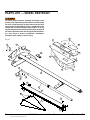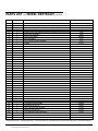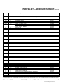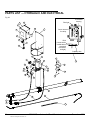
1
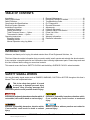
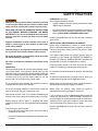
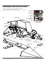
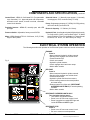
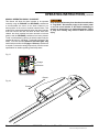
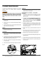
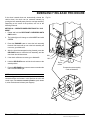
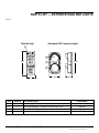
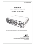
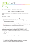
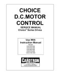
Automatic Wheel Restraint
Surface Mounted
This manual applies to SLSC and
Surface Chock wheel restraints
manufactured beginning December
2013 with the serial number 61098919
and higher.
Do not install, operate or service this product unless
you have read and understand the Safety Practices,
Warnings, and Installation and Operating Instructions
contained in this manual. Failure to do so could result
in death or serious injury.
User’s Manual
Installation, Operations,
Maintenance and Parts
Part No. 6001813Q
table of contents
Introduction..................................................................2
Safety Signal Words ...................................................2
Safety Practices..........................................................3
Components And Specifications..................................4
Electrical System Operation........................................5
Installation Instructions................................................6
Installation Drawing.................................................6
Startup Instructions...............................................10
Trailer Presence Sensor — Option.......................12
Thermostat for Heater — Option...........................13
Operating Instructions...............................................14
Engaging Vehicle..................................................15
Releasing Vehicle.................................................16
Manual Operation using Jog Mode.......................17
Planned Maintenance................................................18
Emergency Release Procedure................................19
Troubleshooting Guide..............................................21
PLC Diagnostics........................................................25
Electrical Schematic .................................................27
Adjustments...............................................................31
Hydraulic Schematic..................................................34
Hydraulic Valve Cross Section..................................35
Power Unit J-Box.......................................................36
Parts List...................................................................40
Warranty Information.................................................51
Distributor Information...............................................52
introduction
Welcome, and thank you for buying this wheel restraint from 4Front Engineered Solutions, Inc.
This User’s Manual contains information that you need to safely install, operate and maintain the wheel restraint.
It also contains a complete parts list and information about ordering replacement parts. Please keep and read
this User’s Manual before using your new wheel restraint.
This manual covers the Serco® SAFETY-CHOCK® and the Kelley® SURFACE CHOCK™ wheel restraints.
safety signal words
You may find safety signal words such as DANGER, WARNING, CAUTION or NOTICE throughout this User’s
Manual. Their use is explained below:
This is the safety alert symbol. It is used
to alert you to potential personal injury
hazards. Obey all safety messages that
follow this symbol to avoid possible death or injury.
Indicates an imminently hazardous situation which, if
not avoided, will result in death or serious injury.
Indicates a potentially hazardous situation which,
if not avoided may result in minor or moderate
injury.
Indicates a potentially hazardous situation which,
if not avoided, could result in death or serious
injury.
Notice is used to address practices not related to
personal injury.
2
©2013 4Front Engineered Solutions, Inc.
6001813Q — Automatic Wheel Restraint
December 2013
safety practices
Read these safety practices before installing, operating
or servicing the wheel restraint. Failure to follow these
safety practices could result in death or serious injury.
READ AND FOLLOW THE OPERATING INSTRUCTIONS
IN THIS MANUAL BEFORE OPERATING THE WHEEL
RESTRAINT. If you do not understand the instructions,
ask your supervisor to teach you how to use the wheel
restraint.
Improper installation of wheel restraint could result in
death or serious injury to dock workers or other users
of the wheel restraint.
Vehicles leaving or moving when loading and unloading
are in process could result in death or serious injury.
Be certain bystanders in the driveway stand clear when
the wheel restraint is operating.
Be certain to follow the installation instructions in this
manual.
OPERATION
Use by untrained people can cause property damage, bodily
injury and/or death. Your supervisor should teach you the
safe and proper way to use the wheel restraint. Read and
follow the complete OPERATING INSTRUCTIONS on page
14 before use. Do not use the wheel restraint if it is not
working right. Tell your supervisor it needs repair.
OPERATION (continued)
After engaging the wheel restraint:
• Load or unload the transport vehicle only when the inside
green light is displayed.
•
If the wheel restraint cannot make engagement, use wheel
chocks to secure the transport vehicle, then turn selector
switch to RESTRAINT OVERRIDE/LIGHTS ONLY.
Pressing the STOP button at any time will stop movement
of the chock.
INSTALLATION, MAINTENANCE AND SERVICE
Before doing maintenance or service be certain that the
power is disconnected and properly tagged or locked out.
Failure to follow these safety practices may result in death
or serious injury.
If the wheel restraint does not operate properly using the
procedures in this manual, BE CERTAIN TO MANUALLY
CHOCK THE VEHICLE WHEELS BEFORE LOADING OR
UNLOADING. Call your local distributor for service.
Place barricades around pit on dock floor and drive while
installing, maintaining or repairing the wheel restraint.
Do not stand in the driveway between the dock and a backing
vehicle.
All electrical troubleshooting and repair must be done by a
qualified technician and meet all applicable codes.
Do not operate the wheel restraint with equipment, material,
or people directly in front of the restraint.
Before doing any electrical work, make certain the power is
disconnected and properly tagged or locked off.
Do not use the wheel restraint if it looks broken or does not
seem to work right. Tell your supervisor at once.
Before doing any welding, make certain the power is
disconnected and properly tagged or locked off.
Keep hands and feet clear of the restraint mechanisms at
all times. Stay clear of the wheel restraint when it is moving.
If it is necessary to make troubleshooting checks inside the
control box with power on, USE EXTREME CAUTION. Do
not place fingers or uninsulated tools inside the control box.
Touching wires or other parts inside the control box could
result in electrical shock, serious injury or death.
Before chocking vehicle wheel or engaging the wheel
restraint, dump air from air ride suspensions and set parking
brake.
Prior to using the wheel restraint:
• Ensure the path of the sensing roller is free and clear of
all debris, ice and snow.
•
Pressing the STOP button at any time will stop movement
of the chock.
Ensure the freight carrier is parked firmly against the dock
bumpers.
December 2013
6001813Q — Automatic Wheel Restraint
©2013 4Front Engineered Solutions, Inc.
3
COMPONENTS AND SPECIFICATIONS
The main components of the wheel restraint are shown
below. See the Parts List for specific part numbers.
Fig. 2
Red light
Amber light
Green light
Engage
Fig. 1
Release
Chock housing
Restraint override/
lights only
Stop
Control panel
Arm spring
Arm spring
adjustment
Arm release
Prop rod
Arm latch
Chock arm
Lock assembly
Carriage guide pin
Hydraulic cylinder
Rail extension
Nose cone
4
©2013 4Front Engineered Solutions, Inc.
6001813Q — Automatic Wheel Restraint
December 2013
COMPONENTS AND SPECIFICATIONS, continued
Control Panel - NEMA 12, Solid state PLC (Programmable
Logic Controller), U.L. approved panel and components,
automatic motor starter, thermal overload, resettable
control circuit breaker.
Proximity Sensors - NEMA 6P, normally open, with LED
pilot light.
Pressure Switch - Adjustable, factory set to 450 PSI.
Motor - NEMA Standard T.E.N.V. / 56C frame, 1 HP (.75 kW),
single or three phase.
Solenoid Valves - (1) Normally open poppet, (1) Normally
closed poppet, 125V, continuous duty, 0.5 amp.
Pump - Single stage gear pump, 2.7 GPM (10.2 LPM), primary
relief valve factory set at 800 PSI.
Reservoir Capacity - 2.7 Gallons (10.2 Liters).
Hydraulic Fluid - An all weather hydraulic fluid with a viscosity
of 15 cSt at 40ºC (100ºF), such as Shell Tellus T 15, Mobil
Aero HFA (49011), Exxon Univis Grade J13, Texaco Aircraft
Oil #1554, U.S. Oil Co., Inc. #ZFI-5606 (Low Temp).
Electrical System Operation
The following describes the operation of the Electrical System when the controls are activated:
Fig. 3
ENGAGE
Press in
• Motor starts and hydraulic cylinder extends.
• Sensing roller engages rear vehicle wheel.
• Pressure switch trips.
• Chock arm extends.
• Hydraulic cylinder retracts.
• Chock engages wheel and motor stops.
• Motion alarm sounds.
RELEASE
Press in
• Motor starts and hydraulic cylinder extends.
• Sensing roller engages rear vehicle wheel.
• Pressure switch trips.
• Hydraulic cylinder and chock arm retract.
• Chock housing returns to the stored position
and motor stops.
• Returns system from lights only (Restraint Override/Lights Only) to normal operating
condition.
• Motion alarm sounds.
RESTRAINT OVERRIDE/LIGHTS ONLY
Turn clockwise (spring return)
• Turn selector to right and release.
• Power is cut off from motor control circuit.
• Power is supplied to outside red light and
inside green and amber lights.
RESTRAINT STOP
Press in
• Power is cut off from motor control circuit.
• Pull out to resume normal operations.
December 2013
6001813Q — Automatic Wheel Restraint
©2013 4Front Engineered Solutions, Inc.
5
installation INSTRUCTIONS
Fig. 4
Before installation read and follow the Safety Practices
on page 3. Failure to follow these safety practices could
result in death or serious injury.
Point “A”
READ AND FOLLOW THE OPERATION INSTRUCTIONS
IN THIS MANUAL BEFORE OPERATING THE wheel
restraint. If you do not understand the instructions,
ask your supervisor to teach you how to use the wheel
restraint.
3/4"
concrete
anchors
(3)
Point “B”
Improper installation of the wheel restraint could result
in death or serious injury to dock workers or other users
of the wheel restraint.
146"
Be certain bystanders in the driveway stand clear when
the wheel restraint is operated.
52" to bottom
edge of
tube. typ
Be certain to follow the installation instructions in this
manual.
Installation Instructions
1. Layout the installation position. Refer to the wheel
restraint installation drawings included in this publication
for clarification of the following instructions. See Fig. 4.
NOTE:
For units with remote roller guard, refer to the formal approval
drawing specific to the site.
27'-7"
Ref
Point “C”
3/4" concrete
anchors (2)
Dock centerline
Place barricades around pit on dock floor and drive while
installing, maintaining or repairing the wheel restraint.
155"
a. Mark the center line of the dock on the driveway. This
is point “A”.
b. While facing the dock, measure over 52" to the left
of the center line and mark the driveway at the dock
wall. This is point “B”.
c. Measure 146" out from the dock wall (from point “B”)
and draw a line on the driveway parallel to the wall.
d. Hold one end of the tape measure on the center line
of the dock wall (point “A”) and measure out 155" to
the 146" line. Mark where the 155" distance crosses
the 146" line. This is point “C”.
e. Mark a line from point “B” to point “C” and extend the
line out 26' from the dock face. This line will be square
to the dock wall.
6
©2013 4Front Engineered Solutions, Inc.
3/4" concrete
anchors (2)
PLAN VIEW
6001813Q — Automatic Wheel Restraint
Door centerline to
door centerline
minimum 11'-6" required
December 2013
installation INSTRUCTIONS, continued
2. Position the wheel restraint assembly against the wall and
on the left side of the driveway with the inside edge of the
guide rail tube directly above the line “B-C”. Secure the
rail assembly to the driveway with five anchor bolts 3/4"
diameter by 5-1/2" long (Furnished by 4Front Engineered
Solutions, Inc.). Do not anchor bolt to the building wall.
Torque to 110 ft. lbs.
3. Mount the optional remote roller guard and spacer. Secure
the remote roller guard and spacer with 3/4" x 5-1/2" long
anchor bolts. See Fig. 5.
Fig. 5
Standoff
8-1/2" Min.
12-3/8"
Remote roller guard
14-5/8"
4. Using the carriage bolts supplied, attach the rail extension
to the front of the rail and to the nose cone. Do not tighten
the bolts. Line up the rail extension with the line “B-C”.
5. Remove the covers from the nose cone and mark the
location of the two mounting holes on the pavement.
Remove the nose cone and drill the holes for the anchor
bolts.
6. Secure the nose cone to the driveway with two anchor bolts
3/4" diameter by 5-1/2" long. Tighten the rail extension
bolts and replace the covers on the nose cone.
7. Mount the hydraulic power unit inside the building near the
end of the rail assembly. Install a 2-1/2" diameter duct for
hydraulic hoses from the power unit to the wheel restraint.
Install conduits for electric wires if required by local codes.
(The wires are for the 24 VDC proximity switches, and for
the optional 120 VAC heater.)
8. Mount the control panel on drivers side of the dock so
that the communication lights are visible to the fork truck
driver. Mount the outside communication lights and sign
so that they are visible to the vehicle driver. Mount the
motion alarm on the same side as the restraint using
the provided mounting bracket. Refer to the installation
drawing for recommended dimensions. Make sure the
Red light is on top and the Green light on the bottom
when the light assembly is mounted. See Fig. 6.
December 2013
6001813Q — Automatic Wheel Restraint
©2013 4Front Engineered Solutions, Inc.
7
installation INSTRUCTIONS, continued
The chock motion alarm assembly must be located in
the area of the chock on the outside wall. A bracket is
provided for outside wall mounting. Failure to mount
the alarm outside in close proximity with the chock may
reduce its effectiveness which could result in death or
serious injury. The motion alarm assembly is designed
and controlled to sound whenever the chock is in
motion.
All wiring must be done by a qualified technician and
must meet all applicable codes.
10. Make all connections as shown on electrical installation
drawings, see pages 27-30 and 36-38. This includes
power into the control panel from a fused disconnect,
wiring from panel to motor, hydraulic power unit, outside
lights, outside motion alarm, solenoid valve, pressure and
proximity switches, and options such as trailer presence
indicator and heat tape. This would also include any
interlocking between components such as to a vertically
storing dock leveler.
11. Attach the ends of the two supplied hydraulic hoses to the
power unit fittings as shown on page 44 of this manual.
Seal the unattached ends with tape so dirt and foreign
material cannot enter the hoses. Route the hoses through
the 2-1/2" duct to the outside and connect the free ends
of the hoses together. Do not connect the hoses to the
hydraulic cylinder at this time.
NOTE:
Do not connect the hoses to the hydraulic cylinder until all
air has been bled. Air in the hydraulic system will cause
jerky operation requiring the system to be bled. Use bleed
procedure shown on page 18.
8
©2013 4Front Engineered Solutions, Inc.
6001813Q — Automatic Wheel Restraint
December 2013
installation INSTRUCTIONS, continued
Fig. 6
Motion alarm
(mounted under
wall bracket
to outside
wall above
chock assembly)
Lights and sign
supplied by 4Front.
(installed by others)
3/4" ID conduit
for control wiring
(by others)
2-1/2" ID duct
for hydraulics
and heater
cable (by others)
90"
Grade line
Hydraulic power unit
for wheel restraint
OUTSIDE VIEW
3/4" ID conduit power
supply for wheel restraint
(by others)
SIDE VIEW
Typical control installation
1" ID conduit for safety chock
24VDC control voltage and
120VAC panel supply voltage
(by others)
Wheel restraint control panel
(supplied by 4Front)
(installed by others)
48"
All conduit and
electrical interconnection
by others
Hydraulic power unit assembly
(supplied by 4Front)
(installed by others)
60"
INSIDE WALL VIEW
December 2013
6001813Q — Automatic Wheel Restraint
©2013 4Front Engineered Solutions, Inc.
9
installation instructions, continued
12. Obtain the adjustment bolts from the shipping tube for the
sensor roller arm and install the roller arm on the pivot
pin. See Fig. 7. Adjust the sensor arm to 32". See page
31. When adjustment is complete, secure the position of
the adjusting bolts with jam nuts. Do not overtighten the
adjusting bolts.
Before installation read and follow the Safety Practices
on page 3. Failure to follow these safety practices could
result in death or serious injury.
Before doing any electrical work, make certain the power
is disconnected and properly tagged or locked off. All
electrical work must be done by a qualified technician
and meet all applicable codes. If it is necessary to make
troubleshooting checks inside the control box with the
power on, USE EXTREME CAUTION. Do not place your
fingers or uninsulated tools inside the control box.
Touching wires or other parts inside the control box
could result in electrical shock, death or serious injury.
Wheel Restraint — Startup Instructions
1. Refer to the manual for operation instructions and location
of components in the control panel. Remove the 3/8 NPT
plug from the hydraulic reservoir and install the breather
cap.
2. Turn on the electrical power to the wheel restraint. Open
the control panel and locate the LED indicators for the
Inputs and Outputs. Input 0 should be on. If not, ensure
the circuit breaker is on and check wiring to the pressure
switch. (Pressure switch NC [normally closed] contacts
are used).
3. Because the proximity switch inputs 1 and 2 are not on,
the control will be in “Jog Mode” and the inside amber
light will flash. The operator will be able to manually control
the motor using the Engage and Release buttons in
“Jog Mode”. See “Jog Mode” instructions on page 16.
5. Press the Release button and hold it for at least 15
seconds to run the pump and force the air out of the
hoses. Then turn off electrical power to the panel.
6. Place a container under the hydraulic cylinder ports to
catch any fluid which may leak from the hoses during step
7. Refer to the hydraulic installation drawing to identify
the “E” and “R” ports of the cylinder.
7. Disconnect the hoses from each other and attach the
hoses to the hydraulic cylinder. Try to minimize fluid loss
and air entry, while connecting the hoses.
8. Check that the hydraulic fluid is showing on the breather
dip stick in the reservoir. Add fluid if required.
NOTE:
An assistant is required for the following operations. Refer to
the Test Drawing on page 11 for clarification of instructions.
Keep hands and feet away from the pinch points at the
ends of the test bar when chock is moving. Keep away
from the path of the chock arm when using the test bar.
9. Select a piece of lumber stock (or other suitable bar) about
6' long. This “test bar” will be used to simulate contact with
a wheel during the startup procedure. Place one end of
the test bar against the back of the front mounting post of
the guide rail and the other end in the path of the washer
on the sensing roller. Refer to Fig. 8.
10. Ensure driveway is clear before operating the wheel
restraint. Then turn on the electrical power to the wheel
restraint.
Fig. 7
4. Press the Engage button and hold it for no more than
10 seconds. Input 3 LED should go off and the gauge
should indicate pressure from the pump. If there is no
indication of pressure and the electrical power is three
phase, reverse the wires to terminals Tl and T2. Repeat
step 4.
10
©2013 4Front Engineered Solutions, Inc.
6001813Q — Automatic Wheel Restraint
December 2013
installation instructions, continued
Fig. 8
Chock arm will swing out of housing when test bar
contacts roller arm. Keep clear.
11. Turn and hold the selector switch on the control panel to
the RESTRAINT OVERRIDE/LIGHTS ONLY position.
Press and hold the ENGAGE button to extend the chock
housing away from the dock. The inside red light should
be flashing to indicate “Jog Mode”. Continue holding the
button until the sensing roller contacts the rear end of
the test bar and the chock arm extends fully. Then press
the Release button to retract the chock housing and
release the test bar.
12. Referring to page 31, adjust the bolts for the sensor roller
arm until the front of the roller is 32" from the surface of the
chock as shown. Tighten the adjustment bolts gently, only
enough to hold the pin in place, and then tighten the jam
nuts securely. DO NOT overtighten the adjustment bolts.
Test bar
13. Turn the selector switch clockwise and hold it in the
RESTRAINT OVERRIDE/LIGHTS ONLY position. Press and
hold the RELEASE button to bring chock assembly toward
the wall, Have the assistant hold the test bar with the rear
end against the dock wall so the chock will contact the front
of the test bar and the chock will be locked in position. See
Fig. 8.
14. While holding the selector switch in the RESTRAINT
OVERRIDE/LIGHTS ONLY position, press and hold the
ENGAGE button to free the test bar. Then press and hold
the RELEASE button. The chock arm should retract into the
housing. If it does not, then place the test bar against the
back of the mounting post of the guided rail as described
on step 9 so it will be in the path of the sensing roller. Then
extend the chock assembly until it is stopped by the sensing
roller against the end of the test bar. See Fig. 8.
Test bar
15. While holding the selector switch in the RESTRAINT
OVERRIDE/LIGHTS ONLY position, press and hold the
RELEASE button and the chock arm will retract into the
housing. Continue holding the RELEASE button until the
chock assembly is in the stored position against the wall.
16. When the wheel restraint is in the stored position against
the dock wall, the amber lamp will continue to flash if an
error code has been set (automatic jog mode). Press the
RELEASE push-button to clear this condition and return to
normal operation.
December 2013
Chock arm will swing out of housing when test bar
contacts roller arm. Keep clear.
6001813Q — Automatic Wheel Restraint
©2013 4Front Engineered Solutions, Inc.
11
installation instructions, continued
17. To verify automatic operation of the wheel restraint,
a. Place the test bar against the back of the front mounting
post of the guided rail so it will be in the path of the
sensing roller.
Fig. 9
Building wall
b. Press the Engage button. The chock assembly
will travel outward on the rail until the sensing roller
contacts the rear of the test bar and the chock arm is
fully extended. The housing will then reverse.
Top View
c. Have the assistant hold the test bar with the rear end
against the dock wall so the chock will contact the front
of the test bar. When the chock contacts the end of the
test bar, the power unit will stop and the test bar will be
locked against the wall.
d. Press the Release button. The chock assembly will
travel outward on the rail for several seconds and will
then reverse. The chock arm should retract. The chock
housing will continue to reverse until it stops against
the dock wall. If the chock arm does not retract, block
sensor arm rollers forward motion until carriage (item
1) and lock (item 2) separate.
Note: Rotate head 5°
from center
3-4477
Center line of door opening
18. Refer to the operation and maintenance instructions. If
the wheel restraint does not operate properly, refer to the
troubleshooting guide on pages 19-21.
trailer presence sensor (optional)
The trailer present sensor senses a vehicle at the dock and
transmits a signal to the control panel. This turns on the panel
face AMBER light. Mount the sensor. See Fig. 9. Ensure the
sensor’s logic switch is set to L/O (Light Operate). The switch
is located on the top of the sensor under a plastic cover. Wire
the switch. Wire the sensor into the panel per the per the
job specific schematic located in the panel. Test for proper
operation as per below.
1. For vehicle presence sensor installed termination, see
schematic included in panel.
a. The sensor is a 4 wire device. First terminate the
positive lead (brown wire) to any “C” terminal on the
input board.
Conduit
to control
panel
Front View
Building wall
34"- 48" ref.
315-370
C
E
1/2"
rigid
conduit
with
15°
bend
14' - 6' minimum
above grade
Side View
b. Terminate the negative lead (blue wire) to any “0V”
terminal in the panel.
c. Terminate the load lead (black wire) to the terminal
specified in the job specific wiring schematic.
d. Tape (insulate) the unused white wire.
12
©2013 4Front Engineered Solutions, Inc.
6001813Q — Automatic Wheel Restraint
December 2013
installation instructions, continued
OPERATIONS
No Trailer Present
• Inside lights display Solid RED outside display GREEN.
Fig. 10
Pilot light
Trailer Arrives
• Inside lights switch to Solid AMBER and RED, outside
lights continue to display GREEN.
Operator engages vehicle restraint
• Inside lights switch to Solid GREEN, outside lights switch
to display RED.
Operator releases vehicle restraint
• Inside lights switch to Solid AMBER and RED, outside
lights continue to display GREEN.
Trailer Departs
• Inside lights display Solid RED outside display GREEN.
HEATER (optional)
1. On the inside of the wall, mount the thermostat housing on
the chock side of the door opening and in close proximity
to the outside alarm. Protrude the bulb through the wall
and under the outside alarm to protect the bulb from direct
sunlight.
Thermostat
housing
Cover removed
for clarity.
Bulb
(Locate under
outside alarm
protected
from direct
sunlight)
Capillary tube
2. Wire the heating element into the thermostat housing.
Power for the heating element is to be wired from the
control panel to a circuit breaker and GFI protection in the
power unit junction box, then to the thermostat housing
and then to the heating element as shown in the power
unit junction box wiring diagrams on pages 37-38.
3. Set the thermostat 10°F lower than the current outside
temperature. Test the heating element and chock for
proper operation. Reset the thermostat to 40°F or desired
activation temperature.
December 2013
6001813Q — Automatic Wheel Restraint
©2013 4Front Engineered Solutions, Inc.
13
operating instructions
Use these instructions for normal operations.
Before operating the wheel restraint, read and follow the
Safety Practices, Warnings, and Operation instructions
contained in this manual. Use by untrained people could
result in death or serious injury.
Do not use the wheel restraint if it looks broken or does
not seem to work right. Tell your supervisor at once.
Keep hands and feet clear at all times. Stay clear of the
wheel restraint when it is moving.
Do not load or unload any vehicle unless you make
certain the wheel restraint has securely engaged the
tire and set the brakes. If the wheel restraint does not
chock the vehicle's tire for any reason, BE CERTAIN TO
MANUALLY CHOCK THE VEHICLE WHEELS BEFORE
LOADING OR UNLOADING.
Enter the vehicle only when the green signal light on
the control panel is on. You must check the green
signal light each time that the vehicle is entered. If
the green light goes off at any time during loading
operations, immediately cease loading operations and
check the wheel restraint to ensure that it is securely
hitched.
If the power to the wheel restraint is interrupted,
immediately cease operations and check the unit.
Consult the troubleshooting instructions to reset the
lights when power resumes.
Vehicles leaving or moving when loading and unloading
are in process could result in death or serious injury.
Failure to follow these safety practices may result in
death or serious injury.
Pressing the STOP button at any time will stop movement
of the chock.
14
©2013 4Front Engineered Solutions, Inc.
6001813Q — Automatic Wheel Restraint
December 2013
operating instructions, continued
Engaging Vehicle
1. When the wheel restraint is stored, the outside green
light and inside red light will be on.
Fig. 11
2. To secure the vehicle at the dock, press the ENGAGE
button. The outside lights immediately change from
green to red, and the chock housing will start to move
away from the wall. The chock housing will continue
moving outward until the sensing roller contacts the rear
wheel of the vehicle.
Red
Green
3. When the sensing roller contacts the rear wheel of the
vehicle the chock arm will extend out of the housing until
it is placed in front of the rear wheel. When the chock is
fully extended, the chock housing will reverse and move
the wheel chock back to firmly engage the wheel. The
inside lights will change from red to green. The vehicle
is now safe to load or unload.
Fig. 12
Red
Red
When the wheel restraint has engaged a wheel, the
hydraulic pump will automatically start and maintain
engagement pressure against the wheel if the vehicle
moves. Disconnect power to the control panel or turn
the circuit breaker to OFF before attempting to make
adjustments. Failure to keep clear may result in personal
injury.
Press to engage
Fig. 13
Green
Red
December 2013
6001813Q — Automatic Wheel Restraint
©2013 4Front Engineered Solutions, Inc.
15
operating instructions, continued
Releasing Vehicle
4. To release the vehicle from the dock, press the RELEASE
button. The inside lights immediately change from green
to red and the chock housing will begin to move forward.
When the chock is clear of the wheel, the housing will
reverse, the chock arm will retract into the housing and
continue to move toward the wall.
Fig. 14
Red
Red
5. When the housing has moved back to the wall, the outside
lights will change from red to green. The vehicle is
now free to leave.
For Vehicles which cannot be Engaged
If the configuration of the vehicle wheels prevents proper
engagement of the wheel chock, the carriage may return to
the home position and report a Vehicle Not Found condition.
This condition is reported by flashing the inside red and
amber lamps. Manually chock the vehicle wheels and then
rotate the RESTRAINT OVERRIDE/Lights Only selector
switch to initiate a lights override condition. The outside red
lamp and inside green and amber lamps will illuminate.
The vehicle is now safe to load/unload. When loading/
unloading is complete, remove wheel chocks and press
Release. The outside green lamp and inside red lamp
will illuminate.
Press to release
Fig. 15
Red
Green
Fig. 16
Amber
Green
Red
Wheels chocked
Switch to RESTRAINT
OVERRIDE/Lights Only
16
©2013 4Front Engineered Solutions, Inc.
6001813Q — Automatic Wheel Restraint
December 2013
operating instructions, continued
Manual Operation using “Jog Mode”
This feature will allow the wheel restraint to be operated
manually using the Engage and Release push-buttons
to accommodate the return of the wheel restraint to its
home position in the event of a wheel restraint failure. This
mode will be entered automatically when the wheel restraint
fault has occurred and will exit when all faults have been
cleared, the wheel restraint has been returned to its home
position and the Release push-button has been pressed.
To aid in troubleshooting efforts, the wheel restraint may be
intentionally put into “Jog Mode”. To manually initiate the “Jog
Mode”, turn and hold the Restraint Override/Lights Only
switch and press either the Engage or Release push-buttons
to extend or retract the carriage respectively. See the control
specification for details regarding panel lamp status.
Keep hands and feet away from the wheel restraint when
in “Jog Mode”. Disconnect power to the control panel
or turn the circuit breaker to OFF before attempting to
remove an obstruction or to make adjustments. Failure
to obey this warning may result in death or serious
injury.
Fig. 17
Engage
Release
Retract
Fig. 18
Extend
December 2013
6001813Q — Automatic Wheel Restraint
©2013 4Front Engineered Solutions, Inc.
17
planned maintenance
To ensure the continued proper operation of your wheel
restraint, perform the following planned maintenance
procedures.
Do not service this product unless you have read and
followed the Safety Practices, Warnings and Operation
instructions contained in this manual. Failure to follow
these safety practices could result in death or serious
injury.
daily
1. Clear all debris (dirt, snow, etc.) from the path of the
sensing roller.
2. Check for worn, torn, or missing dock bumpers. Replace
if necessary.
3. Check that all lights on the control panel and both outside
lights and alarm are functioning.
weekly
1. Remove all debris from the chock parking area and under
the wheel restraint housing.
quarterly
1. Check the level of fluid in the hydraulic reservoir. Oil level
shall be within 3-1/2 inches of the fill port with restraint in
stored position.
2. Lubricate the arm latch and arm release bearings and the
mating faces of arm latch and arm release with light oil.
Ensure that they pivot freely. See Fig. 19.
3. Inspect the mechanism for any signs of wear, distortion,
or cracked welds.
annually
1. Check for proper operation of the heat tape (when installed)
yearly before the cold weather.
SLSC Hydraulic Cylinder — Filling and
Bleeding
1. Verify that the reservoir fluid level is within 3-1/2 inches
of the fill port with the restraint in the stored position,
against the wall.
2. For all of the operations described below, run the pump in
“Jog Mode”. Turn the RESTRAINT OVERRIDE selector
switch clockwise and hold it. Then press the ENGAGE
button to extend the cylinder or press the RELEASE
button to retract the cylinder.
3. Extend the cylinder 4 to 6". Rotate the cylinder to place
the bleed screw facing up in an accessible position. It may
be necessary to loosen the cylinder support (see items
29 and 43 on page 40).
4. Using a 5/32" hex key, loosen the bleed screw two full
turns.
5. With a drip pan under the bleed screw, retract the cylinder
until clear fluid starts to flow from the bleed screw.
6. Refill the reservoir with fluid (see quarterly step 1).
7. Fully extend the cylinder while holding the drip pan under
the bleed screw.
8. Tighten the bleed screw, then wipe fluid from all surfaces.
9. Retract the cylinder and watch for any fluid leaking from
the bleed screw.
4. Check all decals and outside sign. Replace as needed.
Fig. 19
18
©2013 4Front Engineered Solutions, Inc.
6001813Q — Automatic Wheel Restraint
December 2013
emergency release procedure
If the wheel restraint does not automatically release the
vehicle wheel, the chock can be retracted manually by
moving the lock assembly away from the carriage assembly.
Depending on the cause of the problem, use one of the
following methods.
Fig. 20
Method A — Operate Wheel restraint in “Jog
Mode”
1. Rotate and hold the Restraint Override/Lights
Only switch.
2. The inside lights will change to solid amber and solid
green.
3. Press the ENGAGE button to move the lock assembly
forward. If the motor will not run or the lock assembly will
not move, go to Method B.
4. After the chock has stopped moving forward, press the
RELEASE button to retract the lock assembly, and the
chock arm should also retract.
5. If the chock still does not retract, go to Method B.
6. Hold the RELEASE button until the chock returns to the
stored position.
SV2
SV1
R port
retract
7. Press the RELEASE button once to return to normal mode
with a constant red light.
Pump and motor assembly
used on Method B
NOTE:
To manually release the restraint, push button in, twist
counterclockwise and release. In this position the valve will
remain open. To return to normal operation, push button
in, twist clockwise and release (see diagram).
December 2013
6001813Q — Automatic Wheel Restraint
©2013 4Front Engineered Solutions, Inc.
19
emergency release procedure, continued
Method B —
Manually release the hydraulic pressure
(no electric power at dock)
1. Turn circuit breaker OFF inside control panel.
5. When the lock wedge is clear of the chock, the chock arm
will start to retract. The sensing roller will contact the back
of the wheel and prevent the chock from fully retracting.
As the vehicle slowly moves forward, the wheel will move
away from the roller and the chock will fully retract.
2. Open the manual release knob on the hydraulic
solenoid valve SV1. This will open the valve, release
pressure and allow fluid to escape from the hydraulic
cylinder. See Fig. 20.
6. If the wheel restraint cannot be restored to normal
operation, or cannot be moved to the stored position,
remove the roller arm pin and the sensing roller arm to
prevent damage by the next vehicle.
3. Raise the cover of the wheel restraint. Place a pry bar
between the release plates on the chock arm and lock
assembly as shown in Fig. 21.
7. Return the pressure relief valve to the closed position
before operating pump.
4. Pull on the pry bar until the lock wedge moves past the
end of the chock arm.
Fig. 21
Pull
Release plates
Pry bar
Roller arm pin
20
©2013 4Front Engineered Solutions, Inc.
6001813Q — Automatic Wheel Restraint
December 2013
troubleshooting guide
Use the Troubleshooting Guide if ever the wheel restraint
fails to perform properly. Find the condition that most closely
matches your situation, and make the recommended
adjustments.
The functions of the wheel restraint are controlled by a
Programmable Logic Controller (PLC) which has LED
indicator lights to display errors and the state of input and
output signals.
Fig. 22
PLC
Do not service this product unless you have read and
followed the Safety Practices, Warnings and Operation
instructions contained in this manual. Failure to follow
these safety practices could result in death or serious
injury.
Before doing any electrical work, make certain the power
is disconnected and properly tagged or locked off. All
electrical work must be done by a qualified technician
and meet all applicable codes. If it is necessary to make
troubleshooting checks inside the control box with the
power on, USE EXTREME CAUTION. Do not place your
fingers or uninsulated tools inside the control box.
Touching wires or other parts inside the control box
could result in electrical shock, death or serious injury.
Input connections
0 1 2
3 4 5 6
7 8 9 10 11 12 13
Telemecanique
Input/output
display
0 1 2
Memory cartridge port
PROBLEM
3
4 5
6 7
8
Output connections
9
24 VDC INPUT
POSSIBLE CAUSE
SOLUTION
A) Motor does not run.
1. No lights on control panel. No
PLC LED indicator lights.
December 2013
a) No power to control panel.
a) Check for primary power at terminals
L1, L2 and L3 (L and N on single phase
units).
b) Blown fuse(s).
b) Check fuse FU1002. Replace if faulty.
c) Blown transformer primary fuse(s).
c) Check transformer primary fuses,
replace if necessary.
6001813Q — Automatic Wheel Restraint
©2013 4Front Engineered Solutions, Inc.
21
troubleshooting guide, continued
Use the Troubleshooting Guide if ever the wheel restraint
fails to perform properly. Find the condition that most
closely matches your situation and make the recommended
adjustments. Observe all safety warnings before attempting
any maintenance procedure.
PROBLEM
Before servicing the wheel restraint, read and follow the
Safety Practices on Page 3 and the Operation section in
this manual.
POSSIBLE CAUSE
SOLUTION
2. Some lights on control panel face.
No PLC LED output lights on.
a) Program faulty.
a) Reload program - Consult factory.
3. Motor starter does not engage.
a) Incorrect wiring.
a) Check for 120 VAC to solenoid valves.
b) Hoses Reversed.
b) Check for proper routing of hoses to
pump ports.
c) Fuse FU1011 faulty.
c) Check FU1011. Replace if faulty.
d) Pressure relief valve open.
d) Check the manual release on solenoid
valve 2 (SV2). Make sure manual valve
is closed. See Fig. 20.
e) Solenoid valve problem.
e) If voltage is present, check valves and
solenoid coils.
f) Hydraulic pump problem.
f) If input 3 does not go off, check
hydraulic pump.
4. Motor starter engages, but
motor does not run, or runs
poorly.
a) Missing power phase (3 phase
motor).
a) Check for voltage across L1-L2, L1-L3,
L2-L3. All 3 measured voltages should
be nominally equal. If not, check power
source.
Highly recommend disconnecting
the motor leads in the control
panel prior to performing tests
in this section. Contactor and
overload relays will be damaged
if connected to a short circuit.
b) Damaged contactor.
b) With contactor energized, check for
voltage across contactor terminals
T1-T2, T1-T3, T2-T3. All 3 measured
voltages should be nominally equal. If
not, replace contactor.
c) Damaged overload relay.
c) Repeat as above, but measure
voltages across overload terminals T1T2, T1-T3, T2-T3. If voltage is okay at
contactor - overload interface, but not
at overload terminals T1-T2-T3, replace
overload relay.
22
©2013 4Front Engineered Solutions, Inc.
6001813Q — Automatic Wheel Restraint
December 2013
troubleshooting guide, continued
Use the Troubleshooting Guide if ever the wheel restraint
fails to perform properly. Find the condition that most
closely matches your situation and make the recommended
adjustments. Observe all safety warnings before attempting
any maintenance procedure.
PROBLEM
5. Motor runs but chock housing
does not extend.
December 2013
Before servicing the wheel restraint, read and follow the
Safety Practices on Page 3 and the Operation section in
this manual.
POSSIBLE CAUSE
SOLUTION
d) Wiring faulty.
d) Disconnect motor wires at motor. With
motor wires connected in control panel,
check for voltage across T1-T2, T1-T3,
T2-T3. If voltage is not okay but voltage
is okay in control panel, replace wiring.
e) Motor faulty.
e) If all previous tests are okay and motor
does not run, replace motor. Note:
Motor rotation must be correct. Refer to
startup instructions on page 9.
a) Motor rotation incorrect.
a) Reverse motor rotation by reversing
any 2 of the three 3-phase motor
supply wires.
b) Incorrect wiring.
b)Check for 120 VAC to solenoid valves.
c) Fuse FU1011 faulty.
c) Check fuse FU1011. Replace if faulty.
d) Solenoid valve problem.
d) If voltage present, check valves and
solenoid coils.
e) Hydraulic pump problem.
e) If input 3 does not go off, check
hydraulic pump.
f) Manual release knob (SV1) is open.
f) Push knob in and rotate clockwise.
See Fig. 19.
6001813Q — Automatic Wheel Restraint
©2013 4Front Engineered Solutions, Inc.
23
troubleshooting guide, continued
Use the Troubleshooting Guide if ever the wheel restraint
fails to perform properly. Find the condition that most
closely matches your situation and make the recommended
adjustments. Observe all safety warnings before attempting
any maintenance procedure.
PROBLEM
Before servicing the wheel restraint, read and follow the
Safety Practices on Page 3 and the Operation section in
this manual.
POSSIBLE CAUSE
SOLUTION
a) Sensing roller problem.
a) Check that the chock does not strike
the side of the wheel as it extends
Adjust roller arm if necessary.
b) Pressure switch problem.
b) Adjust pressure switch setting to 450
PSI. Replace if faulty.
c) Arm Latch and Release weldments
not pivoting freely.
c) Lubricate weldment pivots and the
edges where these two parts make
contact. See page 18, Quarterly
Maintenance.
7. Chock will not engage or
disengage.
a) Carriage guide rollers are incorrectly
adjusted, and not rolling smoothly.
a) Adjust all cam rollers so that the
carriages slide smoothly on the rail.
Clean, lubricate and adjust cam rollers.
8. Motor runs and chock housing
moves, but chock arm assembly
will not release wheel.
a) Chock wedging on front of wheel.
a) Check that the sensing roller is not too
close to the back of the wheel. Adjust
roller arm if necessary.
b) "Extend Latch" did not release.
b) Re-engage the wheel, using “Jog
Mode” if required. Disconnect electrical
power and inspect latch.
a) Fuse FU1005 faulty.
a) Check fuse FU1005. Replace if faulty.
b) LED(s) burnt out.
b) Check LED(s) in outside lights.
Replace if faulty.
a) LED(s) burnt out.
a) Check LED(s) in panel face lights. Replace if faulty.
6. Chock housing moves, but
chock arm does not fully
extend.
9. No outside lights on.
10. Restraint operates properly.
Some PLC LED indicator lights
on. No lights on control panel
face.
24
©2013 4Front Engineered Solutions, Inc.
6001813Q — Automatic Wheel Restraint
December 2013
PLC Diagnostics
Control Panel — LED Display
The wheel restraint is controlled by a solid-state
programmable logic controller (PLC) which reads input
signals from the push-buttons and proximity sensors, and
closes the appropriate output relays to the motor and to the
warning lights.
Input Signals
0 - Restraint Override/Lights Only not selected
1 - PRS1: Carriage Retracted proximity sensor ON
2 - PRS2: Chock Arm Retracted proximity sensor ON
3 - PS1: N/C Pressure switch OFF
4 - Reserved
5 - Reserved
6 - Engage button depressed
7 - Release button depressed
8 - Door opened (N/A for standard panel applications)
9 - Door closed
10 - Leveler stored proximity sensor ON
11 - Reserved
12 - Snugging enabled
13 - Stop button pulled out
Output Signals
0 - Inside Red lamp ON
1 - Inside Amber lamp ON
2 - Inside Green lamp ON
3 - Outside Green lamp relay ON
4 - Solenoid valves ON (carriage moving forward)
5 - Reserved
6 - TNF Alarm (pulsed output; optional)
7 - Motor
8 - Motion Alarm (pulsed output)
9 - Leveler Interlock (restraint engaged and door opened if
applicable)
Diagnostics Mode — PLC LED Display
The PLC continuously monitors system operation and will
indicate when it is malfunctioning. If an error occurs that could
be potentially dangerous, the restraint will halt operation and
the inside panel lamps will display an indication of the error.
If a restraint fault has occurred:
• Inside Red lamp is on.
• Inside Amber lamp is flashing a trouble code.
• Jog mode is automatically activated.
To identify the specific problem, count the flashes of the
Amber lamp and compare the number to the table below.
The count sequence will be repeated until the cause of the
restraint fault is corrected and the Release push-button is
pressed. A two second pause between flash sequences is
employed.
Trouble Code Definitions
Trouble CodeTrouble Definition
2
3
4
5
6
7
December 2013
Did not lose LS1, LS2 and PS1 after leaving the home position
Possible obstruction encountered while retracting or an LS failure
PS1 failed open or carriage has traveled to far end of the rail
Motor run timeout exceeded
LS present while carriage locked or moving forward
Loss of LS’s while restraint is home
6001813Q — Automatic Wheel Restraint
©2013 4Front Engineered Solutions, Inc.
25
PLC Diagnostics, continued
Operating Mode — PLC LED Display
CONTROLLER FAULT CONDITIONS
RUN LED (Green)
Application not executed
Controller is in RUN mode
Controller is in STOP mode, or execution fault (HALT)
ERR LED (Red)
OK
Internal faults (watchdog, etc.)
Application not executable, or execution error (HALT)
LED Indicators
NORMAL OPERATING SEQUENCES
HOME
Carriage fully retracted (stored)
STEP 1
Initial departure
STEP 2
Carriage extending
STEP 3
Carriage retracting
Telemecanique Twido PLC, model no.
TWDLCAA24DRF. Compact base unit, 230V
AC, with 14" (24V DC), 10 out (2A relays).
Screw terminal blocks, non-removable.
STEP 4
Chock fully engaged
(tire gripped)
STEP 5
Carriage extending
(releasing)
STEP 6
Carriage retracting (releasing)
LEGEND
LED OFF
LED ON
LED Flashing
LED ON or OFF (either condition
may be present during the course
of given sequence)
26
©2013 4Front Engineered Solutions, Inc.
TNF
Truck not found
RESTRAINT OVERRIDE
Restraint override condition
6001813Q — Automatic Wheel Restraint
December 2013
electrical schematic
Fig. 23
NOTE:
Power to control panel must be from fused
disconnect supplied by others. Max (Type
CC) fuse size shown above.
December 2013
Before doing any electrical work, make certain the power
is disconnected and properly tagged or locked off. All
electrical work must be done by a qualified technician
and meet all applicable codes. If it is necessary to make
troubleshooting checks inside the control box with the
power on, USE EXTREME CAUTION. Do not place your
fingers or uninsulated tools inside the control box.
Touching wires or other parts inside the control box
could result in electrical shock, death or serious injury.
6001813Q — Automatic Wheel Restraint
©2013 4Front Engineered Solutions, Inc.
27
electrical schematic, continued
Fig. 24
NOTE:
Power to control panel must be from fused
disconnect supplied by others. Max (Type
CC) fuse size shown above.
28
©2013 4Front Engineered Solutions, Inc.
6001813Q — Automatic Wheel Restraint
December 2013
electrical schematic, continued
Fig. 25
NOTE:
Power to control panel must be from fused
disconnect supplied by others. Max (Type
CC) fuse size shown above.
December 2013
6001813Q — Automatic Wheel Restraint
©2013 4Front Engineered Solutions, Inc.
29
electrical schematic, continued
Fig. 26
Control Panel
30
©2013 4Front Engineered Solutions, Inc.
6001813Q — Automatic Wheel Restraint
December 2013
adjustments
Use these instructions to adjust the wheel restraint.
Do not service this product unless you have read and
followed the Safety Practices, Warnings and Operation
instructions contained in this manual. Failure to follow
these safety practices could result in death or serious
injury.
Fig. 27
Proximity Sensors — PRS1 and PRS2
Two proximity sensors are used to sense the various
positions of the wheel restraint. The sensors are solid state
proximity sensors which close an electrical circuit when they
sense the presence of a steel target. The locations of these
sensors are shown below. To access these sensors, first
remove the cover at the rear of the chock rail by removing
the two screws which hold it into place. Before adjusting
either PRS1 or PRS2, be sure that the pivot carriage is
fully retracted. Adjust the position of the proximity sensors
using two 15/16" open end wrenches to loosen the holding
nuts. Then adjust the proximity sensor inward or outward as
shown and tighten the nuts to 11 ft/lbs to secure the sensor.
The face of the proximity sensor should be 1/16" from the
target plate.
1/16"
PRS1
PRS2
Carriage stop bar
Pivot carriage
December 2013
6001813Q — Automatic Wheel Restraint
©2013 4Front Engineered Solutions, Inc.
31
adjustments, continued
Use these instructions to adjust the wheel restraint.
Fig. 28
Hydraulic Pressure Switch — PS1
When the wheel restraint encounters an obstacle, such as
a vehicle wheel, the hydraulic pressure rises. This causes
the pressure switch PS1 to open an electrical contact. The
pressure switch is factory set at approximately 450 PSI.
However, if the chock carriage reverses before the chock
fully extends, the pressure may be increased by turning the
adjusting wheel clockwise. If the chock fully extends and
does not reverse but the pump still runs, then the pressure
switch is set too high, not allowing the electrical contact to
open. Decrease pressure by turning the adjusting screw
counter-clockwise.
Pressure
gauge
NOTE: After
installation,
pierce the
hydraulic gauge
vent hole
Retract port
Extend port
RV1
RV2
Hydraulic Power Unit setup procedure
1. A 1500 PSI full scale, 2-1/2" liquid filled hydraulic pressure
gage is furnished with the power unit.
2. Loosen the jamb nut on the Relief Valve (RV1). Turn
the hex set screw adjustment CCW 2 turns. Note: you
are decreasing the amount of force on a spring. A small
amount of tension must be felt on the spring – do NOT
allow the adjusting screw to fall out. The SLSC must be
in the stored position for these adjustments (PLC inputs
for LS-1 and LS-2 should be ON).
3. Using a #2 Phillips screwdriver, adjust the pressure switch
via the plastic screw on top of the switch. Set the pressure
to approx. 550 PSI as indicated on the scale on the front
of the switch.
4. Turn and hold the Lights Only selector switch CW,
and press Release. The motor will run, and the gage
will indicate relief pressure. If the gage pressure is less
than 450 PSI, slowly turn the relief pressure adjustment
CW, and stop when the gage indicates approx. 475 PSI. If
the gage pressure is greater than 450 PSI, turn the relief
valve (RV1) CCW one turn, then relieve system pressure
by pressing in and turning the manual relief knob CCW
on SV2. See Fig. 20.
Turn counter-clockwise
to decrease pressure
Turn clockwise
to increase pressure
5. Let go of the Release push-button, stopping the motor.
The gage should read 450 PSI with the motor stopped.
(475 PSI with motor running will drop to approx. 450 PSI
when the motor stops). If the gage does not read 450 PSI,
repeat step 3.
32
©2013 4Front Engineered Solutions, Inc.
6001813Q — Automatic Wheel Restraint
December 2013
adjustments, continued
6. If you pre-set the pressure switch to 550 PSI as per
step #3, the pressure switch input on the PLC should be
ON. With the gage holding at 450 PSI, turn the pressure
switch adjusting screw CCW while your helper watches
the pressure switch PLC input light. STOP when the PLC
input light goes OFF. The pressure switch is now set.
Fig. 29
7. Turn and hold the Lights Only selector switch CW,
and press Release. While the motor is running, turn the
Relief Valve adjusting screw CW until the gage indicates
800 PSI. Stop the motor and replace the sealing cap on
the Relief Valve. Primary relief pressure is now set.
Use these instructions to adjust the wheel restraint.
32"
Sensor Roller Arm Adjustment
The distance from the front of the sensing roller to the chock
surface is initially set at 32". See Fig. 29. If the chock drags
on the front of the wheel or does not properly release the
wheel, increase the distance. If the tip of the chock strikes
the forward tire of tandem axles, then decrease the distance.
To adjust the distance of the sensing roller:
Fig. 30
1. Follow step 17 on page 12 of the startup instructions. With
the test bar locked against the wall, press stop. Mark a
line on the driveway directly below the face of the chock
arm.
2. Measure the distance from the front of the sensing roller
to the line under the chock.
3. To change the distance, use the adjusting bolts to move
the roller arm pivot pin as shown in the drawing below.
When adjustment is complete, secure the position of the
adjusting bolts with the jam nuts. Do not overtighten the
adjusting bolts.
4. To restore the chock, press the RELEASE button. The
chock carriage will return to the stored position.
December 2013
Roller away
from wheel
Roller towards wheel
6001813Q — Automatic Wheel Restraint
©2013 4Front Engineered Solutions, Inc.
33
hydraulic schematic
Fig. 31
34
©2013 4Front Engineered Solutions, Inc.
6001813Q — Automatic Wheel Restraint
December 2013
hydraulic valve cross section
Fig. 32
CV1
R port
retract
PS1
adjustment
screw
SV1
RV2
5000 PSI
do not adjust
RV1
800 PSI
SV2
December 2013
E port
extend
6001813Q — Automatic Wheel Restraint
©2013 4Front Engineered Solutions, Inc.
35
power unit J-boX
Fig. 33
A
PRS1
Detail A
PRS2
See J-box drawings or
User’s Manual for
interconnection and
heater installation details.
PS1
SV1 (NC)
Pull to dump pressure to tank
SV2
Pilot
(active
when
on)
Wall mounted
thermostat
061-787
Power Unit J-Box
Part Number
Application
6012068
No heater
6012019
120VAC with heater
6012069
208-600VAC with heater
Wall mounted
motion alert
061-619
Terminals
To be mounted on outside wall
on the same side as the chock unit.
36
©2013 4Front Engineered Solutions, Inc.
6001813Q — Automatic Wheel Restraint
December 2013
power unit J-box, continued
No Heater — 6012068
Fig. 34
December 2013
6001813Q — Automatic Wheel Restraint
©2013 4Front Engineered Solutions, Inc.
37
power unit J-box, continued
120VAC with heater — 6012019
Fig. 35
38
©2013 4Front Engineered Solutions, Inc.
6001813Q — Automatic Wheel Restraint
December 2013
power unit J-box, continued
208-600VAC with heater — 6012069
Fig. 36
December 2013
6001813Q — Automatic Wheel Restraint
©2013 4Front Engineered Solutions, Inc.
39
parts list — wheel restraint
To ensure proper function, durability and safety of the
product, only replacement parts that do not interfere with
the safe, normal operation of the product must be used.
Incorporation of replacement parts or modifications that
weaken the structural integrity of the product, or in any
way alter the product from its normal working condition at
the time of purchase from 4Front Engineered Solutions,
Inc. may result in product malfunction, breakdown,
premature wear, death or serious injury.
22
Fig. 37
62
52
71
72
60
7
73
86
47
25
87
22
52
51
54
25
56
53
51
8
25
11
17
10
68
12
37
28
85
88
12
84
28
40
©2013 4Front Engineered Solutions, Inc.
6001813Q — Automatic Wheel Restraint
December 2013
parts list — wheel restraint, continued
Fig. 38
21
27
44 23
46
46
45
27
78
25
27
44
43
1
22
70
59
16
33
26
32
36
46
44
45
4
49
32
23 42 46
13
2
40
21
79
75
34
18
74
50
89
6
5
14
35
9
49
78
39
55
41
29
33
46 24
19
48
77
89
38
76
23
25
65
23
66
67
20
64
69
58 57
61
63
26
3
December 2013
78
15
31
6001813Q — Automatic Wheel Restraint
©2013 4Front Engineered Solutions, Inc.
41
parts list — wheel restraint, continued
ItemQuantityPart DescriptionPart Number
1
2*
3**
4†
5†
6
7§
8
9
10
11
12
13*
14
15**
16
17
18
19
20
21
22
23
24
25
26
27
28
29
30
31**
32
33
34
35
36
37
38
39
40†
41
42
43
44
45
1
1
1
1
1
1
1
1
1
1
1
4
1
1
1
1
1
2
2
1
2
7
4
1
10
3
4
4
1
1
1
3
3
2
2
2
1
1
1
1
1
1
1
6
2
Chock carriage Assembly
Chock lock weldment
Chock arm weldment
Arm latch weldment (must be ordered with p/n 30706)
Arm release weldment (must be ordered with p/n 30705)
Prop rod assembly
Cover weldment
Rail assembly
Latch pivot plate assembly
Elbow
Elbow
Carriage bolt — 1/2" x 1-1/2" Lg.
Wear strip - arm
Wear pad - scraper
Chock arm wear strip
Guide tube wear strip
HEX bolt 1/4-20 UNC - 2.5 - GR5
HEX head machine bolt 3/8 - 16 - 11/4
HEX bolt 1/2-13 UNC - 1.25 - GR5
HEX cap screw - 1/2-13 UNC - 2
HEX cap screw - 1/2-13 UNC - 2.5
Carriage bolt 1/4-20 UNC - 1.25in
HEX jam nut - 1/2-13 UNC
Nylon lock nut - 1-14 UNS
Nylon lock nut - 1/4-20 UNC
Nylon lock nut - 3/8-16 UNC
Nylon lock nut - 7/16-20 UNF
LN 1/2 — 13 UNC Nylock, zinc plated
LR-3/8 16UNC x 5.125
Cover assembly — not shown
RP - 1/4 x 1-1/2
1/8 Dia. Hitch Pin Clip
Clevis Pin
Plain Washer 1/2 - 0.562ID x 0.109 OD
Klipring, TRUARC - 1/2 in, T5304-50
Klipring, TRUARC - 3/4 in, T5304-75
Hydraulic Cylinder
Cylinder Support Bar
Cover Prop Rod “A”
Latch Bar Return Spring
Arm Return Spring
1-7/8 CAM Follower Bearing
Rubber Arm Stop
1" CAM Follower Bearing
CAM Roller Bar
30701
6005615
30703
30705
30706
30708
6005621
30710
30715
031120
031447
213140
153108
153110
153111
153112
6004764
212104
212203
212207
212230
213019
214242
214351
214502
214538
214552
214-505
216257
6005709
6008645
231503
231505
234121
236106
236110
313584
6005625
328604
333045
333048
341001
341028
341029
341032
*Included with item 81. **Included with item 82. †Included with item 80. ‡Included with item 62. §Included with item 30. •Included with item 63.
42
©2013 4Front Engineered Solutions, Inc.
6001813Q — Automatic Wheel Restraint
December 2013
PARTS LIST — WHEEL RESTRAINT, continued
ItemQuantityPart DescriptionPart Number
46
10
47
2
48**
3
49†
2
50†
1
51§
2
52§‡
2
53
1
54
1
55
1
56
1
57
1
58
1
59
1
60
1
61
1
62
1
63
1
64•
1
65•
1
66•
1
67•
1
68
2
69
1
70
1
71
1
72
2
73
2
74
3
75
3
76
1
77
2
78
3
79*
1
80
1
81
1
82
1
83
2
84
1
85
1
86
1
87
1
88
3
89
2
Grease Fitting, Drive Fit
LS1, LS2 Proximity Switch (C/W Hardware)
EM-Bushing-DU 1-1/4X1-20DU16
Bushing, Nyliner - 12L12F
Nyliner - 12L18F
Label - KEEP CLEAR, SLSC
Label - No Step, SLSC
Label, Serco® Brand
Label, Kelley® Brand
Serial Tag
Main Arm Pin
Cylinder Pin
Roller Arm Pin
Sensor Arm Adjusting Pin
Carriage Guide Collar
Flip Cover
Hold Down Band Spacer
Shield assembly
Sensor Arm Assembly, SLSC — not shown
RP - 1/4 x 1.1/2, zinc
PW, Type A, 1" bolt, 2"OD, zinc
Roller, Sensor Arm, SLSC
Weldment, Sensor Arm, SLSC
Cap
SHSS - 1/2-13 UNC X 2.5
RP - 1/4 x 2
SLSC Rail Junction Box
3/4-10 X 2-1/4" HEX BOLT
3/4-10 NYLOC NUT
1-1/4 CAM Follower Bearing
Nylon Lock Nut - 1/2-20 UNF
CAM Follower Cover
PW 5/16
CSHSBH - 1/4-20 UNC X 1-1/4, ZP
PIHHTS #12-0.75
Cam assembly — not shown
Chock lock assembly — not shown
Chock arm assembly — not shown
Screw, FLBH, 1/4-20X 3/4
Rail end assembly
Front rail extension
Remote roller guard standoff (optional)
Remote roller guard (optional)
Knockout plug
Spacer
417113
625036
821032
821040
821041
921087
921088
921185
921186
6009761
4870001
4870002
4870003
4870004
4870007
4870047
5860973
6005708
6001543
6008645
6008646
6006230
6006229
6001730
6001850
6008802
6001872
6001533
214558
6004095
6004096
6010928
234081
6008574
215702
6004848
6004847
6004846
6008644
6001991
4870008
6006667
6006666
6001983
6010783
*Included with item 81. **Included with item 82. †Included with item 80. ‡Included with item 62. §Included with item 30. •Included with item 63.
December 2013
6001813Q — Automatic Wheel Restraint
©2013 4Front Engineered Solutions, Inc.
43
PARTS LIST — hydraulic AND ELECTRICAL
Fig. 39
20
Pilot light
18
Thermostat
housing
13
27
24
1
Cover removed
for clarity.
15
16
Bulb
(Locate under
outside alarm
protected
from direct
sunlight)
3
8
15
2
29
7
6
18
19
22
28
5
20
21
R
16
12
Capillary tube
23
10
E
26
31
30
11
4
3
R
14
17
9
10
25
E
44
©2013 4Front Engineered Solutions, Inc.
6001813Q — Automatic Wheel Restraint
December 2013
PARTS LIST — hydraulic AND ELECTRICAL, continued
ItemQuantityPart DescriptionPart Number
1
1
Motor Mount Assembly
2
1
Power Unit - 120/1/50/60
power unit - 208/3/50
Power Unit - 240/1/50-60
Power Unit - 240/3/50-60
Power Unit - 480/3/50-60
Power Unit - 575/3/50-60
6011998
6011930
6011933
6011954
6011955
6011931
6011932
3
1
Hydraulic Cylinder
313584
4
1
Pressure Switch - Telemecanique
6003045
5
1
Solenoid Valve - N/C with Manual Relief
6011709
6
1
Solenoid Valve - N/O
6011710
7
2
Solenoid Coil - 125 V
6011946
8
2
Hirschman Connector
6001351
9
1
STRIAGHT THREAD TO SWIVEL
6013840
10
2
Fitting - Long Straight thread Elbow SAE #8
031447
11
1
Fitting - Straight Thread Elbow SAE #6
313106
12
1
Fitting - Swivel Connector SAE #6
313587
Junction Box, Without Heater
Junction Box, With Heater (120V)
Junction Box, With Heater (208-600V)
6012068
6012019
6012069
13
1
14
2
Hose and fitting assembly
6013839
15
2
Motor Cable Grip
533424
16
4
Limit Switch Cable Grip
823-007
17
1
Heat element
623202
18
8
HHMB 5/16-18 x 3/4 Lg. Zinc Plated
212052
19
1
Thermostat
061787
20
8
LN 5/16-18 UNC Nylock. Zinc Plated
214522
21
1
1/4" Tee
6001867
22
1
Hydraulic Pressure Gauge, 0-1500 PSI
6001715
23
1fitting, swivel nut elbow
24
1
6011446
®
Serco Label
Kelley® Label
921185
921186
25
4
HEATER COVER
4870074
26
1
FITTING, STRAIGHT SWIVEL
6013838
27*
1
GFI switch — Leviton
28
1
Alarm bracket
6009307
29
2
Nut — alarm bracket
214522
30
2
Bolt — alarm bracket
214052
31
1
Alarm, chock motion
061619
8590
*Part of item 13, j-box with heater.
December 2013
6001813Q — Automatic Wheel Restraint
©2013 4Front Engineered Solutions, Inc.
45
parts list — control panel
Fig. 40
43
46 12 20
45 13 21
8
9 34
8
9 34
44 14 22
9 33 35
9 32 35
23 24 25
19
26 27
16
16
29 38
30 39
1
10
36 40
2
11
41 42
28 15
37
3
4
5
6
7
16
31
18
17
47
46
©2013 4Front Engineered Solutions, Inc.
6001813Q — Automatic Wheel Restraint
December 2013
parts list — control panel, continued
Serco®
Kelley®
6001710v1 6001710v2 6001710v3 6001710v4 6001710v5 6001710v6 6001710v7 6001710v8
6001801v1 6001801v2 6001801v3 6001801v4 6001801v5 6001801v6 6001801v7 6001801v8
120 Single 208 Single 240 Single 208 Three 240 Three 380 Three 480 Three 575 Three
ItemPart DescriptionPart
#Tag ID
1
Iec contactor, nr, 120vac, 0.5-7.5Hp/9a
1
1
1
1
6000459
M1014
2
Iec contactor, nr, 120vac,1-15hp/18a
1
6000469
M1014
3
Overload relay, 1.6-2.5 Amp
1
6000473
OL101
4
Overload relay, 4-6 Amp
1
6000475
OL101
5
Overload relay, 5.5-8 Amp
1
6000476
OL101
6
Overload relay, 9-13 Amp
1
6000477
OL101
7
Overload relay, 12-18 Amp
1
6000478
OL101
8 Pushbutton, mom, nema 4/4x/13
2
2
2
2
2
2
2
2
6000506
PB911
PB912
9 Body, mounting collar
4
4
4
4
4
4
4
4
6000515
PB911
PB912
PB918
SS905
1
1
1
1
1
1
10 Relay, 2 pole, form c, 24vac
1
1
1
1
1
1
1
1
6000518 CR1009
11 Socket, relay
1
1
1
1
1
1
1
1
6000522 CR1009
12 Oval base (green lens)
1
1
1
1
1
1
1
1
823111
13 Rectangle base (amber lens)
1
1
1
1
1
1
1
1
823107
14 Rectangle base (red lens)
1
1
1
1
1
1
1
1
823107
15 Fused disc terminal block, 1/4"x1-1/4"
5
5
5
5
5
5
5
5
6000538
FU1002
FU1005
FU1011
FU1018
FU902
16 End stop, screwless, 6mm
3
3
3
3
3
3
3
3
6000549
TB1
17 Bar, ground
1
1
1
1
1
1
1
1
6000559
BP
18 Rectifier, 25 Amp
1
1
1
1
1
1
1
1
6000562 DV1029
19 Twido plc, 14" dc, 10out rly
1
1
1
1
1
1
1
1
6001056 PLC902
20 Lru, reg. curr., red, 10-28v ac/dc
2
2
2
2
2
2
2
2
6006375 LT1006
21 Lru, reg. curr., amber, 10-28v ac/dc
2
2
2
2
2
2
2
2
6006376 LT1007
22 Lru, reg. curr., green, 10-28v ac/dc
2
2
2
2
2
2
2
2
6006377 LT1008
23 Xfmr, 120/240v-24v, 50va
1
632198
XF111
24 Xfmr, 240/480v to 120/24v, 200va
1
1
1
6006815
XF311
XF511
XF711
25 Xfmr, 208/240/415v-120/24v, 250va
E250TC
XF611
26 Xfmr, 208/240/480v-120/24v, 100va
1
1
6007396
XF211
XF411
27 Xfmr, 600v-120/24v, 350va
XF811
December 2013
1
6001813Q — Automatic Wheel Restraint
1
6006818
©2013 4Front Engineered Solutions, Inc.
47
parts list — control panel, continued
Serco®
Kelley®
6001710v1 6001710v2 6001710v3 6001710v4 6001710v5 6001710v6 6001710v7 6001710v8
6001801v1 6001801v2 6001801v3 6001801v4 6001801v5 6001801v6 6001801v7 6001801v8
120 Single 208 Single 240 Single 208 Three 240 Three 380 Three 480 Three 575 Three
ItemPart DescriptionPart
#Tag ID
28 Terminal, 4 pole
22
22
22
23
23
23
23
23
6006846
TB1
29 Block, fuse, 1 pole, fingersafe
1
6006849
FU109
30 Block, fuse, 2 pole, fingersafe
1
1
1
1
1
1
1
6006850
FU209
FU309
FU409
FU509
FU609
FU709
FU809
31 Suppressor
1
1
1
1
1
1
1
1
6006852
MOV
32 Pushbutton, mushroom, nema 4/4x/13
1
1
1
1
1
1
1
1
632215
PB918
33 Selector, 2pos, sprg rtn left, nema 4/4x/13
1
1
1
1
1
1
1
1
632219
SS905
34 Block, contact, n.O.
2
2
2
2
2
2
2
2
632228
PB911
PB912
35 Block, contact, n.C.
2
2
2
2
2
2
2
2
632229
PB918
SS905
36 Fuse
1
1
1
1
1
1
1
1
AGC-1/4
FU902
37 Flasher, 4 wire, 10-30vac/vdc
1
1
1
1
1
1
1
1
AP2525
DV1025
38 Fuse, time delay
1
2
2
2
FNQ-R-1
FU109
FU209
FU409
FU709
39 Fuse, time delay
2
2
2
2
FNQ-R-2
FU309
FU509
FU609
FU809
40 Fuse
MDA-1
FU1011
41 Fuse
2
2
2
2
2
2
2
2
MDA-2
FU1002
FU1018
42 Fuse
1
1
1
1
1
1
1
1
MDA-3
FU1005
43 Panel face label — Serco
Panel face label — Kelley
1
1
1
1
1
1
1
1
1
1
1
1
1
1
1
1
6002308
6002309
44 Green lens, oval
1
1
1
1
1
1
1
1
AP0027
45 Amber lens, rectangle
1
1
1
1
1
1
1
1
823102
46 Red lens, rectangle
1
1
1
1
1
1
1
1
823100
47 Alarm — TNF (optional)
1
1
1
1
1
1
1
1
6000580
48
©2013 4Front Engineered Solutions, Inc.
1
1
1
1
1
1
6001813Q — Automatic Wheel Restraint
1
1
December 2013
parts list — exterior sign and lights
Fig. 41
Standard 24V Compact Lights
Outside Sign
1
4
24"
11.44"
2
3
6.322"
9"
3.913"
ItemQuantityPart DescriptionPart Number
1
1
Outside Sign
709832
2
1
24V Light Assembly - Complete (Compact Light, LED)
6007798
3*
1
Lens - Red LED Light Assy.
6007800
4*
1
Lens - Green LED Light Assy.
6007801
*Included with item 2.
December 2013
6001813Q — Automatic Wheel Restraint
©2013 4Front Engineered Solutions, Inc.
49
notes
50
©2013 4Front Engineered Solutions, Inc.
6001813Q — Automatic Wheel Restraint
December 2013
limited warranty
THIS LIMITED WARRANTY IS 4FRONT’S SOLE AND EXCLUSIVE WARRANTY WITH RESPECT TO THE WHEEL
RESTRAINT AND IS IN LIEU OF ANY OTHER GUARANTEES OR WARRANTIES, EXPRESS OR IMPLIED.
4Front warrants that this WHEEL RESTRAINT will be free from flaws in material and workmanship under normal use
for a period of one (1) year from the earlier of 1) 60 days after the date of initial shipment by 4Front, or 2) the date of
installation of the WHEEL RESTRAINT by the original purchaser, provided that the owner maintains and operates the
WHEEL RESTRAINT in accordance with this User’s Manual.
In the event that this WHEEL RESTRAINT proves deficient in material or workmanship within the applicable Limited Warranty
period, owner shall so notify 4Front, and 4Front will, at its option:
1. Replace the WHEEL RESTRAINT, or the deficient portion(s) thereof, without charge to the owner; or
2. Alter or repair the WHEEL RESTRAINT, on site or elsewhere, without charge to the owner.
This Limited Warranty does not cover any failure caused by improper installation, abuse, improper operation, negligence, or
failure to maintain and adjust the WHEEL RESTRAINT properly. Parts requiring replacement due to damage resulting from
vehicle impact, abuse, or improper operation are not covered by this warranty. 4FRONT DISCLAIMS ANY RESPONSIBILITY
OR LIABILITY FOR ANY LOSS OR DAMAGE OF ANY KIND (INCLUDING WITHOUT LIMITATION, DIRECT, INDIRECT,
CONSEQUENTIAL OR PUNITIVE DAMAGES, OR LOST PROFITS OR LOST PRODUCTION) arising out of or related to
the use, installation or maintenance of the WHEEL RESTRAINT (including premature product wear, product failure, property
damage or bodily injury resulting from use of unauthorized replacement parts or modification of the WHEEL RESTRAINT).
4Front’s sole obligation with regard to a WHEEL RESTRAINT that is claimed to be deficient in material or workmanship shall
be as set forth in this Limited Warranty. This Limited Warranty will be null and void if the original purchaser does not notify
4Front’s warranty department within ninety (90) days after the product deficiency is discovered.
THERE ARE NO WARRANTIES, EXPRESS OR IMPLIED, WHICH EXTEND BEYOND THE DESCRIPTION ON THE
FACE HEREOF, INCLUDING, BUT NOT LIMITED TO, A WARRANTY OF MERCHANTABILITY OR OF FITNESS FOR A
PARTICULAR PURPOSE, ALL OF WHICH 4Front HEREBY DISCLAIMS.
December 2013
6001813Q — Automatic Wheel Restraint
©2013 4Front Engineered Solutions, Inc.
51
Please direct questions about your wheel restraint to your local distributor or to 4Front Engineered Solutions, Inc.
Your local 4Front Engineered Solution, Inc. distributor is:
Corporate Head Office:
1612 Hutton Dr. Suite 140
Carrollton, TX. 75006
Tel. (972) 466-0707
Fax (972) 323-2661
SAFETY-LOC®
SAFETY-CHOCK®
SURFACE CHOCK™
4Front Engineered Solutions®
©2013 4Front Engineered Solutions, Inc.
Part No. 6001813Q