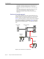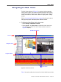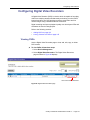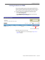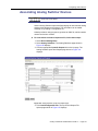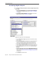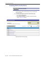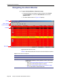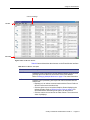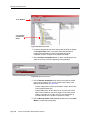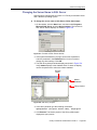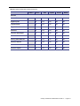
1
Facility Commander™
Administration Guide
Facility Commander
™
This publication may contain examples of screen captures and reports used in daily
operations. Examples include fictitious names of individuals and companies. Any similarity to
names and addresses of actual business enterprises and persons is entirely coincidental.
This document is distributed on an as is basis, without warranty either expressed or implied.
Successful implementation depends solely upon the customer’s ability to integrate each
product into the total inventory of “in-house” products. While each offering has been reviewed
for its transferability and maintainability, no assurance of successful installation can be given.
The customer accepts full maintenance responsibility. (A full scope of software and hardware
maintenance contracts are available to the customer.)
Copyright 2003-2005 GE Security
All Rights Reserved
Printed in the USA
Other product and company names herein may be the trademarks of their respective owners.
Acrobat is a registered trademark of Adobe Systems Incorporated.
ATI Hydravision is a registered trademark of ATI Technologies, Inc.
AutoCAD is a registered trademark of Autodesk Inc.
AIX is a registered trademark of International Business Machines (IBM).
Dell is a trademark of Dell Computer Corporation.
Informix is a registered trademark of IBM Corporation
Intel and Pentium are registered trademarks of Intel Corporation.
JLOOX is a trademark of eGenuity Technologies.
Lantronix is a registered trademark of Lantronix Corporation.
Linux Registered trademark of Linus Torvalds.
Microsoft, MS-DOS, Windows, and the Windows logo are registered trademarks of Microsoft
Corporation in the United States and other countries.
MySQL is a trademark of NuSphere Corporation.
Oracle is a registered trademark of Oracle Corporation.
Picture Perfect, Secure Perfect, and Facility Commander are registered trademarks of
GE-Security.
Red Hat is a registered trademark of Red Hat Incorporated.
Netscape is a registered trademark of Netscape Communications Corporation.
Shockwave is a registered trademark of Macromedia.
SQL Server is a registered trademark of Microsoft Corporation.
Travan is a registered trademark of Imation Corporation.
GE Infrastructure - Security
791 Park of Commerce Boulevard
Suite 100
Boca Raton, Florida 33487
(561) 998-6100
Part # 460571003A
February, 2005
Contents
About Document ......................................................................... 1
Who Should Use This Document ..........................................................1
How This Document Is Organized ........................................................1
Using This Document ...........................................................................3
Demonstrations .................................................................................3
Conventions Used In This Document ...................................................4
Related Documents ..............................................................................5
Chapter 1. Introduction .............................................................. 7
Overview ...............................................................................................8
Video Management ...............................................................................9
Centralized Video Management ........................................................9
Distributed Video Management .......................................................10
Minimum System Requirements .........................................................12
Remote Media Server .....................................................................13
Web Browser and Client Workstations ............................................14
Chapter 2. Getting Started ....................................................... 15
Overview .............................................................................................16
Starting and Shutting Down Facility Commander ............................16
Facility Commander Launcher ............................................................16
Minimizing Facility Commander Launcher .......................................18
Logging In from a Workstation ............................................................19
Logging In Using the Web Application ...........................................21
Using the Web Browser Application ...................................................21
List Page .........................................................................................22
Browser Menu .................................................................................25
Configuration Page ..........................................................................26
Managing Multiple Windows ...............................................................27
Client Application Title Bars ............................................................28
Customizing Window Name and Contents .........................................29
Error Messages ..................................................................................30
Navigating the Multi Viewer ................................................................31
Customizing the Multi Viewer ..........................................................32
Facility Commander Administration Guide 2.1
Page i
Chapter 3. Configuring the System ......................................... 33
Checklist .............................................................................................34
Facility Commander Servers ..............................................................37
Viewing Facility Commander Servers .............................................37
Adding a Facility Commander Server .............................................38
Access Control Systems .....................................................................44
Viewing Access Control Systems ....................................................44
Adding an Access Control System ..................................................45
Workstations .......................................................................................51
Configuring the Alarm Alert Window ...............................................51
Launching the Video Viewer Automatically .....................................51
Intercom Stations ............................................................................51
Viewing Defined Workstations .........................................................52
Adding a Workstation
..................................................................53
System Parameters ............................................................................56
Launch Video Viewer by Alarm Priority ...........................................56
Require an Alarm Response ...........................................................56
Configure Video Pre-Play Time .......................................................56
Configuring System Parameters .....................................................57
System Shutdown ............................................................................59
Shutdown Notification to Client Applications ...................................59
Shutdown Notification to Browser Configuration Clients .................59
Shutting Down the System ..............................................................59
Chapter 4. Importing Records ................................................. 61
Overview .............................................................................................62
Tag Names, Descriptions, and Record IDs .....................................62
Time Zones .....................................................................................62
Synchronize Records ......................................................................63
Terminology .....................................................................................63
Operator Records ...............................................................................65
Operator Passwords ........................................................................65
Operator Preferences ......................................................................65
Viewing Facility Commander Operators ..........................................66
Adding Operators ............................................................................67
Removing Default Account ..............................................................71
Importing Operators ........................................................................72
Changing Operator Preferences .....................................................73
Facilities ..............................................................................................74
Viewing Facilities .............................................................................75
Importing Facilities .........................................................................76
Creating a Facility ...........................................................................77
Members Tab
.............................................................................78
Parent Facility Tab .........................................................................79
Window Filter ......................................................................................80
Changing Contents of View .............................................................80
Access Points .....................................................................................81
Viewing Imported Access Points .....................................................81
Importing Access Points ..................................................................82
Editing Access Points ......................................................................83
Synchronizing Access Points ..........................................................86
Digital Inputs and Outputs ..................................................................87
Viewing Digital Inputs ......................................................................87
Importing Digital Inputs ...................................................................88
Editing Digital Inputs ........................................................................89
Synchronizing Digital Inputs ............................................................92
Page ii
Facility Commander Administration Guide 2.1
Viewing Logical Inputs .................................................................... 93
Importing Logical Inputs .................................................................. 94
Editing Logical Input Records ......................................................... 95
Synchronizing Logical Inputs .......................................................... 98
Viewing Digital Outputs ................................................................... 99
Importing Digital Outputs ............................................................. 100
Editing Digital Outputs .................................................................. 101
Synchronizing Digital Outputs ....................................................... 104
Chapter 5. Assigning Permissions and Context .................. 105
Overview .......................................................................................... 106
Facilities ........................................................................................ 106
Permissions .................................................................................. 106
Context ......................................................................................... 106
Pre-Defined Permissions and Context .......................................... 107
Examples ...................................................................................... 107
Checklist .......................................................................................... 107
Facility Permissions ......................................................................... 109
Using Pre-Defined Facility Permissions ........................................ 109
Viewing Facility Permissions ........................................................ 110
Adding Facility Permissions .......................................................... 111
System Permissions ........................................................................ 115
Using Pre-defined System Permissions ....................................... 115
Viewing System Permission ......................................................... 116
Adding System Permissions ......................................................... 117
Contexts ........................................................................................... 120
Viewing Context Definitions .......................................................... 120
Adding Context Definitions .......................................................... 121
Pre-defined Contexts ....................................................................... 124
Examples ......................................................................................... 125
Chapter 6. Configuring Video Devices ................................. 127
Overview .......................................................................................... 128
Video Devices .................................................................................. 128
Configuring Video IQ ........................................................................ 129
Configuring the DVMRe ................................................................ 129
Configuring Digital Video Recorders ................................................ 131
Viewing DVRs ............................................................................... 131
Adding DVRs ............................................................................... 132
Configuring Cameras ....................................................................... 138
Viewing Cameras .......................................................................... 138
Adding Cameras .......................................................................... 139
Configuring Camera Preset Positions .............................................. 143
Viewing Camera Preset Positions ................................................ 143
Adding Camera Preset Positions .................................................. 144
Linking Cameras to DVRs ................................................................ 145
Configuring Analog Switchers .......................................................... 147
Viewing Analog Switchers ............................................................ 147
Adding an Analog Switcher ........................................................... 148
Configuring CCTV Monitors ............................................................. 154
Viewing CCTV Monitors ................................................................ 154
Adding CCTV Monitors ................................................................. 155
Associating Analog Switcher Devices ............................................. 157
Troubleshooting Steps ..................................................................... 159
Facility Commander Administration Guide 2.1
Page iii
Chapter 7. Using the Video Viewer ....................................... 161
Overview ...........................................................................................162
Automatically Launch by Alarm Priority .........................................162
Multiple Camera Views ..................................................................163
Drag and Drop Cameras ...............................................................163
Navigating the Video Viewer ............................................................164
Controlling Cameras .........................................................................167
Live Video ......................................................................................167
Recorded Video .............................................................................167
Event Action Mapping ..................................................................167
Viewing Live Video ...........................................................................168
Adjust the Camera Lens ................................................................168
Viewing Recorded Video ..................................................................169
View a Single Video Frame ...........................................................169
Searching for Video ..........................................................................170
Search by Token ...........................................................................170
Search By Date and Time .............................................................172
Search by Play Position ................................................................173
Customizing the Video Viewer ..........................................................174
Add Customized Window Title ......................................................174
Managing Window Content ...........................................................175
Display Camera Identification ........................................................175
Display Additional Video Panes ....................................................176
Chapter 8. Event Action Mapping ......................................... 177
Overview ..........................................................................................178
Viewing Event Action Mappings .......................................................179
Tagging Video Events for Access Points ..........................................180
Tagging Video Events for Intercom Calls .........................................181
Activating Digital Outputs .................................................................182
Sending Automatic E-mails ..............................................................183
Events in Event Action Mapping .......................................................184
Actions in Event Action Mapping ......................................................188
Chapter 9. Configuring Alarms .............................................. 191
Overview ...........................................................................................192
Configuring the Alarm Monitor .......................................................193
Synchronization .............................................................................193
Setting Alarm Colors ........................................................................194
Creating Alarm Instructions .............................................................196
Creating Alarm Profiles ..................................................................198
Adding an Alarm Profile .................................................................199
Chapter 10. Using the Alarm Monitor ................................... 201
Overview ...........................................................................................202
Automatically Launch Video Viewer by Alarm Priority ...................202
Alarm Alert ........................................................................................203
Navigating the Alarm Monitor ...........................................................204
Customizing the Alarm Monitor ........................................................207
Changing Window Name and Contents ........................................207
Display Multiple Time Zones .........................................................208
Launch Video Automatically ..........................................................210
Responding to Alarms .....................................................................211
Alarm Response Required ............................................................211
Page iv
Facility Commander Administration Guide 2.1
Chapter 11. Using the Event Monitor ....................................215
Overview .......................................................................................... 216
Navigating the Event Monitor ........................................................... 216
Alarm Events List .......................................................................... 219
Badge Events List ......................................................................... 220
System Events List ....................................................................... 221
Setting Event Monitor Options ........................................................ 222
Changing the Event Types Filter ...................................................... 223
Event Types List ........................................................................... 224
Customizing Window Name and Contents ...................................... 226
Chapter 12. Configuring Intercom Devices .......................... 227
Overview .......................................................................................... 228
Terminology .................................................................................. 228
Checklist ....................................................................................... 228
Configuring Intercom Exchanges ..................................................... 229
Viewing Intercom Exchanges ....................................................... 229
Adding an Intercom Exchange ..................................................... 230
Configuring Intercom Stations .......................................................... 236
Viewing Intercom Stations ............................................................ 236
Adding Intercom Stations .............................................................. 237
Tips for Creating Symbol Schemes ................................................. 242
Intercom Exchange Symbol Scheme ............................................ 242
Intercom Master Station Symbol Scheme .................................... 243
Intercom Substation Symbol Scheme ........................................... 244
Chapter 13. Configuring Intrusion Devices .......................... 245
Overview .......................................................................................... 246
Terminology .................................................................................. 246
Configuring Intrusion Devices ....................................................... 247
Connecting Intrusion Panels ............................................................ 247
Ethernet Connection ..................................................................... 247
RS-232 Connection ...................................................................... 249
Configuring Intrusion Panels ............................................................ 250
Viewing Intrusion Panels .............................................................. 250
Adding Intrusion Panels ................................................................ 251
Configure Intrusion Areas ................................................................ 257
Viewing Intrusion Areas ................................................................ 257
Adding Intrusion Areas ................................................................. 258
Configuring DGPs ............................................................................ 262
Viewing Intrusion DGPs ................................................................ 262
Adding Intrusion DGPs ................................................................. 263
Configure Intrusion Input .................................................................. 266
Viewing Intrusion Input ................................................................. 266
Adding Intrusion Inputs ................................................................. 267
Configure Intrusion Outputs ............................................................. 271
Viewing Intrusion Outputs ............................................................. 271
Adding Intrusion Outputs .............................................................. 272
Configure Intrusion Keypads ............................................................ 275
Viewing Intrusion Keypads ........................................................... 275
Adding Intrusion Keypads ............................................................. 276
Facility Commander Administration Guide 2.1
Page v
Chapter 14. Creating Symbol Schemes ................................ 281
Overview ...........................................................................................282
Using the Symbol Editor ...................................................................283
Creating a Symbol Scheme .............................................................287
Creating an Intrusion Symbol Scheme .............................................288
Managing Symbol Editor Files ..........................................................290
Uploading a Symbol Scheme ........................................................290
Downloading a Symbol Scheme ...................................................290
Deleting a Symbol Scheme ...........................................................291
State Associations and Conditions ................................................291
Chapter 15. Creating Graphic Displays ................................ 297
Overview ...........................................................................................298
Using the Graphics Editor .................................................................299
Drawing Tools ...................................................................................303
Graphic Attributes .............................................................................304
Creating a Graphic Display ...............................................................306
Associating Access Points and Other Devices .............................307
Associating Camera Devices ........................................................308
Associating Intercom Devices .......................................................309
Creating Intrusion Areas ................................................................310
Adding Text Labels to the Site Map .............................................311
Saving the Site Map ......................................................................312
Importing AutoCAD Drawings ...........................................................312
Maintain Layers in AutoCAD Drawings .........................................315
Linking Graphic Displays ..................................................................316
Building Hierarchical Displays ..........................................................318
Working with Layers .........................................................................321
Creating a New Layer ...................................................................321
Selecting a Layer ...........................................................................322
Renaming a Layer .........................................................................323
Removing a Layer .........................................................................323
Moving Objects Between Layers ...................................................324
Managing Graphic Display Files .......................................................324
Uploading Graphic Displays ..........................................................324
Downloading Graphic Displays .....................................................326
Deleting Unused Files ...................................................................327
Editing Graphic Display Records ......................................................328
Chapter 16. Viewing Graphic Displays ................................. 331
Overview ...........................................................................................332
Alarm States ..................................................................................333
Navigating the Graphics Viewer .......................................................334
Opening Graphic Displays .............................................................336
Selecting Layers ............................................................................337
Issuing Commands ...........................................................................338
Lock and Unlock Doors .................................................................339
View Video from a Specific Camera ..............................................340
View Video from Monitor Devices .................................................341
Enable or Disable Input Devices ...................................................342
Connect and Disconnect Intercom Devices ..................................343
Arm or Disarm Intrusion Areas ......................................................344
Customizing Window Name and Contents .......................................345
Printing Graphic Displays .................................................................346
Page vi
Facility Commander Administration Guide 2.1
Chapter 17. Backup/Restore SQL Server 2000 Database .... 347
Overview .......................................................................................... 348
Backing Up Windows Files .............................................................. 349
Backing Up a SQL Server 2000 Database ...................................... 353
Restoring Files on Windows 2000 ................................................... 357
Restoring a SQL Server 2000 Database ......................................... 361
Chapter 18. Backup/Restore Informix and Oracle Databases ..
367
Overview .......................................................................................... 368
Backup Modes .............................................................................. 368
Backup Types ............................................................................... 369
Requirements (Tape Backups) ........................................................ 369
Tape Labels .................................................................................. 369
Backing Up Database Records ........................................................ 370
Informix Database ......................................................................... 371
Backing Up Files ........................................................................... 373
Restore Procedures ......................................................................... 375
Restore Incremental Backups ....................................................... 379
Restore Database ......................................................................... 380
Chapter 19. Viewing Diagnostics ........................................... 385
Overview .......................................................................................... 386
Changing Diagnostics Settings ........................................................ 387
Editing the Diagnostics Settings ................................................... 387
Resetting Diagnostics Statistics .................................................... 388
ATS Panel Intrusion ......................................................................... 389
Database Connection Pool .............................................................. 390
Database Transactions Diagnostics ................................................ 391
Database Queries Diagnostics ........................................................ 392
Facility Membership Cache .............................................................. 393
JVM Statistics .................................................................................. 394
Media Diagnostics ............................................................................ 395
Service Framework Diagnostics ...................................................... 396
System Status Diagnostics .............................................................. 397
Thread Pool Manager Diagnostics ................................................... 398
Chapter 20. Advanced Configuration ....................................399
Customizing Launcher Window ....................................................... 400
Adding Custom Icons .................................................................... 400
Adding External Applications ........................................................ 401
Verifying Computer Host Name ....................................................... 402
Changing the Host Name or IP Address .......................................... 403
Changing the Client Encryption .................................................... 405
Changing the Host Name on Server Record ................................ 405
Editing the System Configuration File on Server .......................... 406
Editing the SSL File on Server ...................................................... 407
Changing the Computer Name on Server .................................... 408
Changing the Server Name in SQL Server ................................... 409
Editing the Host File on a Client System ...................................... 410
Editing the Client Properties File on a Client System ................... 411
Editing the Picture Perfect Configuration File ............................... 411
Enabling SSL Encryption for Picture Perfect ................................... 412
Copying File from Facility Commander ......................................... 413
Moving File to Picture Perfect ....................................................... 414
Facility Commander Administration Guide 2.1
Page vii
Generating Picture Perfect Key File ..............................................414
Generating Picture Perfect Certificate Request ............................415
Generating Picture Perfect Signed Certificate ...............................416
Generating Picture Perfect PEM File ............................................416
Updating EIF Event Manager Configuration File ...........................416
Updating EIF Request Manager Configuration File .......................418
Copying Certificate to Facility Commander Server .......................420
Adding Picture Perfect Certificate .................................................421
Enabling SSL Communication on Facility Commander .................422
Enabling SSL Encryption for Secure Perfect ....................................423
Secure Perfect SSL Certificate Creation .......................................423
Multiple Secure Perfect SSL Connections ....................................424
Appendix A. Edit Configuration Files for Informix
Backup to Disk ........................................................................ 425
Configuration Files ...........................................................................426
Editing the Backup Utility Configuration File .....................................427
Editing the Informix Configuration File ..............................................428
Scheduling the Backup Utility ...........................................................429
Create a Cron Task .......................................................................429
Launch the Script Manually ...........................................................429
Appendix B. Troubleshooting Information ........................... 431
Appendix C. Error Messages ................................................. 435
Appendix D. Facility Permissions ......................................... 467
All Facility Permissions .....................................................................467
Entry Level Guard Facility Permissions ............................................470
Guard Supervisor Facility Permissions .............................................472
Intermediate Guard Facility Permissions ..........................................474
Update Configuration Facility Permissions .......................................476
View Configuration Facility Permissions ...........................................478
Appendix E. System Permissions ......................................... 481
All System Permissions ....................................................................481
Entry Level Guard System Permissions ...........................................483
Guard Supervisor System Permissions ............................................484
Intermediate Guard System Permissions .........................................485
Appendix E. Demos ................................................................ 487
Page viii
Facility Commander Administration Guide 2.1
List of Figures
Figure 1. Single server with centralized video .........................................9
Figure 2. Typical configuration with one Media Server. .........................10
Figure 3. Facility Commander Launcher window ...................................17
Figure 4. Facility Commander Launcher (minimized) elements .............18
Figure 5. Facility Commander Login Screen ..........................................19
Figure 6. Browser Interface — Login page ............................................21
Figure 7. Browser Interface — List Page ...............................................22
Figure 8. Browser menu .........................................................................25
Figure 9. Browser Interface — Configuration Page ...............................26
Figure 10. Title bars with window numbers, and other information ........28
Figure 11. Window Filter window ...........................................................29
Figure 12. Configuration pages with error messages ............................30
Figure 13. Multi Viewer window .............................................................31
Figure 14. Facility Commander Servers page .......................................37
Figure 15. Configure Facility Commander Server page .........................38
Figure 16. Configure Facility Commander Server — Address tab .........39
Figure 17. Configure Facility Commander Server — E-mail Server tab 40
Figure 18. Configure Facility Commander Server — Advanced tab ......41
Figure 19. Configure Facility Commander Server — Alarms tab ...........42
Figure 20. Configure Facility Commander Server — Facilities tab ........43
Figure 21. Access Control Systems page ..............................................44
Figure 22. Configure Access Control Systems page .............................45
Figure 23. Configure Access Control System — Address tab ...............46
Figure 24. Configure Access Control System — External System tab ..47
Figure 25. Configure Access Control System — Advanced tab ............48
Figure 26. Configure Access Control System — Alarms tab .................49
Figure 27. Configure Access Control — Facility Tab .............................50
Figure 28. Alarm Alert window ...............................................................51
Figure 29. Workstations page ................................................................52
Figure 30. Define Workstation page ......................................................53
Figure 31. Workstations — General tab .................................................54
Figure 32. Workstations — Facility tab ..................................................55
Figure 33. Configure System Parameters page .....................................57
Figure 34. Shutdown System page ........................................................59
Figure 35. Operators page .....................................................................66
Figure 36. Configure Operator page ......................................................67
Figure 37. Configure Operator — General tab .......................................68
Facility Commander Administration Guide 2.1
Page ix
Figure 38. Configure Operator — External System tab .........................69
Figure 39. Configure Operator — Facility tab ........................................70
Figure 40. Import page ..........................................................................72
Figure 41. Set Operator Preferences .....................................................73
Figure 42. Facilities page .......................................................................75
Figure 43. Import page ..........................................................................76
Figure 44. Configure Facility — Add New Facility .................................77
Figure 45. Configure Facility — Members tab .......................................78
Figure 46. Configure Facilities — Parent Facility tab .............................79
Figure 47. Window Filter page ...............................................................80
Figure 48. Access Points page ..............................................................81
Figure 49. Import page ..........................................................................82
Figure 50. Configure Access Point page ...............................................83
Figure 51. Configure Access Point — General tab ................................84
Figure 52. Configure Access Point — Facility tab .................................85
Figure 53. Synchronize page .................................................................86
Figure 54. Digital Inputs page ................................................................87
Figure 55. Import page ..........................................................................88
Figure 56. Configure Digital Input page .................................................89
Figure 57. Configure Digital Input — General tab ..................................90
Figure 58. Configure Digital Input — Facility tab ...................................91
Figure 59. Synchronize page .................................................................92
Figure 60. Logical Inputs page ..............................................................93
Figure 61. Import page ..........................................................................94
Figure 62. Configure Logical Input .........................................................95
Figure 63. Configure Logical Input — General tab ................................96
Figure 64. Configure Logical Input — Facility tab ..................................97
Figure 65. Synchronize page .................................................................98
Figure 66. Digital Output page ...............................................................99
Figure 67. Import page ........................................................................100
Figure 68. Configure Digital Output .....................................................101
Figure 69. Configure Digital Output — General tab .............................102
Figure 70. Configure Digital Output — Facility tab ..............................103
Figure 71. Synchronize page ...............................................................104
Figure 72. Context definition ................................................................106
Figure 73. Facility Permissions page ...................................................110
Figure 74. Configure Facility Permissions page ..................................111
Figure 75. Facility Permissions — Controls tab ...................................112
Figure 76. Facility Permissions — Monitors tab ..................................112
Figure 77. Facility Permissions — Setup tab .......................................113
Figure 78. Facility Permissions — Devices tab ...................................114
Figure 79. System Permissions ...........................................................116
Figure 80. Configure System Permissions page .................................117
Figure 81. Configure System Permissions page — Applications tab ..118
Figure 82. Configure System Permissions page — Editors tab ...........118
Figure 83. Configure System Permissions page — Operations tab ....119
Figure 84. Contexts page ....................................................................120
Figure 85. Define Context page ...........................................................121
Figure 86. Define Context — Permissions tab .....................................122
Figure 87. Define Context — Facility tab .............................................123
Figure 88. Two regional facilities and four imported facilities. .............125
Figure 89. Digital Video Recorders page .............................................131
Figure 90. Configure Digital Video Recorder page ..............................132
Figure 91. Configure DVR — Model tab ..............................................133
Page x
Facility Commander Administration Guide 2.1
Figure 92. Configure DVR — Addresses tab ...................................... 134
Figure 93. Configure DVR — Advanced tab ....................................... 135
Figure 94. Configure DVR — Alarms tab ............................................ 136
Figure 95. Configure DVR — Facility tab ............................................ 137
Figure 96. Cameras page ................................................................... 138
Figure 97. Configure Camera page ..................................................... 139
Figure 98. Configure Camera — General tab ..................................... 140
Figure 99. Configure Camera — Alarms tab ....................................... 141
Figure 100. Configure Camera — Facility tab ..................................... 142
Figure 101. Camera Presets page ...................................................... 143
Figure 102. Configure Camera Preset page ....................................... 144
Figure 103. Digital Video Recorders page .......................................... 145
Figure 104. Link Cameras page .......................................................... 146
Figure 105. Analog Switchers page .................................................... 147
Figure 106. Configure Analog Switcher page ..................................... 148
Figure 107. Configure Analog Switcher — Model tab ......................... 149
Figure 108. Configure Analog Switcher — Addresses tab .................. 150
Figure 109. Configure Analog Switcher — Advanced tab ................... 151
Figure 110. Configure Analog Switcher — Alarms tab ........................ 152
Figure 111. Configure Analog Switcher — Facility tab ........................ 153
Figure 112. CCTV Monitors page ....................................................... 154
Figure 113. Configure CCTV Monitor page ......................................... 155
Figure 114. Analog Switcher Inputs and Outputs page ....................... 157
Figure 115. Inputs and Outputs File Upload page .............................. 158
Figure 116. Illustration of multiple views in Video Viewer ................... 163
Figure 117. Video Viewer .................................................................... 164
Figure 118. Video Token Search window with Select Date window ... 170
Figure 119. Video Token Search window —Time Search tab ............ 172
Figure 120. Window Filter window ...................................................... 175
Figure 121. Event Action Mappings page ........................................... 179
Figure 122. Configure Event Action Mapping page ............................ 180
Figure 123. Configure Event Action Mapping page ............................ 181
Figure 124. Configure Event Action Mapping page ............................ 182
Figure 125. Configure Event Action Mapping page ............................ 183
Figure 126. Select Alarm Color Scheme page .................................... 194
Figure 127. Edit Alarm Color Scheme page ........................................ 195
Figure 128. Alarm Instructions page ................................................... 196
Figure 129. Configure Alarm Instruction page .................................... 197
Figure 130. Alarm Profiles ................................................................... 198
Figure 131. Define Alarm Profile ......................................................... 199
Figure 132. Alarm Alert window .......................................................... 203
Figure 133. Alarm Monitor window ...................................................... 204
Figure 134. Window Filter window ...................................................... 207
Figure 135. Alarm Monitor Options window — Columns tab .............. 208
Figure 136. Alarm Monitor Options window — Setup tab ................... 210
Figure 137. Alarm Response window ................................................. 212
Figure 138. Event Monitor window ...................................................... 217
Figure 139. Event Monitor Options window ........................................ 222
Figure 140. Event Type Filter .............................................................. 223
Figure 141. Window Filter window ...................................................... 226
Figure 142. Intercom Exchanges page ............................................... 229
Figure 143. Configure Intercom Exchanges page ............................... 230
Figure 144. Configure Intercom Exchanges — Model tab .................. 231
Figure 145. Configure Intercom Exchanges — Addresses tab ........... 232
Facility Commander Administration Guide 2.1
Page xi
Figure 146. Configure Intercom Exchanges — Advanced tab .............233
Figure 147. Configure Intercom Exchanges — Alarms tab .................234
Figure 148. Configure Intercom Exchanges — Facility tab .................235
Figure 149. Intercom Stations list page ...............................................236
Figure 150. Configure Intercom Station page ......................................237
Figure 151. Configure Intercom Station — General tab ......................238
Figure 152. Configure Intercom Station — Monitoring tab ..................239
Figure 153. Configure Intercom Station — Alarms tab ........................240
Figure 154. Configure Intercom Stations — Facility tab ......................241
Figure 155. Example Intercom Exchange Symbol Scheme ................242
Figure 156. Example Intercom Master Station Symbol Scheme .........243
Figure 157. Example Intercom Substation Symbol Scheme ...............244
Figure 158. Intrusion Panels page .......................................................250
Figure 159. Intrusion Panel page .........................................................251
Figure 160. Intrusion Panel — Model tab ............................................252
Figure 161. Intrusion Panel — Addresses tab .....................................253
Figure 162. Intrusion Panel — Advanced tab ......................................254
Figure 163. Intrusion Panel — Alarms tab ...........................................255
Figure 164. Intrusion Panel — Facility tab ...........................................256
Figure 165. Intrusion Areas page ........................................................257
Figure 166. Configure Intrusion Area page ..........................................258
Figure 167. Configure Intrusion Area — General tab ..........................259
Figure 168. Configure Intrusion Area — Alarms tab ............................260
Figure 169. Configure Intrusion Area — Facility tab ............................261
Figure 170. Intrusion DGPs page ........................................................262
Figure 171. Configure Intrusion DGP page .........................................263
Figure 172. Configure Intrusion DGP — Alarms tab ............................264
Figure 173. Configure Intrusion DGP — Facility tab ............................265
Figure 174. Intrusion Inputs page ........................................................266
Figure 175. Configure Intrusion Inputs page .......................................267
Figure 176. Configure Intrusion Inputs — General tab ........................268
Figure 177. Configure Intrusion Inputs — Alarms tab ..........................269
Figure 178. Configure Intrusion Inputs — Facility tab ..........................270
Figure 179. Intrusion Outputs page .....................................................271
Figure 180. Configure Intrusion Outputs page .....................................272
Figure 181. Configure Intrusion Outputs — General tab .....................273
Figure 182. Configure Intrusion Output — Facility tab .........................274
Figure 183. Intrusion Keypad page ......................................................275
Figure 184. Configure Intrusion Outputs page .....................................276
Figure 185. Configure Intrusion Keypad — General tab ......................277
Figure 186. Configure Intrusion Keypad — Alarms tab .......................278
Figure 187. Configure Intrusion Output — Facility tab .........................279
Figure 174. Symbol Editor window ......................................................284
Figure 175. Attach window with available symbols ..............................287
Figure 176. Attributes Panel window ...................................................288
Figure 177. Input window .....................................................................291
Figure 177. Graphics Editor window ....................................................300
Figure 178. Graphic Attributes window ................................................305
Figure 179. Device Palette window .....................................................306
Figure 180. Set Association button ......................................................307
Figure 181. Set Association window ....................................................307
Figure 182. Set Association window ....................................................308
Figure 183. Set Association window ....................................................309
Figure 184. Graphic Editor with defined intrusion area ........................310
Page xii
Facility Commander Administration Guide 2.1
Figure 185. Adding text to drawing in Graphics Editor window ........... 311
Figure 186. Import AutoCAD Drawings window .................................. 312
Figure 187. Drawing limits window ...................................................... 313
Figure 188. Select Layers to Import window ....................................... 314
Figure 189. Import DXF menu options ................................................ 315
Figure 190. Layer Settings with imported and non-imported layers .... 315
Figure 191. Hyperlink icon and associated graphic display ................ 316
Figure 192. Change Linking Properties button .................................... 316
Figure 193. Hyperlink Settings window ............................................... 317
Figure 194. Hierarchal map arrangement ........................................... 318
Figure 195. Hyperlink Path Settings window ....................................... 320
Figure 196. Create New Layer window ............................................... 321
Figure 197. Layer settings window ...................................................... 322
Figure 198. Rename Layer window .................................................... 323
Figure 199. Select layer window ......................................................... 323
Figure 200. Select Layer window ........................................................ 324
Figure 201. Upload window ................................................................. 325
Figure 202. Download window ............................................................ 326
Figure 203. Deleting Graphics Files window ....................................... 327
Figure 204. Graphic Displays page ..................................................... 328
Figure 205. Configure Graphic Display page ...................................... 329
Figure 205. Graphics Viewer window .................................................. 334
Figure 206. Download window ............................................................ 336
Figure 207. Show/Hide Layer window ................................................ 337
Figure 208. Site map with action menu ............................................... 339
Figure 209. Lock and unlock door options .......................................... 340
Figure 210. Graphic display with video devices .................................. 340
Figure 211. Graphical display with monitors ....................................... 341
Figure 212. Monitor window ................................................................ 342
Figure 213. Graphic display with an intercom device .......................... 343
Figure 214. Graphic display with an intercom device .......................... 344
Figure 215. Window Filter ................................................................... 345
Figure 216. Print View window ............................................................ 346
Figure 217. Windows 2000 Backup and Recovery Tools window ...... 349
Figure 218. Backup window ................................................................ 350
Figure 219. Backup destination ........................................................... 350
Figure 220. Backup Job Information window ...................................... 351
Figure 221. Advanced Backup Options window .................................. 352
Figure 222. SQL Server Enterprise Manager window ......................... 353
Figure 223. SQL Server Backup window ............................................ 353
Figure 224. Select Backup Destination window .................................. 354
Figure 225. SQL Server Backup window ............................................ 355
Figure 226. SQL Server Backup window ............................................ 356
Figure 227. SQL Server Enterprise Manager window ......................... 356
Figure 228. Backup window ................................................................ 357
Figure 229. New Import Media window ............................................... 358
Figure 230. Backup [Restore] window ................................................ 358
Figure 231. Options (Backup - Restore) window ................................ 359
Figure 232. Backup [Restore] window - bottom pane ......................... 359
Figure 233. Confirm Restore window .................................................. 359
Figure 234. Restore Progress window ................................................ 360
Figure 235. SQL Server Enterprise Manager window ......................... 361
Figure 236. Restore database window ................................................ 362
Figure 237. Choose Restore Devices window .................................... 362
Facility Commander Administration Guide 2.1
Page xiii
Figure 238. Choose Restore Destination window ................................363
Figure 239. Choose Restore Devices window .....................................363
Figure 240. Restore database window ................................................364
Figure 241. Choose Restore Devices window .....................................364
Figure 242. Restore Progress ..............................................................365
Figure 243. Restore Progress window .................................................365
Figure 244. Backup Utility ....................................................................370
Figure 245. Starting a full-level database backup ................................371
Figure 246. Database backup complete ..............................................372
Figure 247. Backup verification ...........................................................372
Figure 248. Start backup of files ..........................................................373
Figure 249. Waiting to start file backup verification .............................374
Figure 250. Successful file backup verification ....................................375
Figure 251. Backup Utility ....................................................................376
Figure 252. Start Restore process with tape in drive ...........................377
Figure 253. File restoration complete ..................................................378
Figure 254. Restore incremental backups ...........................................379
Figure 255. Wait for database tape to be loaded .................................380
Figure 256. Restore details ..................................................................380
Figure 257. Prompt for salvaging logs .................................................381
Figure 258. Logical logs restored ........................................................381
Figure 259. Restore log tapes .............................................................382
Figure 260. Reboot system to start database ......................................383
Figure 261. Diagnostics page ..............................................................387
Figure 262. Diagnostics Edit page .......................................................388
Figure 263. Component Diagnostics page ..........................................389
Figure 264. Database Connection Pool page ......................................390
Figure 265. Database Transactions .....................................................391
Figure 266. Database Queries page ....................................................392
Figure 267. Facility Membership Cache page .....................................393
Figure 268. JVM Diagnostics page ......................................................394
Figure 269. Media Diagnostics page ...................................................395
Figure 270. Service Framework Diagnostics page ..............................396
Figure 271. System Status Diagnostics page ......................................397
Figure 272. Thread Pool Diagnostics ..................................................398
Figure 273. Notepad application added to Launcher window ..............401
Figure 274. Sample System Configuration file ....................................406
Figure 275. Sample SSL file ................................................................407
Figure 276. Identification Changes window .........................................408
Figure 277. Connect to SQL Server window .......................................409
Figure 278. SQL Query Analyzer .........................................................409
Figure 279. SQL Server Service Manager window ..............................410
Page xiv
Facility Commander Administration Guide 2.1
About Document
This document describes Facility Commander and its components. It also
includes instructions to configure the system and use the client
applications.
Who Should Use This Document
This document is intended for system administrators who are responsible
for planning, configuring, and operating Facility Commander.
Administrators should be familiar with personal computers, client and
server relationships, databases, Web browsers, and graphical user
interface (GUI) navigation. They must also have a working knowledge of
the following:
•
Picture Perfect application
•
Secure Perfect application
•
Digital Video (CCTV) equipment
•
Intercom equipment
•
Intrusion equipment
•
Database operations
•
Security needs of the customer’s facility
Operators using the system should read the chapters relating to their
duties and responsibilities.
How This Document Is Organized
This document is organized as follows:
•
Chapter 1. Introduction on page 7 describes the system
components, and describes how remote media servers are used
to transmit video.
•
Chapter 2. Getting Started on page 15 describes the Facility
Commander Launcher, instructions on how to log in to the system
using the client application, and the Web interface.
Facility Commander Administration Guide 2.1
Page 1
How This Document Is Organized
Page 2
•
Chapter 3. Configuring the System on page 33 describes setting
up the system by identifying the Facility Commander server,
Picture Perfect server, Secure Perfect, system parameters, and
more.
•
Chapter 4. Importing Records on page 61 describes how to import
Picture Perfect and Secure Perfect operators, facilities, doors, and
other records to Facility Commander.
•
Chapter 5. Assigning Permissions and Context on page 105
describes how to assign operator permissions.
•
Chapter 6. Configuring Video Devices on page 127 describes how
to configure DVRs, cameras, and camera preset positions, as well
as CCTV Monitors and Analog Switchers.
•
Chapter 7. Using the Video Viewer on page 161 describes how to
view live and recorded video; and how to search for video clips.
•
Chapter 8. Event Action Mapping on page 177 describes how to
associate events to actions. When an alarm occurs, video events
can be tagged for later investigation, to send e-mails, and more.
•
Chapter 9. Configuring Alarms on page 191 describes how to
change alarm colors, create alarm instructions, and alarm profiles.
•
Chapter 10. Using the Alarm Monitor on page 201 describes using
the Alarm Monitor window, how to select time zones, and view
maps and video of alarm events.
•
Chapter 11. Using the Event Monitor on page 215 describes the
Event Monitor window and how to filter events.
•
Chapter 12. Configuring Intercom Devices on page 227 describes
how to configure intercom devices.
•
Chapter 13. Configuring Intrusion Devices on page 245 describes
how to configure intrusion devices and instructions to use when
connecting the intrusion equipment to Facility Commander.
•
Chapter 14. Creating Symbol Schemes on page 281 describes
how to create a symbol scheme to use with graphic displays. Also
included are instructions to upload and download files.
•
Chapter 15. Creating Graphic Displays on page 297 describes
how to use the Symbol Editor and Graphic Editor to associate
icons representing devices with graphical displays, or site maps.
•
Chapter 16. Viewing Graphic Displays on page 331 describes how
to use the Graphics Viewer, display different layers, and issue
commands such as locking and unlocking doors.
•
Chapter 19. Viewing Diagnostics on page 385 describes the
information needed to monitor the system.
•
Appendix C.on page 435 lists Facility Commander error messages
and suggestions to resolve the errors.
•
Appendix B.on page 431 lists miscellaneous problems and
describes the causes and appropriate actions.
•
Appendix E.on page 487 lists the animations that are included with
this document. Refer to Demonstrations on page 3 for more
information.
Facility Commander Administration Guide 2.1
Using This Document
This document is available in portable document format (PDF). The PDF
document has been designed for online, interactive viewing with Adobe®
Acrobat® Reader Version 4.0 or later.
The Acrobat Reader is available for the Windows®, Macintosh®, Unix®,
Linux®, and IBM® AIX®. The Acrobat Reader can be obtained for free
from Adobe Systems Incorporated (http://www.adobe.com).
The table of contents, bookmarks, cross-references, index entries, and
thumbnail pages are active navigation elements. Cross-references and
links are displayed in blue. Select these elements to quickly move through
the document. Any page in the document or the entire document can be
printed while viewing it in the Acrobat Reader.
Demonstrations
This document has been designed with hyperlinks to animations that
demonstrate how to complete a particular task. When you see this film
strip, double-click to launch the demo.
Click icon to see demo.
To take advantage of this feature, make sure the demo files reside in the
same directory as the Facility Commander Administration Guide PDF file.
Refer to Appendix E.on page 487 for a complete list of demos in the
Administration Guide.
The animations are designed to display with Internet Explorer 6.0 or later.
Facility Commander Administration Guide 2.1
Page 3
Conventions Used In This Document
Conventions Used In This Document
The following conventions are used in this document:
Bold type
• Text to be entered by the reader.
• Menu items, buttons, programs, and other GUI elements
selected with a mouse or keyboard by the reader.
Italic type
• Titles of books and various documents.
• Cross-references to headings within a document.
• E-mail and Web site (or URL) addresses.
• Emphasis of an instruction or point.
• Variables.
Page 4
Monospace
type
• Text that displays on the computer screen
Blue, blue, or
blue type
• In online versions of this document, hyperlinked elements
that take the reader directly to the cross-references, related
topics, and URL addresses.
• Examples of path names or coding sequences
Facility Commander Administration Guide 2.1
Related Documents
The following documents contain information about the Picture Perfect
application:
•
Picture Perfect AIX® Installation Guide
This document describes how to install and configure the Picture
Perfect application and the AIX operating system; and connect
hardware, such as modems, printers, and micro controllers.
•
Picture Perfect Linux® Installation Guide
This document describes how to install and configure the Picture
Perfect application and the Linux/AIX operating systems; and
connect hardware, such as modems, printers, and
microcontrollers.
•
Picture Perfect Administration Guide
This document describes how to configure, and manage the
Picture Perfect application. It describes the Picture Perfect
interface and contains step-by-step procedures to use the
application.
•
Picture Perfect Enterprise Administration Guide
This document describes how to configure, and manage the
Picture Perfect Enterprise application. It describes the Picture
Perfect interface and contains step-by-step procedures to use the
application.
•
Picture Perfect Redundant Administration Guide
This document describes how to configure, and manage the
Picture Perfect Redundant (PPRS) application. It describes the
Picture Perfect interface and contains step-by-step procedures to
use the application.
The following documents contain information about the Secure Perfect
application:
•
Secure Perfect Installation Guide
This document provides information for system administrators to
set up, install, and configure the Secure Perfect 5.0 application.
•
Secure Perfect Online Help System
The online help system includes reference information about
menus, windows, and field descriptions. Instructions for system
administrators, such as configuring microcontrollers, are included
and more.
•
Secure Perfect Database Triggers
This document contains instructions to import and link external
databases, such as human resources databases, to Secure
Perfect. Imported data is inserted into the Secure Perfect database
to make the task of configuring operator records easier.
•
Secure Perfect and Microsoft Access 2002
This document is used only for writing custom reports using
Access 2002 database projects and Secure Perfect databases.
Facility Commander Administration Guide 2.1
Page 5
Related Documents
Page 6
Facility Commander Administration Guide 2.1
Chapter 1. Introduction
This chapter describes Facility Commander and its features, including
integrated video and video management. Readers should familiarize
themselves with this chapter before proceeding to other chapters in this
document.
In this chapter:
Overview on page 8
Video Management on page 9
Minimum System Requirements on page 12
Facility Commander Administration Guide 2.1
Page 7
Overview
Overview
Facility Commander is a security integration platform that provides
integrated digital video, analog video switchers, intercom, and intrusion
with access control. It interfaces with Picture Perfect and Secure Perfect,
which continue to perform all access control, alarm, and reporting tasks.
The main features of Facility Commander include a comprehensive alarm
management system with direct access to graphical maps and video clips
from the Alarm Monitor, and a high-level command and control interface
to Digital Video Recorders (DVRs) and their connected cameras.
Configuring Facility Commander is accomplished using a Web browser,
such as Internet Explorer. Operators select which facilities, doors, inputs,
and outputs they want to control from Facility Commander and import
these records from the access control system.
The alarm events associated with these devices can be configured to
perform any number of actions in Facility Commander. For example, if a
door has a video camera monitoring it, whenever a Door Forced alarm
occurs, the system can be configured to send an e-mail notice to the
Security Supervisor, and also tag the video clip so it can be reviewed
later.
Monitoring the system is accomplished using the Facility Commander
Launcher, which provides the capability to monitor alarms and control
video cameras. All alarms generated by Picture Perfect or Secure Perfect
are sent to the access control system’s Alarm Monitor, and also to the
Facility Commander Alarm Monitor. From the Facility Commander Alarm
Monitor, security personnel can perform all of the operations that they can
do on Picture Perfect or Secure Perfect, and more.
The Facility Commander Command and Control client features include:
Page 8
•
Create or import site maps for graphical representation of device
and alarm locations
•
Associate symbols and icons with devices, such as doors,
intercoms, intrusion devices, and cameras
•
Display a graphical map showing the location of an alarm and the
alarm state
•
Control devices from graphical maps, such as locking or unlocking
a door
•
Acknowledge alarms from either the graphical map or from the
alarm monitor
•
View recorded video clips associated with alarm events
•
View live video from fixed or PTZ cameras
•
Control a PTZ camera on-screen by using the mouse to pan, tilt,
and zoom
•
Search for video clips stored on a DVR by event, event type,
camera, or DVR
Facility Commander Administration Guide 2.1
Introduction
Video Management
The key feature of Facility Commander is integrated digital video. There are
two architectural configurations available, depending on the organization’s
size and geographic locations.
If the site is relatively small or in one central location, then the Facility
Commander server can manage the video services.
In large environments with several geographically distributed sites, it may
be undesirable to transmit video clips across the network. In this case,
adding a Remote Media Server to the system improves the video
transmission process.
Centralized Video Management
Using a single server configuration, this example describes the events that
occur when an operator wants to see video. The Facility Commander server
in Figure 1 has two DVRs with four cameras and two client workstations.
Access Control
Server
Facility Commander
Server
Facility Commander
Clients
DVR 1
Cam 1 Cam 2
DVR 2
Cam 3
Cam 4
Figure 1. Single server with centralized video
The illustration includes the following process:
•
The client workstation sends a message to Facility Commander
server requesting a connection to camera two.
•
The Facility Commander server performs a lookup in the database
to identify which DVR the camera is connected to, and which server
system manages the DVR. In this example, there is only one server
configured in the network.
Facility Commander Administration Guide 2.1 Page 9
Video Management
•
The Facility Commander sends a reply to the client with the server
identification. The client workstation opens a TCP/IP socket
connection to the Facility Commander server to receive the video
stream.
•
The Facility Commander server sends video from the associated
DVR to the client workstations. Using the Video Viewer
application, the operator is able to view the video stream from
camera two.
Distributed Video Management
Using a Facility Commander server with a Remote Media Server, this
example describes the events when an operator from a remote location
wants to see video. The Facility Commander system has two sites in
Figure 2, each with two DVRs, four cameras, and two client workstations.
In this example, the Media Server transmits the video from the camera
device to the client application. The illustration in Figure 2 shows two
systems that can be located anywhere — in the same city or different
cities.
Access Control
Server
Facility Commander
Server
Clients
Site One
DVR 1
Remote Media Server
Cam 1 Cam 2
Site Two
DVR 2
Cam 3
Figure 2. Typical configuration with one Media Server.
Page 10
Facility Commander Administration Guide 2.1
Cam 4
Introduction
The example describes the events when an operator using the Video
Viewer on the client system requests video from camera five at preset
position number two. This camera device is located at site two, which is
managed by the Media Server as shown in Figure 2 on page 10.
•
The client system sends a message to Facility Commander server
requesting a connection to camera five and preset position two.
•
The Facility Commander server performs a lookup in the database
to identify which DVR the camera is connected to, and which
system controls the manages the components.
•
The Facility Commander sends a message to the Media Server to
expect a connection from the client system. The client system
opens a TCP/IP connection socket to the Media Server with the
server configuration to receive the video stream.
•
The remote Media Server sends compressed video from the
associated DVR to the client workstations. Using the Video Viewer
application, the operator is able to view the video stream from
camera five at the preset position two.
The Media Server guarantees that local video does not have to be
processed by a Facility Commander server located remotely, but by the
Remote Media Server that is closer to the client workstations.
Facility Commander Administration Guide 2.1 Page 11
Minimum System Requirements
Minimum System Requirements
Refer to the tables which follow which list system requirements for:
•
•
Facility Commander Server
Remote Media Server
Using GE Security-supplied computers is strongly recommended, as they
have undergone significant reliability testing. If you decide to use non-GE
Security supplied computers and require technical support, service is
chargeable at normal Customer Support rates. Additionally, compatibility
with future product releases cannot be guaranteed.
Table 1. System Requirements: Facility Commander Server
Facility Commander Server
Function
Facility Commander and its database run on the Server.
Windows 2000 Server
(Service Pack 4)
Operating
System
• Red Hat Linux 7.3
(Informix)
• Red Hat AS 2.1(Oracle)
• FC 2.0:
AIX 5L (5.1) ML 04
• FC 2.1:
AIX 5L (5.1) ML 06
Hardware
• Dell™ Power-Edge
2600, 1.8 GHz
• 512 MB RAM;
recommend
1 GB
• 36 GB hard drive
• 24x CD-ROM drive
• 20-40 GB 4mm tape
drive
• Intel® 10/100 Mbps
NIC
• 56K modem
• mouse
• Dell Power-Edge 2600,
1.8 GHz
• 512 MB RAM;
recommend
1 GB
• 36 GB hard drive capacity
• 24x CD-ROM drive
• 20-40 GB 4mm tape drive
• Intel 10/100 Mbps NIC
• 56K modem
• mouse
• RISC System/6000
166 MHz (Model
7025-F40)
• 512 MB RAM;
recommend
1 GB
• SCSI Controller
• 18 GB hard drive*
• 24x CD-ROM drive
• 20-40 GB 4mm tape
drive
• Intel 10/100 Mbps NIC
• 56K modem
• mouse
RAID
Options
• RAID1
RAID5
RAID10
• RAID1
RAID5
RAID10
• RAID 1
RAID 5
RAID10
Databases
Supported
• SQL Server® 2000
Service Pack 3
(Standard Edition or
Enterprise Edition)
• MSDE on Windows
2000 Professional
• Informix® Dynamic Server
2000 version 9.4
• Oracle 9i version 9.2.0.1
• Informix® Dynamic
Server 2000 version
9.4
• Oracle 9i version
9.2.0.3
Page 12
Facility Commander Administration Guide 2.1
Introduction
Facility Commander Server
Notes
Visit the web site:
http://www.redhat.com/
hardware
to get a complete list of
computers and hardware
supported by Red Hat.
* Recommend four 18 GB
drives for Oracle. (Drive 1
contains the operating
system, drives 2 and 3
contain the database, and
drive 4 for archiving.)
Remote Media Server
Table 2 lists the system requirements for the Remote Media Server.
Table 2. System Requirements: Remote Media Server
Remote Media Server
Function
The Remote Media Server is an optional component for environments with
geographically distributed sites, where it may be undesirable to transmit video
clips across the network. It runs the media software and does not have a user
interface and does not contain a database. The Remote Media Server
connects to remote Digital Video Recorders and processes the requests for
video tagging and video playback (that the Facility Commander Server would
normally process in a smaller environment).
Some digital video vendors’ software interfaces are Windows DLL-dependent.
In those cases, the Media Server must be a Windows PC
Operating System
Hardware
Windows 2000
Professional
• Dell OptiPlexGX260D
1.8 GHz
• 512 MB memory
• 20 GB hard drive
• 48x CD-ROM
• Intel 10/100 Mbps NIC
• Alternative: Dell
PowerEdge 2600
Red Hat Linux 7.3
• Dell OptiPlexGX260D
1.8 GHz
• 512 MB memory
• 20 GB hard drive
• 48x CD-ROM
• Intel 10/100 Mbps NIC
• Alternative: Dell
PowerEdge 2600
Facility Commander Administration Guide 2.1 Page 13
Minimum System Requirements
Web Browser and Client Workstations
Table 3 lists the system requirements for the Web browser or client
workstations.
Table 3. System Requirements: Web Browser or Client Workstation
Web Browser or Client Workstation
Operating System
Windows 2000 Professional
Web Browser
Internet Explorer 6.0 with Service Pack 1 or later
Hardware
Page 14
•
•
•
•
•
Facility Commander Administration Guide 2.1
Dell OptiPlexGX260D 1.8GHz
256 MB memory (512 recommended)
20 GB hard drive
48x CD-ROM
Intel 10/100 Mbps NIC
Chapter 2. Getting Started
This chapter describes how to log in and use the Facility Commander
Launcher to open other applications; and how to use the Web browser to
configure the system. Also included are instructions on how to navigate
the browser interface and a description of the common elements,
including error messages.
Readers should familiarize themselves with this chapter before
proceeding to other chapters in this document.
In this chapter:
Overview on page 16
Facility Commander Launcher on page 16
Logging In from a Workstation on page 19
Logging In Using the Web Application on page 21
Using the Web Browser Application on page 21
Managing Multiple Windows on page 27
Customizing Window Name and Contents on page 29
Error Messages on page 30
Navigating the Multi Viewer on page 31
Facility Commander Administration Guide 2.1
Page 15
Overview
Overview
This chapter introduces you to the Facility Commander interface and
describes how to log in and access the Web browser interface and other
client applications.
Starting and Shutting Down Facility Commander
Facility Commander is started automatically as a service in the Windows
and Linux/AIX operating systems. Use this URL to access the Web pages
to configure Facility Commander:
http://hostname:8085/Merlin/index.htm
Refer to System Shutdown on page 59 for instructions to shut down the
system.
Facility Commander Launcher
When the client application is started from a workstation, it displays the
Facility Commander Launcher window which allows you to launch other
client applications, display Web pages to configure network parameters
for client-to-server communications, and log out.
Using the Facility Commander Launcher shown in Figure 3 on page 17,
you can open the Web browser and other client applications, such as:
• Alarm Monitor
• Video Viewer
• Graphics Editor
• Event Monitor
• Graphics Viewer
• Symbol Editor
• Multi Viewer
The Facility Commander Launcher window can be minimized to display
as a toolbar as shown in Figure 4 on page 18. The Launcher can also be
customized — you can replace the icons and you can add up-to-six
additional icons to launch other applications, such as WaveReader. Refer
to Customizing Launcher Window on page 400.
The items appearing on the Facility Commander Launcher window
depend on the Facility Commander user’s context and permissions. The
system administrator may be able to view all the items while another
operator may only be able to view the Alarm Monitor. Refer to Assigning
Permissions and Context on page 105 for more information.
Page 16
Facility Commander Administration Guide 2.1
Getting Started
Title Bar
Menu Bar
Login/Logoff Button
Toolbar Icons
Server Connection Icon
Figure 3. Facility Commander Launcher window
Table 4 lists and describes the elements of the Facility Commander
Launcher.
Table 4. Facility Commander Launcher elements
Element
Description
Title Bar
Displays the user’s name, the Facility Commander server
name, and the user’s context information.
Menu Bar
Displays a menu bar that allows you to launch the client
applications, access the Facility Commander Web browser,
open the Online Help system, and exit.
Login/Logoff Button
Click this button to log in to or exit from Facility Commander.
Toolbar Icons
Select the appropriate icon from the toolbar to open a client
application or Web browser interface.
Use to launch the Multi Viewer application.
Use to launch the Alarm Monitor application.
Use to launch the Event Monitor application.
Use to launch the Video Viewer application.
Use to launch the Graphic Viewer application.
Facility Commander Administration Guide 2.1
Page 17
Facility Commander Launcher
Table 4. Facility Commander Launcher elements
Element
Description
Use to launch the Graphic Editor application.
Use to launch the Symbol Editor application.
Use to launch the Facility Commander Web browser
application.
Server Connection
Icon
Indicates if the system with the client application is connected
to the Facility Commander server.
• Green indicates the client application is communicating
with the server.
• Red indicates the client application is no longer
communicating with the server.
Minimizing Facility Commander Launcher
!
To minimize the Facility Commander Launcher window, follow these
steps:
1. Select View.
2. Select Toolbar. The minimized Facility Commander toolbar
displays as shown in Figure 5.
Title Bar
Menu Bar
Toolbar Icons
Server Connection Icon
Figure 4. Facility Commander Launcher (minimized) elements
Table 5 on page 19 lists and describes the elements of the Facility
Commander Launcher.
Page 18
Facility Commander Administration Guide 2.1
Getting Started
Table 5. Facility Commander Launcher elements (Minimized)
Element
Description
Title Bar
Displays the user’s name, the Facility Commander server
name, and the user’s context information.
Menu Bar
Displays a menu bar that allows you to launch the client
applications, access the Facility Commander Web browser,
open the Online Help system, and exit.
Toolbar Icons
Select the appropriate icon from the toolbar to open a client
application or Web browser interface. Refer to Toolbar Icons
on page 17 for a description of each icon.
Server Connection
Icon
Indicates if the system with the client application is connected
to the Facility Commander server.
• Green indicates the client application is communicating
with the server.
• Red indicates the client application is no longer
communicating with the server.
Logging In from a Workstation
!
To display the Facility Commander Launcher window, follow these
steps:
1. Click Start, Programs, and then Facility Commander Client.
2. Select Facility Commander Client. The Facility Commander
Login window in Figure 5 displays.
Figure 5. Facility Commander Login Screen
3. Enter a user name and password and click Log In. For more
information about the Login window fields, refer to Table 6 on page
20.
Facility Commander Administration Guide 2.1
Page 19
Logging In from a Workstation
Table 6. Login window fields
Page 20
Field Name
REQ
Description
User Name
"
Enter a valid user’s name. The first time you log in you must
log in with the name indicated by the System Administrator.
Before you log in, an operator account must be created.
Password
"
Enter a valid password. If you do not enter a password, an
error message is displayed.
Facility Commander Administration Guide 2.1
Getting Started
Logging In Using the Web Application
Click icon to see demo.
The Facility Commander uses a Web browser application to configure
network parameters for client-to-server communications and media
devices such as cameras and DVRs, add new or import existing
operators from a Picture Perfect system, and more.
Type your user name and
password. Click Submit.
Figure 6. Browser Interface — Login page
Table 6 on page 20 lists and describes the login fields. Refer to Using the
Web Browser Application on page 21 for more information about using
the Web interface to configure Facility Commander.
Using the Web Browser Application
The Facility Commander Web browser interface displays two types of
pages — a list page and a configuration page. Refer to the following
sections for a description of each:
•
List Page
•
Configuration Page on page 26
•
Client Application Title Bars on page 28
•
Customizing the Multi Viewer on page 32
Common elements on both pages include: page name, system
messages, navigation pane, context, page displays options, and online
help.
Facility Commander Administration Guide 2.1
Page 21
Using the Web Browser Application
List Page
When you select any item from the Browser Menu, the list page displays.
The list page in Figure 7 shows all the defined records and is sorted in
alphabetical order. The list page allows you to view, copy, or delete
records.
Online Help
Information Bar
Messages
Page Display
Options
Page Name
Browser Menu
Search
Icons
Links
Figure 7. Browser Interface — List Page
Table 7 on page 23 lists and describes the elements of the List Web page.
Page 22
Facility Commander Administration Guide 2.1
Getting Started
Table 7. Web interface elements and descriptions
Element
Description
Information Bar
• Displays the operator’s name that is currently
logged in, server time, and the Facility Commander
version number. Click Logout to exit from the
system.
• Click the Administration Guide link to display this
book. Refer to Using This Document on page 3 for
more information.
• Click the Help link to display the Facility
Commander online help system.
If these links appear dimmed, install the components
using the Facility Commander Documentation and
Tutorial CD.
Page Name
Displays the name of the current page.
Messages
Displays system messages to confirm successful
entries or identifies errors in the configuration.
Page Display
Options
Displays the page number and the number of items
listed on the page.
• Use the Previous and Next arrows to move
between the pages when there are multiple pages.
• Or, type the page number in the text box and click
Enter to display a specific page.
• Use the Items per Page text box to indicate how
many items you would like to view on one page.
Search
Enter text in the Search field and click Go. Using this
sample text “Boca” as our search text, use one of the
text formats listed below:
• Beginning match:
BOCA* returns all records that begin with Boca.
• End match:
*BOCA returns all records that end in Boca.
• Any match:
*BOCA* returns all records that contain the string
BOCA anywhere in the field.
• Exact match:
BOCA returns any record that is an exact match.
Browser Menu
Select any entry in the navigation pane to display the
appropriate Browser page. Refer to Browser Menu on
page 25 for more information.
Facility Commander Administration Guide 2.1
Page 23
Using the Web Browser Application
Table 7. Web interface elements and descriptions (Continued)
Page 24
Element
Description
Links
Use to access other functions, such as editing item
records or logging out of the system.
If an operator does not have permission to edit the
record, the link will be disabled.
• Click tag name or description to make changes to
an existing record. The configuration page
displays, which allows you to make changes.
Icons
Click the appropriate icon to copy, or delete a record. If
an operator does not have permission to edit the
record, the link will be disabled. The icons are:
• Click Copy to make a duplicate of the existing
record. The configuration page displays, which
allows you to change the information in the existing
record. This is useful when you need to create
many records with similar information.
• Click Delete to remove the record.
Facility Commander Administration Guide 2.1
Getting Started
Browser Menu
Use the Facility Commander Browser menu shown in Figure 8 to select
configuration and list pages.
Click to expand menu.
Figure 8. Browser menu
Select a menu name, like System Administration, and the menu expands
to reveal the browser pages. The menu is divided by tasks and function,
such as:
•
Environment to access the Window Filter and set operator
preferences.
•
Device Management to configure devices, create alarm
instructions, event action mappings, and more.
•
Operator Administration to add operator records, configure
permissions, and contexts.
•
System Administration to configure Facility Commander, Secure
Perfect, and Picture Perfect servers, workstations, system
parameters, and more.
•
System Diagnostics to view diagnostics used for troubleshooting.
Facility Commander Administration Guide 2.1
Page 25
Using the Web Browser Application
Configuration Page
The configuration page as shown in Figure 9 allows you to enter new
configuration information or edit existing records in the database. The
configuration page includes text boxes, drop-down lists, check boxes, and
buttons.
Required Fields
Page Name
Messages
Browser Menu
Error
Messages and
Indicators
Buttons
Figure 9. Browser Interface — Configuration Page
Page 26
Facility Commander Administration Guide 2.1
Online Help
Getting Started
Table 8 lists and describes the elements of the configuration Web page.
Table 8. Web interface elements and descriptions
Element
Description
Required Fields
A blue asterisk (*) displays next to fields that require a
data entry. If you do not enter the correct data in a
required field, an error message displays. The field
name title with the error changes to red, and a red “X”
displays next to the field. Correct the entry and click
Submit.
Page Name
Displays the name of the current page.
Messages
A message displays to confirm data was saved
successfully for the newly created records.
Error Messages and
Indicators
A message displays to confirm data was saved
successfully for the newly created records.
• An error message displays in red text with a
number preceding the message to identify the
error. Refer to Appendix C on page 435.
• An information message displays in black text,
such as “Login Successful”.
Browser Menu
Select any entry in the navigation pane to display the
appropriate Browser page. Refer to Browser Menu on
page 25 for more information.
Buttons
Click the appropriate button to submit, reset, or cancel
a record. The buttons include:
• Click Add to display a blank configuration page
where you enter information. Required fields are
indicated by an asterisk (*).
• Click Import to import records from the Picture
Perfect system.
• Click Synchronization to synchronize device
information between the selected Picture Perfect
system and Facility Commander.
Managing Multiple Windows
This feature allows you to open multiple client applications and arrange the
windows according to your needs. You can monitor alarm activities from
different locations and view video from camera positions located anywhere
at the same time.
When you first open multiple window instances of the same application, the
windows display in a cascade fashion. However, once you move the
windows to the position and adjust the window size, the window always
opens to the same position and size allowing you to create your own
personal workspace.
Facility Commander Administration Guide 2.1
Page 27
Managing Multiple Windows
Client Application Title Bars
The Facility Commander client applications indicate a window number
and other information in the title bar, such as a customized window title,
path name, or access point and alarm type.
Figure 10. Title bars with window numbers, and other information
Figure 10 shows different title bars from several client applications
windows. The information shown on the title bar depends on the
application, such as:
Page 28
•
The Alarm Monitor and Event Monitor display a window number
and, if configured to do so, a window title. Each time you open
another Alarm Monitor or Event Monitor, another window number
displays indicating the window sequence, such as 1, 2, 3, and so
on. The custom window title displays only on the window where it
was created.
•
The Graphics Viewer displays the window number, file name, and
a custom window title, if configured to do so.
•
If you open the Graphics Viewer from an icon on the Alarm
Monitor, the Graphics Viewer displays two window numbers, such
as 1.1, 1.2, and 2.1, and so on. The first number matches the
Alarm Monitor window and the second number indicates the
window sequence.
•
The Video Viewer displays the window number and custom
window title, if configured to do so. An operator can open four
different Video Viewers, position them, and create custom titles for
each window. The next time these four Video Viewers are
launched, the will return to the same position and display the
custom title.
•
The Graphics Editor displays the path name of the open file and
window number using format 1, 2, and 3. The path name follows
the window number.
•
The Alarm Response window displays the access point (or device)
tag name and the alarm type. An operator may have more than
one alarm response window open at the same time.
Facility Commander Administration Guide 2.1
Getting Started
Customizing Window Name and Contents
Use the Window Filter shown in Figure 11 to modify the current display of
items displayed on the Alarm Monitor, Event Monitor, Video Viewer, Multi
Viewer, and the Graphics Viewer.
This feature is used to limit the number of items that display in the
navigation pane; allowing an operator to view specific records, such as
those from New York and not from Boston or Chicago.
When an operator does not have permission to modify the items in the
Change Window Filter, the items are disabled. The operator is able to
view the items displayed in the window, but not able to make any
selections.
!
To filter items from view in the navigation pane, follow these steps:
1. From the View menu, select Window Filter. The Window Filter
window in Figure 11 displays.
Figure 11. Window Filter window
2. Use the Custom Title field to identify a title to display on the Video
Viewer title bar. Maximum number of characters is 256.
3. Select the check boxes to indicate the items you want to display in
the navigation pane of the client application. A check mark
indicates the item is selected.
- Clear the check boxes to remove the items from view.
4. Click Save. The client application displays a window filter icon in
the status bar indicating the list of items has changed.
Facility Commander Administration Guide 2.1
Page 29
Error Messages
Error Messages
Facility Commander displays error messages when the information being
entered is incorrect or an option selected by an operator is not a valid
action. The Facility Commander configuration pages shown in Figure 12
display the error message number, tabbed page, and fields in an error
condition.
In the example below there are multiple errors, such as:
•
[0049] Errors Occurred. Move mouse pointer over X’s for details.
•
The text on the Addresses and Facility tabs turns red to identify
the tabbed pages with errors.
•
A red asterisk displays next to the field name to identify the
location of the error. The error could be caused by missing or
invalid information.
•
A tooltip displays the specific error message for the field in error
condition.
Error Messages
Tooltip
Figure 12. Configuration pages with error messages
Refer to Appendix C on page 435 for a complete list of error messages.
Page 30
Facility Commander Administration Guide 2.1
Getting Started
Navigating the Multi Viewer
The Multi Viewer window in Figure 13 is comprised of three separate
viewing areas or panes. Each pane represents separate viewing areas,
which allow multiple programs, such as the Video Viewer, the Graphics
Viewer, Event Monitor, and the Alarm Monitor to display within a single
window.
Refer to Customizing the Multi Viewer on page 32 for information about
changing the programs that display within the Multi Viewer.
!
To display the Video Viewer, follow these steps:
1. Select Facility Commander Launcher.
2. Select Launch and Video Viewer, or select the Video Viewer icon
from the Editors toolbar. The Video Viewer window as shown in
Figure 13 displays.
Split Bars and Pointers
Title Bar
Navigation Pane
Program Title Bar
Program Panes
Figure 13. Multi Viewer window
Table 9 lists and describes the elements found in the Multi Viewer window
Facility Commander Administration Guide 2.1
Page 31
Navigating the Multi Viewer
.
Table 9. Multi Viewer elements and descriptions
Element
Description
Title Bar
Displays the title Multi Viewer and the window instance number,
since you may open more than one occurrence of the Multi Viewer.
Refer to Managing Multiple Windows on page 27 for more
information.
Program Menu Bar
The menu bar displays the menu names specific to the active
pane. Some menus contain similar commands such as Open,
Exit, and Help. Each program menu bar is different for each
program.
For example, the Alarm Monitor menu allows you to select
columns, customize the toolbar, and display the various
commands required for alarms.
Navigation Pane
The navigation pane provides a hierarchal tree structure view of
the links and group members.
When you are using a client application, the navigation pane
displays the facilities and items you have permission to access.
Double-click on any item in the navigation pane to select the item.
Program Title Bar
Displays the client application name, such as Alarm Monitor with
the window instance number. Refer to Client Application Title Bars
on page 28 for more information.
Program Panes
Each pane represents separate viewing areas, which allow
multiple programs such as the Video Viewer, the Graphics Viewer,
and the Alarm Monitor to display within a single window.
Columns within the pane can be resized by dragging either side of
the column to its new position.
Split Bars and Pointers
Each pane is divided by a split bar with split pointers, which can
be used to change the size of the window.
Panes can be resized by moving the location of the splitter bars
displayed between the panes or using the split pointers. Click the
split pointer to move the window left or right of its current position.
Customizing the Multi Viewer
Facility Commander allows you to customize the Multi Viewer window by
selecting which client application displays. The default applications are
the Graphics Viewer, Video Viewer, and the Alarm Monitor. The Event
Monitor can be displayed as well. Use any combination of these
applications, or select three of the same application.
Page 32
•
To close a window, use the Window menu and select Exit.
•
To open a window, right-click in the empty pane. Select the
application name from the menu. Or, select Launch from the Multi
Viewer window and choose the application.
Facility Commander Administration Guide 2.1
Chapter 3. Configuring the System
This chapter describes how to configure the Facility Commander
components, such as Facility Commander servers, and Picture Perfect or
Secure Perfect systems, and more. A checklist is provided to guide
system administrators in setting up Facility Commander.
In this chapter:
Checklist on page 34
Facility Commander Servers on page 37
Access Control Systems on page 44
Workstations on page 51
System Parameters on page 56
System Parameters on page 56
System Shutdown on page 59
Facility Commander Administration Guide 2.1
Page 33
Checklist
Checklist
After the product installation is complete, there are additional steps to
complete before you begin using Facility Commander. Some of the steps
are optional and can be configured later.
To configure the system. follow these steps:
Table 10. Checklist
Step
REQ
HTML
Action
1.
"
Login
Log in to Facility Commander. Use the user name
admin and the password admin.
2.
"
Server
Configure the Facility Commander server. Refer to
Facility Commander Servers on page 37.
Server
Define the e-mail settings, which includes the Simple
Mail Transfer Protocol (SMTP) settings used for e-mail
alerts. If you do not know the SMTP settings, contact
the IT department for this information.
Access Control
Systems
Configure the Picture Perfect and Secure Perfect
systems in the network. Refer to Access Control
Systems on page 44.
3.
4.
"
5.
"
6.
"
System
Parameters
Review the system parameters and make changes, if
necessary. Refer to System Parameters on page 56.
7.
"
Operators
Import the Picture Perfect and Secure Perfect system
administrator operator records and assign the records
to Global Facility. You will import other Picture Perfect
and Secure Perfect operator records later in the
process. Refer to Importing Operators on page 72.
8.
"
Operators
Assign System Administrator Context to the system
administrator operator records. Refer to Adding
Operators on page 67.
9.
"
Login
Log out of Facility Commander and log in as the newly
imported system administrator.
10.
"
Operators
Change the “admin” operator password. Refer to
Adding Operators on page 67.
11.
"
Facilities
Import the Picture Perfect and Secure Perfect facilities
and assign the records to Global Facilities. Refer to
Importing Facilities on page 76.
Facilities
Create Facility Commander facilities and define their
relationship to the Picture Perfect and Secure Perfect
facilities.
12.
Page 34
Reboot the Facility Commander server.
Facility Commander Administration Guide 2.1
Configuring the System
Table 10. Checklist (Continued)
Step
REQ
HTML
Action
13.
"
System
Permissions
Define the system permissions, such as viewing the
Alarm Monitor. Refer to System Permissions on page
115.
14.
"
Facility
Permissions
Define the facility permissions, such as locking or
unlocking doors, control cameras, and acknowledge
alarms. Refer to Facility Permissions on page 109.
15.
"
Contexts
Define the contexts, which defines the items an
operator can view and what actions they can take.
Refer to Contexts on page 120.
16.
"
Operators
Import all other Picture Perfect and Secure Perfect
operators and assign the records to Global Facility.
Refer to Importing Operators on page 72.
17.
"
Operators
Assign the appropriate context to each operator. Refer
to Adding Operators on page 67.
18.
"
Access Points
Import the access points and set the time zone. The
access points are automatically assigned to the
correct facility. Refer to Importing Access Points on
page 82.
19.
"
Digital Inputs
Import the digital inputs and set the time zone. The
digital inputs are automatically assigned to the correct
facility. Refer to Importing Digital Inputs on page 88.
20.
"
Logical Inputs
Import the logical inputs and set the time zone. The
logical inputs are automatically assigned to the correct
facility. Refer to Importing Logical Inputs on page 94.
21.
"
Digital Outputs
Import the digital outputs and set the time zone. The
digital outputs are automatically assigned to the
correct facility. Refer to Importing Digital Outputs on
page 100.
22.
"
Alarm
Instructions
Create alarm instructions for Facility Commander-only
alarms. Refer to Creating Alarm Instructions on page
196.
23.
"
Alarm Profiles
Create alarm profiles for Facility Commander-only
alarms. Refer to Creating Alarm Profiles on page 198.
24.
"
Alarm Colors
Review the default alarm colors and make changes,
as needed. Refer to Setting Alarm Colors on page
194.
25.
"
Digital Video
Recorders
Configure the Digital Video Recorders (DVRs). Refer
to Configuring Digital Video Recorders on page 131.
26.
"
Cameras
Configure the cameras. Refer to Configuring Cameras
on page 138.
Facility Commander Administration Guide 2.1
Page 35
Checklist
Table 10. Checklist (Continued)
Step
Page 36
REQ
HTML
Action
27.
"
Cameras
Configure the camera preset positions. Configuring
Camera Preset Positions on page 143.
28.
"
Digital Video
Recorders
Link cameras to DVRs. Refer to Linking Cameras to
DVRs on page 145.
29.
"
CCTV Monitors
Configure the CCTV monitors. Refer to Configuring
CCTV Monitors on page 154.
30.
"
Analog Video
Switchers
Configure the analog video switchers. Refer to
Configuring Analog Switchers on page 147.
31.
"
Inputs and
Outputs
Configure the inputs and outputs to use CCTV
Monitors. Associating Analog Switcher Devices on
page 157.
32.
"
Intercom
Exchanges
Configure the intercom exchange. Refer to Adding an
Intercom Exchange on page 230.
33.
"
Intercom
Stations
Configure the intercom stations. Refer to Adding
Intercom Stations on page 237.
34.
"
Intrusion
Panels
Configure the intrusion panels. Refer to Configuring
Intrusion Panels on page 250.
35.
"
Intrusion Areas
Configure the intrusion areas. Refer to Configure
Intrusion Areas on page 257.
36.
"
Intrusion Inputs
Configure the intrusion inputs. Refer to Configure
Intrusion Input on page 266.
37.
"
Intrusion
Outputs
Configure the intrusion outputs. Refer to Configure
Intrusion Outputs on page 271.
38.
"
Intrusion DGPs
Configure the intrusion DGPs. Refer to Configuring
DGPs on page 262.
39.
"
Intrusion
Keypads
Configure the intrusion keypads. Refer to Configure
Intrusion Keypads on page 275.
40.
"
Graphic
Displays
Configure graphic displays to change the file name to
a tag name. Refer to Editing Graphic Display Records
on page 328.
41.
"
Event Action
Mapping
Configure Event Action Mappings. Refer to Event
Action Mapping on page 177.
42.
"
Workstations
Configure the workstations and open the Facility
Commander Launcher on each workstation to verify
the settings. Browser-only workstations are not
configured. Refer to Logging In from a Workstation on
page 19.
Facility Commander Administration Guide 2.1
Configuring the System
Facility Commander Servers
The Servers page displays a list of the defined servers, which can include
application server and Media Servers.
Use the SMTP settings when you plan on sending alarm alerts by e-mail
to people in your network configuration. Contact your Information
Technology (IT) department for the correct SMTP address.
Viewing Facility Commander Servers
Use the Servers page to view, add, edit, copy, or delete a Facility
Commander Server record. You may need to edit this information if you
make changes in the network configuration or if you want to change any of
the other settings.
!
To view Facility Commander Server records, follow these steps:
1. Select System Administration.
2. Select Facility Commander Servers. The Facility Commander
Servers page as shown in Figure 14 displays.
Link to edit server information.
Figure 14. Facility Commander Servers page
Facility Commander Administration Guide 2.1
Page 37
Facility Commander Servers
Adding a Facility Commander Server
Click icon to see demo.
!
To add a Facility Commander server to the system, follow these
steps:
1. Select System Administration, and then Facility Commander
Server. The Facility Commander Servers page displays.
2. Click Add Server. The Configure Facility Commander Server
page as shown in Figure 15 displays.
Figure 15. Configure Facility Commander Server page
3. Enter the information described in Table 11. A check mark
indicates a required field. Continue to enter information on the
tabbed pages.
4. Click Submit to save the record.
Table 11. Configure Facility Commander Server fields and description
Page 38
Field Name
REQ
Description
Tag Name
"
Enter a unique name to identify this item. Use 2-36 characters.
Description
Enter a description for this item. Use 1-100 characters. The
description does not have to be unique.
Reference ID
Enter a name to associate this item to a blue print or wiring
diagram. Use 1-20 characters.
Facility Commander Administration Guide 2.1
Configuring the System
Address Tab
Figure 16. Configure Facility Commander Server — Address tab
5. Select the Address tab as shown in Figure 16 and enter the
information described in Table 12. A check mark indicates a
required field. Continue to enter information on the tabbed pages.
Table 12. Configure Facility Commander Server fields and description
Field Name
REQ
Description
Host Name
"
Enter the host name of the Facility Commander server.
The host name is case-sensitive.
Port
"
Identify the TCP/IP port on which this server system
communicates with the other systems in the network.
The default value is 8085.
Time Zone
"
Use the drop-down list to select the time zone for this
server. This time zone displays on the Alarm Monitor
and Event Monitor. The default time zone setting is
GMT.
Media Server
Only
Select this check box only if this server is a Media
Server. The default value is the check box is not
selected.
Facility Commander Administration Guide 2.1
Page 39
Facility Commander Servers
E-mail Server Tab
Figure 17. Configure Facility Commander Server — E-mail Server tab
6. Select the E-mail Server tab as shown in Figure 17 and enter the
information described in Table 13. A check mark indicates a
required field. Continue to enter information on the tabbed pages.
Table 13. Configure Facility Commander Server fields and description
Field Name
Page 40
REQ
Description
SMTP Enabled
Select the check box to enable the Simple Mail Transfer
Protocol (SMTP) settings to send e-mail messages. The
default value is the check box is not selected.
SMTP IP
Address or Host
Name
Enter the host name or IP address of the SMTP server.
Contact the IT department for this information, if necessary.
The host name is case-sensitive.
SMTP Port
Required, if the SMTP Enabled check box is cleared. The
default value is 25.
SMTP User
Name
Enter a valid user name. Contact the IT department for this
information.
Password
Enter the password. Contact the IT department for this
information.
Confirm
Password
Enter the password again.
Facility Commander Administration Guide 2.1
Configuring the System
Advanced Tab
Figure 18. Configure Facility Commander Server — Advanced tab
7. Select the Advanced tab as shown in Figure 18 and enter the
information described in Table 14. A check mark indicates a
required field. Continue to enter information on the tabbed pages.
Table 14. Configure Facility Commander Server fields and description
Field Name
REQ
Description
Minimum
Thread Pool
Size
"
These values are used to control the number of concurrent
activities. Enter the minimum value. The default value is
100.
Maximum
Thread Pool
Size
"
These values are used to control the number of concurrent
activities. Enter the maximum value. The default value is
200.
Facility Commander Administration Guide 2.1
Page 41
Facility Commander Servers
Alarms Tab
Figure 19. Configure Facility Commander Server — Alarms tab
8. Select the Alarms tab as shown in Figure 19 and enter the
information described in Table 15. A check mark indicates a
required field. Continue to enter information on the tabbed pages.
Table 15. Configure Facility Commander Server fields and descriptions
Field Name
Remote Media
Server Comm
Failure
Page 42
REQ
Description
Use the drop-down list to select the alarm that will activate
when the system is unable to communicate with the Media
Server.
The items that appear in this list are defined in Alarm Profiles.
Refer to Creating Alarm Profiles on page 198 for more
information.
Facility Commander Administration Guide 2.1
Configuring the System
Facilities Tab
Figure 20. Configure Facility Commander Server — Facilities tab
9. Select the Facilities tab as shown in Figure 20 and enter the
information described in Table 16. A check mark indicates a
required field.
Table 16. Configure Facility Commander Server fields and descriptions
Field Name
REQ
Assigned to
Available
Description
Displays the facility or facilities for this server. Items can
belong to more than one facility.
"
Use to assign or change the facility membership for this item.
The facilities that display in this list depend on the operator’s
context and permissions.
If this item is already assigned to a facility listed in the
Assigned To list, press the Ctrl key before selecting the new
facility assignment.
• To assign the item to more than one facility, select the first
facility and press the Ctrl key while selecting the other
facilities. The selected facilities are highlighted. Click
Submit.
• To assign the item to all the listed facilities, select the first
facility in the list, press the Shift key and select the last
facility in the list. All the facilities are highlighted. Click
Submit.
Facility Commander Administration Guide 2.1
Page 43
Access Control Systems
Access Control Systems
Facility Commander communicates with both Picture Perfect and Secure
Perfect access control systems.
The Access Control Systems list page displays the systems that
communicate with Facility Commander. Each record includes a tag name
and description.
Facility Commander supports these Picture Perfect 1.7 (or later)
configurations:
•
Standalone system is the typical configuration with one Picture
Perfect server that manages client systems and microcontrollers.
•
Redundant system configuration operates with two servers; one
server acts as the primary and one server acts as a standby
server.
•
Enterprise system consists of a network host and multiple
subhosts. Only subhosts can be configured to communicate with
Facility Commander.
Facility Commander supports these Secure Perfect configurations:
•
Secure Perfect 5.0 Enterprise with Service Pack 1 (or later)
•
Secure Perfect 5.0 Professional with Service Pack 1 (or later)
Viewing Access Control Systems
Use the Access Control Systems list page to view, add, edit, copy, or
delete a Picture Perfect or Secure Perfect server record.
!
To view the access control servers, follow these steps:
1. Select System Administration.
2. Select Access Control Systems. The Access Control Systems
page as shown in Figure 21 displays.
Figure 21. Access Control Systems page
Page 44
Facility Commander Administration Guide 2.1
Configuring the System
Adding an Access Control System
!
To add a Picture Perfect or Secure Perfect system, follow these
steps:
1. Select System Administration, and then Access Control
Systems. The Access Control Systems list page displays
2. Click Add Access Control System. The Configure Access
Control System page as shown in Figure 22 displays.
Figure 22. Configure Access Control Systems page
3. Enter the information described in Table 17. A check mark
indicates a required field. Continue to enter information on the
tabbed pages.
4. Click Submit to save the record.
Table 17. Configure Access Control Systems fields and description
Field Name
REQ
Description
Tag Name
"
Enter a unique name to identify this item. Use 2-36
characters.
Description
Enter a description for this item. Use 1-100 characters.
The description does not have to be unique.
Reference ID
Enter a name to associate this item to a blue print or wiring
diagram. Use 1-20 characters.
Facility Commander Administration Guide 2.1
Page 45
Access Control Systems
Address Tab
Figure 23. Configure Access Control System — Address tab
5. Select the Address tab as shown in Figure 23 and enter the
information described in Table 18. A check mark indicates a
required field. Continue to enter information on the tabbed pages.
Table 18. Configure Access Control System fields and description
Field Name
REQ
Description
Host Name
"
Enter the host name of the server. The host name is
case-sensitive.
Refer to Verifying Computer Host Name on page 402 if
you do not know the system host name.
Access Control
System Port
"
Identify the TCP/IP port on which the access control
(Picture Perfect or Secure Perfect) system
communicates with Facility Commander. The default
value is 8088.
Time Zone
"
Use the drop-down list to select the time zone for this
access control server. This time zone displays on the
Alarm Monitor and Event Monitor. The default time
zone setting is GMT.
Facility
Commander
Server
"
Use the drop-down list to identify the server to
communicate with the access control system.
Enabled
Page 46
The check box to enable the access control system
server is selected as the default value.
If you do not want the access control system to
communicate with Facility Commander, clear the
check box to disable the server.
Facility Commander Administration Guide 2.1
Configuring the System
External System Tab
Figure 24. Configure Access Control System — External System tab
6. Select the External System tab as shown in Figure 24 and enter the
information described in Table 19. A check mark indicates a
required field. Continue to enter information on the tabbed pages.
Table 19. Configure Access Control System fields and description
Field Name
REQ
Description
Model
"
Use the drop-down list to select which access control
system is being used with Facility Commander.
User Name
"
Enter the Picture Perfect or Secure Perfect operator
name used by Facility Commander to connect to the
access control system.
Password
Enter the operator’s password.
Confirm Password
Re-enter the password.
Facility Commander Administration Guide 2.1
Page 47
Access Control Systems
Advanced Tab
Figure 25. Configure Access Control System — Advanced tab
7. Select the Advanced tab as shown in Figure 25 and enter the
information described in Table 20. A check mark indicates a
required field. Continue to enter information on the tabbed pages.
Table 20. Configure Access Control System fields and description
Page 48
Field Name
REQ
Description
Ping Interval
(seconds)
"
This is the number of seconds, or ping interval, the
Facility Commander server will ping the access
control system. The default setting is five seconds.
Backup IP Address
or Host Name
If this is a redundant Picture Perfect system, enter
the IP address or host name of the backup
machine. The host name is case-sensitive.
Enable Encryption
to With Access
Control System
Select this check box to encrypt communication
between the access control system and Facility
Commander.
Facility Commander Administration Guide 2.1
Configuring the System
Alarms Tab
Figure 26. Configure Access Control System — Alarms tab
8. Select the Alarm tab as shown in Figure 26 and enter the
information described in Table 21. Continue to enter information on
the tabbed pages.
Table 21. Configure access control System fields and description
Field Name
Access System
Comm Failure
REQ
Description
Use the drop-down list to select the alarm that will
activate when Facility Commander is unable to
communicate with the access control system.
The items that appear in this list are defined in Alarm
Profiles. Refer to Creating Alarm Profiles on page 198
for more information.
Facility Commander Administration Guide 2.1
Page 49
Access Control Systems
Facility Tab
Figure 27. Configure Access Control — Facility Tab
9. Select the Facility tab as shown in Figure 32 and enter the
information described in Table 22.
Table 22. Configure Access Control fields and descriptions
Field Name
REQ
Assigned to
Available
Page 50
Description
Displays the facility or facilities for this workstation. Items
can belong to more than one facility. This is a read-only
field and cannot be edited.
"
Use to assign or change the facility membership for this
item. The facilities that display in this list depend on the
operator’s context and permissions.
• To assign the item to more than one facility, select the
first facility and press the Ctrl key while selecting the
other facilities. The selected facilities are highlighted.
Click Submit.
• If this item is already assigned to a facility listed in the
Assigned To list, press the Ctrl key before selecting the
new facility assignment.
• To assign the item to all the listed facilities, select the
first facility in the list, press the Shift key and select the
last facility in the list. All the facilities are highlighted.
Click Submit.
Facility Commander Administration Guide 2.1
Configuring the System
Workstations
Use the Workstations to page to identify the computer systems in your
network that can run the client applications, such as the Alarm Monitor. An
operator will not be able to access any of the client applications if the
workstation is not defined.
Configuring the Alarm Alert Window
Use Workstations to enable the Alarm Alert window on a particular
workstation. The Alarm Alert window in Figure 28 displays on the
workstation when an alarm event is generated.
Figure 28. Alarm Alert window
The Alarm Alert window shows the operator the number of active,
unacknowledged, and highest priority alarms. Refer to Alarm Alert on
page 203 for more information.
Launching the Video Viewer Automatically
In addition, you can configure Facility Commander workstation to
automatically launch a Video Viewer when an alarm event occurs with
associated video. Each time an alarm event occurs within the specified
priority range, the Video Viewer launches and displays both live video and
the recorded video clip of the event.
Intercom Stations
Use Workstations to associate an intercom master station with a
workstation. (The intercom device should be physically located next to the
workstation.) When an operator logs onto the system using the specified
workstation, they are able to connect to another intercom station from the
Alarm Monitor or Graphics Viewer.
If the workstation is not configured, operators are not able to connect to
any intercom stations using Facility Commander; the connection must be
dialed manually.
Facility Commander Administration Guide 2.1
Page 51
Workstations
Viewing Defined Workstations
Use the Workstations list page to view, add, edit, copy, or delete a
workstation record, Also use to edit the workstation record if you want to
enable the Alarm Alert window.
!
To view workstation records, follow these steps:
1. Select System Administration.
2. Select Workstations. The Workstations page as shown in Figure
29 displays.
Figure 29. Workstations page
Page 52
Facility Commander Administration Guide 2.1
Configuring the System
Adding a Workstation
Click icon to see demo.
!
To add a workstation, follow these steps:
1. Select System Administration, and then Workstations. The
Workstations page displays.
2. Click Add Workstation. The Define Workstation page as shown in
Figure 30 displays.
Figure 30. Define Workstation page
3. Enter the information described in Table 23. A check mark
indicates a required field. Continue to enter information on the
tabbed pages.
4. Click Submit to save the record.
Table 23. Define Workstation fields and description
Field Name
REQ
Description
Tag Name
"
Enter a unique name to identify this item. Use 2-36 characters.
Description
Enter a description for this item. Use 1-100 characters. The
description does not have to be unique.
Facility Commander Administration Guide 2.1
Page 53
Workstations
General Tab
Figure 31. Workstations — General tab
5. Select the General tab as shown in Figure 31 and enter the
information described in Table 24. A check mark indicates a
required field. Continue to enter information on the tabbed pages.
Table 24. Define Workstations fields and descriptions
Field Name
REQ
Description
Host Name
"
Enter the workstation host name. The host name is casesensitive.
Time Zone
"
Use the drop-down list to select the time zone for this
server. This time zone displays on the Alarm Monitor and
Event Monitor. The default time zone setting is GMT.
Alarm Alert
Enabled
• Select this check box to enable the Alarm Alert window
to display on this workstation when an alarm occurs.
• Clear the check box if you do not want the Alarm Alert
window to display.
Auto Video
Popup Enabled
• Select this check box to enable the Video Viewer to
automatically display on this workstation when an
alarm occurs.
• Clear the check box if you do not want the Video
Viewer to launch automatically.
Intercom
Station
Page 54
Use the drop-down list to select the intercom station
associated with this workstation.
Facility Commander Administration Guide 2.1
Configuring the System
Facilities Tab
Figure 32. Workstations — Facility tab
6. Select the Facility tab as shown in Figure 32 and enter the
information described in Table 25.
Table 25. Define Workstations fields and descriptions
Field Name
REQ
Description
Assigned to
"
Displays the facility or facilities for this workstation. Items
can belong to more than one facility. This is a read-only
field and cannot be edited.
Available
"
Use to assign or change the facility membership for this
item. The facilities that display in this list depend on the
operator’s context and permissions.
• To assign the item to more than one facility, select the
first facility and press the Ctrl key while selecting the
other facilities. The selected facilities are highlighted.
Click Submit.
• If this item is already assigned to a facility listed in the
Assigned To list, press the Ctrl key before selecting the
new facility assignment.
• To assign the item to all the listed facilities, select the
first facility in the list, press the Shift key and select the
last facility in the list. All the facilities are highlighted.
Click Submit.
Facility Commander Administration Guide 2.1
Page 55
System Parameters
System Parameters
The Configure System Parameters page displays the system locale,
operator idle timeout parameter, alarm priority range to launch a Video
Viewer, alarm priority range to require an alarm response, select video
preplay time, and an option to select encryption with Facility Commander
client applications.
The operator idle timeout represents the length of time that a workstation
is idle before Facility Commander forces a log off.
Launch Video Viewer by Alarm Priority
Facility Commander automatically launches a Video Viewer when an
alarm event occurs with associated video, when configured to do so.
Each time an alarm event occurs within the specified priority range, the
Video Viewer launches and displays both live video and the recorded
video clip of the event.
Any time an alarm event occurs within a specified priority range causes
the Video Viewer to launch displaying live and recorded video for the
alarm event. If a range is not specified, the Video Viewer does not launch
automatically.
Require an Alarm Response
The Alarm Monitor window allows operators to respond to incoming
alarms by using the Alarm Response window. Using the Alarm Response
window, an operator can acknowledge, remove, or purge an alarm from
the Alarm Monitor.
Any time an alarm event occurs within a specified priority range, an
operator response will be required. If a priority range is not specified,
alarms can be acknowledged without entering a response in the Alarm
Response window.
Configure Video Pre-Play Time
This feature is useful to see activities that occurred just prior to the alarm
event. You can specify the number of seconds to start playing a video clip
before the actual clip time. The range is from 0 to 60 seconds.
The “number of seconds” is subtracted from the actual video start time,
and playback occurs the “number of seconds” earlier than the actual
alarm event.
As an example, an event action mapping definition for a forced door alarm
includes video tagging. The Video Pre-Play time is set for 15 seconds. If
the alarm event occurs at 10:21:30 AM, you can view the recorded video
starting at 10:21:15 AM, fifteen seconds before the alarm event occurred.
Page 56
Facility Commander Administration Guide 2.1
Configuring the System
Configuring System Parameters
Click icon to see demo.
!
To make changes, follow these steps:
1. Select System Administration, and then System Parameters.
The Configure System Parameters page shown in Figure 33
displays.
Figure 33. Configure System Parameters page
2. Enter the information described in Table 26 to make changes. A
check mark indicates a required field. Continue to enter
information on the tabbed pages.
3. Click Submit to save the record.
Table 26. Configure System Parameters fields and description
Field Name
REQ
Description
System Default Locale
"
Use the drop-down list to select the language for the
local system when operator locale information is not
available.
Operator Idle Timeout
(minutes)
"
Enter the number of minutes for a session to remain
idle. When the session times out, the operator will be
asked to log in again. This applies to the browser and
client applications. Maximum amount of time is 480
minutes.
Facility Commander Administration Guide 2.1
Page 57
System Parameters
Table 26. Configure System Parameters fields and description (Continued)
Field Name
Page 58
REQ
Description
Auto Alarm Video
Popup Priority Range
Enter one or more priority ranges from 1-to-500. Leave
this field blank to disable this option. Examples are:
1-10;300;400-500 or 1-500.
Refer to Launching the Video Viewer Automatically on
page 51 for more information.
Alarm Response
Required Priority Range
Enter one or more priority ranges from 1-to-500. Leave
this field blank to disable this option. Examples are:
1-10;300;400-500 or 1-500.
Any time an alarm event occurs within a specified
priority range, an operator response is required.
Refer to Require an Alarm Response on page 56 for
more information.
Video PrePlay Time
(seconds)
Enter the number of seconds to start playing a video
clip before the actual clip time. Refer to Configure
Video Pre-Play Time on page 56 for more information.
Enable Encryption With
Clients
Select this check box to encrypt communication
between Facility Commander and the client
applications.
Facility Commander Administration Guide 2.1
Configuring the System
System Shutdown
Use System Shutdown to initiate a shutdown of the system. All active
client workstations are notified of the pending shutdown with a pop-up
window. Operators using a Browser page are notified of the shutdown
when the operator takes an action that causes the page to change, such
as clicking Submit or requesting another page.
Shutdown Notification to Client Applications
When a shutdown request is issued, all client workstations are
immediately notified. A window with a progress bar displays on each
workstation, with this message: System shutdown is in progress.
Application will be terminated. When the time expires, all client
workstations are immediately logged off.
Shutdown Notification to Browser Configuration Clients
The browser workstations behave differently because the browser pages
do not refresh dynamically. The page does not refresh until the operator
selects another page or clicks Submit on a page.
When the operator takes either of these actions, the message bar
displays the message: System shutdown in progress. When the time
expires, and the operator again selects another page, the Login page is
displayed with this message: System has been shutdown.
After a shutdown, Facility Commander must be rebooted. The Facility
Commander system is automatically started as part of the reboot process.
Shutting Down the System
!
To begin a system shutdown, follow these steps:
1. Select System Administration, and then System Shutdown.
The Shutdown System page as shown in Figure 34 displays.
Figure 34. Shutdown System page
2. Enter the number of minutes to delay before the system performs
the shutdown. The default setting is five minutes.
3. Click Shutdown.
Facility Commander Administration Guide 2.1
Page 59
System Shutdown
Page 60
Facility Commander Administration Guide 2.1
Chapter 4. Importing Records
This chapter describes the how Facility Commander uses existing Picture
Perfect and Secure Perfect records. Imported devices can be assigned a
time zone and used on graphic displays to issue commands, such as
locking and unlocking doors.
In this chapter:
Overview on page 62
Operator Records on page 65
Facilities on page 74
Window Filter on page 80
Access Points on page 81
Digital Inputs and Outputs on page 87
Facility Commander Administration Guide 2.1
Page 61
Overview
Overview
Importing Picture Perfect and Secure Perfect records allows the system
administrator to identify which records to integrate with Facility
Commander. Before records are added to the Facility Commander
database, follow these steps:
"
Create an operator account for the Facility Commander
administrator and remove the default operator account. Refer
to Adding Operators on page 67 for instructions.
"
Import facilities from Picture Perfect. When you import facilities
before importing any other records, future imported records
are assigned to the correct facility.
"
Import facilities from Secure Perfect. When you import facilities
before importing any other records, future imported records
are assigned to the correct facility.
To prevent creating duplicate records, there are two instances when you
cannot import an existing record, which are:
•
When the record is added manually to Facility Commander using
the Web browser interface.
•
When the record has already been imported into Facility
Commander, the same record cannot be imported a second time.
After a record is deleted from the Facility Commander database, the
record is immediately available to import again.
Tag Names, Descriptions, and Record IDs
Facility Commander uses tag names, descriptions, and reference IDs to
identify items in the database.
•
Tag names are short text labels used to identify items in the
database. The names must be unique and will be used systemwide to identify this item. Use standard ASCII characters to ensure
the tag name is viewable in a Web browser, regardless of the
language fonts installed on Facility Commander.
•
Descriptions are longer text labels used to describe the records
in more detail.
•
Reference IDs are used to associate a device to a blue print or
wiring diagram. Different items in the system can have the same
reference ID.
Time Zones
When importing records from a Picture Perfect or Secure Perfect system,
you can assign each one to a time zone representing its location.
Operators viewing alarm activity in multiple locations can see alarm
activity in the configured time zone.
Page 62
Facility Commander Administration Guide 2.1
Importing Records
The Alarm Monitor and Event Monitor can be configured to display up to
four columns of time zones, which are:
•
GMT indicates Greenwich Mean Time.
•
Operator indicates the location of the operator and the default
setting.
•
Server indicates location of the server.
•
Device indicates location of the device associated with the event.
The format is month, day, year, hour, minute, and seconds (mm/dd/yy
hh:mm:ss). For example: 12/10/02 16:28:04. The date format may change
depending on the operator’s locale.
Synchronize Records
Sometimes an operator must change the record description of a door,
input, input group, or output. Facility Commander provides the ability to
synchronize descriptions so that the operator does not have to re-enter
the new description in Facility Commander. For any device page, click
Synchronize results in displaying a list of devices whose descriptions are
different from those of existing imported records in Facility Commander.
If an operator changes the facility of a record, the facility must be changed
manually on Facility Commander. Because facilities in Facility
Commander can have more complex relationships, it is not possible for
the system to make the necessary changes automatically.
Facility Commander synchronizes the device information between the
selected Picture Perfect or Secure Perfect system and Facility
Commander. For more information, refer to Synchronization on page 193.
Terminology
Table 27 lists and describes the Picture Perfect item names, the
corresponding Facility Commander names, and description.
Table 28 on page 64 lists and describes the Secure Perfect item names,
the corresponding Facility Commander names, and description.
Picture Perfect Terms
Table 27. Picture Perfect and Facility Commander terms
Picture
Perfect
Description
Facility
Commander
Doors
Door + Door Input Group for Door Forced, Door Held,
and Badge Alarms.
Prepend AP to the Picture Perfect description.
Access
Points
Input
Input (Physical Inputs that have a one-to-one
relationship with their Input Group.)
Prepend DI to the Picture Perfect description.
Digital Input
Facility Commander Administration Guide 2.1
Page 63
Overview
Table 27. Picture Perfect and Facility Commander terms
Picture
Perfect
Description
Facility
Commander
Input Group
Multiple DIs tied to a single Input Group, or
Logical (software generated) Input Group, or
Communications Failure, such as Micro Comm Fail or
Reader Comm Fail.
Prepend LI to the Picture Perfect description.
Logical
Input
Output
Output (physical)
Prepend DO to the Picture Perfect description.
Digital
Output
Secure Perfect Terms
Table 28. Picture Perfect and Facility Commander terms
Secure
Perfect
Page 64
Description
Facility
Commander
Readers
Reader for Door Forced, Door Held, and Badge
Alarms.
Prepend AP to the Secure Perfect description.
Access
Points
Alarms
(Physical)
Physical Inputs.
Prepend DI to the Secure Perfect description.
Digital Input
Alarms
(Logical)
Communications Failure, such as Micro Comm Fail.
Prepend LI to the Secure Perfect description.
Logical
Input
Output
Output (physical)
Prepend DO to the Secure Perfect description.
Digital
Output
Facility Commander Administration Guide 2.1
Importing Records
Operator Records
Facility Commander recognizes two types of operator records — external
operators and local operators.
•
External operators defined in the Picture Perfect or Secure Perfect
system are imported into Facility Commander.
•
Local operators are defined only in the Facility Commander
system and not in the Picture Perfect or Secure Perfect system.
To log in to Facility Commander, operators must be defined in Facility
Commander as well. Operators can be added manually or imported from
the Picture Perfect or Secure Perfect system. Refer to Importing
Operators on page 72 for instructions.
Facility Commander provides a system administrator account called
“admin”. Change the password for this account to prevent unauthorized
persons from accessing the system. In the event the Picture Perfect or
Secure Perfect system is offline, this account will allow access to Facility
Commander.
The default system account identifies a local operator only when there are
no other operators defined in the system. The default account allows you
to add local operators or import external operators and begin to configure
other parts of the system.
Operator Passwords
Operator passwords are authenticated and stored on the system where
they are created.
•
Local operator passwords are stored and authenticated on Facility
Commander;
•
External operator passwords are stored and authenticated on the
Picture Perfect or Secure Perfect system.
Operator Preferences
A system administrator can identify operator preferences, such as setting
the language for displays when an operator logs in and the number of
items to display on the browser list page.
Refer to Changing Operator Preferences on page 73 for more information.
Facility Commander Administration Guide 2.1
Page 65
Operator Records
Viewing Facility Commander Operators
Use the Operators page to view, import, copy, add, and delete records.
!
To view Facility Commander operators, follow these steps:
1. Select Operator Administration.
2. Select Operators. The Operators page as shown in Figure 35
displays.
Figure 35. Operators page
Page 66
Facility Commander Administration Guide 2.1
Importing Records
Adding Operators
!
To add a Facility Commander operator to the system, follow these
steps:
1. Select Operator Administration, and then Operators. The
Operators list page displays.
2. Click Add Operator. The Configure Operator page as shown in
Figure 36 displays.
Show
me
Figure 36. Configure Operator page
3. Enter the information described in Table 29. A check mark
indicates a required field. Continue to enter information on the
tabbed pages.
4. Click Submit to save the record.
Table 29. Configure Operator fields and descriptions
Field Name
REQ
Description
User Name
"
Enter the operator’s name using the appropriate naming
convention. This may be the first initial and last name. For
example: fsmith
Use 1-to-50 characters. Spaces are not valid.
Full Name
"
Enter the first name and last name of the person who is
assigned to the user name. For example: Fred Smith
Use 1-to-50 characters. Spaces are valid.
Facility Commander Administration Guide 2.1
Page 67
Operator Records
General Tab
Figure 37. Configure Operator — General tab
5. Select the General tab as shown in Figure 37 and enter the
information described in Table 30. A check mark indicates a
required field. Continue to enter information on the tabbed pages.
Table 30. Configure Operator fields and descriptions
Field Name
Description
Password
The Password field is encrypted and displays asterisks.
• If you have selected the External System check box
(on External System tab), do not enter a password.
The Picture Perfect or Secure Perfect system will
authenticate the operator’s account using its own
password information.
• If this user does not have an existing account on the
Picture Perfect or Secure Perfect system, enter a
password to access Facility Commander, which
authenticates the operator’s account using this
password information.
Confirm Password
The new password must be entered again exactly as it
was entered in the Password field.
The Confirm Password field is encrypted and is displayed
as asterisks.
Context
Page 68
REQ
"
Use the drop-down list to select the appropriate context for
this operator.
Refer to Contexts on page 120 for more information.
Facility Commander Administration Guide 2.1
Importing Records
External System Tab
Figure 38. Configure Operator — External System tab
6. Select the External System tab as shown in Figure 38 and enter
the information described in Table 31.
Table 31. Configure Operator fields and descriptions
Field Name
External System
REQ
Description
Select this check box if this operator has an account on
the Picture Perfect or Secure Perfect system.
- When the check box is selected, the operator has
access to external Picture Perfect or Secure Perfect
systems.
- When the check box is not selected, the operator does
not have access to external Picture Perfect or Secure
Perfect systems.
Facility Commander Administration Guide 2.1
Page 69
Operator Records
Facility Tab
Figure 39. Configure Operator — Facility tab
7. Select the Facility tab as shown in Figure 39 and enter the
information described in Table 32.
Table 32. Configure Operator fields and descriptions
Field Name
REQ
Identifies the facility where the operator is assigned. Items
can belong to more than one facility. This is a read-only
field and cannot be edited.
Assigned To
Available
Page 70
Description
"
Use to assign or change the facility membership for this
item. The facilities that display in this list depend on the
operator’s context and permissions.
• To assign the item to more than one facility, select the
first facility and press the Ctrl key while selecting the
other facilities. The selected facilities are highlighted.
Click Submit.
• If this item is already assigned to a facility listed in the
Assigned To list, press the Ctrl key before selecting the
new facility assignment.
• To assign the item to all the listed facilities, select the
first facility in the list, press the Shift key and select the
last facility in the list. All the facilities are highlighted.
Click Submit.
Facility Commander Administration Guide 2.1
Importing Records
Removing Default Account
Do not remove the default system account before creating a Facility
Commander operator record for the system administrator.
!
To remove the default operator account from the system, follow
these steps:
1. Select Operator Administration.
2. Select Operators. The Operators list page as shown in Figure 35
displays.
3. Click the Delete icon next to the Default System Account item. The
Confirm Deletion window with the operator’s full name displays.
4. Click Yes to delete the record. The default account is removed
from the system.
Facility Commander Administration Guide 2.1
Page 71
Operator Records
Importing Operators
Importing operators allows the system administrator to identify which
operators can log in to Facility Commander.
!
To import existing operator records, follow these steps:
1. Select Operator Administration, and then select Operators. The
Operators list page displays.
2. Use the Server drop-down list to select the Picture Perfect or
Secure Perfect server with the records you want to import to
Facility Commander.
3. Click Import. The Import page as shown in Figure 40 displays.
Figure 40. Import page
4. Use the Facility drop-down list to select a facility for the imported
operators. Refer to Facilities on page 74 for more information.
5. Select the operator records you want to import into Facility
Commander. You can select one, several, or all the operators
appearing in the list.
- To import several operators, select the first operator and press
the Ctrl key while selecting the other operators. The selected
operator names are highlighted.
- To import all the operators, select the first operator in the list,
press the Shift key and select the last operator in the list. All the
operator names are highlighted.
6. Click Import. The list page displays the operator information from
the imported records.
Page 72
Facility Commander Administration Guide 2.1
Importing Records
Changing Operator Preferences
Use Configure Operator Preferences to set the language for displays and
change the number of items that display on a Facility Commander list
page.
1. Select System Administration, and then Operators. The
Operators list page displays.
2. Click Preferences in the Preference column for the operator you
want to change their default settings. The Set Operator
Preferences page as shown in Figure 41 displays.
Figure 41. Set Operator Preferences
3. Use the Operator Locale drop-down list to select the language for
the workstation.
4. Enter the number of items to display at one time on the Facility
Commander list pages in the Items Per Page field. This becomes
the operator’s default setting. The number of items can be
changed anytime on the list page.
5. Click Submit to save the record.
Facility Commander Administration Guide 2.1
Page 73
Facilities
Facilities
The Facility Commander facility feature is similar to Picture Perfect or
Secure Perfect, but offers even more flexibility. Facilities are not limited to
physical items or locations, but now include logical groupings based on
operational strategy.
The facilities feature partitions the Facility Commander database into
logical segments, or groupings. As a result of partitioning the database,
operators assigned to a specific facility might be only permitted to view
and control the items associated with only that facility, and not others.
When creating facilities in Facility Commander, consider:
•
A facility can be a member of only one other facility at a given
time, which means a facility can only have one parent.
•
All other items can be a member of any number of facilities at any
given time, which means they can have more than one parent
facility.
Items include all the objects that someone can view, control, or modify,
such as access points, DVRs, or alarm colors, and the Facility
Commander system itself.
Facility Commander provides pre-defined and sample facility definitions
and context to use when creating new facilities. The definitions include:
•
Global Facility is the top level facility and contains all the other
facilities and their associated items.
•
Sample Profiles and Context Facility is where sample contexts,
system permissions, and facility permissions are located. Use
these to create context and permissions tailored to meet your
organization’s needs.
•
Sample Region Facility is only referenced by the sample
contexts.
Refer to the following sections for more information:
Page 74
•
Viewing Facilities on page 75
•
Importing Facilities on page 76
•
Creating a Facility on page 77
Facility Commander Administration Guide 2.1
Importing Records
Viewing Facilities
Use the Facilities page to view, import, add, edit, copy, or and delete a
facility records.
!
To view the Facilities list page, follow these steps:
1. Select System Administration.
2. Select Facilities. The Facilities page as shown in Figure 42
displays.
Figure 42. Facilities page
Facility Commander Administration Guide 2.1
Page 75
Facilities
Importing Facilities
Click icon to see demo.
Select the access control facilities that you want to import. The Picture
Perfect Global Facility is renamed PPGLOBAL in Facility Commander.
The Global Facility in Facility Commander contains all other facilities.
!
To import facilities, follow these steps:
1. Select System Administration, and then select Facilities. The
Facilities list page displays.
2. Use the Server drop-down list to select the Picture Perfect or
Secure Perfect server with the facilities records you want to import
to Facility Commander.
3. Click Import. The Import page as shown in Figure 43 displays.
Figure 43. Import page
4. Select the destination facility where the imported facilities will be
assigned. You can select one, several, or all the facilities in the list.
- To import several facilities, select the first facility and press the
Ctrl key while selecting the other facilities. The selected
facilities are highlighted.
- To import all the facilities, select the first facility in the list, press
the Shift key and select the last facility in the list. All the
facilities are highlighted.
5. Click Import. The list page displays the imported facilities from the
Picture Perfect or Secure Perfect servers.
Page 76
Facility Commander Administration Guide 2.1
Importing Records
Creating a Facility
Click icon to see demo.
!
To add items or operators to a facility, follow these steps:
1. Select System Administration, and then select Facilities. The
Facilities list page displays.
2. Click Add Facility. The Configure Facility page as shown in Figure
44 displays.
Figure 44. Configure Facility — Add New Facility
3. Enter the information described in Table 33. A check mark
indicates a required field.
- If this is a new record, this message displays: This facility has
no members. Continue to enter information on the tabbed
pages.
- If this is not a new record, the Members tab as shown in Figure
47 on page 80 displays the items assigned to the facility
4. Click Submit to save the record.
Table 33. Configure Facility fields and descriptions
Field Name
REQ
Description
Tag Name
"
Enter a unique name to identify this item. Use 2-36
characters.
Description
Enter a description.
Facility Commander Administration Guide 2.1
Page 77
Facilities
Members Tab
Click to expand
folder
Click to view the
configuration page for
this item.
Figure 45. Configure Facility — Members tab
5. Select the Member tab as shown in Figure 45. The Members tab
lists all the items assigned to this facility.
- Expand a folder to display the associated items, listed by their
tag name.
- Select an item to view the configuration page. Use the
browser’s back arrow to return to this page.
Page 78
Facility Commander Administration Guide 2.1
Importing Records
Parent Facility Tab
Figure 46. Configure Facilities — Parent Facility tab
6. Select the Parent Facility tab as shown in Figure 46 and enter the
information described in Figure 34. A check mark indicates a
required field.
Table 34. Configure Facility fields and descriptions
Field Name
REQ
Assigned to
Available
Description
The field is blank when a new facility is being added
and has not yet been assigned.
"
Displays a list of facilities. Select a parent facility
where this facility should be assigned.
Facility Commander Administration Guide 2.1
Page 79
Window Filter
Window Filter
Use the Window Filter page in Figure 47 to limit the number of items in the
client application navigation pane or drop-down lists. This is helpful when
you are working in a large organization and you want to isolate one facility
to perform troubleshooting activities.
Figure 47. Window Filter page
Changing Contents of View
Limit your view of items in Facility Commander by selecting only the
facilities you want to view and filtering the remainder from view.
!
To change the items in your view, follow these steps:
1. Select Environment, and then Window Filter. The Window
Filter page as shown in Figure 47 displays.
2. Select the check boxes to indicate the facilities whose items you
want to view. The default setting is all check boxes are selected. A
check mark indicates the facility is selected and operators are able
to view data from the facility.
- Clear the check boxes to remove the facility from your view. No
check mark indicates operators will not be able to view data
from the facility.
3. Click Submit to save the record.
Page 80
Facility Commander Administration Guide 2.1
Importing Records
Access Points
Facility Commander imports door and reader records from existing Picture
Perfect or Secure Perfect systems and creates access point records. In
Facility Commander, an access point is made up of:
•
Reader
•
Door Contact
•
Request to Exit (REX)
•
Strike
Use the Picture Perfect or Secure Perfect system to configure the devices
used by an access point. Use Facility Commander to configure the access
points properties not defined in the Picture Perfect or Secure Perfect
systems, such as associated site maps and time zones.
Refer to the following sections for more information:
•
Importing Access Points on page 82
•
Editing Access Points on page 83
Viewing Imported Access Points
Use the Access Points page to view, import, copy, delete, and
synchronize records from Picture Perfect or Secure Perfect.
!
To view access points, follow these steps:
1. Select Device Management.
2. Select Access Points. The Access Points list page as shown in
Figure 48 displays.
Figure 48. Access Points page
Facility Commander Administration Guide 2.1
Page 81
Access Points
Importing Access Points
Click icon to see demo.
!
To import access points, follow these steps:
1. Select Device Management.
2. Select Access Points. The Access Points list page as shown in
Figure 48 on page 81 displays.
3. Use the Server drop-down list to select the Picture Perfect or
Secure Perfect server with the records you want to import.
4. Click Import. The Import page as shown in Figure 49 displays.
Figure 49. Import page
5. Use the Time Zone drop-down list to select the time zone where
this access point is located.
6. Select the access points you want to import. Use the Shift key to
select all the records or the Ctrl key to make multiple selections
from the list.
7. Click Import. The Access Points list page displays the imported
items from Picture Perfect or Secure Perfect.
Page 82
Facility Commander Administration Guide 2.1
Importing Records
Editing Access Points
!
To make changes to an access point, follow these steps:
1. Select Device Management, and then Access Points. The
Access Points list page displays.
2. Locate the access point you want to edit and select the link. The
Configure Access Point page as shown in Figure 50 displays.
Figure 50. Configure Access Point page
3. Enter the information described in Table 35. A check mark
indicates a required field. Continue to enter information on the
tabbed pages.
4. Click Submit to save the record.
Table 35 lists and describes the fields on the Configure Access Point
page.
Table 35. Configure Access Points fields and descriptions
Field Name
REQ
Description
Tag Name
"
Enter a unique name to identify this item. Use 2-36 characters.
Description
Enter a description for this item. Use 1-100 characters. The
description does not have to be unique.
Reference ID
Enter a name to associate this item to a blue print or wiring
diagram. Use 1-20 characters.
Facility Commander Administration Guide 2.1
Page 83
Access Points
General Tab
Figure 51. Configure Access Point — General tab
5. Select the General tab as shown in Figure 51 and enter the
information described in Table 36. A check mark indicates a
required field. Continue to enter information on the tabbed pages.
Table 36. Configure Access Points fields and descriptions
Field Name
REQ
Graphic Display
Time Zone
Page 84
Description
Use the drop-down list box to select the graphic display to
show when an alarm is generated for this access point.
When a site plan is selected, a globe icon displays on the
Alarm Monitor and Event Monitor when an alarm event occurs
indicating a site plan is available.
"
Use the drop-down list to select the time zone for this access
point. This time zone displays on the Alarm Monitor or Event
Monitor. The default time zone setting is GMT.
Facility Commander Administration Guide 2.1
Importing Records
Facility Tab
Figure 52. Configure Access Point — Facility tab
6. Select the Facility tab as shown in Figure 52 and enter the
information described in Table 37.
Table 37. Configure Access Points fields and descriptions
Field Name
REQ
Assigned to
Available
Description
Displays the facility or facilities for this access point.
Items can belong to more than one facility. This is a
read-only field and cannot be edited.
"
Use to assign or change the facility membership for
this item. The facilities that display in this list depend
on the operator’s context and permissions.
• To assign the item to more than one facility, select
the first facility and press the Ctrl key while
selecting the other facilities. The selected facilities
are highlighted. Click Submit.
• If this item is already assigned to a facility listed in
the Assigned To list, press the Ctrl key before
selecting the new facility assignment.
• To assign the item to all the listed facilities, select
the first facility in the list, press the Shift key and
select the last facility in the list. All the facilities are
highlighted. Click Submit.
Facility Commander Administration Guide 2.1
Page 85
Access Points
Synchronizing Access Points
!
To synchronize access points, follow these steps:
1. Select Device Management, and then Access Points. The
Access Points list page displays.
2. Click Synchronize and the Synchronize page in Figure 53
displays.
Figure 53. Synchronize page
3. Select the records that have changed on the Picture Perfect or
Secure Perfect system that should be synchronized with Facility
Commander.
4. Click Synchronize.
Page 86
Facility Commander Administration Guide 2.1
Importing Records
Digital Inputs and Outputs
An input, also called a digital input (DI) or alarm input, is a physical
sensing device used to monitor an electronic contact connected to a micro
controller. There are three basic types of digital inputs:
•
Door sensors, which monitor the door state
•
Exit requests, which provide access to leave without presenting a
badge
•
Devices, which monitor items such as heat and moisture
An output, also called a digital output (DO), is a physical device that
controls door hardware or annunciates an alarm. Outputs can also be
used to turn lights, heaters, or air conditioners on and off using a
schedule.
Use the Picture Perfect or Secure Perfect systems to configure Inputs,
Outputs, Input Groups, and Output Groups. Refer to the Picture Perfect
Administration Guide or Secure Perfect Administration Guide for more
information.
Refer to the following sections for more information:
•
Importing Digital Inputs on page 88.
•
Importing Logical Inputs on page 94.
•
Importing Digital Outputs on page 100.
Viewing Digital Inputs
Use the Digital Inputs page to view, import, copy, delete, and
synchronize records from Picture Perfect or Secure Perfect.
!
To view digital inputs, follow these steps:
1. Select Device Management.
2. Select Digital Inputs. The Digital Inputs page as shown in Figure
54 displays.
Figure 54. Digital Inputs page
Facility Commander Administration Guide 2.1
Page 87
Digital Inputs and Outputs
Importing Digital Inputs
Click icon to see demo.
!
To import digital inputs, follow these steps:
1. Select Device Management, and then Digital Inputs. The Digital
Inputs page displays.
2. Use the Server drop-down list to select the Picture Perfect or
Secure Perfect server with the records you want to import.
3. Click Import. The Import page as shown in Figure 55 displays.
Figure 55. Import page
4. Use the Time Zone drop-down list to select the time zone where
this device is located.
5. Select the digital inputs you want to import. Use the Shift key to
select all the records or the Ctrl key to make multiple selections
from the list.
6. Click Import. The Digital Inputs list page displays with the
imported items from Picture Perfect or Secure Perfect.
Page 88
Facility Commander Administration Guide 2.1
Importing Records
Editing Digital Inputs
Edit each digital input to change a time zone or to specify which graphic
display shows in the Graphics Viewer when an alarm event occurs.
!
To make changes to a digital input, follow these steps:
1. Select Device Management, and then Digital Inputs. The Digital
Inputs list page displays.
2. Locate the digital input you want to edit and select the link. The
Configure Digital Input page as shown in Figure 56 displays.
Figure 56. Configure Digital Input page
3. Enter the information described in Table 38. A check mark
indicates a required field. Continue to enter information on the
tabbed pages.
4. Click Submit to save the record.
Table 38. Configure Digital Input fields and descriptions
Field Name
REQ
Description
Tag Name
"
Enter a unique name to identify this item. Use 2-36 characters.
Description
Enter a description for this item. Use 1-100 characters. The
description does not have to be unique.
Reference ID
Enter a name to associate this item to a blue print or wiring
diagram. Use 1-20 characters.
Facility Commander Administration Guide 2.1
Page 89
Digital Inputs and Outputs
General Tab
Figure 57. Configure Digital Input — General tab
5. Select the General tab as shown in Figure 57 and enter the
information described in Table 39. A check mark indicates a
required field. Continue to enter information on the tabbed pages.
Table 39. Configure Digital Input fields and descriptions
Field Name
REQ
Graphic Display
Time Zone
Page 90
Description
Use the drop-down list box to select the site plan to
display when an alarm is generated for this digital
input.
When a site plan is selected, a globe icon displays on
the Alarm Monitor and Event Monitor when an alarm
event occurs indicating a site plan is available.
"
Use the drop-down list to select the time zone for this
device. This time zone displays on the Alarm Monitor
or Event Monitor. The default time zone setting is
GMT.
Facility Commander Administration Guide 2.1
Importing Records
Facility Tab
Figure 58. Configure Digital Input — Facility tab
6. Select the Facility tab as shown in Figure 58 and enter the
information described in Table 40.
Table 40. Configure Digital Input fields and descriptions
Field Name
REQ
Assigned to
Available
Description
Displays the facility or facilities for this digital input.
Items can belong to more than one facility. This is a
read-only field and cannot be edited.
"
Use to assign or change the facility membership for
this item. The facilities that display in this list depend
on the operator’s context and permissions.
• To assign the item to more than one facility, select
the first facility and press the Ctrl key while
selecting the other facilities. The selected facilities
are highlighted. Click Submit.
• If this item is already assigned to a facility listed in
the Assigned To list, press the Ctrl key before
selecting the new facility assignment.
• To assign the item to all the listed facilities, select
the first facility in the list, press the Shift key and
select the last facility in the list. All the facilities are
highlighted. Click Submit.
Facility Commander Administration Guide 2.1
Page 91
Digital Inputs and Outputs
Synchronizing Digital Inputs
!
To synchronize digital inputs, follow these steps:
1. Select Device Management, and then Digital Inputs. The Digital
Input list page displays.
2. Click Synchronize and the Synchronize page in Figure 53
displays.
Figure 59. Synchronize page
3. Select the records that have changed on the Picture Perfect or
Secure Perfect system that should be synchronized with Facility
Commander.
4. Click Synchronize.
Page 92
Facility Commander Administration Guide 2.1
Importing Records
Viewing Logical Inputs
Use the Logical Inputs page to view, import, copy, delete, and synchronize
logical input records from Picture Perfect or Secure Perfect.
!
To view logical inputs, follow these steps:
1. Select Device Management.
2. Select Logical Inputs. The Logical Inputs page as shown in
Figure 60 displays. The Input record imported from the Picture
Perfect or Secure Perfect system displays in the Tag Name field,
with LI prepended to the name.
Figure 60. Logical Inputs page
Facility Commander Administration Guide 2.1
Page 93
Digital Inputs and Outputs
Importing Logical Inputs
Click icon to see demo.
!
To import logical inputs, follow these steps:
1. Select Device Management, and then Logical Inputs. The
Logical Inputs list page displays.
2. Use the Server drop-down list to select the Picture Perfect or
Secure Perfect server with the records you want to input.
3. Click Import. The Import page as shown in Figure 61 displays.
Figure 61. Import page
4. Use the Time Zone drop-down list to select the time zone where
this device is located.
5. Select the logical inputs you want to import. Use the Shift key to
select all the records or the Ctrl key to make multiple selections
from the list.
6. Click Import. The Logical Input list page displays with the
imported items from Picture Perfect or Secure Perfect.
Page 94
Facility Commander Administration Guide 2.1
Importing Records
Editing Logical Input Records
!
To make changes to a logical input, follow these steps:
1. Select Device Management, and then Logical Inputs. The
Logical Inputs list page displays.
2. Locate the logical input you want to edit and select the link. The
Configure Logical Input list page in Figure 62 displays.
Figure 62. Configure Logical Input
3. Enter the information described in Table 41. A check mark
indicates a required field. Continue to enter information on the
tabbed pages. Continue to enter information on the tabbed pages.
4. Click Submit to save the record.
Table 41. Configure Logical Input fields and descriptions
Field Name
REQ
Description
Tag Name
"
Enter a unique name to identify this item. Use 2-36
characters.
Description
Enter a description for this item. Use 1-100 characters.
The description does not have to be unique.
Reference ID
Enter a name to associate this item to a blue print or wiring
diagram. Use 1-20 characters.
Facility Commander Administration Guide 2.1
Page 95
Digital Inputs and Outputs
General Tab
Figure 63. Configure Logical Input — General tab
5. Select the General tab as shown in Figure 63 and enter the
information described in Table 42. A check mark indicates a
required field.
Table 42. Configure Logical Input fields and descriptions
Field Name
REQ
Display Map
Time Zone
Page 96
Description
Use the drop-down list box to select the site plan to
display when an alarm is generated for this logical
input.
When a site plan is selected, a globe icon displays on
the Alarm Monitor and Event Monitor when an alarm
event occurs indicating a site plan is available.
"
Use the drop-down list to select the time zone for this
device. This time zone displays on the Alarm Monitor
and Event Monitor. The default time zone setting is
GMT.
Facility Commander Administration Guide 2.1
Importing Records
Facility Tab
Figure 64. Configure Logical Input — Facility tab
6. Select the Facility tab as shown in Figure 64 and enter the
information described in Table 43.
Table 43. Configure Logical Input fields and descriptions
Field Name
REQ
Assigned to
Available
Description
Displays the facility or facilities for this logical input.
Items can belong to more than one facility. This is a
read-only field and cannot be edited.
"
Use to assign or change the facility membership for
this item. The facilities that display in this list depend
on the operator’s context and permissions.
• To assign the item to more than one facility, select
the first facility and press the Ctrl key while
selecting the other facilities. The selected facilities
are highlighted. Click Submit.
• If this item is already assigned to a facility listed in
the Assigned To list, press the Ctrl key before
selecting the new facility assignment.
• To assign the item to all the listed facilities, select
the first facility in the list, press the Shift key and
select the last facility in the list. All the facilities are
highlighted. Click Submit.
Facility Commander Administration Guide 2.1
Page 97
Digital Inputs and Outputs
Synchronizing Logical Inputs
!
To synchronize logical inputs, follow these steps:
1. Select Device Management, and then Logical Inputs. The
Logical Inputs list page displays.
2. Click Synchronize and the Synchronize page in Figure 65
displays.
Figure 65. Synchronize page
3. Select the records that have changed on the Picture Perfect or
Secure Perfect system that should be synchronized with Facility
Commander.
4. Click Synchronize.
Page 98
Facility Commander Administration Guide 2.1
Importing Records
Viewing Digital Outputs
Use the Digital Outputs page to view, import, edit, copy, delete, or
synchronize digital output records from Picture Perfect or Secure Perfect.
!
To view digital outputs, follow these steps:
1. Select Device Management.
2. Select Logical Inputs. The Logical Inputs page as shown in
Figure 60 displays. The Output record imported from the Picture
Perfect or Secure Perfect system displays in the Tag Name field,
with DO prepended to the name.
Figure 66. Digital Output page
Facility Commander Administration Guide 2.1
Page 99
Digital Inputs and Outputs
Importing Digital Outputs
Click icon to see demo.
!
To import digital outputs, follow these steps:
1. Select Device Management, and then Digital Outputs. The
Digital Outputs page displays.
2. Use the Server drop-down list to select the Picture Perfect or
Secure Perfect server with the records you want to input.
3. Click Import. The Import page as shown Figure 67 displays.
Figure 67. Import page
4. Use the Time Zone drop-down list to select the time zone where
this device is located.
5. Select the digital outputs you want to import. Use the Shift key to
select all the records or the Ctrl key to make multiple selections
from the list.
6. Click Import. The Digital Output list page displays the imported
items from the Picture Perfect or Secure Perfect server.
Page 100
Facility Commander Administration Guide 2.1
Importing Records
Editing Digital Outputs
Edit each digital output to assign a time zone or to specify which site plan
displays in the Graphics Viewer when an alarm event occurs.
!
To make changes to a digital output, follow these steps:
1. Select Device Management, and then Digital Outputs. The
Digital Outputs list page displays.
2. Locate the digital output you want to edit and select the link. The
Digital Outputs page in Figure 68 displays.
Figure 68. Configure Digital Output
3. Enter the information described Table 44 on page 101. A check
mark indicates a required field. Continue to enter information on
the tabbed pages.
4. Click Submit to save the record.
Table 44. Configure Digital Output fields and descriptions
Field Name
REQ
Description
Tag Name
"
Enter a unique name to identify this item. Use 2-36
characters.
Description
Enter a description for this item. Use 1-100 characters.
The description does not have to be unique.
Reference ID
Enter a name to associate this item to a blue print or
wiring diagram. Use 1-20 characters.
Facility Commander Administration Guide 2.1
Page 101
Digital Inputs and Outputs
General Tab
Figure 69. Configure Digital Output — General tab
5. Select the General tab as shown in Figure 69 and enter the
information described in Table 45. A check mark indicates a
required field.
Table 45. Configure Digital Output fields and descriptions
Field Name
REQ
Graphic Display
Time Zone
Page 102
Description
Use the drop-down list box to select the site plan to display
when an alarm is generated for this access point.
When a site plan is selected, a globe icon displays on the
Alarm Monitor when an alarm event occurs indicating a site
plan is available.
"
Use the drop-down list to select the time zone for this device.
This time zone displays on the Alarm Monitor or Event Monitor.
The default time zone setting is GMT.
Facility Commander Administration Guide 2.1
Importing Records
Facility Tab
Figure 70. Configure Digital Output — Facility tab
6. Select the Facility tab as shown in Figure 70 and enter the
information described in Table 46.
Table 46. Configure Digital Output fields and descriptions
Field Name
REQ
Assigned to
Available
Description
Displays the facility or facilities for this digital output.
Items can belong to more than one facility. This is a
read-only field and cannot be edited.
"
Use to assign or change the facility membership for
this item. The facilities that display in this list depend
on the operator’s context and permissions.
• To assign the item to more than one facility, select
the first facility and press the Ctrl key while
selecting the other facilities. The selected facilities
are highlighted. Click Submit.
• If this item is already assigned to a facility listed in
the Assigned To list, press the Ctrl key before
selecting the new facility assignment.
• To assign the item to all the listed facilities, select
the first facility in the list, press the Shift key and
select the last facility in the list. All the facilities are
highlighted. Click Submit.
Facility Commander Administration Guide 2.1
Page 103
Digital Inputs and Outputs
Synchronizing Digital Outputs
!
To synchronize access points, follow these steps:
1. Select Device Management, and then Digital Outputs. The
Digital Outputs list page displays.
2. Click Synchronize and the Synchronize page in Figure 71
displays.
Figure 71. Synchronize page
3. Select the records that have changed on the Picture Perfect or
Secure Perfect system that should be synchronized with Facility
Commander.
4. Click Synchronize.
Page 104
Facility Commander Administration Guide 2.1
Chapter 5. Assigning Permissions and
Context
This chapter describes how facilities, permissions, and context are
assigned to operators and used to control access to features and visibility
to items in the database.
In this chapter:
Overview on page 106
Examples on page 125
Checklist on page 107
Facility Permissions on page 109
System Permissions on page 115
Contexts on page 120
Examples on page 125
Facility Commander Administration Guide 2.1
Page 105
Overview
Overview
Facilities, permissions, and context are used to control access to features
and visibility to items in the database, such as the ability to view and edit
device records or issue commands to lock and unlock access points.
Facilities + Permissions = Context
Figure 72. Context definition
In the equation above, facilities determine which items an operator can
see, permissions determine what actions an operator can take; and
together make up the operator’s context.
Facilities
Facilities determine which items an operator can view or access.
The facilities feature partitions the Facility Commander database into
logical segments, or grouping of items. Items include all the objects that
an operator can view, control, or modify, such as access points, DVRs,
and cameras.
An item can belong to more than one facility. Each facility can be a
member of one other facility. Refer to Facility Permissions on page 109 for
more information.
Permissions
Permissions define what actions an operator may perform with specific
items.
Permissions can be described in terms of the operator’s role, such as
system administrator, guard supervisor, guards. Permission can also be
described in terms of the actions that can be performed, such as viewing
and updating records.
In planning the system, carefully determine the permissions that each
person will require to support the tasks associated with their job
responsibilities. Permissions clearly define the limits of who can view or
modify information in the database.
There are two types of permissions which will be described later —
system and facility.
Context
Context defines which items an operator can view and what actions they
can take.
Context consists of a single System Permission and one or more Facility
and Facility Permission pairs. A context is created for each type of
operator, such as entry level guard or supervisor. Refer to Contexts on
page 120 for information about configuring contexts.
Page 106
Facility Commander Administration Guide 2.1
Assigning Permissions and Context
Pre-Defined Permissions and Context
Facility Commander provides pre-defined permissions and contexts that can
be assigned to operators. These pre-defined permissions can be copied to
create new permissions, but they cannot be deleted. The Delete icon is
dimmed.
Examples
Refer to the Examples on page 125 to see how a typical system can be
configured. Facility Commander provides sample facility, permission, and
context definitions.
Checklist
This checklist is provided to describe to the system administrator all the tasks
needed to implement the facilities, permissions, and context features. The
tasks begin with importing Picture Perfect facilities and end with assigning
context to an operator.
"
Begin by importing existing Picture Perfect facilities. Imported facilities
are automatically be assigned to the same facility as in Picture Perfect.
Refer to Importing Facilities on page 76 for more information.
"
Review the imported facilities and examine their relationship. Decide if
the existing facility structure is suitable, or if new facilities are needed.
- If you want to maintain the same facility structure as defined in
Picture Perfect, assign the imported facilities to the Global Facility.
- If not, create new facilities and move the imported facilities as
needed.
Refer to Creating a Facility on page 77 for more information.
"
Review the facility level permissions and create new permissions, if
necessary. Facility level permissions are used to grant permission to
lock and unlock access points, view video, purge alarms, and more.
Refer to Adding Facility Permissions on page 111 for more information.
"
Review the system level permissions and create new permissions, if
necessary. System level permissions are used to grant permission to
use the client applications, such as the Alarm Monitor, create event
action mappings, or shut down the system.
Refer to Adding System Permissions on page 117 for more
information.
"
Review the context definitions and create new contexts, if necessary.
The context determines which items an operator can view and what
actions they may take.
To define a context, select the appropriate system permission and then
select the appropriate permissions for each facility.
Refer to Adding Context Definitions on page 121 for more information.
Facility Commander Administration Guide 2.1
Page 107
Checklist
"
Assign a context to each operator. Context determines which items the
operator can see and what actions they can take.
Refer to Adding Operators on page 67 for more information.
Page 108
Facility Commander Administration Guide 2.1
Assigning Permissions and Context
Facility Permissions
Use Facility Permissions to grant or deny permissions to monitor and
control items, such as, locking or unlocking door access points or control
PTZ cameras, view live or recorded video, acknowledge alarms, and
more.
A system administrator may need permissions to create or modify items
such as door access points, while another operator may need only view
permissions for applications such as the Alarm Monitor.
Facility Commander provides pre-defined Facility Permissions that can be
modified, which include:
•
All Facility Permissions
Grants all permissions, including view, update, create, and delete
items. This also grants permission for all actions, such as locking
and unlocking doors, controlling cameras and acknowledging an
alarms.
•
Update Configuration Facility Permissions
Grants all permissions, but not for actions like acknowledging
alarms.
•
View Configuration Facility Permissions
Grants permissions to view all items, but not modify.
•
No Configuration Facility Permissions
Grants no permissions.
There are also three pre-defined guard-level permissions, which are:
•
Guard Supervisor System Permissions grants permission to
purge alarms from the Alarm Monitor in addition to the same
permissions as the guard levels.
•
Intermediate Guard Permissions
•
Entry Level Guard Permissions
Using Pre-Defined Facility Permissions
Use the pre-defined permissions to create new permissions. The sample
permission files can be copied, but not deleted as they are permanent
Facility Commander records.
!
To use one of the pre-defined facility permissions, follow these
steps:
1. Click the Copy icon next to the pre-defined facility permission that
you want to use. The Configure Facility Permission page as shown
in Figure 74 on page 111 displays.
2. Enter the information required to modify a facility permission
record.
- Change the tag name and description.
- Review the tabbed pages and make the appropriate
modifications.
3. Click Submit to save the record.
Facility Commander Administration Guide 2.1
Page 109
Facility Permissions
Viewing Facility Permissions
Use the Facility Permissions page to view, add, edit, copy, or delete
facility permission records. Refer to the following sections:
!
•
Using Pre-Defined Facility Permissions.
•
Adding Facility Permissions on page 111.
To view facility permissions, follow these steps:
1. Select Operator Administration.
2. Select Facility Permissions. The Facility Permission page as
shown in Figure 73 displays.
Click to add a facility
permission
Click to copy a facility
permission
Figure 73. Facility Permissions page
Page 110
Facility Commander Administration Guide 2.1
Assigning Permissions and Context
Adding Facility Permissions
Click icon to see demo.
!
To add or edit a facility permission, follow these steps:
1. Select Operator Administration, and then Facility Permissions.
The Facility Permissions page displays.
2. Click Add Facility Permission to display the Configure Facility
Permissions page as shown in Figure 74.
Figure 74. Configure Facility Permissions page
3. Enter the information described in Table 47. A check mark
indicates a required field. Continue to enter information on the
tabbed pages.
4. Click Submit to save the record.
Table 47. Configure Facility Permissions — Control tab
Field Name
REQ
Description
Tag Name
"
Enter a name to identify this record. Use 2-36
characters.
Description
Enter a description for this record. Use 1-100
characters.
Facility Commander Administration Guide 2.1
Page 111
Facility Permissions
Control Tab
Figure 75. Facility Permissions — Controls tab
5. Select the Control tab shown in Figure 75 to choose one or more
check boxes granting permissions. A check mark indicates the
permission is enabled.
- Enabling the Control PTZ Cameras permission also grants View
Live Video permissions to be enabled. If the View Live Video
permission is not enabled, the Control PTZ Cameras
permission is also not enabled.
Monitors Tab
Figure 76. Facility Permissions — Monitors tab
6. Select the Monitors tab shown in Figure 76 to choose one or
more check boxes granting permissions. A check mark indicates
the permission is enabled.
- Enabling the View Live Video permission also grants Control
PTZ Cameras permission to be enabled. If the View Live Video
permission is not enabled, the View Live Video permission is
also not enabled.
Page 112
Facility Commander Administration Guide 2.1
Assigning Permissions and Context
Setup Tab
Figure 77. Facility Permissions — Setup tab
7. Select the Setup tab shown in Figure 77. For each permission,
such as Workstations, select the appropriate permission level. All
permissions preceding the selected button are granted.
- If Create is selected, an operator has permission to view and
update workstation records.
- If View is selected, an operator can only view workstation
records and cannot modify or delete them.
8. Review permission and select the appropriate permissions level.
Facility Commander Administration Guide 2.1
Page 113
Facility Permissions
Devices Tab
Figure 78. Facility Permissions — Devices tab
9. Select the Devices tab shown in Figure 78. For each permission,
such as Camera Permission, select the appropriate permission
level. Permission is granted to all the actions preceding the
selected option.
- If Create is selected, an operator has permission to view and
update the camera device records.
- If View is selected, an operator can only view camera records
and cannot modify or delete them.
10. Review each item and select the appropriate permissions. When
you select one of these option buttons, permission is granted to all
of the actions preceding the selected option button.
Page 114
Facility Commander Administration Guide 2.1
Assigning Permissions and Context
System Permissions
Use System Permissions to grant or deny access to system applications,
such as the Alarm Monitor or Event Monitor, or other items that are not
assigned to facilities. Examples of items that are not in facilities include:
alarm colors, alarm instructions, and alarm profiles.
Using Pre-defined System Permissions
Facility Commander provides pre-defined System Permissions that can
be modified, which include:
•
All System Permissions
Grants all permissions, including view, update, create, and delete
for system level items. This also grants permission to use
applications, such as the Alarm Monitor or permission to configure
event action mapping definitions.
•
No System Permissions
Grants no permissions.
There are three pre-defined guard level permissions, which are:
•
Guard Supervisor System Permission
•
Intermediate Guard Permissions
•
Entry Level Guard Permissions
The pre-defined permissions can be copied to create new permissions,
but not deleted as they are permanent Facility Commander records.
!
To use one of the pre-defined facility permissions, follow these
steps:
1. Click the Copy icon next to the pre-defined system permission that
you want to use and the Configure System Permissions page as
shown in Figure 80 displays.
2. Enter the information required to modify a facility permission
record.
- Change the tag name and description.
- Review the tabbed pages and make the appropriate
modifications.
3. Click Submit to save the record.
Facility Commander Administration Guide 2.1
Page 115
System Permissions
Viewing System Permission
Use the System Permission page view, add, edit, copy, or delete system
permission records. Refer to the following:
!
•
Using Pre-defined System Permissions.
•
Adding System Permissions on page 117.
To view system permissions, follow these steps:
1. Select Operator Administration.
2. Select System Permissions. The System Permission page as
shown in Figure 80 displays.
Click to add a
system permission
profile.
Click to copy a
system permission
profile.
Figure 79. System Permissions
Page 116
Facility Commander Administration Guide 2.1
Assigning Permissions and Context
Adding System Permissions
!
To add or edit a system permission, follow these steps:
1. Select Operator Administration, and then System Permissions.
The System Permissions page displays.
2. Click Add System Permission. The Configure System
Permissions page as shown in Figure 80 displays.
Figure 80. Configure System Permissions page
3. Enter the information described in Table 48. A check mark
indicates a required field. Continue to enter information on the
tabbed pages.
4. Click Submit to save the record.
Table 48. Configure System Permissions fields and description
Field Name
REQ
Description
Tag Name
"
Enter a unique name to identify this item. Use 2-36
characters.
Description
Enter a description for this item. Use 1-100 characters.
The description does not have to be unique.
Facility Commander Administration Guide 2.1
Page 117
System Permissions
Applications Tab
Figure 81. Configure System Permissions page — Applications tab
5. Select the Applications tab shown in Figure 81 to choose one or
more check boxes granting permissions. A check mark indicates
the permission is enabled.
Editors Tab
Figure 82. Configure System Permissions page — Editors tab
6. Select the Editors tab shown in Figure 82. For each permission,
such as the Event Action Mapping Permission, select the
permission level. All permissions preceding the selected button
are granted.
- If Create is selected, an operator has permission to create, view
and update Event Action Mappings.
- If View is selected, an operator can only view the Event Action
Mapping records, and cannot modify or delete them.
7. Review each permission and select the appropriate permission
level.
Page 118
Facility Commander Administration Guide 2.1
Assigning Permissions and Context
Operations Tab
Figure 83. Configure System Permissions page — Operations tab
8. Select the Operations tab as shown in Figure 83 to choose one or
more check boxes granting permissions. A check mark indicates
the permission is enabled.
Facility Commander Administration Guide 2.1
Page 119
Contexts
Contexts
Contexts are comprised of system permissions and facility permissions;
and assigned to each operator.
Facility Commander provides pre-defined Contexts that can be modified
to meet your organization’s needs, which include:
•
System Administrator Context
Grants control over the entire system. It grants all permissions to
all action, items, and facilities.
•
Regional Administrator Context
Grants control over a limited portion of the system. It grants all
system level permissions to all actions and items, but not all
facilities.
The Context definitions also include three guard-level permissions that
range from supervisory monitoring and command capabilities to a more
limited definition suitable for a beginner operator guard. These include:
•
Guard Supervisor Context
•
Intermediate Guard Context
•
Entry Level Context
Viewing Context Definitions
Use the Context page to view, add, edit, copy, or delete context records.
!
To view the context definitions, follow these steps:
1. Select Operator Administration
2. Select Context. The Contexts page as shown in Figure 84
displays.
Click to add
context
Figure 84. Contexts page
Page 120
Facility Commander Administration Guide 2.1
Assigning Permissions and Context
Adding Context Definitions
Click icon to see demo.
!
To add the context definitions, follow these steps:
1. Click Add Context. The Define Context page as shown in Figure
85 displays.
Figure 85. Define Context page
2. Enter the information described in Table 49 to define a new context
definition. Continue to enter information on the tabbed pages.
3. Click Submit to save the record.
Table 49 on page 121 lists and describes the elements on the Define
Context page.
Table 49. Define Context fields and elements
Element
REQ
Description
Tag Name
"
Enter a name to identify this record. Use 2-36 characters.
Description
System Profile
Enter a description for this record. The description must be
1-100 characters.
"
Select the system permission definition.
Facility Commander Administration Guide 2.1
Page 121
Contexts
Table 49. Define Context fields and elements (Continued)
Element
REQ
Description
Global Facility
Use the Global Facility drop-down list to select the
appropriate permission level for this context. It cannot be
deleted.
• To grant full access to a system administrator, select
All Facility Permissions. Other contexts should limit
access to this facility.
• To grant partial access to a regional system
administrator, select No Facility Permissions at the
Global Facility and select All Facility Permissions at
the Regional Facility.
Unassigned
Items Facility
This facility contains all newly created, facility-based items.
When the new facility is assigned to its correct facility, it is
automatically removed from the Unassigned Items Facility.
Permissions Tab
Figure 86. Define Context — Permissions tab
4. Select the Permission tab shown in Figure 86 to choose one or
more permissions to associate with this context definition. Refer to
Adding Facility Permissions on page 111 for more information.
Continue to enter information on the next tabbed page.
Page 122
Facility Commander Administration Guide 2.1
Assigning Permissions and Context
Facility Tab
Figure 87. Define Context — Facility tab
5. Select the Facility tab as shown in Figure 87 and enter the
information described in Table 50.
Table 50. Define Context fields and descriptions
Field Name
REQ
Assigned to
Available
Description
Displays the facility or facilities for this context definition.
Items can belong to more than one facility. This is a readonly field and cannot be edited.
"
Use to assign or change the facility membership for this
item. The facilities that display in this list depend on the
operator’s context and permissions.
• To assign the item to more than one facility, select the
first facility and press the Ctrl key while selecting the
other facilities. The selected facilities are highlighted.
Click Submit.
• If this item is already assigned to a facility listed in the
Assigned To list, press the Ctrl key before selecting the
new facility assignment.
• To assign the item to all the listed facilities, select the
first facility in the list, press the Shift key and select the
last facility in the list. All the facilities are highlighted.
Click Submit.
Facility Commander Administration Guide 2.1
Page 123
Pre-defined Contexts
Pre-defined Contexts
Facility Commander provides five pre-defined contexts. Table 51 shows
the Facility Permissions and System Permissions associated with each
context.
Table 51. Pre-defined Contexts
Contexts
System Permissions
Facility Permissions
System Administrator
All System Permissions
All Facility Permissions for
Global Facility
Other Pre-defined System
Permissions
Other Pre-defined Facility
Permissions
No System Permissions
No Facility Permissions
View Configuration Facility
Permissions
Update Configuration Facility
Permissions
Regional Administrator
All System Permissions
All Facility Permissions for
Sample Region Facility, Sample
Permissions and Context.
Guard Supervisor
Guard Supervisor System
Permissions
Guard Supervisor Facility
Permissions
Intermediate Guard
Intermediate Guard System
Permissions
Guard Supervisor Facility
Permissions
Entry Level Guard
Entry Level Guard System
Permissions
Entry Level Guard Facility
Permissions
Page 124
Facility Commander Administration Guide 2.1
Assigning Permissions and Context
Examples
Facility Commander provides the flexibility to build relationships by
creating parent facilities and sub-facilities. Each facility can be a member
of one other facility. An item can belong to more than one facility.
In the illustration in Figure 88, facilities in different geographic locations
are used to show the relationship between facilities. These facilities will be
used later to build contexts.
Global
System
West Coast
Region
East Coast
Region
Los Angeles
New York
San Francisco
Boston
Figure 88. Two regional facilities and four imported facilities.
The imported Picture Perfect facilities are:
• Los Angeles representing a corporate office
• San Francisco representing a sales office
• New York representing a corporate office
• Boston representing a data center
To further organize the facilities, two additional facilities are created —
West Coast Region and East Coast Region. These regional facilities are
used to group the individual area facilities, which includes New York,
Boston, Los Angeles, and San Francisco. By creating the regional levels,
a hierarchy is established. Permissions do not have to be explicitly
defined at the individual area level, but rather can be inherited from their
regional facility.
By granting access to the each regional administrator, the administrator
has access to everything below in the hierarchy. The permissions are
inherited from the facility above, unless explicitly specified.
In this example:
•
The system administrator is assigned the System Administrator
Context and therefore given full access to all items in the system.
Facility Commander Administration Guide 2.1
Page 125
Examples
•
A regional system administrator is assigned the Regional
Administrator Context and therefore given access to items in their
regional facility. This administrator would not have access to items
in another regional facility, unless permission is specifically
granted.
•
Operators assigned to a lower level facility, such as New York,
might be granted permissions to view and control the items
associated with the New York facility, but not others.
To accomplish this, the context definitions would look like this:
System Administrator
Context
System Administrator
System Permissions
All System Permissions
Facility Permissions
All Facility Permissions for Global Facility
East Coast Regional Administrator
Context
East Coast Regional Administrator
System Permissions
All System Permissions
Facility Permissions
All Facility Permissions for East Coast Facility
Because the East Coast Facility is the parent facility of New York and
Boston, the regional administrator will automatically be given full access to
New York and Boston items.
West Coast Regional Administrator
Context
West Coast Regional Administrator
System Permissions
All System Permissions
Facility Permissions
All Facility Permissions for West Coast Facility
Because the West Coast Facility is the parent facility of Los Angeles and
San Francisco, the regional administrator will automatically be given full
access to Los Angeles and San Francisco items.
Page 126
Facility Commander Administration Guide 2.1
Chapter 6. Configuring Video Devices
This chapter describes how to configure video devices, cameras, and
camera preset positions, CCTV monitors, and switchers. Troubleshooting
steps are provided for extra assistance, if there is any difficulty.
Readers should use the vendor’s documentation for instructions on how
to use their products. For information about device drivers refer to the
vendor’s Release Notes.
In this chapter:
Overview on page 128
Configuring Digital Video Recorders on page 131
Configuring Cameras on page 138
Configuring Camera Preset Positions on page 143
Linking Cameras to DVRs on page 145
Configuring Analog Switchers on page 147
Configuring CCTV Monitors on page 154
Associating Analog Switcher Devices on page 157
Troubleshooting Steps on page 159
Facility Commander Administration Guide 2.1
Page 127
Overview
Overview
The digital video features in Facility Commander allow operators to view
live and recorded video; select and control different cameras; direct
cameras to a preset position; and mark a video clip to playback later.
Refer to the following checklist for the configuration order to add media
devices to Facility Commander:
"
Configure the Digital Video Recorders (DVRs). Refer to
Configuring Digital Video Recorders on page 131.
"
Configure the cameras. Refer to Configuring Cameras on page
138 for more information.
"
Identify the preset camera positions. Refer to Configuring
Camera Preset Positions on page 143 for more information.
"
Link the cameras to the Digital Video Recorders (DVRs). Refer
to Linking Cameras to DVRs on page 145 for more
information.
"
Assign the equipment to the appropriate facility. Refer to
Facilities on page 74 for more information.
Video Devices
The video equipment and supporting software applications must be
installed according to the manufacturer’s directions. The Facility
Commander supports Kalatel and other vendor products including NTSC
and PAL video formats.
Refer to the product documentation provided by the manufacturer for
instructions to install and use their products.
You can add an unlimited number of DVRs, which allows you to add more
DVRs and cameras as your business needs grow. The number of
cameras you can use will depend on the DVR type and model used in
your environment.
All the cameras in Facility Commander must be licensed; the number of
licenses is determined by the number of cameras in the whole
deployment and not per DVR device.
Page 128
Facility Commander Administration Guide 2.1
Configuring Video Devices
Configuring Video IQ
VideoIQ is an intrusion detection solution which can detect people and not
just motion. This technology provides automated video surveillance by
detecting people in dynamic indoor and outdoor environments.
The common link between VideoIQ and Facility Commander is the
DVRMe. This is how it works:
•
Video from a camera is constantly processed by the VideoIQ
system. When it detects a person has entered a pre-defined region
of interest, the VideoIQ system sends a motion detect alarm
message to the DVMRe.
•
The DVMRe stores the motion detect information in the status
buffer. This information is then transmitted over the network when
the Facility Commander system polls the DVMRe.
•
The Event Action Mapping record, which is pre-defined in Facility
Commander, processes the motion detect alarm event and
automatically tags the video.
•
The motion detect alarm is displayed on the Facility Commander
Alarm Monitor. A video icon is part of the alarm message,
indicating there is associated video.
•
The operator clicks the video icon to play the video in the Facility
Commander Video Viewer. The operator will see the person
detected by the VideoIQ system, without the red box that the
VideoIQ system renders.
Configuring the DVMRe
There are two required DVRMe settings when using the Video IQ peopledetection feature, which are the alarm latching mode (DVRMe) and the
motion detect settings (camera). Refer to the following sections:
•
Setting the Alarm Latching Mode in DVRMe.
•
Motion Detection Setting on page 130.
•
Configuration Settings on page 130
The Kalatel DVRMe supports motion detection through an alarm
mechanism, which is queried by requesting a status message from the
DVRMe. Facility Commander polls the DVRMe for this particular status
message. The polling interval is configured and the default setting is five
seconds.
Setting the Alarm Latching Mode in DVRMe
Configure the DVRMe to identify the unit latches alarm conditions. There
are three different options:
•
Latched means the alarm is activated until acknowledged by the
user.
•
Transparent means the alarm is active only while receiving alarm
input. The alarm condition is cancelled when the alarm input
ceases.
Facility Commander Administration Guide 2.1
Page 129
Configuring Video IQ
•
Timed Out means the alarm condition is latched for the amount of
time selected in the configuration menu.
Because Facility Commander polls the DVRMe for status messages, the
DVRMe must be configured using the Time Out mode.
If the Transparent or Timed Out mode is selected and a region of interest
becomes active for a short period of time (less than the polling interval),
the alarm can be missed. To avoid missing alarm events, set the Time Out
mode to two seconds greater than the polling interval.
For example, if the polling interval is five seconds, the Timed Out value
should equal seven seconds (5 seconds + 2 seconds = 7 seconds). This
setting assures the alarm will be present when the system queries it.
Motion Detection Setting
The DVMRe has configuration menus for using motion detection per
camera. All motion detection should be disabled on the DVMRe when
using VideoIQ with Facility Commander.
The reason for this is because the VideoIQ system determines the motion
detection and not the DVMRe. VideoIQ sends a message using RS-232
to the DVRMe, which generates an alarm.
Configuration Settings
Table 52 lists and describes the DVRMe and Facility Commander
settings.
Table 52. DVRMe configuration settings
Component
Settings
DVRMe
Alarm Latching Mode
Timed out
Time Out Value
7 seconds
Motion Detection
Turn off for camera because the
VideoIQ system detects motion.
Facility Commander
Page 130
DVRMe Polling Interval
5 seconds
Motion Detection
Turn on for camera
Event Action Mapping
Configure motion detect events
Facility Commander Administration Guide 2.1
Configuring Video Devices
Configuring Digital Video Recorders
A Digital Video Recorder (DVR) is a device which is capable of recording
video from multiple cameras simultaneously and storing it on the DVR’s
internal hard disk. The DVR provides access to stored video and live
camera images using a standard ethernet connection.
Digital recording can improve playback quality over time-lapse VCRs and
eliminates the need to change tapes.
Refer to the following sections:
•
Adding DVRs on page 132
•
Linking Cameras to DVRs on page 145
Viewing DVRs
Use the Digital Video Recorders page to view, add, edit, copy, or delete
DVR records.
!
To view DVRs, follow these steps:
1. Select Device Management.
2. Select Digital Video Recorders. The Digital Video Recorders
page as shown in Figure 89 displays.
Use to link camera with DVR
Figure 89. Digital Video Recorders page
Facility Commander Administration Guide 2.1
Page 131
Configuring Digital Video Recorders
Adding DVRs
Click icon to see demo.
!
To add a DVR device, follow these steps:
1. Select Device Management, and then Digital Video Recorders.
The Digital Video Recorders page displays.
2. Click Add DVR and the Configure Digital Video Recorder page as
shown in Figure 90 displays.
Figure 90. Configure Digital Video Recorder page
3. Enter the information described in Table 53. A check mark
indicates a required field. Continue to enter information on the
tabbed pages.
4. Click Submit to save the record.
Table 53. Configure DVR fields and descriptions
Page 132
Field Name
REQ
Description
Tag Name
"
Enter a unique name to identify this item. Use 2-36 characters.
Description
Enter a description for this item. Use 1-100 characters. The
description does not have to be unique.
Reference ID
Enter a name to associate this item to a blue print or wiring
diagram. Use 1-20 characters.
Facility Commander Administration Guide 2.1
Configuring Video Devices
Model Tab
Figure 91. Configure DVR — Model tab
5. Select the Model tab shown in Figure 91 and enter the information
described in Table 54. A check mark indicates a required field.
Continue to enter information on the tabbed pages.
Table 54. Configure DVR fields and descriptions
Field Name
REQ
Online
Description
Default setting is online. A check mark
indicates the DVR is online. Clear the check
box to take the DVR offline.
The DVR must be offline to use another
application, such as WaveReader.
Model
"
Use the drop-down list to select the DVR
model name.
Number of Inputs
"
Enter the number of available inputs on the
DVR. This number is different depending on
the DVR model.
Time Zone
"
Use the drop-down list to select the time zone
where this device is located. This time zone
displays on the Alarm Monitor and Event
Monitor. The default time zone setting is GMT.
Facility Commander
Server
"
Use the drop-down list to select the Facility
Commander server or Media Server that
controls communication with this DVR.
Video Clip Search
Timeout (seconds)
"
Enter the number of seconds to poll the DVR
to find a video clip to play.
Facility Commander Administration Guide 2.1
Page 133
Configuring Digital Video Recorders
Addresses Tab
Figure 92. Configure DVR — Addresses tab
6. Select the Addresses tab shown in Figure 92 and enter the
information described in Table 55. A check mark indicates a
required field. Continue to enter information on the tabbed pages.
Table 55. DVR fields and descriptions
Page 134
Field Name
REQ
Description
IP Address or Host
Name
"
Enter the DVR IP address or host name. The
host name is case-sensitive.
Port
"
Enter the port number.
RS-485 Address
Enter the RS-485 address. This is configured
on the DVR and used for PTZ addressing.
Converter Address
If you are using a converter, enter the
address.
Converter Port
If you are using a converter, enter the port
number.
Facility Commander Administration Guide 2.1
Configuring Video Devices
Advanced Tab
Figure 93. Configure DVR — Advanced tab
7. Select the Advanced tab shown in Figure 93 and enter the
information described in Table 56. A check mark indicates a
required field. Continue to enter information on the tabbed pages.
Table 56. DVR fields and descriptions
Field Name
REQ
Description
User Name
Enter a valid user name.
Password
Enter the password to access the DVR. This
password is set on the DVR.
Confirm Password
Enter the password again for confirmation.
Status Polling
Interval (seconds)
"
Enter the number of seconds to wait before
Facility Commander polls the DVR device.
The default value is five seconds.
Reconnect Attempt
Interval (seconds)
"
Enter the number of seconds to wait before
trying to reconnect to the Facility Commander
server. The default value is 15 seconds.
Facility Commander Administration Guide 2.1
Page 135
Configuring Digital Video Recorders
Alarms Tab
Figure 94. Configure DVR — Alarms tab
8. Select the Alarms tab shown in Figure 94 and enter the
information described in Table 57. A check mark indicates a
required field. Continue to enter information on the tabbed pages.
Table 57. DVR fields and descriptions
Field Name
REQ
DVR Comm Fail
Page 136
Facility Commander Administration Guide 2.1
Description
Select the DVR Comm Fail alarm for this
DVR.
Configuring Video Devices
Facility Tab
Figure 95. Configure DVR — Facility tab
9. Select the Facility tab shown in Figure 95 and enter the
information described in Table 58. A check mark indicates a
required field.
Table 58. Configure DVR fields and descriptions
Field Name
REQ
Assigned to
Available
Description
Displays the facility or facilities for this device. Items can
belong to more than one facility. This is a read-only field and
cannot be edited.
"
Use to assign or change the facility membership for this item.
The facilities that display in this list depend on the operator’s
context and permissions.
• To assign the item to more than one facility, select the first
facility and press the Ctrl key while selecting the other
facilities. The selected facilities are highlighted. Click
Submit.
• If this item is already assigned to a facility listed in the
Assigned To list, press the Ctrl key before selecting the
new facility assignment.
• To assign the item to all the listed facilities, select the first
facility in the list, press the Shift key and select the last
facility in the list. All the facilities are highlighted. Click
Submit.
10. Click Submit to save the record. After you add the DVR to the
system, you must define the cameras, and return to the DVR page
to link the cameras to the DVR.
Facility Commander Administration Guide 2.1
Page 137
Configuring Cameras
Configuring Cameras
Facility Commander supports multiple camera equipment vendors
including their devices with pan/tilt/zoom features and preset camera
positions.
Refer to the following sections:
•
Adding Cameras on page 139
•
Viewing Camera Preset Positions on page 143
•
Adding Camera Preset Positions on page 144
Viewing Cameras
Use the Cameras page to view, add, edit, copy, or delete camera records.
!
To view camera records, follow these steps:
1. Select Device Management.
2. Select Cameras. The Cameras page as shown in Figure 96
displays.
Figure 96. Cameras page
Page 138
Facility Commander Administration Guide 2.1
Configuring Video Devices
Adding Cameras
Click icon to see demo.
!
To add a camera device, follow these steps:
1. Select Device Management, and then Cameras. The Cameras
page displays.
2. Click Add Camera. The Configure Camera page as shown in
Figure 97 displays.
Figure 97. Configure Camera page
3. Enter the information described in Table 59. A check mark
indicates a required field. Continue to add information on the
tabbed pages.
4. Click Submit to save the record.
Table 59. Configure Camera fields and description
Field Name
REQ
Description
Tag Name
"
Enter a unique name to identify this item. Use 2-36 characters.
Description
Enter a description for this item. Use 1-100 characters. The
description does not have to be unique.
Reference ID
Enter a name to associate this item to a blue print or wiring
diagram. Use 1-20 characters.
Facility Commander Administration Guide 2.1
Page 139
Configuring Cameras
General Tab
Figure 98. Configure Camera — General tab
5. Select the General tab shown in Figure 98 and enter the
information described in Table 60. A check mark indicates a
required field. Continue to enter information on the tabbed pages.
Table 60. Configure Camera fields and descriptions — General tab
Field Name
Page 140
REQ
Description
Linked to DVR
Identifies the DVR where this camera is linked. Refer
to Linking Cameras to DVRs on page 145 for more
information.
DVR Camera Input
Identifies the DVR input associated with this camera.
PTZ Controller
Use the drop-down list to select the DVR that controls
the PTZ device.
Bus Address
Enter the bus address, if required.
Facility Commander Administration Guide 2.1
Configuring Video Devices
Alarms Tab
Figure 99. Configure Camera — Alarms tab
6. Select the Alarms tab shown in Figure 99 and enter the
information described in Table 61. A check mark indicates a
required field.
Table 61. Configure Camera fields and descriptions
Field Name
REQ
Description
Motion Detection
Alarm
Select the Motion Detection Alarm for this
camera.
Video Loss Alarm
Select the Video Loss Alarm for this
camera.
Facility Commander Administration Guide 2.1
Page 141
Configuring Cameras
Facility Tab
Figure 100. Configure Camera — Facility tab
7. Select the Facilities tab as shown in Figure 100 and enter the
information described in Table 62. A check mark indicates a
required field.
Table 62. Configure Camera fields and descriptions
Field Name
REQ
Assigned to
Available
Page 142
Description
Displays the name of facility or facilities where this items is
currently assigned. Items can belong to more than one
facility. This is a read-only field and cannot be edited.
"
Use to assign or change the facility membership for this
item. The facilities that display in this list depend on the
operator’s context and permissions.
• To assign the item to more than one facility, select the
first facility and press the Ctrl key while selecting the
other facilities. The selected facilities are highlighted.
Click Submit.
• If this item is already assigned to a facility listed in the
Assigned To list, press the Ctrl key before selecting the
new facility assignment.
• To assign the item to all the listed facilities, select the
first facility in the list, press the Shift key and select the
last facility in the list. All the facilities are highlighted.
Click Submit.
Facility Commander Administration Guide 2.1
Configuring Video Devices
Configuring Camera Preset Positions
When a camera has PTZ capabilities, the camera presets are first
configured using the digital video vendor’s equipment. These preset
positions are then defined in Facility Commander, so that an operator can
control the camera’s location.
Viewing Camera Preset Positions
Use the Camera Preset page to view, add, edit, copy, or delete camera
preset records.
!
To view the camera presets, follow these steps:
1. Select Device Management.
2. Select Cameras. The Cameras page displays.
3. Select a camera in the list and click Presets, which is a link to
Camera Preset list page. The Camera Presets page as shown in
Figure 101 displays.
Figure 101. Camera Presets page
Facility Commander Administration Guide 2.1
Page 143
Configuring Camera Preset Positions
Adding Camera Preset Positions
!
To configure the camera’s preset positions, follow these steps:
1. Select Device Management, and then Cameras.
2. Select a camera from the list and click Presets, which is a link to
Camera Preset list page. This displays only the presets for the
selected camera.
3. Select Camera Presets. The Configure Camera Preset list page
as shown in Figure 101 on page 143 displays.
4. Select Add Preset. The Configure Camera Preset configuration
page as shown in Figure 102 displays.
Figure 102. Configure Camera Preset page
5. Enter the information described in Table 63 to identify the camera
preset positions.
6. Click Submit to save the record.
Table 63 lists and describes the fields on the Configure Camera Preset
page.
Table 63. Configure Camera Preset fields and descriptions
Field Name
REQ
Description
Tag Name
"
Enter a unique name to identify this item. Use 2-36
characters.
Description
Enter a description for this item. Use 1-100 characters.
The description does not have to be unique.
Camera ID
Use the Camera ID drop-down list to select the camera.
Refer to Configuring Cameras on page 138 for more
information about adding a camera.
Preset Number
Page 144
"
Enter the number assigned to the preset position.
Facility Commander Administration Guide 2.1
Configuring Video Devices
Linking Cameras to DVRs
The Link Camera page is used to link the cameras with DVRs. The
number of cameras is determined by the number of inputs, usually 32,
and is configured using the Configure Digital Video Recorder page.
!
To link the cameras to the DVR device, follow these steps:
1. Select Device Management.
2. Select Digital Video Recorders. The Digital Video Recorders
page as shown in Figure 103 displays.
Use to link camera with DVR
Figure 103. Digital Video Recorders page
3. Click Link Cameras. The Link Cameras page in Figure 104 on
page 146 displays.
Facility Commander Administration Guide 2.1
Page 145
Linking Cameras to DVRs
Figure 104. Link Cameras page
4. Use the drop-down lists to select the cameras associated with this
DVR.
5. Click Submit when you are finished associating the cameras with
DVR device.
Page 146
Facility Commander Administration Guide 2.1
Configuring Video Devices
Configuring Analog Switchers
The Analog Switchers page is used to add a new analog switcher record,
upload a configuration file, and identify the inputs and outputs.
Viewing Analog Switchers
!
To view the analog switcher records, follow these steps:
1. Select Device Management.
2. Select Analog Switchers. The Analog Switchers page as shown
in Figure 105 displays.
Input and Outputs
Figure 105. Analog Switchers page
Facility Commander Administration Guide 2.1
Page 147
Configuring Analog Switchers
Adding an Analog Switcher
Click icon to see demo.
!
To add an analog switcher, follow these steps:
1. Select Device Management, and then Analog Switchers.
2. Click Add Analog Switcher. The Configure Analog Switcher page
as shown in Figure 106 displays.
Figure 106. Configure Analog Switcher page
3. Enter the information described in Table 64. A check mark
indicates a required field. Continue to enter information on the
tabbed pages.
4. Click Submit to save the record.
Table 64. Configure Analog Switcher fields and descriptions
Page 148
Field Name
REQ
Description
Tag Name
"
Enter a unique name to identify this item. Use 2-36
characters.
Description
Enter a description for this item. Use 1-100 characters.
The description does not have to be unique.
Reference ID
Enter a name to associate an item to a blue print or wiring
diagram. Use 1-20 characters.
Facility Commander Administration Guide 2.1
Configuring Video Devices
Model Tab
Figure 107. Configure Analog Switcher — Model tab
5. Select the Model tab shown in Figure 107 and enter the
information described in Table 65. A check mark indicates a
required field. Continue to enter information on the tabbed pages
Table 65. Configure Analog Switcher fields and descriptions
Field Name
REQ
Description
Model
"
Use the drop-down list to select the correct model name.
Facility
Commander
Server
"
Use the drop-down list to select the Facility Commander
server that controls communication with this analog
switcher.
Time Zone
"
Use the drop-down list to select the time zone for this
analog switcher. This time zone displays on the Alarm
Monitor and Event Monitor. The default time zone setting
is GMT.
Facility Commander Administration Guide 2.1
Page 149
Configuring Analog Switchers
Addresses Tab
Figure 108. Configure Analog Switcher — Addresses tab
6. Select the Addresses tab shown in Figure 108 and enter the
information described in Table 66. A check mark indicates a
required field. Continue to enter information on the tabbed pages.
Table 66. Configure Analog Switcher fields and descriptions
Page 150
Field Name
REQ
Description
IP Address or
Host Name
"
Enter the host name or IP address of the analog switcher.
The host name is case-sensitive.
Port
"
Identify the TCP/IP port on which the analog switcher
communicates with Facility Commander.
Facility Commander Administration Guide 2.1
Configuring Video Devices
Advanced Tab
Figure 109. Configure Analog Switcher — Advanced tab
7. Select the Advanced tab shown in Figure 109 and enter the
information described in Table 67. A check mark indicates a
required field. Continue to enter information on the tabbed pages.
Table 67. Configure Analog Switcher fields and descriptions
Field Name
REQ
Description
Status Polling
Interval (seconds)
"
Enter the number of seconds to wait before
Facility Commander polls the analog switcher
device. The default value is 60 seconds.
Reconnect Attempt
Interval (seconds)
"
Enter the number of seconds to wait before
trying to reconnect to the Facility Commander
server. The default value is 30 seconds.
Facility Commander Administration Guide 2.1
Page 151
Configuring Analog Switchers
Alarms Tab
Figure 110. Configure Analog Switcher — Alarms tab
8. Select the Alarms tab shown in Figure 109 and enter the
information described in Table 68. A check mark indicates a
required field. Continue to enter information on the tabbed pages.
Table 68. Configure Analog Switcher fields and descriptions
Field Name
Analog Switcher
Offline
Page 152
REQ
Description
Use the drop-down list to select the appropriate alarm
indicating when the analog switcher is offline.
Facility Commander Administration Guide 2.1
Configuring Video Devices
Facility Tab
Figure 111. Configure Analog Switcher — Facility tab
9. Select the Facility tab shown in Figure 111 and enter the
information described in Figure 69. A check mark indicates a
required field.
Table 69. Configure Analog Switcher fields and descriptions
Field Name
REQ
Assigned To
Available
Description
Displays the name of the facility where this graphic display
is currently assigned. Items can belong to more than one
facility. This is a read-only field and cannot be edited.
"
Use to assign or change the facility membership for this
item. The facilities that display in this list depend on the
operator’s context and permissions.
• To assign the item to more than one facility, select the
first facility and press the Ctrl key while selecting the
other facilities. The selected facilities are highlighted.
Click Submit.
• If this item is already assigned to a facility listed in the
Assigned To list, press the Ctrl key before selecting the
new facility assignment.
• To assign the item to all the listed facilities, select the
first facility in the list, press the Shift key, and select the
last facility in the list. All the facilities are highlighted.
Click Submit.
Facility Commander Administration Guide 2.1
Page 153
Configuring CCTV Monitors
Configuring CCTV Monitors
CCTV Monitors are used to display video from cameras connected to
analog switchers. Use the CCTV Monitors page to view, add, edit, copy,
or delete CCTV Monitor records.
Refer to the following sections:
•
Viewing CCTV Monitors
•
Adding CCTV Monitors on page 155
Viewing CCTV Monitors
!
To view CCTV monitors, follow these steps:
1. Select Device Management.
2. Select CCTV Monitors. The CCTV Monitors page as shown in
Figure 112 displays.
Figure 112. CCTV Monitors page
Page 154
Facility Commander Administration Guide 2.1
Configuring Video Devices
Adding CCTV Monitors
Click icon to see demo.
!
To configure CCTV monitors, follow these steps:
1. Select Device Management and then select CCTV Monitors. The
CCTV Monitors page displays.
2. Click Add CCTV Monitor and the Configure CCTV Monitor page
as shown in Figure 113 displays.
Figure 113. Configure CCTV Monitor page
3. Enter the information described in Table 70. A check mark
indicates a required field.
4. Click Submit to save the record.
Table 70. Configure CCTV Monitor fields and descriptions
Field Name
REQ
Description
Tag Name
"
Enter a unique name to identify this item. Use 2-36
characters.
Description
Enter a description for this item. Use 1-100 characters.
The description does not have to be unique.
Reference ID
Enter a name to associate an item to a blue print or wiring
diagram. Use 1-20 characters.
Facility Commander Administration Guide 2.1
Page 155
Configuring CCTV Monitors
Table 70. Configure CCTV Monitor fields and descriptions (Continued)
Field Name
REQ
Description
Facility
Assigned To
Available
Page 156
Displays the name of facility or facilities where this item is
currently assigned. Items can belong to more than one
facility. This is a read-only field.
"
Use to assign or change the facility membership for this
item. The facilities that display in this list depend on the
operator’s context and permissions.
If this item is already assigned to a facility listed in the
Assigned To list, press the Ctrl key before selecting the
new facility assignment.
• To assign the item to more than one facility, select the
first facility and press the Ctrl key while selecting the
other facilities. The selected facilities are highlighted.
Click Submit.
• To assign the item to all the listed facilities, select the
first facility in the list, press the Shift key and select the
last facility in the list. All the facilities are highlighted.
Click Submit.
Facility Commander Administration Guide 2.1
Configuring Video Devices
Associating Analog Switcher Devices
Click icon to see demo.
Use the Analog Switcher Inputs and Outputs page to associate the analog
switcher with cameras and monitors. The information can be added
manually or by loading a configuration file.
Kalatel provides a utility program to generate an XML file, which contains
camera and monitor records.
!
For instructions on how to import this file, follow these steps:
1. Select Device Management.
2. Select Analog Switchers. The Analog Switchers page shown in
Figure 105 displays.
3. Click the appropriate Inputs & Outputs link on the list page. The
Analog Switcher Inputs and Outputs page shown in Figure 114
displays.
Figure 114. Analog Switcher Inputs and Outputs page
4. Click Load Configuration File. The Inputs and Outputs File
Upload page shown in Figure 115 displays.
Facility Commander Administration Guide 2.1
Page 157
Associating Analog Switcher Devices
Figure 115. Inputs and Outputs File Upload page
5. Enter the directory path in the Configuration File field or use the
Browse button to navigate to the directory folder where the file is
stored. Select the file and click OK.
6. Select the Create cameras and monitors check box, which is the
default setting.
7. Click Submit to generate the camera and monitor records and
enter the records in the database. The Analog Switcher Inputs and
Outputs page displays to allow the operator to make additional
changes.
- If any changes are made, click Submit again to save the edited
records. Click Cancel to end the task and delete the camera
and monitor records. If another page is accessed, these records
remain in the database and will need to be removed manually.
Table 71 lists and describes the elements and descriptions.
Table 71. Analog Switcher Inputs and Outputs elements and descriptions
Field Name
REQ
Description
Inputs
Port
Identifies the port number. The number of ports is
dependent on the switcher model.
Camera Alias
Identifies the camera alias. This is assigned automatically
by the configuration file.
Camera Title
Displays a camera title. This is assigned automatically by
the configuration file.
Camera
Use the drop-down list to select to select the camera, if
you want to change the camera assignment.
Outputs
Page 158
Port
Identifies the monitor port number.
Monitor Alias
Identifies the monitor alias.
Monitor
Use the drop-down list to select the monitor to associate
with the camera.
Facility Commander Administration Guide 2.1
Configuring Video Devices
Troubleshooting Steps
This section describes procedures to troubleshoot Facility Commander if
you are experiencing problems with video. If these steps do not resolve
the problem, contact Customer Support for assistance.
Configuration
Table 72. Configuration Troubleshooting Tips
Step
1.
2.
3.
4.
Action:
• Verify the client computer “hosts” file contains an entry for the
Facility Commander host name and the Remote Media Server host
name, if applicable. If you are using DNS for all machines, this does
not apply.
• Use the hostname command (Windows, Linux, and AIX).
Verify the DVR is plugged in and is recording.
• Verify the Facility Commander license file includes video and
camera capabilities. If you are unsure, contact Customer Support to
review the license.
Review the DVR page to check the following items:
Model Tab
Verify the correct model has been chosen, such as the
Kalatel DVMRe-16CT. Confirm this DVR is associated
with the correct server.
Address Tab
Verify the correct IP Address, Port, and RS-485
Address have been entered. (Also, verify this
information on the DVR itself.)
Password
Tab
If an Ethernet password was defined in the DVR, the
same password must be entered on the Password tab.
5.
• DVRs can be connected to the Facility Commander server or to a
Remote Media Server. If the DVR is connected to a Media Server,
verify the Media Server Only check box on the Facility
Commander page is selected.
• Verify the Remote Media Server is running.
6.
Refer to the following sections to continue troubleshooting the problem:
• Configuration on page 159
• Client Path Settings on page 160
• Communication Failure on page 160
Facility Commander Administration Guide 2.1
Page 159
Troubleshooting Steps
Client Path Settings
Facility Commander uses Window DLL files, which codes and decodes
video streams, to display video.
•
On the client computer, the Kalatel DLL file is named:
NativeADV601Codec.dll
•
The DLL file resides in:
C:\Program
Files\FacilityCommanderClient\Resources.
The Client system path must be able to find the DLL file, which is created
during the installation process.
!
To verify the path, follow these steps:
1. From the Start menu, select Settings, Control Panel, and then
System.
2. Select the Advanced tab.
3. Click Environment Variables.
4. In the System Variables group, confirm the path statement
contains the following entries:
C:\Program Files\FacilityCommanderClient
C:\Program Files\FacilityCommanderClient\resources
5. If these entries do not exist, click Edit. The New System Variable
window displays.
- Enter the Variable Name: Path
- Enter the Variable Value identified in Step 4.
- Click OK.
6. Click OK twice to close the Properties windows.
Communication Failure
Using the Alarm Monitor, check for a DVRComm Failure Alarm.
!
If an alarm exists, follow these steps:
1. Try to ping the DVR. If the ping command fails, verify the IP
address, IP address mask, and gateway settings on the DVR are
correct. Refer to the vendor’s documentation for instructions.
2. Verify the DVR is plugged in and is recording.
3. Try turning the power to the DVR on and off.
4. If the DVR is a Kalatel Triplex, you can use a Web browser to reset
it.
a. Use the IP address of the DVR to construct the following URL:
http://DVR IP Address/index.ssi
b. Select Configure, then Reboot.
5. Try to ping the DVR again. If the ping command is successful, use
the Alarm Monitor to reset the DVRCommFail Alarm.
Page 160
Facility Commander Administration Guide 2.1
Chapter 7. Using the Video Viewer
This chapter describes how to use the Video Viewer to view live and
recorded video. This chapter also includes instructions to take snapshots,
select cameras, and search for video clips.
In this chapter:
Overview on page 162
Navigating the Video Viewer on page 164
Controlling Cameras on page 167
Viewing Live Video on page 168
Viewing Recorded Video on page 169
Searching for Video on page 170
Customizing the Video Viewer on page 174
Facility Commander Administration Guide 2.1
Page 161
Overview
Overview
The Video Viewer allows operators to view live video, select and control
any camera, retrieve a marked video clip, or direct cameras to a preset
position.
For cameras with PTZ (Pan/Tilt/Zoom) capabilities, you can use the
mouse to control movement. This feature is not available if another
operator has control of the camera. Refer to Controlling Cameras on page
167 for more information.
When an alarm is generated with an associated video clip, a video icon
displays on the Alarm Monitor or Event Monitor, if configured to do so.
Click the video icon to launch a Video Viewer to display the video clip of
the alarm event. Refer to Tagging Video Events for Access Points on
page 180 for more information.
The Graphics Viewer can be used to launch a Video Viewer from symbols
on graphic displays. Refer to Issuing Commands on page 338 for more
information.
Automatically Launch by Alarm Priority
In addition, you can configure Facility Commander to automatically launch
a Video Viewer when an alarm event occurs with associated video. Each
time an alarm event occurs within the specified priority range, the Video
Viewer launches and displays both live video and the recorded video clip
of the event.
To configure:
•
Use the Configure System Parameters page to identify the priority
range, which determines when the Video Viewer launches
automatically. Refer to System Parameters on page 56 for more
information.
- The priority range is from 1-to-500. Every alarm within the
specified priority range will cause the Video Viewer to launch
automatically. If a range is not specified, the Video Viewer will
not launch automatically.
•
Use Event Action Mapping to associate the alarm event and video
tagging instructions, which include camera presets, camera preset
with video tagging, and video tagging. Refer to Tagging Video
Events for Access Points on page 180 for more information.
•
Identify the workstations where you want the Video Viewer to
launch automatically when an alarm event occurs. Refer to
Workstations on page 51 for more information.
•
Open the Alarm Monitor to display alarm activity. If the Alarm
Monitor is not opened, the Video Viewer does not automatically
launch.
If a Video Viewer is already displaying video from the associated camera,
an additional Video Viewer will not launch. Also, a maximum of four video
panes will automatically display within the Video Viewer.
Page 162
Facility Commander Administration Guide 2.1
Using the Video Viewer
Multiple Camera Views
The Video Viewer allows you to view live and recorded video from
different sources in multiple video panes. An operator can select two-up,
four-up, nine-up, or sixteen-up views.
The active
video pane
displays a red
border.
1
2
3
4
Video Viewer panes
are numbered from
left to right.
Figure 116. Illustration of multiple views in Video Viewer
An operator can open and arrange multiple Video Viewers on the
computer monitor to provide a full-view of the premises. When the Video
Viewers are closed and re-opened, they will open in the same position as
before.
In addition, each Video Viewer can be given a customized title to identify
the camera view. Refer to Add Customized Window Title on page 174.
Drag and Drop Cameras
Use this feature with cameras connected to DVRs. Operators can select
cameras from the navigation pane, or from a map in the Graphics Viewer,
and drag the camera to any pane in the Video Viewer. Live video displays
in the selected pane.
Facility Commander Administration Guide 2.1
Page 163
Navigating the Video Viewer
Navigating the Video Viewer
!
To display the Video Viewer, follow these steps:
1. Open the Facility Commander Launcher window.
2. Select Launch and Video Viewer, or select the Video Viewer icon
from the Viewers toolbar. The Video Viewer window shown in
Figure 117 displays.
Control Buttons
Select Preset
Exit Live/Enter Live
Snapshot
Title Bar
Navigation Pane
PTZ Indicators
Preset Indicator
Mode
Camera Selection
Status Bar
Date/Time
Figure 117. Video Viewer
Table 73 lists and describes the elements in the Video Viewer.
Table 73. Video Viewer elements and descriptions
Page 164
Element
Description
Title Bar
Displays Video Viewer, window instance number, and custom window
title.
• Refer to Managing Multiple Windows on page 27 for more
information about window instance numbers.
• Refer to Add Customized Window Title on page 174 for instructions
to add window titles.
Facility Commander Administration Guide 2.1
Using the Video Viewer
Table 73. Video Viewer elements and descriptions (Continued)
Element
Description
Navigation Pane
The Video Viewer displays the configured DVRs and cameras in a
hierarchal structure. Each DVR is identified with the associated
cameras and preset conditions. The DVRs are listed in alphabetical
order using the Tag Name field.
To change camera views, select a different camera in the navigation
pane. The Video Viewer replaces the previous image with live video
from the recent selection. This gives you the ability to switch from one
view to another.
The items that display in the navigation pane are determined by an
operator’s permission levels and contexts. Use the Window Filter to
further limit the number of items in the navigation pane. Refer to
Managing Window Content on page 175 for more information.
Control Buttons
Pause
Fast Forward
Fast Rewind
Reverse
Reverse Pause
Snapshot
Stop Play
Forward Pause
Click Snapshot to capture the current image (a single frame of video)
in a JPG format. You can attach this image to an e-mail message for
distribution.
The images are stored on the Windows client in the directory
c:\Program Files\Facility Commander Client\Snapshot
The format of the file name is:
camera tag name.ddmmyy hhmmss.jpg
An example is:
CAM Lobby.180303 072910.jpg
Exit Live/Enter Live
Use this button to toggle between live and recorded video. Click Exit
Live then Play to view recorded video. Click Enter Live to return to live
video images.
Select Preset
Use the drop-down list to select the preset position of the current
camera you want to view. The camera preset positions display in
alphabetical order.
This option displays in Live mode only.
Select Clip
Use this to select a video clip to review. This option displays in
Recorded mode only.
Mode
Displays Live Mode or Recorded Mode. Use the Exit Live or Enter
Live button to switch from one mode to another.
Facility Commander Administration Guide 2.1
Page 165
Navigating the Video Viewer
Table 73. Video Viewer elements and descriptions (Continued)
Element
Description
Camera Selection
Identifies the current, or active, camera that is sending video to the
Video Viewer. The camera label identifying the camera is comprised of
the tag name and description.
• From the View menu, select Tag Name. A check mark indicates the
tag name is visible on the Video Viewer.
- Clear the Tag Name check box if you do not want to display
the tag name (default setting).
• From the View menu, select Description. A check mark indicates
the description is visible on the Video Viewer (default setting).
- Clear the Description check box if you do not want to
display the description.
Refer to Controlling Cameras on page 167 for more information.
Tag Name
Displays tag name.
Description
Displays a description.
PTZ Indicators
If the camera has PTZ capabilities, a red line displays across the
camera icon in the navigation pane. Use the mouse to control the
camera functions. The cursor changes to a “hand” when you move the
mouse over the video window.
• Use the left button to control the pan and tilt functions. Move the
mouse up or down to tilt the camera. Move the mouse left or right to
pan the camera.
• Use the right button to control the zoom functions. Move the mouse
up to zoom in (larger image) and down to zoom out (smaller image).
Preset Indicator
Displays this icon in the navigation pane when the camera has preset
positions.
Date/Time
Displays the current date and time when you are in the Live mode.
When you are in Recorded Mode, the date and time of the video event
display. This is the DVR’s time zone.
Select Preset
Use the drop-down list to select a preset position for a camera device.
Refer to Configuring Camera Preset Positions on page 143 for more
information.
Status Bar
Page 166
Error Messages
Displays error messages.
Window Filter Icon
Displays a window filter icon indicating the list of items in the navigation
pane has changed. The contents of the list in the navigation pane are
determined by which Facility Commander facilities are selected.
When all facilities are selected, the icon does not display on the status
bar.
Refer to Managing Window Content on page 175.
Facility Commander Administration Guide 2.1
Using the Video Viewer
Table 73. Video Viewer elements and descriptions (Continued)
Element
Description
Server Connection
Indicator
Displays an icon indicating if the system with the Video Viewer is
connected to the Facility Commander server.
• Green indicates the system is communicating with the server.
• Red indicates the system is no longer communicating with the
Facility Commander server.
Controlling Cameras
This section describes how to view live video, recorded video, and use
Event Action Mapping to control the camera and capture video.
Live Video
An operator selects a camera from the navigation pane and the Video
Viewer displays live video from that camera. If that camera has pan/tilt/
zoom capabilities, only one operator can control the camera.
When an operator attempts to control the camera in use by another
operator, a message displays stating: PTZ device currently in use.
After thirty seconds of inactivity, the lock on the camera device is released
so that another operator can use the camera and this message displays:
PTZ device has been released. The messages display in the status bar.
Recorded Video
Multiple operators can view recorded video simultaneously from the same
DVR, but the recorded video will be from the same time base.
When an operator is viewing recorded video, click Play and the timeout is
extended for an additional thirty seconds.
Event Action Mapping
Event Action Mapping contains two actions related to camera control:
Camera Preset and Camera Preset with Video Tagging. These two
actions take priority over any manual camera operation by an operator. As
soon as the camera preset action has occurred, the operator can take
control of the camera again.
Facility Commander Administration Guide 2.1
Page 167
Viewing Live Video
Viewing Live Video
!
To view live video, follow these steps:
1. Select a camera from the navigation pane and live video displays
on the Video Viewer. Or, drag the camera icon to a pane in the
Video Viewer to view live video.
- To move a camera to a different preset position, click the preset
name in the navigation pane.
- If you are unable to view video using the Video Viewer, verify
the DVR is set to Record mode.
2. If the camera has pan/tilt/zoom capabilities, use the mouse to
control the viewing area.
- Use the left button to control the pan and tilt functions. Move the
mouse up or down to tilt the camera. Move the mouse left or
right to pan the camera.
- Use the right button to control the zoom functions. Move the
mouse up to zoom in (larger image) and down to zoom out
(smaller image).
3. To change to a different camera view, select a camera or preset
position from the navigation pane. The Video Viewer displays
video from the selected device.
Adjust the Camera Lens
The Video Viewer allows an operator to adjust the camera focus or iris
setting.
!
•
Use the focus feature to adjust the clarity of the object viewed in
the Video Viewer or monitor.
•
Use the iris feature to control the lens aperture, or opening.
To change the camera focus or iris, follow these steps:
1. Select the camera from the navigation pane and live video
displays on the Video Viewer.
2. From the View menu, select Focus Near to change the camera
focus to the foreground. Select Focus Far to change the camera
focus to the background.
- Select again to increase the focus one increment, either near or
far. Continue until the focus is satisfactory.
3. From the View menu, select Iris Open to increase the amount of
light. Select Iris Close to decrease the amount of light.
- Select again to increase the iris opening one increment (open or
close). Continue until the lighting is satisfactory.
Page 168
Facility Commander Administration Guide 2.1
Using the Video Viewer
Viewing Recorded Video
!
To view recorded video, follow these steps:
1. Select the camera from the navigation pane.
2. Click Exit Live to enter the Recorded mode of operation.
3. Use the Select Clip drop-down list to choose the video clip you
want to view. The Video Viewer displays recorded video from the
beginning of the event.
- All control buttons are enabled. When Stop is selected, the
video panel disappears. When Play is then selected, the video
resumes playing at the time it was stopped.
4. Click Enter Live to return to Live mode.
View a Single Video Frame
The Video Viewer permits an operator to view recorded video, frame by
frame. Refer to Control Buttons on page 165 to view each button.
!
To view a single video frame, follow these steps:
1. Select the Video Viewer pane and select the camera from the
navigation pane.
2. Use the control buttons to navigate to the portion of the clip you
want to review.
3. Click Forward Pause to view a single frame. Continue to click to
move the video forward one frame at a time.
- Each click pauses the video for 30 seconds. After 30 seconds,
the video automatically resumes.
4. Click Reverse Pause to view a single frame. Continue to click to
move the video backward one frame at a time.
Facility Commander Administration Guide 2.1
Page 169
Searching for Video
Searching for Video
Search by Token
When investigating alarm events, investigators or other operators may
need to retrieve previously recorded video clips. Use the Video Token
Search window to locate video clips stored on the DVR devices.
!
To search for previously recorded video clips, follow these steps:
1. From the Action menu, select Search Video Tokens. The Video
Token Search window shown in Figure 118 displays.
Select Date window
Figure 118. Video Token Search window with Select Date window
2. Enter the information described in Table 74 on page 171 to search
for a video clip.
- Search criteria includes: date, time, event source, event type,
recorder, camera device, and text description. Enter multiple
values to narrow the search criteria to locate video clips.
3. Click Search. The number of matches found display in the Results
pane. Double-click the item you want to view and the recorded
video displays in the Video Viewer.
- Click Clear to return to the default settings and remove any
matches in the Results pane.
4. Click Close when you are finished viewing clips.
Page 170
Facility Commander Administration Guide 2.1
Using the Video Viewer
Table 74 lists and describes the Video Token Search window.
Table 74. Video Token Search window
Element
Description
From Date
To Date
To search for a specific day, click the Date button to
display the Select Date window shown in Figure 119
on page 172.
• Use the drop-down lists to select the month and
year to display the calendar month.
• Click the day of the month to select the From Date
and the To Date.
From Time
To Time
To search for a specific time:
• Type the time in the From Time field to begin the
search.
• Type the time in the To Time field to end the
search.
Use this format: HH:MM:SS.
Event Source
Use the drop-down list to select the event source,
such as an access point, logical input, digital input, or
camera device.
Any video events matching this event source type
display in the Token column.
Event Type
Use the drop-down list to select the event type
associated with the event source, such as an Invalid
Badge or Door Forced alarm.
Any video events matching this event type display in
the Token column.
Recorder
Use the drop-down list to identify the DVR device
where the video event is stored.
Any video events from the specified recorder display in
the Token column.
Camera
Use the drop-down list to identify the camera device
used to record the video event.
Any video events from the specified camera display in
the Token column.
Text Search
Use to enter the DVR token name identifying the video
clip. The token name can be up to 50 characters.
Results
Displays the number of matches found, camera tag
name, the camera tag and token name, and the time
of the video event.
Double-click the token name to play the recorded
video.
Facility Commander Administration Guide 2.1
Page 171
Searching for Video
Search By Date and Time
Investigators and other operators may want to view previously recorded
video for a specific date and time, which is not necessarily when an alarm
event occurs. Facility Commander allows you to retrieve recorded video
from the DVR, which differs from retrieving only a marked video clip from
an alarm event.
The Time Search window allows an operator to view recorded video by
setting the play position using a slider. The result of moving the slider is
dependent on the amount of recorded video on the device.
For example: If twenty days of recorded video is stored on the device,
moving the slider to zero percent starts the recorded video at the
beginning of the first day. Moving the slider to 99 percent starts the
recorded video almost at the end of the twentieth day.
!
To search for recorded video, follow these steps:
1. From the Action menu, select Search Video Tokens. The Video
Token Search window shown in Figure 119 displays.
Slider
Figure 119. Video Token Search window —Time Search tab
2. Select the Time Search tab.
3. Enter the information described in Table 75 on page 173 to search
for recorded video.
- Search criteria includes: recorder, camera, date, and time.
Enter multiple values to narrow the search criteria.
4. Click Go.
Page 172
Facility Commander Administration Guide 2.1
Using the Video Viewer
Table 75 lists and describes the Video Time Search window.
Table 75. Video Time Search window
Element
Description
Camera Selection
Recorder
Use the drop-down list to identify the DVR device
where the recorded video is stored.
Camera
Use the drop-down list to identify the camera device
used to record the video.
Search on Date and Time
Date
• Use the drop-down list to select the month.
• Use the drop-down list to select the year.
Time
Enter the time. The format is: HH:MM:SS.
Set Percent Play Position
Slider
Move the slider to increase or decrease the play
position for recorded video. Zero percent represents
the beginning of the recorded video and 100 percent
represents the end.
Search by Play Position
!
To search for recorded video using the play position, follow these
steps:
1. From the Action menu, select Search Video Tokens. The Video
Token Search window shown in Figure 119 on page 172 displays.
2. Select the Time Search tab.
3. Move the slider to increase or decrease the play position for
recorded video. Zero percent represents the beginning of the
recorded video and 100 percent represents the end.
4. Click Go.
Facility Commander Administration Guide 2.1
Page 173
Customizing the Video Viewer
Customizing the Video Viewer
The Video Viewer displays one viewer pane, tag name, and description as
the default settings. However, an operator can view multiple panes, add a
window title, and remove the tag name or description. Refer to the
following sections:
•
Add Customized Window Title
•
Managing Window Content on page 175
•
Display Camera Identification on page 175
•
Display Additional Video Panes
Add Customized Window Title
The customized window title is applied to a specific instance of a Video
Viewer. This means when an operator assigns a window title to the first
Video Viewer opened, the title always displays in the title bar. However,
when an operator opens a second Video Viewer, the title does not display.
If an operator opens four Video Viewers as part of their daily routine, each
Video Viewer can be assigned a window title. The Video Viewers can be
arranged on the computer monitor and each time the Video Viewers are
opened, they will return to the same position and display the assigned
window title.
!
To add a title to the Video Viewer, follow these steps:
1. From the View menu, select Window Filter. The Window Filter
window as shown in Figure 120 on page 175 displays.
2. In the Custom Title field, type the name to apply to this Video
Viewer window. Maximum number of characters is 256.
3. Click Save.
Page 174
Facility Commander Administration Guide 2.1
Using the Video Viewer
Managing Window Content
!
To filter items from view in the navigation pane, follow these steps:
1. From the View menu, select Window Filter. The window filter in
Figure 120 displays.
Figure 120. Window Filter window
2. Use the Custom Title field to identify a title to display on the Video
Viewer title bar. Maximum number of characters is 256.
3. Select the check boxes to indicate the items you want to display on
the Video Viewer. A check mark indicates the item is selected.
- Clear the check boxes to remove the items from view.
4. Click Save. The Video Viewer displays a window filter icon in the
status bar indicating the list of items has changed.
Display Camera Identification
The Video Viewer displays the tag name and description for each camera.
!
To change the tag name or description, follow these steps:
Tag Name
1. From the View menu, select Tag Name. A check mark indicates
the tag name is visible on the Video Viewer.
2. Select Tag Name to clear the check box. The tag name does not
display.
Description
1. From the View menu, select Description. A check mark indicates
the description is visible on the Video Viewer.
2. Select Description to clear the check box. The description does
not display.
Facility Commander Administration Guide 2.1
Page 175
Customizing the Video Viewer
Display Additional Video Panes
!
To display video in more than one video pane, follow these steps:
1. From the View menu, select 2 Up (or another number). The Video
Viewer displays two video panes. The Video Viewer can display
one, two, four, nine, or sixteen video panes.
- When increasing the number of panes in the Video Viewer, the
additional panes are blank or inactive.
2. To view video in an inactive pane, select the frame and then select
the camera from the navigation pane.
- The control buttons reflect the active pane.
- Double-click any active frame to display a one-up view in a
separate Video Viewer. If it is open already, the Video Viewer
moves to the foreground.
3. To view recorded video, select the frame and select the camera
from the navigation pane. Click Exit Live. If a video clip exists, use
the Select Clip drop-down list to select the video clip.
Page 176
Facility Commander Administration Guide 2.1
Chapter 8. Event Action Mapping
This chapter introduces the Event Action Mapping, which allows you to
select event sources and specify actions, such as moving cameras to
preset positions or tagging video events and more.
In this chapter:
Overview on page 178
Viewing Event Action Mappings on page 179
Tagging Video Events for Access Points on page 180
Tagging Video Events for Intercom Calls on page 181
Activating Digital Outputs on page 182
Activating Digital Outputs on page 182
Events in Event Action Mapping on page 184
Actions in Event Action Mapping on page 188
Facility Commander Administration Guide 2.1
Page 177
Overview
Overview
Event Action Mapping is a powerful feature that allows system
administrators to select event sources and program Facility Commander
to take automatic actions. For example, when an alarm event is
generated, cameras can move to preset positions, e-mails can be sent to
designated personnel, and outputs can be activated.
Refer to the following sections for a list of available events and actions:
•
Events in Event Action Mapping on page 184
•
Actions in Event Action Mapping on page 188
Refer to the following sections for additional instructions:
•
Tagging Video Events for Access Points on page 180
•
Tagging Video Events for Intercom Calls on page 181
•
Activating Digital Outputs on page 182
•
Sending Automatic E-mails on page 183
Event Action Mapping allows you to associate event sources and event
types to a specific action. An event action mapping is created by
identifying the following items.
•
Event Source Types represent the type of event sources that can
generate actions, such as cameras, DVRs, and doors.
•
Event Sources are individual devices or items that can trigger
actions. Event sources are specific access points, cameras,
DVRs, digital inputs, logical inputs, intercom and intrusion devices,
and servers.
•
Event Types by Condition is a combination of alarm state and
alarm for the device.
•
Actions represent the action or activity you want to take place
when the combination of event source, type, and condition are
met. Facility Commander allows you to lock or unlock doors, tag a
video event, move a camera to a preset position, send e-mails,
and more.
Depending on the actions you select, the action parameters display the
appropriate drop-down list and text boxes. Select from these options:
Page 178
•
Access control to issue commands, such as locking or unlocking
doors, or activating an output.
•
Analog Video Switcher to
•
Intrusion to issue commands, such as arming or disarming an
area.
•
Intercom to take an action, such as making a call to an intercom
station.
•
E-mails can be sent automatically to alert the appropriate staff
members, so that they can respond to the alarm condition.
•
Video to tag video events or direct cameras to preset positions.
Refer to Tagging Video Events for Access Points on page 180 for
instructions.
Facility Commander Administration Guide 2.1
Event Action Mapping
Viewing Event Action Mappings
Use the Event Action Mappings page to add, copy, or delete event action
mapping records. These records cannot be edited. Instead, copy an
existing record and make the necessary changes to create a new record.
!
To view event action mapping records, follow these steps:
1. Select Device Management.
2. Select Event Action Mappings. The Event Action Mappings page
shown in Figure 121 displays.
Figure 121. Event Action Mappings page
When a record is changed, such as changing the tag name, the event
source name is automatically updated to reflect the new tag name. Also, if
an event source is deleted, the event action mapping record is also
deleted.
Facility Commander Administration Guide 2.1
Page 179
Tagging Video Events for Access Points
Tagging Video Events for Access Points
Click icon to see demo.
!
To tag a video event when an alarm occurs, follow these steps:
1. Select Device Management, and then Event Action Mappings.
The Event Action Mapping page shown in Figure 121 on page 179
displays.
2. Click Add Event Action Mapping. The Configure Event Action
Mapping page as shown in Figure 122 displays.
Figure 122. Configure Event Action Mapping page
3. Use the Event Source Type drop-down list to select the access
point or device.
4. Use the Event Sources list to select one or more event sources.
This list is populated with items based on the selected event
source type. Press the Ctrl key while selecting multiple items.
5. Use the Event Types By Condition list to select one or more
alarm conditions. Press the Ctrl key while selecting multiple items.
6. Use the Subsystems drop-down list to select Digital Video.
7. Select the appropriate action from the Subsystem Actions dropdown list.
8. Select a camera device from the Destination drop-down list. If the
camera has preset positions, another drop-down list displays to
select the preset positions.
9. Click Submit to save the record.
Page 180
Facility Commander Administration Guide 2.1
Event Action Mapping
Tagging Video Events for Intercom Calls
!
To create an intercom event when an alarm occurs, follow these
steps:
1. Select Device Management, and then Event Action Mappings.
The Event Action Mappings page displays as shown in Figure 121
on page 179.
2. Click Add Event Action Mapping. The Configure Event Action
Mapping page as shown in Figure 123 displays.
Figure 123. Configure Event Action Mapping page
3. Use the Event Source Type drop-down list to select the access
point or device.
4. Use the Event Sources list to select one or more event sources.
This list is populated with items based on the selected event
source type. Press the Ctrl key while selecting multiple items.
5. Use the Event Types By Condition list to select one or more
event types and alarm conditions. Press the Ctrl key while
selecting multiple items.
6. Use the Subsystems drop-down list to select Digital Video.
7. Select the appropriate action from the Subsystem Actions dropdown list. The selections include:
- Camera Preset to move a camera to a preset position.
- Camera Preset with Video Tagging to move a camera to a
preset position and mark a video clip.
- Video Tagging to mark a video clip that can be retrieved later
for investigation.
8. Select a camera device from the Destination drop-down list. If the
camera has preset positions, another drop-down list displays to
select the preset positions.
9. Click Submit to save the record.
Facility Commander Administration Guide 2.1
Page 181
Activating Digital Outputs
Activating Digital Outputs
!
To configure Facility Commander to activate a digital output, follow
these steps:
1. Select Device Management, and then Event Action Mappings.
The Event Action Mappings page shown in Figure 121 on page
179 displays.
2. Click Add Event Action Mapping. The Configure Event Action
Mapping page as shown in Figure 124 displays.
Figure 124. Configure Event Action Mapping page
3. Use the Event Source Type drop-down list to select the access
point or device.
4. Use the Event Sources list to select one or more event sources.
This list is populated with items based on the selected event
source type. Press the Ctrl key while selecting multiple items.
5. Use the Event Types By Condition list to select one or more
alarm conditions. Press the Ctrl key while selecting multiple items.
6. Use the Subsystems drop-down list to select Access Control
Manager.
7. Select the appropriate action from the Subsystems Actions dropdown list. Depending on the selection, additional lists or fields may
display. Refer to Actions in Event Action Mapping on page 188 for
a complete list.
8. Click Submit to save the record.
Page 182
Facility Commander Administration Guide 2.1
Event Action Mapping
Sending Automatic E-mails
!
To automatically send an e-mail when an alarm event occurs, follow
these steps:
1. Select Device Management, and then Event Action Mappings.
The Event Action Mapping page displays as shown in Figure 121
on page 179.
2. Click Add Event Action Mapping. The Configure Event Action
Mapping page similar to the one shown in Figure 125 displays.
Figure 125. Configure Event Action Mapping page
3. Use the Event Source Type drop-down list to select the access
point or device.
4. Use the Event Sources list to select one or more event sources.
This list is populated with items based on the selected event
source type. Press the Ctrl key while selecting multiple items.
5. Use the Event Types By Condition list to select one or more
alarm conditions. Press the Ctrl key while selecting multiple items.
6. Use the Subsystems drop-down list to select MailMan.
7. Use the Subsystems Actions drop-down list to select E-mail the
Event. Additional text boxes display to enter e-mail information.
8. Complete the required items: Header, To, From, and Subject.
9. Click Submit to save the record.
Facility Commander Administration Guide 2.1
Page 183
Events in Event Action Mapping
Events in Event Action Mapping
Table 76 lists and describes the fields on the Configure Mapped Event
page.
Table 76. Configure Mapped Event fields and descriptions
Event Source
Event Type
Condition
Access Control
Access System Comm
Failure
Set, Reset
Analog Switcher
Analog Switcher Offline
Set, Reset
Camera
Video Loss Alarm
Set, Reset
Motion Detection Alarm
Set, Reset
Digital Input
Input Alarm
Set, Reset, Tamper
Digital Video Recorder
Digital Video Recorder
Comm Fail
Set, Reset
External Media Server
Remote Media Server
Comm Failure
Set, Reset
History Table Rollover
Table Rollover Event
Set
Intercom Exchange
Intercom Exchange
Comm Failure Alarm
Set, Reset
Intercom Exchange
Reset Alarm
Set
Intercom Exchange
Reset Alarm Event
Set
Intercom Master Call
Answered
Set
Intercom Master Call
Connected
Set
Intercom Master Call
Ringing
Set
Intercom Master Call To
Busy
Set
Intercom Master Call To
Private
Set
Intercom Master Busy
Set
Intercom Master
Disconnected
Set
Intercom Master Reset
Set
Intercom Master Station
Page 184
Facility Commander Administration Guide 2.1
Event Action Mapping
Table 76. Configure Mapped Event fields and descriptions (Continued)
Event Source
Event Type
Condition
Intercom Substation
Intercom Substation Call
Connected
Set
Intercom Substation Call
Ringing
Set
Intercom Substation Call
To Busy
Set
Intercom Substation Call
To Private
Set
Intercom Substation Call
Button Alarm
Set, Reset
Intercom Substation Busy
Set
Intercom Substation
Disconnected
Set
Intercom Substation Call
Button Event
Set
Intercom Substation
Reset
Set
Intrusion Area Alarm
Event
Set, Reset
Intrusion Area Disarmed
During Alarm
Set
Intrusion Area Failed to
Arm
Set
Intrusion Area State
Armed All Clear
Set
Intrusion Area Armed and
In Alarm
Set, Reset
Intrusion Area Armed and
In Alarm Event
Set, Reset
Intrusion Area State
Disarmed
Set
Intrusion Area State
Unknown
Set
Intrusion Area
Facility Commander Administration Guide 2.1
Page 185
Events in Event Action Mapping
Table 76. Configure Mapped Event fields and descriptions (Continued)
Event Source
Event Type
Condition
Intrusion DGP
Intrusion DGP Battery
Low
Set, Reset
Intrusion DGP Battery
Missing
Set, Reset
Intrusion DGP Battery
Test Fail
Set
Intrusion DGP Battery
Test Start
Set, Reset
Intrusion DGP Fuse
Failure
Set, Reset
Intrusion DGP Bypassed
Set, Reset
Intrusion Main Panel
Failure Alarm
Set, Reset
DGP Offline Alarm
Set, Reset
DGP Polled
Set, Reset
DGP Siren Monitor Fail
Set, Reset
DGP Tamper Alarm
Set, Reset
DGP Tamper
Set, Reset
Intrusion Keypad Offline
Set, Reset
Intrusion Input Alarm
Set, Reset
Intrusion Input Alarm
Event
Set, Reset
Intrusion Input Bypassed
Set, Reset
Intrusion Input Detector
Dirty
Set, Reset
Intrusion Input Detector
Low Battery
Set, Reset
Intrusion Input Fault
Set, Reset
Intrusion Input Holdup at
Night
Set, Reset
Intrusion Input Tamper
Set, Reset
Intrusion Input Tamper
Alarm
Set, Reset
Intrusion Input
Page 186
Facility Commander Administration Guide 2.1
Event Action Mapping
Table 76. Configure Mapped Event fields and descriptions (Continued)
Event Source
Event Type
Condition
Intrusion Keypad
Intrusion Keypad
Bypassed
Set, Reset
Intrusion Duress Alarm
Set, Reset
Intrusion Duress
Set, Reset
Intrusion Keypad Offline
Set, Reset
Keypad Tamper Alarm
Set, Reset
Keypad Tamper
Set, Reset
Intrusion Keypad
Inhibited
Set, Reset
Intrusion Panel Burglar
Alarm Cancelled
Set
Intrusion Panel Code
Entered
Set
Intrusion Panel Duress
Code Entered Alarm
Set, Reset
Intrusion Panel Exit Fault
Set
Intrusion Panel Offline
Alarm
Set, Reset
Intrusion Panel Tamper
Alarm
Set, Reset
Intrusion Panel Tamper
Set, Reset
Intrusion Panel
Facility Commander Administration Guide 2.1
Page 187
Actions in Event Action Mapping
Actions in Event Action Mapping
Table 77 lists and describes the fields on the Configure Mapped Event
page.
Table 77. Configure Mapped Action fields and descriptions
Subsystem
Action
Access Control
Parameter 1
Parameter 2
Destination
Duration
Unlock
Access Point
Unlock Duration
Access Point
Unlock Permanent
Access Point
Lock
Access Point
seconds
Activate Output
Output Destination
Duration
Activate Output
Duration
Output
seconds
Activate Output with
No Reset
Output
Reset Output
Output
Input Destination
Enable Input
Input
Disable Input
Input
Logical Input
Destination
Enable Logical Input
Logical Input
Disable Logical Input
Logical Input
Analog Video Switcher
Switch Input to
Output
Duration
Duration
Tag Name
Input Name
Analog Switcher
Tag Name
Input Name
Output Name
Output Name
Digital Video
Page 188
Video Tagging
Camera
Camera Preset
Camera
Preset
Camera Preset with
Video Tagging
Camera
Preset
Facility Commander Administration Guide 2.1
Event Action Mapping
Table 77. Configure Mapped Action fields and descriptions
Subsystem
Action
Parameter 1
Intercom
Originating Station
Dial Digits
text
Hang up
text
Originating Station
Make Call
text
Intrusion
Parameter 2
Digits To
Dial
text
Destination
Station
text
Tag Name
Area
Intrusion Area
DGP Battery Test
Target DGP Name
DGP Bypass
Target DGP Name
DGP Unbypass
Target DGP Name
Disarm Area
Intrusion Area
Input Bypass
Target Input Name
Input Unbypass
Target Input Name
Keypad Bypass
Target Keypad Name
Keypad Unbypass
Target Keypad Name
Panel Offline
Target Panel Name
Panel Online
Target Panel Name
Mail
E-mail the Event
Header
To
text
text
From
Subject
text
text
Facility Commander Administration Guide 2.1
Page 189
Actions in Event Action Mapping
Page 190
Facility Commander Administration Guide 2.1
Chapter 9. Configuring Alarms
This chapter describes how to set up alarms that are generated by Facility
Commander. It also describes how to assign alarm colors which apply to
Picture Perfect, Secure Perfect, and Facility Commander alarms.
In this chapter:
Overview on page 192
Configuring the Alarm Monitor on page 193
Setting Alarm Colors on page 194
Creating Alarm Instructions on page 196
Creating Alarm Profiles on page 198
Facility Commander Administration Guide 2.1
Page 191
Overview
Overview
Alarms are used to notify an operator of specific incidents, such as
someone presenting an Invalid Badge at a door or someone forcing a
door open. Either one of these events represents an alarm type that may
require further investigation.
There can be several sources of alarm conditions — Picture Perfect,
Secure Perfect, and Facility Commander. Most of the alarms that are
monitored will come from Picture Perfect or Secure Perfect systems.
Facility Commander generates these alarms:
•
Access System Comm Failure
•
Analog Switcher Offline
•
DVR Communications Alarm
•
Intercom Exchange Comm Failure
•
Intercom Exchange Reset Alarm
•
Intercom Substation Call Button Alarm
•
Motion Detection Alarm
•
Remote Media Server Comm Failure
Alarm instructions for the access control systems are defined in either the
Picture Perfect or Secure Perfect systems, while alarm instructions for
Facility Commander are defined in Facility Commander.
Pre-defined alarm responses are only defined in the access control
systems and are available to Picture Perfect, Secure Perfect, and Facility
Commander systems.
Page 192
Facility Commander Administration Guide 2.1
Configuring Alarms
Configuring the Alarm Monitor
A system administrator should configure the following items to take
advantage of all the Alarm Monitor features. Refer to the following
checklist for the server system settings and other configuration settings.
"
To configure Picture Perfect settings, refer to the Picture Perfect
Administration Guide or Picture Perfect Help for instructions.
• Alarm instructions are defined using Messages.
• Alarm responses are defined using Responses.
• Alarm priorities are defined using Alarms.
"
To configure Secure Perfect settings, refer to the Secure Perfect
Administration Guide or Secure Perfect Help for instructions.
• Alarm instructions are defined using the Alarm Instructions.
• Alarm responses are defined using the Alarm Responses.
• Alarm priorities are defined using Alarms.
"
To configure Facility Commander alarm settings, refer to the following
sections or Facility Commander Help:
• Setting Alarm Colors on page 194
• Creating Alarm Instructions on page 196
Synchronization
The Alarm Monitor in the access control system and Facility Commander
are completely synchronized. This means when an alarm state changes,
the change is reflected on both systems and when an operator from either
the access control system or Facility Commander responds to an alarm
that response is sent to both systems.
Facility Commander Administration Guide 2.1
Page 193
Setting Alarm Colors
Setting Alarm Colors
Click icon to see demo.
The Facility Commander allows you to define alarm colors based on
processing state to display alarm events on the Alarm Monitor. Each
alarm event appearing on the Alarm Monitor can have a different
foreground and background color based on the alarm processing state.
!
To change the alarm colors, follow these steps:
1. Select System Administration.
2. Select Alarm Colors. The Select Alarm Color Scheme list page
shown in Figure 126 displays.
Click to edit alarm colors
Figure 126. Select Alarm Color Scheme page
3. Click the Processing State Color Scheme link to change the
alarm colors. The Edit Alarm Color Scheme page as shown in
Figure 127 displays.
Page 194
Facility Commander Administration Guide 2.1
Configuring Alarms
.
Figure 127. Edit Alarm Color Scheme page
Table 78 lists and describes the items Select Alarm Color Scheme page.
Table 78. Edit Alarm Color Scheme page elements
Field Name
Description
Processing State
The processing state includes: active,
bumped, notified, remote, pending,
completed, removed, and purged.
Use the Selection Colors to define the colors
when an alarm is selected on the Alarm
Monitor client application.
Use Default Colors to define the colors for
any alarm event that is not included in the list
of alarm processing states.
Foreground Color
This represents the color of the text in the
alarm entry displayed on the Alarm Monitor.
Use a color definition that is easy to view.
Background Color
This represents the background color of the
alarm entry displayed on the Alarm Monitor.
Use a color that is compatible with the
foreground color so the alarm entry is easy to
view.
4. Use the drop-down lists to select the foreground and background
colors for each type of alarm event. Use the Tab key to move from
field to field.
- Click Reset to restore the colors to the previously saved
configuration.
5. When you are finished, click Submit to save your changes.
Facility Commander Administration Guide 2.1
Page 195
Creating Alarm Instructions
Creating Alarm Instructions
Click icon to see demo.
Use the Configure Alarm Instruction page to copy or delete alarm
instruction records.
!
To create custom alarm instructions, follow these steps:
1. Select Device Management.
2. Select Alarm Instructions. The Alarm Instructions list page
shown in Figure 128 displays.
Figure 128. Alarm Instructions page
Page 196
Facility Commander Administration Guide 2.1
Configuring Alarms
3. Click Add Alarm Instruction and the Configure Alarm Instruction
page shown in Figure 129 displays.
Figure 129. Configure Alarm Instruction page
4. Enter between 1-100 characters to create a customized message.
This message will display in the Alarm Response window.
5. Click Submit to save the record.
Facility Commander Administration Guide 2.1
Page 197
Creating Alarm Profiles
Creating Alarm Profiles
Click icon to see demo.
Use the Alarm Profiles page to view, import, copy, add, and delete alarm
profile records.
!
To view the alarm profiles, follow these steps:
1. Select Device Management, and then Alarm Profiles. The Alarm
Profiles page shown in Figure 130 displays.
Figure 130. Alarm Profiles
Page 198
Facility Commander Administration Guide 2.1
Configuring Alarms
Adding an Alarm Profile
!
To add an alarm profile, follow these steps:
1. Click Add Profile on the Alarm Profiles page. The Define Alarm
Profile in Figure 131 displays.
Figure 131. Define Alarm Profile
2. Enter the information described in described in Table 79. A check
mark indicates a required field.
3. Click Submit to save the record.
Table 79 on page 200 lists and describes the fields in the Define Alarm
Profile page. A check mark indicates a required field
Facility Commander Administration Guide 2.1
Page 199
Creating Alarm Profiles
.
Table 79. Define Alarm Profile fields and descriptions
Element
REQ
Description
Tag Name
"
Enter a unique name to identify this profile. Use 2-36
characters.
Description
Priority
Enter a description for this item. Use 1-100 characters.
The description does not have to be unique.
"
Identify the priority from 1-to-500. One is the highest
priority.
Add/Add All
Use these buttons to add instructions to the profile.
Remove/Remove All
Use these buttons to remove instructions to the profile.
Use the up and down arrow icons to change the
sequence of the instructions that display in the Alarm
Response window.
Page 200
Facility Commander Administration Guide 2.1
Chapter 10. Using the Alarm Monitor
This chapter introduces the Facility Commander Alarm Monitor and
describes its features. It also describes how to use the Alarm Monitor to
display different time zones. The Alarm Monitor displays icons indicating
video clips and site maps are available.
In this chapter:
Overview on page 202
Navigating the Alarm Monitor on page 204
Alarm Alert on page 203
Navigating the Alarm Monitor on page 204
Customizing the Alarm Monitor on page 207
Changing Window Name and Contents on page 207
Launch Video Automatically on page 210
Responding to Alarms on page 211
Facility Commander Administration Guide 2.1
Page 201
Overview
Overview
The Alarm Monitor is a multi-functional client application that allows you to
view alarm events. The Alarm Monitor displays alarm events as a single
transaction which is updated when the status of the alarm changes.
The Alarm Monitor allows an operator to:
•
View alarms in colors you select.
•
Launch the Video Viewer to view live and recorded video.
•
Launch the Graphics Display to view the alarm point on a graphic
display, issue commands to lock and unlock doors, and more.
•
Acknowledge an alarm with a text message or use a predefined
message.
If configured to do so, the Alarm Monitor window displays indicators
representing video clips and site maps associated with the alarm event.
The Alarm Monitor displays incoming alarms with indicators, priority,
operator time, alarm description, location, alarm state, input state,
processing state, and count.
A status bar displays the number of total alarms, unacknowledged alarms,
and the highest priority. The status bar also displays a server connection
icon to monitor connection to the Facility Commander server.
Automatically Launch Video Viewer by Alarm Priority
In addition, you can configure Facility Commander to automatically launch
a Video Viewer when an alarm event occurs with associated video. Each
time an alarm event occurs within the specified priority range, the Video
Viewer launches and displays both live video and the recorded video clip
of the event.
To configure:
•
Use the Configure System Parameters page to identify the priority
range, which determines when the Video Viewer launches
automatically. Refer to System Parameters on page 56 for more
information.
- The priority range is from 1-to-500. Every alarm in the specified
priority level causes the Video Viewer to launch. If a range is not
specified, the Video Viewer does not automatically launch.
Page 202
•
Use Event Action Mapping to associate the alarm event and video
tagging instructions, which include camera presets, camera preset
with video tagging, and video tagging. Refer to Tagging Video
Events for Access Points on page 180 for more information.
•
Identify the workstations where you want the Video Viewer to
launch automatically when an alarm event occurs. Refer to
Workstations on page 51 for more information.
•
Open the Alarm Monitor to display alarm activity. If the Alarm
Monitor is not opened, the Video Viewer does not automatically
launch.
Facility Commander Administration Guide 2.1
Using the Alarm Monitor
Alarm Alert
The Alarm Alert window shown in Figure 132 displays on the client
workstation when an alarm event occurs and cannot be closed. However,
the Alarm Alert window displays only when there are alarms; if the total
number of alarms equals zero, the window does not display.
The Alarm Alert window displays a count of all the alarms in an operator’s
context. The window filter does not filter any alarms in this window, so all
alarms that the operator can view are included in the alarm count.
To configure the Alarm Alert, refer to Workstations on page 51 for more
information.
Figure 132. Alarm Alert window
Refer to Table 80 for a description of the Alarm Alert window.
Table 80. Alarm Alert descriptions
Information
Description
Active Alarms
Displays a count of the active alarms. When the
number of active alarms equals zero, the Alarm Alert
window will be gray. The window is red when alarms
are present.
Total Alarms
Displays a count of the total number of alarms.
Highest Priority
Displays the number of the highest priority alarm.
Silence
Click Silence to stop the sound.
Facility Commander Administration Guide 2.1
Page 203
Navigating the Alarm Monitor
Navigating the Alarm Monitor
!
To open the Alarm Monitor, follow these steps:
1. Launch the Facility Commander Launcher window, select Launch
and Alarm Monitor, or select the Alarm Monitor icon from the
Viewers toolbar.
2. The Alarm Monitor shown in Figure 133 displays.
Title Bar
Control Toolbar
Column Headings
Indicators
Status Bar
Figure 133. Alarm Monitor window
Table 81 lists and describes the elements on the Alarm Monitor interface.
Table 81. Alarm Monitor descriptions
Element
Description
Alarm Monitor Interface
Title Bar
Page 204
Displays Alarm Monitor, window instance number, and custom
window title.
• Refer to Managing Multiple Windows on page 27 for more
information about window instance numbers.
• Refer to Changing Window Name and Contents on page
207 for instructions to add window titles.
Facility Commander Administration Guide 2.1
Using the Alarm Monitor
Table 81. Alarm Monitor descriptions (Continued)
Element
Control Toolbar
Description
The Control Toolbar displays buttons with icons for each type
of device that can be selected, which includes cameras,
intercom stations, access points, graphic displays, inputs, and
outputs. Icons on the Control Toolbar are dimmed when not
available.
Video Viewer. The default action is view live and
recorded video.
Access Point. The default action is momentary
unlock.
Graphic Viewer. The default action is view the
associated graphic display.
Inputs. No default action.
Outputs. No default action.
Intercom. The default action is connect.
Each button is made up of two parts — the button with icon,
and a drop-down list with all the actions that are available to
the operator. When a button is enabled, a tooltip identifies the
default action.
Actions appearing on the drop-down list may be dimmed if the
action does not apply to the current device or if the operator
does not have permission to take the action.
Column Headings
Columns cannot be moved, however, you can resize the
columns to make them larger or smaller. Select the column
edge and drag until the column is the correct size.
Indicators
Displays an X to indicate communication has been lost with
the Picture Perfect server.
Displays a camera and a globe icon indicating a video clip and
a graphic display are available, if configured to do so.
• Click the camera icon to launch the Video Viewer.
• Click the globe icon to launch the Graphics Viewer.
Refer to Event Mapping for information about associating
video with alarm events. Refer to Using the Graphics Editor on
page 299 for information about creating site maps.
Input State
•
•
•
•
•
Open indicates the input device is open.
Close indicates the input device is closed.
Cut indicates the line has been cut.
Short indicates the line is shorted.
N/A indicates the field does not apply to the alarm.
Facility Commander Administration Guide 2.1
Page 205
Navigating the Alarm Monitor
Table 81. Alarm Monitor descriptions (Continued)
Element
Description
Processing
Displays the following operator processing states:
• Active: the alarm has not been acknowledged by an
operator.
• Pending: the alarm has been acknowledged by an
operator but not removed.
• Completed: the alarm has been removed but the alarm
input is waiting for a physical reset.
• Purged: the alarm has been removed but the alarm input is
waiting for a physical reset.
• Bumped: the alarm has not been acknowledged within a
specified time and has been sent to one or more specified
Picture Perfect or Secure Perfect workstations.
• Notified: used by Network Alarm Notification (NAN) in a
Picture Perfect or Secure Perfect Enterprise system.
alarms that are received by the alarm monitor (on a
subhost), but are not acknowledged in a defined amount of
time, and are forwarded (through a login window) to a predefined terminal on the network host.
• Remote Notified: used by Remote Alarm Notification
(RAN).
Refer to the Picture Perfect Administration Guide or the
Secure Perfect Administration Guide for more information.
Count
Displays number of times the alarm has been set and reset.
Status Bar
Page 206
Total Alarms
Displays the total number of alarms received. This includes
alarms generated by the access control system and Facility
Commander.
Unacknowledged
Displays the total number of alarms that are unacknowledged.
Highest Priority
Displays the highest priority number of the alarms. The alarm
priority is defined in Picture Perfect or Secure Perfect.
Window Filter Icon
Displays an icon indicating the operator has reduced the
number of facilities in their view. When all of the facilities are
selected, the icon no longer displays on the status bar.
Refer to Changing Window Name and Contents on page 207
for instructions to add window titles.
Server Connection
Indicator
Displays an icon indicating if the system with the Alarm
Monitor is connected to the Facility Commander server.
• Green indicates the system is communicating with the
server.
• Red indicates the system is no longer communicating with
the Facility Commander server.
Facility Commander Administration Guide 2.1
Using the Alarm Monitor
Customizing the Alarm Monitor
The Alarm Monitor displays a window title, multiple time zones, and can
be configured to automatically launch a Video Viewer. For more
information, refer to the following sections:
•
Changing Window Name and Contents
•
Display Multiple Time Zones
•
Launch Video Automatically on page 210
Changing Window Name and Contents
Use the Window Filter shown in Figure 134 to modify the current display
of items in the navigation pane; allowing an operator to view specific
records, such as those from New York and not from Boston or Chicago.
When an operator does not have permission to modify the items in the
window filter, the items are disabled. The operator is able to view the
items displayed in the window, but not able to make any selections.
Click icon to see demo.
!
To filter items from view in the client applications, follow these
steps:
1. From the View menu, select Window Filter. The Window Filter
window in Figure 134 displays.
Figure 134. Window Filter window
2. Use the Custom Title field to identify a title to display on the Video
Viewer title bar. Maximum number of characters is 256.
Facility Commander Administration Guide 2.1
Page 207
Customizing the Alarm Monitor
3. Select the check boxes to indicate the items you want to display in
the client applications. A check mark indicates the item is
selected. Clear the check boxes to remove the items from view.
4. Click Save. The Alarm Monitor displays a window filter icon in the
status bar indicating the operator has reduced the number of
facilities in their view.
Display Multiple Time Zones
The Alarm Monitor can display up to four columns of time zones, which
include GMT, operator, server, and device. The device time zone
represents the time zone of the devices associated with the alarm event.
Click icon to see demo.
!
To change time zones, follow these steps:
1. From the View menu, select Options. The Alarm Monitor Options
window shown in Figure 135 displays.
Figure 135. Alarm Monitor Options window — Columns tab
2. On the Columns tab page, select the check boxes indicating
which time zones to display on the Alarm Monitor. A check mark
indicates the item is selected. Clear the check boxes to remove
the column.
Page 208
Facility Commander Administration Guide 2.1
Using the Alarm Monitor
3. Click Save. If you decide not to make any changes, click Cancel.
Table 82. Monitor Options description
Field Name
Description
GMT Time
Displays Greenwich Mean Time. This is the default
setting.
Operator Time
Displays the time for the operator’s location.
Server Time
Displays the time for the server’s location. This may be
different from the Operator or Device time.
Device Time
Displays the time for the device’s location.
Event Type
Displays the event type general category.
Facility Commander Administration Guide 2.1
Page 209
Customizing the Alarm Monitor
Launch Video Automatically
!
To automatically launch the video popup window, follow these
steps:
1. From the View menu, select Options. The Alarm Monitor Options
window as shown in Figure 136 displays.
Figure 136. Alarm Monitor Options window — Setup tab
2. Select the Setup tab page and select the Auto Video Popup
Enabled check box to automatically launch a Video Viewer
window.
- Clear the check box if you do not want to a Video Viewer
window to launch when an alarm is generated.
- If you are unable to change the setting, refer to Auto Alarm
Video Popup Priority Range on page 58 or verify the operator’s
permissions setting.
3. Click Save.
Page 210
Facility Commander Administration Guide 2.1
Using the Alarm Monitor
Responding to Alarms
Click icon to see demo.
The Alarm Monitor window allows operators to respond to incoming
alarms by using the Alarm Response window shown in Figure 137 on
page 212. An operator launches the Alarm Response Window by doubleclicking the alarm on the Alarm Monitor or selecting Acknowledge from the
Actions menu.
Using the Alarm Response window, an operator can acknowledge,
remove, or purge an alarm.
•
Instructions for alarms are generated by and retrieved from the
access control systems.
•
If there are multiple Picture Perfect systems, the appropriate
system supplies the instructions for the alarms. This statement is
also true of Secure Perfect systems.
Operators can select a pre-defined alarm response or type a response in
the Alarm Response window.
Alarm Response Required
Depending on the system parameters, an operator can be required to
enter a response before removing an alarm.
An alarm priority range is identified and any time an alarm event occurs
within the range, an operator will be required to enter a response. If a
priority range is not specified, alarms can be acknowledged without
entering a response in the Alarm Response window.
If the operator does not enter the required response, the Remove and
Purge alarm action will be ignored until a response is provided.
Facility Commander Administration Guide 2.1
Page 211
Responding to Alarms
Figure 137. Alarm Response window
Table 83 lists and describes the elements in the Alarm Response window.
Table 83. Alarm Response elements and descriptions
Page 212
Element
Description
Title Bar
Displays alarm source, type, and a custom window
title, if configured to do so.
Control Toolbar
Use the to issue commands, such as the default action
or access the action menu. Refer to Control Toolbar on
page 205 for more information.
Instructions
Displays alarm instructions, such as who to call or who
to dispatch to the area.
• Alarm instructions for Picture Perfect and Secure
Perfect generated alarms are defined in the source
system. Up to five messages can be assigned to
each alarm.
• Alarm instructions for Facility Commander
generated alarms are defined in Facility
Commander.
Responses to Date
Displays all the responses to the alarm event up to the
current time. The operator’s user name, the date and
time of the response, and the response text displays.
Facility Commander Administration Guide 2.1
Using the Alarm Monitor
Table 83. Alarm Response elements and descriptions (Continued)
Element
Description
Enter New
Response
Use to enter a custom text response. Use up to 255
characters. Avoid using quote marks (“) in the text, as
this character is not recognized by Picture Perfect or
Secure Perfect.
Buttons
Acknowledge
Click Acknowledge after entering a response. The
alarm remains on the Alarm Monitor and processing
state changes from Active to Pending.
Remove
Click Remove when all the responses have been
recorded and the alarm is no longer being
investigated.
The processing state changes to Completed. The
alarm is not removed from the Alarm Monitor until the
alarm is reset. If the alarm is not reset, it will continue
to display.
Purge
Click Purge to remove the alarm from the Alarm
Monitor, regardless of the alarm state. The action is
allowed only if you have the correct permissions.
Contact your system administrator to make changes.
Cancel
Click Cancel to return to the Alarm Monitor window.
Facility Commander Administration Guide 2.1
Page 213
Responding to Alarms
Page 214
Facility Commander Administration Guide 2.1
Chapter 11. Using the Event Monitor
This chapter introduces the Facility Commander Event Monitor and
describes its features. It also describes how to use the Event Monitor to
display different time zones and event types. the Event Monitor displays
icons indicating video clips and site plans are available.
In this chapter:
Overview on page 216
Navigating the Event Monitor on page 216
Setting Event Monitor Options on page 222
Changing the Event Types Filter on page 223
Customizing Window Name and Contents on page 226
Facility Commander Administration Guide 2.1
Page 215
Overview
Overview
The Event Monitor is a multi-functional client application that allows you to
view alarm, badge, and system events. On the Event Monitor, alarm
events (alarms and resets) are displayed as individual transactions. In
contrast, the Alarm Monitor displays alarm events as a single transaction
which is updated when the the status of the alarm changes.
Column headings change depending on the type of event. The Event
Monitor always displays Indicators, Device Time, Event Type, Description,
and Location. Refer to the following sections for a description of the
column headings:
•
Alarm Events List on page 219
•
Badge Events List on page 220
•
System Events List on page 221
New events appear at the bottom of a scrollable list. Only the last 1000
events appear on the list, after which the oldest events are removed.
Navigating the Event Monitor
!
To open the Event Monitor, follow these steps:
1. Launch the Facility Commander Launcher window, select Launch
and Event Monitor, or select the Event Monitor icon from the
Viewers toolbar.
2. The Event Monitor shown in Figure 138 on page 217 displays.
Page 216
Facility Commander Administration Guide 2.1
Using the Event Monitor
Column Headings
Title Bar
Status Bar
Figure 138. Event Monitor window
Table 84 lists and describes the elements on the Event Monitor interface.
Table 84. Event Monitor description
Element
Description
Title Bar
Displays the title Event Monitor and the window instance number, since
you may open more than one occurrence of the Event Monitor.
Refer to Managing Multiple Windows on page 27 for more information.
Indicators
Displays icons representing site maps and video associated with the
alarm event.
• Displays an X to indicate communication with the Picture Perfect or
Secure Perfect server has been lost.
• Click the globe icon to launch the Graphics Viewer displaying the
default site plan. Refer to Editing Access Points on page 83 for
information about associating a site plan to an alarm event.
• Click the camera icon to launch the Video Viewer. The most recent
video clip displays.
Facility Commander Administration Guide 2.1
Page 217
Navigating the Event Monitor
Table 84. Event Monitor description
Element
Description
Device Time
View the time an event occurred in one or more of the following four
time stamps:
• GMT: Greenwich Mean Time.
• Operator (Default): location of the operator.
• Server: location of the server.
• Device: location of the device associated with the event.
The format is month, day, year, hour, minute, and seconds (mm/dd/yy
hh:mm:ss). For example: 12/10/02 16:28:04. The date format may
change depending on the operator’s locale.
Mapped Event
Types
There are three types of events: alarm, badge, and system. Refer to
the following sections:
• Alarm Events List on page 219
• Badge Events List on page 220
• System Events List on page 221
Description
Description of the event.
Status Bar
Page 218
Window Filter
Icon
Displays an icon indicating the list of available Facility Commander
facilities has changed. When the facilities have been reset, the icon no
longer displays on the status bar.
Refer to Customizing Window Name and Contents on page 226 for
instructions to add window titles.
Server
Connection
Indicator
Displays an icon indicating if the system with the Event Monitor is
connected to the Facility Commander server.
• Green indicates the system is communicating with the server.
• Red indicates the system is no longer communicating with the
Facility Commander server.
Facility Commander Administration Guide 2.1
Using the Event Monitor
Alarm Events List
Refer to Table 85 for a description of the column headings that display for
alarm events.
Table 85. Event Monitor Alarm Events description
Element
Description
Alarm State
Alarm
Alarm point is in an active state.
Reset
Alarm point has been reset.
Tamper
The wiring to the alarm point has either been cut or
shorted.
Active
The alarm has not been acknowledged by an operator.
Pending
The alarm has been acknowledged by an operator but not
removed.
Completed
The alarm has been removed but the alarm input is waiting
for a physical reset.
Purged
The alarm has been removed but the alarm input is waiting
for a physical reset.
Bumped
The alarm has not been acknowledged within a specified
time and has been sent to one or more specified Picture
Perfect workstations.
Notified
Used by Network Alarm Notification (NAN) in a Picture
Perfect Enterprise system. alarms that are received by the
alarm monitor (on a subhost), but are not acknowledged in
a defined amount of time, and are forwarded (through a
login window) to a pre-defined terminal on the network
host.
Remote
Notified
Used by Remote Alarm Notification (RAN).
Alarm
Displays a value only when the event type is alarm. The
range is 1 to 500. Alarms with a priority of one have the
highest priority.
Processing
Priority
Facility Commander Administration Guide 2.1
Page 219
Navigating the Event Monitor
Badge Events List
Refer to Table 86 for a description of the column headings that display for
badge events.
Table 86. Event Monitor Badge Events description
Page 220
Element
Description
First Name
Displays the first name of the badgeholder.
Last Name
Displays the last name of the badgeholder.
Employee Number
Displays the employee number of the badgeholder.
Facility Commander Administration Guide 2.1
Using the Event Monitor
System Events List
Refer to Table 87 for a description of the column headings that display for
system events.
Table 87. Event Monitor System Events description
Element
Description
Video
Mapped Event
Location
Displays the location of the event
Mapped Event
State
Displays the event state.
Video Token ID
Displays the video token ID associated with the recorded
video clip.
From Extension
Enter the intercom extension number. Refer to Adding
Intercom Stations on page 237 for more information.
Station Description
Enter the intercom station description. Refer to Adding
Intercom Stations on page 237 for more information.
To Extension
Enter the intercom extension number to be dialed.
Station Description
Enter the intercom extension number of the station being
dialed.
Intercom
Facility Commander Administration Guide 2.1
Page 221
Setting Event Monitor Options
Setting Event Monitor Options
Click icon to see demo.
!
To set the options, follow these steps:
1. From the View menu, select Options. The Event Monitor Options
window in Figure 139 displays.
Figure 139. Event Monitor Options window
2. Select the check boxes to indicate the time stamps you want to
display on the Event Monitor. The default setting is all check boxes
are selected. A check mark indicates the time stamp is selected.
- Clear the check boxes to remove the time stamp from view.
3. Select the check box to display the column on the Event Monitor.
4. Click Save.
Page 222
Facility Commander Administration Guide 2.1
Using the Event Monitor
Changing the Event Types Filter
!
To filter the event types from view, follow these steps:
1. From the View menu, select Event Type Filter. The Event Monitor
Filter window in Figure 140 displays.
Figure 140. Event Type Filter
2. Select the check boxes to indicate the event types you want to
display on the Event Monitor. A check mark indicates the event
type is selected. Refer to Table 88 on page 224 for a complete list
of event types.
- Clear the check boxes to remove the event types from view.
3. Click OK.
Facility Commander Administration Guide 2.1
Page 223
Changing the Event Types Filter
Event Types List
Table 88 lists the event types that display on the Event Monitor.
Table 88. Event Monitor Event Types
Page 224
Event Types
Event Types
Access Control Comm Failure
Intercom Substation Reset
Analog Switcher Offline
Intrusion Area Alarm Event
Door Forced Alarm
Intrusion Area Armed
Door Held Alarm
Intrusion Area Auto Disarmed
Door Prealarm
Intrusion Area Disarmed During Alarm
DVR Communications Alarm
Intrusion Area Failed To Arm
Input Alarm
Intrusion Area State Armed All Clear
Intercom Exchange Comm Failure Alarm
Intrusion Area Armed and In Alarm
Intercom Exchange Reset Alarm
Intrusion Area Armed and In Alarm Event
Intercom Exchange Reset Alarm Event
Intrusion Area State Disarmed
Intercom Master Busy
Intrusion Area Unknown
Intercom Master Call Answered
Intrusion Battery Test Failure
Intercom Master Call Connected
Intrusion Battery Test Finish
Intercom Master Call Ringing
Intrusion Battery Test Start
Intercom Master Call To Busy
Intrusion DGP Main Power Failure Alarm
Intercom Master Call To Private
Intrusion DGP Offline Alarm
Intercom Master Call Disconnected
Intrusion DGP Siren Monitor Failure Alarm
Intercom Master Reset
Intrusion DGP Tamper Alarm
Intercom Substation Busy
Intrusion Input Alarm
Intercom Substation Call Answered
Intrusion Input Alarm Event
Intercom Substation Call Button Alarm
Intrusion Input Bypassed
Intercom Substation Call Button Alarm Event
Intrusion Input Bypassed Alarm
Intercom Substation Call Connected
Intrusion Input Detector Dirty
Intercom Substation Call Ringing
Intrusion Input Detector Low Battery
Intercom Substation Call To Busy
Intrusion Input Detector Supervision
Facility Commander Administration Guide 2.1
Using the Event Monitor
Table 88. Event Monitor Event Types (Continued)
Event Types
Event Types
Intercom Substation Call To Private
Intrusion Input Fault
Intercom Substation Disconnected
Intrusion Input Fault Alarm
Intrusion Input Holdup At Night
Intrusion Input Holdup At Night
Intrusion Input Tamper
Intrusion Input Tamper
Intrusion Input Tamper Alarm
Intrusion Input Tamper Alarm
Intrusion Keypad Bypassed Alarm
Invalid Badge Event
Intrusion Keypad Offline Alarm
Logical Input Alarm
Intrusion Keypad Tamper Alarm
Intrusion Input Tamper Alarm
Intrusion Low Panel Battery
Lost Badge Alarm
Intrusion Panel Burglar Alarm Cancelled
Mapped Event Action Audit
Intrusion Panel Code Entered
Media Action Event
Intrusion Panel Exit Fault
Motion Detection Alarm
Intrusion Panel Main Power Failure
Reader Supervised Exit Alarm
Intrusion Panel Main Power Failure Alarm
Remote Media Server Comm Failure
Intrusion Panel Offline Alarm
Lost Badge Alarm
Intrusion Panel Tamper
Supervised Reader Alarm
Intrusion Panel Tamper Alarm
Suspended Badge Alarm
Intrusion Siren Monitor Failure
Table Rollover Event
Intrusion Siren Monitor Failure Alarm
Unknown Badge Alarm
Invalid Badge Alarm
Valid Badge Event
Intrusion Input Holdup At Night
Video Loss Alarm
Intrusion Input Tamper
Supervised Reader Alarm
Suspended Badge Alarm
Facility Commander Administration Guide 2.1
Page 225
Customizing Window Name and Contents
Customizing Window Name and Contents
Use the Window Filter shown in Figure 141 to modify the current display
of items displayed in the navigation pane; allowing an operator to view
specific records, such as those from New York and not from Boston or
Chicago.
When an operator does not have permission to modify the items in the
Window Filter, the items are disabled. The operator is able to view the
items displayed in the window, but is not able to make any selections.
!
To filter items from view in the navigation pane, follow these steps:
1. From the View menu, select Window Filter. The window filter in
Figure 141 displays.
Figure 141. Window Filter window
2. Use the Custom Title field to identify a title to display on the Video
Viewer title bar. Maximum number of characters is 256.
3. Select the check boxes to indicate the items you want to display in
the navigation pane of the client application. A check mark
indicates the item is selected.
- Clear the check boxes to remove the items from view.
4. Click Save. The Event Monitor displays a window filter icon in the
status bar indicating the list of items has changed
Page 226
Facility Commander Administration Guide 2.1
Chapter 12. Configuring Intercom
Devices
This chapter describes how to configure intercom exchanges and
intercom stations.
Readers should be knowledgeable about hardware configuration for the
intercom equipment. Refer to the vendor’s documentation for instructions
to install and configure the equipment.
In this chapter:
Overview on page 228
Configuring Intercom Exchanges on page 229
Configuring Intercom Stations on page 236
Tips for Creating Symbol Schemes on page 242
Facility Commander Administration Guide 2.1
Page 227
Overview
Overview
The intercom feature in Facility Commander allows operators to connect
calls from substations to master stations. Using the Graphics Viewer,
operators can view intercom call station events on graphic displays.
Terminology
Facility Commander uses these terms to describe intercom devices:
Exchange
Intercom hardware, which is typically located in the
control center and serves as a switch to physically
connected devices.
Master
Station
Intercom which is typically located at an operator’s
workstation. The master station has a keypad.
Substation
Intercom which is typically located at door entrances.
The substation has a button, which is used to
communicate, but does not have a keypad.
Checklist
A system administrator should use the checklist below to implement the
intercom feature in Facility Commander.
Page 228
"
Configure the intercom exchange. Refer to Adding an Intercom
Exchange on page 230 for more information.
"
Configure intercom stations. Refer to Adding Intercom Stations
on page 237 for more information.
"
Create a symbol scheme with intercom devices to use on a
graphic display. Refer to Creating Symbol Schemes on page
281 for more information.
"
Create a graphic display and place symbols representing
intercom devices. Refer to Creating Graphic Displays on page
297 for more information.
Facility Commander Administration Guide 2.1
Configuring Intercom Devices
Configuring Intercom Exchanges
Use the Intercom Exchanges page to add, edit, copy, and delete intercom
exchange records. Refer to the following sections for instructions:
•
Viewing Intercom Exchanges on page 229
•
Adding an Intercom Exchange on page 230
Viewing Intercom Exchanges
!
To view intercom exchange records, follow these steps:
1. Select Device Management.
2. Select Intercom Exchanges. The Intercom Exchanges page
shown in Figure 142 on page 229 displays.
Figure 142. Intercom Exchanges page
Facility Commander Administration Guide 2.1
Page 229
Configuring Intercom Exchanges
Adding an Intercom Exchange
Click icon to see demo.
!
To add an intercom exchange, follow these steps:
1. Select Device Management, and then Intercom Exchanges.
The Intercom Exchanges page displays.
2. Click Add Intercom Exchange. The Configure Intercom
Exchange page as shown in Figure 143 displays.
Figure 143. Configure Intercom Exchanges page
3. Enter the information described in Table 89. A check mark
indicates a required field. Continue to add information on the
tabbed pages.
4. Click Submit to save the record.
Table 89. Configure Intercom Exchange fields and descriptions
Page 230
Field Name
REQ
Description
Tag Name
"
Enter a unique name to identify the item. Use 2-36 characters.
Description
Enter a description for this item. Use 1-100 characters. The
description does not have to be unique.
Reference ID
Enter a name to associate this item to a blue print or wiring
diagram. Use 1-20 characters.
Facility Commander Administration Guide 2.1
Configuring Intercom Devices
Model Tab
Figure 144. Configure Intercom Exchanges — Model tab
5. Select the Model tab as shown in Figure 144 and enter the
information described in Table 90. A check mark indicates a
required field. Continue to enter information on the tabbed pages.
Table 90. Configure Intercom Exchange fields and descriptions
Field Name
REQ
Model
Description
Use the drop-down list to select the intercom exchange
model name.
Facility Commander
Server
"
Use the drop-down list to select the Facility Commander
server that controls communication with this intercom
exchange.
Time Zone
"
Use the drop-down list to select the time zone where this
device is located. This time zone displays on the Alarm
Monitor and Event Monitor. The default time zone setting
is GMT.
Facility Commander Administration Guide 2.1
Page 231
Configuring Intercom Exchanges
Addresses Tab
Figure 145. Configure Intercom Exchanges — Addresses tab
6. Select the Addresses tab as shown in Figure 145 and enter the
information described in Table 91. A check mark indicates a
required field. Continue to enter information on the tabbed pages.
Table 91. Configure Intercom Exchange fields and descriptions
Field Name
REQ
Exchange
Number
Page 232
Description
Enter an exchange number only when there are multiple
intercom exchanges with overlapping station numbers.
IP Address or
Host Name
"
Enter the intercom station IP address or host name. The
host name is case-sensitive.
Port
"
Enter the port number.
Facility Commander Administration Guide 2.1
Configuring Intercom Devices
Advanced Tab
Figure 146. Configure Intercom Exchanges — Advanced tab
7. Select the Advanced tab as shown in Figure 144 and enter the
information described in Table 92. A check mark indicates a
required field. Continue to enter information on the tabbed pages.
Table 92. Configure Intercom Exchange fields and descriptions
Field Name
REQ
Description
Status Polling Interval
(seconds)
"
Enter the number of seconds to wait before Facility
Commander polls the intercom device. The default value is
15 seconds.
Reconnect Attempt
Interval (seconds)
"
Enter the number of seconds to wait before trying to
reconnect to the Facility Commander server. The default
value is 30 seconds.
Facility Commander Administration Guide 2.1
Page 233
Configuring Intercom Exchanges
Alarms Tab
Figure 147. Configure Intercom Exchanges — Alarms tab
8. Select the Alarms tab as shown in Figure 145 and enter the
information described in Table 93. A check mark indicates a
required field. Continue to enter information on the tabbed pages.
Table 93. Configure Intercom Exchange fields and descriptions
Field Name
Page 234
REQ
Description
Intercom Exchange
Comm Failure
Alarm
Use the drop-down list to select the appropriate alarm
profile when the intercom exchange is no longer
communicating with the Facility Commander server.
Intercom Exchange
Reset Alarm
The intercom exchange can reset itself and if it does, this
alarm is generated.
Facility Commander Administration Guide 2.1
Configuring Intercom Devices
Facility Tab
Figure 148. Configure Intercom Exchanges — Facility tab
9. Select the Facility tab as shown in Figure 148 and enter the
information described in Table 94. A check mark indicates a
required field.
Table 94. Configure Intercom Exchange fields and descriptions
Field Name
REQ
Assigned to
Available
Description
Items can belong to more than one facility. This is a read-only
field and cannot be edited.
"
Use to assign or change the facility membership for this item.
The facilities that display in this list depend on the operator’s
context and permissions.
• To assign the item to more than one facility, select the first
facility and press the Ctrl key while selecting the other
facilities. The selected facilities are highlighted. Click
Submit.
• If this item is already assigned to a facility listed in the
Assigned To list, press the Ctrl key before selecting the
new facility assignment.
• To assign the item to all the listed facilities, select the first
facility in the list, press the Shift key and select the last
facility in the list. All the facilities are highlighted. Click
Submit.
Facility Commander Administration Guide 2.1
Page 235
Configuring Intercom Stations
Configuring Intercom Stations
Use the Intercom Stations page to add, edit, copy, and delete intercom
station records. Refer to the following sections for more information:
•
Viewing Intercom Stations
•
Adding Intercom Stations on page 237
Viewing Intercom Stations
!
To view intercom stations, follow these steps:
1. Select Device Management.
2. Select Intercom Stations. The Intercom Stations page as shown
in Figure 142 displays.
Figure 149. Intercom Stations list page
Page 236
Facility Commander Administration Guide 2.1
Configuring Intercom Devices
Adding Intercom Stations
!
To add an intercom station, follow these steps:
1. Select Device Management, and then Intercom Stations. The
Intercom Station page displays.
2. Click Add Intercom Station. The Configure Intercom Station page
as shown in Figure 150 displays.
Figure 150. Configure Intercom Station page
3. Enter the information described in Table 95. A check mark
indicates a required field. Continue to enter information on the
tabbed pages.
4. Click Submit to save the record.
Table 95. Configure Intercom Station fields and descriptions
Field Name
REQ
Description
Tag Name
"
Enter a unique name to identify this item. Use 2-36
characters.
Description
Enter a description for this item. Use 1-100 characters.
The description does not have to be unique.
Reference ID
Enter a name to associate this item to a blue print or wiring
diagram. Use 1-20 characters.
Facility Commander Administration Guide 2.1
Page 237
Configuring Intercom Stations
General Tab
Figure 151. Configure Intercom Station — General tab
5. Select the General tab as shown in Figure 151 and enter the
information described in Table 96. A check mark indicates a
required field. Continue to enter information on the tabbed pages.
Table 96. Configure Intercom Station fields and descriptions
Field Name
REQ
Description
Intercom Exchange
"
Use the drop-down list to select the intercom exchange
switch physically connected to the intercom station.
Extension
"
Enter the extension number of the intercom station.
Master Station
Time Zone
Page 238
Select this check box to indicate if this is a master
intercom station.
"
Use the drop-down list to select the time zone where this
device is located. This time zone displays on the Alarm
Monitor and Event Monitor. The default time zone setting
is GMT.
Facility Commander Administration Guide 2.1
Configuring Intercom Devices
Monitoring Tab
Figure 152. Configure Intercom Station — Monitoring tab
6. Select the Monitor tab as shown in Figure 151 and enter the
information described in Table 97. A check mark indicates a
required field. Continue to add information on the tabbed pages.
7. Click Submit to save the record.
Table 97. Configure Intercom Station fields and descriptions
Field Name
REQ
Description
Graphic Display
Use the drop-down list to create the default action for the
device. When an operator uses the Control Toolbar, this
graphic display will be listed.
Refer to Control Toolbar on page 205 for more information.
Camera
Use the drop-down list to create the default action for the
device. When an operator uses the Control Toolbar, this
camera will be listed.
Refer to Control Toolbar on page 205 for more information.
Preset
Use the drop-down list to create the default action for the
device. When an operator uses the Control Toolbar, to
select the camera, the camera will move to this preset
position.
Refer to Control Toolbar on page 205 for more information.
Access Point
Use the drop-down list to create the default action for the
device. When an operator uses the Control Toolbar, this
access pointed will be listed.
Refer to Control Toolbar on page 205 for more information.
Facility Commander Administration Guide 2.1
Page 239
Configuring Intercom Stations
Alarms Tab
Figure 153. Configure Intercom Station — Alarms tab
8. Select the Alarms tab as shown in Figure 153 and enter the
information described in Table 93. Continue to the next tabbed
page. A check mark indicates a required field.
Table 98. Configure Intercom Station fields and descriptions
Field Name
Intercom
Substation Call
Button Alarm
Page 240
REQ
Description
Use the drop-down list to select the appropriate alarm
profile to generate when someone presses the intercom
call button. No alarm is generated if this is not selected.
Do not select this alarm if this is a master station record.
Facility Commander Administration Guide 2.1
Configuring Intercom Devices
Facility Tab
Figure 154. Configure Intercom Stations — Facility tab
Select the Facility tab as shown in Figure 154 and enter the information
described in Table 99. A check mark indicates a required field.
Table 99. Configure Intercom Stations fields and descriptions
Field Name
REQ
Assigned to
Available
Description
Items can belong to more than one facility. This is a readonly field and cannot be edited.
"
Use to assign or change the facility membership for this
item. The facilities that display in this list depend on the
operator’s context and permissions.
• To assign the item to more than one facility, select the
first facility and press the Ctrl key while selecting the
other facilities. The selected facilities are highlighted.
Click Submit.
• If this item is already assigned to a facility listed in the
Assigned To list, press the Ctrl key before selecting the
new facility assignment.
• To assign the item to all the listed facilities, select the
first facility in the list, press the Shift key and select the
last facility in the list. All the facilities are highlighted.
Click Submit.
Facility Commander Administration Guide 2.1
Page 241
Tips for Creating Symbol Schemes
Tips for Creating Symbol Schemes
Intercom stations have many states associated with them, such as
Intercom Master Call Answered, Intercom Master Call Connected,
Intercom Master Call Ringing, and many more.
Because there are so many states, a system administrator could have a
difficult time creating the symbol scheme and displaying the intercom
states correctly on the graphic displays.
To assist the system administrator in creating these symbol schemes, a
few examples are included:
•
Intercom Exchange Symbol Scheme
•
Intercom Master Station Symbol Scheme on page 243
•
Intercom Substation Symbol Scheme on page 244
Intercom Exchange Symbol Scheme
Figure 155 shows a symbol scheme for an Intercom Exchange. In this
example, the Intercom Exchange Comm Failure Alarm is a red symbol
and all of the other states are green symbols, including the initial state
symbol. This helps to convey the online/offline status of the intercom
exchange.
Figure 155. Example Intercom Exchange Symbol Scheme
Page 242
Facility Commander Administration Guide 2.1
Configuring Intercom Devices
Intercom Master Station Symbol Scheme
Figure 156 shows a symbol scheme for an Intercom Master Station.
Figure 156. Example Intercom Master Station Symbol Scheme
Facility Commander Administration Guide 2.1
Page 243
Tips for Creating Symbol Schemes
Intercom Substation Symbol Scheme
Figure 157 shows a symbol scheme for an Intercom Substation.
Figure 157. Example Intercom Substation Symbol Scheme
Page 244
Facility Commander Administration Guide 2.1
Chapter 13. Configuring Intrusion
Devices
This chapter describes how to configure intrusion panels, intrusion areas,
and intrusion inputs. Instructions to connect the RS-232 cable are
included, as well as the parameters to configure the device server.
Readers should know how the current intrusion panel is configured. The
Facility Commander configuration should reflect the intrusion panel’s
internal configuration.
In this chapter:
Overview on page 246
Connecting Intrusion Panels on page 247
Configuring Intrusion Panels on page 250
Configure Intrusion Areas on page 257
Configuring DGPs on page 262
Configure Intrusion Input on page 266
Configure Intrusion Outputs on page 271
Configure Intrusion Keypads on page 275
Facility Commander Administration Guide 2.1
Page 245
Overview
Overview
The intrusion feature in Facility Commander allows operators to view
intrusion areas using the Graphics Viewer, view alarms and events from
an intrusion panel, and arm or disarm an intrusion area. The following
sections describe the feature in more detail:
•
Terminology
•
Connecting Intrusion Panels on page 247
•
Configuring Intrusion Devices on page 247
Terminology
The security industry sometimes uses different terminology to describe
intrusion devices. Facility Commander uses the terms defined below:
Area
Arm/Disarm
Page 246
A collection or group of input devices. An area
may be armed, which means that an alarm is
generated when the intrusion device is triggered.
• The arm state means the inputs associated
with the area can generate alarms when an
input is active.
• The disarm state means the inputs will not
generate alarms even if the input is active.
Data Gathering
Panel (DGP)
A type of intrusion sub-panel that is part of the
ATS Intrusion system. The main intrusion panel
controls the DGP.
Input
An intrusion sensor such as a motion detector and
glass break detector. Also called point or zone.
Inputs are wired to a panel.
Keypad
A device used by the operator to control an
intrusion panel. Use the keypad to arm and disarm
areas.
Output
A device, which is also called a relay, is used to
control a light or siren.
Panel
A panel controls one or more areas. In this
release, only the ATS 4017 Intrusion Panel is
supported.
Facility Commander Administration Guide 2.1
Configuring Intrusion Devices
Configuring Intrusion Devices
Refer to the checklist below for the configuration order to implement the
intrusion feature in Facility Commander.
"
Connect Facility Commander server to the Tecom ATS 4017
Panel with the RS-232 internal communications board. Refer
to Connecting Intrusion Panels on page 247.
"
Configure the intrusion panel. Refer to Configuring Intrusion
Panels on page 250.
"
Configure the intrusion area for each area defined in the panel.
Refer to Configure Intrusion Areas on page 257 page.
"
Configure the intrusion input defined for each panel. Refer to
Configure Intrusion Input on page 266.
Connecting Intrusion Panels
Facility Commander supports both Ethernet connections and RS-232
connections to the AL 4017 Intrusion Panel. Refer to:
•
Ethernet Connection
•
RS-232 Connection on page 249
Ethernet Connection
Encryption is available for Ethernet connections. If you choose to use
encryption, enter the same encryption key as configured on the ATS
panel.
The ATS panel uses the UDP/IP protocol, which unlike TCP/IP is blocked
from passing through network routers by many IT Departments. The
Facility Commander server and ATS panel should be located on subnets
that allow UDP packets to be exchanged.
Configure this device using the Lantronix Device Installer application.
Table 100 lists the parameters.
Table 100. Device Installer Parameters
Device Installer Parameters
Serial Port Settings
Serial Protocol
Speed
Character Size
Parity
RS-232
4800
8
None
Facility Commander Administration Guide 2.1
Page 247
Connecting Intrusion Panels
Table 100. Device Installer Parameters (Continued)
Device Installer Parameters
Stopbit
Flow Control
1
None
Connect Mode Settings
UDP Datagram Mode
Incoming Connection
Response
Startup
Disable
Unconditional
Nothing
No active connection
startup
Dedicated Connection
Local Port
Installers choice. Must match the
panel configuration.
Flush Mode Input Buffer (Line to Network)
On Active Connection
Enable
On Passive Connection
Enable
At Time to Disconnect
Enable
Flush Mode Input Buffer (Network to Line)
On Active Connection
Enable
On Passive Connection
Enable
At Time to Disconnect
Enable
Packing Algorithm
Packing Algorithm
Disable
Additional Settings
Disconnect Mode
Check for Cntl-D
Disable
Port Password
Disable
Telnet Mode
Disable
Inactivity Timeout
Page 248
Ignore
Facility Commander Administration Guide 2.1
Enable
Configuring Intrusion Devices
RS-232 Connection
To communicate with an RS-232 device, you must use a Lantronix®
bridge, UDS100 Device Server. This device allows messages sent by the
ATS panel’s RS-232 connector to be received by the Facility Commander
ethernet connection.
If installers decide to provide their own RS-232 cable, they should
consider:
•
The wire carrying the CTS (Clear-To-Send) signal on the RS-232
cable should be disconnected at the panel.
•
The wires carrying the RTS/CTS (Request-To-Send) signal on the
RS-232 should be wired together at the panel.
•
The cable should be constructed as a “null modem cable”, which is
also known as a crossover cable, This means the transmit and
receive signals should be crossed, so the transmit signal from the
panel becomes the receive signal at the other end of the cable.
Facility Commander Administration Guide 2.1
Page 249
Configuring Intrusion Panels
Configuring Intrusion Panels
Use the Intrusion Panels page to add, edit, copy, and delete records.
Refer to the following sections for instructions:
•
Viewing Intrusion Panels
•
Adding Intrusion Inputs on page 267
Viewing Intrusion Panels
!
To view intrusion panels, follow these steps:
1. Select Device Management.
2. Select Intrusion Panels. The Intrusion Panels page as shown in
Figure 158 displays.
Figure 158. Intrusion Panels page
Page 250
Facility Commander Administration Guide 2.1
Configuring Intrusion Devices
Adding Intrusion Panels
!
To add an intrusion panel, follow these steps:
1. Select Device Management, and then Intrusion Panels. The
Intrusion Panels page displays.
2. Click Add Intrusion Panel. The Configure Intrusion Panel page
as shown in Figure 159 displays.
Figure 159. Intrusion Panel page
3. Enter the information described in Table 101. A check mark
indicates a required field. Continue to enter information on the
tabbed pages.
4. Click Submit to save the record.
Table 101. Intrusion Panel fields and descriptions
Field Name
REQ
Description
Tag Name
"
Enter a unique name to identify this item. Use 2-36
characters.
Description
Enter a description for this item. Use 1-100 characters.
The description does not have to be unique.
Reference ID
Enter a name to associate this item to a blue print or wiring
diagram. Use 1-20 characters.
Facility Commander Administration Guide 2.1
Page 251
Configuring Intrusion Panels
Model Tab
Figure 160. Intrusion Panel — Model tab
5. Select the Model tab as shown in Figure 160 and enter the
information described in Table 102. A check mark indicates a
required field. Continue to enter information on the tabbed pages.
Table 102. Configure Intrusion Panel fields and descriptions
Page 252
Field Name
REQ
Description
Model
"
Use the drop-down list to select the model name.
Facility Commander
Server
"
Use the drop-down list to select the main Facility
Commander that controls communication with this
intrusion panel.
Time Zone
"
Use the drop-down list to select the time zone for this
server. This time zone displays on the Alarm Monitor and
Event Monitor. The default time zone setting is GMT.
Command Retry
Interval (seconds)
"
Enter the number of seconds to wait before trying to
re-send a command, such as a query for status of outputs,
to the intrusion panel. The default value is two seconds.
Maximum
Command Retry
Attempts
"
Enter the maximum number of times to try re-sending a
command to the intrusion panel. The default value is three.
Facility Commander Administration Guide 2.1
Configuring Intrusion Devices
Addresses Tab
Figure 161. Intrusion Panel — Addresses tab
6. Select the Addresses tab as shown in and enter the information
described in Table 103. A check mark indicates a required field.
Continue to enter information on the tabbed pages.
Table 103. Configure Intrusion Panel fields and descriptions
Field Name
REQ
Description
IP Address or
Host Name
"
• Ethernet: Enter the IP address or host name of the
intrusion panel.
• RS-232: Enter the IP address or host name of the
Lantronix UDS 100 device. The host name is casesensitive.
Port
"
• Ethernet: Enter the port number configured in the
intrusion panel, such as 3001
• RS-232: Enter the port number configured in the
Lantronix UDS 100 device.
Panel Address
"
Enter the intrusion panel address.
Ethernet
"
Select this check box to use an Ethernet connection.
RS-232
"
Select this check box to use an RS-232 connection.
Connection Type
Status Polling
Interval
(Milliseconds)
Enter the number of milliseconds indicating the frequency
Facility Commander polls the intrusion panel. The range is
from 200 to 30,000 milliseconds.
The default value is 500 milliseconds.
Facility Commander Administration Guide 2.1
Page 253
Configuring Intrusion Panels
Advanced Tab
Figure 162. Intrusion Panel — Advanced tab
7. Select the Advanced tab as shown in Figure 159 and enter the
information described in Table 104. A check mark indicates a
required field. Continue to enter information on the tabbed pages.
Table 104. Configure Intrusion Panel fields and descriptions
Field Name
REQ
User Name
Page 254
Description
Enter a valid user name.
Password
"
Enter the password used to access the intrusion panel.
The password must match the password defined on the
intrusion panel. The password must be ten digits. The
format is: 0000000000.
The password must be correct because if Facility
Commander tries to connect using an incorrect password,
the intrusion panel locks out any further attempts. The
password will have to be reset by an intrusion support
engineer.
Confirm Password
"
Enter the password again for confirmation.
Encryption Enabled
Select this check box if you want to enable encryption
between Facility Commander and the intrusion panel.
Encryption Key
Obtain the encryption key from the vendor’s web site. The
format is: 000-000-000-000-000-000-000-000-000-000000-000-000-000-000-000.
There are 16 groups of three numbers, separated by a
hyphen.The range of numbers is from 000 to 255.
If the number 2 is given as part of the encryption key, you
must enter 002.
Facility Commander Administration Guide 2.1
Configuring Intrusion Devices
Alarms Tab
Figure 163. Intrusion Panel — Alarms tab
8. Select the Alarms tab as shown in Figure 160 and enter the
information described in Table 105. A check mark indicates a
required field. Continue to the next tabbed page.
Table 105. Configure Intrusion Panel fields and descriptions
Field Name
REQ
Description
Intrusion Panel
Main Power Failure
Alarm
Use the drop-down list to select the appropriate alarm
profile to use when the intrusion panel main power
fails.
Intrusion Panel
Offline Alarm
Use the drop-down list to select the appropriate alarm
profile to use when the intrusion panel is offline.
Intrusion Siren
Monitor Failure
Alarm
Use the drop-down list to select the appropriate alarm
profile to use when the intrusion siren monitor fails.
Intrusion Panel
Tamper Alarm
Use the drop-down list to select the appropriate alarm
profile to use when someone tampers with an intrusion
panel.
Facility Commander Administration Guide 2.1
Page 255
Configuring Intrusion Panels
Facility Tab
Figure 164. Intrusion Panel — Facility tab
9. Select the Facility tab as shown in Figure 164 and enter the
information described in Table 106. A check mark indicates a
required field.
Table 106. Configure Intrusion Panel fields and descriptions
Field Name
REQ
Assigned to
Available
Page 256
Description
Items can belong to more than one facility. This is a read-only
field and cannot be edited.
"
Use to assign or change the facility membership for this item.
The facilities that display in this list depend on the operator’s
context and permissions.
• To assign the item to more than one facility, select the first
facility and press the Ctrl key while selecting the other
facilities. The selected facilities are highlighted. Click
Submit.
• If this item is already assigned to a facility listed in the
Assigned To list, press the Ctrl key before selecting the
new facility assignment.
• To assign the item to all the listed facilities, select the first
facility in the list, press the Shift key and select the last
facility in the list. All the facilities are highlighted. Click
Submit.
Facility Commander Administration Guide 2.1
Configuring Intrusion Devices
Configure Intrusion Areas
Use the Intrusion Areas page to view, add, edit, copy, or deleted intrusion
area records. Refer to the following sections for instructions:
•
Viewing Intrusion Areas
•
Adding Intrusion Areas on page 258
Viewing Intrusion Areas
!
To view the intrusion area records, follow these steps:
1. Select Device Management.
2. Select Intrusion Areas. The Intrusion Areas page as shown in
Figure 165 displays.
Figure 165. Intrusion Areas page
Facility Commander Administration Guide 2.1
Page 257
Configure Intrusion Areas
Adding Intrusion Areas
Click icon to see demo.
!
To add an intrusion area, follow these steps:
1. Select Device Management, and then Intrusion Areas. The
Intrusion Areas page displays.
2. Click Add Intrusion Area and the Configure Intrusion Area page
as shown in Figure 166 displays.
Figure 166. Configure Intrusion Area page
3. Enter the information described in Table 107. A check mark
indicates a required field. Continue to enter information on the
tabbed pages.
4. Click Submit to save the record.
Table 107. Configure Intrusion Area fields and descriptions
Field Name
REQ
Description
Tag Name
"
Enter a unique name to identify this item. Use 2-36
characters.
Description
Page 258
Enter a description for this item. Use 1-100 characters.
The description does not have to be unique.
Facility Commander Administration Guide 2.1
Configuring Intrusion Devices
General Tab
Figure 167. Configure Intrusion Area — General tab
5. Enter the information described in Table 108. A check mark
indicates a required field. Continue to enter information on the
tabbed pages.
Table 108. Configure Intrusion Area fields and descriptions
Field Name
REQ
Description
Intrusion Panel
"
Use the drop-down list to select the intrusion panel
associated with this intrusion area.
Area Number
"
Enter a number from 1 to 256 that corresponds to the area
number configured in the intrusion panel.
Facility Commander Administration Guide 2.1
Page 259
Configure Intrusion Areas
Alarms Tab
Figure 168. Configure Intrusion Area — Alarms tab
6. Enter the information described in Table 109. A check mark
indicates a required field. Continue to enter information on the
tabbed pages.
Table 109. Configure Intrusion Area fields and descriptions
Field Name
Page 260
REQ
Description
Intrusion Area
Failed to Arm
Use the drop-down list to select the appropriate alarm
profile to use when a command is sent to arm an area and
an active input prevents the operation. This is the
generated alarm.
Intrusion Area
State Armed
and In Alarm
Use the drop-down list to select the appropriate alarm
profile to use when an area is armed and an input
becomes active. This is the generated alarm.
Facility Commander Administration Guide 2.1
Configuring Intrusion Devices
Facility Tab
Figure 169. Configure Intrusion Area — Facility tab
7. Select the Facility tab as shown in Figure 169 and enter the
information described in Table 110. A check mark indicates a
required field.
Table 110. Configure Intrusion Area fields and descriptions
Field Name
REQ
Assigned to
Available
Description
Items can belong to more than one facility. This is a readonly field and cannot be edited.
"
Use to assign or change the facility membership for this
item. The facilities that display in this list depend on the
operator’s context and permissions.
• To assign the item to more than one facility, select the
first facility and press the Ctrl key while selecting the
other facilities. The selected facilities are highlighted.
Click Submit.
• If this item is already assigned to a facility listed in the
Assigned To list, press the Ctrl key before selecting the
new facility assignment.
• To assign the item to all the listed facilities, select the
first facility in the list, press the Shift key and select the
last facility in the list. All the facilities are highlighted.
Click Submit.
Facility Commander Administration Guide 2.1
Page 261
Configuring DGPs
Configuring DGPs
Use the Configure Intrusion DGPs (data gathering panel) page to add,
edit, copy, and delete records. Refer to the following sections for
instructions:
•
Viewing Intrusion DGPs on page 262
•
Adding Intrusion DGPs on page 263
Viewing Intrusion DGPs
!
To view intrusion DGPs, follow these steps:
1. Select Device Management.
2. Select Intrusion DGPs. The Intrusion DGPs page as shown in
Figure 170 displays.
Figure 170. Intrusion DGPs page
Page 262
Facility Commander Administration Guide 2.1
Configuring Intrusion Devices
Adding Intrusion DGPs
!
To add an intrusion DGP, follow these steps:
1. Select Device Management, and then Intrusion DGPs. The
Intrusion DGPs page displays.
2. Click Add Intrusion DGP and the Configure Intrusion DGP page
as shown in Figure 171 displays.
Figure 171. Configure Intrusion DGP page
3. Enter the information described in Figure 111. A check mark
indicates a required field. Continue to enter information on the
tabbed pages.
4. Click Submit to save the record.
Table 111. Configure Intrusion DGP fields and descriptions
Field Name
REQ
Description
Tag Name
"
Enter a unique name to identify this item. Use 2-36
characters.
Description
Enter a description for this item. Use 1-100 characters.
The description does not have to be unique.
Reference ID
Enter a name to associate this item to a blue print or
wiring diagram. Use 1-20 characters.
Facility Commander Administration Guide 2.1
Page 263
Configuring DGPs
Alarms Tab
Figure 172. Configure Intrusion DGP — Alarms tab
5. Enter the information described in Table 112. A check mark
indicates a required field. Continue to enter information on the
tabbed pages.
Table 112. Configure Intrusion DGP fields and descriptions
Field Name
Page 264
REQ
Description
Intrusion DGP Main
Power Failure
Alarm
Use the drop-down list to select the appropriate alarm
profile to use when there is a DGP main panel failure.
This is the generated alarm.
Intrusion DGP
Offline Alarm
Use the drop-down list to select the appropriate alarm
profile to use when the DGP goes offline. This is the
generated alarm.
Intrusion DGP Siren
Monitor Failure
Alarm
Use the drop-down list to select the appropriate alarm
profile to use when the intrusion DGP siren monitor
fails. This is the generated alarm.
Intrusion DGP
Tamper Alarm
Use the drop-down list to select the appropriate alarm
profile to use when tampering with the DGP has
occurred. This is the generated alarm.
Facility Commander Administration Guide 2.1
Configuring Intrusion Devices
Facility Tab
Figure 173. Configure Intrusion DGP — Facility tab
6. Select the Facility tab as shown in Figure 169 and enter the
information described in Table 110. A check mark indicates a
required field.
Table 113. Configure Intrusion DGP fields and descriptions
Field Name
REQ
Assigned to
Available
Description
Items can belong to more than one facility. This is a readonly field and cannot be edited.
"
Use to assign or change the facility membership for this
item. The facilities that display in this list depend on the
operator’s context and permissions.
• To assign the item to more than one facility, select the
first facility and press the Ctrl key while selecting the
other facilities. The selected facilities are highlighted.
Click Submit.
• If this item is already assigned to a facility listed in the
Assigned To list, press the Ctrl key before selecting the
new facility assignment.
• To assign the item to all the listed facilities, select the
first facility in the list, press the Shift key and select the
last facility in the list. All the facilities are highlighted.
Click Submit.
Facility Commander Administration Guide 2.1
Page 265
Configure Intrusion Input
Configure Intrusion Input
Use the Configure Intrusion Input page to view, add, edit, copy, or deleted
intrusion input records. Refer to the following sections for instructions:
•
Viewing Intrusion Input
•
Adding Intrusion Inputs on page 267
Viewing Intrusion Input
!
To view the intrusion input, follow these steps:
1. Select Device Management.
2. Select Intrusion Inputs. The Intrusion Inputs page as shown in
Figure 174 displays.
Figure 174. Intrusion Inputs page
Page 266
Facility Commander Administration Guide 2.1
Configuring Intrusion Devices
Adding Intrusion Inputs
!
To add an intrusion input, follow these steps:
1. Select Device Management, and then Intrusion Inputs. The
Intrusion Inputs page displays.
2. Click Add Intrusion Input. The Configure Intrusion Inputs page
shown in Figure 175 displays.
Figure 175. Configure Intrusion Inputs page
3. Enter the information described in Table 114. A check mark
indicates a required field. Continue to enter information on the
tabbed pages.
4. Click Submit to save the record.
Table 114. Configure Intrusion Inputs fields and descriptions
Field Name
REQ
Description
Tag Name
"
Enter a unique name to identify this item. Use 2-36
characters.
Description
Enter a description for this item. Use 1-100 characters.
The description does not have to be unique.
Reference ID
Enter a name to associate this item to a blue print or wiring
diagram. Use 1-20 characters.
Facility Commander Administration Guide 2.1
Page 267
Configure Intrusion Input
General Tab
Figure 176. Configure Intrusion Inputs — General tab
5. Enter the information described in Table 115. A check mark
indicates a required field. Continue to enter information on the
tabbed pages.
Table 115. Configure Intrusion Inputs fields and descriptions
Page 268
Field Name
REQ
Description
Intrusion Area
"
Use the drop-down list to select the intrusion area
associated with this intrusion inputs. This number must
match the area configured for this input.
Input Number
"
Enter the input number that to represent this intrusion
inputs.
Facility Commander Administration Guide 2.1
Configuring Intrusion Devices
Alarms Tab
Figure 177. Configure Intrusion Inputs — Alarms tab
6. Enter the information described in Table 116. A check mark
indicates a required field. Continue to enter information on the
tabbed pages.
Table 116. Configure Intrusion Inputs fields and descriptions
Field Name
REQ
Description
Intrusion Input
Alarm
Use the drop-down list to select the appropriate alarm
profile to use when the input is in an alarm state. This is
the generated alarm.
Intrusion Input
Bypassed Alarm
Use the drop-down list to select the appropriate alarm
profile to use when the input is bypassed. This is the
generated alarm.
Intrusion Input
Fault Alarm
Use the drop-down list to select the appropriate alarm
profile to use when the input is a fault state. This is the
generated alarm.
Intrusion Input
Tamper Alarm
Use the drop-down list to select the appropriate alarm
profile to use when tampering with the intrusion input has
occurred. This is the generated alarm.
Facility Commander Administration Guide 2.1
Page 269
Configure Intrusion Input
Facility Tab
Figure 178. Configure Intrusion Inputs — Facility tab
7. Select the Facility tab as shown in Figure 178 and enter the
information described in Table 117. A check mark indicates a
required field.
Table 117. Configure Intrusion Inputs fields and descriptions
Field Name
REQ
Assigned to
Available
Page 270
Description
Items can belong to more than one facility. This is a readonly field and cannot be edited.
"
Use to assign or change the facility membership for this
item. The facilities that display in this list depend on the
operator’s context and permissions.
• To assign the item to more than one facility, select the
first facility and press the Ctrl key while selecting the
other facilities. The selected facilities are highlighted.
Click Submit.
• If this item is already assigned to a facility listed in the
Assigned To list, press the Ctrl key before selecting the
new facility assignment.
• To assign the item to all the listed facilities, select the
first facility in the list, press the Shift key and select the
last facility in the list. All the facilities are highlighted.
Click Submit.
Facility Commander Administration Guide 2.1
Configuring Intrusion Devices
Configure Intrusion Outputs
Use the Configure Intrusion Outputs page to view, add, edit, copy, or
deleted intrusion outputs records. Refer to the following sections for
instructions:
•
Viewing Intrusion Outputs
•
Adding Intrusion Outputs on page 272
Viewing Intrusion Outputs
!
To view the intrusion outputs, follow these steps:
1. Select Device Management.
2. Select Intrusion Outputs. The Intrusion Outputs page as shown
in Figure 179 displays.
Figure 179. Intrusion Outputs page
Facility Commander Administration Guide 2.1
Page 271
Configure Intrusion Outputs
Adding Intrusion Outputs
!
To add an intrusion output, follow these steps:
1. Select Device Management, and then Intrusion Outputs. The
Intrusion Outputs page displays.
2. Click Add Intrusion Output. The Configure Intrusion Outputs
page shown in Figure 180 displays.
Figure 180. Configure Intrusion Outputs page
3. Enter the information described in Table 118. A check mark
indicates a required field. Continue to enter information on the
tabbed pages.
4. Click Submit to save the record.
Table 118. Configure Intrusion Outputs fields and descriptions
Page 272
Field Name
REQ
Description
Tag Name
"
Enter a unique name to identify this item. Use 2-36
characters.
Description
Enter a description for this item. Use 1-100 characters.
The description does not have to be unique.
Reference ID
Enter a name to associate this item to a blue print or wiring
diagram. Use 1-20 characters.
Facility Commander Administration Guide 2.1
Configuring Intrusion Devices
General Tab
Figure 181. Configure Intrusion Outputs — General tab
5. Enter the information described in Table 119. A check mark
indicates a required field. Continue to enter information on the
tabbed pages.
Table 119. Configure Intrusion Outputs fields and descriptions
Field Name
REQ
Description
Intrusion Panel
"
Use the drop-down list to select the intrusion panel
associated with this intrusion outputs. This number must
match the area configured for this output.
Output Number
"
Enter the output number to represent this intrusion output.
Facility Commander Administration Guide 2.1
Page 273
Configure Intrusion Outputs
Facility Tab
Figure 182. Configure Intrusion Output — Facility tab
6. Select the Facility tab as shown in Figure 182 and enter the
information described in Table 120. A check mark indicates a
required field.
Table 120. Configure Intrusion Output fields and descriptions
Field Name
REQ
Assigned to
Available
Page 274
Description
Items can belong to more than one facility. This is a readonly field and cannot be edited.
"
Use to assign or change the facility membership for this
item. The facilities that display in this list depend on the
operator’s context and permissions.
• To assign the item to more than one facility, select the
first facility and press the Ctrl key while selecting the
other facilities. The selected facilities are highlighted.
Click Submit.
• If this item is already assigned to a facility listed in the
Assigned To list, press the Ctrl key before selecting the
new facility assignment.
• To assign the item to all the listed facilities, select the
first facility in the list, press the Shift key and select the
last facility in the list. All the facilities are highlighted.
Click Submit.
Facility Commander Administration Guide 2.1
Configuring Intrusion Devices
Configure Intrusion Keypads
Use the Configure Intrusion Keypads page to view, add, edit, copy, or
deleted intrusion outputs records. Refer to the following sections for
instructions:
•
Viewing Intrusion Keypads
•
Adding Intrusion Outputs on page 272
Viewing Intrusion Keypads
!
To view the intrusion keypads, follow these steps:
1. Select Device Management.
2. Select Intrusion Keypads. The Intrusion Keypads page as shown in
Figure 183 displays.
Figure 183. Intrusion Keypad page
Facility Commander Administration Guide 2.1
Page 275
Configure Intrusion Keypads
Adding Intrusion Keypads
!
To add an intrusion keypad, follow these steps:
1. Select Device Management, and then Intrusion Keypads. The
Configure Intrusion Keypad page displays.
2. Click Add Intrusion Keypad. The Configure Intrusion Keypad
page shown in Figure 184 displays.
Figure 184. Configure Intrusion Outputs page
3. Enter the information described in Table 121. A check mark
indicates a required field. Continue to enter information on the
tabbed pages.
4. Click Submit to save the record.
Table 121. Configure Intrusion Keypad fields and descriptions
Page 276
Field Name
REQ
Description
Tag Name
"
Enter a unique name to identify this item. Use 2-36
characters.
Description
Enter a description for this item. Use 1-100 characters.
The description does not have to be unique.
Reference ID
Enter a name to associate this item to a blue print or wiring
diagram. Use 1-20 characters.
Facility Commander Administration Guide 2.1
Configuring Intrusion Devices
General Tab
Figure 185. Configure Intrusion Keypad — General tab
5. Enter the information described in Table 119. A check mark
indicates a required field. Continue to enter information on the
tabbed pages.
Table 122. Configure Intrusion Outputs fields and descriptions
Field Name
REQ
Description
Intrusion Panel
"
Use the drop-down list to select the intrusion panel
associated with this intrusion outputs. This number must
match the area configured for this output.
Keypad Number
"
Enter the keypad number to represent this intrusion
keypad. The number must be between 1 and 16.
Facility Commander Administration Guide 2.1
Page 277
Configure Intrusion Keypads
Alarms Tab
Figure 186. Configure Intrusion Keypad — Alarms tab
6. Enter the information described in Table 123. A check mark
indicates a required field. Continue to enter information on the
tabbed pages.
Table 123. Configure Intrusion Keypad fields and descriptions
Field Name
Page 278
REQ
Description
Intrusion Keypad
Bypassed Alarm
Use the drop-down list to select the appropriate alarm
profile to use when there is an attempt to bypass the
keypad. This is the generated alarm.
Intrusion Duress
Alarm
Use the drop-down list to select the appropriate alarm
profile to use when there is a duress alarm. This is the
generated alarm.
Intrusion Keypad
Offline Alarm
Use the drop-down list to select the appropriate alarm
profile to use when the keypad goes offline. This is the
generated alarm.
Intrusion Keypad
Tamper Alarm
Use the drop-down list to select the appropriate alarm
profile to use when tampering with the intrusion
keypad has occurred. This is the generated alarm.
Facility Commander Administration Guide 2.1
Configuring Intrusion Devices
Facility Tab
Figure 187. Configure Intrusion Output — Facility tab
7. Select the Facility tab as shown in Figure 182 and enter the
information described in Table 120. A check mark indicates a
required field.
Table 124. Configure Intrusion Output fields and descriptions
Field Name
REQ
Assigned to
Available
Description
Items can belong to more than one facility. This is a readonly field and cannot be edited.
"
Use to assign or change the facility membership for this
item. The facilities that display in this list depend on the
operator’s context and permissions.
• To assign the item to more than one facility, select the
first facility and press the Ctrl key while selecting the
other facilities. The selected facilities are highlighted.
Click Submit.
• If this item is already assigned to a facility listed in the
Assigned To list, press the Ctrl key before selecting the
new facility assignment.
• To assign the item to all the listed facilities, select the
first facility in the list, press the Shift key and select the
last facility in the list. All the facilities are highlighted.
Click Submit.
Facility Commander Administration Guide 2.1
Page 279
Configure Intrusion Keypads
Page 280
Facility Commander Administration Guide 2.1
Chapter 14. Creating Symbol Schemes
This chapter describes how to create a symbol scheme with icons
representing access points, cameras, and more.
In this chapter:
Overview on page 282
Using the Symbol Editor on page 283
Creating a Symbol Scheme on page 287
Managing Symbol Editor Files on page 290
Facility Commander Administration Guide 2.1
Page 281
Overview
Overview
The Symbol Editor and Graphics Editor allow you to use site maps of your
premises and associate symbols (graphic images or icons) to device types
such as access points, camera types, digital inputs, logical inputs, and digital
outputs. When an alarm event occurs, one or more of the symbols changes its
appearance based on the alarm state condition, if configured to do so.
A symbol scheme is created by selecting a device type, an icon to represent
the initial state of the device, and a collection of icons representing the
different state attributes and state conditions.
•
Device types represent door access points, cameras, logical inputs,
digital inputs, digital outputs, intercom, and intrusion devices.
•
State attributes represent the type of alarm generated, such as an
Invalid Badge or Door Forced alarm and more. The state attributes that
display are appropriate for the selected device type.
•
State conditions represent the state of the alarm point, such as set,
reset and tamper.
As an example, the Door Access Point includes state attributes, such as Door
Forced and others. The state attributes for a Door Forced alarm include the
conditions — set and reset. Each state attribute and state condition is
represented on the site map by a different symbol, such as:
•
initial state is represented by a gray door icon
•
set condition is represented by a red door icon
•
reset condition is represented by a green door icon
Refer to State Associations and Conditions on page 291 for a complete list.
Before you can associate the symbols with event point types, you need to
import access points, inputs, input groups, and outputs from Picture Perfect or
Secure Perfect. Refer to Importing Records on page 61 for more information.
When the devices are imported, the system administrator selects which
graphic display to use when an alarm event is generated.
To create site maps and link alarms, use the following tools:
•
Symbol Editor allows you to associate device types, such as access
points and cameras with symbols representing alarm state conditions.
Use the Symbol Editor to create, delete, save, upload, and download
symbol schemes.
- Refer to Using the Symbol Editor on page 283 for more information.
•
Graphics Editor allows you to place symbols representing devices
such as doors and cameras, and more on site maps. Start with a floor
plan and place symbols on the map to indicate their location, and then
link these symbols to event sources. In addition, you can add text to
create labels and print the site maps.
- Refer to Using the Graphics Editor on page 299 for more
information.
Page 282
Facility Commander Administration Guide 2.1
Creating Symbol Schemes
•
Graphics Viewer provides a graphical view of the premises and
allows an operator to locate alarm events as they occur, such as
doors and cameras. Operators can issue commands and launch
applications, such as locking and unlocking doors and viewing
video.
- Refer to Viewing Graphic Displays on page 331 for more
information.
Using the Symbol Editor
Use the Symbol Editor shown in Figure 174 to associate symbols with
device types, such as cameras, door access points, and more. The
symbols represent the state condition, such as set and reset, for each
device type and condition. This collection of symbols and specific
attributes represents a symbol scheme.
To define a scheme, select a device type and assign a symbol to each
state condition. To create customized symbols, graphics in several
formats are supported, including GIF and JPG. The recommended graphic
size is 32 x 32 pixels.
Once a scheme is created, use the Upload button to copy the scheme to
the Facility Commander server. Once the scheme is copied to the server,
the scheme is ready to use with the Graphics Editor and is also available
to other users.
The symbol schemes are used with the Graphics Editor to create display
maps. Refer to Using the Graphics Editor on page 299 for more
information.
!
To open the Symbol Editor, follow these steps:
1. From the Facility Commander Launcher window, select Launch
and Symbol Editor, or select the Symbol Editor icon from the
Editors toolbar.
2. The Symbol Editor shown in Figure 174 on page 284 window
displays.
Facility Commander Administration Guide 2.1
Page 283
Using the Symbol Editor
Figure 174. Symbol Editor window
Table 55 lists and describes the Symbol Editor fields and buttons.
Table 55. Symbol Editor fields and description
Page 284
Field Name
Description
Title Bar
Displays Symbol Editor and the window instance number.
Refer to Managing Multiple Windows on page 27 for more
information.
New
Use to create a new symbol scheme. Refer to Creating a
Symbol Scheme on page 287 for more information.
Save
Use to save a symbol scheme to the local computer. To
publish the scheme for use with the Graphics Editor, the
scheme must be uploaded to the Facility Commander
server. Refer to Upload and Download for more
information.
Delete
Use to delete a symbol scheme from the local computer.
To delete a scheme from the Facility Commander server,
refer to Deleting a Symbol Scheme on page 291.
Facility Commander Administration Guide 2.1
Creating Symbol Schemes
Table 55. Symbol Editor fields and description (Continued) (Continued)
Field Name
Description
Upload and
Download
Use to upload new or modified symbol schemes to the
Facility Commander server.
Use to download a symbol scheme from the server to the
local computer to make changes. After the scheme has
been modified and you are ready to publish the changes,
click Upload.
Refer to Uploading a Symbol Scheme on page 290 and
Downloading a Symbol Scheme on page 290 for more
information.
Symbol Schemes
Displays a list of previously defined symbol schemes in
alphabetical order.
Scheme Name
Use this field to enter a name identifying a new symbol
scheme.
Use up to 128 characters. Scheme names cannot contain
any of the following characters:
\, /, :, *, ?, “, <, >, or |.
Initial State Icon
Displays the symbol representing the alarm in its initial
state condition. This symbol displays in the Graphics
Editor Device Palette. Refer to Device Palette on page 301
for more information.
Browse
Click Browse to locate the folder with the symbols you
want to use. Refer to Figure 175 on page 287.
Device Type
Use this drop-down list to select a device type, which
includes:
• Camera
• Digital Input
• Digital Output
• Door Access Point
• Logical Input
• Intercom Exchange
• Intercom Master Station
• Intercom Substation
• Intrusion Area
• Intrusion DGP
• Intrusion Keypad
• Intrusion Input
• Intrusion Output
• Monitor
State Association
Initially Transparent
Select this check box to make the symbol for the initial
state icon transparent until an alarm event occurs.
Facility Commander Administration Guide 2.1
Page 285
Using the Symbol Editor
Table 55. Symbol Editor fields and description (Continued) (Continued)
Page 286
Field Name
Description
State Attributes
Displays the attributes of the point type. If Door Access
Point is selected, the attributes include Door Forced, Door
Held, and different badge events.
Refer to Table 57 for a complete list.
State Conditions
Displays the appropriate condition for the state attribute.
Refer to Table 57 for a complete list.
Symbols
Displays the symbol associated with the state condition.
Use the Active check box to select the symbol.
Active
Click the Active check box and the Attach window
displays. Select the graphic image you want to represent
the state condition. Click Attach. A check mark displays to
indicate this symbol.
When the Active check box is selected, the graphic image
can be used when creating graphic displays. If you clear
the check box to remove the symbol, it will no longer
appear on the graphic displays when the alarm condition
changes.
Status Bar
Displays an icon indicating if the system with the Graphics
Editor is connected to the Facility Commander server and
the layer number currently active (or visible).
• Green indicates the Graphics Editor is communicating
with the server.
• Red indicates the Graphics Editor is no longer
communicating with the server.
Facility Commander Administration Guide 2.1
Creating Symbol Schemes
Creating a Symbol Scheme
Click icon to see demo.
If you are creating a symbol scheme for an intrusion area, refer to
Creating an Intrusion Symbol Scheme on page 288 for more information.
!
To create a symbol scheme, follow these steps:
1. From the Facility Commander Launcher, select Launch and
Symbol Editor, or select the Symbol Editor icon from the Editors
toolbar. The Symbol Editor window shown in Figure 174 on page
284 displays.
2. Enter the name of the scheme in the Scheme Name field.
3. Select the type from the Device Type drop-down list. The
appropriate alarm state attributes and state conditions display for
each device type.
4. Click Browse to display the Attach window shown in Figure 175.
Figure 175. Attach window with available symbols
5. Select the file you want to use as a symbol to represent the state
condition. Click Attach. The symbol displays in the Initial State
Icon window. The Graphics Editor will use this image to represent
the scheme.
6. Select the Active check box to display the Attach window. Select
the image you want to display for each state condition. Click
Attach. This image displays on the map when an alarm is
generated and the state condition changes. The Active check box
displays a check mark indicating this image has been associated
with the alarm state condition.
7. Click Save when you are finished. If you want to create another
symbol scheme, click New to clear the information and continue
making new selections.
To create multiple schemes using the same point types, select the
scheme you want to use, change the scheme name, and click Save. From
the Windows menu, click Exit to close the Symbol Editor window.
Facility Commander Administration Guide 2.1
Page 287
Creating an Intrusion Symbol Scheme
Creating an Intrusion Symbol Scheme
A symbol scheme for an intrusion area is different than symbol schemes
for other devices. Instead of using an icon representing a device, the
intrusion area is represented by a pattern.
!
To create an intrusion symbol scheme, follow these steps:
1. From the Facility Commander Launcher, select Launch and
Symbol, or select the Symbol Editor icon from the Editors toolbar.
The Symbol Editor window shown in Figure 174 on page 284
displays.
2. Enter the name of the scheme in the Scheme Name field.
3. Select Intrusion Area from the Device Type drop-down list. The
appropriate alarm state attributes and state conditions display.
4. Click Browse to display the Attributes Panel window shown in
Figure 176.
No Pattern or Line
Brightness
Line Color
Fill Color
Pattern
Transparency
Blinking
Patterns
Line Styles
Figure 176. Attributes Panel window
5. Select the attributes that you want to apply, such as color, pattern,
line, and brightness. The selection displays in the Samples pane.
Refer to Table 56 for instructions.
6. Select the Blinking check box if you want the pattern to blink
when an alarm is generated.
7. Click Apply All to apply the selected attributes. The symbol
displays in the Initial State Icon window. The Graphics Editor will
use this image to represent the scheme.
8. Select the Active check box to display the Attribute Panel window.
Select the attributes that you want to apply, such as color, pattern,
line, and brightness. The selection displays in the Samples pane.
- This image displays on the map when an alarm is generated
and the state condition changes.
Page 288
Facility Commander Administration Guide 2.1
Creating Symbol Schemes
- The Active check box displays a check mark indicating this
image has been associated with the alarm state condition.
9. Click Save when you are finished. If you want to create a symbol
scheme for another intrusion area, click New to clear the
information and continue making new selections.
Table 56 lists and describes the elements in the Graphic Attributes
window.
Table 56. Graphic Attributes elements and description
Element
Description
Line Color
Click Line Color to display the Edit Line Color palette.
Select a line color and click OK.
Fill Color
Click Fill Color to display the Fill Line Color palette.
Select a fill color and click OK.
Pattern
Transparency
Click to display the fill color in the drawn image or a
shape drawn with the Create Hyperlink Area tool.
Click to remove the fill color. When you remove the fill
color, only the pattern displays with a white
background.
Patterns
Click to apply a pattern to the image. Use Line Color
to select a color for the pattern.
Line Styles
Select the line type such as, solid, dotted, or arrows.
Brightness
Use the slider to indicate the brightness of the line and
fill color. 100 is the brightest.
Blinking
Select this check box if you want the area to “blink”
when it is in an alarm state.
Facility Commander Administration Guide 2.1
Page 289
Managing Symbol Editor Files
Managing Symbol Editor Files
Symbol schemes are stored on the local system, until they are uploaded
to the server system for centralized storage and backup. Once the files
are uploaded they are available to use with the Graphics Editor to create
site maps and associate symbols.
After a symbol scheme has been uploaded to the server system, if you
need to modify the symbol scheme, make sure you download the most
current version before making changes.
Refer to the following sections for more information:
•
Uploading a Symbol Scheme
•
Downloading a Symbol Scheme on page 290
•
Deleting a Symbol Scheme on page 291
Uploading a Symbol Scheme
!
To upload a symbol scheme to the Facility Commander server,
follow these steps:
1. From the Symbol Schemes column, select the scheme name you
want to upload to the server.
2. Select File and then Upload, or select the Upload icon form the
toolbar. A window with this message displays: Are you sure you
want to upload current scheme?
- If the scheme has already been uploaded to the server, this
message displays: Are you sure you want to overwrite the
server symbol scheme - file name?
3. Click Yes to upload the symbol scheme to the server for
distribution.
Next, use the Graphics Editor to associate the symbol scheme to a map.
Refer to Using the Graphics Editor on page 299 for instructions.
Downloading a Symbol Scheme
!
To download a symbol scheme, follow these steps:
1. From the File menu, select Download or select the Download
icon from the toolbar. The window shown in Figure 177 on page
291 displays.
Page 290
Facility Commander Administration Guide 2.1
Creating Symbol Schemes
Figure 177. Input window
2. Use the drop-down list to select which symbol scheme you want to
download from the server. Click OK. The file is copied from the
server system to your local system.
Deleting a Symbol Scheme
!
To delete a symbol scheme from the local system, follow these
steps:
1. Select the scheme you want to delete from the Symbol Schemes
list. The information for this record displays.
2. From the File menu, select Delete or select the Delete icon from
the toolbar. A window displays a message asking: Are you sure
you want to remove this scheme? Click Yes to remove the
scheme.
- This removes the symbol scheme from the local system only. If
it has been uploaded to the server system and you want to
delete it, the file must be removed using Delete Resources.
3. From the File menu, select Exit to close the Symbol Editor
window.
State Associations and Conditions
Table 57 lists and describes the event sources, state attributes, and
conditions.
Table 57. Event Sources, State Attributes, and Conditions
Event Source
State Attributes
Camera
Initial State
Intercom Exchange
Conditions
Motion Detection
Set, Reset
Video Loss
Set, Reset
Initial State
Communication Failure
Set, Reset
Facility Commander Administration Guide 2.1
Page 291
Managing Symbol Editor Files
Table 57. Event Sources, State Attributes, and Conditions (Continued)
Event Source
Intercom Master
Station
Intercom Sub Station
Intrusion Area
Page 292
Facility Commander Administration Guide 2.1
State Attributes
Conditions
Intercom Exchange Reset
Set
Initial State
Busy
Set
Call Answered
Set
Call Connected
Set
Call Ringing
Set
Call To Busy
Set
Call To Private
Set
Disconnected
Set
Reset
Set
Initial State
Busy
Set
Call Answered
Set
Call Button Alarm
Set, Reset
Call Button Event
Set
Call Connected
Set
Call Ringing
Set
Call To Busy
Set
Call To Private
Set
Disconnected
Set
Reset
Set
Initial State
State Armed All Clear
Set
State Armed and In Alarm
Set, Reset
State Disarmed
Set
State Unknown
Set
Creating Symbol Schemes
Table 57. Event Sources, State Attributes, and Conditions (Continued)
Event Source
State Attributes
Intrusion DGP
Initial State
Intrusion Input
Intrusion Keypad
DGP Bypassed
Set, Reset
DGP Offline Alarm
Set, Reset
DGP Tamper Alarm
Set, Reset
Main Panel Failure Alarm
Set, Reset
Initial State
Input Alarm
Set
Input Alarm Event
Reset
Input Bypassed
Set, Reset
Input Holdup At Night
Set, Reset
Input Tamper
Set, Reset
Initial State
Intrusion Duress Alarm
Set, Reset
Intrusion Keypad Bypassed
Set, Reset
Intrusion Keypad Offline
Set, Reset
Keypad Tamper Alarm
Set, Reset
Intrusion Output
Initial State
(No state attributes.)
Intrusion Panel
Initial State
Offline Alarm
Set, Reset
Tamper Alarm
Set, Reset
Monitor
Initial State
(No state attributes.)
Picture Perfect
Digital Input
Initial State
Input Alarm
Picture Perfect
Digital Output
Conditions
Set, Reset,
Tamper
Initial State
(No state attributes.)
Facility Commander Administration Guide 2.1
Page 293
Managing Symbol Editor Files
Table 57. Event Sources, State Attributes, and Conditions (Continued)
Event Source
State Attributes
Picture Perfect
Door Access Point
Initial State
Picture Perfect
Logical Input
Door Forced Alarm
Set, Reset
Door Held Alarm
Set, Reset
Door Prealarm
Set, Reset
Invalid Badge Alarm
Set
Lost Badge Alarm
Set
Suspended Badge Alarm
Set
Unknown Badge Alarm
Invalid
Badge
Initial State
Logical Input Alarm
Secure Perfect
Digital Input
Secure Perfect
Digital Output
Initial State
(No state attributes.)
Secure Perfect
Door Access Point
Initial State
Facility Commander Administration Guide 2.1
Set, Reset,
Tamper
Initial State
Input Alarm
Page 294
Conditions
Set, Reset,
Tamper
Door Forced Alarm
Set, Reset
Door Held Alarm
Set, Reset
Door Prealarm
Set, Reset
Invalid Badge Alarm
Set
Lost Badge Alarm
Set
Reader Supervised Exit
Alarm
Set, Reset
Supervised Reader Alarm
Set, Reset
Creating Symbol Schemes
Table 57. Event Sources, State Attributes, and Conditions (Continued)
Event Source
State Attributes
Secure Perfect
Logical Input
Initial State
Logical Input Alarm
Conditions
Set, Reset,
Tamper
Facility Commander Administration Guide 2.1
Page 295
Managing Symbol Editor Files
Page 296
Facility Commander Administration Guide 2.1
Chapter 15. Creating Graphic Displays
This chapter describes how to create or import a site map and link
symbols created with the Symbol Editor to represent access points,
cameras, and other devices. Readers should be familiar with using other
graphic drawing programs.
In this chapter:
Overview on page 298
Using the Graphics Editor on page 299
Drawing Tools on page 303
Graphic Attributes on page 304
Creating a Graphic Display on page 306
Importing AutoCAD Drawings on page 312
Linking Graphic Displays on page 316
Building Hierarchical Displays on page 318
Working with Layers on page 321
Managing Graphic Display Files on page 324
Editing Graphic Display Records on page 328
Facility Commander Administration Guide 2.1
Page 297
Overview
Overview
This feature allows you to design site maps of your premises and
associate graphic images (symbols) to access points and their locations.
When an alarm event occurs, one or more of the icons will change its
appearance based on the alarm state condition, if configured to do so.
Table 57 lists the steps needed to complete a graphic display and
references to where you will find detailed instructions to complete these
tasks.
Table 57. Task Overview
Page 298
"
Create symbol scheme and upload to the server. Refer to Using
the Symbol Editor on page 283 for more information.
"
Import a site map or graphic image, which becomes the
background layer in the Graphic Editor.
• Refer to Importing AutoCAD Drawings on page 312 for
instructions to import existing drawings with DXF extensions.
• You can also use the drawing tools to create a graphic display.
Refer to Drawing Tools on page 303 for more information.
"
Place symbols representing access points, cameras, and more.
Symbols can be grouped on different layers to improve visibility
when viewing the completed graphic displays. Add text labels, if
needed.
Refer to the following sections:
• Creating a Graphic Display on page 306,
• Associating Access Points and Other Devices on page 307
• Associating Camera Devices on page 308
• Associating Intercom Devices on page 309
• Configure Intrusion Areas on page 257
• Adding Text Labels to the Site Map on page 311
"
Save file and upload completed graphic display to the server. Refer
to Managing Graphic Display Files on page 324 for more
information.
"
Link two graphic displays together using the Create Hyperlinks
icon. Refer to Linking Graphic Displays on page 316 for more
information.
"
Build hierarchal graphic displays using the Create Hyperlink Area
icon. Refer to Building Hierarchical Displays on page 318.
Facility Commander Administration Guide 2.1
Creating Graphic Displays
Using the Graphics Editor
The Graphics Editor allows you to associate symbol schemes to site
maps. The symbol scheme identifies icons that represent doors, cameras,
or other device in different alarm conditions. These icons are associated
with an event type and when an alarm is generated, the appropriate icon
displays on the site map.
For example, a scheme with icons representing doors in an alarm state
may include a:
•
gray door to represent the initial state
•
red door to represent a set condition
•
green door to represent a reset condition
When an alarm is generated at the specific door access point, the
appropriate icon for the state condition displays on the map. Refer to
Creating a Symbol Scheme on page 287 for more information.
If you create site maps and link them in a hierarchal arrangement, the
associated icons on each level also displays the icon in its alarm state
condition. Refer to Building Hierarchical Displays on page 318.
There are three ways to create a site map, which are:
•
Create map with the drawing tools provided by the Graphics
Editor.
- Using the drawing tools, such as circles, lines, polylines,
rectangles, and text entries, you can create a site map, or a
graphical representation of your facilities. Refer to Drawing
Tools on page 303 for more information.
•
Use an existing JPG or GIF graphics file.
- Most professional drawing applications usually have the
capability to save a drawing in a JPG or GIF format. Refer to
Create New Image Entry on page 300 for more information.
•
Import DXF drawings created with AutoCAD®.
- Site maps and drawings with a DXF extension can be imported
if they are saved in a DXF R12 format using AutoCAD. Refer to
Importing AutoCAD Drawings on page 312 for instructions.
To achieve the best results in your site map, draw the map as close to the
size of the window in which it will be displayed. If you are importing a JPG
or GIF graphic image file, try to size the image to fit the window in which it
will be displayed. Whenever possible, be consistent and keep all of your
displays the same size.
!
To open the Graphics Editor, follow these steps:
1. From the Facility Commander Launcher window, select Launch
and Graphics Editor, or select the Graphics Editor icon from the
Editors toolbar.
2. The Graphics Editor shown in Figure 177 on page 300 window
displays.
Facility Commander Administration Guide 2.1
Page 299
Using the Graphics Editor
Font Toolbar
Title Bar
Drawing Tools
Create New Image Entry
Hyperlink Icon
Create Hyperlink Area
Device Palette
Status Bar
Figure 177. Graphics Editor window
Table 58 lists and describes the Graphics Editor icons and tooltips.
Table 58. Graphics Editor icons, tooltips, and descriptions
Page 300
Element
Description
Title Bar
Displays the program name and window instance
number. Refer to Client Application Title Bars on page
28 for more information.
Font Toolbar
Use the drop-down lists to select a font type and font
size. The available fonts are determined by the
workstation where the Graphics Editor is being used to
create drawings.
If fonts used in the drawing are unavailable on the
workstation where the drawing is displayed, substitute
fonts are used.
Select the icons to make the font bold or italic.
Drawing Tools
Refer to Drawing Tools on page 303 for instructions on
how to use these drawing tools.
Create New Image Entry
Click the Create New Image Entry icon to display the
Open window, which allows you to select a GIF or JPG
file to use as the site map.
Facility Commander Administration Guide 2.1
Creating Graphic Displays
Table 58. Graphics Editor icons, tooltips, and descriptions (Continued)
Element
Description
Hyperlink Icon
Use the Hyperlink icon to link two or more site maps
together. A graphic image or icon displays on the site
map when it is viewed with the Graphics Viewer. Click
the graphic image or icon on the default site map and
the associated site map displays.
You can choose to have the associated site map
display in the current Graphics Viewer window or to
launch a new Graphics Viewer window.
Refer to Linking Graphic Displays on page 316 for
instructions on how to link site maps together.
Create Hyperlink Area
Use the Create Hyperlink Area icon to draw a border
around an irregular shape, creating a custom hyperlink
path or border on a site map.
• Click the Create Hyperlink Area icon and move
the mouse cursor to the drawing area.
• Click and drag the mouse to draw a line.
• Click again to create an anchor point and continue
until the border (or path) is complete.
• Right-click to release the drawing tool. The shape
automatically fills with the defined graphic
attributes.
Refer to Building Hierarchical Displays on page 318
for additional instructions.
Device Palette
Use to display the Device Palette window. The Device
Palette window displays the initial state icons for each
scheme created using the Symbol Editor.
Tabs used to group the devices include:
• Cameras
• Door Access Points
• Digital Inputs
• Logical Inputs
• Digital Outputs
• Intercom Devices
• Intrusion Devices
Use the tooltips to identify the scheme name.
Facility Commander Administration Guide 2.1
Page 301
Using the Graphics Editor
Table 58. Graphics Editor icons, tooltips, and descriptions (Continued)
Element
Description
Status Bar
Displays the layer number or name currently active (or
visible).
• To change layers, select Layer Settings from the
Layer menu. Refer to Working with Layers on page
321.
Displays an icon indicating if the system with the
Graphics Editor is connected to the Facility
Commander server.
• Green indicates the Graphics Editor is
communicating with the server.
• Red indicates the Graphics Editor is no longer
communicating with the server.
Page 302
Facility Commander Administration Guide 2.1
Creating Graphic Displays
Drawing Tools
The Graphics Editor provides drawing tools to create site maps or other
graphic displays.
!
To use the drawing tools, follow these steps:
1. Select the appropriate icon. You must select a tool each time
before moving to the drawing area.
2. Position the mouse where you want to begin drawing. Follow the
instructions listed in Table 59 to use the tools.
Table 59 lists and describes the Graphics Editor drawing tools.
Table 59. Drawing tools description
Tool
Description
Rectangle
Use to draw a rectangle or a square.
• To create a rectangle, use the mouse to click and drag to
reach the correct size.
• To create a square, click and hold the Shift key while
dragging the mouse.
Circle
Use to draw a circle or an ellipse.
• To draw a circle, click and hold the Shift key while dragging
the mouse.
• To draw an ellipse, click and drag the mouse to reach the
correct size.
Line
Use to draw a horizontal, vertical, or diagonal line.
• Click to begin the line and drag the mouse to the correct
location to end the line.
Polyline
Use to create a free-form shape.
• Click in the drawing area and begin to move mouse to
create the shape.
• When one side is complete, left-click to change direction.
• When finished, right-click to complete the shape.
New Path
Use to create a set of straight, cubic, or quadratic segments.
The Path Tools window displays with four segment types:
straight line, isometric, two-dimensional, and threedimensional.
• Left-click to create each point. Right-click to complete the
shape.
Text Entry
Use to add text to the drawing.
• Click in the drawing area and the Text Input window
displays. Enter the text you want to add to the drawing and
click OK.
• Resize the text by stretching or shrinking the text in the
drawing area.
Facility Commander Administration Guide 2.1
Page 303
Graphic Attributes
Table 59. Drawing tools description (Continued)
Tool
Description
Array
Use to draw a grid with four columns and four rows. This can
be a square or rectangle shape.
• Click in the drawing area where you want the grid to display
and move the mouse until the grid is the size you want.
• Resize by stretching or shrinking the grid in the drawing
area.
Link
Use to connect objects. This option groups objects together so
they can be moved together, instead of moving each object
individually.
• Click the icon and all the objects in the drawing area are
selected.
• From the Transform menu, select Group. The objects are
now linked, or grouped together.
Orthogonal
Link
Use to link objects together. Choose a direction, either
horizontal or vertical, for the first segment; following segments
will use the same direction as the first segment.
Graphic Attributes
When you use any of the drawing tools or the Create Hyperlink Area icon to
create a drawing, you can change the appearance of the drawing using the
Graphics Attributes window.
!
To use the Graphic Attributes window, follow these steps:
1. Double-click the image to display the Graphic Attributes window as
shown in Figure 178 on page 305. If you want to select more than
one image, click and drag in the drawing area to include other
images.
2. Select the attributes that you want to apply, such as color, pattern,
line, and brightness. Refer to Table 60 for instructions.
3. Click Apply All to apply the selected attributes. Click Close when
finished.
Page 304
Facility Commander Administration Guide 2.1
Creating Graphic Displays
No Pattern or Line
Line Color
Brightness
Fill Color
Pattern
Transparency
Patterns
Line Styles
Figure 178. Graphic Attributes window
Table 60 lists and describes the elements in the Graphic Attributes
window.
Table 60. Graphic Attributes elements and description
Element
Description
Line Color
Click Line Color to display the Edit Line Color palette.
Select a line color and click OK.
Fill Color
Click Fill Color to display the Fill Line Color palette.
Select a fill color and click OK.
Pattern
Transparency
Click to display the fill color in the drawn image or a
shape drawn with the Create Hyperlink Area tool.
Click to remove the fill color. When you remove the fill
color, only the pattern displays with a white
background.
Patterns
Click to apply a pattern to the image. Use Line Color
to select a color for the pattern.
Line Styles
Select the line type such as, solid, dotted, or arrows.
Brightness
Use the slider to indicate the brightness of the line and
fill color. 100 is the brightest.
Facility Commander Administration Guide 2.1
Page 305
Creating a Graphic Display
Creating a Graphic Display
A graphic display is composed of a basic site map and the symbols that
represent devices or access points.
Symbol schemes must be created before this step to identify the symbols
that will be used with the display. If the symbols do not display, use the
Symbol Editor to upload the symbol scheme to the Facility Commander
server.
!
To create a graphic display, follow these steps:
1. From the Facility Commander Launcher window, select Launch
and Graphics Editor, or select the Graphics Editor icon from the
Editors toolbar. The Graphics Editor window displays.
2. Using the Graphics Editor drawing tools, create the graphic
display.
- If you have an existing site map in a JPG or GIF format, use the
Create New Image Entry icon to import the map file.
Refer to Create New Image Entry in Table 58 for more
information on how to do this.
- If you have an existing site map in a DXF format, refer to
Importing AutoCAD Drawings on page 312 for more
information.
3. Select the Device Palette icon to display the Device Palettes
window as shown in Figure 179.
Click icon to see demo.
Tabs
Figure 179. Device Palette window
4. Select the appropriate tab to display the symbols. Select the
appropriate symbol; using tooltips to display the scheme name.
After the symbol is selected, it displays in the upper-left hand
corner of the drawing area.
Page 306
Facility Commander Administration Guide 2.1
Creating Graphic Displays
5. Drag the image to the appropriate location on the site map.
- If the image represents an access point, refer to Associating
Access Points and Other Devices on page 307.
- If the image represents a camera, refer to Associating Camera
Devices on page 308.
- If the image represents an intrusion area, refer to Viewing
Intrusion Areas on page 257.
Associating Access Points and Other Devices
Click icon to see demo.
Use this option to associate a symbol icon to a specific access point,
digital input, logical input, digital output, intercom, or intrusion devices.
!
To associate a symbol icon to a specific point, follow these steps:
1. Right-click on the icon to display the Set Association button as
shown in Figure 180.
Unknown displays before the
association is identified.
Figure 180. Set Association button
2. Click Set Association to display the window shown in Figure 181.
Figure 181. Set Association window
Facility Commander Administration Guide 2.1
Page 307
Creating a Graphic Display
3. Use the list to select the access point that you want to associate
with this symbol. Click Save.
Continue to the next section if you are also defining cameras. If not,
continue to Adding Text Labels to the Site Map on page 311.
Associating Camera Devices
Use this option to associate a symbol icon to specific cameras.
!
To associate a camera symbol to a specific camera, follow these
steps:
1. Right-click on the icon to display the Set Association button as
shown in Figure 180 on page 307.
2. Click Set Association to display the window shown in Figure 182.
Figure 182. Set Association window
3. Select the camera from the list that you want to associate to this
symbol. If the camera has preset positions, select the preset
position from the Preset drop-down list.
4. Click Save.
Continue to Adding Text Labels to the Site Map on page 311.
Page 308
Facility Commander Administration Guide 2.1
Creating Graphic Displays
Associating Intercom Devices
Use this option to associate a symbol icon to specific intercom device.
!
To associate an intercom symbol to a specific intercom device,
follow these steps:
1. Right-click on the icon to display the Set Association button as
shown in Figure 180 on page 307.
2. Click Set Association to display the window shown in Figure 183.
Figure 183. Set Association window
3. Select the intercom device from the list that you want to associate
to this symbol.
4. Click Save.
Facility Commander Administration Guide 2.1
Page 309
Creating a Graphic Display
Creating Intrusion Areas
A symbol scheme must be created before this step to identify the “fill pattern”
to use with the display. A fill pattern may be a solid color, cross--hatch design,
gradient fill, and more.
A symbol scheme usually identifies a symbol or icon to place on the graphic
display representing a door access point or another device. However when
you create an intrusion area, a pattern is used to identify the intrusion area
state, such as Armed All Clear, Disarmed, and more.
!
To define an intrusion area, follow these steps:
1. Select the Device Palette icon to display the Device Palette window
as shown in Figure 184.
Create a symbol scheme to
define the pattern used to
identify the intrusion area.
Figure 184. Graphic Editor with defined intrusion area
2. Select the Intrusion Area tab to display the defined intrusion area
symbols (or patterns). Select the appropriate symbol; using tooltips to
display the scheme name.
3. Move the mouse cursor to the drawing area (the cursor changes to a
crosshair shape). Click in the drawing area to create the first point on
the site plan.
- Trace the area using horizontal, vertical, or diagonal lines created
by clicking to create an anchor point and moving the cursor to the
next anchor point.
Page 310
Facility Commander Administration Guide 2.1
Creating Graphic Displays
- Use the Zoom menu to increase the size of the display and
make it easier to trace the border.
- Right-click to end the path when you are finished and apply the
scheme.
Adding Text Labels to the Site Map
Click icon to see demo.
This feature allows you to add a text label to identify the building name,
identify a link to another site map, or identify a particular symbol icon on
the site map.
!
To add a text label follow these steps:
1. Select the Text Tool icon on the Graphics Editor toolbar.
Font Toolbar
Text Tool Icon
Figure 185. Adding text to drawing in Graphics Editor window
2. Click in the drawing area where you want to place the text label.
The mouse pointer changes to a crosshair shape and the Text
Input window as shown in Figure 185 displays.
3. Enter the text to use a the label or description of the symbol. Click
OK.
4. The text displays on the drawing area with an active border
surrounding the text. Select the text and move it to the correct
position. Use the Font toolbar to change the text attributes.
-
Use the Font drop-down list to select the font.
Use the Size drop-down list to select the font size.
Click the Bold icon to change the font to bold.
Click the Italic icon to change the font to italics.
Continue to the next section to save the site map.
Facility Commander Administration Guide 2.1
Page 311
Importing AutoCAD Drawings
Saving the Site Map
!
To save the file, follow these steps:
1. From the File menu and select Save. The Save window displays.
2. Enter the file name. Click Save. The file is automatically saved with a
JLX extension. When an alarm event is generated, the icon associated
with the alarm state displays on the map.
Importing AutoCAD Drawings
Facility Commander allows you to import site maps, or drawings, created with
AutoCAD. Only two-dimensional drawings are supported; model information
in drawings is not used.
When you import an AutoCAD drawing, it must be saved in a DXF R12
format, you can select which layers you want to import. If you want the site
map or drawing to remain as one object, no further steps are required.
However, if you want to maintain the layers, use the Edit Objects feature after
the drawing is imported. These layers can be deleted later if not used.
Imported layer names cannot be changed. Refer to Maintain Layers in
AutoCAD Drawings on page 315 for more information.
!
To import an AutoCAD drawing, follow these steps:
1. From the File menu, select Import AutoCAD Drawings. The window
in Figure 186 displays.
Figure 186. Import AutoCAD Drawings window
2. Select the drawing name you want to import. The name displays in the
File Name field. Click Import. The Drawing Limits window shown in
Figure 187 on page 313 displays.
Page 312
Facility Commander Administration Guide 2.1
Creating Graphic Displays
Figure 187. Drawing limits window
- Use the Extents/Limit tab to change the original coordinate
system, which is taken from the imported DXF file.
- Use the Ratio/Origin tab to indicate if the aspect ratio of the
original drawing should be maintained.
- Use the View Dimensions tab to convert the DXF file
coordinates to coordinates used by the Graphic Editor.
- Use the Other Options tab to select the Invert black and white
check box. Select this check box to change the color attributes.
If the text map is not visible, such as a drawing with white ruling
lines, select the check box to invert the black and white
attributes of the drawing.
3. Click OK. The Select Layers to Import window shown in Figure
188 on page 314. displays.
Facility Commander Administration Guide 2.1
Page 313
Importing AutoCAD Drawings
Clear the
check box if
you do not
want to import
the layer.
Figure 188. Select Layers to Import window
4. The Select Layers to Import window lists each of the multiple
layers in the drawings. To import all the layers, click Import.
- To import some of the layers, clear the check boxes of the
layers you do not want to import. Only layers with check marks
are imported. The display area reflects the changes in layers as
you select or clear the check boxes.
5. When the imported drawing is displayed, you can re-import the
drawing immediately if necessary. Right-click on a path in the
drawing or a border. The shortcut menu in Figure 189 on page 315
displays. (This menu is not accessible again after you select the
Edit option.)
6. Select Re-Do and the Open window in Figure 186 on page 312
displays. The imported drawing’s name is highlighted. You can
either re-import the same drawing or select a different one.
7. Click Open to re-import the drawing and the Select Layers to
Import window shown in Figure 188 displays. Click Open to reimport the drawing.
Page 314
Facility Commander Administration Guide 2.1
Creating Graphic Displays
Maintain Layers in AutoCAD Drawings
Use the Edit Object feature to maintain the layers in the AutoCAD
drawings, otherwise the drawing is treated as one object.
!
To maintain the layers in the AutoCAD drawings, follow these steps:
1. Right-click on a border or path in the drawing. The shortcut menu
in Figure 189 on page 315 displays. (This menu is not accessible
again after you select the Edit option.)
Figure 189. Import DXF menu options
2. Select Edit Objects. If you do not select this option, the drawing
remains as a single object on one layer. When this option is
selected, Facility Commander identifies each layer of the imported
drawing.
3. From the Layer menu, select Layer Settings. The window in
Figure 190 displays.
Layers created in
Graphics Editor
display with white
background.
Imported layers display with a
yellow background.
Figure 190. Layer Settings with imported and non-imported layers
4. To display a layer, select the appropriate Visible check box and
the Graphics Editor displays the selected layer.
5. To modify a layer, select the appropriate Active check box and the
Graphics Editor displays the active layer. The remaining layers are
visible while you make changes to the selected layer.
- To view all the items on the active layer, select the Edit menu
and then Select All. All the items on this layer are highlighted.
Facility Commander Administration Guide 2.1
Page 315
Linking Graphic Displays
Linking Graphic Displays
Using the Create Hyperlink icon in the Graphics Editor application, you
can link two displays together. (You can replace the hyperlink icon with
another icon or graphical image.)
When an alarm event is generated, the Graphics Viewer opens and
displays the specified graphic display. To link another site map, select the
hyperlink symbol and the linked graphic display appears in the same
Graphics Viewer window or a new window. Refer to the illustration shown
in Figure 191.
Click the hyperlink symbol to display the associated map or
graphic display. (NY Floor 01 is linked to NY Floor 02.)
Figure 191. Hyperlink icon and associated graphic display
!
To link graphic displays to each other, follow these steps:
1. From the Facility Commander Launcher window, select Launch
and Graphics Editor. The Graphics Editor shown in Figure 177
on page 300 displays.
2. Click File and then Open.
3. Select the map file you want to use. The file will have a JLX
extension.
4. Click the Create Hyperlink icon on the toolbar as shown in Figure
192. The icon displays in the upper-left hand corner of the drawing
area.
5. Drag the icon to the appropriate location on the site map.
6. Right-click the Create Hyperlink icon to display the Change
Linking Properties button as shown in Figure 192.
Hyperlink Icon
Figure 192. Change Linking Properties button
Page 316
Facility Commander Administration Guide 2.1
Creating Graphic Displays
7. Click Change Linking Properties to display the Hyperlink
Settings window in Figure 193 on page 317.
Browse
New Window
Figure 193. Hyperlink Settings window
8. Use the Link to Display Map list to select the site map you want
to display when the hyperlink icon is selected on the Graphics
Viewer.
9. To use a custom graphic image instead of the red hyperlink icon,
use the Browse button to locate the graphic image. The path
name displays in the Custom Hyperlink Image field. This icon
displays on the site map representing a link to an associated map.
10. Select the appropriate option to indicate how the hyperlink image
changes when an alarm event is generated. The options are:
- Select Blinking if you want the hyperlink image to blink when an
alarm event is generated.
- Select Custom Alarm Indication Image if you want to select a
different hyperlink image to display when an alarm event is
generated. Use the Browse button to navigate to the folder with
the graphic image you want to display on the site map
representing an alarm event.
11. Select the Launch New Window check box if you want the
associated site map to display in a new Graphics Viewer window.
- If you want the associated site map to display in the same
Graphics Viewer window, do not select this check box.
12. Click Save.
13. In the Graphics Editor window, use the text tool to add a label to
identify the link. Adding Text Labels to the Site Map on page 311.
14. Save your work and upload the new site map to the Facility
Commander server for distribution.
Facility Commander Administration Guide 2.1
Page 317
Building Hierarchical Displays
Building Hierarchical Displays
Using the Create Hyperlink Area icon in the Graphics Editor application
to draw a hyperlink path around an object on a site map. This feature is
useful to associate multiple site maps in a heroically arrangement.
When an alarm event occurs, the designated hyperlink icon reflects the
alarm state condition on each level or site map in the hierarchy as shown
in Figure 188. If an alarm is generated at an access point or other device
on a lower-level map, the alarm condition displays on each level of the
map.
Alarm condition
reflected on three
maps.
Figure 194. Hierarchal map arrangement
In this example, there are three site maps — United States, Florida, and
Boca Raton.
•
Page 318
The United States map has three states designated as hyperlink
images, including California, Florida, and New York. When an
alarm is generated in Boca Raton, the outline around Florida is
configured to blink. The operator clicks the icon to display the
Florida map.
Facility Commander Administration Guide 2.1
Creating Graphic Displays
!
•
Florida is represented by a list of the facilities, including Boca
Raton, Miami, and others. When an alarm occurs, the facility name
is configured to blink. Operators select the name to view the
graphic display.
•
The Boca Raton graphic display represents the actual facility with
associated access points and camera devices. The door access
point where the alarm occurred is configured to change to a red
door icon.
To build hierarchical graphic displays, follow these steps:
1. From the Facility Commander Launcher window, select Launch
and Graphics Editor. The Graphics Editor shown in Figure 177 on
page 300 displays.
2. From the File menu, select Open. The Open window displays.
3. Select the top-level map you want to use. The file will have a JLX
extension.
4. Click the Create Hyperlink Area icon on the toolbar. Move the
mouse cursor to the drawing area (the cursor changes to a
crosshair shape). Click on the drawing area to create the first point
on the site plan.
- Trace the object using horizontal, vertical, or diagonal lines
created by clicking to create an anchor point and moving the
cursor to the next anchor point.
Use the Zoom menu to increase the size and make it easier to
trace an irregular shaped border.
- When you are finished, right-click to end the path and apply the
default graphic attributes.
- Double-click in the area to display the Graphics Attributes
window. Use to adjust border lines and change the default
attributes, such as color, pattern, line, brightness. and more.
Refer to Graphic Attributes on page 304 for instructions.
5. Right-click to display the Change Linking Properties button.
Click again to display the Hyperlink Path Settings window as
shown in Figure 195 on page 320.
Facility Commander Administration Guide 2.1
Page 319
Building Hierarchical Displays
Figure 195. Hyperlink Path Settings window
6. Use the Link to Display Map list to select the site map you want
to display when the hyperlink image is selected on the Graphics
Viewer.
7. Select the Initially Transparent check box if you want the
hyperlink border to be transparent when there is no alarm
condition. Clear the check box to display the hyperlink border.
8. Select how you want the alarm indication to display. The options
are:
- Blinking causes the hyperlink image to blink when an alarm
event occurs.
- Custom Alarm Indication allows you to select a color. The
hyperlink border around the image changes to this color when
an alarm event occurs.
- Click the Browse button to display the Choose Alarm Color
window. Select a color and click OK.
9. Select the Launch New Window check box if you want the
associated site map to display in a new Graphics Viewer window.
- If you want the associated site map to display in the same
Graphics Viewer window, clear this check box.
10. Click Save.
Page 320
Facility Commander Administration Guide 2.1
Creating Graphic Displays
Working with Layers
Layers are defined as single, transparent drawing surfaces that lay on top
of one another, much like pages in a notebook. Layers give you the ability
to see each layer through the others above it, or see each layer
individually. Layers allows you to move or edit objects on any layer without
disturbing the objects on other layers.
A graphic display can be created with multiple layers to group access
points, cameras, and inputs. When viewed using the Graphics Viewer, an
operator can choose to view all the layers, or select a specific layer, such
as only access doors. This improves visibility by hiding unnecessary
details at a critical time.
Refer to the following topics for more information:
•
Creating a New Layer on page 321
•
Selecting a Layer on page 322
•
Renaming a Layer on page 323
•
Removing a Layer on page 323
•
Moving Objects Between Layers on page 324
Creating a New Layer
Click icon to see demo.
When the Graphics Editor opens, the drawing area that displays
represents layer zero, or the background layer. Use this layer to display
the building structure or site map. Create additional layers to display
different objects, such as access points, camera, or inputs. Some site
maps may not require multiple layers.
!
To create a new layer, follow these steps:
1. From the Layer menu, select Create New Layer and the window
shown in Figure 196 displays with the layer number created when
you selected this option.
Figure 196. Create New Layer window
2. Change the layer name to something more meaningful than Layer
2, such as Access Doors. Click OK.
Facility Commander Administration Guide 2.1
Page 321
Working with Layers
Refer to Removing a Layer on page 323 for instructions on how to delete
layers.
Selecting a Layer
Use the layer setting feature to select one or all of the layers to display.
When you are working with multiple layers, you will need to make a layer
active before you can make changes to the layer. The layer setting
feature also allows you to rearrange the layers by moving them up or
down.
!
To select a layer, follow these steps:
1. From the Layer menu, select Layer Settings. The window in
Figure 197 displays.
Figure 197. Layer settings window
2. To display a layer to view, select the appropriate Visible check
boxes and the Graphics Editor displays the selected layers. To
view all the layers, select all the check boxes.
3. To modify a layer, select the appropriate Active check box. The
Graphics Editor displays the active layer. The remaining layers are
visible while you make changes to the selected layer.
- To view all the items on the active layer, select the Edit menu
and then Select All. All the items on this layer are highlighted.
4. To rearrange the layers, click Move Down or Move Up.
5. Click Close when you are finished making changes.
Page 322
Facility Commander Administration Guide 2.1
Creating Graphic Displays
Renaming a Layer
!
To remove a layer, follow these steps:
1. From the Layer menu, select Rename Layer and the window in
Figure 198 displays. The New Layer Name field displays the
current layer name.
Figure 198. Rename Layer window
2. Type the new name in the New Layer Name field. Each layer
name should be unique and no longer than 64 characters. If the
name is longer, the extra characters will be truncated. The layer
name is case sensitive.
- Imported layers cannot be renamed.
3. Click OK.
Removing a Layer
If you create too many layers or if you do not need all the layers in the
graphic display, you can remove the extra layers. The last layer cannot be
removed.
!
To remove a layer from your display, follow these steps:
1. From the Layer menu, select Remove Layer. The Select Layer
window in Figure 199 displays with a drop-down list.
Figure 199. Select layer window
2. Use the drop-down list to select the layer you want to remove from
the drawing.
3. Click OK.
Facility Commander Administration Guide 2.1
Page 323
Managing Graphic Display Files
Moving Objects Between Layers
When you are working with multiple layers, you may want to rearrange
the objects by moving them to another layer. First, select the object you
want to move and then follow these instructions.
!
To move an object to a different layer, follow these steps:
1. From the Layer menu, select Move Selected Objects. The Select
Layer window as shown in Figure 200 displays.
Figure 200. Select Layer window
2. Use the drop-down list to select the correct destination layer. This
is the location where the object will be moved.
3. Click OK.
Managing Graphic Display Files
Graphic displays are stored on the local system until they are uploaded to
the server system for centralized storage and backup. Once the files are
uploaded they are available to use with the Graphics Viewer to view site
maps and associated icons when an alarm event occurs.
When working with symbol schemes, use Download to make sure you
are working with the most current scheme files.
Refer to the following sections for more information:
•
Uploading Graphic Displays
•
Downloading Graphic Displays
•
Deleting Unused Files on page 327
Uploading Graphic Displays
Graphic displays are stored on the local system, until they are uploaded
to the server system. Once they are uploaded, they are available to use
with the Graphics Viewer. The Graphics Editor automatically loads the
most current symbol schemes from the server every time it opens.
!
To upload a site map to the server, follow these steps:
1. Display the site map you want to upload to the server. From the
File menu, click Open and select the file you want to upload.
Page 324
Facility Commander Administration Guide 2.1
Creating Graphic Displays
2. From the File menu, click Upload. The Upload window as shown
in Figure 201 displays. The graphic display file name appears in
the title bar with a JLX extension.
Figure 201. Upload window
3. Enter the information described in Table 61. The Upload window
displays this message: Assign graphic display to one or more
facilities and then click Upload.
4. Use the arrow keys to add or remove facilities where this graphic
display is assigned. Items can belong to more than one facility.
Click Upload.
- If the file exists already, this message displays: This file
already exists on the server, click Upload to overwrite.
Table 61. Upload window fields and descriptions
Field Name
REQ
Description
Tag Name
Enter a unique name to identify this item. Use 2-36 characters.
This is the name that displays in the navigation pane of the
client applications.
Description
Enter a description for this item. Use 1-100 characters. The
description does not have to be unique.
Available
Facilities
Displays the list of facilities where this graphic display can be
assigned. Facilities in this list depend on the operator’s context
and permissions.
Facility Commander Administration Guide 2.1
Page 325
Managing Graphic Display Files
Table 61. Upload window fields and descriptions (Continued)
Field Name
Assigned To
REQ
Description
Displays the list of facilities where this graphic display is
assigned. Items can belong to more than one facility.
Downloading Graphic Displays
Graphic displays should be downloaded from the server before they are
edited to ensure you have the latest file.
!
To download a site map to your local system, follow these steps:
1. Display the site map you want to upload to the server. From the
File menu, click Open and select the file you want to upload.
2. From the File menu, select Download or select the Download
icon from the toolbar. The Download window shown in Figure 202
on page 326 displays.
Figure 202. Download window
3. Select the site map from the drop-down list and click OK. The
selected site map displays in the Graphics Editor drawing window.
When you are finished making changes to the site map, upload the
current file to the server so that it will be available to other Facility
Commander client applications.
Page 326
Facility Commander Administration Guide 2.1
Creating Graphic Displays
Deleting Unused Files
The process of creating symbol schemes and graphic displays is an art,
and during that process you may create some files that will not be used in
your final product. The Graphics Editor provides the capability to remove
unused files, which includes:
!
•
Displays with JLX file extensions.
•
Images with JPG, JPEG, or GIF file extensions.
To remove the files that are no longer needed, follow these steps:
1. From the File menu, select Deleting Graphics Files. The
Deleting Graphics Files window shown in Figure 203 displays.
Figure 203. Deleting Graphics Files window
2. Select the Resource Type (Displays or Images) from the dropdown list. The site maps and images stored on the Facility
Commander server display.
3. Highlight the entries you want to delete and click Remove.
- Click Refresh to display an entries that may have changed on
the server since this window displayed.
4. When you are finished removing the files, click X to close the
window.
Facility Commander Administration Guide 2.1
Page 327
Editing Graphic Display Records
Editing Graphic Display Records
When a graphic display is created with the Graphics Viewer, it may have a
file name that is not exactly what should be displayed in the navigation
pane of the client applications.
Using the Configure Graphic Displays page, you can assign a tag name
and description, which are more meaningful. In addition, use the
Configure Graphic Displays page to change the facility membership.
Graphic displays, like other items, can be assigned to more than one
facility. A facility is assigned when the graphic display is created and
uploaded to the Facility Commander server. It may be necessary later to
change the facility assignment by assigning additional facilities or
assigning the display to a new facility.
!
To edit the graphic displays records, follow these steps:
1. Select System Administration.
2. Select Graphic Displays. The Graphic Displays list page as
shown in Figure 204 displays.
Figure 204. Graphic Displays page
3. Select the tag name to create or edit the tag name and
description, or change the facilities where this graphic is assigned.
The Configure Graphic Display page as shown in Figure 205 on
page 329 displays.
Page 328
Facility Commander Administration Guide 2.1
Creating Graphic Displays
Figure 205. Configure Graphic Display page
4. Enter the information described in Table 62. A check mark
indicates a required field.
5. Click Submit to save the record.
Table 62. Configure Graphic Display fields and descriptions
Field Name
REQ
Description
Tag Name
"
Displays the file name assigned to the graphic display.
Enter a unique name to identify this item in the
navigation pane of the client applications. This
changes the file name on the Facility Commander
server. Use 2-36 characters.
Description
Enter a description for this item. Use 1-100 characters.
The description does not have to be unique.
Location
Displays the file name with the JLX extension.
Facility Commander Administration Guide 2.1
Page 329
Editing Graphic Display Records
Table 62. Configure Graphic Display fields and descriptions
Field Name
REQ
Description
Facility
Assigned To
Available
Page 330
Displays the name of facility where this graphic display
is currently assigned. This is a read-only field.
"
Use to assign or change the facility membership for
this graphic display. The facilities that display in this
list depend on the operator’s context and permissions.
Note: When assigning this item to a facility listed in the
Available list, press the Ctrl key before selecting the
new facility assignment.
• To assign the graphic display to more than one
facility, select the first facility and press the Ctrl key
while selecting the other facilities. The selected
facilities are highlighted. Click Submit.
• To assign the graphic display to all the listed
facilities, select the first facility in the list, press the
Shift key and select the last facility in the list. All
the facilities are highlighted. Click Submit.
Facility Commander Administration Guide 2.1
Chapter 16. Viewing Graphic Displays
This chapter describes the how to use the Graphics Viewer to issue
commands, such as locking and unlocking doors, enabling and disabling
devices, and more. Readers should be familiar with using layers in the
Graphic Editor client application.
In this chapter:
Overview on page 332
Navigating the Graphics Viewer on page 334
Issuing Commands on page 338
Customizing Window Name and Contents on page 345
Printing Graphic Displays on page 346
Facility Commander Administration Guide 2.1
Page 331
Overview
Overview
The Graphics Viewer is a client application that allows an operator to view
graphic displays and issue commands. The Graphics Viewer can be
launched from the Alarm Monitor, Event Monitor, or the Facility Commander
Launcher window.
When an alarm event is generated, the symbol placed on the graphic
display changes to reflect the alarm state. For example, a Door Forced
alarm includes two conditions — set and reset. Each alarm state and
condition is represented on the graphic display by a different symbol, such
as the:
• initial state is represented by a gray door icon
• alarm condition is represented by a red door icon
• reset condition is represented by a green door icon
The graphic displays contain symbols, which represent:
• Cameras
• Intercom Substations
• Door Access Points
• Intrusion Areas
• Digital Inputs
• Intrusion DGPs
• Logical Inputs
• Intrusion Inputs
• Digital Outputs
• Intrusion Outputs
• Intercom Exchanges
• Intrusion Keypad
• Intercom Master Stations
• Intrusion Panel
In addition, a globe icon displays on the Alarm Monitor and Event Monitor to
represent a graphic display when an alarm event occurs. When you select
the globe icon, the Graphics Viewer launches with the default graphic
display, if configured to do so.
Page 332
Facility Commander Administration Guide 2.1
Viewing Graphic Displays
Alarm States
An alarm can be in one of three states: Alarm, Tamper, and Reset. If
different icons were defined for each of these states (using the Symbol
Editor), then the appearance of the symbol reflects its current state. If you
have multiple maps and link them in a hierarchal arrangement, the
associated icons on each level displays the icon in its alarm state
condition.
Also, a device such as an access point can have multiple alarms at the
same time. When this happens, there are rules for determining the current
appearance of the symbol.
•
The icon representing the highest priority alarm displays.
For example, if an access point has a Door Forced Alarm with
priority 10 and a Lost Badge Alarm with priority 50, the symbol’s
appearance will reflect the Door Forced state attribute and
condition.
•
If all alarms for the device have the same priority, then the
symbol’s appearance will reflect the most recent alarm
occurrence.
For example, a Lost Badge and Suspended Badge Alarm both
have a priority of 50. The Lost Badge alarm occurred at 10:15 and
the Suspended Badge alarm occurred at 10:18. The symbol’s
appearance will reflect the Suspended Badge state attribute and
condition.
Facility Commander Administration Guide 2.1
Page 333
Navigating the Graphics Viewer
Navigating the Graphics Viewer
!
To display the Graphics Viewer, follow these steps:
1. Open the Facility Commander Launcher window.
2. Select Launch and Graphics Viewer, or select the Graphics
Viewer icon from the Viewers toolbar. The Graphics Viewer shown
in Figure 205 displays.
Splitter Bar and Pointers
Title Bar
Navigation Pane
Status Bar
Text Label
Symbols
Hyperlink Symbol
Figure 205. Graphics Viewer window
Table 60 lists and describes the elements of the Graphics Viewer.
Table 60. Graphics Viewer window
Element
Title Bar
Page 334
Description
• Displays Graphics Viewer and the window instance
number. Refer to Managing Multiple Windows on
page 27 for more information.
• Displays the file name and custom window title.
Refer to Customizing Window Name and Contents
on page 345 for more information.
Facility Commander Administration Guide 2.1
Viewing Graphic Displays
Table 60. Graphics Viewer window (Continued)
Element
Description
Navigation Pane
Graphic displays are represented by a globe icon and
are sorted in alphabetical order. Click the globe icon to
change the display.
The items that display in the navigation pane are
determined by an operator’s permission levels and
context.
Splitter Bar and
Pointers
The Graphics Viewer is divided by a split bar with split
pointers, which can be used to change the size of the
window.
Panes can be resized by moving the location of the
splitter bar displayed between the panes or using the
split pointers.
Click the split pointer to move the window left or right
of its current position.
Symbols
Symbols represent devices, such as:
• Cameras
• Door Access Points
• Digital Inputs
• Logical Inputs
• Digital Outputs
• Intercom Devices
• Intrusion Devices
Refer to Issuing Commands on page 338 for more
information.
Hyperlink Symbol
Displays the default hyperlink symbol. The hyperlink
symbol can be customized and may display as a
blinking icon. Click the symbol to view the associated
map.
Text Label
Displays a text label, which may identify the building
name, a link to another site map, or identify a symbol
icon on the site map.
Status Bar
• Displays a window filter icon indicating the list of
available Facility Commander facilities has
changed. When the facilities have been reset, the
icon no longer displays on the status bar. Refer to
Customizing Window Name and Contents on page
345.
• Displays an icon indicating if the system with the
Graphics Viewer is connected to the Facility
Commander server.
- Green indicates the Graphics Viewer is
communicating with the server.
- Red indicates the system is no longer
communicating with the server.
Facility Commander Administration Guide 2.1
Page 335
Navigating the Graphics Viewer
Opening Graphic Displays
There are two methods to open a file — tag name or menu option. The
navigation pane displays the tag name. Select the tag name in the
navigation pane to open the graphics display.
!
To open the Graphics Viewer using the menu, follow these steps:
1. From the Facility Commander Launcher window, select Launch
and Graphics Viewer or select the Graphics Viewer icon from the
Editors toolbar. The Graphics Viewer shown in Figure 205 on page
334 displays.
2. Select File and then Open.
-
If a more recent copy of the site map exists on the Facility
Commander server, the Open window shown in Figure 206
displays.
Figure 206. Download window
3. Use the drop-down list to select the graphic display you want to
view. Click OK. The Graphics Viewer displays the selected site
map.
Page 336
Facility Commander Administration Guide 2.1
Viewing Graphic Displays
Selecting Layers
Graphic displays can be constructed of different layers with different items
on each layer. Use this option to select the layers you want to view. One
layer may contain only access points, while another layer may contain all
the video devices. Hiding layers reduces the clutter when operators need
to focus.
!
To display a different layer, follow these steps:
1. Select Layer and Show/Hide Layer. The Show/Hide Layer
window shown in Figure 207 displays.
Figure 207. Show/Hide Layer window
2. The window displays the layer names (Layer 0, Layer 1, or the
name assigned to the layer) with a check box to select individual
layers. A check mark indicates the layer is visible.
- Select the check box to display a layer. The Show/Hide Layer
window remains open to allow you to move back and forth
between layers.
- Clear the check box to remove a layer from view. If you want to
view only Layer 1, clear the Layer 0 check box.
3. Click X to exit from the Show/Hide Layer window.
Facility Commander Administration Guide 2.1
Page 337
Issuing Commands
Issuing Commands
The Graphics Viewer allows operators to respond to alarm events and
issue commands. Different menus with different actions display
depending on the type of device and alarm state, such as:
•
Lock and Unlock Doors
•
View Video from a Specific Camera on page 340
•
View Video from Monitor Devices
•
Enable or Disable Input Devices on page 342
•
Connect and Disconnect Intercom Devices on page 343
•
Arm or Disarm Intrusion Areas on page 344
An action may be dimmed if the operation is not allowed. An action may
not be allowed if the operator does not have permission to perform the
action or the action is not supported by the product. For example, Secure
Perfect does not support the Duration Unlock feature.
Table 61 lists the devices and the available actions for each device.
Table 61. Summary of devices and actions
Device
Commands
Access Points
•
•
•
•
Momentary Unlock
Duration Unlock
Permanent Unlock
Lock Door
Input Devices
• Enable
• Disable
Intercom Devices
• Connect
• Disconnect
Intrusion Area
• Arm
• Disarm
Intrusion DGP
•
•
•
•
Intrusion Input
• Bypass Input
• Unbypass Input
Intrusion Keypad
• Bypass Keypad
• Unbypass Keypad
Bypass DGP
Unbypass DGP
Start DGP Battery Test
Cancel DGP Battery Test
Refer to the appropriate sections for more information about using these
features.
Page 338
Facility Commander Administration Guide 2.1
Viewing Graphic Displays
Lock and Unlock Doors
!
To lock or unlock an access door, follow these steps:
1. Select the appropriate graphic display. Refer to Opening Graphic
Displays on page 336.
Figure 208. Site map with action menu
2. Locate the symbol representing the device. If the device is in an
alarm state:
- Double-click the symbol to launch the Alarm Response window
as shown in Responding to Alarms on page 211.
- Right-click the symbol to display the action menu. The window
shown in Figure 208 displays with the tag name and a list of
actions available to the operator.
If the device is not in an alarm state:
- Double-click the symbol to perform the default action, which is
Momentary Unlock.
- Right-click the symbol to display the action menu. The Control
Toolbar displays when the device is not in an alarm state.
Refer to Table 62 for a description of each action.
Table 62. Lock/Unlock options
Option
Description
Momentary Unlock
Unlocks the door for a time specified in Picture
Perfect.
Permanent Unlock
Unlocks the door permanently until changed
by an operator.
Duration Unlock
Unlocks the door the number of seconds
specified in the drop-down list. Refer to
Unlock Door for Duration for more information.
Lock Door
Locks the door until reset by an operator using
the unlock command.
Facility Commander Administration Guide 2.1
Page 339
Issuing Commands
Unlock Door for Duration
!
To unlock a door for a specified duration, follow these steps:
3. Select Duration Unlock. The window shown in Figure 209
displays.
Figure 209. Lock and unlock door options
4. Enter the number of seconds in the Enter Duration in Seconds
field.
5. Click OK.
View Video from a Specific Camera
!
To view video from a camera device, follow these steps:
1. Select the graphic display. Refer to Opening Graphic Displays on
page 336.
Figure 210. Graphic display with video devices
2. Locate the symbol representing the device. If the device is in an
alarm state:
- Double-click the symbol to launch the Alarm Response window
as shown in Responding to Alarms on page 211 displays.
- Right-click the symbol to display the action menu. The window
shown in Figure 210 displays with the tag name and a list of
actions available to the operator.
If the device is not in an alarm state:
- Double-click the symbol to perform the default action, which is
View Live Video. Or, drag the camera from the navigation pane
to a Video Viewer pane and live video displays.
- Right-click the symbol to display the action menu. The Control
Toolbar displays when the device is not in an alarm state.
Page 340
Facility Commander Administration Guide 2.1
Viewing Graphic Displays
View Video from Monitor Devices
To use this feature, analog cameras must be connected to an analog
CCTV switcher. Refer to Configuring Video Devices on page 127 for more
information.
!
To display video on a CCTV monitor, follow these steps:
1. Select the graphic display. Refer to Opening Graphic Displays on
page 336.
Figure 211. Graphical display with monitors
2. Locate the symbol representing the device. If the device is in an
alarm state:
- Double-click the symbol to launch the Alarm Response window
as shown in Responding to Alarms on page 211 displays.
- Right-click the symbol to display the action menu. The window
shown in Figure 211 displays with the tag name and a list of
actions available to the operator.
If the device is not in an alarm state:
- Right-click the symbol to display the action menu. Select
Display in Monitor and then select the monitor device to play
the video. The Control Panel displays when the device is not in
an alarm state.
3. If the camera device is connected to a matrix switcher, drag the
camera from the navigation pane, or the site map, to a monitor
symbol on the map and live video displays.
Facility Commander Administration Guide 2.1
Page 341
Issuing Commands
Enable or Disable Input Devices
!
To enable or disable input devices, follow these steps:
1. Select the graphic display. Refer to Opening Graphic Displays on
page 336.
2. Locate the symbol representing the device. If the device is in an
alarm state:
- Double-click the symbol to launch the Alarm Response window
as shown in Responding to Alarms on page 211 displays.
- Right-click the symbol to display the action menu. The window
shown in Figure 212 displays with the tag name and a list of
actions available to the operator.
If the device is not in an alarm state:
- Right-click the symbol to display the action menu. The Control
Toolbar displays when the device is not in an alarm state.
Figure 212. Monitor window
3. Select the appropriate option button and click Execute to perform
the selected action. The actions are described in Table 63.
Table 63. Monitor window
Page 342
Option
Description
Title Bar
Displays DI-prefix to identify digital input and the tag
name.
Enabled
Select to enable the device.
Disabled
Select to disable the device.
Facility Commander Administration Guide 2.1
Viewing Graphic Displays
Connect and Disconnect Intercom Devices
!
To connect an intercom device, follow these steps:
1. Select the appropriate graphic display. Refer to Opening Graphic
Displays on page 336.
Figure 213. Graphic display with an intercom device
2. Locate the symbol representing the intercom device. If the device
is in an alarm state:
- Double-click the symbol to launch the Alarm Response window
as shown in Responding to Alarms on page 211 displays.
- Right-click the symbol to display the action menu. The window
shown in Figure 213 displays with the tag name and a list of
actions available to the operator.
If the device is not in an alarm state:
- Double-click the symbol to perform the default action, which is
Connect.
- Right-click the symbol to display the action menu. The Control
Toolbar displays when the device is not in an alarm state.
Facility Commander Administration Guide 2.1
Page 343
Issuing Commands
Arm or Disarm Intrusion Areas
!
To arm or disarm an intrusion area, follow these steps:
1. Select the appropriate graphic display. Refer to Opening Graphic
Displays on page 336.
Figure 214. Graphic display with an intercom device
2. Locate the intrusion area. If the area is in an alarm state:
- Right-click the symbol to display the action menu. The window
shown in Figure 213 displays with the tag name and a list of
actions available to the operator.
If the device is not in an alarm state:
- Double-click the symbol to perform the default action, which is
Arm.
- Right-click the symbol to display the action menu. The Control
Toolbar displays when the device is not in an alarm state.
Page 344
Facility Commander Administration Guide 2.1
Viewing Graphic Displays
Customizing Window Name and Contents
!
To filter the items, follow these steps:
1. From the View menu, select Window Filter. The Window Filter
window in Figure 215 displays.
Figure 215. Window Filter
2. Use the Custom Title field to identify a title to display on the
Graphics Viewer title bar. You can use up to 255 characters.
3. Select the check boxes to indicate the items you want to display on
the Graphics Viewer. A check mark indicates the item is selected.
- Clear the check boxes to remove the items from view.
4. Click Save. The Graphics Viewer displays a window filter icon in
the status bar indicating the list of available Facility Commander
facilities has changed.
Facility Commander Administration Guide 2.1
Page 345
Printing Graphic Displays
Printing Graphic Displays
!
To print a display, follow these steps:
1. From the File menu, select Print. The Print View window shown in
Figure 216 displays.
Figure 216. Print View window
2. On the Paper tab, use the Paper Format drop-down list to select
the correct paper size. The measurements and margins display for
the selected paper format. The default setting is A4.
- Select the unit of measurement to display. Click the appropriate
option button to select centimeters or inches.
- Select the paper orientation. Click the portrait icon or landscape
icon to change the orientation.
- If you select a custom paper format, enter the paper width and
height, and margins for the graphic display. Click Default to
discard the changes and return to the default settings.
3. On the View Selection tab, you can adjust the position of the
graphic display on the page. Use the Start X and Start Y to
change the position of the display. Click Apply when you are
finished making adjustments.
4. On the Pages tab, you can adjust the position size, resolution, and
indicate the number of pages to print the site map or graphic
display.
5. On the Preview tab, you can preview the page before printing.
Make the necessary changes and click Print.
Page 346
Facility Commander Administration Guide 2.1
Chapter 17. Backup/Restore SQL
Server 2000 Database
This chapter describes the backup and restore procedures for Windows
files and SQL Server 2000 Database.
In this chapter:
Overview on page 348
Backing Up Windows Files on page 349
Backing Up a SQL Server 2000 Database on page 353
Restoring Files on Windows 2000 on page 357
Restoring a SQL Server 2000 Database on page 361
Facility Commander Administration Guide 2.1
Page 347
Overview
Overview
Backups let you copy data to a file or tape device. When you back up data
to a tape, you must have a tape device connected to the computer. If a
tape device is not available, you can back up the data to a file and transfer
the file to a safe place for storage.
It is a good practice to back up the data stored on the Facility Commander
server at regular intervals. If the original data stored on the server’s hard
disk becomes inaccessible because of a system malfunction, you can use
the backup data to restore the lost or damaged data.
There are two backups that should be done:
•
Files, which include selected files and folders
•
Database, which includes all Facility Commander database
records
Backups should be done on a regular schedule, such as a full backup
done on a weekly basis and a daily incremental backup. Follow the
schedule suggested by your company policy.
The first complete backup should be performed after installing and
configuring Facility Commander. In addition, a files backup should be
completed each time a database backup is completed, and when the
system is upgraded.
This chapter describes how to back up selected files and folders and
restore the backed up files to the original hard disk or a new hard disk.
Refer to the following instructions:
•
Backing Up Windows Files on page 349
•
Backing Up a SQL Server 2000 Database on page 353
The next section describes how to back up and restore selected files and
folders on a Windows system. The backup and restore process uses
Microsoft Windows Backup for the files and Enterprise Manager for the
database.
Page 348
Facility Commander Administration Guide 2.1
Backup/Restore SQL Server 2000 Database
Backing Up Windows Files
This section describes how to back up selected files and folders on a
Windows system. There are four basic steps to create a backup:
!
•
Identify files and folders for backup.
•
Select the storage media, such as tape or file.
•
Set the backup options.
•
Start the backup.
To do a files backup, follow these steps:
1. Click Start on the taskbar, then select Programs, Accessories,
System Tools, and Backup. The Welcome to the Windows 2000
Backup and Recovery Tools window shown in Figure 217 displays.
Figure 217. Windows 2000 Backup and Recovery Tools window
2. Select the Backup tab. The Backup window shown in Figure 218
on page 350 displays.
Facility Commander Administration Guide 2.1
Page 349
Backing Up Windows Files
Select Backup
Select Facility
Commander
Server
Figure 218. Backup window
3. Locate the appropriate disk drive and expand the folder to display
the Program Files folder. If a location other than the default
location was specified for Facility Commander during the
installation process, navigate to the appropriate folder.
4. Select Facility Commander Server. A check mark displays in the
check box next to each item appearing in the pathname.
Figure 219. Backup destination
5. Use the Backup destination drop-down list to select the media
type, such as a tape or file. This is located at the bottom of the
Backup window shown in Figure 219.
- Choose a tape device to back up the data to a tape, which is the
recommended media type.
- Choose File to back up the data to a file, if you do not have a
tape device installed on the server system. This is the default
setting. If you back up to a file, use FTP or a similar utility to
send the backup file to another computer for storage.
6. Use the Backup media or file name drop-down list to select New
Media or a tape with existing data.
Page 350
Facility Commander Administration Guide 2.1
Backup/Restore SQL Server 2000 Database
- If you are backing up the data to a file, type the path name and
file name or use the Browse button to assign a name to the
backup file. Windows assigns a file extension of BKF. Click
Open.
7. Click Start Backup. The Backup Job Information window as
shown in Figure 220 displays.
Figure 220. Backup Job Information window
8. Depending on your corporate policy, you may be required to use a
blank tape or add data to an existing tape.
- If this tape has data you want to retain, select the Append the
data to the media option.
- If this tape is used or new, select the Replace the data on the
media with this backup option.
Facility Commander Administration Guide 2.1
Page 351
Backing Up Windows Files
9. Click Advanced and the Advanced Backup Options window as
shown in Figure 221 displays.
- Select the Verify data after backup check box. A check mark
indicates your selection. Click Schedule if you want future
backups performed at specific dates and times. Refer to
Microsoft documentation for instructions to set up schedules.
Figure 221. Advanced Backup Options window
10. Use the Backup Type drop-down list to select the appropriate
backup type. The options are Normal, Copy, Incremental,
Differential, and Daily.
- Normal is suitable to perform backups on a weekly basis and
includes all selected files. A normal backup with the correct
differential backups should provide the data needed to restore
the system.
- Differential is suitable to perform backups on a daily basis and
includes all selected files that have been modified since the last
normal backup.
Note: For additional information, press F1 to access
the online help system.
11. Click OK to return to the Backup Job Information window. Click
Start Backup.
12. When the Backup Progress window indicates that the backup is
complete, you may close the window or view the report.
Page 352
Facility Commander Administration Guide 2.1
Backup/Restore SQL Server 2000 Database
Backing Up a SQL Server 2000 Database
!
To do a database backup, follow these steps:
1. Select Start, Programs, Microsoft SQL Server, and then
Enterprise Manager. The SQL Server Enterprise Manager
window shown in Figure 222 displays.
From Tools menu, select
Backup Database.
Select the SQL Server
you want to back up.
Figure 222. SQL Server Enterprise Manager window
2. Using the navigation tree, select the SQL Server to be backed up.
3. From the Tools menu, select Backup database. The SQL Server
Backup window shown in Figure 223 displays.
Figure 223. SQL Server Backup window
Facility Commander Administration Guide 2.1
Page 353
Backing Up a SQL Server 2000 Database
4. Use the Database drop-down list to select “isis”, if it does not
automatically display.
5. Enter a name for this backup in the Name field.
6. Enter a description in the Description field.
7. Select one of these options: Database - complete or Database differential. If this is the first backup, you should back up the
complete database.
- Complete is suitable to perform backups on a weekly basis and
includes all data.
- Differential is suitable to perform backups on a daily basis and
includes all data that has been modified since the last complete
backup.
8. Select Tape as the backup destination. If this is the first backup,
the Backup to: window is empty.
- If the window is empty, click Add. The Select Backup
Destination window in Figure 224 displays.
Figure 224. Select Backup Destination window
- The Tape option should already be selected. Make sure the
correct tape device displays in the drop-down list. Click OK. The
SQL Server Backup window in Figure 225 on page 355
displays.
Page 354
Facility Commander Administration Guide 2.1
Backup/Restore SQL Server 2000 Database
Figure 225. SQL Server Backup window
9. Select the tape device. Choose one of the Overwrite options and
click OK.
- If this tape has data you want to retain, select the Append to
media option.
- If this tape has existing data and you do not want to retain the
data, select the Overwrite existing media option.
Facility Commander Administration Guide 2.1
Page 355
Backing Up a SQL Server 2000 Database
Figure 226. SQL Server Backup window
10. Select the Options tab.
11. Select Verify backup upon completion. Click OK.
12. The Backup Progress window displays, followed by the Verify
Progress window.
13. When the backup and verification are complete, the window in
Figure 227 displays.
Figure 227. SQL Server Enterprise Manager window
Page 356
Facility Commander Administration Guide 2.1
Backup/Restore SQL Server 2000 Database
Restoring Files on Windows 2000
A system administrator may be asked to restore the system in case of disk
failure, or change in computer equipment.
•
If a catastrophic failure occurs, install the operating system, any
new drivers or patches to the operating system, and the Facility
Commander software and any patches in this order.
•
To completely restore the system, a system administrator should
restore the last “normal” backup prior to the target date.
•
Follow this by restoring the last “differential” backup prior to the
target date, or the sequence of incremental backups between the
normal backup that was restored and the target date.
Use these instructions to restore a Windows file system on the same
machine.
!
To restore the files, follow these steps:
1. Click Start on the taskbar, then select Programs, Accessories,
System Tools, and Backup. The Backup [Restore] window
displays.
Select Restore
Figure 228. Backup window
2. Select the Restore tab. The Restore tab as shown in Figure 228
displays. Locate the tape device and expand the folder to view the
contents.
3. Insert the tape in the tape drive. The New Import Media window in
Figure 229 on page 358 displays.
Facility Commander Administration Guide 2.1
Page 357
Restoring Files on Windows 2000
Select Allocate this
media to Backup now.
Figure 229. New Import Media window
4. Select Allocate this media to Backup now. Click OK. The
Backup [Restore] window in Figure 230 displays.
Figure 230. Backup [Restore] window
5. Double-click the media device to catalog the data. This may take a
few seconds and the Operation Status window displays until the
catalog process is complete.
6. Select the check box next to the drive or folder you want to
restore. A check mark indicates the folder, sub-folders, and files
are selected.
7. Select Tools from the Backup [Restore] menu bar and select
Options. The Options window as shown in Figure 231 on page
359 displays.
Page 358
Facility Commander Administration Guide 2.1
Backup/Restore SQL Server 2000 Database
Figure 231. Options (Backup - Restore) window
8. Select the Always replace the file on my computer option. Click
OK. The Backup [Restore] window in Figure 230 on page 358
displays.
9. Select Original location from the Restore files to drop-down list.
This is located in the bottom pane as shown in Figure 232.
Select
Original location.
Click Start
Restore.
Figure 232. Backup [Restore] window - bottom pane
10. Click Start Restore. The Confirm Restore window displays.
Figure 233. Confirm Restore window
Facility Commander Administration Guide 2.1
Page 359
Restoring Files on Windows 2000
11. Click OK to begin restoring the data. The Restore Progress
window as shown in Figure 234 on page 360 displays. This
window lists the device, media name, and other details. A Waiting
for Tape window displays.
Figure 234. Restore Progress window
12. Click Close when the restore process is complete. During the
restore process, a Cancel button displays.
13. A message similar to this may display: Some of the files
restored require you to shut down and restart your computer
to complete the restore. Do you want to restart your computer
now? Click OK.
Page 360
Facility Commander Administration Guide 2.1
Backup/Restore SQL Server 2000 Database
Restoring a SQL Server 2000 Database
Use the Microsoft SQL Enterprise Manager application to restore the
database to the Facility Commander server. The Facility Commander
service cannot be running during the restore process.
!
To restore the database, follow these steps:
1. Click Start, and then select Programs, Microsoft SQL Server,
and Enterprise Manager. The SQL Server Enterprise Manager
window displays.
Figure 235. SQL Server Enterprise Manager window
2. Locate the database server and from the Console Root window,
select Tools, and then Restore Database. The Restore Database
window in Figure 236 on page 362 displays.
Facility Commander Administration Guide 2.1
Page 361
Restoring a SQL Server 2000 Database
Select
From device
Figure 236. Restore database window
3. Select the From device option and the window changes its
appearance.
4. Select Select Devices and the Choose Restore Devices window
in Figure 237 displays.
Select Tape
Figure 237. Choose Restore Devices window
5. Select the Tape option. Click Add. The Choose Restore
Destination window in Figure 238 on page 363 displays.
Page 362
Facility Commander Administration Guide 2.1
Backup/Restore SQL Server 2000 Database
Figure 238. Choose Restore Destination window
6. Confirm the correct tape is selected. If not, select the correct tape
from the Tape drop-down list. Click OK. This window closes and
the Choose Restore Devices window in Figure 239 on page 363
displays.
Figure 239. Choose Restore Devices window
7. Click OK and the Restore Database window in Figure 240
displays.
Facility Commander Administration Guide 2.1
Page 363
Restoring a SQL Server 2000 Database
The Backup number
will change during
the process
Click View
Contents.
Figure 240. Restore database window
8. Click View Contents. Wait while the tape is read and when the
process is finished the Select Backup window in Figure 241 on
page 364 displays. The backup number will change to reflect the
backup set selected.
Figure 241. Choose Restore Devices window
9. Select the database you want to restore. Click OK. The Restore
Database window Figure 240 on page 364 displays.
10. Select Read backup set information and add to backup
history and click OK.
Page 364
Facility Commander Administration Guide 2.1
Backup/Restore SQL Server 2000 Database
Figure 242. Restore Progress
11. The Restore Progress window in Figure 242 displays. When the
restore process is complete a window displays with this message:
Successfully loaded backup set history. Click OK.
12. From the Console Root window, select Tools, and then Restore
Database. The Restore database window in Figure 240 on page
364 displays.
13. Select the backup set and Click OK. The Restore Progress
window in Figure 243 displays.
Figure 243. Restore Progress window
14. When the restore process is completed, a window displays with
this message: Restore of the database “isis” completed
successfully. Click OK.
Facility Commander Administration Guide 2.1
Page 365
Restoring a SQL Server 2000 Database
Page 366
Facility Commander Administration Guide 2.1
Chapter 18. Backup/Restore Informix
and Oracle Databases
This chapter describes the backup and restore procedures for Linux and
AIX files; and Informix and Oracle databases.
In this chapter:
Overview on page 368
Requirements (Tape Backups) on page 369
Backing Up Database Records on page 370
Restore Procedures on page 375
Facility Commander Administration Guide 2.1
Page 367
Overview
Overview
Backups let you copy data to a file or tape device. When you back up data
to a tape, you must have a tape device connected to the computer. If a
tape device is not available, you can back up the data to a file and transfer
the file to a safe place for storage.
It is a good practice to back up the data stored on the Facility Commander
server at regular intervals. If the original data stored on the server’s hard
disk becomes inaccessible because of a system malfunction, you can use
the backup data to restore the lost or damaged data.
This chapter describes how to back up selected files and folders; and
restore the backed up files to the original hard disk or a new hard disk.
Backup Modes
Facility Commander provides a backup utility for backing up files and
database records to a tape device, which is the default setting. If you want
to back up the files to disk, you will need to edit two configuration files to
change the output destination to disk.
To edit the configuration files, refer to Appendix A on page 425, which
includes:
•
Editing the Backup Utility Configuration File on page 427
•
Editing the Informix Configuration File on page 428
•
Scheduling the Backup Utility on page 429
Use Table 64 to select the appropriate mode and device to back up the
Facility Commander database records.
•
If you are using an Oracle database, the only available option is to
back up the database to a tape.
•
If you are using an Informix database, back up the database to a
tape device or disk. To do this, you must edit the backup utility and
Informix configuration files to redirect the output to disk.
Once you edit the configuration file to change the output to disk, instead
of tape, the backup utility will not be able write to tape because of the
changes in the configuration file.
Table 64. Databases and Backup Modes
Page 368
Database
Mode
Backup Device
Oracle
Interactive
Tape only
Informix
Interactive
Tape or disk
Informix
Scheduled (Cron)
Disk only
Facility Commander Administration Guide 2.1
Backup/Restore Informix and Oracle Databases
Backup Types
There are two types of backups — full and incremental. A full backup
includes the entire database contents. If you choose to backup to disk, a
full backup is done.
Incremental backups, sometimes called differential backups, only record
those portions of the system that have been modified since the last full
backup.
It is recommended that you perform a full backup at regular intervals.
Requirements (Tape Backups)
A minimum of two tapes is required to create a system backup. One tape
is used to record the database backup, while the other is used to record
the backup files. Depending on the amount of data to be backed up,
additional tapes are “spanned” to contain the information.
Tape Labels
Backup tapes must be identified clearly. Record the following information:
•
Type (Full or Incremental)
•
Date
•
Tape number and the number in the series, such as: 1 of 2 and
2 of 2.
During file backups, the log file name is displayed and contains both the
backup type and date. Refer to Figure 249 on page 374 for an example. In
addition, include the referenced full backup log file.
For the database backups, each database may have information that is
unique to the vendor and should also be recorded on the tape label.
The Informix backup program prints out the IDs of logical logs that are
recorded to the tape backup. Record these IDs on the tape label as well.
This information is useful during the process that includes restoring the
archived logical logs.
Facility Commander Administration Guide 2.1
Page 369
Backing Up Database Records
Backing Up Database Records
These instructions describe how to complete a full backup of the files and
database records. There are small differences if you are doing an
incremental backup, and those differences are noted.
The database and files are backed up using BackupUtility, which is a
command line script. The script first backs up the database, verifies the
backup, and then begins to back up the files.
!
To begin the back up process, follow these steps:
1. Open a terminal window. If you are not logged into the system as
“root”, you will be prompted for the root password. This is required
to ensure access to all resources.
2. Start the backup utility and the window in Figure 244 displays.
- For Linux/Informix: Double-click the Backup Utility icon.
- For AIX, type: cd /usr/BackupUtility [Enter]
sh BackupUtility
[Enter]
Figure 244. Backup Utility
3. Type the appropriate letter to select the backup type, such as:
- F to complete a full backup
- I to complete an incremental backup.
This menu is also used to restore a backup or to exit this program.
Page 370
Facility Commander Administration Guide 2.1
Backup/Restore Informix and Oracle Databases
Informix Database
The Informix database is backed up using the ontape utility application.
When the backup procedure is started, the window in Figure 245 displays.
Figure 245. Starting a full-level database backup
1. Insert the tape in the tape drive, wait for computer system to
recognize the tape, and press Enter. The window in Figure 246
displays.
A message displays stating the type of backup. “Level O” indicates a
full backup, while “Level 1" indicates an incremental backup.
Facility Commander Administration Guide 2.1
Page 371
Backing Up Database Records
Record the IDs of the
logical logs to the backup
on the tape label.
Figure 246. Database backup complete
2. A message displays with the process of the backup. When the
backup is complete, a message displays reporting which logical
logs were recorded to the tape during the backup process. Record
the identification of the logical logs written to the backup on the
tape label.
Backup
verification process
Figure 247. Backup verification
Page 372
Facility Commander Administration Guide 2.1
Backup/Restore Informix and Oracle Databases
3. Insert tape number one when the verification is complete and type:
1 to continue. Press Enter.
As each tape is verified, a prompt displays to insert the next tape in the
series. When the last tape in the series has been verified, or if you do
not want to continue, type: 0. Press Enter.
Backing Up Files
After the database backup verification is complete, the process of backing
up files begins. The window in Figure 248 displays.
Figure 248. Start backup of files
1. Insert the tape in the tape drive, wait for computer system to
recognize the tape, and press Enter. The window in Figure 249
displays. The list of files being backed up scrolls as the files are
written to the tape.
Note: On AIX systems, the backup process begins
immediately when Enter is pressed. Failure to
insert a tape, use a read-only tape, or pressing the
Enter key too early will result in a program error.
2. If the number or size of the files is sufficiently large, the tape will
become full and you will be prompted to replace the tape. This
prompt is repeated each time a tape is filled to capacity. In many
cases, one tape is sufficient and you will not see this message.
Facility Commander Administration Guide 2.1
Page 373
Backing Up Database Records
Log file name
Figure 249. Waiting to start file backup verification
3. When the backup is complete, a message displays with the details
of where the log is stored and the last tape is ejected. Record this
information to view the logs at a later date.
4. Insert the first tape in the series to verify the backup and press
Enter. This verification only tests the readability of the tape and
not the contents of the tape. The window in Figure 250 on page
375 displays next.
Page 374
Facility Commander Administration Guide 2.1
Backup/Restore Informix and Oracle Databases
Verification passed message
Figure 250. Successful file backup verification
5. Remove the tape and store it according to your organization’s
policy.
- If you are using an Imation™ Travan™ tape, it will not be
ejected automatically. Remove the tape from the drive to
prevent any problems with loading future tapes.
Restore Procedures
This section describes the restore process as if the Facility Commander
server disk drive fails. Previous to restoring the data, the system
administrator should:
•
Install the operating system
•
Install the database
•
Install Facility Commander software
Also, install all patches or upgrades that are appropriate. The machine
should have the same configuration as the original hardware when the
backups were completed.
When the Restore action is selected, the program preforms a prerestoration check to verify the system is in an appropriate state. These
checks depend on the database.
Facility Commander Administration Guide 2.1
Page 375
Restore Procedures
The Informix database must be shut down before it is restored. You will be
unable to restore the Informix database before shutting it down. An error
message displays. Use the command “service Informix stop” to
shutdown the database.
!
To begin the restore process, follow these steps:
1. Insert the tape in the tape drive, wait for computer system to
recognize the tape, and press Enter.
2. Open a terminal window. If you are not logged into the system as
“root”, you will be prompted for the root password. This is required
to ensure access to all resources.
3. Start the backup utility and the window in Figure 251 displays.
- For Linux/Informix: Double-click the Backup Utility icon.
- For AIX, type: cd /usr/backuputility [Enter]
sh backuputility [Enter]
Figure 251. Backup Utility
4. Type R to begin the restore process.
Page 376
Facility Commander Administration Guide 2.1
Backup/Restore Informix and Oracle Databases
.
Figure 252. Start Restore process with tape in drive
5. Type: Y to indicate the tape is loaded and the program begins
restoring the files from the tape. If you type N indicating the tape is
not the first in the series, the program will eject the tape.
Failure to insert a tape, using a read-only tape, or pressing the Enter
key too early will result in a program error and the process must be
started over.
Facility Commander Administration Guide 2.1
Page 377
Restore Procedures
6. If the backup is comprised of multiple tapes, this message
displays each time a tape is restored: Found end of volume.
Load next volume and press RETURN.
Block count
Figure 253. File restoration complete
7. Remove the tape and store it according to your organization’s
policy.
Page 378
Facility Commander Administration Guide 2.1
Backup/Restore Informix and Oracle Databases
Restore Incremental Backups
After the files are restored, the incremental backups should be restored.
The window in Figure 254 displays next.
Figure 254. Restore incremental backups
1. Type: Y to indicate an incremental backup will be restored. If you
type N to indicate there are no incremental backups, the program
continues to the next step, which is to restore the database.
Facility Commander Administration Guide 2.1
Page 379
Restore Procedures
Restore Database
When the program begins to restore the Informix database, a long pause
occurs. A window displays during this pause.
Figure 255. Wait for database tape to be loaded
1. Insert the tape in the tape drive, wait for computer system to
recognize the tape, and press Enter. The program reads
information from the tape and displays the details in the window as
shown in Figure 256.
Figure 256. Restore details
2. Type: Y when this message displays: Continue restore?
Page 380
Facility Commander Administration Guide 2.1
Backup/Restore Informix and Oracle Databases
3. Type: Y when this message displays: Do you want to back up
the logs?
The logs contain details of the database transactions (database
already residing on disk drive). If you have problems with your
database, these logs may be used to recover transactions that have
occurred since the last backup.
Figure 257. Prompt for salvaging logs
4. Insert the tape to store the logical log files. The device name listed
is a file stored on the disk drive. Press Enter and the window in
Figure 258 displays.
Figure 258. Logical logs restored
Facility Commander Administration Guide 2.1
Page 381
Restore Procedures
5. After the logical logs are restored, the process of restoring the
database begins. The window displays messages to describe the
process. When the database is restored, this message displays:
Restore a level 1 archive?
If you have incremental backup tapes that you want to restore, type: Y.
The program repeats the process used to restore the database. The
window in Figure 259 displays next.
Figure 259. Restore log tapes
6. Type: N to skip this step. Use the logical logs to recover
transactions that have occurred since the last regular backup. It is
not recommended to use the logs unless you are familiar with this
process, which is not described in this document.
The window in Figure 260 on page 383 displays next.
Page 382
Facility Commander Administration Guide 2.1
Backup/Restore Informix and Oracle Databases
Figure 260. Reboot system to start database
7. The program ends, the tape is ejected from the tape drive, and you
are prompted to reboot the system to start the database.
Facility Commander Administration Guide 2.1
Page 383
Restore Procedures
Page 384
Facility Commander Administration Guide 2.1
Chapter 19. Viewing Diagnostics
This chapter describes the different diagnostics used to troubleshoot the
system. The system administrator should not change these settings
unless instructed to do so by Customer Support.
In this chapter:
Overview on page 386
Changing Diagnostics Settings on page 387
ATS Panel Intrusion on page 389
Database Connection Pool on page 390
Database Transactions Diagnostics on page 391
Database Queries Diagnostics on page 392
Facility Membership Cache on page 393
JVM Statistics on page 394
Media Diagnostics on page 395
Service Framework Diagnostics on page 396
System Status Diagnostics on page 397
Thread Pool Manager Diagnostics on page 398
Facility Commander Administration Guide 2.1
Page 385
Overview
Overview
The Diagnostics page shown in Figure 261 on page 387 keeps track of all
the software components that generate diagnostic information.
Diagnostics provides statistics on the following components:
•
ATS Panel Intrusion Proxy Host ATS Panel
•
Database Connection Pool
•
Database Queries
•
Database Transactions
•
Facility Membership Cache
•
JVM Statistics
•
Media Diagnostics
•
Service Framework
•
System Status
•
Thread Pool Manager
Each server has a server-wide configuration for diagnostics, which can
be:
•
Disabled. The server is not receiving any diagnostic information.
Disabled is the default setting.
•
Enabled. The information is written to the database. When you
reset the system, the information is not lost.
The system administrator should not change these settings unless
instructed to do so by Customer Support. The performance of the system
could be affected if any of these settings are enabled. If you have any
questions concerning these settings, please contact Customer Support.
Page 386
Facility Commander Administration Guide 2.1
Viewing Diagnostics
Changing Diagnostics Settings
Use the Diagnostics list page shown in Figure 261 to view the diagnostic
settings. This page allows you to edit or view diagnostic settings.
Edit
Icon
View Icon
Figure 261. Diagnostics page
Editing the Diagnostics Settings
Selecting the Edit icon allows you to change the diagnostics mode and
identify the log interval (how often the statistics are written to a log).
!
To change the settings, follow these steps:
1. Select System Diagnostics.
2. Select Diagnostics Statistics. The Diagnostics list page shown in
Figure 261 displays.
3. Click the Edit icon next to the component you want to change. The
Configure Diagnostics page shown in Figure 262 on page 388
displays.
Facility Commander Administration Guide 2.1
Page 387
Changing Diagnostics Settings
Figure 262. Diagnostics Edit page
4. Enter the information described in Table 65 to change the
diagnostic settings.
5. Click Submit to change the record.
Table 65 lists and describes the fields on the Diagnostic Edit page.
Table 65. Diagnostic fields and descriptions
Field Name
Description
Diagnostics Mode
Use the drop-down list to select the
appropriate mode — Disabled or Enabled.
The default value is Disabled.
Log Interval (in seconds)
Enter the number of seconds to wait before
new information is written to the log.
The default value is 60 seconds.
Resetting Diagnostics Statistics
!
To reset the statistics for any component, follow these steps:
1. Select System Diagnostics.
2. Select Diagnostics Statistics. The Diagnostics list page as
shown in Figure 261 on page 387 displays.
3. Click the View icon next to the component you want to change.
The component’s diagnostic page displays.
4. Click Reset Statistics.
5. Click Back to Diagnostics Home Page.
Page 388
Facility Commander Administration Guide 2.1
Viewing Diagnostics
ATS Panel Intrusion
Use the Component Diagnostics page shown in Figure 263 to view the
following statistics:
•
Ping interval
•
Reconnect interval
•
Online
•
Connection state
•
Number of messages not acknowledged by panel
•
Number of messages received
•
Number of polling attempts sent
•
Number of panel events published
•
Number of input events published
•
Number of invalid packets received
The Component Diagnostic displays the date and time the last event was
written to a log. Use this page to reset the statistics and to return to the
Diagnostic list page.
Figure 263. Component Diagnostics page
Facility Commander Administration Guide 2.1
Page 389
Database Connection Pool
Database Connection Pool
Use the Database Connection Pool page shown in Figure 264 to view the
following statistics:
•
Connection pool size
•
Highest connection used
•
Number of leases obtained
•
Average lease time
•
Number of lease waits
•
Average lease wait time
The Database Connection Pool page displays the date and time the last
event was written to a log. Use this page to reset the statistics and to
return to the Diagnostics list page.
Figure 264. Database Connection Pool page
Page 390
Facility Commander Administration Guide 2.1
Viewing Diagnostics
Database Transactions Diagnostics
Use the Database Transactions Diagnostics page shown in Figure 265 to
view the following statistics:
•
Transactions
•
Number
•
Average (milliseconds)
•
Minimum in (milliseconds)
•
Maximum in (milliseconds)
•
Commits
•
Rollbacks
The Database Transactions Diagnostics page displays the date and time
the last event was written to a log. Use this page to reset the statistics and
to return to the Diagnostics list page.
Figure 265. Database Transactions
Facility Commander Administration Guide 2.1
Page 391
Database Queries Diagnostics
Database Queries Diagnostics
Use the Database Query Diagnostics page shown in Figure 266 to view
the following statistics:
•
Query name
•
Number
•
Average (milliseconds)
•
Minimum (milliseconds)
•
Maximum (milliseconds)
The Database Query Diagnostics page displays the date and time the last
event was written to a log. Use this page to reset the statistics and to
return to the Diagnostics list page.
Figure 266. Database Queries page
Page 392
Facility Commander Administration Guide 2.1
Viewing Diagnostics
Facility Membership Cache
Use the Facility Membership Cache page shown in Figure 267 to view the
following statistics:
•
maximum cache Size
•
Current size
•
Total misses
•
Total hits
•
Hit percent
•
Cache purges
The Facility Membership Cache page displays the date and time the last
event was written to a log. Use this page to reset the statistics and to
return to the Diagnostics list page.
Figure 267. Facility Membership Cache page
Facility Commander Administration Guide 2.1
Page 393
JVM Statistics
JVM Statistics
Use the JVM Diagnostics page shown in Figure 268 to view the following
statistics:
•
Maximum amount of memory available
•
Total memory claimed
•
Free memory available
The number of available processors is also listed on this page.
The JVM Diagnostics page displays the date and time the last event was
written to a log. Use this page to reset the statistics and to return to the
Diagnostics list page.
Figure 268. JVM Diagnostics page
Page 394
Facility Commander Administration Guide 2.1
Viewing Diagnostics
Media Diagnostics
Use the Media Diagnostics page shown in Figure 269 to view the
following statistics:
•
Total KB per second
•
Percentage of 10 MB network
•
Percentage of 100 MB network
•
DVRs and workstation host names
•
Current kilobytes per second
•
Current Frames per second
The Media Diagnostics page displays the date and time the last event was
written to a log. Use this page to reset the statistics and to return to the
Diagnostics list page.
Figure 269. Media Diagnostics page
Facility Commander Administration Guide 2.1
Page 395
Service Framework Diagnostics
Service Framework Diagnostics
The Service Framework Diagnostics page displays the date and time the
last event was written to a log. Use this page to reset the statistics and to
return to the Diagnostics list page.
• Peak delay through service framework queue for an event (msec)
• Average delay through service framework queue for an event
(msec)
• Peak time that an event waited in a mailbox (msec)
• Average time that an event waited in a mailbox (msec)
• Time to wait before processing a mailbox (msec)
• Peak number of client mailboxes serviced
• Minimum remote mailbox dispatch time (msec)
• Maximum remote mailbox dispatch time (msec)
• Maximum total remote mailbox dispatch time (msec)
• Current number of concurrent mailbox dispatch threads
• Peak number of concurrent mailbox threads
• Peak number of concurrent mailbox dispatch threads
• Average number of events sent per xml-rpc mailbox transactions
• Average time it took to filter an event (msec)
• Total number of dropped events
• Total number of events delivered
• Total number of xml-rpc requests/sec
• Max measured deadline timing error (msec)
• Max measured internal clock drift (msec)
• Max processing time to check all mailboxes (msec)
Figure 270. Service Framework Diagnostics page
Page 396
Facility Commander Administration Guide 2.1
Viewing Diagnostics
System Status Diagnostics
Use the System Status Diagnostics page shown in Figure 271 to view the
following statistics:
•
Number of application servers
•
Facility Commander server
•
Number of remote media servers
•
Number of DVMRs
•
Number of client workstations
•
Number of managed proxy components
System Status also identifies DVRs and client applications and reports the
connectivity status.
The System Status Diagnostics page displays the date and time the last
event was written to a log. Use this page to reset the statistics and to
return to the Diagnostics list page.
Figure 271. System Status Diagnostics page
Facility Commander Administration Guide 2.1
Page 397
Thread Pool Manager Diagnostics
Thread Pool Manager Diagnostics
Use the Thread Pool Manager Diagnostics page shown in Figure 272 to
view the following statistics:
•
Minimum and maximum thread pool size
•
Peak number of concurrent threads
•
Peak threads pending and waiting for service
•
Elapsed longest pending thread wait time
•
Current number of threads assigned and running
•
Current number of threads waiting to run
The Thread Pool Manager Diagnostics page displays the date and time
the last event was written to a log. Use this page to reset the statistics and
to return to the Diagnostics list page.
Figure 272. Thread Pool Diagnostics
Page 398
Facility Commander Administration Guide 2.1
Chapter 20. Advanced Configuration
This chapter describes how to customize the Facility Commander
Launcher window, verify the server’s host name, and change the host
name.
Readers should be familiar with using a text editor application.
In this chapter:
Customizing Launcher Window on page 400
Verifying Computer Host Name on page 402
Changing the Host Name or IP Address on page 403
Enabling SSL Encryption for Picture Perfect on page 412
Enabling SSL Encryption for Secure Perfect on page 423
Facility Commander Administration Guide 2.1
Page 399
Customizing Launcher Window
Customizing Launcher Window
You can customize the Facility Commander Launcher window by
changing the existing icons or by adding up to six additional applications,
such as WaveReader or any other application you use often.
The Facility Commander Launcher on Window client systems is modified
by changing to the client properties file, refer to:
•
Adding Custom Icons
•
Adding External Applications on page 401
Adding Custom Icons
!
To add custom icons to the Launcher window, follow these steps:
1. On the Facility Commander client system, open the client.
properties file using a text editor such as Notepad. The client
properties file is found in a directory similar to this:
C:\Program Files\FacilityCommanderClient\resources
(The path may differ depending on where Facility Commander was
installed on the system.)
2. Enter the text shown in Table 66 for each icon you want to change.
Table 66. Add Custom Icons to Launcher window
Page 400
Application
Add this text to client.properties file:
Alarm Monitor
workspace.icon.alarmMonitor=
c:/myPath/myIcon.gif
Event Monitor
workspace.icon.eventMonitor=
c:/myPath/myIcon.gif
Video Viewer
workspace.icon.cctvMonitor=
c:/myPath/myIcon.gif
Graphic Viewer
workspace.icon.graphicViewer=
c:/myPath/myIcon.gif
Main Viewer
workspace.icon.mainViewer=
c:/myPath/myIcon.gif
Graphic Editor
workspace.icon.graphicEditor=
c:/myPath/myIcon.gif
Symbol Editor
workspace.icon.symbolEditor=
c:/myPath/myIcon.gif
Web Report Viewer
workspace.icon.webReportViewer=
c:/myPath/myIcon.gif
Facility Commander Administration Guide 2.1
Advanced Configuration
Adding External Applications
There are sample lines in the properties file are commented out so they
are not used. Uncomment the lines in the file and edit them to add
external applications to the Facility Commander Launcher window.
Figure 273. Notepad application added to Launcher window
!
To add external applications to the Launcher window, follow these
steps:
1. On the Facility Commander client system, open the client.
properties file using a text editor such as Notepad.
2. Edit three lines to add the executable, icon, and tooltip for each
application. The information includes:
- directory path of application executable
- directory path of icon graphic
- tooltip text
This path must point to an existing and valid file. All path separators
must use a forward slash “/” instead of a back slash “\”.
The path includes a number (N), which indicates the icon position
on the Applications toolbar.
Also, make sure the icon is the correct size to fit on the toolbar.
The maximum size is 32 x 32 pixels.
The format is:
workspace.user_application.N.exe=
workspace.user_application.N.icon=
workspace.user_application.N.tooltip=
Facility Commander Administration Guide 2.1
Page 401
Verifying Computer Host Name
Sample Entry:
The text below represents what should be entered if you want to add
an application such as Notepad to the Launcher window. (This change
adds the Notepad icon to the first position on the Applications toolbar.)
workspace.user_application.1.exe=c:/winnt/system32/
notepad.exe
workspace.user_application.1.icon=c:/sample.gif
workspace.user_application.1.tooltip=Notepad
3. Save the changes and close the text editor when you are finished.
Verifying Computer Host Name
Facility Commander servers, remote media servers, and client
workstations all have host names, which are used to identify the system
to the network.
Windows 2000
!
To verify the host name, follow these steps:
1. Right-click My Computer on the desktop.
2. Select Properties from the shortcut menu.
3. Select the Network Identification tab. The computer host name
is listed on this page.
Linux/AIX
To verify the host name, do this:
1. Open a terminal window and type the host name command:
hostname
Page 402
Facility Commander Administration Guide 2.1
Advanced Configuration
Changing the Host Name or IP Address
If you are installing Facility Commander on a new system, or a system
that is already configured in your network, the server’s host name may
need to be changed.
On a new system, only a change on the Facility Commander server is
required. Refer to the following sections:
•
Linux Operating System
•
AIX Operating System on page 404
•
Windows Operating System on page 404
On an existing system, changes are required on the following systems:
•
Facility Commander Server
•
Facility Commander Clients on page 404
•
Picture Perfect Server on page 404
Use the checklist in Table 67 to change the host name:
Table 67. Change Host Name Checklist
Facility Commander Server
"
Disable client encryption. Refer to Changing the Client Encryption on
page 405 for instructions to enable or disable encryption between the
Facility Commander server and the client applications.
"
Change the host name on the Facility Commander server. Refer to
Changing the Host Name on Server Record on page 405 for more
information.
"
Change the operating system host name. Refer to the following
sections for the appropriate operating system.
Linux Operating System
"
Run the chhostlinux.sh script located in the following
directory:
/var/FacilityCommanderServer/server/
webapps/Merlin/WEB-INF/classes/resources
"
Select the database you are using and enter the new host
name and IP address. Enter the same IP address if it is not
changing.
Facility Commander Administration Guide 2.1
Page 403
Changing the Host Name or IP Address
Table 67. Change Host Name Checklist (Continued)
AIX Operating System
"
Run the chhostaix.sh script located in the following
directory:
/var/FacilityCommanderServer/server/
webapps/Merlin/WEB-INF/classes/resources
"
Select the database you are using and enter the new host
name and IP address. Enter the same IP address if it is not
changing.
Windows Operating System
"
Edit the system configuration file. Refer to Editing the
System Configuration File on Server on page 406 for more
information.
"
Edit the SSL file. Refer to Editing the SSL File on Server
on page 407 for more information.
"
Change computer name in System Properties. Refer to
Changing the Computer Name on Server on page 408 for
more information.
"
Change server name in SQL Server. Refer to Changing
the Server Name in SQL Server on page 409 for more
information.
Facility Commander Clients
"
Edit the host file. This step is only necessary if the customer is not
using domain name service (DNS) server. Refer to Editing the Host
File on a Client System on page 410 for more information.
"
Edit the client properties file. Editing the Client Properties File on a
Client System on page 411.
"
Delete existing security certificates.
"
Enable client encryption. Refer to Changing the Client Encryption on
page 405 for instructions to enable encryption.
Picture Perfect Server
Page 404
"
Edit the configuration file. Refer to Editing the Picture Perfect
Configuration File on page 411 for more information.
"
Recreate SSL certificates. Refer to Picture Perfect External Interface
Installation Guide for more information.
"
Restart the Picture Perfect system for the changes to take effect.
Facility Commander Administration Guide 2.1
Advanced Configuration
Changing the Client Encryption
This is required only if you have SSL enabled.
!
To change the encryption settings, follow these steps:
2. Using the web browser, select System Administration, and then
System Parameters. The Configure System Parameters page
displays.
- To enable encryption, select the Enable Encryption With
Clients check box.
- To disable encryption, clear the Enable Encryption With
Clients check box.
3. Click Submit.
Changing the Host Name on Server Record
!
To change the host name, follow these steps:
1. Select System Administration, and then Facility Commander
Servers. The Configure Facility Commander Servers page
displays.
2. Locate the Facility Commander server’s tag name. Click the tag
name to display the configuration information for the selected
server.
3. Use the Host Name field to enter the new host name for this
server. The host name is case sensitive.
4. Click Submit.
Facility Commander Administration Guide 2.1
Page 405
Changing the Host Name or IP Address
Editing the System Configuration File on Server
Required when changing the host name on a Facility Commander server
with a Windows operating system.
!
To edit the system configuration file, follow these steps:
1. Locate the SystemConfig.xml file, which is stored in:
/var/FacilityCommanderServer/server/webapps/
Merlin/WEB-INF/classes/resources
2. Create a backup copy of the SystemConfig.xml file.
3. Open the original file using a text editor, such as Notepad. The file
should look similar to Figure 274.
Figure 274. Sample System Configuration file
4. Locate the line of text containing the host name. Replace the host
name with the new host name.
5. Save the file and close the text editor.
Page 406
Facility Commander Administration Guide 2.1
Advanced Configuration
Editing the SSL File on Server
Required when changing the host name on a Facility Commander server
with a Windows operating system.
!
To edit the SSL file, follow these steps:
1. Locate the SSL.bat file, which is stored in:
/var/FacilityCommanderServer/server/webapps/
Merlin/WEB-INF/classes/resources/certificates
2. Create a backup copy of the SSL.bat file.
3. Open the original file using a text editor, such as Notepad. The file
should look similar to Figure 275.
Figure 275. Sample SSL file
4. Locate the line of text containing the host name. Replace the host
name with the new host name.
5. Save the file and close the text editor.
Facility Commander Administration Guide 2.1
Page 407
Changing the Host Name or IP Address
Changing the Computer Name on Server
Required when changing the host name on a Facility Commander server
with a Windows operating system.
To change the computer name on the Facility Commander server, follow
these steps:
1. Right-click the My Computer icon on the desktop.
2. Select Properties from the shortcut menu. The System Properties
window displays.
3. Select the Network Identification tab.
4. Click Properties and the Identification Changes window as
shown in Figure 276 displays.
Figure 276. Identification Changes window
5. In the Computer name field, enter the new name of the Facility
Commander server. Use a maximum of 15 characters with no
spaces.
6. Click OK to close the Identification Changes window.
7. Click OK to close the System Properties window.
8. A message displays asking if you want to reboot the computer.
Click Yes.
Page 408
Facility Commander Administration Guide 2.1
Advanced Configuration
Changing the Server Name in SQL Server
Required when changing the host name on a Facility Commander server
with a Windows operating system.
!
To change the server name in SLQ Server, follow these steps:
1. On the taskbar, click the Start button, and then select Programs,
Microsoft SQL Server, and then Query Analyzer. The Connect to
SQL Server window displays as shown in Figure 279.
Figure 277. Connect to SQL Server window
2. If the system administrator (sa) login account has a password,
enter the password in the Password field. You do not need to
change any other settings. Click OK.
3. The SQL Query Analyzer window displays as shown in Figure 278.
Verify master displays in the database field. If it does not display,
use the drop-down list to select the master database.
Execute
button
Master
Database
Query window
Figure 278. SQL Query Analyzer
4. In the Query window, type the following commands:
spdropserver (original server name), droplogins
5. Click Execute. The bottom portion of the Query window pane
displays the query results.
Facility Commander Administration Guide 2.1
Page 409
Changing the Host Name or IP Address
6. In the Query window, type the following commands:
spaddserver (new server name), LOCAL
The new server name must be typed in capital letters.
7. Click Execute. The bottom portion of the Query window pane
displays the query results.
8. Close the SQL Query Analyzer window. Stop SQL Server and
reboot the system. Refer to Stopping the SQL Server for further
instructions.
Stopping the SQL Server
!
To stop SQL Server, follow these steps:
1. On the taskbar, click the Start button, and then select Programs,
Microsoft SQL Server, and then Service Manager. The SQL
Service Manager window shown in Figure 279 displays.
Figure 279. SQL Server Service Manager window
2. Select Stop to stop the SQL Server service. This message
displays: Are you sure you want to STOP the SQL Server
service on “hostname”.
3. Click Yes.
4. Close the SQL Service Manager window.
5. Reboot the computer.
Editing the Host File on a Client System
Required only if the customer is not using domain name server (DNS).
!
To change the host name, follow these steps:
1. On the taskbar, click the Start button, and then select Run. The
Run window displays.
2. Enter the following path:
\winnt\system32\drivers\etc
3. Click OK.
Page 410
Facility Commander Administration Guide 2.1
Advanced Configuration
4. Create a backup copy of the Host file.
5. Open the original file using a text editor, such as Notepad.
6. Locate the line of text with the host name. Replace the host name
with the new host name.
7. Save the file and close the text editor.
Editing the Client Properties File on a Client System
!
To edit the client properties, follow these steps:
1. On the taskbar, click the Start button, and then select Run. The
Run window displays.
2. Enter the following path:
\Program Files\FacilityCommanderClient\resources
This is the default directory, unless a different directory was selected
during the installation process.
3. Click OK.
4. Create a backup copy of the client.properties file.
5. Open the original file using a text editor, such as Notepad.
6. Locate the following line:
hostURL=http://host_name:8085/Merlin/servlet/
net.casi.app.AppHttpServlet
7. Replace “host_name” with the host name you want to use.
8. Save the file and close the text editor.
Editing the Picture Perfect Configuration File
!
To update the Facility Commander Server host name on the Picture
Perfect system, follow these steps:
1. Login as root and open a new terminal window.
2. Navigate to this directory:
/cas/db/text
3. Create a backup copy of the eifevtmgr.cfg file.
4. Open the original file using the “vi” text editor.
5. Locate the following line:
http://host_name/Merlin/servlet/
net.casi.AppHttpServlet
6. Change the host name to the new host name.
7. Save the file and close the text editor.
This completes the procedure for changing the host name.
Facility Commander Administration Guide 2.1
Page 411
Enabling SSL Encryption for Picture Perfect
Enabling SSL Encryption for Picture Perfect
This section describes how to configure SSL support between the Picture
Perfect server and the Facility Commander server. Using SSL enables a
secure communication channel between these two systems.
The steps in this section are very technical and should only be performed
by an IT Network Administrator who is knowledgeable about SSL.
The following commands apply to a Windows Facility Commander server
and a Linux Picture Perfect server. Because your system configuration
may be different., ask your Network Administrator who will know how to
execute these commands on your system.
To enable SSL encryption, follow the steps listed inTable 68:
Table 68. Overview of SSL Instructions for Picture Perfect
Procedures
Page 412
"
Copy the Facility Commander Certificate to Picture Perfect.
Refer to:
• Copying File from Facility Commander on page 413.
• Windows on page 413.
• Linux and AIX on page 413.
• FTP the File to Picture Perfect on page 413.
"
Move the Facility Commander Certificate to /cas/db/text.
Refer to page 414.
"
Generate Picture Perfect Key file. Refer to page 414.
"
Generate the Picture Perfect Certificate Request from the
Picture Perfect Key. Refer to page 415.
"
Generate the Picture Perfect Signed Certificate. Refer to
page 415.
"
Generate the Picture Perfect PEM file. Refer to page 416.
"
Update the EIF Event Manager Configuration file to enable
SSL. Refer to page 416.
"
Update the EIF Request Manager Configuration file. Refer to
page 418
"
Copy the certificate to the Facility Commander Server. Refer to
page 420.
"
Add the Picture Perfect Certificate. Refer to page 421.
"
Enable the SSL communication between Picture Perfect and
Facility Commander. Refer to page 422.
Facility Commander Administration Guide 2.1
Advanced Configuration
The server certificate on the Facility Commander system is used by the
Picture Perfect SSL library. The following commands use FTP to transfer
the certificate, server.cer, in binary mode from a Windows server to
Picture Perfect.
Copying File from Facility Commander
The server.cer file is located in the certificates directory under the
Facility Commander web application as shown below. These directories
are the default installation paths, which may not be the same if a different
path was chosen during Facility Commander installation.
•
Windows
The file is located in the following directory:
C:\Program Files\FacilityCommanderServer
\server\webapps\Merlin\WEB-INF\classes
\resources\certificates
•
Linux and AIX
The file is located in the following directory:
/var/FacilityCommanderServer/server/webapps/Merlin/
WEB-INF/classes/resources/certificates
•
FTP the File to Picture Perfect
Copy the server.cer file and follow these instructions to connect to the
remote Picture Perfect system.
c:> cd “\Program
Files\FacilityCommanderServer\server\webapps\Merlin\WE
B-INF\classes\resources\certificates”
c:> ftp pphost
Connected to pphost.na.ilxi.net.
220 pphost FTP server (Version wu-2.6.1-20) ready.
Name (pphost:install): install
Password: <install's password>
230 User install logged in.
Remote system type is UNIX.
Using binary mode to transfer files.
ftp> bin
200 Type set to I.
ftp> put server.cer
ftp> quit
Facility Commander Administration Guide 2.1
Page 413
Enabling SSL Encryption for Picture Perfect
Moving File to Picture Perfect
Move the Facility Commander Certificate to /cas/db/text. These
commands describe logging in to the Picture Perfect system as “install”
and then becoming “root” to copy the file.
c:> telnet pphost
Trying 3.18.148.3...
Connected to pphost.na.ilxi.net.
Escape character is '^]'.
Red Hat Linux release 7.2 (Enigma)
Kernel 2.4.9-31 on an i686
login: install
Password: <install's password>
Last login: Wed Dec 18 15:06:20 from bctrenegade
$ su
Password: <root's password>
# cp server.cer /cas/db/text/
Generating Picture Perfect Key File
Use these commands to produce a key file, which will be used to create
the Picture Perfect certificate. You should be in the /cas/db/text
directory when the openssl command is run. You are required to supply
your own password (PEM pass phrase) for the key file. You will also use
this password later in the configuration.
# cd /cas/db/text
# openssl genrsa -des3 -out picture.key 512/1024
Generating RSA private key, 512 bit long modulus
.........++++++++++++
.............++++++++++++
e is 65537 (0x10001)
Enter PEM pass phrase: <password>
Verifying password - Enter PEM pass phrase: <password>
Page 414
Facility Commander Administration Guide 2.1
Advanced Configuration
Generating Picture Perfect Certificate Request
The next step is to generate a Picture Perfect certificate request from the
Picture Perfect key.
Use the openssl command to generate the certificate request used by
the Facility Commander server. You are required to supply the password
used from the previous openssl command. The command prompts for
several fields from the certificate.
The important field during this activity is the Common Name field. This
must be the host name of the Picture Perfect system. If this is not correct,
then the Facility Commander will not be able to use the proper certificate
when Picture Perfect attempts to communicate.
# openssl req -new -key picture.key –out picture.csr
Using configuration from /usr/share/ssl/openssl.cnf
Enter PEM pass phrase: <password>
You are about to be asked to enter information that
will be
incorporated into your certificate request.
What you are about to enter is what is called a
Distinguished
Name or a DN.
There are quite a few fields but you can leave some
blank
For some fields there will be a default value.
If you enter '.', the field will be left blank.
----Country Name (2 letter code) [AU]:US
US
State or Province Name (full name) [Some-State]:FL
FL
Locality Name (eg, city) []:Boca
Boca
Organization Name (eg, company) [Internet Widgits Pty
Ltd]:CASI
CASI
Organizational Unit Name (eg, section) []:eng
eng
Common Name (eg, your name or your server's hostname)
[]:pphost
pphost
Email Address []:[email protected]
casi-rusco.com
Please enter the following 'extra' attributes to be
sent with your
certificate request
A challenge password []:
An optional company name []:
Facility Commander Administration Guide 2.1
Page 415
Enabling SSL Encryption for Picture Perfect
Generating Picture Perfect Signed Certificate
The following openssl command creates a signed certificate file. You will
be prompted for the password used in the previous commands.
# openssl req -x509 -key picture.key –in picture.csr out picture.crt
Using the configuration from /usr/share/ssl/openssl.cnf, enter
PEM pass phrase: <password>
Generating Picture Perfect PEM File
The following command creates the PEM file that will be used by the
Facility Commander system.
# cat picture.key picture.crt > picture.pem
Updating EIF Event Manager Configuration File
The following set of commands uses vi to modify the eifevtmgr.cfg
file to configure Picture Perfect to use SSL with Facility Commander. You
should make a copy of the configuration file in case you have to restore
the previous version.
# cp eifevtmgr.cfg eifevtmgr.cfg.bak
The following properties need to be configured correctly to support SSL:
URL, PORT, RANDOM, CERTIFICATE, SSL_PASSWORD.
Page 416
•
The URL is modified to use the https protocol.
•
The non-secure PORT, 8085, is commented out, and the secure
PORT is uncommented to use 8443.
•
The RANDOM and CERTIFICATE properties are not commented
to use the values from the examples.
•
The SSL_PASSWORD is the same password used to generate
the Picture Perfect keys. The following shows the original and the
modified copy of the configuration file.
Facility Commander Administration Guide 2.1
Advanced Configuration
Table 69. EIF Event Manager Configuration File
Original File (SSL Enabled)
Modified File (SSL Enabled)
#
# Copyright (C) 2002 GE Interlogix
# All Rights Reserved.
#
# eifevtmgr.cfg
#
# @(#) eifevtmgr.cfg 1.0 12/12/02
#
# Supported Property Examples
#
# URL=http://hostname/facilitycommander/
servletnet.casi.app.AppHttpServlet
# PORT=8085
# Default SSL port
# PORT=8443
# KEEP_ALIVE=FALSE
# MESSAGE_TRACE=TRUE
# RESEND_BUFFER_SIZE=256
# RANDOM=/cas/db/text/random.pem
# CERTIFICATE=/cas/db/text/server.cer
#
# URL=http://bctrenegade/FacilityCommander/
servletnet.casi.app.AppHttpServlet
# PORT=8085
# SSL Default Port
# PORT=8443
KEEP_ALIVE=TRUE
# KEEP_ALIVE=FALSE
# RANDOM=/cas/db/text/random.pem
# CERTIFICATE=/cas/db/text/server.cer
# MESSAGE_TRACE=TRUE
# RESEND_BUFFER_SIZE=256
#
# Copyright (C) 2002 GE Interlogix
# All Rights Reserved.
#
# eifevtmgr.cfg
#
# @(#) eifevtmgr.cfg 1.0 12/12/02
#
# Supported Property Examples
#
# URL=http://hostname/facilitycommander/
servletnet.casi.app.AppHttpServlet
# PORT=8085
# Default SSL port
# PORT=8443
# KEEP_ALIVE=FALSE
# MESSAGE_TRACE=TRUE
# RESEND_BUFFER_SIZE=256
# RANDOM=/cas/db/text/random.pem
# CERTIFICATE=/cas/db/text/server.cer
#
URL=https://bctrenegade/FacilityCommander/
servletnet.casi.app.AppHttpServlet
#PORT=8085
# SSL Default Port
PORT=8443
KEEP_ALIVE=TRUE
# KEEP_ALIVE=FALSE
RANDOM=/cas/db/text/random.pem
CERTIFICATE=/cas/db/text/server.cer
# MESSAGE_TRACE=TRUE
# RESEND_BUFFER_SIZE=256
SSL_PASSWORD=password
Facility Commander Administration Guide 2.1
Page 417
Enabling SSL Encryption for Picture Perfect
Updating EIF Request Manager Configuration File
The following set of commands uses vi to modify the eifreqmgr.cfg
file to configure Picture Perfect to use SSL with Facility Commander. You
should make a copy of the configuration file in case you have to revert to
the previous version.
# cp eifreqmgr.cfg eifreqmgr.cfg.bak
The following properties need to be configured correctly to support SSL:
PROTOCOL, RANDOM, KEYFILE, SSL_PASSWORD.
•
The non-secure protocol is commented out, and the secure
protocol is uncommented to use HTTPS.
•
The SSL_PASSWORD is the same password used to generate
the Picture Perfect keys.
•
The RANDOM and KEYFILE properties are uncommented to use
the values from the examples.
Using the cat command, you can view the output of a modified
configuration file.
Page 418
Facility Commander Administration Guide 2.1
Advanced Configuration
Table 70. EIF Request Manager Configuration File
Original File (SSL Disabled)
Modified File (SSL Enabled)
#
# Copyright (C) 2002 GE Interlogix
# All Rights Reserved.
#
# eifreqmgr.cfg
#
# @(#) eifreqmgr.cfg 1.0 12/12/02
#
# Supported Property Examples
#
# Non-SSL connection
# PROTOCOL=HTTP
# SSL connection
# PROTOCOL=HTTPS
# PORT=8088
# KEEP_ALIVE=TRUE
# RANDOM=/cas/db/text/random.pem
# KEYFILE=/cas/db/text/picture.pem
# SESSION_TIMEOUT=10
# MESSAGE_TRACE=TRUE
#
PROTOCOL=HTTP
PORT=8088
KEEP_ALIVE=TRUE
# RANDOM=/cas/db/text/random.pem
# KEYFILE=/cas/db/text/picture.pem
#
# Copyright (C) 2002 GE Interlogix
# All Rights Reserved.
#
# eifreqmgr.cfg
#
# @(#) eifreqmgr.cfg 1.0 12/12/02
#
# Supported Property Examples
#
# Non-SSL connection
# PROTOCOL=HTTP
# SSL connection
# PROTOCOL=HTTPS
# PORT=8088
# KEEP_ALIVE=TRUE
# RANDOM=/cas/db/text/random.pem
# KEYFILE=/cas/db/text/picture.pem
# SESSION_TIMEOUT=10
# MESSAGE_TRACE=TRUE
#
PROTOCOL=HTTPS
PORT=8088
KEEP_ALIVE=TRUE
RANDOM=/cas/db/text/random.pem
KEYFILE=/cas/db/text/picture.pem
SSL_PASSWORD=password
Facility Commander Administration Guide 2.1
Page 419
Enabling SSL Encryption for Picture Perfect
Copying Certificate to Facility Commander Server
Once you have created and configured the necessary files, you should
exit the telnet session to return to the Facility Commander system.
The commands are:
# exit
$ exit
Connection closed by foreign host.
On the Facility Commander system, navigate to the Facility Commander
web applications directory, and then to the Certificates directory. Use the
hostname command to verify the machine is the correct host system.
Use the pwd command to verify the directory structure.
Use the ftp command to connect to the Picture Perfect system and to
transfer the picture.crt file created in the previous steps. The file is
transferred in binary mode.
c:> cd "/Program Files/Facility CommanderServer/
webapps/Merlin/WEB-INF/classes/resources/certificates"
c:> ftp pphost
Connected to pphost.na.ilxi.net.
220 pphost FTP server (Version wu-2.6.1-20) ready.
Name (pphost:install): install
Password: <install's password>
230 User install logged in.
Remote system type is UNIX.
Using binary mode to transfer files.
ftp> bin
200 Type set to I.
ftp> cd /cas/db/text
ftp> get picture.crt
ftp> quit
Page 420
Facility Commander Administration Guide 2.1
Advanced Configuration
Adding Picture Perfect Certificate
The keytool command should be in the path. The keytool command
adds the certificate created in Picture Perfect to the server's trusted
keystore file.
You are asked to identify the server.trust file password, which is
generated during the Facility Commander installation. The password can
be found by viewing the contents of ssl.bat file (Windows) or the
ssl.sh file (Linux/AIX).
Examine the contents of the file to locate the - storepass parameter,
which is a randomly generated 10-character string (-storepass
TKXQWPLSRN) and is also the password you need to provide at the
keytool password prompt. You are prompted to trust the certificate.
c:> keytool -import -keystore server.trust -alias
picture -file picture.crt
Enter keystore password: <password>
Owner: [email protected], CN=pphost,
OU=eng, O=CASI,
L=Boca, ST=FL, C=US
Issuer: [email protected], CN=pphost,
OU=eng, O=CASI,
L=Boca, ST=FL, C=US
Serial number: 0
Valid from: Wed Dec 18 15:13:39 EST 2002 until: Fri Jan
17 15:13:39
EST 2003
Certificate fingerprints:
MD5: 8F:06:F8:3D:48:4C:59:EF:6D:2E:E5:04:6D:7B:DD:4C
SHA1:
E8:60:F8:C1:85:90:5F:CF:9B:B9:16:2B:72:53:E9:5D:81:A6:
97:70
Trust this certificate? [no]: yes
Certificate was added to keystore
Facility Commander Administration Guide 2.1
Page 421
Enabling SSL Encryption for Picture Perfect
Enabling SSL Communication on Facility Commander
To enable SSL communication between the Picture Perfect and Facility
Commander systems, open the web browser and log on to Facility
Commander.
!
To enable SSL communication, follow these steps:
1. Select System Administration and Access Control Systems.
The Access Control Systems page displays.
2. Select the Picture Perfect system to edit. The Configure Access
Control System page displays.
3. Select the Advanced tab.
4. Select the Enable Encryption with Access Control System
check box.
5. Click Submit.
6. Restart the Picture Perfect system, which will allow the Picture
Perfect system to communicate with Facility Commander using
SSL encryption.
Page 422
Facility Commander Administration Guide 2.1
Advanced Configuration
Enabling SSL Encryption for Secure Perfect
This section describes how to configure SSL support between the Secure
Perfect server and the Facility Commander server. SSL enables a secure
communication channel between these two systems.
The steps in this section are very technical and should be performed by
an IT network administrator who is knowledgeable about SSL encryption.
The commands apply to Windows Facility Commander and Secure
Perfect servers. Because your system configuration may be different, the
network administrator will know how to execute the commands on the
system.
Secure Perfect SSL Certificate Creation
1. Make sure that the Secure Perfect and Facility Commander
servers are completely installed and communicating successfully
without SSL encryption enabled.
2. Stop the Facility Commander server.
3. On the PC where the Facility Commander Secure Perfect
Interface is installed, perform the following steps:
a. Open a command window
b. Set the current directory to the resources folder of the Secure
Perfect Interface software using the commands:
c:
cd \
cd “Program Files\Facility Commander
Interface\resources”
c.
Execute the script makecert.bat to create the certificate.
d. When you are prompted for a password, enter your Secure
Perfect API password.
e. When the script terminates, close the command window. The
script will create the file fcapi.cer.
f.
Activate the Facility Commander Secure Perfect Interface GUI
using the GE icon in the toolbox.
- Click Administrator, Connection, SSL, and then ON.
- Click Administrator then Facility Commander Server and
change the FC port to 8443.
4. On the PC where the Facility Commander Server is installed,
perform the following steps:
Facility Commander Administration Guide 2.1
Page 423
Enabling SSL Encryption for Secure Perfect
a. Copy the fcapi.cer file created in step 3 above to the Facility
Commander Server certificates directory.
For a Facility Commander Server running on the AIX or Linux
operating system, use FTP to copy the file. Remember to set
your FTP transfer mode to binary.
For Windows the certificates directory is (typically installed in
C:\Program Files) :
…\FacilityCommanderServer\server\webapps\Merlin\WEBINF\classes\resources\certificates
For AIX or Linux the certificates directory is:
/var/FacilityCommanderServer/server/webapps/Merlin/
WEB-INF/classes/resources/certificates
b. Open a command window, navigate to the certificates
directory and execute the appropriate script.
- For AIX execute the script sp_api_aix.sh
- For Linux execute the script sp_api_linux.sh
- For Windows execute the script sp_api_win.bat
c.
c. Restart the Facility Commander Server
Multiple Secure Perfect SSL Connections
If the system configuration has more than one Secure Perfect server, the
certificates created in step 3 above must be renamed to
fcapi_<hostname>.cer where <hostname> is the host name of the
Secure Perfect machine.
Before executing the script specified in step 4b:
-
Make a copy of the script
-
Change the certificate file name from fcapi.cer to
fcapi_<hostname>.cer
-
Change the alias parameter from fcapi to fcapi_<hostname>
where <hostname> is the host name of the Secure Perfect
machine
There must be a Facility Commander Secure Perfect Interface program
installed on each Secure Perfect machine that will be communicating with
Facility Commander. Repeat the steps above for each Secure Perfect
server machine.
Page 424
Facility Commander Administration Guide 2.1
Appendix A. Edit Configuration Files for
Informix Backup to Disk
This section describes the steps needed to modify the configuration files,
which allows you to backup the database to a disk file. Read Backup/
Restore Informix and Oracle Databases on page 367 before proceeding.
Once you edit these files to change the output to disk, the backup utility
will not write to tape because the output destination has been changed
from tape to disk.
For instructions, refer to the following sections:
•
Editing the Backup Utility Configuration File on page 427
•
Editing the Informix Configuration File on page 428
•
Scheduling the Backup Utility on page 429
Facility Commander Administration Guide 2.1
Page 425
Configuration Files
Configuration Files
Table 71. Configuration files and default values
Configuration File
File Name and Parameters
General Backup: Refer to Editing the Backup Utility Configuration File on page 427
Edit the Facility Commander Backup Utility
configuration file to change the parameters, which
include the location of log files and the number of log
files retained
File: /etc/BackupUtility/config
• Use to identify the location of log files.
This parameter may changed depending on
operating system, disk space, and more.
Parameter: LOG_DIR
Default value: /var/log/BackupUtility
• Use to minimize the number of log files.
This parameter minimizes the impact on free
space on the partition containing the file backup
logs. The backup utility retains a limited number of
each log file type (full or Incremental).
The default value can be scaled up or down to
balance more history or more free space.
Parameter: NUMBER_OF_LOGS_RETAINED
Default value: 7
• Use to identify the tape device used for file
backups. This is the default setting.
Parameter: BACKUP_DEVICE
Default value: /dev/tape
New value: /dev/disk
Database Backup: Refer to Editing the Informix Configuration File on page 428.
Edit the Informix configuration file when you want to
back up to disk instead of tape.
File: /usr/informix/etc/onconfig
.
• Defines the device file associated with the tape
drive to use for database backups. The default
value is a link to the device file.
Parameter: TAPEDEV
Default value: /dev/tape
New value: /bud/BackupUtility/
db_backup.cpio
• AIX Only. Change this parameter to the actual
tape device name. AIX does not accept symbolic
links to a tape device.
The tape device name in the new value may be
different.
Parameter: TAPEDEV
Default value: /dev/tape
New value: /dev/rmt0
Database Support Files Backup
Use to Identify the list of directories to include in a file
system backup.
• The file should contain one entry per line. The
entry should be the path to a directory or file to
back up.
• When an entry identifies a directory, the contents
are recursively included in the backup.
• The path may be relative to the root directory or
absolute.
Page 426
Facility Commander Administration Guide 2.1
File: /etc/BackupUtility/
backup_paths
Editing the Backup Utility Configuration File
!
To edit the Backup Utility configuration file, follow these steps:
Use the instructions in Table 72 to edit the configuration file. The
instructions use vi as the text editor, however, you can use any text editor
installed on the system.
Table 72. Edit configuration file
Action
Type
Navigate to the directory.
cd /etc/BackupUtilty [Enter]
Open file with vi editor.
vi config [Enter]
Uncomment the line by removing
the # symbol from this line.
#BACKUP_DEVICE=/dev/disk
- Move to this location.
/#BACK [Enter]
- Delete the # symbol.
x
- Exit editor and save changes.
[Esc]:x [Enter]
- View file to confirm changes.
cat config [Enter]
Facility Commander Administration Guide 2.1
Page 427
Editing the Informix Configuration File
Editing the Informix Configuration File
!
To edit the Informix configuration file, follow these steps:
Use the instructions in Table 72 to edit the configuration file. The
instructions use vi as the text editor, however, you can use any text
editor installed on the system.
Table 73. Edit configuration file
Action
Type
Navigate to the directory.
cd /usr/informix/etc [Enter]
Open file with vi editor.
vi onconfig [Enter]
Locate parameter.
Parameter: TAPEDEV
- Move to this location.
/dev/tape [Enter]
- Delete each character in the
old parameter value, by typing
“x” nine times to remove the
previous entry.
xxxxxxxxx [Enter]
- Change to an input mode.
i
- Add new entry.
/bud/BackupUtility/
db_backup.cpio
- Exit editor and save changes.
[Esc]:x [Enter]
View file to confirm changes.
Page 428
Facility Commander Administration Guide 2.1
cat onconfig [Enter]
Scheduling the Backup Utility
The backup utility can be launched by setting the task to run on a regular
schedule or by manually running the task.
Create a Cron Task
!
To run the task on a schedule, follow these steps:
1. Use the vi text editor to edit the configuration file. Type:
crontab -e [Enter]
2. Type: i to enter the input mode of the text editor.
3. Use the arrow keys to position the cursor at the end of the last line
displayed. Press: [Enter] to create a new line.
4. Type:
30 2 * * * /usr/BackupUtility/BackupUtility B
This line represents the command used to schedule this task at
2:30 am each day. The variables are: minute, hour, day of month,
month, day of week, and command. Use an asterisk (*) to indicate
all days or months.
Exit the editor and save the changes. Type:
[Esc]:x [Enter]
5. View the scheduled tasks. Type:
crontab -l [Enter]
Launch the Script Manually
!
To run the task manually, follow these steps:
1. Type:
cd /usr/BackupUtility [Enter]
2. Type:
sh BackupUtility [Enter]
Facility Commander Administration Guide 2.1
Page 429
Scheduling the Backup Utility
Page 430
Facility Commander Administration Guide 2.1
Appendix B.
Troubleshooting Information
This section provides trouble-shooting information for problems that may
be not be resolved by consulting the user interface error message table.
The table will be updated from experience gained through debugging
customer problems, mostly based on input received from Customer
Support and the Facility Commander test team.
Table 74. List of Common Problems with Possible Causes and Solutions
Problem
Possible Causes and Solutions
Product Installation and Removal
After product installation you cannot
log in the first time as the default
admin operator.
There are several possible causes of this problem. After
performing the checks indicated in the steps below it may be
necessary to change the logger configuration file to include
more detailed information in the log file to help determine the
cause of the problem.
1. Verify that you have created a valid license file (license.xml)
and is has been placed in the correct location. The license file
must specify the correct Operating System and Database product.
2. Verify the contents of the systemconfig.xml file and ensure
that the database specification is correct. Verify all fields in the
specification and that the host computer is accessible across the
network.
After product removal some files still
remain in the software directories
The removal procedure does not remove any files that were
changed or added after the installation. This is standard for all
Windows application removals. These files can be deleted if
the product will not be reinstalled. If you are installing a later
version of the product you may wish to save the license and
database encryption key files.
Data Import
Facility Commander Administration Guide 2.1
Page 431
Table 74. List of Common Problems with Possible Causes and Solutions
Problem
Possible Causes and Solutions
After importing data from a Picture
Perfect system to a Facility
Commander Server using the Informix
database, the system has poor
performance.
Performance problems, if they occur, will be observable when
bringing up client applications with a navigation pane. The
pane will take several seconds to populate. These problems
typically only occur at the initial data import, where the
database has few or no records. The database engine is using
inaccurate table size information thereby causing poor query
performance. You can observe query performance using the
database query diagnostic screen.
Note that the system automatically forces an update of the
table size information once per day at 3:30 am. To manually
force the update to achieve optimal performance immediately,
follow the procedure below.
For Informix:
1. Log in as the root user
2. Enter the command: cd /usr/Informix/bin/update
3. Enter the command: sh update
Importing data from a Picture Perfect
system fails.
1. Verify proper network communications between the Facility
Commander and Picture Perfect servers. Remember to
verify that the DNS (Domain Name Server) is providing
correct translation of host names to IP addresses when
dynamic IP addressing is used on the network. For Unix
systems verify the host name entries in the /etc/hosts file.
2. Verify that the Facility Commander license enables access
to Picture Perfect systems and the database. Examine the
log file to determine this.
3. Verify that the Facility Commander database record
defining the Picture Perfect system has the correct user
name and password to successfully log into the Picture
Perfect system. Examine the log file to determine this.
4. Verify that the correct version of the eif (External Interface)
package has been installed on the Picture Perfect system
and that it has also been licensed on that system. Examine
the log file on the Picture Perfect system to determine this.
5. Examine the Facility Commander server log file to see if a
warning message is present indicating that there is a
mismatch between the versions of the Facility Commander
and Picture Perfect software. If this is the case, contact
Customer Support for assistance.
6. If encryption has been enabled between the Facility
Commander and Picture Perfect servers, verify that the
SSL password settings are correct between the two
systems.
Page 432
Facility Commander Administration Guide 2.1
Table 74. List of Common Problems with Possible Causes and Solutions
Problem
Possible Causes and Solutions
All Client Applications
Client applications do not remember
their size and position correctly.
This problem is usually caused by the ATI HydraVision™
software that has the “Application position memory” option
turned on.
Perform the steps below to turn this option off.
1. Right click on the ATI icon in the Windows task bar area to
activate the ATI HydraVision Utility menu.
2. Select the “Desktop Manager Configuration” item from the
“HydraVision” menu.
3. Clear the “Application position memory” check box and click OK to
save the change
Alarm and Event Monitors
Alarms and events from Picture
Perfect are not received even though
the data import was successful.
1. On the Picture Perfect server, verify that the URL address of the
Facility Commander server is correct in the
/cas/db/text/eifevtmgr.cfg file.
Picture Perfect (tps) will need to be restarted after this file is
changed.
2. Verify proper network communications between the Facility
Commander and Picture Perfect servers. Remember to verify that
the DNS (Domain Name Server) is providing correct translation of
host names to IP addresses when dynamic IP addressing is used
on the network. For Unix systems verify the host name entries in
the /etc/hosts file.
Graphic Editor, Symbol Editor, and Graphic Viewer
Graphic displays do not display on
the list of candidates for deletion even
though they exist on the server.
A graphic display cannot be deleted if another display links to
it.
Graphic symbols or images do not
display on the list of candidates for
deletion even though they exist on the
server.
Graphic symbols or images cannot be deleted as long as there
is a graphic display that references them.
When adding an image to a symbol
scheme, the workstation becomes
very slow and the Windows Task
Manager indicates almost 100% CPU
usage.
There is a known problem in the Java Swing library with
certain GIF file formats. If this problem occurs, the image file
cannot be used. Choose or create another image file.
The operator must log off and exit the Facility Commander
application to correct the CPU usage problem.
When viewing a graphic display, the
workstation becomes very slow and
the Windows Task Manager indicates
almost 100% CPU usage.
There is a known problem in the Java Swing library with
certain GIF file formats. This problem usually occurs because
a Graphic Display was created containing a GIF file with a
format that is not supported, or it is using a Symbol that was
created with a GIF file of a format that is not supported.
The GIF image must be deleted from the Graphic Display or
Symbol Editor. If this problem occurs, the image file cannot be
used. Choose or create another image file.
The operator must log off and exit the Facility Commander
application to correct the CPU usage problem.
Facility Commander Administration Guide 2.1
Page 433
Table 74. List of Common Problems with Possible Causes and Solutions
Problem
Possible Causes and Solutions
Images imported from a non-mapped
network drive display as blank in the
Graphics Editor.
This is a known problem with the JLOOX™ Graphics Engine.
A workaround is to map a drive letter to the network location
and access the image from the mapped drive.
Video Viewer
Video cannot be received from a
digital video recorder (DVR) device.
There are several possible causes of the problem. Examine
the log file to obtain additional information.
1. Verify that the host name or IP address specified for the DVR are
correct and that communications with the device is working
through the network.
2. Verify that the password you specified for the DVR is correct.
Languages and Translations
The user interface does not present
data in the correct language as
specified by the operator locale.
This usually indicates that the language files were not
installed. For the web browser interface the language files
must be installed on the server. For the client user interface the
language files must be installed on both the server and client
workstation.
Administration Guide
After selecting the Administration
Guide link, the window displays a
white background and the document
does not display in the window.
Page 434
This can happen the first time you try to view a PDF file. The
Acrobat Reader program requires the user to accept the terms
of the license the first time the application is used.
Unfortunately, the window to accept the license is presented
behind other windows and is hidden from view.
Minimize the other windows until you see the license
agreement window. Accept the license and click OK. The
document then will display.
Facility Commander Administration Guide 2.1
Appendix C. Error Messages
This section identifies error messages that may be displayed by the
Facility Commander user interface. Error messages are identified by their
5-digit error number and include an explanation of possible causes and
suggested solutions.
An integral component of the user interface is a standard web browser.
Errors that may be encountered in accessing the server, or constructing a
response screen to display, use the standard web browser reporting
mechanism. They are first in the table and do not have error numbers
associated with them. In some cases it may be necessary to examine the
product log files to determine the cause of the failure.
If you are reading this document online, click on one of the error
messages in the list below to view the causes and actions.
Table 75. Error messages, numbers, and page number
Error #
Messages
Page #
The page cannot be displayed
page 440
Internal server error
page 441
00001
Exceeded licensed quantity: capacity is <number>,
<number> in use, desired change is <number>.
page 441
00002
Cannot release license resource: capacity is
<number>, <number> in use, desired change is
<number>.
page 441
00003
Licensing exception. No details specified.
page 441
00004
License has expired.
page 442
00005
Subsystem <name> is not a licensed resource.
page 442
00006
Invalid parameter specified in license request:
subsystem is <name>, quantity is <number>.
page 442
00007
No license for subsystem <name>.
page 442
00008
Invalid license code.
page 442
00009
Error creating video player. Cause: <text>.
page 443
00010
Video clip not found.
page 443
00011
Video source not available.
page 443
00012
Digital recorder not available. Cause: <text>.
page 443
00013
Connection failed. Cause: <text>.
page 443
00014
Recorder initialization failed.
page 443
Facility Commander Administration Guide 2.1
Page 435
Table 75. Error messages, numbers, and page number (Continued)
Page 436
Error #
Messages
Page #
00015
Requested operation not supported.
page 443
00016
Duplicate tag name, please try another.
page 444
00017
Error performing database operation.
page 444
00018
Invalid value for parameter.
page 444
00019
Error accessing the database, please try again.
page 444
00020
Deletion of predefined data not permitted.
page 445
00021
Requested data not found. Data may have been
deleted by another operator.
page 445
00022
Attempt to save data failed.
page 445
00023
Attempt to update data failed. Data may have been
updated or deleted by another operator.
page 446
00024
Attempt to delete data failed. Data may have been
updated or deleted by another operator.
page 446
00025
Database read failed, number of columns incorrect.
page 446
00026
Database read failed, column data not of correct type.
page 447
00027
Database connection error.
page 447
00028
No database configured.
page 447
00029
Input value to validator is not correct type.
page 447
00030
Incorrect number of criteria provided to validator.
page 447
00031
Criterion value is not correct type.
page 447
00032
Enter value for required field.
page 448
00033
Duplicate user name, please try another.
page 448
00034
Text entered must be at least <number> characters.
page 448
00035
Text entered exceeds <number> characters.
page 448
00036
Enter a number from <number> to <number>.
page 448
00037
Enter true or false.
page 448
00038
Enter a number.
page 448
00039
Enter a valid URL such as http://
www.someDomain.com.
page 448
Facility Commander Administration Guide 2.1
Table 75. Error messages, numbers, and page number (Continued)
Error #
Messages
Page #
00040
Enter a valid host name such as
[email protected].
page 449
00041
Enter a valid IP address such as 10.20.30.40.
page 449
00042
Enter a valid host name or IP address such as
[email protected] or 10.20.30.40.
page 449
00043
Value must be blank for this option.
page 449
00044
Value must be entered for this option.
page 449
00045
Minimum value must be less than maximum value.
page 449
00046
Camera linking or unlinking failed. Camera assigned
to another DVR input or DVR deleted by another
operator.
page 450
00047
Preset number in use, please try another.
page 450
00048
Everything is imported for the facilities enabled in the
window filter.
page 450
00049
Errors occurred. Move mouse pointer over X for
details.
page 451
00050
Screen definition error. Request could not be
performed.
page 451
00051
Operation cancelled by the operator.
page 451
00052
Operation not permitted.
page 451
00053
Duplicate browser error.
page 451
00054
Login timed out, please log in again.
page 451
00055
Login failed, server not available.
page 452
00056
Login not supported from unknown terminal.
page 452
00057
Specified user name not valid.
page 452
00058
Context information not available for specified user
name.
page 453
00059
All workstation licenses in use.
page 453
00060
Login failed, workstation not specified or not defined.
page 453
00061
Password and confirmation password must match.
page 453
00062
Invalid user name or password, please try again.
page 454
Facility Commander Administration Guide 2.1
Page 437
Table 75. Error messages, numbers, and page number (Continued)
Page 438
Error #
Messages
Page #
00063
Number of items per page not valid.
page 454
00064
Page number not valid.
page 454
00065
Page request not valid.
page 454
00066
This client is currently offline, request cannot be
executed.
page 454
00067
Attempt to update facility membership failed.
page 455
00068
The window filter contains no facilities.
page 455
00069
The update to the window filter failed.
page 455
00070
Only one instance of <name> can be started at a time.
page 456
00071
Port number <number> specified in the
client.properties file is already in use.
page 456
00072
Error in recording clip, no video available.
page 456
00073
Alarm instructions currently unavailable.
page 456
00074
No hyperlink location defined.
page 457
00075
Error in saving display.
page 457
00076
Error in getting display from server.
page 457
00077
Error in getting symbol schemes from server.
page 457
00078
Error in getting palettes from server.
page 458
00079
Display not found in server.
page 458
00080
file name cannot contain any of the following
characters: \/:*?\”<>.
page 458
00081
Error in uploading display.
page 459
00082
Error in uploading symbol scheme.
page 459
00083
Uploading aborted! Files used in display not found.
page 459
00084
Error in removing resource.
page 460
00085
No domains found in system.
page 460
00086
Record delete failed due to dependency.
page 460
00087
Camera information not available. The camera may
have been deleted by another operator.
page 461
Facility Commander Administration Guide 2.1
Table 75. Error messages, numbers, and page number (Continued)
Error #
Messages
Page #
00088
Missing initial state icon.
page 461
00089
License key does not exist or is invalid.
page 461
00090
Selected DXF file name does not match the original
name. Operation aborted!
page 462
00091
Error importing AutoCad DXF drawings. Operation
aborted!
page 462
00092
Duplicate layer name {0} found. Operation aborted!
page 462
00093
AutoCad DXF layer name {0} cannot be renamed.
page 462
00094
Value is not within the range {0, number, integer} to {1,
number, integer}.
page 462
00095
Enter a valid numeric range such as: 1-100 or 120;25;30-50.
page 462
00096
Range numbers must be in numeric sequence such as
1;5-50;60-70.
page 462
00097
Value must contain only numeric digits.
page 463
00098
Intercom extension or exchange number is already
assigned to {0}.
page 463
00099
Camera and preset information has been refreshed on
the Monitoring tab.
page 463
00100
Camera is not linked to a DVR.
page 463
00101
Intercom extension or exchange number length must
not exceed {0, number, integer} digits.
page 463
00102
Selected alarms require response information.
page 463
00103
Alarm requires response information.
page 463
00104
Other field values are inconsistent with this value.
page 463
00105
Tag name may be in use or invalid. Please specify a
different tag name.
page 464
00106
Switcher configuration file syntax error or model type
incorrect.
page 464
00107
The input number is already in use for this area.
page 464
00108
The area number is already in use for this panel.
page 464
00109
Switcher configuration has already been imported.
page 465
Facility Commander Administration Guide 2.1
Page 439
Table 75. Error messages, numbers, and page number (Continued)
Error #
Messages
Page #
00110
Items cannot be imported. Name already exists.
page 465
00111
The bus address is already in use for this DVR. Please
select another.
page 466
00112
Client version (<client-version>) not compatible with
server version (<server-version>).
page 466
Table 76. List of error numbers, messages, causes, and actions
#
Page 440
Message
Causes
Actions
The page cannot be
displayed
This message and the
associated detailed
information indicate that
communications with the
server were not successful or
the operation timed out.
Unsuccessful
communications may be due
to the server being down, a
network communications
problem or that the URL
address for the server is not
correct. Successful
communication between the
workstation and server
requires the use of static IP
addresses or an accessible
DNS (domain name server) to
perform the translation of host
name to IP address.
For Unix systems the /etc/
hosts table may be used to
provide the translation.
If this error occurred when
attempting to log in, contact
the System Administrator to
ensure that the server is up,
that communications from
your workstation to the server
are functioning properly, and
that the URL address for the
server is correct.
Retry the login operation. If
the error occurred while
already logged in, click the
Back button on the browser
to return to the last valid
screen and try another
operation. If the problem
persists, contact the System
Administrator for assistance.
The system log file should be
examined for evidence of
network failures or a software
problem. If necessary, contact
Customer Support for
assistance.
Facility Commander Administration Guide 2.1
Table 76. List of error numbers, messages, causes, and actions (Continued)
#
Message
Causes
Actions
Internal server error
This message indicates a
software problem has
occurred or that the request
made through the web
browser interface is not
synchronized with the current
state of the operator’s
session. The latter problem
can occur if the operator
attempts to bypass the
normal operations of the user
interface or may indicate an
attempted security breach.
Click the Back button on the
browser to return to the last
valid screen and try another
operation.
If the problem persists,
contact the System
Administrator for assistance.
The system log file should be
examined for evidence of an
attempted security breach,
operator bypassing of normal
operations of the user
interface or a software
problem. If necessary contact
Customer Support for
assistance.
00001
Exceeded licensed quantity:
capacity is <number>,
<number> in use, desired
change is <number>.
The operation requested by
the operator required a
license resource that was not
available at the current time.
The license resource
required, how many license
units are currently in use and
how many license units were
requested are shown in the
message.
Reduce the number of active
operator windows using the
resource or increase the
license capacity of the
system.
00002
Cannot release license
resource: capacity is
<number>, <number> in use,
desired change is <number>.
The operation requested by
the operator attempted to
release license resources not
held by the operator’s
session. This could indicate a
software problem or an
attempted security breach.
The requested operation by
the operator to release the
license resources not held by
the operator’s session. This
could indicate a software
problem or an attempted
security breach.
00003
Licensing exception. No
details specified.
Indicates a software problem
or an attempted security
breach.
Examine the system log file to
determine if any unauthorized
network activity is present. If
there is evidence of a
software problem send the
error message and
corresponding information
from the log file to Customer
Support for assistance.
Facility Commander Administration Guide 2.1
Page 441
Table 76. List of error numbers, messages, causes, and actions (Continued)
#
Message
Causes
Actions
00004
License has expired.
The operator’s session was
expired due to inactivity and
the license required for the
requested operation was
released.
The session timeout period is
a system parameter with a
default of 30 minutes but is
changeable by the System
Administrator.
The operator must log in
again.
00005
Subsystem <name> is not a
licensed resource.
Indicates a software problem
or an attempted security
breach.
Examine the system log file to
determine if any unauthorized
network activity is present. If
there is evidence of a
software problem send the
error message and
corresponding information
from the log file to Customer
Support for assistance.
00006
Invalid parameter specified in
license request: subsystem is
<name>, quantity is
<number>.
Indicates a software problem
or an attempted security
breach.
Examine the system log file to
determine if any unauthorized
network activity is present. If
there is evidence of a
software problem send the
error message and
corresponding information
from the log file to Customer
Support for assistance.
00007
No license for subsystem
<name>.
Indicates a software problem
or an attempted security
breach.
Examine the system log file to
determine if any unauthorized
network activity is present. If
there is evidence of a
software problem send the
error message and
corresponding information
from the log file to Customer
Support for assistance.
00008
Invalid license code.
Indicates a software problem
or an attempted security
breach.
Examine the system log file to
determine if any unauthorized
network activity is present. If
there is evidence of a
software problem send the
error message and
corresponding information
from the log file to Customer
Support for assistance.
Page 442
Facility Commander Administration Guide 2.1
Table 76. List of error numbers, messages, causes, and actions (Continued)
#
Message
Causes
Actions
00009
Error creating video player.
Cause: <text>.
The DVR could not be
connected to. Also the video
player data source classes for
the specified protocol are not
available.
Check that the DVR is turned
on and recording. Verify on
the DVR configuration screen
that the correct model was
selected. Also make sure that
no other applications are
connected to the DVR. Verify
that the drivers for the
requested protocol are
installed on the client.
00010
Video clip not found.
The video token stored in the
database was not found on
the DVR. It’s possible the
video token was erased from
the DVR or writing the token
to the DVR failed.
If the video token was just
written to the DVR it might not
be available for playback yet,
so retry playing the clip. Make
sure the DVR is recording.
00011
Video source not available.
The camera was configured
but not physically installed on
DVR. Also see error message
00009.
Verify the camera
configuration on the DVR.
00012
Digital recorder not available.
Cause: <text>.
The DVR connection was not
available.
The connection to the DVR
was lost. Verify if the
connection was lost. The
System Administrator should
determine if the DVR could be
accessed across the network.
Contact the network
administrator for assistance.
00013
Connection failed.
Cause: <text>.
A connection to the DVR
could not be established.
Verify that the DVR
configuration is correct. Also
check that no other
applications are connected to
the DVR.
00014
Recorder initialization failed.
A connection to the DVR
could not be established.
Verify that the DVR
configuration is correct. Also
check that no other
applications are connected to
the DVR.
00015
Requested operation not
supported.
The software was requested
to perform an operation that is
not permitted. This message
can be the result of an
attempted security breach or
a software problem.
Examine the system log file
for evidence of an attempted
security breach or a software
problem and send the
information to Customer
Support for assistance.
Facility Commander Administration Guide 2.1
Page 443
Table 76. List of error numbers, messages, causes, and actions (Continued)
#
Message
Causes
Actions
00016
Duplicate tag name, please
try another.
The tag name specified by
the operator is already in use
for another item defined on
the system. This error can
also occur if a manual
(command line) deletion of an
item is made from a database
table (strongly discouraged)
but the corresponding entry in
the tag_name table was not
deleted.
The operator should specify a
different tag name. When a
manual deletion was
performed, the system
administrator should be
contacted to delete the entry
in the tag_name table.
00017
Error performing database
operation.
The database operation
requested by the operator
failed, possibly due to a
network problem that made
the database inaccessible or
a software problem.
The operator should try the
operation again. If the
problem persists, examine
the log file for evidence of a
network or a software
problem and send the
relevant information to
Customer Support for
assistance.
00018
Invalid value for parameter.
The database operation
requested by the operator
failed, possibly due to an
inconsistency in the database
or a software problem.
The operator should try the
operation again. If the
problem persists, examine
the log file for evidence of a
database inconsistency or a
software problem and send
the relevant information to
Customer Support for
assistance.
00019
Error accessing the database,
please try again.
The database operation
requested by the operator
failed, most likely due to a
network problem that made
the database inaccessible or
a software problem.
The operator should try the
operation again. If the
problem persists, examine
the log file for evidence of a
network or a software
problem and send the
relevant information to
Customer Support for
assistance.
Page 444
Facility Commander Administration Guide 2.1
Table 76. List of error numbers, messages, causes, and actions (Continued)
#
Message
Causes
Actions
00020
Deletion of predefined data
not permitted.
The operator attempted to
delete an item from the
database that cannot be
deleted. The Facility
Commander user interfaces
prevent such deletion
attempts so this error
message may indicate an
attempted security breach, an
attempt to bypass normal
operations of the user
interface or a software
problem.
The operator should not
attempt to delete data where
the delete icon has been
disabled. If this message
continues to occur, examine
the log file for evidence of an
attempted security breach or
a software problem and send
the relevant information to
Customer Support for
assistance.
00021
Requested data not found.
Data may have been deleted
by another operator.
The requested read operation
failed, most likely due to a
situation where another
operator deleted an item that
was required for the
requested operation. This
problem can occur when
multiple operators with
configuration delete
permission are altering the
system configuration in an
uncoordinated manner. An
example of this is where one
operator is linking a camera
to a DVR device while
another operator is deleting
the same camera.
Revisit the current screen to
verify that the requested
operation is still available. If
on a list screen, use the
appropriate entry in the
navigation menu to refresh
the list screen. You may
observe that the record you
were attempting to delete is
no longer present.
If on the DVR Link Camera
screen, click on the Digital
Video Recorders menu item,
then click on the Link
Cameras link of the specific
DVR. You may observe that
the camera you were
attempting to link is no longer
available.
If this message continues to
occur, examine the log file for
evidence of uncoordinated
changes to the system
configuration or a software
problem and send the
relevant information to
Customer Support for
assistance.
00022
Attempt to save data failed.
The database save operation
requested by the operator
failed, possibly due to a
network problem that made
the database inaccessible, an
inconsistency in the database
or a software problem.
The operator should try the
operation again. If the
problem persists, examine
the log file for evidence of a
network problem, database
inconsistency, or a software
problem and send the
relevant information to
Customer Support for
assistance.
Facility Commander Administration Guide 2.1
Page 445
Table 76. List of error numbers, messages, causes, and actions (Continued)
#
Message
Causes
Actions
00023
Attempt to update data failed.
Data may have been updated
or deleted by another
operator.
The requested updated
operation failed, most likely
due to a situation where
another operator updated or
deleted the same record. This
problem can occur if two
operators attempt to update
the same item at the same
time. The first update attempt
will succeed and the second
will fail with this error
message. This error can also
indicate a database
inconsistency or a software
problem.
Revisit the current screen to
verify that the requested
operation is still available
after noting the changes that
you had intended to make. If
on a list screen, use the
appropriate entry in the
navigation menu to refresh
the list screen. You may
observe that the item you
were attempting to edit is no
longer present.
If on an edit screen, click the
Cancel button to return to the
list screen.
If the item is still present, you
can select its tag name or
description to re-edit it. You
may observe another
operator changed one or
more of the values. Some of
your intended changes may
no longer be relevant.
If the problem persists,
examine the log file for
evidence of a database
inconsistency or a software
problem and send the
relevant information to
Customer Support for
assistance.
00024
Attempt to delete data failed.
Data may have been updated
or deleted by another
operator.
The requested updated
operation failed, most likely
due to a situation where
another operator deleted the
same record.
This problem can occur if two
operators attempt to delete
the same item at the same
time. The first delete attempt
will succeed and the second
will fail with this error
message. This error can also
indicate a database
inconsistency or a software
problem.
Revisit the current list screen
by clicking on the appropriate
entry in the navigation menu
to determine if the item you
were attempting to delete still
exists. If so, repeat the delete
operation. If the problem
persists, examine the log file
for evidence of a database
inconsistency or a software
problem and send the
relevant information to
Customer Support for
assistance.
00025
Database read failed, number
of columns incorrect.
Indicates an inconsistency
between a database table
and the software, possibly
due to a database corruption
or software problem.
Provide this error message
and the relevant information
from the system log file to
Customer Support for
assistance.
Page 446
Facility Commander Administration Guide 2.1
Table 76. List of error numbers, messages, causes, and actions (Continued)
#
Message
Causes
Actions
00026
Database read failed, column
data not of correct type.
Indicates an inconsistency
between a database table
and the software, possibly
due to a database corruption
or software problem.
Provide this error message
and the relevant information
from the system log file to
Customer Support for
assistance.
00027
Database connection error.
The Facility Commander
server could not connect to
the database specified by the
DatabaseServer element in
the SystemConfig.xml file.
The database name or URL
address may be invalid or the
database host may not be
accessible through the
network. The host containing
the database may be down,
disconnected from the
network or the name server
may not be providing
translation of the host name
to a valid IP address. For
Unix systems verify that
entries in the /etc/hosts
file are correct.
The System Administrator
should verify that the
database URL is correct and
the specified location is
accessible through the
network. Contact the local
network Administrator for
assistance.
00028
No database configured.
The systemConfig.xml file
that defines the database
location could not be found or
did not have the correct
format.
The System Administrator
should verify the location and
content of the file and correct
as required and restore it
from a backup if needed.
00029
Input value to validator is not
correct type.
Indicates a software problem.
Provide this error message
and the relevant information
from the system log file to
Customer Support for
assistance.
00030
Incorrect number of criteria
provided to validator.
Indicates a software problem.
Provide this error message
and the relevant information
from the system log file to
Customer Support for
assistance.
00031
Criterion value is not correct
type.
Indicates a software problem.
Provide this error message
and the relevant information
from the system log file to
Customer Support for
assistance.
Facility Commander Administration Guide 2.1
Page 447
Table 76. List of error numbers, messages, causes, and actions (Continued)
#
Message
Causes
Actions
00032
Enter value for required field.
When configuring a new or
existing item the operator did
not provide a value for a field
where a value was required.
This error message can also
occur where a value of one
field is dependent upon the
value of another field.
The operator should specify a
value for the field.
00033
Duplicate user name, please
try another.
When in the process of
creating a new or updating an
existing operator record, a
user name that is already in
use by another operator
record was entered.
The operator should enter a
different user name.
00034
Text entered must be at least
<number> characters.
The operator entered a value
for the field that was too short
in length (had too few
characters). The minimum
length required is provided in
the error message.
Enter a value that has
sufficient length.
00035
Text entered exceeds
<number> characters.
The operator entered a value
for the field that was too long
in length (had too many
characters). The maximum
length permitted is provided
in the error message.
Enter a value that does not
exceed the maximum length.
00036
Enter a number from
<number> to <number>.
The operator entered a value
for a numeric quantity that
was not valid. The error
message specifies the range
of valid values.
Enter a value within the
specified range of valid
values.
00037
Enter true or false.
The operator did not enter a
value of true or false where
one was required.
Enter the true or false.
00038
Enter a number.
The operator entered a nonnumeric value where a
numeric value was required.
Enter a numeric value.
00039
Enter a valid URL such as
http://
www.someDomain.com.
The operator did not enter a
valid URL (Uniform Resource
Locator) address. A URL is a
full path specification to an
object on the network.
Enter a valid URL address.
Contact the System
Administrator for assistance
in specifying an appropriate
value.
Page 448
Facility Commander Administration Guide 2.1
Table 76. List of error numbers, messages, causes, and actions (Continued)
#
Message
Causes
Actions
00040
Enter a valid host name such
as [email protected].
The operator did not enter a
valid host name for a device
on the network.
Enter a valid host name. The
host name is case-sensitive.
Contact the System
Administrator for assistance
in specifying an appropriate
value.
00041
Enter a valid IP address such
as 10.20.30.40.
The operator did not enter a
valid IP (Internet Protocol)
address for a device on the
network.
Enter a valid IP address.
Contact the System
Administrator for assistance
in specifying an appropriate
value.
00042
Enter a valid host name or IP
address such as
[email protected] or
10.20.30.40.
The operator did not enter a
valid host name or IP
(Internet Protocol) address for
a device on the network.
Enter a valid host name or IP
address. The host name is
case-sensitive. Contact the
System Administrator for
assistance in specifying an
appropriate value.
00043
Value must be blank for this
option.
The operator specified a
value for a field that must be
blank (empty) based on the
value specified for another
field.
Both fields are flagged with
an error indicator and this
error message.
Set the value for the field to
blank or change the value of
the other field.
00044
Value must be entered for this
option.
The operator did not specify a
value for a field where one was
required, based on the value
specified for another field.
Enter a value for the field or
change the value of the other
field.
Both fields are flagged with an
error indicator and this error
message.
00045
Minimum value must be less
than maximum value.
Indicates one or more
incorrect entries in the
configuration files that specify
minimum and maximum
values for data entered by the
operator.
The minimum value specified
for a field must be less than or
equal to the maximum value
specified. Examine the
entries in the configuration
files fieldValidations.xml and
eventActionCommandValidati
ons.xml and contact
Customer Support for
assistance if necessary.
Customers and business
partners should not alter
these files without specific
instructions from Customer
Support.
Facility Commander Administration Guide 2.1
Page 449
Table 76. List of error numbers, messages, causes, and actions (Continued)
#
Message
Causes
Actions
00046
Camera linking or unlinking
failed. Camera assigned to
another DVR input or DVR
deleted by another operator.
The system was unable to
link the specified camera to
the specified DVR. The most
likely causes are that the
camera was linked to another
DVR, another operator
deleted the DVR, multiple
operators with configuration
delete permission are making
system configuration changes
in an uncoordinated manner
or the database has
inconsistent data.
Click on the Digital Video
Recorders menu item and
observe if the DVR you are
trying to link cameras to still
exists.
If it does, click on the Link
Cameras link for the DVR and
determine if the camera you
were attempting to link is still
available.
If it is, retry the attempt to link
the camera to the DVR. If this
message continues to occur,
examine the log file for
evidence of uncoordinated
changes to the system
configuration, inconsistent
data in the database or a
software problem and send
the relevant information to
Customer Support for
assistance.
00047
Preset number in use, please
try another.
When configuring a new or
updating an existing preset
for a camera, the operator
specified a preset number
that is already in use by
another preset defined for the
camera.
Specify a preset number not
in use for the camera. If
necessary, click on the
Cancel button to return you to
the list screen where the
currently defined preset
numbers for the camera are
shown.
00048
Everything is imported for the
facilities enabled in the
window filter.
No data was available for
import when the operator
clicked the Import button. The
cause of the unavailability, if
known, is displayed in the
error message line. The most
likely causes and actions to
take are listed below.
1. All data was imported
already - no further action is
required.
2. Window filter had disabled
facilities - enable the other
facilities and retry the import
operation.
3. Communications (network)
error - retry the import
operation.
4. License expired - log in again
and retry the import operation.
Page 450
Facility Commander Administration Guide 2.1
Table 76. List of error numbers, messages, causes, and actions (Continued)
#
Message
Causes
Actions
00049
Errors occurred. Move mouse
pointer over X for details.
There were two or more
values entered by the
operator that were not valid.
This message is displayed in
the error message line. The
specific error messages are
shown for each field in error.
Correct each error and retry
the operation.
00050
Screen definition error.
Request could not be
performed.
The configuration file
specifying the screen
contents was not in the
correct format.
Restore the listScreens.xml
and editScreens.xml screen
definition files from a backup.
Customers and business
partners should not alter
these files without specific
instructions from Customer
Support.
00051
Operation cancelled by the
operator.
The operator clicked the
Cancel button to abort the
edit operation.
None required. This is a
routine message
acknowledging the request.
00052
Operation not permitted.
An operation was attempted
for which the operator does
not have permission. The
Facility Commander user
interfaces do not offer
operations that are not
permitted. This message can
occur if an operator attempts
to circumvent normal
operation of the user
interfaces, or from an
attempted security breach or
from a software problem.
Examine the system log for
evidence of operator attempts
to circumvent normal
operation of the user
interfaces, an attempted
security breach or a software
problem and send the
relevant information to
Customer Support for
assistance.
00053
Duplicate browser error.
The operator opened a
second browser window
using the New Window entry
of the File menu. Secondary
browser windows from the
same log in are not
supported.
Close the second browser
window. To perform
operations through two
browser windows, launch a
new instance of the browser
and log in to establish an
independent session. Note
that this will use another web
client license.
00054
Login timed out, please log in
again.
The operator’s session was
expired due to inactivity and
the client license was
released. The session
timeout period is a system
parameter with a default of 30
minutes, which is changeable
by the System Administrator.
The operator must log in
again.
Facility Commander Administration Guide 2.1
Page 451
Table 76. List of error numbers, messages, causes, and actions (Continued)
#
Message
Causes
Actions
00055
Login failed, server not
available.
The client software could not
communicate with the Facility
Commander server. The
server may be down or a
network problem may be
preventing communication.
The name server used by the
client workstation may not be
providing translation of the
server host name to a valid IP
address. For Unix systems
verify that entries in the
/etc/hosts file are correct.
Also, the operator may be
attempting to log into a
Facility Commander 2.0
server using a client
application that is an earlier
version.
The System Administrator
should verify that the server
host name specified by the
hostURL parameter in the
client.properties file specifies
the correct server host name.
Verify the server is up and the
server host is accessible
through the network.
Also, use the client log file to
view the details of the error
message. Contact the local
network administrator for
assistance.
00056
Login not supported from
unknown terminal.
The operator attempted to log
in from a non-workstation
device. The system could not
determine that the log in was
attempted from a web
browser or from the client
Workspace application. This
message could indicate that
an operator is attempting log
in from a non-qualified device
or that a security breach is
being attempted.
Attempt to contact the
operator to verify that the
device being logged in from is
qualified for use. Examine the
system log file to determine if
log in attempts are being
made from unauthorized
sources indicating that a
security breach is being
attempted. If necessary,
contact Customer Support for
assistance.
00057
Specified user name not
valid.
The user name entered by
the operator has not been
defined on the server. The
operator may have mistyped
the user name or a security
breach may have been
attempted.
Re-enter the user name and
try to log in. Examine the
system log file to determine if
log in attempts are being
made from unauthorized
sources indicating that a
security breach is being
attempted. If necessary,
contact Customer Support for
assistance.
Page 452
Facility Commander Administration Guide 2.1
Table 76. List of error numbers, messages, causes, and actions (Continued)
#
Message
Causes
Actions
00058
Context information not
available for specified user
name.
Indicates a database
inconsistency or a software
problem. An operator record
was located for the operator
that is attempting to log in, but
the context specified in the
operator record could not be
located in the database.
Verify the presence of the
context record in the
database that is specified in
the operator record. Try to
recreate the context if it is
missing. Examine the system
log for evidence of database
consistency error messages.
If the problem persists send
the relevant information to
Customer Support for
assistance.
00059
All workstation licenses in
use.
All concurrent log-ins
permitted by the license are in
use.
Wait a few minutes and try to
log in again. Idle log-ins will
be terminated after their idle
expiration period, freeing their
licenses. Reduce the number
of concurrent log-ins by
asking operators to log off of
workstations that they are not
actively using. Increase
concurrent login licenses.
00060
Login failed, workstation not
specified or not defined.
The operator attempted to run
the Java client user interface
from a workstation that was
not defined to the Facility
Commander server.
Workstations that may be
used to run the Java client
user interface must be
defined on the Facility
Commander server. The host
name of the workstation
where the Java client user
interface was trying to log in
from does not match the host
name for any workstation
defined on the Facility
Commander server.
Notify the operator of which
workstations may be used to
run the Java client user
interface software or define
the workstation on the Facility
Commander server. If
dynamic IP addressing is
being used on the network,
the System Administrator
should verify that the DNS
(domain name server) is
correctly translating the
workstation host name. For
Unix systems verify the host
name translation entry in the
/etc/hosts file.
00061
Password and confirmation
password must match.
When configuring a new or
updating an existing item, the
value entered for the
password confirmation did not
match the value entered for
the password. These values
must match to ensure that the
password entered is what the
operator intended.
Re-enter the value for the
password confirmation and
click on the Submit button to
save the changes.
Facility Commander Administration Guide 2.1
Page 453
Table 76. List of error numbers, messages, causes, and actions (Continued)
#
Message
Causes
Actions
00062
Invalid user name or
password, please try again.
The specified user name and
password did not match the
information for any operators
defined on the server.
Re-enter the user name or
password in case you had
mistyped the previous
information and try to log in
again. If the problem persists
contact the System
Administrator for assistance.
00063
Number of items per page not
valid.
The number of items
specified to be shown on list
screens was not a valid value.
The Facility Commander user
interfaces limit the values that
may be selected to a range of
valid values. This error may
indicate an attempt to bypass
the normal user interface
mechanisms, could be
indicative of an attempted
security breach or a software
problem.
The operator should select
the number of items per page
from the select list provided
on the list screen. If the
problem persists, the System
Administrator should examine
the system log file for
evidence of an attempted
security breach or software
problem and send the
relevant information to
Customer Support for
assistance.
00064
Page number not valid.
The value entered in the box
to the left of the Go button
was not a number.
The operator should enter a
valid numeric value within the
range of the page numbers
shown on the screen. If the
problem persists, contact
Customer Support for
assistance.
00065
Page request not valid.
The value entered in the box
to the left of the Go button
was not within range of the
available page numbers as
shown on the screen.
The operator should enter a
valid numeric value within the
range of the page numbers
shown on the screen. If the
problem persists, contact
Customer Support for
assistance.
00066
This client is currently offline,
request cannot be executed.
The Facility Commander
client software cannot
currently communicate with
the server. The operator tried
to perform an action that
requires communication with
the server. This can be
caused either by the server
being down, or due to a lost
connection with the client PC.
If the color of the connection
indicator in the lower right
corner of the client application
is red, this indicates a
communication problem. First
verify with the System
Administrator that the server
is up and running. If it is, then
the problem may be with the
client PC’s network
connection, or due to an
incorrect hostURL entry in the
client.properties file.
Page 454
Facility Commander Administration Guide 2.1
Table 76. List of error numbers, messages, causes, and actions (Continued)
#
Message
Causes
Actions
00067
Attempt to update facility
membership failed.
The operator request to
change the membership of a
facility was not totally
successful most likely due to
a problem accessing the
database or an inconsistency
between database tables.
Some of the requested
changes may have been
made but at least one change
failed. The screen will be
refreshed to show the current
membership of the facility.
The operator should examine
the information to determine
what changes did not occur.
Attempt to make the
membership changes that
previously failed. If the
problem persists, contact the
System Administrator to
examine the system log file
for evidence of database
inconsistency or a software
problem and send the
relevant information to
Customer Support for
assistance.
00068
The window filter contains no
facilities.
This message indicates that
the context assigned to the
operator does not include any
facilities. This message will
be displayed if an operator
assigned a context without
facilities views the window
filter by clicking on the
Window Filter entry of the
navigation menu.
No action is required unless
the operator believes that the
context should contain
access to one or more
facilities. In this case the
System Administrator should
be contacted to verify the
context assigned to the
operator. If the context does
include facilities then there
may be a software problem or
a database inconsistency.
Examine the system log file
for evidence of these
problems and send the
relevant information to
Customer Support for
assistance.
00069
The update to the window
filter failed.
This message indicates that
the operator request to
change the facilities that are
enabled in the window filter
was not successful. This error
message should not occur
and is indicative of a software
problem.
Examine the system log file
for evidence of a software
problem and send the
relevant information to
Customer Support for
assistance.
Facility Commander Administration Guide 2.1
Page 455
Table 76. List of error numbers, messages, causes, and actions (Continued)
#
Message
Causes
Actions
00070
Only one instance of <name>
can be started at a time.
The operator tried to launch
the Facility Commander
client, but it is already
running. This can also occur if
the previous instance of the
Facility Commander client
aborted unexpectedly, leaving
the network communication
port allocated. A third
possible cause is that another
program running on the
workstation is using the port
number configured for the
Facility Commander client.
Determine if an instance of
the Facility Commander client
is already running (check the
Windows task bar to see if it
is minimized) on the
workstation. If the previous
instance of client aborted
unexpectedly, reboot the
workstation to free up the
port. If the problem persists,
contact the System
Administrator to change the
value of the
workspace.port_number
parameter in the
client.properties file to a port
that is not in use by another
program running on the
workstation.
00071
Port number <number>
specified in the
client.properties file is already
in use.
This message always
appears together with
message 00070 if the Facility
Commander client can
determine that the network
port number is being used by
another program.
Contact the System
Administrator to change the
value of the
workspace.port_number
parameter in the
client.properties file to a port
that is not in use another
program running on the
workstation.
00072
Error in recording clip, no
video available.
The DVR was not in record
mode or the connection was
lost.
Verify that the DVR is
recording and that a valid
connection exists.
00073
Alarm instructions currently
unavailable.
This message appears on the
Alarm Response dialog in the
Instructions field if the
External Access Control
System that is the source of
the alarm (e.g. Picture
Perfect) is currently offline.
Verify that the alarm has an
Offline indicator displayed (a
red “X”). This indicates that
the external system that is the
source for this alarm is
currently offline. When the
external system comes back
online (when the red X is no
longer displayed), bringing up
the Alarm Response window
again to display the alarm
instructions.
Page 456
Facility Commander Administration Guide 2.1
Table 76. List of error numbers, messages, causes, and actions (Continued)
#
Message
Causes
Actions
00074
No hyperlink location defined.
This message may occur with
the Graphic Viewer when a
hyperlink symbol was added
to the graphic display but was
not linked to another graphic.
Notify the System
Administrator that the graphic
display contains a link that
was not set. The System
Administrator should run the
Graphic Editor to set the
hyperlink to an existing
graphic display or should
delete the hyperlink symbol.
00075
Error in saving display.
The file name may contain
invalid characters.
Examine the client log file to
determine which file names
were invalid. Correct the file
names and retry the save
operation.
00076
Error in getting display from
server.
The attempt to retrieve the
specified graphic display file
from the Facility Commander
server failed. The server may
be down or there may be
network communication
problems.
Contact the System
Administrator to determine if
the server is down or there
are network communication
problems.
Retry the operation when the
server is up and network
communications have been
restored. If the problem
persists the System
Administrator should examine
the server log file and if
necessary, contact Customer
Support for assistance.
00077
Error in getting symbol
schemes from server.
The attempt to retrieve the
symbol files associated with
the specified graphic display
from the Facility Commander
server failed. The server may
be down or there may be
network communication
problems.
Contact the System
Administrator to determine if
the server is down or there
are network communication
problems.
Retry the operation when the
server is up and network
communications have been
restored. If the problem
persists the System
Administrator should examine
the server log file and if
necessary, contact Customer
Support for assistance.
Facility Commander Administration Guide 2.1
Page 457
Table 76. List of error numbers, messages, causes, and actions (Continued)
#
Message
Causes
Actions
00078
Error in getting palettes from
server.
The attempt to retrieve the
symbol palette files
associated with the specified
graphic display from the
Facility Commander server
failed. The server may be
down or there may be
network communication
problems.
Contact the System
Administrator to determine if
the server is down or there
are network communication
problems.
Retry the operation when the
server is up and network
communications have been
restored. If the problem
persists the System
Administrator should examine
the server log file and if
necessary, contact Customer
Support for assistance.
00079
Display not found in server.
The attempt to retrieve the
specified graphic display file
from the Facility Commander
server failed. This problem
usually occurs when an
operator logs in and the
restored workspace
preferences specify a graphic
display that no longer exists
on the Facility Commander
server.
Contact the System
Administrator to determine if
the graphic display was
deleted from the server. If it
was, resave the workspace to
remove the reference or ask
the System Administrator to
restore the graphic display on
the server. If not, log out and
log in again to see if the
problem persists. If the
problem reoccurs, the System
Administrator should examine
the server log file to seek
other causes such as network
communications problems.
00080
file name cannot contain any
of the following characters: \/
:*?\”<>.
When saving a graphic
display the operator entered
one or more characters (of \/
:*?\”<>.) that are invalid for
file names.
Attempt the save operation
again after entering a name
that does not contain any of
the invalid characters.
Page 458
Facility Commander Administration Guide 2.1
Table 76. List of error numbers, messages, causes, and actions (Continued)
#
Message
Causes
Actions
00081
Error in uploading display.
This error can occur from
many different causes as
listed in the actions below.
Examine the client or server
log files as appropriate to
determine the cause of the
failure.
Retry the operation to see if
the problem persists.
1. Files referenced by the
graphic display are missing
on the client. This can occur
especially if graphics files
such as images were
referenced across a network
and they are not accessible
when the save operation is in
progress. Files may also have
been deleted manually from
the workstation after the
graphic display was created
but before it was uploaded.
- Examine the client log file to
determine which files were
missing or inaccessible and
correct as appropriate.
2. Network communications
error, Facility Commander
server error, database error Examine the system log file to
determine which of these
problems is the cause of the
failure and correct as
appropriate.
00082
Error in uploading symbol
scheme.
This message indicates that
network communications
problem occurred when
uploading a symbol file
referenced by a graphic
display that is being uploaded
to the server.
Retry the operation. If the
problem persists contact the
System Administrator to
examine the client and server
log files to determine the
problem.
00083
Uploading aborted! Files used
in display not found.
Images or symbol files that
are referenced by the graphic
display were not found. This
can occur if these files were
referenced across the
network and are not
accessible at the current time
or if referenced files on the
workstation were manually
deleted after the graphic
display was created.
Examine the client log file to
determine which files are
missing or are not accessible.
Restore the missing files and
retry the operation.
Facility Commander Administration Guide 2.1
Page 459
Table 76. List of error numbers, messages, causes, and actions (Continued)
#
Message
Causes
Actions
00084
Error in removing resource.
This error can occur during a
request to delete a symbol,
image or graphic display from
the server if the specified file
cannot be deleted. The file
may have been deleted by
another operator, may have
been manually set to readonly, or may be locked
because it is in use by
another program.
Determine if the file still exists
on the server. If so, retry the
operation. If the problem
persists contact the System
Administrator to determine
why the file cannot be
deleted.
00085
No domains found in system.
This message is displayed
when in attempting to
associate an item to a symbol
on a graphic display, no items
of the appropriate type are
found using the current
window filter. The window
filter may specify a restricted
set of facilities that do not
contain any items of the
appropriate type or no items
of that type may exist in the
database.
Examine the window filter and
enable additional facilities to
locate items of the
appropriate type and retry the
association operation. If the
operator believes that items
of the appropriate type do
exists but are not being
shown, it may indicate a
database inconsistency or
software problem. In this case
the System Administrator
should examine the server
log file to determine the
cause.
00086
Record delete failed due to
dependency.
The operator request to
delete an item could not be
performed because other
items are referencing the item
to be deleted. The tag names
of the referencing items are
displayed when the mouse is
placed over the X.
The operator must remove
these references before the
original item can be deleted.
Page 460
Facility Commander Administration Guide 2.1
Table 76. List of error numbers, messages, causes, and actions (Continued)
#
Message
Causes
Actions
00087
Camera information not
available. The camera may
have been deleted by another
operator.
This message may occur
when linking cameras to a
DVR device through the Link
Cameras screen. It will also
occur if the same camera is
linked to more than one input
of the DVR. The screen will
be redisplayed and the
camera inputs where the link
failed will be flagged with an
X. The reason for the link
failure is shown when the
mouse is placed over the X.
Examine the list of available
cameras and observes if the
camera you tried to link is still
available. The camera may
have been deleted from the
system or may have been
assigned to another DVR
device. If the camera is still
available try the link operation
again. If the problem persists
it may indicate a database
inconsistency or a software
problem. Examine the system
log file for evidence of a
software problem and send
the relevant information to
Customer Support for
assistance.
00088
Missing initial state icon.
The symbol file that the
operator requested to upload
to the server references an
image file to display for the
initial state of an item that
could not be found. The
image file for the initial state
of an item is a required
component of a symbol. This
can occur if the image file
was referenced across the
network and is not accessible
at the current time or if the
image file was located on the
workstation but was manually
deleted after the symbol was
created.
Restore the missing image
file and retry the operation. If
the problem persists contact
the System Administrator to
examine the client and server
log files to determine the
problem.
00089
License key does not exist or
is invalid.
The license key file
license.xml is not present in
the correct location or was
generated using a machine
code from a different
computer.
Verify that the license.xml file
is present in the correct
location (the installation path
plus /server/resoures).
Verify that the license key
was generated using the
correct machine code for the
computer where the server
software was installed. You
should call Customer
Support, provide the server
machine code, and have
them verify that the license
code is correct.
Facility Commander Administration Guide 2.1
Page 461
Table 76. List of error numbers, messages, causes, and actions (Continued)
#
Message
Causes
Actions
00090
Selected DXF file name does
not match the original name.
Operation aborted!
Selected re-imported DXF file
does not match the original
DXF file name.
Select the same DXF file
name to re-import.
00091
Error importing AutoCad DXF
drawings. Operation aborted!
The DXF file may not be
saved in version 12 format, or
the DXF file is corrupted or
not in DXF format.
Make sure the DXF file is in
DXF file format with version
12.
00092
Duplicate layer name {0}
found. Operation aborted!
Duplicate layer name is found
when merging DXF layers.
Change the duplicate layer
name from the layer setting
dialog and re-import again. If
that layer name is a DXF
layer, you need to change the
original layer name in
AutoCad and delete the
object to re-import it again.
00093
AutoCad DXF layer name {0}
cannot be renamed.
DXF layer name cannot be
changed for later updating
and merging purpose.
You have to rename the layer
in the AutoCad and re-import
in again in order to change
the layer name.
00094
Value is not within the range
{0, number, integer} to {1,
number, integer}.
The operator entered a value
that was not within the
specified range of numbers.
Enter a number within the
specified range.
00095
Enter a valid numeric range
such as: 1-100 or 1-20;25;3050.
The operator entered an
invalid numeric range
specification.
The range specification
entered by the operator may
not be valid for a number of
reasons. The information
entered must follow these
rules:
• No spaces are allowed
when entering a range of
numbers.
• Semicolons (;) must be
used to separate number
range specifications.
• The number range
specifications must be in
increasing numerical
order.
00096
Range numbers must be in
numeric sequence such as
1;5-50;60-70.
The numeric range entered
by the operator was not in an
increasing numeric
sequence.
Each number or range must
be greater than the previous
number or range. The entire
sequence of numbers and
ranges must be in increasing
numerical order.
Page 462
Facility Commander Administration Guide 2.1
Table 76. List of error numbers, messages, causes, and actions (Continued)
#
Message
Causes
Actions
00097
Value must contain only
numeric digits.
The operator entered a
sequence of characters that
contained digits other than 0
through 9.
Enter characters that consist
only of the digits 0 through 9.
00098
Intercom extension or
exchange number is already
assigned to {0}.
The intercom extension or
exchange number entered by
the operator is already
assigned to another intercom
station or exchange.
Specify a different extension
or exchange number. The
extension and exchange
number must be unique for an
intercom exchange and all of
the stations connected to it.
Note that the intercom
stations connected to
different exchanges can have
the same extension number.
00099
Camera and preset
information has been
refreshed on the Monitoring
tab.
This informational message
alerts the operator that
Facility Commander has
changed camera and preset
information on the Monitoring
tab of the Configure Intercom
Station page.
Return to the Monitoring tab
to specify a preset for the
camera before submitting the
record.
00100
Camera is not linked to a
DVR.
The operator selected a
camera in the Video Viewer
navigation pane that is not
linked to a DVR in the
database.
Using the browser client, go
to the DVR list page and click
Link Cameras. Link the
camera to the proper input on
that page.
00101
Intercom extension or
exchange number length
must not exceed {0, number,
integer} digits.
The operator entered an
intercom extension or
exchange number that was
too large.
Enter a value whose length
does not exceed the specified
value.
00102
Selected alarms require
response information.
One of the selected alarms
requires response text before
it can be removed.
Enter the response text into
the response text window.
00103
Alarm requires response
information.
The alarm requires response
text before it can be removed.
Enter the response text into
the response text window.
00104
Other field values are
inconsistent with this value.
The operator entered values
for other fields that are
inconsistent with the value for
this field. The other fields will
be flagged with their own
error indicators and those
error messages will indicate
the type of inconsistency.
Review all the fields marked
with an error indicator and
determine a consistent set of
values for those fields. After
making the changes, click the
Submit button to save the
data.
Facility Commander Administration Guide 2.1
Page 463
Table 76. List of error numbers, messages, causes, and actions (Continued)
#
Message
Causes
Actions
00105
Tag name may be in use or
invalid. Please specify a
different tag name.
The tag name entered for the
graphic display is not valid.
The tag name may be in use
by another item or may be too
long.
Enter a different tag name
and click Upload to save the
graphic display. Tag names
must be at least two
characters.
00106
Switcher configuration file
syntax error or model type
incorrect.
An error occurred when
attempting to read the
information in the specified
analog switcher configuration
file. The syntax of the file may
be incorrect or the model
specified in the file may not
be the same model of the
switcher record you are
attempting to import the data
for.
Verify that the model of the
switcher record you are
attempting to import the data
for matches the model in the
file. Verify the syntax of the
file.
00107
The input number is already
in use for this area.
The operator entered an input
number on the intrusion input
configuration screen that has
already been used by another
intrusion input assigned to the
same intrusion area.
Choose a different input
number not already in use by
existing intrusion inputs for
the specified intrusion area.
00108
The area number is already in
use for this panel.
The operator entered an area
number on the intrusion
configuration screen that has
already been used by another
intrusion area assigned to the
same intrusion panel.
Choose a different area
number not already in use by
existing intrusion areas for
the specified intrusion panel.
Page 464
Facility Commander Administration Guide 2.1
Table 76. List of error numbers, messages, causes, and actions (Continued)
#
Message
Causes
Actions
00109
Switcher configuration has
already been imported.
This message can occur
when you attempt to import
an analog switcher
configuration file.
The operator already
imported this switcher
configuration with the option
to automatically create
cameras and monitors and is
now attempting to perform
this operation a second time
for the same analog switcher.
The created cameras and
monitors have their tag
names constructed based on
the tag name of the analog
switcher.
If these items have already
been created, trying to create
them a second time is not
permitted because duplicate
tag names are not allowed.
If the operator deletes that
analog switcher with exactly
the same tag name as the
one that was deleted and
attempts to import a
configuration file, the same
situation occurs and the
cameras and monitors cannot
be created because they
already exist.
The operator can manually
select the appropriate
cameras and monitors on the
analog switcher inputs and
outputs page because they
already exist.
The operator can delete the
cameras and monitors and
retry the import operation.
00110
Items cannot be imported.
Name already exists.
When importing items such
as facilities from an external
access control system, one or
more of those facilities had a
description that matches an
existing item in Facility
Commander.
The description of an
imported item becomes the
tag name of the
corresponding Facility
Commander item.
Facility Commander items
have a unique tag name (not
case-sensitive). All name
conflicts will be shown on the
import page.
The operator can continue
with the import operation to
import the items that do not
have a name conflict. Change
the description of the item on
the external access control
system so that it does not
conflict with an existing item
on the Facility Commander
system and perform the
import operation again.
Facility Commander Administration Guide 2.1
Page 465
Table 76. List of error numbers, messages, causes, and actions (Continued)
#
Message
Causes
Actions
00111
The bus address is already in
use for this DVR. Please
select another.
On the camera configuration
page, the operator specified a
bus address for a PTZ
camera that is already in use
by another PTZ camera on
the specified PTZ controller.
Select a different bus address
for the PTZ camera.
00112
Client version (<clientversion>) not compatible with
server version (<serverversion>).
The operator is running a
Facility Commander client
application that is not at the
same version level as the
server. This can happen if a
version 1.x client is used with
a version 2.x server or vice
versa.
The Facility Commander
client application must be at
the same version level as the
server. Either log into a
different server that is at the
same version level or
upgrade the client to a later
version.
Page 466
Facility Commander Administration Guide 2.1
Appendix D. Facility Permissions
Use facility permissions to grant or deny permissions to monitor and
control items, such as locking and unlocking door access points or control
PTZ cameras, view live or recorded video, acknowledge alarms and more.
There are two types of permissions granted — enabled or not enabled,
and none, view, update, create, and delete permissions.
•
The ability to lock and unlock and access points is either enabled
or not enabled.
•
The second type grants permission based on which category is
selected. For example, if an operator is granted permission to
create new records, than permission is also granted to view and
update records, but not delete records.
Refer to Facility Permissions on page 109 for more information about
configuring permissions. To review the specific permissions granted when
using the predefined permissions, refer to the following sections:
Permission Level
Refer to:
All Facility Permissions
Table 77
Entry Level Guard Facility Permissions
Table 78 on page 470
Guard Supervisor Facility Permissions
Table 79 on page 472
Intermediate Guard Facility Permissions
Table 80 on page 474
Update Configuration Facility Permissions
Table 81 on page 476
View Configuration Facility Permissions
Table 82 on page 478
If you are reading this document online, click one of the links above to
navigate directly to the page.
All Facility Permissions
Table 77. All Facility Permissions
Enabled
None
View
Update
Create
Delete
Controls
Lock/Unlock
Access Points
Yes
Activate/Reset
Digital Outputs
Yes
Facility Commander Administration Guide 2.1
Page 467
All Facility Permissions
Table 77. All Facility Permissions
Enabled
None
View
Update
Create
Delete
Operators
—
Yes
Yes
Yes
Yes
Contexts
—
Yes
Yes
Yes
Yes
System Permissions
—
Yes
Yes
Yes
Yes
Facility Permissions
—
Yes
Yes
Yes
Yes
Facilities
—
Yes
Yes
Yes
Yes
Facility Commander
Servers
—
Yes
Yes
Yes
Yes
Workstations
—
Yes
Yes
Yes
Yes
Access Control Systems
—
Yes
Yes
Yes
Yes
Access Points
—
Yes
Yes
Yes
Yes
Digital Inputs
—
Yes
Yes
Yes
Yes
Logical Inputs
—
Yes
Yes
Yes
Yes
Digital Inputs
—
Yes
Yes
Yes
Yes
Digital Video Recorders
—
Yes
Yes
Yes
Yes
Cameras
—
Yes
Yes
Yes
Yes
Intercom Exchanges
—
Yes
Yes
Yes
Yes
Control PTZ Cameras
Yes
Enable/Disable
Digital Input Monitoring
Yes
Enable/Disable
Logical Input Monitoring
Yes
Monitors
Purge Alarms
Yes
Acknowledge/Remove
Alarms
Yes
View Live Video
Yes
View Recorded Video
Yes
Setup
Devices
Page 468
Facility Commander Administration Guide 2.1
Table 77. All Facility Permissions
Enabled
None
View
Update
Create
Delete
Intercom Stations
—
Yes
Yes
Yes
Yes
Analog Video Switcher
—
Yes
Yes
Yes
Yes
Intrusion Panels
—
Yes
Yes
Yes
Yes
Intrusion Areas
—
Yes
Yes
Yes
Yes
Intrusion Inputs
—
Yes
Yes
Yes
Yes
Facility Commander Administration Guide 2.1
Page 469
Entry Level Guard Facility Permissions
Entry Level Guard Facility Permissions
Table 78. Entry Level Guard Facility Permissions
Enabled
None
View
Update
Create
Delete
Operators
Yes
No
No
No
No
Contexts
Yes
No
No
No
No
System Permissions
Yes
No
No
No
No
Facility Permissions
Yes
No
No
No
No
Facilities
Yes
No
No
No
No
Facility Commander
Servers
Yes
No
No
No
No
Workstations
Yes
No
No
No
No
Access Control Systems
Yes
No
No
No
No
Controls
Lock/Unlock
Access Points
Yes
Activate/Reset
Digital Outputs
No
Control PTZ Cameras
Yes
Enable/Disable
Digital Input Monitoring
No
Enable/Disable
Logical Input Monitoring
No
Monitors
Purge Alarms
No
Acknowledge/Remove
Alarms
Yes
View Live Video
Yes
View Recorded Video
Yes
Setup
Page 470
Facility Commander Administration Guide 2.1
Table 78. Entry Level Guard Facility Permissions
Enabled
None
View
Update
Create
Delete
Access Points
Yes
No
No
No
No
Digital Inputs
Yes
No
No
No
No
Logical Inputs
Yes
No
No
No
No
Digital Video Recorders
Yes
No
No
No
No
Cameras
Yes
No
No
No
No
Intercom Exchanges
Yes
No
No
No
No
Intercom Stations
Yes
No
No
No
No
Analog Video Switcher
Yes
No
No
No
No
Intrusion Panels
Yes
No
No
No
No
Intrusion Areas
Yes
No
No
No
No
Intrusion Inputs
Yes
No
No
No
No
Devices
Facility Commander Administration Guide 2.1
Page 471
Guard Supervisor Facility Permissions
Guard Supervisor Facility Permissions
Table 79. Guard Supervisor Facility Permissions
Enabled
None
View
Update
Create
Delete
Controls
Lock/Unlock
Access Points
Yes
Activate/Reset
Digital Outputs
Yes
Control PTZ Cameras
Yes
Enable/Disable
Digital Input Monitoring
Yes
Enable/Disable
Logical Input Monitoring
Yes
Monitors
Purge Alarms
Yes
Remove Alarms
Yes
Acknowledge Alarms
Yes
View Live Video
Yes
View Recorded Video
Yes
Setup
Operators
—
No
No
No
No
No
Contexts
—
No
No
No
No
No
System Permissions
—
No
No
No
No
No
Facility Permissions
—
No
No
No
No
No
Facilities
—
No
No
No
No
No
Facility Commander
Servers
—
No
No
No
No
No
Workstations
—
No
No
No
No
No
Access Control Systems
—
No
No
No
No
No
Page 472
Facility Commander Administration Guide 2.1
Table 79. Guard Supervisor Facility Permissions
Enabled
None
View
Update
Create
Delete
Access Points
No
No
No
No
No
Digital Inputs
No
No
No
No
No
Logical Inputs
No
No
No
No
No
Digital Video Recorders
No
No
No
No
No
Cameras
No
No
No
No
No
Intercom Exchanges
No
No
No
No
No
Intercom Stations
No
No
No
No
No
Analog Video Switcher
No
No
No
No
No
Intrusion Panels
No
No
No
No
No
Intrusion Areas
No
No
No
No
No
Intrusion Inputs
No
No
No
No
No
Devices
Facility Commander Administration Guide 2.1
Page 473
Intermediate Guard Facility Permissions
Intermediate Guard Facility Permissions
Table 80. Intermediate Guard Facility Permissions
Enabled
None
View
Update
Create
Delete
Operators
Yes
No
No
No
No
Contexts
Yes
No
No
No
No
System Permissions
Yes
No
No
No
No
Facility Permissions
Yes
No
No
No
No
Facilities
Yes
No
No
No
No
Facility Commander
Servers
Yes
No
No
No
No
Workstations
Yes
No
No
No
No
Access Control Systems
Yes
No
No
No
No
Controls
Lock/Unlock
Access Points
Yes
Activate/Reset
Digital Outputs
Yes
Control PTZ Cameras
Yes
Enable/Disable
Digital Input Monitoring
No
Enable/Disable
Logical Input Monitoring
No
Monitors
Purge Alarms
No
Remove Alarms
Yes
Acknowledge Alarms
Yes
View Live Video
Yes
View Recorded Video
Yes
Setup
Page 474
Facility Commander Administration Guide 2.1
Table 80. Intermediate Guard Facility Permissions
Enabled
None
View
Update
Create
Delete
Devices
Access Points
Yes
No
No
No
No
Digital Inputs
Yes
No
No
No
No
Logical Inputs
Yes
No
No
No
No
Digital Video Recorders
Yes
No
No
No
No
Cameras
Yes
No
No
No
No
Intercom Exchanges
Yes
No
No
No
No
Intercom Stations
Yes
No
No
No
No
Analog Video Switcher
Yes
No
No
No
No
Intrusion Panels
Yes
No
No
No
No
Intrusion Areas
Yes
No
No
No
No
Intrusion Inputs
Yes
No
No
No
No
Facility Commander Administration Guide 2.1
Page 475
Update Configuration Facility Permissions
Update Configuration Facility Permissions
Table 81. Update Configuration Facility Permissions
Enabled
None
View
Update
Create
Delete
Operators
No
Yes
Yes
No
No
Contexts
No
Yes
Yes
No
No
System Permissions
No
Yes
Yes
No
No
Facility Permissions
No
Yes
Yes
No
No
Facilities
No
Yes
Yes
No
No
Facility Commander
Servers
No
Yes
Yes
No
No
Workstations
No
Yes
Yes
No
No
Access Control Systems
No
Yes
Yes
No
No
Controls
Lock/Unlock
Access Points
No
Activate/Reset
Digital Outputs
No
Control PTZ Cameras
No
Enable/Disable
Digital Input Monitoring
No
Enable/Disable
Logical Input Monitoring
No
Monitors
Purge Alarms
No
Remove Alarms
No
Acknowledge Alarms
No
View Live Video
No
View Recorded Video
No
Setup
Page 476
Facility Commander Administration Guide 2.1
Table 81. Update Configuration Facility Permissions
Enabled
None
View
Update
Create
Delete
Devices
Access Points
No
Yes
Yes
No
No
Digital Inputs
No
Yes
Yes
No
No
Logical Inputs
No
Yes
Yes
No
No
Digital Video Recorders
No
Yes
Yes
No
No
Cameras
No
Yes
Yes
No
No
Intercom Exchanges
No
Yes
Yes
No
No
Intercom Stations
No
Yes
Yes
No
No
Analog Video Switcher
No
Yes
Yes
No
No
Intrusion Panels
No
Yes
Yes
No
No
Intrusion Areas
No
Yes
Yes
No
No
Intrusion Inputs
No
Yes
Yes
No
No
Facility Commander Administration Guide 2.1
Page 477
View Configuration Facility Permissions
View Configuration Facility Permissions
Table 82. View Configuration Facility Permissions
Enabled
None
View
Update
Create
Delete
Operators
—
Yes
No
No
No
Contexts
—
Yes
No
No
No
System Permissions
—
Yes
No
No
No
Facility Permissions
—
Yes
No
No
No
Facilities
—
Yes
No
No
No
Facility Commander
Servers
—
Yes
No
No
No
Workstations
—
Yes
No
No
No
Access Control Systems
—
Yes
No
No
No
Controls
Lock/Unlock
Access Points
No
Activate/Reset
Digital Outputs
No
Control PTZ Cameras
No
Enable/Disable
Digital Input Monitoring
No
Enable/Disable
Logical Input Monitoring
No
Monitors
Purge Alarms
No
Remove Alarms
No
Acknowledge Alarms
No
View Live Video
No
View Recorded Video
No
Setup
Page 478
Facility Commander Administration Guide 2.1
Table 82. View Configuration Facility Permissions
Enabled
None
View
Update
Create
Delete
Access Points
—
Yes
No
No
No
Digital Inputs
—
Yes
No
No
No
Logical Inputs
—
Yes
No
No
No
Digital Video Recorders
—
Yes
No
No
No
Cameras
—
Yes
No
No
No
Intercom Exchanges
—
Yes
No
No
No
Intercom Stations
—
Yes
No
No
No
Analog Video Switcher
—
Yes
No
No
No
Intrusion Panels
—
Yes
No
No
No
Intrusion Areas
—
Yes
No
No
No
Intrusion Inputs
—
Yes
No
No
No
Devices
Facility Commander Administration Guide 2.1
Page 479
View Configuration Facility Permissions
Page 480
Facility Commander Administration Guide 2.1
Appendix E. System Permissions
Use system permissions to grant or deny permissions to system
applications, such as the Alarm Monitor, or access points to item that are
not assigned to facilities. Examples of items that are not in facilities
include: alarm colors, alarm instructions, and alarm profiles.
Refer to System Permissions on page 115 for more information about
configuring permissions. To review the specific permissions granted when
using the predefined permissions, refer to the following sections:
Permission Level
Refer to:
All System Permissions
Table 83
Entry Level Guard System Permissions
Table 84 on page 483
Guard Supervisor System Permissions
Table 85 on page 484
Intermediate Guard System Permissions
Table 86 on page 485
If you are reading this document online, click one of the links above to
navigate directly to the page.
All System Permissions
Grants all permissions including view, update, create, and delete for
system level items. This also grants permission to use applications, such
as the Alarm Monitor or permission to configure event action mapping
definitions.
Table 83. All System Permissions
Enabled
None
View
Update
Create
Delete
—
Yes
Yes
Yes
Yes
Applications
Alarm Monitor
Yes
Event Monitor
Yes
Video Viewer
Yes
Graphic Viewer
Yes
Report Generator
Yes
Editors
Event Action Mappings
Facility Commander Administration Guide 2.1
Page 481
All System Permissions
Table 83. All System Permissions
Enabled
None
View
Update
Create
Delete
Alarm Instructions
—
Yes
Yes
Yes
Yes
Alarm Profiles
—
Yes
Yes
Yes
Yes
Graphic Editor
—
Yes
Yes
Yes
Yes
Symbol Editor
—
Yes
Yes
Yes
Yes
Operations
Change Window Filter
Yes
Change Locale
Yes
Change Video Popup
Options
Yes
Shutdown System
Yes
Run/Configure
Diagnostics
Yes
Alarm Colors
Yes
System Parameters
Yes
Page 482
Facility Commander Administration Guide 2.1
Entry Level Guard System Permissions
Table 84. Entry Level Guard System Permissions
Enabled
None
View
Update
Create
Delete
Event Action Mappings
Yes
No
No
No
No
Alarm Instructions
Yes
No
No
No
No
Alarm Profiles
Yes
No
No
No
No
Graphic Editor
Yes
No
No
No
No
Symbol Editor
Yes
No
No
No
No
Applications
Alarm Monitor
Yes
Event Monitor
Yes
Video Viewer
Yes
Graphic Viewer
Yes
Report Generator
No
Editors
Operations
Change Window Filter
No
Change Locale
No
Shutdown System
No
Run/Configure
Diagnostics
No
Alarm Colors
No
System Parameters
No
Facility Commander Administration Guide 2.1
Page 483
Guard Supervisor System Permissions
Guard Supervisor System Permissions
Table 85. Guard Supervisor System Permissions
Enabled
None
View
Update
Create
Delete
Event Action Mappings
Yes
No
No
No
No
Alarm Instructions
Yes
No
No
No
No
Alarm Profiles
Yes
No
No
No
No
Graphic Editor
Yes
No
No
No
No
Symbol Editor
Yes
No
No
No
No
Applications
Alarm Monitor
Yes
Event Monitor
Yes
Video Viewer
Yes
Graphic Viewer
Yes
Report Generator
Yes
Editors
Operations
Change Window Filter
Yes
Change Locale
Yes
Shutdown System
No
Run/Configure
Diagnostics
No
Alarm Colors
No
System Parameters
No
Page 484
Facility Commander Administration Guide 2.1
Intermediate Guard System Permissions
Table 86. Intermediate Guard System Permissions
Enabled
None
View
Update
Create
Delete
Event Action Mappings
Yes
No
No
No
No
Alarm Instructions
Yes
No
No
No
No
Alarm Profiles
Yes
No
No
No
No
Graphic Editor
Yes
No
No
No
No
Symbol Editor
Yes
No
No
No
No
Applications
Alarm Monitor
Yes
Event Monitor
Yes
Video Viewer
Yes
Graphic Viewer
Yes
Report Generator
No
Editors
Operations
Change Window Filter
Yes
Change Locale
Yes
Shutdown System
No
Run/Configure
Diagnostics
No
Alarm Colors
No
System Parameters
No
Facility Commander Administration Guide 2.1
Page 485
Intermediate Guard System Permissions
Page 486
Facility Commander Administration Guide 2.1
Appendix E. Demos
Facility Commander provides online animations that demonstrate how to
configure the system and use its features.
Table 1. Online Demonstrations
Demonstrations
Add a Camera Device
Add a CCTV Monitor
Add a Workstation
Add an Analog Video Switcher
Add an Intercom Exchange
Add an Intercom Master Station
Add an Intrusion Input
Add Context Definition
Add Text to a Graphic Display
Adding Symbols to a Graphic Display
Change the Alarm Monitor Column Options
Change the Alarm Monitor View
Configure Camera Pre-set Positions
Configure an Intrusion Panel Device
Configure Digital Video Recorders (DVRs)
Configure Event Monitor Options
Configure Input and Output Devices for Analog Switchers
Create a Facility and Associate Items
Create a Symbol Layer Using Graphics Editor
Create a Symbol Scheme
Create Alarm Instructions
Create Alarm Profiles
Create an Event Action Mapping Item
Create Facility Permissions
Facility Commander Administration Guide 2.1
Page 487
Table 1. Online Demonstrations
Demonstrations
Edit the Alarm Colors on the Alarm Monitor
Edit the System Parameters
Import Digital Input Devices
Import Digital Output Devices
Import Door Access Points
Import Facilities
Import Logical Input Devices
Log In to Facility Commander
Page 488
Facility Commander Administration Guide 2.1
Customer Survey
Title of this book: Facility Commander Administration Guide
My overall rating of this book:
#
#
#
#
#
#
Excellent
Very good
Good
Satisfactory
Fair
Poor
What I liked most about this book:
What I would change, add, delete, etc. in future editions of this book:
Please return this form to:
Attn: Technical Writing
GE Infrastructure - Security
791 Park of Commerce Blvd.
Boca Raton, FL 33487
or e-mail your comments to:
[email protected]
Please let us know if you discover any defects in our software. We value your feedback and want to ensure that our software meets your
expectations.
Software Defect Report
Date:_________________
First Name:__________________________ Last Name:_______________________________________
Company Name:_______________________________________________________________________
Phone:_________-____________________ e-mail:___________________________________________
CASI-RUSCO Business Partner:__________________________________________________________
Contact:______________________________________________________________________________
Application Software:__________________________________________ Version:_________________
HW Model:_______________________________________OS Version:___________________________
Hardware Platform:
Operating System:
Severity:
Replication:
# Intel PC
# RS/6000
# Windows
# UnixWare
# AIX
# Browser
# Cosmetic
# Undesirable
# Application Crash
# System Crash
# Data Loss
# Every Time
# Frequent
# Intermittent
# One Occurrence Only
Problem Description:
(Please be as specific as possible, and explain what you were doing when the problem occurred.)
Please fax this form to:
GE Customer Support
(561) 998-6233