1
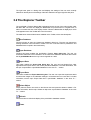
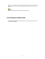
proVISION-II™ Explorer
User Manual
PIV Data Management
Copyright © 2000, 2006 Integrated Design Tools, Inc.
Software Release
2.02
Document Revision
August 2006
Products Information
http://www.idtvision.com
North America
2074 Centre Pointe Blvd
TALLAHASSE FL 32308
USA
P: (+1) (850) 222-5939
F: (+1) (850) 222-4591
[email protected]
Europe
via Pennella, 94
I- 38056 - Pergine Valsugana (TN)
ITALY
P: (+39) 0461- 53 21 12
F: (+39) 0461- 53 21 04
[email protected]
Copyright © Integrated Design Tools, Inc.
The information in this manual is for information purposes only and is subject to change
without notice. Integrated Design Tools, Inc. makes no warranty of any kind with regards to
the information contained in this manual, including but not limited to implied warranties of
merchantability and fitness for a particular purpose. Integrated Design Tools, Inc. shall not be
liable for errors contained herein nor for incidental or consequential damages from the
furnishing of this information. No part of this manual may be copied, reproduced, recorded,
transmitted or translated without the express written permission of Integrated Design Tools,
Inc.
2
Table of Contents
1
BEFORE YOU START....................................................................................................... 4
1.1
2
SYSTEM OVERVIEW ........................................................................................................ 5
2.1
2.2
3
OVERVIEW .................................................................................................................. 11
SESSION ..................................................................................................................... 12
CALIBRATION............................................................................................................... 12
ACQUISITION ............................................................................................................... 13
ANALYSIS .................................................................................................................... 13
STRUCTURE OF THE TREE VIEW ................................................................................... 14
HOW TO… ....................................................................................................................... 16
5.1
5.2
5.3
5.4
5.5
5.6
5.7
6
THE EXPLORER PANES .................................................................................................. 6
THE EXPLORER TOOLBAR .............................................................................................. 7
THE EXPLORER ADDRESS BAR....................................................................................... 8
THE EXPLORER MENU ................................................................................................... 9
THE PROVISION DATABASE ........................................................................................ 11
4.1
4.2
4.3
4.4
4.5
4.6
5
SYSTEM REQUIREMENTS ................................................................................................ 5
SOFTWARE INSTALLATION .............................................................................................. 5
THE EXPLORER GUI ........................................................................................................ 6
3.1
3.2
3.3
3.4
4
USING THIS MANUAL ..................................................................................................... 4
CREATE A NEW PROVISION DATABASE ........................................................................ 16
OPEN/DISPLAY A PROVISION DATABASE...................................................................... 17
IMPORT DATA IN A PROVISION DATABASE .................................................................... 18
EXPORT DATA FROM A PROVISION DATABASE .............................................................. 23
DELETE AN OBJECT FROM A PROVISION DATABASE ...................................................... 24
EDIT THE EXPLORER USERS LIST ................................................................................. 25
EDIT THE EXPLORER GENERAL OPTIONS ...................................................................... 26
APPENDIX ....................................................................................................................... 27
6.1
IMAGE FORMATS ......................................................................................................... 27
3
1 Before you start
1.1 Using This Manual
The on-line documentation of the IDT proVISION™ Explorer application and its components is
divided into the following parts:
System Overview
This section contains general information about the computer system requirements and the
installation of the software.
The Explorer GUI
This section describes the components of the proVISION™ Explorer Graphical User Interface:
the menu items and their functionality, the toolbar buttons and the panes of the explorer main
window.
The proVISION Database
This section describes the general proVISION™ database format and its main components.
How To…
This section provides detailed step-by-step instructions on the following tasks:
•
Create a new proVISION™ database.
•
Open/Display a proVISION™ database.
•
Import Data to a proVISION™ database.
•
Export Data from a proVISION™ database.
•
Delete an object from a proVISION™ database.
•
Edit the proVISION™ Explorer Users List.
•
Edit the proVISION™ Explorer General Options.
Appendix
This section contains some additional information.
4
2 System Overview
2.1 System requirements
The minimum system requirements to work with the proVISION™ software are:
•
PENTIUM™ processor or above.
•
Windows NT™ 4.0, Windows 2000™ Professional or Windows XP™ Operating Systems.
•
256 MB RAM.
•
500 MB free Hard Disk space for full installation.
2.2 Software Installation
Please refer to the 'Software Installation' topic on the "proVISION User Manual".
5
3 The Explorer GUI
3.1 The Explorer Panes
The proVISION™ Explorer main window is divided into three panes, one on the left side of the
window, the others on the right.
Left Pane
The left pane is a tree view and displays the tree structure of the proVISION™ database. The
tree view structure reflects how the proVISION™ database is organized.
Right Upper Pane
The right upper pane is a list view and displays the sub-items of the tree node currently
selected on the left pane. If a tree node has no sub-items, the view displays the tree items on
the same level of the selected one. The user can change the way the items are displayed by
pressing the Views Button on the main toolbar.
Right Lower Pane
6
The right lower pane is a dialog view and displays the settings of the tree node currently
selected on the left pane or the settings of the item selected in the upper right list view pane.
3.2 The Explorer Toolbar
The proVISION™ Explorer Buttons Bar is displayed across the top of the main window under
the Menu Bar. The user can display the Buttons Bar for quick access on a regular basis, or
hide it to increase the size of the display window. When the Buttons Bar is displayed, a check
mark appears next to the Toolbar item in the View menu.
The table below shows all the buttons available on the Toolbar, with a short description:
New Database
Press this button to open the 'Create new database' dialog box. The user may browse the
existing directories in the hard disk or create a new one. If the OK button is pressed the root
database files are copied in the new directory.
Open Database
Pressing this button enables the proVISION™ Explorer Open dialog box. The user can
browse the directories in the hard disk or in the LAN for the database. Directories that contain
the file proVISION.mdb are the only ones recognized as a valid.
Import Data
This button enables the Import data dialog box. The user can load images from other
applications and import them in the current proVISION database. For further information, see
the topic “Import Data in a proVISION Database” in the “How To…” section.
Export Data
This button enables the Export data dialog box. The user can export the experiments result
as well as the images or the calibration settings in a Word document or a text file. For further
information, see the topic “Export Data from a proVISION™ database” in the “How To…”
section.
Delete Object
Simply select a session tree node on the left tree view and press this button to delete it. For
further information, see the topic “Delete an object from a proVISION™ Database” in the “How
To…” section.
Refresh
Press this button to refresh the display of the proVISION™ database contents.
Views
7
Allows the user to change the way the objects are displayed on the upper right view pane of
the main window. There are four different viewing modes (Large icons, small icons, List,
details).
Help
This button displays the on-line help documentation (this document)
3.3 The Explorer Address Bar
The address bar is located below the main toolbar and It contains a list of the sessions of the
current proVISION database.
8
3.4 The Explorer Menu
3.4.1 File Menu
New
The selection of this item opens the 'Create new database' dialog box. The user may browse
the existing directories in the hard disk and in the LAN or create a new directory. If the OK
button is pressed the root database files are copied in the new directory and the user can start
new proVISION sessions.
Open
The Selection of this item enables the proVISION™ Explorer Open dialog box. The user can
browse the directories in the hard disk, or in the LAN, for the directory where the database is
located. The Explorer recognizes as valid database locations the directories where the file
proVISION.mdb is found. Changes to the currently selected database are reflected on the
proVISION™ settings.
Delete
This option deletes the tree node selected in the left tree view of the main window and the
corresponding directory in the proVISION Database. The menu item is grayed if the current
item cannot be deleted. The items that can be deleted are: Sessions, Calibrations (except the
_No_Calib folder), acquisitions (except Acquisition 000), Analysis (except Analysis 000). If an
Acquisition or Analysis folder is deleted the application renames the remaining folders.
Exit
Select this item to exit the proVISION™ Explorer application.
3.4.2 Tools Menu
Import
The Import option is a very powerful tool that allows the user to import external images and
configuration files into the proVISION™ database. For further information, refer to the “Import
data in a proVISION Database” in the “How To…” section.
Export
The proVISION™ database data can be exported to word or text documents. The user selects
a tree view item in the left tree pane of the main window and presses the Export menu item. A
dialog box appears: the user can choose the format of the export file and press OK. The
Explorer automatically creates a file with the exported data. For further information, refer to the
“Export Data from a proVISION Database” in the “How To…” section.
Users
The selection of this item opens the Users dialog box. A list of all the users names stored in
the database is displayed. It is possible to Add, Edit or remove Users from the list and update
the changes in the database. For further information, refer to the “Edit the Explorer Users List”
in the “How To…” section.
9
Options
The selection of this item opens the “General Options” dialog box. A set of check box allows
the user to add filters to the display of the database records. For further information, refer to the
“Edit the Explorer General Options” in the “How To…” section.
3.4.3 View Menu
Standard Toolbar
The Explorer Buttons Bar can be displayed for quick access on a regular basis, or hidden to
increase the size of the display window. When the Buttons Bar is displayed, a check mark
appears next to the Standard Toolbar item in the Toolbars submenu of the View menu.
Address Bar
The Address Bar can be displayed or hidden to increase the size of the display window. When
the Address Bar is displayed, a check mark appears next to the Address Bar item in the
Toolbars submenu of the View menu.
Status Bar
The Explorer Buttons Bar can be displayed or hidden by selecting this menu item. When the
Status Bar is displayed, a check mark appears next to the Status Bar item in the View menu.
Image Pad
The Image pad is a dialog box which can be activated when a sequence of images is displayed
in the Explorer's right lower pane.
Large Icons, Small Icons, List, Details
The items in the Explorer's right upper pane may be displayed in four different ways: large
icons, small icons, list and details. Click on one of these menu items to select the preferred
one.
Refresh
Select this item to refresh the display of the proVISION™ database contents.
3.4.4 Help Menu
Contents
This item displays the on-line help documentation (this document).
About
This item opens the "About" dialog box. It shows the provision information, the version and the
copyright notice.
10
4 The proVISION Database
4.1 Overview
The images, the system configuration files and the results are automatically organized in a
specific directory structure. There are four different levels in the directory structure:
•
Session.
•
Calibration
•
Acquisition
•
Analysis
Each level has a different meaning and shares its settings with all the child sub-levels.
11
4.2 Session
The session is the first level in the directory hierarchy. When the camera acquisition is initiated,
a new session directory can be created or an existing session directory can be opened. In the
session directory a configuration file saves the following session information:
1. Session Name.
2. Date and time of directory creation.
3. The name of the User who created the session.
4. A brief description of the session (comment).
5. The camera selected when the session was created.
6. The laser type selected when the session was created.
Each session folder may contain more calibration subfolders.
NOTE: the proVISION application can acquire images from three different sources in a 3D system:
one camera (camera A), the other one (camera B) or both (3D Images). The images acquired from
the three different sources are stored in the database with different names (ImgA.xxx, imgB.yyy,
Img3D.zzz). The Explorer displays the images in separated tree nodes, by adding a further tree
level below the session.
4.3 Calibration
When a new session is created or an existing one is opened, a _No_Calib subfolder is
automatically created in the session directory. This folder will contain the entire images folder
that will be processed without calibration.
If one or more calibration images are acquired and saved the program prompts the user for a
name. The calibration images are automatically saved and the name is used to create a new
directory under the session in which the calibration images will be stored. At this point the user
also has the opportunity to generate a calibration file from the stored images. Different files are
saved for camera A, camera B, and 3D calibrations.
Additional settings that relate to the calibration are saved in the same folder:
Motor Settings: the positions of the focusing system motors.
12
4.4 Acquisition
A new acquisition folder is created any time a set of acquired images is saved. The folder
Acquisition000 is reserved for on-line processing and does not contain stored images.
Additional settings that relate to the Acquisition are saved in the same folder.
Laser Settings: all the timing values displayed in the proVISION “Timing/Laser” dialog box in
(laser frequency, Q-switch delays, laser pulse separation, etc).
Camera Settings: all the settings of the camera used for the acquisition (exposure, contrast,
brightness, binning, polarities, etc.).
Color Mapping: a color map look-up table can be configured for the acquired images.
Mask Image: masking is operated using a binary image overlapped to the acquired images.
The image is black and white. White pixels are transparent, while black ones hide the
corresponding points of the acquired image.
4.5 Analysis
The Analysis level is the lowest level in the tree hierarchy. The analysis folders contain the
results of the PIV calculations. Any folder has a progressive index and its own different
configuration file for Camera A, camera B and 3D images.
PIV Settings: Stores the specific parameters used during the analysis such as: Correlation,
Mesh, Filters, Vectors, Histogram and Output.
PIV Results: Contains the plot files generated for each calculation.
Tecplot Layout files: contains the *.lay files used to display the result data.
13
4.6 Structure of the Tree View
The Explorer tree view on the left side of the main window reflects the organization of the
proVISION Database and visualizes the data in an easy way.
The root of the tree view is the Database node which contains the Session nodes. Each
session is structured as in the figure below.
Session
Cam A (2 D)
Cam B (2 D)
Cam A+B (3D)
_No_Calib
Calibration
Calibration Settings
Motors Settings
Acquisition 000
Acquisition 001
Settings
Laser Settings
Camera Settings
Images Settings
Images
Img3D.m pt
Analysis 000
Analysis 001
PIV Settings
Correlation
Mesh
Filters
Vectors
Histograph
Output
PIV Results
Img3D.plt
The main nodes levels of the tree are:
14
4.6.1 Session Level
Each session has its own configuration parameters: Session name, User name, date, time,
camera model and laser model.
4.6.2 Camera Selection level
This level is not present in the directory structure of the Database. It has been added to
separate the settings and the images acquired with the first camera (Camera A), the second
camera (Camera B) and both the cameras (3D images with Camera A+B).
4.6.3 Calibration Level
The third level contains the _No_Calib node (images acquired without calibration) and the
nodes of any performed calibration. It contains also the motor settings (this nodes is displayed
only if the "Display Motors Settings" option is checked). Each calibration node contains its
acquisitions nodes.
4.6.4 Acquisition Level
The Acquisition nodes contain three different kinds of sub-nodes: the Settings folder which
includes the Laser Settings, the Camera Settings and the Images Settings (Color Map and
Mask Image); the Images folder which contains the acquired images; the Analysis folders.
4.6.5 Analysis Level
Each Analysis node contains the Settings folder (Correlation, Mesh, Filters, Vectors, Histogram
and Output) and the Results folder (plt files).
15
5 How to…
5.1 Create a new proVISION Database
The user can browse the directories in the hard disk or in the LAN and set the directory where
his database will be located:
1. From the menu toolbar, select “File” then “New DB…” or from the Buttons toolbar press the
“New DB”. The Windows Explorer Open dialog box appears.
2. Use the Open dialog box to browse the resources of your computer or the Local Area
Network.
3. If the directory you select for the new database does not exist, create it by clicking the
'Create New folder' button at the top right side of the dialog box
4. Double click on the directory you just created and press OK.
16
.
5.2 Open/Display a proVISION database
The user can browse the directories in the hard disk or in the LAN and set the directory where
his database is located:
1. From the menu toolbar, select “File” then “Open DB…” or from the Buttons toolbar press
the “Open DB”. The Windows Explorer Open dialog box appears.
2. Use the Open dialog box to browse the resources of your computer or the Local Area
Network.
3. Select a valid provision.mdb file and press the OK button.
NOTE: the Explorer recognizes as valid database locations only directories that contain the
proVISION.mdb file. If the currently selected database location changes, this change is
automatically reflected in the proVISION™ settings.
17
5.3 Import data in a proVISION database
VERY IMPORTANT NOTE: Before reading this topic, you should read the “proVISION Database“
topic in order to understand the tree structure of the database.
From the menu toolbar, select “Tools” then “Import…” or from the Buttons toolbar press the
“Import” button. The Import Wizard will start. The wizard is divided into three or four sections
depending on the type of imported images.
5.3.1 Step #1 - Images
The check boxes at the top of the dialog box allow the user to select what kind of images he
wants to import.
The “I want to import images for Camera A.” and “I want to import images for Camera
B.” options allow importing single view images (2D) which will be renamed to ImgAxxx.yyy (if
the option A is selected) or ImgBxxx.yyy (if the option B is selected). Then the user must
press the first button below the Images list to browse the computer and load the single camera
images to import.
The “I want to import 3D images.” option allows the simultaneous import of images from
camera A and B and tiling them to create 3D images. In this configuration both the “Cam A
Imgs...” and “Cam B Imgs…” buttons are enabled and the user must press both of them in
order to load the images to import.
Delta T: the value is the time between two laser pulses and it is used by proVISION™ to
compute the particles velocity.
18
Pixel Depth: if the images have 10 or 12 bit pixel depth, the user may edit it; otherwise the
control is grayed out.
NOTE: if the user just wants to import calibration images, the user may select one of the
top options and press next without loading any image.
5.3.2 Step #2 - Session
The second step of the wizard helps to identify which session will contain the imported images.
The user may create a new session folder or select a session from the database.
1. New Session: if you the New Session option is selected, some values should be entered:
Session Name: the name of the session folder.
Comment: a brief description of the Session (optional).
Camera: select the camera used in the image acquisition from the list. If none of the
models correspond to the camera used to acquire the images, the option “Other camera”
must be selected.
2. Import into an existing session: the images may be stored in one of the Session folders
in the provision database.
19
5.3.3 Step #3 - Calibration Folder
The imported images may be associated to a calibration folder.
1. No Calibration: the images are imported in the _No_Calib subfolder of the session.
Neither calibration settings nor images are associated to the images.
2. Create a new calibration folder and import calibration images: the calibration folder
name must be entered. The calibration images and the settings (optional) will be imported.
The import of the images and settings is described in the next topic.
3. Import from an existing calibration: the images can be imported into a subfolder of a
predefined calibration. If the selected session does not contain any calibration folder the
option is disabled.
20
5.3.4 Step #4 - Calibration Images
If the option “Create a new calibration folder” is selected in the Calibration Folder Step, the user
must import the calibration images.
2D images: if single camera images are imported (option 1 or 2 in the first wizard step), a
single calibration image must be imported. The user may press the “Cam A Imgs…” button and
import a single camera calibration image.
3D images: the procedure is similar to the one of the step #1. Both camera A and camera B
images must be imported. Two scenarios are available:
Standard calibration: if the user wants to perform a standard calibration, a single 3D image
is required. The user must import a single image for each camera.
Distorted calibration: if the user wants to perform a distorted calibration, at least five 3D
images are required. This means that at least 5 images from camera A and 5 from camera B
are required. Also, for each image pair, the Z position is required. To enter the Z position,
select the image from the Camera A column and enter the value in the edit box below. The
first image position is 0 and cannot be edited.
21
5.3.5 Step #5 - Summary
A summary of the selected settings is shown at the end of the import procedure. The user may
press “Finish” to import the images or “Back” to review or change any setting.
22
5.4 Export data from a proVISION database
By pressing the Export button on the main toolbar, a dialog box appears:
The database records can be exported in two different formats (Word Document or simple Text
File).
There are four different kinds of records that can be exported:
•
Session: the session and all its calibrations, acquisitions and analysis are exported.
•
Calibration: the calibration and all its acquisitions and analysis are exported.
•
Acquisition: the acquisition and all its analysis are exported.
•
Analysis: the analysis is exported.
To export a database record:
1. Select the object by clicking on the corresponding tree node in the Explorer left tree view.
2. From the menu toolbar, select “Tools” and then “Export…” or from the Buttons toolbar
press the “Export” button. A dialog box appears.
3. The upper grayed edit box shows the name and the type of object you will export.
4. If the exported object is a session and contains images 2D and 3D, the camera selection
allows selecting the type of images to export (A, B or 3D). Refer to the “proVISION
Database” for further information.
5. The “File path Name” edit displays the full path of the file to export. Press the Browse
button to change the directory and the name of the file.
6. The templates list shows you the available file type. Select one, and then press OK.
7. The record will be exported and a message box will ask you to display the file.
23
5.5 Delete an object from a proVISION database
The current item of the tree view can be deleted by pressing the "Delete" button in the main
toolbar. The corresponding directory in the proVISION Database will be deleted. The menu
item is grayed if the current item cannot be deleted. The items that can be deleted are:
Session: each session can be deleted.
Calibrations: each calibration created by the user except the _No_Calib one can be deleted.
Acquisition: each acquisition except Acquisition 000 can be deleted. After any deletion the
program renames the remaining folders because the.
Analysis: each analysis except Analysis 000 can be deleted. After any deletion the program
renames the remaining folders.
Warning: The deletion of a folder requires Administrator privileges.
24
5.6 Edit the Explorer Users List
One of the parameters that must be configured when opening a new session in the proVISION
application is the user. The list of all the users is stored in the database and can be edited:
1. From the menu toolbar, select “Tools”, then “Users…” A dialog box appears.
2. The list of all the stored users is displayed. You can:
•
Add User: press the Add button and insert the user’s name and a comment.
•
Edit User: press the “Edit…” button and edit the user’s name and comment.
•
Delete User: press the “Delete…” button and answer yes to the question that follows.
25
5.7 Edit the Explorer General Options
You can choose what kind of records to display in your database. From the menu toolbar,
select “Tools”, then “Options…” A dialog box appears.
•
Show camera A records: if this check box is unchecked, the Explorer does not display
the entire camera A acquisition images and settings.
•
Show camera B records: if this check box is unchecked, the Explorer does not display
the entire camera B acquisition images and settings.
•
Show 3D cameras records: if this check box is unchecked, the Explorer does not display
the entire 3D acquisition images and settings
•
Display motors settings: if this check box is unchecked, the Explorer does not display
the motor settings dialog box.
26
6 Appendix
6.1 Image Formats
The image formats supported by proVISION Explorer are the following:
•
TIFF files.
•
Windows™ Bitmap Files.
•
PCX Files.
•
Multi-page TIFF Files (MPT).
•
Multi-page PCX Files (DCX).
•
Multi-page RAW Files (MRF). This is an IDT proprietary format.
27