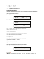
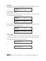
1
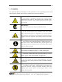
VSP 516 Series User Manual
RGBlink Science & Technology Co., Ltd.
The pictures and data in the user manual are reference only, check the real
product please!
CONTACT US
Headquarter: S603 Weiye Building Torch Hi-Tech Industrial Development Zone
Xiamen,Fujian Province, P.R.C
Shenzhen office: Room A05, Floor 4, Building 24, Industry factory Nanshan
Science & Technology Park, Shenzhen, Guangdong Province, P.R.C
Tel: +86-592-5771197
Fax:+86-592-5771202
E-mail:[email protected]
http://www.rgblink.com
Revision
Format
Time
ECO#
Description
Principal
Release
Lisa
1.0
2010-1-15
0000
1.1
2010-3-11
0001
Compare table of AVDSP
1.Add
more
Lisa
supported
output
resolutions; Page:4
1.2
2010-7-20
0002
2.Add the adjustable feature of
DE;Page:11-12
3.Explain
the
limits
of
Lisa
scale;
Page:14
1.3
2010-8-9
0003
Add prompt to save function
1.4
2010-10-22
0004
1.Compared
to
Lisa
VSP516
and
Lisa
VSP516H, VSP516S can install
SDI input module;
2. VSP516S Baud Rate is 115200,
while VSP516 and VSP516H is
9600;
3. The User’s Manual add the
instruction on how to use USB
port
to
work
with
console
software and LINSN software.
1.5
2010-11-4
0005
Add a note about how to use LINSN
Software.
Lisa
CONTENT
1.0 Safety ........................................................................................... 1
2.0 Specification .................................................................................. 2
2.1 Parameters............................................................................... 3
3.0 Connection .................................................................................... 5
3.1 VSP 516 Back Panel................................................................... 5
3.2 How to install ........................................................................... 7
4.0 Front Panel Keyboard Operation........................................................ 8
4.1 VSP 516 series Operator Guideline............................................... 8
4.2 Video Processor Menu ...............................................................11
5.0 Communication Software Guideline ..................................................17
5.1 Install Software .......................................................................17
5.2 Run AVDSP Console ..................................................................21
6.0 FAQ .............................................................................................31
6.1 No output in target display ........................................................31
6.2 VGA input could not work with AVDSP Console .............................31
6.3 DVI input could not work with AVDSP..........................................31
6.4 Component input could not work with AVDSP ...............................32
6.5 User settings can not save.........................................................32
6.6 Can’t update main board software ..............................................32
7.0 Quick Start ...................................................................................33
7.1 Single-screen control ................................................................33
7.2 How to control processor with console software by USB?................35
7.3 How to Use LINSN Ledset software?............................................39
8.0 Appendix ......................................................................................41
8.1 AppendixⅠDownload the IP software ..........................................41
8.2 Appendix Ⅱ How to add tasks. ...................................................43
1.0 Safety
The general safety information in this summary is for operating person. Any
requirement, please feel freely to contact our service engineer.
Power Source
This product is intended to operate from a power source
between 85~265 volts rms . This product is only workable under
correct power condition, which is already mark on the back panel
of the power.
High Voltage
There are many high voltage components inside.
Do not Remove Covers and Panels
Do not remove Covers in any conditions. There are not any
spare components inside for maintenance, so do not maintain
this product by userrselves, any requirement, please feel free to
contact our service engineer. Keep heavy device from power
cord.
Grounding the Product and Use the Proper Fuse
This product is grounded through the grounding conductor of
the power cord. To Avoid electrical shock, plug the power cord
into a properly wired receptacle before connecting to the product
input or output terminals.
Keep away from Magnet, Motor, TV and Transformer.
Guard Against Damp
Keep using inside clean and dryness environment, once the
device get wet, must remove power cord right now.
Keep away Exploder
Do not operate the device inside dangerous and easy
explosive gas, which it may make fire, blast or something without
expectation.
Keep away Pour Liquid and Fragment
It is forbid to pour liquid, metal fragment or anything else
inside this device to avoid fire and other accident. Once that
happens, must remove power cord and try to make it clean
before power on again.
VSP 516 Series User Manual
Doc. No:RGB-RD-UM-V516E001
1
2.0 Specification
AVDSP series video processors are designed by the latest high performance
image processing technology. AVDSP can handle following video without limit,
include CVBS(Composite)、S-Video (YC)、YCbCr、YPbPr、RGBHV(VGA)、
DVI-D、HDMI、SDI(SD-SDI、HD-SDI) and VOIP(Copper RJ45).
Compare table of AVDSP as following.
VSP 516 Series User Manual
Doc. No:RGB-RD-UM-V516E001
2
2.1 Parameters
Composite BNC Input
Number of Inputs
3
Supported Standards
PAL/NTSC; 480i,576i
Signal Level
1Vpp±3db (0.7V Video+0.3v Sync ) 75ohm
S-video DIN4 Input
Number of Inputs
1
Supported Standards
PAL/NTSC; 480i,576i
Signal Level
Y:1Vpp±3dB
(0.7V Video+0.3v Sync ) 75ohm
U/V:0.7Vpp±3dB 75ohm
YPbPr BNC Input
Number of Inputs
BNC*3
Supported Standards
Anologue HD Input
480i,576i,480p,576p,720p50,720i60,1080i50,1080p50
1080i50,1080i60
Signal Level
Y:1Vpp±3dB
(0.7V Video+0.3v Sync ) 75ohm
Pb/Pr:0.7Vpp±3dB 75ohm
VGA DB15 Input
Number of Inputs
1
Connector
Standard DB15 socket
Supported Standards
VGA-UXGA;
1024×768×60, 800×600×60, 640×480×60
Signal Level
R、G、B、Hsync、Vsync:0 to1Vpp±3dB
(0.7V Video+0.3v
Sync ) 75ohm
black level:300mV Sync-tip:0V
DVI Input
Number of Inputs
1
Connector
Standard DVI-I socket
Supported Resolution
SMPTE:625/25 PAL, 525/29.97 NTSC, 625/50p PAL,
525/59.94p
NTSC:1080i50,1080i59.94/60,720p50,720p59.94/60
VESA:800×600×60Hz,1024×768×60Hz,1280×768
×60Hz,1280×1024×60Hz,1600×1200×60Hz,1920
×1080×60Hz,1920×1080×50Hz
Signal Level
TMDS pwl,single pixel input,165MHz bandwidth
Standard
HDMI 1.3
SDI Input (Optional module)
Number of Inputs
1
Connector
BNC
Data Rate Range
19.4Mbps~1.5Gbps
Supported Standards
ITU-R BT.656,ITU-R BT.601,SMPTE 259M, SMPTE 292,
VSP 516 Series User Manual
Doc. No:RGB-RD-UM-V516E001
3
SMPTE 297
Equalization)
Belden 1694A 100M HD1.485G,350m SD 270Mbps
Audio Input
Number of Inputs
10
Connector
Standard RCA socket
Audio Standard
48Kbps 24bit balance analog audio
DVI Output
Number of Inputs
1
Connector
Standard DVI-I Interface
Signal Level
TMDS pwl, 165MHz bandwidth
Supported Standards
VESA:800×600×60Hz,800×600×75Hz,1024×768
×60Hz,1024×768×75Hz,1280×1024×60Hz, 1920
×1080P×60Hz
VGA Output
Number of Inputs
1
Connector
Standard DB15 socket
Supported Standards
VESA:800×600×60Hz,800×600×75Hz,1024×768
×60Hz,1024×768×75Hz,1280×1024×60Hz, 1920
×1080P×60Hz
R、G、B、Hsync、Vsync:0 to1Vpp±3dB
Signal Level
(0.7V Video+0.3v
Sync ) 75ohm
black level:300mV Sync-tip:0V
Audio Output
Number of Outputs
1
Connector
Standard 1/4” socket
Audio Standard
48Kbps 24bit balance analog audio
Function
Source Switch
support every signal alpha key operation
PIP
PIP for SD with HD and HD with HD
AV Sync
supported
Extras
Communication
RS232 USB TCP/IP
Power Supply
85-264V 2A IEC-3
Working Environment
0°C~45°C
Stored Environment
10% to 90%
Product Warranty
1 year
VSP 516H is different from VSP 516 as following output resolution.
800×600×75Hz,1024×768×75Hz,1280×768×60Hz
Note:
1920×1080p×60Hz
Specifications are subject to change without notice.
VSP 516 Series User Manual
Doc. No:RGB-RD-UM-V516E001
4
3.0 Connection
3.1 VSP 516 Back Panel
1、Dial the code switch;
2 、 10/100M interface (copper RJ45). Used to connect the computer by
568B-568A twist-pair;
3、USB interface,Used to connect the computer;
4、RS232 interface (RJ11) for AVDSP processor. Used to connect the computer;
5-14、Audio interface, support audio signals from DVD player or audio sources;
15-16、Gigabit copper port, connect to LED screen;
17、Gigabit Transmitter card power interface, not use inside case;
18、Gigabit Transmitter card USB control interface.
19、Gigabit Transmitter card DVI input,connect to DVI output of VSP 516.
(This Connection does not support hot-plugging)
20、SDI Input BNC, used to support SD/HD SDI input。Input the video signal
from the HD player, HD projector. (SDI input is the optional module)
Note:
VSP 516S can install a SDI input module to support SD-SDI and
HD-SDI signal, compared to VSP 516 and VSP 516H.
VSP 516 Series User Manual
Doc. No:RGB-RD-UM-V516E001
5
21-23、Composite input interface,Composite BNC. Used to input composite
signal (PAL, NTSC, SECAM compatible);
24 、 S-Video DIN 4, used to input S-Video signal ( PAL, NTSC, SECAM
compatible);
25、DVI input interface。Input the video signal from computer, DVI signal
generator. Connect to the same DVI interface on VSP 516;
(This Connection does not support hot-plugging)
26-28、R/Pr G/Y B/Pb BNC, used to support SD/HD analog video input, up to
1080p60;
29、VGA input interface, DB-15, used to support Analog RGB input; Connect to
the VGA interface on the VSP processor.
30、AUDIO output interface2,connect to the audio player。
31、DVI output interface,connect to the monitor or LED screen which has DVI
interface. (This Connection does not support hot-plugging)
32、VGA output interface, connect to the monitor, projector and so on;
33-34、Switch and power. It must use IEC-3 power line. Always ground to avoid
electric shock.
VSP 516 Series User Manual
Doc. No:RGB-RD-UM-V516E001
6
3.2 How to install
VSP 516 frame size
VSP 516S has the same frame size of VSP 516H and VSP 516S;
Note:
VSP 516 Series User Manual
Doc. No:RGB-RD-UM-V516E001
7
4.0 Front Panel Keyboard Operation
Insert power cord and push power to ON position. LCD module on the front
panel will show RGBLINK and go into self verification before it load last setting
config and send processed image to the target monitor. For the first setup, CV1
input is default source. With front panel keyboard, user can operate VSP with
menu display on LCD module.
4.1 VSP 516 series Operator Guideline
VSP 516 series front panel as following:
1. LCD Module;
2. Keyboard:
ESC: push to exit from current choice item;
SEL: push to confirm the current choice item;
UP: push to select up items in LCD menu;
DOWN: push to select down in LCD menu;
LEFT:push to select the left items
RIGHT:push to select the right items
CV1:switch to composite 1 input
CV2:switch to composite 2 input;
CV3:switch to composite 3 input;
SVID:switch to SVideo;
VGA: switch to analog RGB input;
YPbPr: switch to high definition component,
DVI: Switch to DVI input
+:Switch to amplify the audio;
-:Switch to down scale the audio;
VSP 516 Series User Manual
Doc. No:RGB-RD-UM-V516E001
8
SDI: SDI input, compatible with HD/SD SDI, push to switch to SDI input;
VSP 516S can install a SDI input module to support SD-SDI and
HD-SDI signal, compared to VSP 516 and VSP 516H.
Note:
PBP:Switch to show two pictures in side by side mode;
VSP516S front panel remove PBP mode button to SDI button;
VSP516 and VSP516H front panel keep PBP mode button, but
remove SDI button.
Note:
PIP:Switch to show picture in picture on the screen. CV1 is the default
small picture on the top left corner,
DVI is the default picture with full screen.
SAVE1:switch to use the user-defined mode 1;
SAVE2:switch to use the user-defined mode 2;
SAVE3:switch to use the user-defined mode 3;
FS:switch to selet full screen or zoom view, just for single picture mode;
RATIO:switch to select aspect ratio 4:3 or 16:9;
MSA:switch to select the audio channel which send to output in multi
picture mode;
MUTE:Switch to select mute sound or return;
MENU:push to go to main menu;
FRE:push to freeze the video image or live again;(FreezeÆLiveÆFreeze)
AB: Channel Switch, only works under the PBP mode. Push it to switch between
the picture of main channel and the picture of subchannel. For instance, if
processor now works under subchannel mode, user can switch channels in
subchannel; be under subchannel mode if you push Reset button.
AB in VSP 516 doesn't support Fade-In-Out.
Note:
VSP 516 Series User Manual
Doc. No:RGB-RD-UM-V516E001
9
SCALE: push to go to between scaleÆzoomÆcropÆscale mode;
BRT:push to adjust the brightness and the contrast ratio, push to enter
to the relevant Menu, and then push the UP and DOWN to adjust the
brightness and the contrast ratio.
OUT: push to select the output format by using the UP and DOWN.
I/II: push to set single or dual channel
SAVE: push to save current config.
VSP 516 Series User Manual
Doc. No:RGB-RD-UM-V516E001
10
4.2 Video Processor Menu
System menu as follows;
>VSP 516
*Dev Info
Recall
↓
Fig. 1
The first line shows VSP 516.
Push the right and left direction key to select the left or right menu. Before
the menu item, if there is a * sign, means the menu item has been selected,
you can push the Select key to enter it.
The ↑ on the right means you can select the menu items by pushing the up
and down direction key.
User can check the information of the equipment in “Dev Info” menu
(including the manufacturer、serial-number );
User can get more service and support according to the serial-number.
RGBlink Co ltd.
>SN:3204
User can check current input and output sources in Dev Info menu also.
Input: CV1 1024x768x60
Output: CV2 1024x768x60
Touch UP/DOWN to check customer service E-mail and web site address;
User can visit company web site for more product information.
[email protected]
www.rgblink.com
Touch UP/DOWN to check System time
System time:
2009-08-17
15:12:35
User can do a Factory Settings in Recall menu, after successful reset you will
see the menu as follows:
VSP 516 Series User Manual
Doc. No:RGB-RD-UM-V516E001
11
Factory reset was completed !
Push the MENU to enter the main menu, then push up and down direction
key, the menu as follows:
>VSP 516
*Language
Alpha
↑
Push the LEFT/RIGHT to select the relevant submenu.
LANGUAGE submenu as follows:
*LANGUAGE
>Chinese
English
Push UP/DWON to enter Alpha setup, user can set value from 0 to 100,
0 means video or graphic would be disappear and 100 means normal;
Port A and Port B stand for two channel picture;
*Alpha
Port A Value:
100
Push OUT to enter the Output menu, push the UP or DOWN to select
different output resolution, push OK to confirm the output resolution.
Advance submenu as follows:
① VSP516H and VSP 516S support the minus pixel shift
function, which VSP 516 can not support;
Note:
② VSP516H and VSP 516S can not support pixel shift on the
resolution 1920×1080P×60Hz.
Pixel shift to minus:
Press UP/DOWN and select the menu as shown in Figure 1:
>VSP 516
*Advance
XY_Pos ↑
Figure 1
Press LEFT/RIGHT and select XY_Pos to enter the submenu of adjusting
effective area;
VSP 516 Series User Manual
Doc. No:RGB-RD-UM-V516E001
12
H_BLANK
*HS:
46
V_BLANK
*VS:
38
XY_Pos:The sub-menu of which is used to adjust the position of overall
effective area shown on the screen or monitor.
H_BLANK: The overall effective area can be moved around by adjusting the
value of H_BLANK.
V_BLANK: The overall effective area can be moved up and down by
adjusting the value of V_BLANK.
Screen parameter:
Hsize:
1024
Step:user can set the step of scale;
HSize:set the horizontal size of the image;
VSize:set the vertical size of the image;
HPos:set the horizontal position of the image;
VPos:set the vertical position of the image;
User can set size and position of the screen simply, Mainly applies to LED
screens users. After setting screen parameter, the user choice PIP or PBP
operation, display picture can directly shows on corresponding screen。
Output
>1024x768x60
Push theⅠ/Ⅱto enter Single or Dual channel menu , push the UP / DOWN to
select the single or dual channel, push SEL to confirm the single channel or dual
channel work state;
Setup
Dual
Setup
Single
Select the input channel, push the UP/DOWN, and SEL to confirm the
VSP 516 Series User Manual
Doc. No:RGB-RD-UM-V516E001
13
different input channel. User can also push the channel name on the
keyboard to go into the input channel.
Source Select
>CV1
AB in VSP 516 is used to enable channel if dual channel mode.
Setup
A on B
OR:
Setup
A on B
Push SCALE to set the size and position of the image, push UP/DOWN and
SEL to confirm the relevant items;
Step:user can set the step of scale;
HSize:set the horizontal size of the image;
VSize:set the vertical size of the image;
HPos:set the horizontal position of the image;
VPos:set the vertical position of the image;
Scale
> Step
10
When shown in one single image, the ratio between the
horizontal and the vertical of the image should be equal to or
less than 3.
Note:
When shown in dual image, there is a limit of aspect ratio of the
image in the left side: The horizontal of the image in the left
side should be larger than that of the image in the right side.
This rule still need to be followed even if the images are dragged
to the opposite.
Push the FRE to freeze the live image or live the freeze image.
Freeze Frame
Once gain for live
OR:
VSP 516 Series User Manual
Doc. No:RGB-RD-UM-V516E001
14
Live Frame
Once gain for live
Push BRT to set the brightness and the contrast ratio:
VSP 516
Brightness
50 ↓
VSP 516
Contrast
50 ↑
OR:
Push SAVE and then push SAVE1 or SAVE2 to save the operation to SAVE1 or
SAVE2;Push SAVE1 or SAVE2 to execute relative operation after user save
the operation sucessfully.
Add prompt to save function
For VSP 516 series, when user push the SAVE key, the SAVE1、
Note:
SAVE2 and SAVE3 lights on the front panel will go on at the same
time, it reminds user must press SAVE1 or SAVE 2 to finish the
final save function.
Slelect Save Mode !
Push Esc To Exit
Touch FS button can realize screen switch between scale mode and full screen
mode.
Picture mode
Full Size
Picture mode
Small Size
Touch RATIO button,set screen width and height.
Size: 4:3
Size: 16:9
VSP 516 Series User Manual
Doc. No:RGB-RD-UM-V516E001
15
Size: Normal
MSA : touch the main sub-channel audio and audio channel switching
button,main channel will play sound.
Main window audio
Touch again, sub-channel will play sound.
Sub window audio
MUTE:mute the equipment, shown as the picture:
Mute
Touch MUTE again will revovery to play sound.
VSP 516 Series User Manual
Doc. No:RGB-RD-UM-V516E001
16
5.0 Communication Software Guideline
AVDSP video processor is very easy to be configured with user friendly
communication software, support drag and drop operation for edit and display.
Also can customized with schedule function.
5.1 Install Software
Dual click AVDSP.exe to install, select Chinese or English version for use,
after click “select ”to next dialog.
If user agree to install this software, please click next to go on, else click esc to
exit this install.
And in next dialog is the user agreement of the software, click agree to go on
and refuse to exit.
VSP 516 Series User Manual
Doc. No:RGB-RD-UM-V516E001
17
If users agree to the agreement, user can select install directory in next
dialog, else, click next to install software to default directory “C:\Program Files”.
Click “next ”to go on.
VSP 516 Series User Manual
Doc. No:RGB-RD-UM-V516E001
18
Click “next ”to go on.
Click “finish” and ready to run AVDSP console.
VSP 516 Series User Manual
Doc. No:RGB-RD-UM-V516E001
19
VSP 516 Series User Manual
Doc. No:RGB-RD-UM-V516E001
20
5.2 Run AVDSP Console
Run AVDSP.exe and the console will auto detect device in serial or networks by
detected Comm port and pro-define IP address.
After detect, open the device console, for example, if the device is VSP 618,
then VSP 618 console will be load, as following. Default loading is VSP 516 if can
not detect any device.
VSP 516 Series User Manual
Doc. No:RGB-RD-UM-V516E001
21
Setup Communication
AVDSP Console support COM port or Ethernet (UDP) to access AVDSP.For the
first running ,user must click the
to close COM Port. Click
to change
the COM Port and the Baudrate.
Serial: user can make choice between existent com ports and baud rates;
default Baudrate is 9600.
Ethernet: user can fill any number less than 1023 in Local Port. The Remote Port
must be 192.168.0.100 and the Remote Port must be 1000.
VSP516 and VSP516H work Baud Rate as 9600, while VSP516S
Baud Rate works as 115200.
Note:
The COM Port is decided by user’s COM. Right click my computer icon on
desktop, select HardwareÆDevice Manager in the system attributes dialog. The
COM in red in the picture is the COM user can make choice.
VSP 516 Series User Manual
Doc. No:RGB-RD-UM-V516E001
22
Then click
to open COM.
will display after success to
connect the COM.
If AVDSP console success to detect device in chain, the software version, device
core version, firmware version and serial number will display on the bottom
right corner of the screen.
5
How to use
Operator can check parameters by software.
: Save script. Save current user config parameters as script.
: Open script. User can open saved script.
VSP 516 Series User Manual
Doc. No:RGB-RD-UM-V516E001
23
: Import template. There are six templates for user.
: Export template. Export current config as template.
: Option. User can choose open device when start and using script saved
before or execute schedule edited before when start.
If user choose open device when start, user can use last run, use script file or
none when user start. User can click
to choose which script user want to
open.
If user choose execute schedule when start, the next dialogue will display when
software run.
VSP 516 Series User Manual
Doc. No:RGB-RD-UM-V516E001
24
: Language. The software supports Chinese and English version. The
picture following is the Chinese dialogue.
: Exit.
Communication
: Open COM.
: Close COM.
: Set COM.
Device
: Synchronization.
: Save to flash.
:Load form Flash.
Load user config from flash.
: Factory setup
: Advance, for adm. inistrator control.
: Execute schedule or stop schedule.
VSP 516 Series User Manual
Doc. No:RGB-RD-UM-V516E001
25
Help
: Help. Display helps dialogue.
: About.
Output resolution: user can choose different output resolution by selecting
from pull down list.
Operating mode: choose to work in single channel or dual channel.
Layout: if in dual channel mode, user can set the device to work in PIP or PBP
mode directly with quick preset layout button as following.
Input: the white area display the name of input interface when the mouse is
over the interface picture on the left. The orange pane means current selected
interface.
If work in dual channel, channel 1 includes VOIP, CV1, CV2, CV3, SVideo, YCbCr,
SDI 1 and SDI 2, and channel 2 includes DVI, YPbPr, VGA, HDMI1 and HDMI 2.
The cross over interface picture means they can not access. The orange pane
VSP 516 Series User Manual
Doc. No:RGB-RD-UM-V516E001
26
means selected interface for channel 1. The blue pane means selected interface
for channel 2.
Screen parameter:
User can set size and position of the screen simply, Mainly applies to LED
screens users. After setting screen parameter, the user choice PIP or PBP
operation, display picture can directly shows on corresponding screen。
Images: User can scale the images;image 2 can’t choose in single channel
mode.
Display Toolbar:
Display toolbar Users can set Alpha value of “dynamic Video” and “static current
frame” through display toolbar.
Setting Gamma is generally not recommended, since LED large screen itself has
Gamma function.
For further information, users can contact with our customer service team.
VSP 516 Series User Manual
Doc. No:RGB-RD-UM-V516E001
27
Output: user can customize the brightness and the contrast.
Display: user can customize image or images position and size just by drag and
drop image (images) in this area. This process is sync to the parameters in
images toolbars.
Log: user can save or delete the operate log file.
Added functions
z Output polarity
Normally, the polarity will set to be positive.
If the Horizontal and vertical polarity of VSP 516 equipment is different from Tx,
the polarity should be negative, or else it can not send data to the LED screen
correctly.
VSP 516 Series User Manual
Doc. No:RGB-RD-UM-V516E001
28
z IP set
Users can set equipment IP, Usually used under the condition of one
computer control or remote control several computers.
z Sound
If worked under the dual-screen mode, users can select main screen sound or
sub-picture sound by clicking option box.
HDMI can transmit audio and video signals at the same time on one data line.
If users choose HDMI signal source with sound, users should choose“embedded
audio”;
If users choose HDMI signal source without sound, users can broadcast sound
through External speaker and choose” HDMI outside embedded audio”.
VSP 516 Series User Manual
Doc. No:RGB-RD-UM-V516E001
29
z Clock
Users can set or adjust lower computer time through” clock”
z Equipment Schedule function
Users can set device to work with schedule, and then device can automatically
switch between single or dual channel, resize image, switch video and with fade
effect in need.
Equipment currently supports max 10 regular content; users can set in the
“timing” option.
Specifically how to implement devising schedule function, please refer to
Appendix II.
VSP 516 Series User Manual
Doc. No:RGB-RD-UM-V516E001
30
6.0 FAQ
6.1 No output in target display
1) Check the output config of the input video.
2) Check the input channel config is ok. Ex.The composite 1 interface is
connected to the composite interface of video source.
3) Check the connection of output is ok.
4) Check the target monitor or display is not destroied or power down.
5)Check the output resolution of AVDSP is not out of the maximal resolution
of target display.
6) Check ALPHA value is not 0.
7)Any requirement, please feel free to contact our customer service engineer.
6.2 VGA input could not work with AVDSP Console
1)Check VGA source output is ok.
2)Check VGA input resolution is not out of AVDSP Console support list, as
following. The biggest input resolution is 1024*768*60Hz
3) Check AVDSP Console works in VGA input mode.
4) Any requirement, please feel free to contact our customer service engineer.
6.3 DVI input could not work with AVDSP
1) Check DVI source is ok.
2) Check DVI source output is not out of AVDSP support list.
3) Check AVDSP works in DVI input mode.
4) Check the connection between AVDSP and DVI source is correct. Restart DVI
source and check output.
5) Any requirement, please feel free to contact our customer service engineer.
VSP 516 Series User Manual
Doc. No:RGB-RD-UM-V516E001
31
6.4 Component input could not work with AVDSP
1) Check the connection between AVDSP and Component source is correct.
Especially Y signal. Refer to cabling example in page 5. High Definition
component YPbPr is only support in YPbPr input。Standard definition YCbCr
support 480i and 576i only; High Definition YPbPr support 480i、576i、480P、
576P、720P50、720P60、1080i50 and 1080i60;
2) Check component source works, normally DVD component output should be
open from its menu.
3) No recommend to output component and SVideo input from the same source.
4) Any requirement, please feel free to contact our customer service engineer.
6.5 User settings can not save
VSP 516 supports multi config mode.For multi config mode, the equipment
starts to work automatically with the SAVE1 mode.According to different
equipments,you can solve the problems that modes can’t be saved by the
following steps.
VSP 516
Confirm to press the “SAVE” button,then press “SAVE1”,or “SAVE2”,or
“SAVE3”,that will save the current operation mode to the “user mode 1”,”user
mode 2” or ”user mode 3”; After that, push button “SAVE1”,””SAVE2,”SAVE3”,it
wil call out the corresponding set -ting of user-mode.if that,the saving is
successful.
Ater saving process, user should not do factory reset or any saving operation to
user mode 1, otherwise, “SAVE1” will be over write.
6.6 Can’t update main board software
Connect the computer and AVDSP Series, select *.mot. Download file to device.
After the equipment power up, right-click the “.mot” file at the left side of menu,
when the screen shows “waiting for update”, you can update the main board
program. Next, choose the “download file to device”, start to loading.
VSP 516 Series User Manual
Doc. No:RGB-RD-UM-V516E001
32
7.0 Quick Start
7.1 Single-screen control
Set screen parameters
Users can easily change the screen size and location by setting the parameters
with keyboard and LCD menu.
Press MENU to access main menu, Menu shows as below picture:
>VSP 516
*Dev Info
Recall
↓
Press UP / DOWN button to turn the menu shown as below pictures:
>VSP 516
*Advance
↑
Screen parameter:
Hsize:
1024
Step: Set the unit of zoom and move every time;
HSize:Set Horizontal size;
VSize:Set vertical size;
Hpos:Set horizontal coordinates(horizontal phase);
VPos:Set vertical size(vertical phase);
Scale pictures
Step:Set the unit of scale and move every time;
(Three steps available:1, 10,100)
HSize:Set horizontal size;
VSize:Set vertical size;
HPos:Set horizontal coordinates(horizontal phase);
VPos:Set vertical size(vertical phase);
Scale
> Step
VSP 516 Series User Manual
10
Doc. No:RGB-RD-UM-V516E001
33
Set alpha
Enter Alpha sub-menu can set the alpha of video, Press UP /DOWN to set the
value of alpha; Port A and Port B represent two video channels;
*Alpha
Port A Value:
100
Set brightness contrast
BRT brightness and contrast button can set brightness and contrast of active
window video shown as below pictures:
VSP 516
Brightness
50 ↓
VSP 516
Contrast
50 ↑
BRT brightness and contrast button can set brightness and contrast of active
window video shown as below pictures:
VSP 516
Brightness
50 ↓
VSP 516
Contrast
50 ↑
Freeze Frame
Press FRE static frame button can freeze, press the button can freeze current
active window image; You can make the screen switch between static and
active with this button; Pictures show as below:
Freeze Frame
Once gain for live
or
Live Frame
Once gain for live
VSP 516 Series User Manual
Doc. No:RGB-RD-UM-V516E001
34
7.2 How to control processor with console software by USB?
1. Install the driver;
Connect the USB cable to the PC and the video processor. Turn on the VSP516S,
for the first time to use USB, the PC will remind finding the new hardware and
ask to install the driver for this new driver.
Install from the list or specified location, press “NEXT”:
Press “ browser” to find the driver, and press “NEXT”
VSP 516 Series User Manual
Doc. No:RGB-RD-UM-V516E001
35
When the installation fininsh, can go to check the installed COM port inside the
device mangement, as following picture show:
VSP 516 Series User Manual
Doc. No:RGB-RD-UM-V516E001
36
2. Install the console software, and run after install, shows the interface of the
console as following:
VSP 516 Series User Manual
Doc. No:RGB-RD-UM-V516E001
37
:Set the RS232 as installed just now, and set the VSP516S Boud Rate
to be: 115200.
Press
to start RS 232 communication, when there is green point in the
right down corner showing on the software, it means the communication is OK,
and you can use the software to control the device now; the software operation
is the same as VSP516, just can see the difference of the SDI input;
If power off during communication, should close the port
Note:
by
first, and plug in out of the USB and do communication
again.
VSP 516 Series User Manual
Doc. No:RGB-RD-UM-V516E001
38
7.3 How to Use LINSN Ledset software?
1. First, Install AVDSP software and LINSN software.
2. Run AVDSP software;
①Press
to set the RS232. first choose the current RS232 you are using,
then set the baud rate.
VSP516 and VSP516H Baud Rate work as 9600, while VSP516S
Note:
Press
Baud Rate work as 115200.
to start the RJ232, when the green point showing on the right
down corner, it means the communication is successful.
Press
:option. Find the LINSN software installation file LEDSET.EXE
through “external progress route”as following picture:
VSP 516 Series User Manual
Doc. No:RGB-RD-UM-V516E001
39
As LINSN software will use RS232 for communication too, so user should first
close AVDSP console software RS232 communication after that press
If in used
;
, then to start the LINSN software. When you want to use AVDSP
software, you just need to close LINSN software, start the RS232
again.
Before using AVDSP console software to execute the LINSN
Note::
software, you should first internally connect the device's 100M
board with sending card.
Any question, please feel free to contact our customer service
engineer.
VSP 516 Series User Manual
Doc. No:RGB-RD-UM-V516E001
40
8.0 Appendix
8.1 AppendixⅠDownload the IP software
Turn off the power, take the two coding switch to “ON” sate. As below:
Connect one side of the RJ11 download line to the RS232 on the video processor,
and the other side to be connected to the serial port on the PC.
Double click
to run Flash Magic ,setting as below:
First, users can choose the right serial port, set the baud rate to 9600, choose
LPC2368,and to load the aim document (hex.document) of IP board upgrading.
Secondly, confirm the two option box by tick.
VSP 516 Series User Manual
Doc. No:RGB-RD-UM-V516E001
41
Finally, click the “Start” button.
After download, exit the program, turn off the power, tack the two coding switch
back, as below, restart the equipment power, check if the equipment work
normally.
Flash Magic download website:
Note:
http://rgblink.com/_d269872174.htm
VSP 516 Series User Manual
Doc. No:RGB-RD-UM-V516E001
42
8.2 Appendix Ⅱ How to add tasks.
Use “Device Schedule” can add tasks,make device automatically run to the
Schedule input source in specified time or schedule display modes such as fade
in and out.
z
First of all,set lower computer current time through host computer “clock”.
Note:
Reset to factory settings after setting the clock will affect the
time before.
After Clock setting, users can check whether successfully set through button.
Press MENU button to enter system main menu, then press Dev Info (device
information), then press SEL button can show device information. Touch
/DOWN,check in the System time. Shown as below picture:
System time:
2009-08-17
z
15:12:35
After device clock set, add task plan through” Timing Parameters”.
1. Users need to start “time-enabled” before using” timing device”. If you
forget to start, time set may fail.
VSP 516 Series User Manual
Doc. No:RGB-RD-UM-V516E001
43
Click “start” button
, when the button changes to
, it means
time can start.
Press MENU button can enter system main menu, touch UP/DOWN to enter
advanced menu, shown as the picture:
>VSP 516
*Advance
↑
Press SEL button to enter advanced menu
Time:
Time Able
2. When the timer count is set to 1, it indicates that the setting contents will be
stored in the “timing 1”. If you need to set more, you can set up one by one and
saved in different “Timer index”.
Note:
Equipment currently supports 10 task scheduler.
3. Set “task schedule” playing time,can up to second.
4. Select the signal source to play works in dual channel or single channel mode,
and check whether to use fade during dual channel mode.
5. Users can control the image position and size by change the data or click the
drop-down arrow.
6. When device works under the single channel mode, click the interface Icon.
Red box indicates current interface has been selected as the input interface;
When device works under the dual channel mode, need to switch image 1 and
image 2 set input signal one by one.
Users can see the image 1 and image 2 input source information in the input
VSP 516 Series User Manual
Doc. No:RGB-RD-UM-V516E001
44
source toolbar after setting. Shown as the picture:
7. When you finished above step, click button
to finish adding” tasks
plan”.
Click button
,you can see the input source, playing time, image size,
position etc. of the current “tasks plan”
Users can see all the “tasks plan” relevant content through “Timer index”
switching
.
VSP 516 Series User Manual
Doc. No:RGB-RD-UM-V516E001
45