1
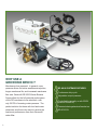
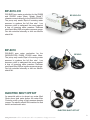
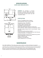
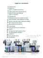
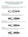
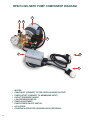
BP-6010
Bp-6010-CH
ESOK
Booster Pump
Owners Manual
w w w. g r o w on i x . c o m
www.growonix.com toll free 888.406.8521, office 818.510.0264, [email protected]
1
Why use a
GrowoniX BP6010 ?
Membranes love pressure! In general, more
pressure allows for better emembrane rejection,
longer membrane life, and increased membrane
flow rate. GrowoniX BP-6010 Series Booster
Pumps allow for the full potential performance
of the RO membrane to be acheived—with
only 35 PSI of incoming water pressure. The
perfect solution for those with low feed water
pressures, and those who want to receive the
maximum performance from their GrowoniX
water filter.
2
BP-6010 Systems FeatureS
Continuous duty cycle
Adjustable output pressure
Controllable manually or with ESOK
(electric shutoff kit)
Patented electrogalvanized bracket on
BP-6010-CH
BP-6010-CH
DOUBLES pure water production for the GX600
and GX1000 water filters. Splash Guard™
chassis connects directly to the GX600/GX1000.
The pump only needs 30psi of incoming water
pressure to produce the full flow rate! Low
pressure cutoff to safeguard the pump against
a loss of incoming water pressure. Stainless
steel liquid filled 300 psi system pressure gauge.
Can be controlled manually or with our electric
shutoff kit.
BP-6010
DOUBLES pure water production for the
GX600,GX1000, EX600, EX1000 water filters.
The pump only needs 30psi of incoming water
pressure to produce the full flow rate! Low
pressure cutoff to safeguard the pump against
a loss of incoming water pressure. Stainless
steel liquid filled 300 psi system pressure gauge.
Can be controlled manually or with our electric
shutoff kit.
BP-6010-CH
BP-6010
Electric Shut Off Kit
An essential add-on to almost any water filter!
Shuts down feed water before the water filter.
Controls on/off cycling of high pressure booster
pumps. The electric shutoff kit consists of a float
switch and solenoid valve.
Electric Shut Off Kit
www.growonix.com toll free 888.406.8521, office 818.510.0264, [email protected]
3
Safety
Read entire manual thoroughly
before installing this High pressure-boosting pump.
The Safety section of this User’s Manual outlines the carious safety headings used throughout
and this manual’s text and are enhanced and defined below:
NOTE:
INDICATES STATEMENTS THAT PROVIDE FURTHER INFORMATION & CLARIFICATION
CAUTION:
INDICATES STATEMENTS THAT ARE USED TO IDENTIFY CONDITIONS OR PRACTICES THAT
COULD RESULT IN EQUIPMENT OR OTHER PROPERTY DAMAGE.
WARNING:
INDICATES STATEMENTS THAT ARE USED TO IDENTIFY CONDITIONS OR PRACTICES THAT
COULD RESULT IN INJURY OR LOSS OF LIFE. FAILURE TO FOLLOW WARNINGS COULD
RESULT IN SERIOUS INJURY OR EVEN DEATH.
Plumbing
The membranes and high pressure pumps used on all GrowoniX water filters 600GPD and
greater (EX600, EX1000, GX600, GX1000) require a continuous flow of water with a minimum feed
pressure of 35psi, and which does not exceed 105°F.
The plumbing for the feed line for the RO is 3/4” MHT for quick setup and convenience. If the
water filter is to be installed in a permanent place, it is recomended to remove the garden hose fittings
and plumb with 3/4” SCH80 piping certified for drinking water.
The tubing for the waste line is 3/8” and and should be run to an open drain in a free and
unrestricted manner (no back pressure)
The tubing used for the permeate line is 3/8” and can be run to the holding tank or directly to
the point-of-use application with PVS fittings, or other FDA approved materials. This is so the material
being used does not dissolve into the permeate water. Be certain that all of the components of the feed
water are soluble at the concentrations attained in the system.
CAUTION:
ANY RESTRICTIONS OR BLOCKAGE IN THE DRAIN LINE CAN CAUSE BACK PRESSURE, WHICH
WILL INCREASE THE SYSTEMS OPERATING PRESSURE. THIS CAN RESULT IN DAMAGE TO
THE SYSTEM’S MEMBRANES AND COMPONENTS.
Electrical
The motor is a carbonator motor. It is available in 110/220 and 50/60 hertz 1 phase. Please ensure
that the electrical circuit supplying the system is compatible with the requirements of the BP-6010 Series
Delivery Pump. Each BP-6010 Series Delivery Pump is equipped with an 8” electrical cord.
NOTE:
WE RECOMMEND THAT A LICENSED ELECTRICIAN WIRE YOUR SYSTEM IN ACCORDANCE
WITH LOCAL AND NATIONAL ELECTRICAL CODES (NEC).
WARNING:
TO REDUCE THE RISK OF ELECTRICAL SHOCK, THE INCOMING POWER SUPPLY MUST
INCLUDE A PROTECTIVE EARTH GROUND.
4
MODELS
E
2
2
E
C
P
M
S
W
D
A
Pump
The pump is a low-lead brass rotary vane pump. Approx.
This pump is also available in stainless steel.
Adjustable
Follow these guidelines to ensure proper operation of the pump:
•
•
•
Max.
Model Switch
Range
Deadband
Pressure
The pump must
NEVER be
run dry.
Operating the
pump
without sufficient
feed
water will
Number
psig
(bar)
psig
(bar)
Type
psig
(bar)
damage the pump.
CXA-S1 NC
15-80 (1.0-5.5) 15-30 (1.0-2.1)
129 (8.9)
ALWAYS feedNC
the pump
filtered(2.1-6.9)
water. The pump
is (1.4-2.4)
susceptible to damage
sediment and
CXA-S2
30-100
20-35
179 from
(12.3)
debris.
CXA-S3 NC 35-150 (2.4-10.3) 30-40 (2.1-2.8)
204 (14.1)
CXA-R1
15-80
(1.0-5.5)pump,
If any damageNO
occurs to
your system’s
a re-build
kit may be available.
15-30
(1.0-2.1)
129 (8.9)
Contact your local dealer or distributor and inform them of your system’s model and pump
CXA-R2 NO
30-100 (2.1-6.9) 20-35 (1.4-2.4)
179 (12.3)
size.
CXA-R3 NO 35-150 (2.4-10.3) 30-40 (2.1-2.8)
204 (14.1)
Water Pump Pressure Switch
C
th
s
The low
pressure switch shuts off the system when the feed water pressure drops too low for the system
INSTALLATION/MOUNTING
to function properly. This prevents damage to the pump. The system restarts automatically when the
The
switchIfcan
be pipe
mounted
in any
position.
Do not
twist
the
pressure
is restored.
you notice
the pressure
fluctuating,
and the
system cycling
off and
on repeatedly,
turn the
system
off andinstalling.
ensure that proper
flow and pressure
available to the
system.
case
when
Use feed
a wrench
on thearepressure
connection
flats.
Water Pump Pressure Switch Adjustment
M
U
S
th
fi
re
in
a
g
MOTOR
M
TURN
CLOCKWISE
TO INCREASE
CUT-OUT
PRESSURE
POWER WITHOUT
SUPPLY AFFECTING
CUT-IN
LINE
MOTOR
TURN
CLOCKWISE
TO INCREASE
BOTH CUT-OUT
AND CUT-IN
PRESSURE
LINE
WIRING
The water
pump pressure
is adjusted
at the
factory toElectrical
cut out when
incoming
All wiring
must switch
conform
to the
National
Code
andpressure
local falls
below 10 psi, and cut in when incoming pressure reaches 25 psi. Pressure switch should not need
regulations. Do not install the control to handle loads in excess of
adjustment.
electrical
ratingswitch
shown
specifications
or instructions
as indicated
If for some
reason pressure
shouldin
fall out
of adjustment, follow
below. on
instructions inside control cover.
WIRING DIAGRAM
©Copyright 2006 Dwyer Instruments, Inc.
www.growonix.com toll free 888.406.8521, office 818.510.0264, [email protected]
Printed in U.S.A. 1
5
Bulletin IN-525A
Specifications
ssure Switch
Operating Instructions
Water Pump Pressure Switch
3-45/64
(94)
3-3/8
(85.5)
CAUTION: No lubrication or periodic
servicing is required. Mount the control
securely. Never exceed the electrical rating
for the switch. Use the control only with
Bulletin IN-525A
compatible medias.
A Water Pump Pressure Switch
SPECIFICATIONS
ons - Installation
and Operating Instructions
2-17/64
(57.6)
ONS
2-9/16
atible liquids and gases.(65)
als: Silicone, steel, and SS.
Limits: 140°F (60°C).
ts: See model chart.
ing: General purpose.
±5 psig (±0.3 bar).
SPST snap action (see model chart).
ngs: 20A @ 120 VAC, 12A @ 240 VAC, 9.6A @
ase), 8.6A @ 32 VDC, 3.1A @ 120 VDC, 1.6A @
Service: Compatible liquids and gases.
Wetted Materials: Silicone, steel, and SS.
Temperature Limits: 140°F
(60°C).
3-45/64
(94) chart.
Pressure Limits: See model
Enclosure Rating: General purpose.
Repeatability: ±5 psig (±0.3 bar).
Switch Type: SPST snap action (see model chart).
Electrical Ratings: 20A @ 120 VAC, 12A @ 240 VAC, 9.6A @
240 VAC (3 phase), 8.6A @ 32 VDC, 3.1A @ 120 VDC, 1.6A @
240 VDC.
3-3/8
Electrical Connections: Screw terminal.
(85.5)
Conduit Connection: 7/8˝ hole for 1/2˝ conduit hub (2 places).
Process Connection: 1/4˝ female NPT.
Mounting Orientation: Switch can be installed in any position.
Setpoint Adjustment: Internal screws.
Weight: 0.75 lb (0.34 kg).
Deadband: See
model chart.
2-17/64
Agency Approvals:
(57.6)CE, UL pending
nections: Screw terminal.
ection: 7/8˝ hole for 1/2˝ conduit hub (2 places).
ection: 1/4˝ female NPT.
entation: Switch can be installed in any position.
stment: Internal screws.
been
SPECIFICATIONS
be(0.34
kg).
e These
model chart.
Service: Compatible liquids and gases.
MAINTENANCE
vals:and
CE, UL pending.
ps
Wetted Materials: Silicone, steel, and SS.
Upon final installation
of the water
pump 140°F
pressure(60°C).
switch, no routine maintenance is required.
h easily
Temperature
Limits:
A periodic check of the system calibration is recommended. The pressure switchis not field serviceable
lubrication
periodic
servicing ifisrepair
required.
Mount
on, the
Pressure
Limits:
See (field
model
chart.
andor
should
be
returned
is needed
repair
should not be attempted and may void warranty).
curely. Never
exceed
the
electrical
rating
for
the
Be
sure
to
include
a
brief
description
of
the
problem
plus any relevant application notes.
on
andonly with compatible
Enclosure
Rating: General purpose.
controlContact
medias.
customer service to receive a return good authorization number before shipping.
design
Repeatability: ±5 psig (±0.3 bar).
Switch Type: SPST snap action (see model chart).
CE
Electrical
20A @ 120 VAC, 12A @ 240 VAC, 9.6A @
allation of the Series
CXA Water Ratings:
Pump Pressure
ine maintenance is240
required.
periodic
check
of @ 32 VDC, 3.1A @ 120 VDC, 1.6A @
VACA (3
phase),
8.6A
bration is recommended. The Series CXA is not
6
240 VDC.
e and should be returned
if repair is needed (field
Table of Contents
2
3
4
5
6
7
8
9
10
11
12
14
16
18
20
21
21
22
23
24
Introduction
Products
Safety | Plumbing | Electrical
Pump | water pump pressure switch
Specifications | Maintenance
Table of contents
Introduction
Information on Quick Connect fittings
BP6010 Delivery Pump Compnent Diagram
BP6010 CH Delivery Pump Compnent Diagram
Setup Instructions for EX
Setup Instructions for gX
Pump Tuning
Electric shutoff Kit Connection
XXXXXX
In-Tank Float Switch Installation
solenoid Manual Override
Warranty
Replacement parts
accesories
www.growonix.com toll free 888.406.8521, office 818.510.0264, [email protected]
7
Introduction
Our Mission
Durability, Reliability, Efficiency, Purity, and Conservation form the foundation on which we design
and build all of our products. Consistent and superior quality sets us apart from other manufacturers
and increases our value to you - our customer. Whether you are a hydroponics hobbyist, serious
enthusiast, or large-scale gardener, GrowoniX is committed to bringing you the best solution for
water purification systems.
What is Reverse Osmosis?
Reverse osmosis (RO) is a filtration method that removes many types of large molecules and ions
from solutions by applying pressure to the solution when it is on one side of a selective membrane.
This filtering process ensures that the solute (waste water) is contained within the pressurized
chamber while the pure solvent (RO water) is allowed to pass freely through the membrane.
Tuned for Growing - In Tune with Our Customers
Traditional RO systems have waste ratios of approximately 4:1, which means there are 4 gallons
of waste water produced for every 1 gallon of purified water. GrowoniX line of water filters achieve
waste ratios of 2:1 with the EX100 through GX400 and an astounding 1:1 ratio with the GX600 and
GX1000.
GrowoniX has created a complete product line that will address the needs of hydroponic operations
of all sizes. Our filters will significantly reduce your water use while dramatically increasing your yields.
THE TRADITIONAL WAY
takes 4 gallons of waste water to produce 1 gallon of pure water
PURE WATER
WASTE WATER
The
WASTE WATER
8
GrowoniX way
PURE WATER
Information on quick connect fittings
GrowoniX water filters use quick connect fittings
that allow for easy maintenance.
MAKE A CLEAN TUBE CUT
Cut the tube squarely and if using plastic tubing, ensure that the cut has not made the tube out of round.
Also ensure that the tube has a smooth outside diameter without any burrs or score marks
prior to inserting it into the fitting.
O-RING
COLLET
TUBING
INSERT TUBE INTO FITTING
Push the tubing through the collet and dual o-rings until it bottoms out against the tube stop.
The collet holds the tube in place and the dual o-rings provide a leak resistant seal.
TEST AND INSPECT
Push and pull the tubing toward and away from the fitting to ensure that it has been installed properly.
Test and inspect the installation for any leaks.
TUBE REMOVAL
Relieve pressure from the tubing and fitting. Push uniformly around the collet flange against the
fitting body while pulling the tubing away from the fitting to release it.
PUSH COLLET IN
PULL TUBE OUT
www.growonix.com toll free 888.406.8521, office 818.510.0264, [email protected]
9
Flow Rates
100GPD — 400GPD FILTER FLOW RATES
600
550
gallons per day
500
ex/GX400-hf, 77ºF
450
400
350
ex/GX400-hf, 60ºF
300
ex/GX400-hf, 50ºF
250
200
ex/GX200-hf, 77ºF
150
ex/GX200-hf, 60ºF
ex/GX200-hf, 50ºF
ex100-hf, 77ºF
ex100-hf, 60ºF
ex100-hf, 50ºF
100
50
0
40
45
50
55
60
65
70
75
80
water pressure (PSI) with or without pump
600GPD — 1000GPD FILTER FLOW RATES
2800
2600
ex/GX1000-hf, 77ºF
2400
gallons per day
2200
2000
ex/GX1000-hf, 60ºF
1800
1600
ex/GX600-hf, 77ºF
1400
ex/GX1000-hf, 50ºF
ex/GX600-hf, 60ºF
1200
1000
800
ex/GX600-hf, 50ºF
600
400
200
0
10
40
50
60
70
80
90
100 110 120 130 140 150 160 170 180
water pressure (PSI) with or without pump
Replacement Parts
MEMBRANE INDEX
Coconut Carbon Filter— “Green Block”
Premium coco carbon, produced using eco-friendly low
emissions processes
Coconut Carbon Filter—”White Block”
Economy coco carbon, same performance as Green
Block, for a little less money.
KDF85/Catalytyic Activated Carbon Filter
Premium carbon filter using the best activated carbon with
a bed of KDF85 media. There’s no better carbon available.
Sediment Spun
Spun poly sediment filters with huge dirt holding capacity.
Sediment Pleated
High flow sediment filters with ultra low pressure drop.
GXM Industrial Membranes
Highest flowing Dow sheet membranes on the planet, with
the lowest waste ratio.
GXM High Flow Cold Water Membranes
Highest flowing residential sized membranes.
Always 2:1 ratio.
Alkaline Inline
Inline filter adds calcium & magnesium to filtered water,
raises the Ph.
PRODUCT
TYPE
MSRP
SYSTEM
NOTES
Specialty filtration, accesories & Replacements
ALK-Inline
Alkaline
99.00
All RO systems
Raises ph, adds cal/mag mineral.
ALK-Cart
Alkaline
99.00
All RO systems
Raises ph, adds cal/mag mineral.
cartridge adds calcium & magnesium to filtered water,
raises the Ph.
RM-Inline
Re-Mineralize
67.00
All RO systems
Adds cal/mag minerals.
RM-CART
Re-Mineralize
67.00
All RO systems
Adds cal/mag minerals.
Remineralizing Inline
DI-Inline
De-Ionization
31.00
All RO systems
Removes remaining TDS after RO (aquarium, lab)
DI-Cart
De-Ionization
34.00
All RO systems
Removes remaining TDS after RO (aquarium, lab)
UV-1530
Ultraviolet
149.00
All RO, Scrubber
systems, tank
storage
Kills 99.9% bacteria
UV-6010
Ultraviolet
215.00
All RO, Scrubber
systems, tank
storage
Kills 99.9% bacteria / viruses
Kills 99.9% bacteria and viruses.
UV-LB
Ultraviolet
443.00
All RO, Scrubber
systems, tank
storage
Kills 99.9% bacteria / viruses
DI Inline
UV-XL
Ultraviolet
538.00
All RO, Scrubber
systems, tank
storage
Kills 99.9% bacteria / viruses
Alkaline Cartridge
Inline filter adds calcium & magnesium to filtered water,
Remineralizing Cartridge
cartridge adds calcium & magnesium to filtered water,
UV Sterilization
De-Ionization filter removes last bit of PPM.
Product Type
Application / System
MSRP
Capacity
Notes
Replacements for all water filters 400 GPD and under
SF-2510-PL
Sediment Pleated
EX100/200/400/400-Tall, GX200/300/400, Mini Scrub
14.50
Depends on feed water piping/supply
Stock on GX Series
SF-2510-SP
Sediment Spun
EX100/200/400/400-Tall, GX200/300/400, Mini Scrub
10.75
Depends on feed water piping/supply
Stock on EX Series
Stock on EX Series
CF-2510-CC
Economy Coco Carbon
EX100/200/400/400-Tall, GX200/300/400, Mini Scrub
12.00
7,500 Gallons Total
2,500 Gallons RO Water
CF-2510-GB
Green Carbon
EX100/200/400/400-Tall, GX200/300/400, Mini Scrub
16.50
7,500 Gallons Total
2,500 Gallons RO Water,
Stock on GX Series
CF-2510-KDF
Premium Carbon
EX100/200/400/400-Tall, GX200/300/400, Mini Scrub
39.00
8,000 Gallons Total 2,700 Gallons RO Water
Must for well water and chloramine removal
GXM-100
Standard Membrane
100+ GPD membrane for EX100
83.00
Depends on feed water quality
Fits most other RO systems
GXM-200-HF
High Flow Cold Water
Membrane
200+ GPD High Flow Cold Water Membrane for EX100/200/400/400-Tall,
GX200/300/400
99.00
Depends on feed water quality
Fits most other RO systems
BP-1530
Booster Pump
Booster pump for all RO systems 600 GPD and under.
227.00
12,000 Hrs brush life
Booster pump for all RO systems 600 GPD and under
Replacements for EX400HF-Tall and SlimScrub
SF-2520-SP
Sediment Spun
EX400-tall, Slim Scrub
10.75
Depends on feed water piping/supply
CF-2520-CC
Economy Coco Carbon
EX400-tall, Slim Scrub
24.00
16,000 Gallons Total
5,300 Gallons RO Water
CF-2520-KDF
Premium Carbon
EX400-tall, Slim Scrub
71.00
17,000 Gallons Total
5,700 Gallons RO Water
Must for well water and chloramine removal
CF-4520-KDF
Premium Carbon
EX600/1000-Tall, XL Scrub
127.00
34,000 Gallons Total
17,000 Gallons RO
Must for well water and chloramine removal
www.growonix.com toll free 888.406.8521, office 818.510.0264, [email protected]
11
BP6010 Delivery Pump Component Diagram
1
3 2
5
6
7
8
9
1.
2.
3.
4.
5.
6.
7.
8.
9.
12
Motor
Pump Inlet (connect to pre filter housing output)
Pump Outlet (connect to membrane input)
Outlet Pressure Gauge
Low Pressure Switch
Pump Adjustment
Pump Power On/Off Switch
ac in cord
piggyback cord for solenoid valve (Optional)
BP6010 CH Delivery Pump Component Diagram
4
3 2
1
6
5
7
8
9
1.
2.
3.
4.
5.
6.
7.
8.
9.
Motor
Pump Inlet (connect to pre filter housing output)
Pump Outlet (connect to membrane input)
Outlet Pressure Gauge
Low Pressure Switch
Pump Adjustment
Pump Power On/Off Switch
ac in cord
piggyback cord for solenoid valve (Optional)
www.growonix.com toll free 888.406.8521, office 818.510.0264, [email protected]
13
Setup Instructions For EX
1
2
Slide locking clip off of carbon filter
output fitting and remove the short
length of 1/2” tubing feeding the
membrane input.
3
Insert supplied 1/2” tubing into carbon
filter output. Install locking cip.
4
Cut tubing to appropriate length (ensure
no kinks or flow restrictions) and insert into
the 1/2” pump input. Install locking clip.
5
Insert supplied 3/8” tubing into pump
high pressure output. Install locking cip.
6
B
Cut tubing to appropriate length (ensure
no kinks or flow restrictions) and install
the 1/2” x 3/8” stem reducer onto
tubing. Insert the stem reducer into
the 1/2” membrane input fitting. Install
locking clip.
14
A
A) From output of carbon filter housing
to pump input.
B) From high pressur pump output to
input side of membrane housing.
7
Reconnect all locking clips as shown
www.growonix.com toll free 888.406.8521, office 818.510.0264, [email protected]
15
Setup Instructions For GX
1
2
Slide locking clip off of carbon filter
output fitting and remove the short
length of 1/2” tubing feeding the
membrane input.
3
Remove caster nut and washer
4
Attach BP-6010-CH chassis to
GX600/1000 housing. Replace caster
nut and washer and tighten.
5
6
Cut tubing to appropriate length
(ensure no kinks or flow restrictions)
and insert into the 1/2” pump input.
Install locking clip.
16
Insert supplied 1/2” tubing into carbon
filter output. Install locking cip.
Insert supplied 3/8” tubing into pump
high pressure output. Install locking cip.
7
A
8
B
Slide locking clip off of prefilter output
fitting.
Cut tubing to appropriate length (ensure
no kinks or flow restrictions) and install
the 1/2” x 3/8” stem reducer onto
tubing. Insert the stem reducer into
the 1/2” membrane input fitting. Install
locking clip.
9
Reconnect all locking clips as shown
www.growonix.com toll free 888.406.8521, office 818.510.0264, [email protected]
17
PUMP TUNING
TUNING THE BP-6010 PUMP
1. The bypass valve, located on the input side of the pump can be used to regulate
pump output pressure. It is adjustable with a flat head screwdriver.
2. While referencing pump pressure gauge,
turn screw clockwise to increase system pressure.
3. Turn screw counterclockwise to decrease system pressure.
4. Set system pressure at maximum 150 psi. Running the system at higher pressure
could result in failure of fittings, and possible injury.
18
PUMP TUNING
TUNING THE BP-6010-CH PUMP
1. The bypass valve, located on the input side of the pump can be used to regulate
pump output pressure. It is adjustable with a flat head screwdriver.
On the BP-6010-CH, an access hole located on the rear cover allows for pump
adjustment. Depending on pump/motor combination, it may be necessary to
remove access hole rubber grommet to allow more room for adjustment.
2. While referencing pump pressure gauge,
turn screw clockwise to increase system pressure.
3. Turn screw counterclockwise to decrease system pressure.
4. Set system pressure at maximum 150 psi. Running the system at higher pressure
could result in failure of fittings, and possible injury.
www.growonix.com toll free 888.406.8521, office 818.510.0264, [email protected]
19
Electric Shut Off Kit component diagram
3
1
direction
of flow
5
2
1.
2.
3.
4.
5.
Solenoid valve
Float Switch
Float switch piggyback cord
Solenoid valve manual override switch
Solenoid valve direction of flow
Solenoid Manual Override switch
normal
operation
manual
override
4
20
4
Electric Shut Off Kit connection
1
2
3
Disconect pump and all components from electrical supply,
and Turn off feed water supply before connecting the ESOK.
1. Install float switch in tank. (refer to page 21)
2. Attach float switch piggyback cord to male plug end from pump control box.
• The float switch will now govern whether current will flow to the pump control box or not. • Float ball facing up=current does not flow (pump off).
• Float ball facing downwards-current flows (pump on)
3. Plug solenoid valve into female plug end extending from pump control box (3).
• When pump control switch is “ON”, current will flow to the solenoid valve,
and the valve will open.
•If being used in conunction with the float switch, current will not flow to pump control box or solenoid valve until float ball faces downward.
Solenoid Valve
4. Install solenoid valve on the input of the GX600/GX1000, making sure valve is installed in the
correct direction of flow. (see arrow stamped on valve housing).
5. Make sure override switch is in the Normal Operation position (see: page 18).
6. Turn on feed water supply and check for leaks in solenoid water connections.
7. Turn on Booster Pump manualy or with Float Switch.
8. Adjust output pressure (see page 16-17)
www.growonix.com toll free 888.406.8521, office 818.510.0264, [email protected]
21
Electric Shut Off Kit connection
1
3
2
Disconect pump and all components from electrical supply,
and Turn off feed water supply before connecting the ESOK.
1. Install float switch in tank. (refer to page 21)
2. Attach float switch piggyback cord to male plug end from pump control box.
• The float switch will now govern whether current will flow to the pump control box or not. • Float ball facing up=current does not flow (pump off).
• Float ball facing downwards-current flows (pump on)
3. Plug solenoid valve into female plug end extending from pump control box (3).
• When pump control switch is “ON”, current will flow to the solenoid valve,
and the valve will open.
•If being used in conunction with the float switch, current will not flow to pump control box or solenoid valve until float ball faces downward.
Solenoid Valve
22
4. Install solenoid valve on the input of the GX600/GX1000, making sure valve is installed in the
correct direction of flow. (see arrow stamped on valve housing).
5. Make sure override switch is in the Normal Operation position (see: page 18).
6. Turn on feed water supply and check for leaks in solenoid water connections.
7. Turn on Booster Pump manualy or with Float Switch.
8. Adjust output pressure (see page 16-17)
Solenoid plumbing connection
It's recomended to remove garden hose fittings from water filter input
and attach supplied SCH80 PVC as shown below.
Solenoid installed on EX and GX Series Filter
www.growonix.com toll free 888.406.8521, office 818.510.0264, [email protected]
23
In-Tank Float Switch Installation
Figure 2
Figure 1
Tether
Length
Pumping
Range
4"
8"
5"
9"
6"
10"
7"
11"
8"
12"
9"
13"
10"
14"
11"
15"
12"
16"
13
17"
14"
18"
15"
19"
16"
20"
17"
21"
18"
22"
Normally Closed Float switches are closed
while hanging “down” and will open on a rising liquid level.
Typically used for “filling tank” applications.
1. Determine desired cord tether length . See Figure 2.
2. Attach the Pipe Clamp at the desired location. See Figure 1.
Adjust the tether length to achieve the desired pumping range.
Use Figure 2 as a guide and test system by filling tank and cycling the system
to achieve actual desired pumping range.
3. Tighten the clamp
4. Electrical outlet must not be located in pump chamber.
Electrical outlet voltage, piggyback plug voltage, and pump voltage must match.
5. Insert switch’s piggyback plug into outlet.
6. Plug pump into piggyback plug and check the system
by allowing the system to cycle to insure proper operation.
WarninG:
Turn off all power when installing or adjusting unit.
Failure to turn off all power could result in serious injury or death!
Warning: End user to provide overcurrent protection rated at 240VAC
minimum, 15 Amps maximum.
Read instructions thoroughly. Check local codes and install to meet requirements.
24
GrowoniX GX 600/1000 Accesories
GXM Industrial Membranes
Electric Shut Off Kit
DDP-6
BP-6010
BP-6010-CH
Flow Boxes
An essential add-on to almost any
water filter! Shuts down feed water
before the water filter. Controls on/
off cycling of high pressure booster
pumps. The electric shutoff kit
consists of a float switch and solenoid
valve. Mount the float switch in your
water tank or nutrient storage tank.
Install the solenoid valve on the front
end of your water filter. When the tank
level decreases to the desired amount,
the float switch opens the solenoid
valve, the booster pump (if installed)
powers on, and the water system
begins refilling the storage tank.
The DDP-6 is the ultimate water
delivery pump. With a flow rate
of 6.5 GPM, the DDP-6 can move
water from on end of the garden
to the other in a flash. Integral as
a feed pump and return pump for
GrowoniX smaller nutrient top feed
systems, the DDP-6 can withstand
the most rigorous of duties. Built in
high pressure cutoff allows for easy
use with solenoid valves, manual
shutoff valves, watering wands, hose
sprayers, or faucets
DOUBLES pure water production for
the EX600,EX1000, EX600, EX1000
water filters. The pump only needs
30psi of incoming water pressure
to produce the full flow rate! Low
pressure cutoff to safeguard the
pump against a loss of incoming water
pressure. Stainless steel liquid filled
300 psi system pressure gauge. Can
be controlled manually or with our
electric shutoff kit.
DOUBLES pure water production for
the GX600 and GX1000 water filters.
Splash Guard™ chassis connects
directly to the GX600/GX1000. The
pump only needs 30psi of incoming
water pressure to produce the full flow
rate! Low pressure cutoff to safeguard
the pump against a loss of incoming
water pressure. Stainless steel liquid
filled 300 psi system pressure gauge.
Can be controlled manually or with our
electric shutoff kit.
GrowoniX FlowBox is a componential
add-on to any GX600/1000 or
EX600/1000 that utilizes a BP Series
booster pump. Equipped with highly
accurate liquid flow meters, the
FlowBox allows for custom tuning and
fine-tuning of the system ratio. Run
your system at any ratio from 3:1 to
1:1— whenever you want. System
ratios change throughout the year as
the weather temperatures change.
Keep a perfect 1:1 all year round with
a FlowBox. Flush the system with
a simple twist of the stainless steel
needle valve. Allows for removal of
the standard drain/flush assembly.
Mounts atop the GX series chassis for
easy viewing and adjusting. Easy wall
mounting as well.
These Dow sheet, American made
membranes are the industries most
reliable and highest performing
reverse osmosis elements in the world.
Advanced
membrane
technology
and manufacturing processes ensure
superior quality and unmatchable
performance. Ultra low energy design
delivers high flow and high rejection at
only 80psi.
A must for cold water sources.
Always at an industry leading 1:1 ratio.
Flow Rate: 600 gpd high flow
membrane
Membrane replacement for GX600,
EX600, EX600-T
UV Sterilization
Flow Rate:1000 gpd high flow
membrane
Membrane replacement for GX1000
EX1000, EX1000-T
Stainless steel ultraviolet filtration to
remove 99.9% of micro- organisms in
your water supply. A must for well water
treatment, whole house filter systems,
or anytime water will be stored.
coconut carbon / green block
Green
Coco:
NFS61
Listed
Greencarbon. High flow with a low
carbon footprint. Superior chlorine
removal..
Sediment Spun
Spun polypropylene: A true multistaged depth filter utilizing separate
layers of micron filtration. Constructed
spun polypropylene, these filters offer
superior dirt holding capacity at an
extremely economic price. Great filter
for changing frequently, especially in
well water applications, or with use in
GrowoniX scrubbers.
Sediment Pleated
4.5”x9.75” Spun | 16000 gallons
High flow pleated Sediment filter: This
is a washable, reusable, and durable
sediment filter with very low pressure
drop. Bacteria and chemical resistant.
Great for high flow applications and
extended time between fitler changes.
Comes standard in most GrowoniX
water filters.
4.5”x9.75” | 16000 gallons
KDF85/Catalytyic Carbon Filter
www.growonix.com toll free 888.406.8521, office 818.510.0264, [email protected]
KDF/CAT.
Bacteriostatic
media
controls growth of microorganisms.
Good for water soluble metals removal,
chlorine, chloramine, and scale. Highly
reactive catalytic carbon, extremely
porous and long lasting.
4.5”x9.75” | 16000 gallons
25
GrowoniX Reverse Osmosis System Warranty
For a period of one year from the date of original purchase, we will replace or repair any part of the GrowoniX
reverse osmosis water system that we find to be defective in operation du e to faulty materials or workmanship
with the EXception of the replaceable filters and membranes.
GENERAL CONDITIONS
Damage to any part of this reverse osmosis system because of misuse; misapplication; negligence; alteration;
accident; installation; or operation contrary to our instructions, incompatibility with accessories not installed
by GrowoniX, or damage caused by freezing, flood, fire, or Act of God, is not covered by this warranty. In all
such cases, regular charges will apply. This limited warranty does not include service to diagnose a claimed
malfunction in this unit. This warranty is void if the claimer is not the original purchaser of the unit or if the unit
is not operated under normal municipal water or well water conditions.
GrowoniX assumes no liability in connection with this reverse osmosis system. GrowoniX assumes no liability
for any damages incurred through the use of this product. It is the responsibility of the end user to gauge the
safe use of this product in the environment where it is applied. We do not authorize any person or representative
to assume for us any other obligations on the sale of this reverse osmosis system. The information given out
in the manual we believe to be true, but are offered to you in good faith without guarantee because each
application of this product is different and beyond our control.
THE FOLLOWING STANDARD OPERATING CONDITIONS FOR RESIDENTIAL/COMMERCIAL REVERSE
OSMOSIS SYSTEMS MUST BE MET FOR WARRANTY TO BE VALID.
Standard System
Water Pressure
pH Range
Maximum TDS
Water Temp
40-80 psi
2-11
2000 ppm
40-100 F
GrowoniX Return Policy
Merchandise Return Details and Procedure:
If any merchandise was defective —we will refund the full purchase price upon receiving and reviewing the
merchandise returned in undamaged condition.
RMA Number:
You must first obtain a Return Merchandise Authorization (RMA) number from GrowoniX.com. Any products
sent to GrowoniX without an RMA number will not receive a refund and may be returned to the sender at their
expense.
All refund amounts will be based on the manufacturer’s warranty and GrowoniX return policy. Refunds will be
issued back using the payment method you used when you placed your order. Refunds take up to 3-5 business
days to process once we receive the return.
Packaging:
Please kindly re-pack the product in its original box, or a box of equivalent strength. The unit should be packed
in the same manner as it came to prevent damage in shipping. Please return everything that was in the original
box, including any free items if applicable. Be sure to drain out all water from wet systems and parts and wrap
them in plastic bags before packing.
Return To:
We will provide you with an GrowoniX warehouse address for return merchandise when we issue the RMA number.
26