1
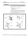
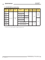
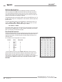
®
®
A-GAGE
MINI-ARRAY
Measuring Light Screen System (MAC Series Controllers)
Instruction Manual
Features
Controller Models MAC-1, MACN-1, MACP-1,
MACV-1, MACI-1, MAC16N-1, MAC16P-1
(See Section 1.1 for additional, model-specific features)
• Measuring Light Screen system for inspection and profiling
applications.
• Modular system with compact controller and a variety of BMEL/
BMRL series MINI-ARRAY emitters and receivers.
• Sensors available with either 9.5 mm (3/8") or 19.1 mm (3/4")
beam spacing and with array lengths from 6" to 4'
(in 6" increments), plus 5' and 6' models.
• Controller is programmable for any one or two of ten
measurement modes (depending on model) and any one of four
scanning modes, using a computer running Windows®
the Banner-supplied software
• Software is also supplied for display of error analysis (via
controller self-diagnostics) and for sensor alignment.
• System status, including alignment, is displayed via LED
indicators on the controller and on the receivers.
• Controller may be programmed for blanking to ignore activity in
one or two fields along the length of the array.
• Programmable hysteresis at the high and/or low limit of each
measurement area provides smoothing of output response;
also programmable for number of consecutive scans before an
output update.
• Separate gate input (e.g., from a presence sensor) allows control
of scan initiation.
• Supports serial communication with a computer or PLC via RS-
232C interface; enables a computer or PLC to process scan data
and/or initiate scans; serial data may be either ASCII or binary.
!
WARNING . . .
Not To Be Used for Personnel Protection
Never use these products as sensing devices for personnel protection. Doing so could lead to serious injury or death.
These sensors do NOT include the self-checking redundant circuitry necessary to allow their use in personnel safety applications. A
sensor failure or malfunction can cause either an energized or de-energized sensor output condition. Consult your current Banner
Safety Products which meet OSHA, ANSI and IEC standards for personnel protection.
Printed in USA
P/N 43298 rev. F
MINI-ARRAY®
Contents
Instruction Manual
Table of Contents
1. System Overview . . . . . . . . . . . . . . . . . . . . . . . . . . . . . . . . . . . . . . . . page 3
1.1 System Features . . . . . . . . . . . . . . . . . . . . . . . . . . . . . . . . . . . . . . . . . . . . . . . . 4
1.2 System Components . . . . . . . . . . . . . . . . . . . . . . . . . . . . . . . . . . . . . . . . . . . . . 7
2. Specifications . . . . . . . . . . . . . . . . . . . . . . . . . . . . . . . . . . . . . . . . . . page 9
2.1 Emitter and Receiver Specifications . . . . . . . . . . . . . . . . . . . . . . . . . . . . . . . . . 9
2.2 Emitter and Receiver Dimensions . . . . . . . . . . . . . . . . . . . . . . . . . . . . . . . . . . 10
2.3 Controller Specifications . . . . . . . . . . . . . . . . . . . . . . . . . . . . . . . . . . . . . . . . . 11
2.4 Controller Dimensions . . . . . . . . . . . . . . . . . . . . . . . . . . . . . . . . . . . . . . . . . . . 12
3. Installation and Mechanical Alignment . . . . . . . . . . . . . . . . . . . . . . . . page 13
3.1 Emitter and Receiver Mounting . . . . . . . . . . . . . . . . . . . . . . . . . . . . . . . . . . . . 13
3.2 Controller Mounting . . . . . . . . . . . . . . . . . . . . . . . . . . . . . . . . . . . . . . . . . . . . . 14
3.3 Emitter and Receiver Hookups . . . . . . . . . . . . . . . . . . . . . . . . . . . . . . . . . . . . . 14
3.4 Controller Wiring and Output Hookups . . . . . . . . . . . . . . . . . . . . . . . . . . . . . . 15
3.5 System Power . . . . . . . . . . . . . . . . . . . . . . . . . . . . . . . . . . . . . . . . . . . . . . . . . 18
3.6 Gate . . . . . . . . . . . . . . . . . . . . . . . . . . . . . . . . . . . . . . . . . . . . . . . . . . . . . . . . . 18
3.7 Serial Communication . . . . . . . . . . . . . . . . . . . . . . . . . . . . . . . . . . . . . . . . . . . 18
4. Software Installation . . . . . . . . . . . . . . . . . . . . . . . . . . . . . . . . . . . . . page 19
5. Controller Configuration . . . . . . . . . . . . . . . . . . . . . . . . . . . . . . . . . . page 20
5.1 Communications Setup . . . . . . . . . . . . . . . . . . . . . . . . . . . . . . . . . . . . . . . . . . 20
5.2 Alignment Analysis . . . . . . . . . . . . . . . . . . . . . . . . . . . . . . . . . . . . . . . . . . . . . 20
5.3 Alignment . . . . . . . . . . . . . . . . . . . . . . . . . . . . . . . . . . . . . . . . . . . . . . . . . . . . . 21
5.4 Parameter Setup Files (PSFs) . . . . . . . . . . . . . . . . . . . . . . . . . . . . . . . . . . . . . 22
5.5 Creating New Parameter Setup Files (PSFs) . . . . . . . . . . . . . . . . . . . . . . . . . . 25
5.5.1 Analysis Mode Assignment . . . . . . . . . . . . . . . . . . . . . . . . . . . . . . . . . . 25
5.5.2 Output Programming . . . . . . . . . . . . . . . . . . . . . . . . . . . . . . . . . . . . . . . 25
5.5.3 Analysis Mode Selection . . . . . . . . . . . . . . . . . . . . . . . . . . . . . . . . . . . . 28
5.5.4 Blanking Specifications . . . . . . . . . . . . . . . . . . . . . . . . . . . . . . . . . . . . . 29
5.5.5 Scanning Methods . . . . . . . . . . . . . . . . . . . . . . . . . . . . . . . . . . . . . . . . . 31
5.5.6 Control Mode Selection . . . . . . . . . . . . . . . . . . . . . . . . . . . . . . . . . . . . . 32
5.6 Serial Communication . . . . . . . . . . . . . . . . . . . . . . . . . . . . . . . . . . . . . . . . . . . 32
5.7 PSF Assignment and Storage . . . . . . . . . . . . . . . . . . . . . . . . . . . . . . . . . . . . . . 33
6. System Operation . . . . . . . . . . . . . . . . . . . . . . . . . . . . . . . . . . . . . . . page 35
6.1 Sensor Operating Status Indicators . . . . . . . . . . . . . . . . . . . . . . . . . . . . . . . . . 35
6.2 Controller Operating Status Indicators . . . . . . . . . . . . . . . . . . . . . . . . . . . . . . . 36
6.3 Diagnostics Program . . . . . . . . . . . . . . . . . . . . . . . . . . . . . . . . . . . . . . . . . . . . 37
Appendix . . . . . . . . . . . . . . . . . . . . . . . . . . . . . . . . . . . . . . . . . . . . page 39
Host Mode Command . . . . . . . . . . . . . . . . . . . . . . . . . . . . . . . . . . . . . . . . . . . . . . . . . . . . 39
Serial Data Format . . . . . . . . . . . . . . . . . . . . . . . . . . . . . . . . . . . . . . . . . . . . . . . . . . . . . . 39
Banner Engineering Corp. • Minneapolis, MN U.S.A.
www.bannerengineering.com • Tel: 763.544.3164
MINI-ARRAY®
System Overview
Instruction Manual
1. System Overview
The Banner A-GAGE® MINI-ARRAY measuring light screen is ideal for applications
such as on-the-fly product sizing and profiling, edge-guiding and center-guiding, loop
tensioning control, hole detection, parts counting, die ejection verification, and similar
uses.
A typical MINI-ARRAY System consists of five components:
• a Controller module,
• an emitter and corresponding receiver, and
• two interconnecting cables.
Sensors are available in array lengths from 6" to 4' (in 6" increments), plus 5' and 6'
array models, as listed on page 7. Sensors are available with either 9.5 mm (3/8") or
19.1 mm (3/4") beam spacing, which translates to either 32 or 16 beams per foot of
array length. Sensors with 3/8" beam spacing have a sensing range of up to 6 m (20').
Sensors with 3/4" beam spacing have a sensing range of up to 17 m (55'); 5' and 6'
arrays have shorter range (see Specifications).
Paint Booth
Profiling
Box Profiling
Inspection Applications
Edge Guiding
Figure 1-1. Typical MINI-ARRAY Applications
Banner Engineering Corp. • Minneapolis, MN U.S.A.
www.bannerengineering.com • Tel: 763.544.3164
P/N 43298 rev. E 3
MINI-ARRAY®
System Overview
Instruction Manual
1.1 System Features
Built-in features simplify the operation of the A-GAGE MINI-ARRAY system.
Programmable beam blanking accommodates machine components or other fixtures
that must remain in or move through the light screen. Blanking is set by using the
included configuration software. See Section 5.5.4 for more information.
Built-in diagnostic programming and easy-to-see indicators on the sensors and the
control module make alignment and troubleshooting easy (Figure 1-2). The emitter
has a red LED that signals proper operation. The receiver has three bright LEDs:green
signals that the sensors are properly aligned; yellow signals marginal alignment; and
red signals misalignment or a blocked condition. The control module has seven status
indicators: 5 red LEDs signal when outputs are conducting (see Section 3 for more
information), Alarm output conducting, and gate signal received; a green LED signals
that the sensors are properly aligned. DIAG 1, 2, and 3 LEDs indicate system status. A
key to the diagnostics codes is printed on the side of the control module for simplified
troubleshooting (see Section 6.3).
The MINI-ARRAY System provides a wide selection of sensing and output options,
including: measurement (“scan analysis”) modes and scanning methods that can
determine the target object’s location, overall size, total height or total width. Scanning
may be continuous or controlled by a host process controller or a gate sensor. Some
models (MAC1, MACP, MACN) support RS-485, where up to 15 systems may be
networked.
Emitter
Receiver
DIN-Rail-Mountable Control Module
Red Discrete
Output #1 LED
Red Alarm
(Discrete Output #2) LED
MINI-ARRAY
CONTROLLER
MAC-1
RS-232
15 14 13 12 11 10
OUT 1
DIAG 1
ALARM
DIAG 2
GATE
DIAG 3
ALIGN
9
8
T/R
7
6
5
3
2
T/R DRN COM +12V
30V + + 500mA WH BK
150mA RS485 10-30V DC Max
GATE
Max.
OUT 1
ALARM
1
F1
BU BR
5 Wires
L2 L1
16-30V DC
1.2A Max.
RS-232
Red Gate LED
EMTR
Green Align LED
4
15 14 13 12 11 10
9
2 - TX
3 - RX
5 - COM
RCVR
8
7
6
5
4
POWER
3 2 1
Red
Operational
LED
Green Alignment LED
Red Blocked LED
Yellow Marginal
Alignment LED
RS-232 Port
Figure 1-2. A-GAGE MINI-ARRAY System features
Banner Engineering Corp. • Minneapolis, MN U.S.A.
4 P/N 43298 rev. E
www.bannerengineering.com • Tel: 763.544.3164
MINI-ARRAY®
System Overview
Instruction Manual
1.1.1 Model-Specific Features
Models MAC-1, MACN-1, and MACP-1
• Supports serial communication with a host computer or PLC via RS-232 or RS-485
interface; enables a computer or PLC to process scan data and/or initiate scans;
serial data may be either ASCII or binary.
• Up to 15 controllers may be assigned separate IDs and placed on RS-485 party line.
• MAC-1: Two outputs: one reed relay and one NPN transistor output; either output
may be inverted (i.e., programmed for normally open or normally closed).
• MACN-1 and MACP-1: Two discrete open-collector PNP (current sourcing) or NPN
(current sinking) transistor outputs, depending on model.
Models MACV-1 and MACI-1
• Analog output null and span can be adjusted via PC interface and supplied software.
• Analog output signal can have either a rising or falling slope.
• Analog outputs will automatically adjust to sensor length.
• Discrete output is an open-collector NPN (current sinking) that can be used as an
alarm, a trigger, or used with an Analysis Mode Selection (output capable of being
inverted in Analysis Mode).
• MACV-1: Two linear sourcing analog voltage outputs (0 to 10 volts) and one NPN
transistor output.
• MACI-1: Two linear sinking analog current outputs (4 to 20 mA) and one NPN
transistor output.
Models MAC16N-1 and MAC16P-1
• Two additional measurement modes:
TRN mode counts the number of clear-to-blocked and blocked-to-clear transitions;
SEG mode partitions the array into up to 16 regions.
• Controller has flexible blanking capabilities with unlimited blanking conditions.
Blanking may be set automatically (Auto Blanking) or specified using the supplied PC
software.
• MAC16N-1: 16 discrete open-collector NPN (current sinking) transistor outputs.
• MAC16P-1: 16 discrete open-collector PNP (current sourcing) transistor outputs.
Banner Engineering Corp. • Minneapolis, MN U.S.A.
www.bannerengineering.com • Tel: 763.544.3164
P/N 43298 rev. E 5
System Overview
MINI-ARRAY®
Instruction Manual
1.1.2 Sensing Response
Sensing response is a function of the number of beams interrogated (i.e., steps) per
scan of the array. The time per step is 55 µs (0.000055 seconds). As a result, dense
arrays (i.e., 3/8" beam spacing) yield the highest sensing resolution, while arrays with
wider (3/4") beam spacing offer faster sensing response.
1.1.4 Supplied System Software
The supplied software program, used to configure each System control module, may
be run on any PC running Windows®
The menu-driven
program walks the user through the many scanning and output options. After the
desired options are selected, the user can save the combination of selections in a
Parameter Setup File (PSF), and store it in the control module’s non-volatile memory.
Any number of PSFs may be stored in the computer and recalled as needed.
The software also provides alignment and diagnostics routines. An Alignment screen
displays the individual status of each beam in the light screen, as well as the total
number of beams in the System, and totals of beams blocked, made, and blanked.
Built-in system diagnostics can be used to assess emitter and receiver hardware
errors.
Banner Engineering Corp. • Minneapolis, MN U.S.A.
6 P/N 43298 rev. E
www.bannerengineering.com • Tel: 763.544.3164
MINI-ARRAY®
System Overview
Instruction Manual
1.2 System Components
Emitter
Receiver
1.2.1 Emitter and Receiver Models
19.1 mm (3/4") beam spacing – 16 beams/foot
Emitter / Receiver
Models
Array Length
Total
Beams
BMEL616A / BMRL616A
133 mm (5.25")
8
BMEL1216A / BMRL1216A
286 mm (11.25")
16
BMEL1816A / BMRL1816A
438 mm (17.25")
24
BMEL2416A / BMRL2416A
591 mm (23.25")
32
BMEL3016A / BMRL3016A
743 mm (29.25")
40
BMEL3616A / BMRL3616A
895 mm (35.25")
48
BMEL4216A / BMRL4216A
1048 mm (41.25")
56
BMEL4816A / BMRL4816A
1200 mm (47.25")
64
BMEL6016A / BMRL6016A
1505 mm (59.25")
80
BMEL7216A / BMRL7216A
1810 mm (71.25")
96
User-Supplied PC
Configure and monitor the System
with the supplied software and
a PC-compatible computer (see
Section 1.1.4).
DIN-Rail-Mountable
Control Module
9.5 mm (3/8") beam spacing – 32 beams/foot
BMEL632A / BMRL632A
143 mm (5.62")
16
BMEL1232A / BMRL1232A
295 mm (11.62")
32
BMEL1832A / BMRL1832A
448 mm (17.62")
48
BMEL2432A / BMRL2432A
600 mm (23.62")
64
BMEL3032A / BMRL3032A
752 mm (29.62")
80
2 required per system
BMEL3632A / BMRL3632A
905 mm (35.62")
96
Model
BMEL4232A / BMRL4232A
1057 mm (41.62")
112
BMEL4832A / BMRL4832A
1210 mm (47.62")
128
BMEL6032A /BMRL6032A
1514 mm (59.62")
BMEL7232A / BMRL7232A
1819 mm (71.62")
Quick-Disconnect
Cables
Figure 1-3. MINI-ARRAY system components
1.2.2 Controller-to-Sensor Cables
Length
QDC-515C
4.6 m (15')
QDC-525C
7.6 m (25') QDC-550C
15.2 m (50')
160
MAQDC-575C
22.7 m (75') 192
MAQDC-5100C
30.3 m (100') MAQDC-5125C
37.9 m (125') MAQDC-5150C
45.5 m (150')
QD Connector
5-pin Mini-style
straight
Banner Engineering Corp. • Minneapolis, MN U.S.A.
www.bannerengineering.com • Tel: 763.544.3164
P/N 43298 rev. E 7
MINI-ARRAY®
System Overview
Instruction Manual
1.2.3 MINI-ARRAY MAC Series Controller Models
Controller
Model
Supply
Voltage
Inputs
MAC-1
Output 1
Scan
Analysis
Modes*
Output 2
PSF
Parameter
Diskette
Discrete Reed Relay
Discrete NPN
MACN-1
Discrete NPN
MACP-1
Discrete PNP
MACV-1
MACI-1
Serial
Output
16 to 30V dc
1 Sensor Pair
1 Gate
(2) Analog
0 to 10V dc Sourcing
(2) Analog
4 to 20 mA Sinking
Discrete PNP
RS-232
and
RS-485
8
43989
Discrete NPN
MAC16N-1
16 Discrete NPN Outputs
MAC16P-1
16 Discrete PNP Outputs
RS-232
10
59114
Dimensions for all MAC Series Controllers listed above are: 110 x 100 x 75 mm (4.3" x 3.9" x 3.0"); see Figure 2-2.
* See Section 5.5.3 for a detailed description of available scan analysis modes.
Banner Engineering Corp. • Minneapolis, MN U.S.A.
8 P/N 43298 rev. E
www.bannerengineering.com • Tel: 763.544.3164
MINI-ARRAY®
Specifications
Instruction Manual
2. Specifications
2.1 Emitter and Receiver Specifications
Emitter/Receiver Range
9.5 mm (3/8") Beam Spacing
0.6 to 6.1 m (2 to 20') for sensors < 4'
0.6 to 4.6 m (2 to 15') for sensors > 4'
NOTE: Maximum range is specified at the
point where 3x excess gain remains.
19.1 mm (3/4") Beam Spacing
0.9 to 17 m (3 to 55') for sensors < 4'
0.9 to 14 m (3 to 45')for sensors > 4'
NOTE: Maximum range is specified at the point
where 3x excess gain remains.
Minimum Object Sensitivity
9.5 mm (3/8") Beam Spacing
19.1 mm (0.75")
Interlaced Mode: 12.7 mm (0.5")*
*NOTE: Assumes sensing is in middle
one-third of scanning range.
19.1 mm (3/4") Beam Spacing
38.1 mm (1.5")
Interlaced Mode: 25.4 mm (1.0")*
*NOTE: Assumes sensing is in middle
one-third of scanning range.
Sensor Scan Time
55 microseconds per beam, plus 1 millisecond processing time per scan. (Assumes straight scan,
continuous scan, and TBB mode; see Section 5.5.5 Scanning Modes for further information.)
Power Requirements
Connections
Status Indicators
(See Section 6.1 for more
information)
Emitter
0.10 amps @ 12V dc
NOTE: Maximum current is for a 6' sensor.
Receiver
9.5 mm (3/8") beams: 0.75 amps @ 12V dc max.
19.1 mm (3/4") beams: 0.50 amps @ 12V dc max.
NOTE: Maximum current is for a 6' sensor.
Emitter and receiver connect to controller using two 5-conductor quick-disconnect cables (one
each for emitter and receiver), ordered separately. See Section 1 for available cable lengths.
Cables measure 8.1 mm (0.32" ) dia., and are shielded and PVC-jacketed; conductors are 20-gauge.
• Use only Banner cables, which incorporate a "“twisted pair” for noise immunity on RS-485 data
communication lines.
• Emitter and receiver cables may not exceed 250' each.
Emitter
Red LED lights for proper operation
Receiver
Green: sensors aligned (> 3x excess gain)
Yellow: marginal alignment (1x-3x excess gain)
Red: sensors misaligned or beam(s) blocked
Environmental Rating
NEMA 4, 13 (IEC IP65)
Construction
Aluminum housing with black anodized finish; acrylic lens cover
Operating Conditions
Temperature: -20° to 70° C (-4° to 158° F)
Max. rel. humidity: 95% (non-condensing)
Banner Engineering Corp. • Minneapolis, MN U.S.A.
www.bannerengineering.com • Tel: 763.544.3164
P/N 43298 rev. E 9
MINI-ARRAY®
Specifications
Instruction Manual
2.2 Emitter and Receiver Dimensions
With mounting bracket flanges “out”
With mounting bracket flanges “in”
38.1 mm Square
(1.50")
L2
L3
L1
X
2.5 mm
(0.10")
18.3 mm
(0.72")
X
(Distance to First
Optical Channel)
9.5 mm
(3/8")
Beam
Spacing
38.1 mm
(1.50")
19.1 mm
(3/4")
Beam
Spacing
42.9 mm
(1.69")
Emitter/Receiver Models
10.2 mm
(0.40")
Housing Length
Distance Between Bracket Holes
L1
L2
L3
BMEL6..A / BMRL6..A
201.0 mm (7.9")
233.9 mm (9.21")
177.0 mm (6.97")
BMEL12..A / BMRL12..A
356.0 mm (14.0")
389.7 mm (15.35")
332.8 mm (13.1")
BMEL18..A / BMRL18..A
505.0 mm (19.9")
538.7 mm (21.22")
481.8 mm (18.97")
BMEL24..A / BMRL24..A
659.0 mm (26.0")
693.2 mm (27.31")
636.3 mm (25.05")
BMEL30..A / BMRL30.A
810.0 mm (31.9")
843.5 mm (33.23")
786.6 mm (30.97")
BMEL36..A / BMRL36.A
963.0 mm (37.9")
997.4 mm (39.29")
940.5 mm (37.0")
BMEL42..A / BMRL42.A
1115.0 mm (43.9")
1148.0 mm (45.2")
1091.0 mm (43.0")
BMEL48..A / BMRL48.A
1267.0 mm (49.9")
1301.0 mm (51.2")
1244.0 mm (49.0")
BMEL60..A / BMRL60..A
1572.0 mm (61a.9")
1606.0 mm (63.2")
1549.0 mm (61.0")
BMEL72..A / BMRL72..A
1877.0 mm (73.9")
1910.0 mm (75.2")
1853.0 mm (73.0")
Figure 2-1. Emitter and receiver mounting dimensions and defined area location
Banner Engineering Corp. • Minneapolis, MN U.S.A.
10 P/N 43298 rev. E
www.bannerengineering.com • Tel: 763.544.3164
MINI-ARRAY®
Specifications
Instruction Manual
2.3 Controller Specifications
Power Requirements
16 to 30V dc @ 1.25 amps max. (see current requirements for sensors);
Controller alone (without sensors connected) requires 0.1 amp.
Inputs
MINI-ARRAY sensor input (5 connections); emitter and receiver wire in parallel to five
terminals.
GATE input: Optically-isolated, requires 10 to 30V dc (7.5K input impedance) for gate signal.
System Response Time
Outputs are not active for 5 seconds after system power up. Maximum response time for the
discrete outputs is two scan cycles. A scan cycle includes a sensor scan plus any serial data
transmission.
Serial transmission (if activated) follows every sensor scan.
Discrete Outputs
MAC-1: Output 1 (OUT 1): Reed relay contact rated 125V ac/dc max., 10 VA max. resistive
load (non-inductive).
Output 2 (ALARM): Open collector NPN transistor rated 30V dc max., 150 mA max,
short-circuit protected (may be configured as a second data analysis output, system
alarm output, or scan trigger output for a parallel array).
OFF-STATE Leakage Current: <10µA @ 30V dc
ON-STATE Saturation Voltage: <1 Volt @ 10 mA, <1.5 Volt @ 150 mA
MACN-1: (2) Open collector NPN transistor outputs.
MACP-1: (2) Open collector PNP transistor outputs.
Transistor rated 30V dc max., 150 mA max, short circuit protected (may be
configured as a second data analysis output, system alarm output, or scan trigger
output for a parallel array).
OFF-STATE Leakage Current <10µA @30V dc
ON-STATE Saturation Voltage <1 Volt @10 mA, <1.5 Volt @150 mA
MACV-1/MACI-1: Alarm: Open collector NPN transistor rated 30V dc max. 150 mA max, short
circuit protected.
(may be configured as a data analysis output, system alarm output, or scan
trigger output for a parallel array)
OFF-STATE Leakage Current: <10µA @30V dc
ON-STATE Saturation Voltage: <1 Volt @10 mA, <1.5Volt @150 mA
MAC16P-1: Sixteen open collector PNP transistor outputs.
MAC16N-1: Sixteen open collector NPN transistor outputs.
30V dc max,150 mA max., short circuit protected.
OFF-STATE leakage current: <10 µA
ON-STATE Saturation Voltage: <1 Volt @ 10 mA; <1.9V @ 150 mA
Analog Outputs
MACV-1: (2) 0-10 Volts sourcing adjustable Null and Span (20 mA current limit).
MACI-1: (2) 4-20 mA current sinking adjustable Null and Span (16 to 30V input).
Resolution: Span minus Null, divided by the number of sensor channels
Linearity: 0.1% of Full Scale
Temp. Var.: 0.01% of Full Scale/°C
Serial Data Outputs
All Models: R
S-232, ASCII or binary data format.
Baud rate: 9600, 19.2K, or 38.4K 8 data bits, 1 start bit, 1 stop bit, even parity.
Clear data may be suppressed; header string may be suppressed in binary
format.
MAC-1, MACN-1,
and MACP-1: Up to 15 Controllers may be given unique address for RS-485 party line.
Controller Programming
Via RS-232 to PC-compatible computer running Windows®
operating system and using Banner-supplied software (see user manual).
Banner Engineering Corp. • Minneapolis, MN U.S.A.
www.bannerengineering.com • Tel: 763.544.3164
P/N 43298 rev. E 11
MINI-ARRAY®
Specifications
Instruction Manual
2.3 Controller Specifications (continued)
Status Indicators
(See Section 6.2 for
more information)
The following status LEDs are located on the front panel:
OUTPUT 1 (red) (name and function vary depending on model): Indicates active output
ALARM (red): Indicates that Output 2 or 16 is active (depending on model)
GATE (red): Indicates voltage is applied to GATE input
ALIGN (green): Indicates sensor aligned (excess gain >1x)
Plus three diagnostic LEDs:
DIAG1 (green): Indicates power is applied to the module
DIAG2 (red): Indicates receiver failure
DIAG3 (red): Indicates emitter failure
Sensor Scan Time
For all models: 55 microseconds per beam plus processing time.
The processing time is dependent on the scan analysis and the number of active outputs.
This timing assumes a straight scan, continuous, and TBB mode.
MAC-1, MACN-1 & MACP-1: 1 millisecond processing time.
MACV-1 & MACI-1: 1.5 milliseconds processing time.
MAC16N-1 & MAC16P-1: 2.3 to 7 milliseconds processing time.
Construction
Polycarbonate
Environmental Rating
NEMA 1 (IP20)
Operating Conditions
Temperature: -20° to +70°C (-4° to +158°F)
Maximum Relative Humidity: 95% (non-condensing)
2.4 Controller Dimensions
110.0 mm
(4.33")
100.0 mm
3.94"
7.4 mm
(0.29")
85.3 mm
3.36"
Combo Head (Phillips/Slotted Screws
M3.5 x 0.6 mm x 14 mm (2 ) (#6 x 0.5" equivalent) (supplied)
35.0 mm
(1.38")
Din mounting slot
60.8 mm
(2.40")
7.1 mm
(0.28")
75.0 mm
(2.95")
Din mounting tab
(supplied)
M3.5 Washers (2) (#6 equivalent) (supplied)
M3.5 mm x 0.6 mm Nuts (2) (#6 equivalent) (supplied)
Recommended torque is
16-20 in -lbs on mounting screws
Slot for screws (2)
M3.5 x 0.6 mm (2)
Figure 2-2. Control module dimensions and mounting hole locations
Banner Engineering Corp. • Minneapolis, MN U.S.A.
12 P/N 43298 rev. E
www.bannerengineering.com • Tel: 763.544.3164
MINI-ARRAY®
Installation and Mechanical Alignment
Instruction Manual
3. Installation and Mechanical Alignment
3.1 Emitter and Receiver Mounting
Banner MINI-ARRAY emitters and receivers are small, lightweight, and easy to mount; the mounting brackets (supplied) allow ±30
degrees rotation.
From a common point of reference, make measurements to position the emitter and receiver in the same plane with their
midpoints directly opposite each other. Mount the emitter and receiver brackets using the M4 x 0.7 x 14 mm bolts and associated
mounting hardware (all supplied). See Figure 3-1.
Although the internal circuitry of the emitter and receiver can withstand heavy impulse forces, vibration isolators can be used
instead of the M4 bolts to dampen impulse forces and prevent possible damage from resonant vibration of the emitter or receiver
assembly. Two different Anti-Vibration Mounting Kits are available from Banner as accessories.
P/N 48955 consists of 4 anti-vibration
mounts (M4 x 0.7 x 9.5 mm) and 8
M4 Keps nuts. These mounts are made
from BUNA-N rubber and are more
resistant to chemicals and oils.
P/N 12847 consists of 4 anti-vibration
mounts (M4 x 0.7 x 9.5 mm) and 8
M4 Keps nuts. These mounts are made
from natural rubber, which are less
chemically resistant than the 48955
mounts, but have a greater sheer force
spec at higher temperature.
M4 x 10 mm
Slotted Hex Head
with Compression
Washer (2)
M4 x 14 mm
Screw with Flat
Washer
Mounting
Surface
M4
Nut (4)
Torque to
12 in. lbs.
(1.3 N-m)
Mounting
Bracket
Emitter
or
Receiver
Compression
Washer (4)
Mounting
Bracket
Washer
Nut
Figure 3-1. MINI-ARRAY emitter and receiver mounting hardware
Banner Engineering Corp. • Minneapolis, MN U.S.A.
www.bannerengineering.com • Tel: 763.544.3164
P/N 43298 rev. E 13
MINI-ARRAY®
Installation and Mechanical Alignment
Instruction Manual
Mount the emitter and receiver in their mounting brackets (shown in Figure 3-1),
and position the red lenses of the two units directly facing each other. The connector
ends of both sensors must point in the same direction. Measure from one or more
reference planes (i.e., the floor) to the same points on the emitter and receiver to
verify their mechanical alignment. If the sensors are positioned exactly vertical or
exactly horizontal, a carpenter’s level may be useful for checking alignment. Extending
a straight-edge or a string between the sensors may help with positioning. Also check
by eye for line-of-sight alignment. Make any necessary final mechanical adjustments,
and hand-tighten the bracket hardware. See Section 5 for information on alignment
indicators and the use of the alignment software supplied with the controller.
Emitter or
Receiver
71 mm
2.8"
8.1 mm
(0.32") max.
0.5" (13 mm) radius minimum bend
Figure 3-3. Q
uick-disconnect cable
clearances
Figure 3-2. MINI-ARRAY emitter and receiver mounting bracket dimensions
Connect the shielded cables to the emitter and receiver, and route them to the
controller location. Follow the local wiring code for low-voltage dc control cables. The
same cable type is used for both emitter and receiver (two cables required per system).
Cut the cables to length after making sure they are routed properly. Remove cable braid
at the controller connection points (see Figure 3-4).
Trim braided shield flush
with cable
Trim foil shield flush
with cable
3.2 Controller Mounting
The controller must be installed inside an enclosure with a NEMA (or IEC) rating
suitable for the operating environment.
Uninsulated
drain wire
Mounting dimensions for the controller are shown in Figure 2-2. The controller is
supplied with M3.5 x 0.6 hardware for direct mounting to a surface, or it can be
mounted onto standard 35 mm DIN rail.
The “drain wire” is the uninsulated stranded
wire which runs between the braided shield
and the foil shield. Remove the foil shield
and braided shield at the point where the
wires exit the cable.
3.3 Emitter and Receiver Hookups
Emitter and receiver cables connect in parallel to controller terminals #4 through #8.
Connect the wires from both sensor cables, as follows:
Terminal 4
Terminal 5 Terminal 6 Terminal 7 Terminal 8 Figure 3-4. E mitter/receiver cable
preparation
Brown
Blue
Bare
Black
White
T rim off the foil shield and the braided shield at the point where the wires exit the cable
(see Figure 3-4).
Banner Engineering Corp. • Minneapolis, MN U.S.A.
14 P/N 43298 rev. E
www.bannerengineering.com • Tel: 763.544.3164
MINI-ARRAY®
Installation and Mechanical Alignment
Instruction Manual
3.4 Controller Wiring and Output Hookups
Cable clearance dimensions for the arrays are shown in Figure 3-3.
Controller connections are made via the wiring terminals along the front surface
of each module. Emitter and receiver hookups and controller outputs are shown in
Figures 3-5 through 3-11.
3.4.1 Model MAC-1 Controller Hookup
Output 1: Controller terminals #9 and #10 (OUT1) are reed relay contacts rated
at 125V ac/dc max., 10 VA max. resistive (i.e., non-inductive) load. It may be
programmed as either normally open or normally closed.
Alarm: Controller terminal #15 (Alarm) is an open-collector NPN transistor switch
rated at 30V dc max., 150 mA max. It is protected against overload and short circuits.
–
+
10-30V dc
Gate
10
9
8
500 mA
Max.
Out 1
7
6
5
4
3
2
1
F1
BROWN
11
BLUE
+
RS485
–
30V
150 mA
Max.
ALARM
12
DRAIN (BARE)
13
WHITE
14
BLACK
Power
15
V–
V+
16-30V dc
1.2 A Max.
EMITTER and
RECEIVER CABLES
Figure 3-5. Model MAC-1 hookup
3.4.2 Model MACP-1 Controller Hookup
Output 1: Controller terminal #9 (OUT1) is an open-collector PNP transistor switch
rated at 30V dc max., 150 mA max. It is protected against overload and short circuits.
Alarm: Controller terminal #15 (ALARM) is an open-collector PNP transistor switch
rated at 30V dc max., 150 mA max. It is protected against overload and short circuits.
Both outputs are current sourcing.
V+
V+
10
9
–
+
10-30V dc Com 30V
Gate
150 mA
Max.
Out
8
7
6
5
4
3
2
1
F1
EMITTER and
RECEIVER CABLES
BROWN
11
BLUE
12
DRAIN (BARE)
+
RS485
–
30V
150 mA
Max.
ALARM
13
WHITE
14
BLACK
Power
15
VV+
16-30V dc
1.2 A Max.
Figure 3-6. Model MACP-1 hookup
Banner Engineering Corp. • Minneapolis, MN U.S.A.
www.bannerengineering.com • Tel: 763.544.3164
P/N 43298 rev. E 15
MINI-ARRAY®
Installation and Mechanical Alignment
Instruction Manual
3.4.3 Model MACN-1 Controller Hookup
Output 1: Controller terminal #9 (OUT1) is an open-collector NPN transistor switch
rated at 30V dc max., 150 mA max. It is protected against overload and short circuits.
Alarm: Controller terminal #15 (ALARM) is an open-collector NPN transistor switch
rated at 30V dc max., 150 mA max. It is protected against overload and short circuits.
Both outputs are current sinking.
Power
10
9
8
–
+
10-30V dc Com Out 1
30V
Gate
150 mA
Max.
5
7
6
4
3
2
1
F1
BROWN
11
BLUE
+
RS485
–
30V
150 mA
Max.
ALARM
12
DRAIN (BARE)
13
BLACK
14
WHITE
15
VV+
16-30V dc
1.2 A Max.
EMITTER and
RECEIVER CABLES
Figure 3-7. Model MACN-1 hookup
3.4.4 Model MACV-1 Controller Hookup
Voltage outputs 1 and 2: Controller terminals #9 (V out 1) and #13 (V out 2) are
analog voltage outputs. The load for analog voltage Output #1 should be tied across
terminals #9 and #10. The load for analog voltage Output #2 should be tied across
terminals 13 and 14. Both switches are rated at 10V dc max., 10 mA max. Both
outputs are voltage sourcing.
Alarm: Controller terminal #15 (ALARM) is an open-collector NPN transistor rated at
30V dc max., 150 mA max., current sinking.
9
0-10V
10 mA
V out 2
0-10V
10 mA
Max.
V out 1
8
7
6
5
4
3
2
1
F1
EMITTER and
RECEIVER CABLES
BROWN
10
BLUE
11
–
+ Com
10-30V dc
Gate
Com
30V
150 mA
Max.
ALARM
12
DRAIN (BARE)
13
WHITE
14
BLACK
Power
15
VV+
16-30V dc
1.2 A Max.
Figure 3-8. Model MACV-1 hookup
Banner Engineering Corp. • Minneapolis, MN U.S.A.
16 P/N 43298 rev. E
www.bannerengineering.com • Tel: 763.544.3164
MINI-ARRAY®
Installation and Alignment
Instruction Manual
3.4.5 Model MACI-1 Controller Hookup
Current outputs 1 and 2: Controller terminal #9 (I out 1) and #13 (I out 2) are analog
current outputs. The load for analog current Output #1 should be connected between
an external 16 to 30V dc power supply and terminal #9. The load for analog current
Output #2 should be connected between an external 16 to 30V dc power supply
and terminal 13. The load external power supply return should be common with the
controller power supply return. Both outputs are current sinking.
Alarm: Controller terminal #15 ( ALARM) is an open-collector NPN transistor rated at
30V dc max., 150 mA max. It is protected against overload and short circuits.
9
8
–
+ Com
10-30V dc
Gate
Com
4-20 mA
I out 2
30V
150 mA
Max.
ALARM
10
4-20 mA
I out 1
7
6
5
4
3
2
1
F1
BROWN
11
BLUE
12
DRAIN (BARE)
13
WHITE
14
BLACK
Power
15
VV+
16-30V dc
1.2 A Max.
EMITTER and
RECEIVER CABLES
Figure 3-9. Model MACI-1 hookup
3.4.6 Model MAC16P-1 Controller Hookup
Terminals #15 through #30 are open-collector PNP transistor outputs rated at 30V
dc max., 150 mA max. They are protected against overload and short circuits. The
isolated gate input is at pins 11 and 12.
Controller terminal #15 (output #16) may be used as an output or as an alarm.
Whenever this output is active, the red Alarm LED is ON.
All outputs are current sourcing.
16 Solid-state Ouputs
V+
9
NC
NC
8
7
6
5
4
3
2
1
F1
EMITTER and
RECEIVER CABLES
BROWN
–
+
10-30V dc
Gate
10
BLUE
NC
11
DRAIN (BARE)
NC
12
WHITE
13
BLACK
Power
14
VV+
16-30V dc
1.2 A Max.
15 through 30
150 mA Max each
Figure 3-10. Model MAC16P-1 hookup
Banner Engineering Corp. • Minneapolis, MN U.S.A.
www.bannerengineering.com • Tel: 763.544.3164
P/N 43298 rev. E 17
MINI-ARRAY®
Installation and Alignment
Instruction Manual
3.4.7 Model MAC16N-1 Controller Hookup
Terminals #15 through #30 are open-collector NPN transistor outputs rated at
30V dc max., 150 mA max. They are protected against overload and short circuits.
All outputs are current sinking.
Controller terminal #15 (output #16) may be used as an output or as an alarm.
Whenever this output is active, the red Alarm LED is ON. 9
NC
NC
–
+
10-30V dc
Gate
8
16 Solid-state Ouputs
7
6
5
4
3
2
1
F1
EMITTER and
RECEIVER CABLES
BROWN
10
BLUE
NC
11
DRAIN (BARE)
NC
12
WHITE
13
BLACK
Power
14
VV+
16-30V dc
1.2 A Max.
15 through 30
150 mA Max each
Figure 3-11. Model MAC16N-1 hookup
3.5 System Power
RS-232
Connect a 16 to 30V dc source to controller terminals #1 (V+) and #2 (V–). Connect
a good earth ground to terminal #3. A good earth ground is important for providing
electrical and RF noise immunity to the MINI-ARRAY System. The dc power source
must supply 1.25 amps (worst case) when using the longest (6') sensors. See
Specifications (Section 2) for more information.
3.6 Gate
Connect a switched 10 to 30V dc source as a gating input (if required) between
controller terminal #11 (+) and #12 (-). Voltage is typically switched by the opencollector output transistor of a dc sensing device.
3.7 Serial Communication
RS-485 (Models MAC-1, MACP-1, and MACN-1 only)
Connect RS-485 lines (if used) to terminals #13 (+) and #14 (-).
5
2- TX
3- RX
5- COM
3 2
DB-9 Pin #
Function
2
Transmit (TX)
3
Receive (RX)
5
Ground (GND)
Figure 3-12. DB9 serial connector
RS-232
Prepare an RS-232 cable using a DB-9 male connector with the connections shown in
Figure 3-12.
NOTE: DO NOT use a “null modem” RS-232 cable.
Banner Engineering Corp. • Minneapolis, MN U.S.A.
18 P/N 43298 rev. E
www.bannerengineering.com • Tel: 763.544.3164
MINI-ARRAY®
Instruction Manual
Software Installation
4. Software Installation
The Parameter Setup Software CD includes an installation program that quickly and easily loads the MINI-ARRAY configuration program into the computer.
The MINI-ARRAY configuration program requires approximately 50 MB of hard disk space. Install as follows:
1. Use the Parameter Setup Software CD included with the controller, or download (www.bannerengineering.com) per the following:
Models MAC-1, MACI-1, MACN-1, MACP-1, MACV-1: CD P/N 75877
Models MAC16N-1, MAC16P-1: CD P/N 75878
2. Insert the Software CD into the CD drive.
If the program does not auto-start, browse to your CD drive, click Setup.exe, then select START, then select RUN.
2. The Welcome dialog box will appear. Select Next, and follow the prompts in the dialog boxes as they appear.
4. The installation program then decompresses the files. A status dialog box monitors the progress of the installation.
5. An Installation Completed dialog box appears. Select OK. Reboot your computer for the changes to take effect.
After the software is installed, a MINI-ARRAY shortcut icon is placed on your desktop. Double-click on the MINI-ARRAY icon to launch the program, then
follow the configuration and setup procedures described in Section 5 of the primary manual.
Figure 4-1. MINI-ARRAY software installation: dialog boxes
Banner Engineering Corp. • Minneapolis, MN U.S.A.
www.bannerengineering.com • Tel: 763.544.3164
P/N 43298 rev. E 19
MINI-ARRAY®
Controller Configuration
Instruction Manual
5. Controller Configuration
Configuration of the MINI-ARRAY controller is accomplished with a Windows® menustyle procedure, using the Banner-supplied software and a PC-compatible computer
running Windows®
A serial data connection is made
between the computer and the DB9 connector on the controller (see Figure 3-12).
Parameter Setup Files (PSF) are programmed configurations that can be stored in the
control module’s non-volatile memory. The Banner software can store various PSFs in
computer files for instant call-up of a particular configuration.
The Banner software also provides two additional features: An Alignment screen and a
Diagnostics screen
5.1 Communications Setup
The MINI-ARRAY software permits serial communication via RS-232 between the MAC
controller and the PC. The minimum connections to the DB-9 connector on the
MINI-ARRAY Controllers are as follows:
Pin Number of DB-9
Function
2
Transmit (TX)
3
Receive (RX)
5
Ground (GND)
NOTE: DO NOT use a “null modem” RS-232 cable.
Configure the COM port of the PC by first selecting the Options menu (see Figure
5-1). The program supports serial communication via the COM1-COM2 port
of the computer. Select Options, then select Serial Port (or Enter). Select either
COM1 or COM2. Check Save Settings on Exit (if it is not already checked) to store
the COM port selection.
Figure 5-1. M
INI-ARRAY software Option
menu
5.2 Alignment Analysis
Alignment status is continuously displayed by the green LED indicator on the Receiver
and the controller. When all unblanked beams are clear, and excess gain of all beams
is more than 3x, the green alignment indicators will be ON. When the excess gain
of one or more beams drops to between 3x and 1x, the green ALIGN LED on the
controller will remain ON, but the yellow LED on the receiver will come ON to indicate
a warning of marginal alignment. See Section 6 for more information about sensor
alignment.
One feature of the MINI-ARRAY software is a program that displays the status of
each beam in the array. This routine can be very helpful for final alignment or when
analyzing how the MINI-ARRAY is viewing objects in the sensing array. To launch this
program, select Alignment... under the MINI-ARRAY menu (see Figure 5-2), or
press the F3 key.
Figure 5-2. M
INI-ARRAY software Main
menu
Banner Engineering Corp. • Minneapolis, MN U.S.A.
20 P/N 43298 rev. E
www.bannerengineering.com • Tel: 763.544.3164
MINI-ARRAY®
Controller Configuration
Instruction Manual
5.3 Alignment
The Alignment screen (Figures 5-3 and 5-4), identifies the location of the first and last
beams made (clear) and broken (blocked), plus the total number of beams made and
broken. The beams are numbered in sequence from the cable end of the sensors to
the top end. This is valuable during setup, for analyzing exactly what is being seen by
the light screen. (The Diagnostics screen indicates any problems with the emitter or
the receiver; see Section 6.3 for more information.)
Models MAC-1, MACP-1, MACN-1, MACV-1, and MACI-1
To display current information, select the desired Channel Status Option (Broken,
Made or Both) and select Run. The chart on the right side of the screen shows the
status (broken or made) of each beam in the array. Beam status is continuously
updated to allow accurate positioning of the array, and/or analysis of sensing
response. To exit the Alignment screen, first select Stop, then select Exit.
Models MAC16P-1 and MAC16N-1
The Alignment screen (Figure 5-4) displays the status of each beam along the entire
length of the light screen.
The information displayed includes the total number of optical channels (labeled as
Beams), the number of blocked, made, and blanked beams. Each channel state is
indicated as either 1-made, 0-blocked, or B-blanked. Other alignment functions allow
the user to scan on a step command and to adjust the blanking fields. Each channel
can be individually blanked. When a channel is blanked, the controller ignores the
state of the channel and does not consider the channel when calculating measurement
mode data. See Section 5.5.4 for more information about blanking.
Figure 5-3. M
INI-ARRAY software Alignment screen (models
MAC-1, MACP-1, MACN-1, MACV-1, and MACI-1)
Figure 5-4. A
lignment screen (models MAC16P-1 and
MAC16N-1)
Banner Engineering Corp. • Minneapolis, MN U.S.A.
www.bannerengineering.com • Tel: 763.544.3164
P/N 43298 rev. E 21
Controller Configuration
MINI-ARRAY®
Instruction Manual
5.4 Parameter Setup Files (PSFs)
The input and output response of the MAC controller is programmed using the PSF
Configuration screen shown in Figure 5-5 (models MAC-1, MACN-1, MACP-1,
MACV-1, and MACI-1) and Figure 5-6 (models MAC16N-1 and MAC16P-1).
To access the PSF Configuration screen, select Edit PSF under the MINI-ARRAY Main
menu (Figure 5-2), or press the F4 key. The chart on page 24 lists the programmable
functions. Section 5.5 describes them in detail.
Figure 5-5. M
INI-ARRAY software PSF Configuration (models MAC-1, MACP-1, MACN-1,
MACV-1, and MACI-1)
Figure 5-6. MINI-ARRAY software PSF Configuration (models MAC16N-1 and MAC16P-1)
Banner Engineering Corp. • Minneapolis, MN U.S.A.
22 P/N 43298 rev. E
www.bannerengineering.com • Tel: 763.544.3164
MINI-ARRAY®
Instruction Manual
Controller Configuration
43989
Figure 5-7. Use the PSF Configuration screen to program each control module individually (see Figure 5-10 for 16-output models)
Banner Engineering Corp. • Minneapolis, MN U.S.A.
www.bannerengineering.com • Tel: 763.544.3164
P/N 43298 rev. E 23
MINI-ARRAY®
Controller Configuration
Instruction Manual
Parameter Setup Files Available for Each Controller Model
Analysis Mode
Selection
(See Section
5.5.3 for
descriptions of
these Analysis
Modes.)
Blanking
Options
MAC-1
MACP-1
MACN-1
MACV-1
MACI-1
MAC16N-1
MAC16P-1
ALL: All data passed to host
x
x
x
FBB: First Beam Blocked
x
x
x
LBB: Last Beam Blocked
x
x
x
TBB: Total Beams Blocked
x
x
x
CBB: Contiguous Beams Blocked
x
x
x
FBM: First Beam Made
x
x
x
LBM: Last Beam Made
x
x
x
TBM: Total Beams Made
x
x
x
CBM: Contiguous Beams Made
x
x
x
SEG: Segments
x
TRN: Transitions
x
VHS: Vehicle Separation
x
One or two fields may be
blanked
x
x
Blanking conditions are
unlimited
x
Output
Assignments
2 to 16 outputs, depending on model
Scanning
Methods
Straight Scan
Interlaced Scan
Edge Scan
Skip Scan
Control Mode
Selection
Continuous scanning
Gate Mode: scanning controlled by applying 10-30V dc to GATE input
Host Mode: scanning controlled by host computer or PLC
Serial
Communication
Defines baud rate and controller I.D.
Serial
Transmission
Activates serial data transmission and specifies data format.
After a PSF is configured, it may be sent to the controller. The PSF may also be saved
for call-up at a later time. Many PSFs may be saved within PC files for quick controller
configuration whenever a setup change is required.
Banner Engineering Corp. • Minneapolis, MN U.S.A.
24 P/N 43298 rev. E
www.bannerengineering.com • Tel: 763.544.3164
MINI-ARRAY®
Controller Configuration
Instruction Manual
5.5 Creating New Parameter Setup Files (PSFs)
5.5.1 Analysis Mode Assignment
One or two Measurement Analysis modes may be programmed. Meas1 or Meas2
may be assigned to one or both outputs (Figure 5-8). If ALL is selected in either
Analysis mode, all of the scanning information is sent via the serial connection to a
host computer or PLC. The selection of ALL does not allow output assignments to be
made to that measurement mode.
The available Analysis Modes are listed on page 24 and described on page 28.
Figure 5-8. M
INI-ARRAY Software Analysis
Mode Selection
5.5.2 Output Programming
The controller offers 2, 3, or 16 outputs, depending on the model. One scan analysis
mode may be assigned to Output #1 and a second, different, analysis mode may be
assigned to Output #2. Programmable output response criteria are described in the
following sections.
All models except the 16-output models have an output labeled Alarm. This output
can be programmed to function as the alarm output for the controller’s self-diagnostic
circuitry, whenever a scan analysis mode is not assigned to it. The output may instead
be programmed to serve as a trigger input to begin the scan sequence of another
MINI-ARRAY System.
Models MAC-1, MACP-1, MACN-1, MACV-1, and MACI-1 — Discrete Outputs
The Output Assignments portion of the PSF Configuration screen, shown in
Figure 5-9, allows complete customization of response of the selected Analysis
Mode(s). With the exceptions noted, either Meas1 or Meas2 can be assigned to Output
#1 or Output #2.
Output #2 may be assigned as an Alarm output for the module’s self-diagnostic
circuitry whenever a scan analysis mode is not assigned to it. Output #2 can also be
programmed to serve as a Trigger input to begin the scan sequence of another MINIARRAY System. The Trigger value is the beam location along the array at which the
Trigger output (during a scan) occurs.
Set Point (Low and High) determines where within the array the output(s) will
respond. In the case of total or contiguous beams made or broken, these settings
determine the minimum and maximum number of beams required for an output.
Figure 5-9. Output assignments portion of PSF Configuration screen
Banner Engineering Corp. • Minneapolis, MN U.S.A.
www.bannerengineering.com • Tel: 763.544.3164
P/N 43298 rev. E 25
MINI-ARRAY®
Controller Configuration
Instruction Manual
Hysteresis (Low and High) determines how much change must occur at each set
point to cause the associated output to change state. Hysteresis avoids unstable
output conditions (e.g., chattering of the output) when the scanning condition exactly
matches one of the set points. The default setting for hysteresis is one beam less than
the Low Set Point and one beam more than the High Set Point.
Scan # is the number of consecutive scans of the array required before the associated
output is updated. The controller can be programmed for from one to nine consecutive
scans. The scan data MUST BE THE SAME for all consecutive scans for the outputs to
be updated.
Invert (Y/N) allows the output to be normally open (No) or normally closed (Yes).
Models MAC16P-1, MAC16N-1 — Discrete Outputs
The sixteen discrete outputs are programmed using the Outputs button on the Multiple
Output MINI-ARRAY PSF Configuration screen (Figure 5-10).
The Outputs Button launches the Edit Discrete Outputs screen (Figure 5-11, which
allows the Set Points and Hysteresis levels to be defined for each output. Set Point
and Hysteresis values may be configured individually for each output and assigned
to either Meas1 or Meas2. Set Point level defines the condition where the output is
in the “true condition”. For a typical application, the output will be active when the
Measurement mode result is between the set point limits. If the inverted option is
specified, the output will be inactive when the Measurement mode result is between
the set point limits (i.e., the true condition). The Hysteresis Low and High levels
determine when the output will change back to the false condition.
The SEG measurement mode uses the Set Point Low and High levels to define
segmentation of the light screen. As an example, Output #1 Set Point Low is 5 and
the Set Point High is 20. These two values define beams 5 through 20 as a segment.
Whenever any of these beams are blocked, this segment of the light screen is
considered blocked, and Output #1 will be active (or inactive, if “Inverted” is selected). For the SEG measurement mode, the Hysteresis specification is inactive. The Scan
Number may be used to change the number of consecutive scans necessary to change
the output. When the Scan Number is set to one, the output will change after only
one scan. If the Scan Number is set to five, the outputs will not change unless the
condition is true for five consecutive scans.
Figure 5-10. PSF Configuration screen (models MAC16P-1 and
MAC16N-1)
Figure 5-11. Edit Discrete Outputs screen
Banner Engineering Corp. • Minneapolis, MN U.S.A.
26 P/N 43298 rev. E
www.bannerengineering.com • Tel: 763.544.3164
MINI-ARRAY®
Controller Configuration
Instruction Manual
MACV-1 and MACI-1 — Analog Outputs
The MACV-1 and MACI-1 Controllers offer two independent analog outputs. See
Figure 5-9.
For Analog Output #1 and Analog Output #2, each output is assigned to one of six
analysis modes, which are selected via the Edit PSF Screen of the supplied software.
Once the Analysis Mode Selection is specified for Meas1 and Meas2, the Analog
Output can specified via the Analog Output choices. The analysis mode is selected
as Meas1, Meas2, or Disabled. The Disabled option means the output is not utilized.
Meas1 and Meas2 reflect the choices provided with the Analysis Mode Selection. The
Scan # provides a means to average from 1 to 9 scans before the analog output gets
updated. The Invert option changes the output from a rising signal to a falling signal.
Null/Span Adjustment
The user can adjust both the zero and full-scale reading for both analog outputs of
MACV-1 and MACI-1 Controllers. This adjustment is implemented via the Edit PSF
screen Null/Span button, which activates the Null/Span menu (Figure 5-12).
Figure 5-12. Null/Span Menu
The Null/Span menu causes the controller to temporarily respond to scaling
adjustments. The Null and Span ranges can be adjusted as follows:
Model
Null
Span
Min
Max
Min
Max
MACV-1
10 mV
2.3 V
4.8 V
10.1 V
MACI-1
3.9 mA
7.8 mA
11.9 mA
20.2 mA
Each output’s Null and Span is independently adjusted via the separate sliding bars.
When the adjustments are made, the new values can be temporarily monitored by
selecting either the Null Update or Span Update button. The OK button saves the
new settings and instructs the controller to resume normal operation. Clicking the
Cancel button disregards any Null/Span adjustments and causes the controller to
resume normal operation with the the previously saved null and span settings.
The MAC controller has a four-minute Null/Span time-out feature that causes the
controller to leave the Null/Span adjustment procedure when neither the Null Update
nor the Span Update functions are accessed. When this time-out condition occurs, the
MAC controller automatically cancels the Null/Span adjustment procedure and returns
to the previously saved settings.
Banner Engineering Corp. • Minneapolis, MN U.S.A.
www.bannerengineering.com • Tel: 763.544.3164
P/N 43298 rev. E 27
MINI-ARRAY®
Controller Configuration
Instruction Manual
5.5.3 Analysis Mode Selection
Last Beam Made, First Beam Made
The MINI-ARRAY controller is a versatile microcontroller-based module that may be
configured using a PC-compatible computer running Windows®
and the Banner-supplied software via the built-in RS-232 or RS-485 interface. The
Banner MINI-ARRAY System can be programmed for any one or two of the following
Scan Analysis Modes (see Figure 5-13 for examples):
BMRL 3616A
Receiver
BMEL 3616A
Emitter
48 –
40 –
All Data (ALL): The controller passes all beam condition data for every scan to the
In Last Beam Made Mode,
last beam is #37 of 48.
32 –
serial interface for analysis by a host computer or controller.
24 – In First Beam Made Mode,
first beam is #26 of 48.
First Beam Blocked (FBB): The controller identifies the location of the first beam
blocked. Beams are numbered, beginning with the cabled end of the sensor, and
continuing in sequence to the top end of the sensor.
16 –
8–
Last Beam Blocked (LBB): The controller identifies the location of the last beam
blocked.
Total Beams Blocked (TBB): The controller totals the number of blocked beams.
Last Beam Blocked, First Beam Blocked
Contiguous Beams Blocked (CBB): The controller totals the number of contiguous
beams blocked in each group of blocked beams along the length of the light screen and
registers the maximum value.
BMRL 3616A
Receiver
First Beam Made (FBM): The controller identifies the location of the first clear beam.
BMEL 3616A
Emitter
48 – In Last Beam Blocked Mode,
last beam is #43 of 48.
Last Beam Made (LBM): The controller identifies the location of the last clear beam.
40 –
Total Beams Made (TBM): The controller totals the number of clear beams.
32 –
Contiguous Beams Made (CBM): The controller totals the number of contiguous
24 –
In First Beam Blocked Mode,
16 – first beam is #15 of 48.
clear beams in each group of clear beams along the length of the light screen and
registers the maximum value.
8–
Vehicle Separation (VHS) (discrete output models only): Controller output #1 is
energized when six or more continuous inches of light screen length are blocked (i.e.,
contiguous beams blocked), and de-energizes when all beams are clear. This mode is
typically used for vehicle sensing in toll booth applications.
Segment (SEG) (controller models MAC16N-1 and MAC16P-1 only): The controller
Total Beams Made, Total Beams Blocked
segments the array into regions and allows the user to partition the array. The user
defines contiguous segments. Once the segments are defined, the Controller monitors
each segment for blocked beams within each segment. If one or more beams are
blocked within any segment, the output corresponding to that segment will respond.
Transition (TRN) (controller models MAC16N-1 and MAC16P-1 only): The controller
counts transitions, which are used to count objects. This mode counts both clear-toblocked and blocked-to-clear transitions. For example, if an object blocks beams 20
through 30, the TRN mode will count two transitions. If an additional object blocks
beams 35 through 40, then the TRN mode will count four transitions.
BMRL 3616A
Receiver
BMEL 3616A
Emitter
48 – In Total Beams Made Mode,
34 of 48 possible beams are
40 – made.
32 –
24 –
In Total Beams Blocked Mode,
14 of 48 possible beams are
16 – blocked.
8–
Figure 5-13. E xamples of MINI-ARRAY
scan analysis modes
Banner Engineering Corp. • Minneapolis, MN U.S.A.
28 P/N 43298 rev. E
www.bannerengineering.com • Tel: 763.544.3164
MINI-ARRAY®
Controller Configuration
Instruction Manual
5.5.4 Blanking Specifications
A Blanking feature allows areas of the array to be blanked (made blind to activity
within an area).
Models MAC-1, MACP-1, MACN-1, MACV-1, and MACI-1
Blanking specifications allow either one or two areas of the array to be blanked (made
blind to activity within that area). Beams are numbered from the bottom (cable end)
of the sensors to the top of the sensors. The Low beam number and the High beam
number can be designated to define a Field to be blanked (see Figure 5-14). Zeros are
used as default settings to signify no blanking.
Figure 5-14. MINI-ARRAY software blanking specifications (models MAC-1, MACP-1,
MACN-1, MACV-1, and MACI-1)
Models MAC16P-1 and MAC16N-1
The controller can specify blanking of any light channel and save these specifications
in static memory. Blanking options are changed using the supplied software. Under
the MINI-ARRAY tasks, select the Alignment function to access the Alignment screen
(Figure 5-4).
The Start button causes the system to scan and update the Alignment screen.
Blanking commands include: Clear Blanking Fields, Restore Controller Settings, Auto
Blanking, Abort Auto Blanking, Save to File, Read From File, Cancel, OK, and Edit.
Clear Blanking Fields removes all blanking specifications.
Restore Controller Settings reads the previously saved blanking specifications from
the MINI-ARRAY controller.
Banner Engineering Corp. • Minneapolis, MN U.S.A.
www.bannerengineering.com • Tel: 763.544.3164
P/N 43298 rev. E 29
MINI-ARRAY®
Controller Configuration
Instruction Manual
Auto Blanking selects all blocked channels for blanking. When the Auto Blanking
feature is selected, the settings may be accepted or aborted.
Abort Auto Blanking cancels Auto Blanking.
File Save and File Retrieve allow the user to save and retrieve blanking data to a
file.
The OK button saves the new blanking configuration to the controller. After the
OK button is selected, Restore Controller Settings will reflect the new blanking
configuration.
The Cancel button prevents the new blanking configuration from being saved.
The Edit function allows individual beams to be blanked.
Selecting the Edit function launches the Channel Blanking Edit Screen, shown in
Figure 5-15.
Figure 5-15. Channel Blanking Edit screen (models MAC16P-1 and MAC16N-1)
The Channel Blanking Edit Screen groups the beams into rows with a check box for
each beam. For instance, the first row is labeled 1-16. The first check box represents
the blanking state of channel 1. The user can move the cursor over any check box and
click the left mouse button to select blanking for that channel. A check mark indicates
that the channel has been selected for blanking.
The Blank Selected/Clear Selected feature allows the user to select/clear rows of
channels.
The OK button adds the new blanking additions to the Alignment screen.
The Cancel button voids the Edit changes.
Banner Engineering Corp. • Minneapolis, MN U.S.A.
30 P/N 43298 rev. E
www.bannerengineering.com • Tel: 763.544.3164
MINI-ARRAY®
Controller Configuration
Instruction Manual
5.5.5 Scanning Methods
The control module may be configured for one of four available scanning methods
(see Figure 5-16):
Straight Scan is the default mode in which all beams are scanned in sequence from
the bottom end (cable end) to the top end of the sensors.
Interlaced Scan alternates a straight scan with a slanted-beam scan. A slanted-beam
Figure 5-16. M
INI-ARRAY software:
scanning method selection
scan begins with a beam established between the emitter's second channel and the
receiver’s first channel, and between the emitter’s third channel and receiver’s second
channel, continuing up the array to the last emitter channel and next-to-last receiver
channel. The last emitter channel is then reactivated to establish a beam to the last
receiver channel to complete the scan. Alternating this slanted-beam scan with a
straight scan improves optical resolution within the middle one-third of the scanning
range. See Figure 5-17.
Edge Scan activates only the beams located near the top edge of an object in the light
screen. “Top edge” refers to the edge of the object passing nearest the top end of the
sensors (i.e., the top of the light screen, farthest from the sensor’s cabled end). Each
scan begins six beams prior to the last beam blocked during the previous scan. The
scan continues from this point and moves upward to the first unblocked beam, where
the scan is completed. When the array is clear, the system will execute straight scans.
Edge Scan begins again when a blocked channel is detected. This scanning mode is
designed to reduce sensing response time when measuring or locating only one edge
of an object. Use of the Edge Scan mode limits the scan analysis mode selection to
Last Beam Blocked (LBB).
Skip Scan reduces response time at the expense of decreased sensing resolution.
Skip Scan mode allows from one to seven beams to be skipped during each scan.
For example, with one beam skipped, only beams #1, 3, 5, 7, etc. will be interrogated.
With two beams skipped, only #1, 4, 7, 10, etc. will be interrogated, and so on.
Emitter
Receiver
Interlaced Scan improves optical
resolution in the middle one-third
of the scanning range.
Figure 5-17. Interlaced Scan
Banner Engineering Corp. • Minneapolis, MN U.S.A.
www.bannerengineering.com • Tel: 763.544.3164
P/N 43298 rev. E 31
MINI-ARRAY®
Controller Configuration
Instruction Manual
5.5.6 Control Mode Selection
The controller can be programmed for Continuous scanning, Gated scanning, or for
Host mode. The module offers an optically-isolated Gate input, which is energized
by application of 10 to 30V dc. Gating is typically accomplished using a dc presence
sensing device. Host mode allows the array to be gated by a host computer or
programmable logic controller (PLC).
Host Control
All MINI-ARRAY Systems can communicate with a host computer or controller via RS232 serial protocol. In addition, controller models MAC-1, MACN-1, and MACP-1 also
can communicate via RS-485. The host can direct the MINI-ARRAY System to scan on
demand and/or receive the scan data directly from the MINI-ARRAY System in binary
or ASCII form. Selectable communication baud rates are 9600, 19200, and 38400.
Figure 5-18. M
INI-ARRAY software:
control mode selection
5.6 Serial Communication
The MINI-ARRAY System can communicate with its host computer or controller via
either RS-232 (all models) or RS-485 (MAC-1, MACN-1, MACP-1) serial protocol.
The host can direct the MINI-ARRAY to scan on demand, and/or receive the scan
data directly from the MINI-ARRAY System in Binary or ASCII form, Selectable
communication baud rates are 9600, 12000, and 38400 (Figure 5-19). Protocol is
one start bit, one stop bit, 8 data bits, and even parity. See the Appendix for more
information on data formats.
When RS-485 communication is used, each controller module may be assigned
a controller ID. Select letter A through O for individual identification of up to 15
Controllers on a RS-485 “party line.”
Figure 5-19. MINI-ARRAY software: Serial
Communication Parameter
selection
5.6.1 Serial Transmission
Serial Transmission activates the serial port, specifies the data format, and provides
data suppression options. If No Serial Communication is selected (default), the serial
port does not transmit sensing data. See Figure 5-20.
ASCII Transmission specifies that the scan data will use the ASCII format. ASCII
Transmission has one suppression option called Suppress Clear Data, which means
that data is sent one time when the array is completely clear (i.e., when no beams are
blocked) and no further data is sent until one or more beams are blocked.
Binary Transmission specifies that the scan data will use the binary format. The binary
format has three suppression options. The first option is Suppress Clear Data, which
means that data is sent once when the array is completely clear (i.e., when no beams
are blocked), and no further data is sent until one or more beams are blocked. The
Suppress Header option reduces the size of the controller serial message by three
bytes. Header bytes consist of the two byte start string plus the termination byte. The
Compress Data option, in many cases, reduces the number of data bytes sent for each
analysis mode from two to one byte.
Figure 5-20. S
erial communication
options
See the Appendix for additional information.
Banner Engineering Corp. • Minneapolis, MN U.S.A.
32 P/N 43298 rev. E
www.bannerengineering.com • Tel: 763.544.3164
MINI-ARRAY®
Controller Configuration
Instruction Manual
5.7 PSF Assignment and Storage
The screens shown in Figures 5-20 through 5-22 are for MAC-1, MACP-1, MACN-1,
MACV-1, and MACI-1 Controllers. The screen layouts for MAC16N-1 and MAC16P-1
are functionally the same and do not need to be shown separately.
PSF commands are located in the lower right corner of the PSF Configuration screen.
Sending a PSF to the Controller
After a PSF is configured by the selections made (above), the PSF is sent to the
MINI-ARRAY controller by selecting Send PSF. This command loads the PSF into the
controller’s non-volatile memory and automatically overwrites any existing PSF. The
program will confirm that the PSF was accepted, or it will prompt for changes that are
still required.
Retrieving a PSF from the Controller
To check the PSF that is currently loaded into the controller, select Upload PSF. The
current PSF will be displayed on the PSF Configuration screen.
Saving a PSF to Disk
To place the displayed PSF into a file that can be retrieved at any time, select File
Save PSF. When prompted whether to save the PSF to a file, select Yes. A subscreen
titled FileSave will appear (Figure 5-20). Overtype *.psf in the File Name entry box by
entering the name of the file to be stored (up to 8 characters), plus the .psf extension,
and then select OK or press the Enter key.
For example, type the name Inspect1.psf, and select OK. The PSF is stored on the
selected drive (default is C:), and the program automatically returns to the PSF
Configuration screen.
Figure 5-21. MINI-ARRAY software: Save PSF screen
Banner Engineering Corp. • Minneapolis, MN U.S.A.
www.bannerengineering.com • Tel: 763.544.3164
P/N 43298 rev. E 33
MINI-ARRAY®
Controller Configuration
Instruction Manual
Retrieving a PSF from Disk
To retrieve a filed PSF, select File Retrieve PSF. The FileBox subscreen will appear
(Figure 5-22). Select the desired PSF from the File Name list and then select OK or
press the Enter key. The selected PSF will load to the PSF Configuration screen and
can be loaded into the controller using the Send PSF command.
Figure 5-22. MINI-ARRAY software: Retrieve PSF screen
PSF Output Analysis
To view activity in the array in response to the currently loaded PSF, select Execute.
The Measurement Output screen will appear (Figure 5-23). Select Run. The table will
display the status for the selected measurement mode(s), including the Present value,
and the High and Low values for the Run
period.
Select Stop to freeze the data. Select Step
to initiate a single scan of the array. This
simulates a “snapshot” of what is viewed
by the array when Step is selected.
Use of the Execute command is
especially beneficial for testing the
response of a gated system. Run
simulates the Continuous scanning
mode, and Step simulates a gate input
command.
To close the PSF Configuration screen,
select either Quit or Exit.
Figure 5-23. MINI-ARRAY software: PSF Output Analysis
Banner Engineering Corp. • Minneapolis, MN U.S.A.
34 P/N 43298 rev. E
www.bannerengineering.com • Tel: 763.544.3164
MINI-ARRAY®
System Operation
Instruction Manual
6. System Operation
6.1 Sensor Operating Status Indicators
NOTE: Status indicators appear to “freeze” if the controller has been configured for the
Gate or the Host Mode (see Section 5.5.6), and there is no signal to cause a
scan update.
Emitter (Figure 6-1)
The red LED ON indicates that the emitter has power applied and is functioning
properly. If the red LED is OFF, there has been an emitter failure. The red DIAG 3
indicator on the controller should come ON whenever the red LED on the emitter goes
OFF. Run the Diagnostics software (see Section 6.3) to determine the cause of the
emitter failure.
Green
Red
Yellow
Figure 6-1. MINI-ARRAY sensor status
indicator LEDs
A flashing red emitter LED indicates that the emitter has momentarily lost and then
regained power, and is waiting for activity from the controller. This can occur in Gate
or Host Mode after the emitter has been temporarily unplugged and then reconnected,
but before the emitter receives its next gating command.
Receiver (Figure 6-1)
The green LED ON (only) indicates proper alignment, and no beams broken.
A flashing green (only) indicator has the same meaning as a flashing red emitter
indicator, as described above.
Green and yellow ON together indicates marginal alignment. The MINI-ARRAY
System will continue to operate normally, but the yellow comes ON as an early
warning of possible signal loss due to gradual sensor misalignment and/or dirt buildup
on the lenses, etc.
The red LED ON (only) indicates either one or more beams blocked or sensor
misalignment (if the screen is clear of objects).
All three LEDs (yellow, red and green) ON at the same time indicates a receiver
failure. Run the Diagnostics software (see Section 6.3) to determine the cause of the
receiver failure.
Banner Engineering Corp. • Minneapolis, MN U.S.A.
www.bannerengineering.com • Tel: 763.544.3164
P/N 43298 rev. E 35
MINI-ARRAY®
System Operation
Instruction Manual
6.2 Controller Operating Status Indicators
Output 1
(labeled OUT1, V out,
I out, OUT or OUT 1
depending on model)
Red
Alarm
Red
Models MAC-1,
MACP-1, MACN-1,
MACV-1, MACI-1:
displays the status of Output #1
Models MAC16N-1
MAC16P-1:
displays the status that at least one output is active
Models MAC-1,
MACP-1, MACN-1,
MACV-1, MACI-1:
displays the status of Output #2. Output #2 may be assigned
to an Analysis Mode or may be used as a system diagnostics
Alarm, or as a Trigger alarm for gating another MINI-ARRAY
System
Models MAC16N-1
MAC16P-1:
displays the status of Output #16
Gate
Red
All Models
displays the status of the Gate input
Align
Green
All Models
indicates proper sensor alignment and a clear light screen. This
indicator is ON when the green or green and yellow LEDs of the
receiver are ON
All Models
used in combination to indicate system status as shown below:
Diag 1,2,3
Normal
Condition
Receiver
Error
Emitter
Error
Emitter/
Receiver
Mismatch
Controller
Error
EEPROM
Error
ROM/RAM
Error
Diag 1
Green
ON
ON
ON
ON
OFF
OFF
OFF
Diag 2
Red
OFF
ON
OFF
ON
ON
OFF
ON
Diag 3
Red
OFF
OFF
ON
ON
OFF
ON
ON
MINI-ARRAY
CONTROLLER
MAC-1
RS-232
15 14 13 12 11 10
OUT 1
DIAG 1
ALARM
DIAG 2
GATE
DIAG 3
ALIGN
9
8
T/R
7
6
5
4
3
2
T/R DRN COM +12V
+ + 500mA WH BK
30V 150mA RS485 10-30V DC Max
GATE
OUT 1
Max.
ALARM
1
F1
BU BR
5 Wires
L2 L1
16-30V DC
1.2A Max.
RS-232
EMTR
15 14 13 12 11 10
9
2 - TX
3 - RX
5 - COM
RCVR
8
7
6
5
4
3
POWER
2 1
Figure 6-2. Controller front panel
Banner Engineering Corp. • Minneapolis, MN U.S.A.
36 P/N 43298 rev. E
www.bannerengineering.com • Tel: 763.544.3164
MINI-ARRAY®
System Operation
Instruction Manual
6.3 Diagnostics Program
Emitter or receiver problems may be further diagnosed using the diagnostics routine,
which is included with the MINI-ARRAY software. Launch the program by selecting
Diagnostics... under the MINI-ARRAY menu (see Figure 6-3), or press the F2 key.
The Diagnostics screen (Figure 6-4) displays the type of each emitter and receiver
module (Board) and its functional status (State). If an error has occurred, the specific
problem beam (Channel) will be identified. Additionally, If there is a problem with an
emitter or receiver cable connection, a “No Response” message will be displayed.
The Diagnostics routine also displays the part number and date code of the controller,
which may be useful information if factory-assisted troubleshooting by telephone is
required.
Figure 6-3. MINI-ARRAY software: Main Menu
Figure 6-4. MINI-ARRAY software: Diagnostics screen
Banner Engineering Corp. • Minneapolis, MN U.S.A.
www.bannerengineering.com • Tel: 763.544.3164
P/N 43298 rev. E 37
System Operation
MINI-ARRAY®
Instruction Manual
Banner Engineering Corp. • Minneapolis, MN U.S.A.
38 P/N 43298 rev. E
www.bannerengineering.com • Tel: 763.544.3164
MINI-ARRAY®
Appendix
Instruction Manual
Appendix. Host Mode Command and Serial Data Format
Host Mode Command
The MINI-ARRAY controller can communicate with a computer or PLC via either an
RS-232 connection (all models) or RS-485 connection (discrete-output models). See
hookup information in Section 3.4. The host can respond to output from the controller
when the controller is programmed for either the Continuous or Gate control mode
(see Section 5.5.6).
Alternately, the host can control sensor scanning. When the Host control mode is
selected, the host computer or controller initiates scans using a command string. The
command string is a three-byte message, consisting of:
Control byte with decimal value 248
Controller ID (one of 16 ASCII letters A through O, as specified in the PSF)
Scan initiation byte (ASCII letter S)
The command string is further defined, as follows:
unsigned char msg[3]; /*declare three byte unsigned character array using C
language*/
msg[0]=248; /*control byte*/
msg[1]=65; /*assume the controller ID is the letter A*/
msg[2]=83; /*scan initiation byte which is the ASCII letter S*/
The host transmits this three-byte message at the defined baud rate. The format is one
start bit, one stop bit, even parity, and eight data bits. When this message is received
by the MINI-ARRAY controller, the controller initiates a scan, and then updates its
outputs as required. The MINI-ARRAY controller then waits for the next command
string.
Serial Data Format
The programmed measurement mode or modes determine the type of information that
is transmitted. For example, if Meas1 is set for FBB and Meas2 is set for LBB, then the
data transmitted to the host contains the values of the first and last beam blocked.
The ALL measurement mode provides the status of all beams to the host. The VHS
mode does not provide serial output data.
In addition to measurement mode information, the data transmission also contains a
start string and a termination byte. The start string consists of two unsigned character
bytes:
Hex value 1C
The controller ID value
The termination byte is the ASCII character for a linefeed (hex value 0A). These three
bytes are collectively called the Header.
Banner Engineering Corp. • Minneapolis, MN U.S.A.
www.bannerengineering.com • Tel: 763.544.3164
P/N 43298 rev. E 39
MINI-ARRAY®
Appendix
Instruction Manual
ASCII Format Data Transmission
There are two ASCII formats. The one used depends upon which measurement
modes are selected. For the ALL measurement mode, each data byte is presented
in an eight bit ASCII format which conveys the status of four consecutive channels
(four consecutive beams). Each subsequent byte conveys the status of the next four
channels, until the status of all channels is reported.
The allowable data values are the ASCII numbers 0 to 9 and the ASCII letters A to F. In
the table shown in Figure A-1, the 0 represents a clear channel, and the 1 represents a
blocked channel.
The other measurement modes use three ASCII bytes to represent their values. For
example, if Meas1 is FBB and Meas2 is LBB, and the measured values are 6 and
120, and the controller ID is A, then the data string is as follows:
0x1c A 0 0 6 1 2 0 0x0a
The controller allows suppression of clear data. This means that data is sent one time
when the array is completely clear (i.e., when no beams are blocked), and no further
data is sent until one or more beams is blocked.
Binary Format Data Transmission
There are two binary formats. The one used depends upon which measurement modes
are selected. For the ALL measurement mode, each data byte conveys the status of
eight consecutive beams. Each bit of the byte is directly related to the status of an
individual channel.
As an example, if the first eight beams are as follows...
Channel
Status
1
2
3
4
5
6
7
8
Blocked
Clear Blocked
Blocked
Clear Blocked
Clear Clear Binary Code
1
0
1
1
0
1
0
0
...then the data byte has the hex value of 0x2d or 45 decimal. If the array has 32
optical channels, then there would be 4 data bytes representing the status of all 32
optical channels. The other measurement modes use two bytes to represent the
measured value. The first of the two bytes is the most significant. As an example, the
value of 262 for the FBB measurement mode is coded by the two-byte number:
0x01 0x06.
Definitions for ASCII Data Values
For the ALL measurement mode
Character Ch 4 Ch3
Ch2
Ch1
F
1
1
1
1
E
1
1
1
0
D
1
1
0
1
C
1
1
0
0
B
1
0
1
1
A
1
0
1
0
9
1
0
0
1
8
1
0
0
0
7
0
1
1
1
6
0
1
1
0
5
0
1
0
1
4
0
1
0
0
3
0
0
1
1
2
0
0
1
0
1
0
0
0
1
0
0
0
0
0
Figure A-1. ASCII Data Values
Banner Engineering Corp. • Minneapolis, MN U.S.A.
40 P/N 43298 rev. E
www.bannerengineering.com • Tel: 763.544.3164
MINI-ARRAY®
Appendix
Instruction Manual
Figure A-2 shows that the binary transmission has three independent options.
These options are independently selected and are used to custom-configure the
serial data format. The Suppress Clear Data option is applicable when the sensor
is unobstructed. While the sensor is blocked, serial data is transmitted; once the
sensor is unobstructed, the “clear” data is transmitted once, and then no further data
transmission occurs until the sensor is again blocked. The Suppress Header option
will serially transmit the array data bytes. The three header bytes are not transmitted.
The Compress Data option affects the data bytes for the measurement modes
excluding the ALL mode. Except for the ALL mode, the analysis modes use two bytes
to transmit the appropriate information. For cases where the sensor cannot provide a
result greater than 255, the Compress Data option will provide this data in one byte.
Figure A-2. Serial Communication Options
As an example, assume that you have a 48-channel sensor with a last beam blocked
of 35 and a controller ID of “B.” Assume two binary format options. The first option is
the standard Binary Transmission format. The second format will use the Suppress
Header and Compress Data options. The two strings would be as follows:
Option 1: Binary Transmission
0x1c B 0x00 0x23 0x0a (a total of 5 bytes per scan)
Option 2: Binary Transmission, Suppress Header, Compress Data
0x23 (1 byte per scan)
Banner Engineering Corp. • Minneapolis, MN U.S.A.
www.bannerengineering.com • Tel: 763.544.3164
P/N 43298 rev. E 41
Notes
MINI-ARRAY®
Instruction Manual
Banner Engineering Corp. • Minneapolis, MN U.S.A.
42 P/N 43298 rev. E
www.bannerengineering.com • Tel: 763.544.3164
Banner Engineering Corp Limited Warranty
Banner Engineering Corp. warrants its products to be free from defects in material and workmanship for one year following the date of shipment. Banner Engineering Corp.
will repair or replace, free of charge, any product of its manufacture which, at the time it is returned to the factory, is found to have been defective during the warranty
period. This warranty does not cover damage or liability for misuse, abuse, or the improper application or installation of the Banner product.
THIS LIMITED WARRANTY IS EXCLUSIVE AND IN LIEU OF ALL OTHER WARRANTIES WHETHER EXPRESS OR IMPLIED (INCLUDING, WITHOUT LIMITATION,
ANY WARRANTY OF MERCHANTABILITY OR FITNESS FOR A PARTICULAR PURPOSE), AND WHETHER ARISING UNDER COURSE OF PERFORMANCE,
COURSE OF DEALING OR TRADE USAGE.
This Warranty is exclusive and limited to repair or, at the discretion of Banner Engineering Corp., replacement. IN NO EVENT SHALL BANNER ENGINEERING CORP. BE
LIABLE TO BUYER OR ANY OTHER PERSON OR ENTITY FOR ANY EXTRA COSTS, EXPENSES, LOSSES, LOSS OF PROFITS, OR ANY INCIDENTAL, CONSEQUENTIAL OR SPECIAL DAMAGES RESULTING FROM ANY PRODUCT DEFECT OR FROM THE USE OR INABILITY TO USE THE PRODUCT, WHETHER ARISING IN CONTRACT OR WARRANTY, STATUTE, TORT, STRICT LIABILITY, NEGLIGENCE, OR OTHERWISE.
Banner Engineering Corp. reserves the right to change, modify or improve the design of the product without assuming any obligations or liabilities relating to any product
previously manufactured by Banner Engineering Corp.
Banner Engineering Corp., 9714 Tenth Ave. No., Minneapolis, MN USA 55441 • Phone: 763.544.3164 • www.bannerengineering.com • Email: [email protected]