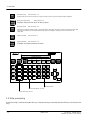
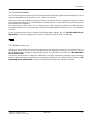
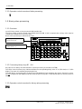
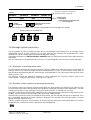
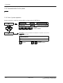
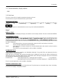
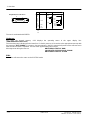
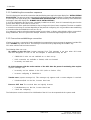
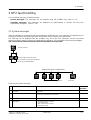
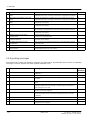
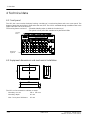
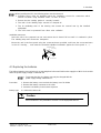
1
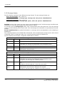
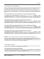
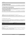
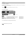
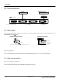
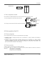
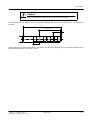
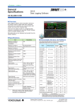
1 Overview
1 Function description
1.1 Function overview
The OP 2 is an operator control device for the SIMADYN D system. It offers the following performance scope:
Siemens AG 465 981.7101.23
SIMADYN D STRUC G User manual
Edition 02.96
1 ---1
1 Overview
Data processing,
refer to Section 1.2
VAL
Displays and processes up to 24 pieces of process data. 2 pieces of process data are always displayed.
BIN
Displays and processes up to 32 binary values.
Binary value processing,
Message system
refer to Section 1.3
refer to Section 1.4
MSG
Autonomous message system for P16 --- and P32 messages. Messages are stored, sorted according to the time that
they were received and can be deleted and printed. Only one message is displayed at any one time (max. 80
characters).
SYS
MSG
System message
refer to Section 3
System operation
refer to Section 1.5
SYSTEM
Changes and stores and basic function
SIMADYN OP 2
SIEMENS
Two- line display
40 characters per line
MSG
SEL
PRN
B1
V1
V2
DEL
B2
V4
B3
B4
ACT
OLD
SHIFT
DIM
CHG
EPROM
V3
1
2
3
V5
V6
4
5
6
V7
V8
V9
7
8
9
V10
V11
V12
0
.
+/--
SYS
MSG
SYSTEM
a
'
'
VAL
a
BIN
Enter
Numerical block
Process data panels V1..V12
Binary value keys B1..B4
1.2 Data processing
Data processing is selected using the VAL key. If data processing is selected, then the LED keys are lit (of the VAL
key).
1 ---2
Edition 02.96
Siemens AG 465 981.7101.23
SIMADYN D STRUC G User manual
1 Overview
1.2.1 General information
Two of a total of 24 pieces of process data can be simultaneously displayed (upper and lower display line). The 24
values are distributed over two panels (V1..V12 + SHIFT) for selection.
Both panels can be sub--divided according to the reference and actual values as required (for example, 20 actual
values can be configured or just 3). The distribution according to reference-- and actual values is exclusively realized
by the SIMADYN D configuring.
The selected process data values are, as default setting, always displayed normalized and with dimension
information and names. If a name hasn’t been configured, then the designator ”VALUE xy”(xy = 1 ..24) is displayed
as default.
If a non--configured process data is selected, the following display appears, No. 14 (”NO MEASURED VALUE
INITIALIZED”). This text is displayed for 3 seconds, and then the previous text is re--displayed.
ACC
1.2.2 Behavior at run--up
After OP2 has been initialized, it automatically goes into the data processing mode. The last selected values are
re--displayed. At first run--up, the first two configured values are displayed (normally the V1 and V2). If only one
process data has been configured, operating message No. 14 is displayed in the lower line (”NO MEASURED
VALUE INITIALIZED”).
If no process data have been configured in SIMADYN D, OP2 goes into the basic message system processing
function. If data processing is selected later, then operating message No. 14 is displayed in the upper line (”NO
MEASURED VALUE INITIALIZED”). The text is displayed until another basic function is selected.
Siemens AG 465 981.7101.23
SIMADYN D STRUC G User manual
Edition 02.96
1 ---3
1 Overview
1.2.3 Operator control overview of data processing
1.3 Binary value processing
1.3.1 Overview
Up to 32 binary values can be processed. (BIN and B1..B4).
The binary values cannot be stored in the SIMADYN D EPROM. If this is required, then a binary value must be
configured in SIMADYN D as process data.
Binary value processing is realized in two ways:
Processing the binary value menu
(binary values 5..32)
SIMADYN OP 2
SIEMENS
Two- line display
Each line, 40 characters
VAL
SEL
SHIFT
PRN
B1
V1
V2
DEL
B2
V4
ACT
B3
OLD
B4
DIM
CHG
V3
1
2
3
V5
V6
4
5
6
V7
V8
V9
7
8
9
V10
V11
V12
0
.
+/--
EPROM
SYS
MSG
SYSTEM
a
'
'
BIN
a
MSG
Processing the binary KEYS B1..B4
(binary values 1..4)
Enter
1.3.2 Processing binary keys B1 -- B4
Keys B1--B4 can always be selected unless system processing is selected (SYSTEM).
The LEDs in the four binary keys indicate whether the corresponding binary value is ”0”(LED dark) or ”1”(LED
bright). The status is inverted by depressing the key.
The LED flashes each time the KEY is depressed, until SIMADYN D acknowledges the change. If the binary values
are not configured on the SIMADYN D side, then the LEDs in keys B1-- to B4 remain dark (i.e. the keys have no
effect).
1.3.3 Operator control overview for binary value processing
BIN
1 ---4
Edition 02.96
Siemens AG 465 981.7101.23
SIMADYN D STRUC G User manual
1 Overview
Designator (configured in SIMADYN D)
Default designation: SIGNAL No.
Display:
MESSAGE-- CLASS
FULL
Change
0/1 changeover
ENTER
MESSAGE
SIGNAL 12
SIGNAL11
-- -- -- --
OFF
'
0
SIGNAL10
a
SIGNAL9
Status display:
- as display 0/1
- as text alternative (configurable text)
- - - - - if not configured
Select the next or previous
binary value
The status display flashes after each actuation until SIMADYN D acknowledges the change.
Running functions are ABORTED
SYSTEM
SYS
MSG
MSG
VAL
BIN
No function
1.4 Message system processing
The OP2 gathers all of the incoming messages into its own message system, where up to 30 messages can be
administered (stored). If more messages are received, then the first messages are overwritten (ring buffer
mechanism), and an overflow signal is entered into the buffer memory.
Operating message No. 15 (”MESSAGE LOST, QUANTITY: xx”), xx specifies the number of messages which were
overwritten.
Only one message can be displayed at any one time. OP2 chronologically sorts all of the received messages.
1.4.1 Evaluation of message class areas
An OP2 must not administer all messages which are sent from SIMADYN D. Message classes are assigned, as
selection criteria as to which messages should be administered by an OP2. These message classes must be
specified when parameterizing the OP2. All messages can be permitted, or, one, two or three message class areas
(refer to Section 1.5).
The message classes are defined in SIMADYN D when configuring the message systems (refer to the
communication-- configuring instructions; message class = prefix).
1.4.2 Operator control overview for message processing
The message system processing is selected via the MSG key. After selection, the LED key is lit. If the OP2 has
not received any messages, then operating message No.16 is displayed (”NO MESSAGES PRESENT”). The text
is displayed until either a new message is received or another function is selected (e.g. VAL key).
If the OP2 received new messages from SIMADYN D (since the last message system processing selection), then
the MSG key LED flashes if the message system processing is not selected.
If the message system processing is selected for the first time, the last selected message is re--displayed. If the
key is repeatedly depressed, the latest message is displayed. The selected OP2 message system is scrolled
through using the raise/lower keys.
The key actuation sequences for all functions in the message processing are subsequently listed. OP2 rejects
inadmissible key combinations with the appropriate acknowledgement.
MSG
Siemens AG 465 981.7101.23
SIMADYN D STRUC G User manual
Edition 02.96
1 ---5
1 Overview
1.4.3 Message display
The OP2 displays messages in two different message formats. The two message formats are:
` ASCII text messages: they consist of:
Date/time, message type, message text and process data/dimensions
` Prefix/suffix messages: they consist of:
Date/time, message type, prefix, suffix and process data/dimensions
Date/time consists of day, month, year, hour, minute, second and milliseconds. For P16 messages, the milliseconds
information is only to two decimal places (the OP2 inserts a ”blank”).
For P32 there are four message types: Alarm, fault, communications error and system error. The P32--message
system conventions/display forms must be used. For P16 messages, this information is not provided (OP2 inserts
a blank).
Process data/dimensions are optional information in a message, and are just dependent on the configuring in
SIMADYN D.
The configuring engineer on the SIMADYN D side decides, when configuring the message system, which format
is displayed (refer to Configuring Guides, P32-- and P16 communications for SIMADYN D).
The OP2 displays the messages, configured in SIMADYN D as follows:
Possible message formats for P32 messages:
Prefix/suffix
Text
Evaluation and display on OP2:
no
no
Message is not administered.
yes
no
The prefix is evaluated as message class. If the message class is
permissible, the message is administered in the prefix/suffix format.
no
yes
Messages without prefix/suffix with text are always administered in OP2.
yes
yes
The prefix is evaluated as message class. If it is valid, the message is
administered in the text format.
Possible message formats for P16 messages:
1 ---6
Prefix/suffix
Text
Evaluation and display on OP2:
no
no
Message is not administered.
yes
no
The prefix is evaluated as message class. If the message class is
permissible, the message is administered in the prefix/suffix format.
Example for P16 message text: ”#54321 #12345”.
no
yes
Messages without prefix/suffix, but with text, are always administered in
OP2.
Example for P16 message text: ”motor with overcurrent”.
yes (only
prefix)
yes
The prefix is evaluated as message class. If it is valid, the message is
administered in the text format. Otherwise it is rejected.
Example for P16 message text: ”#54321 motor with overcurrent”.
Edition 02.96
Siemens AG 465 981.7101.23
SIMADYN D STRUC G User manual
1 Overview
1.4.4 Description, ASCII text message
If there is a process data (with dimensions) included in a message, then the OP2 ”cuts”the message text after 28
characters if it is longer than these 28 characters (independent as to whether a dimension is included or not). If there
is no process data included, the message text may be 56 characters long (or the rest, is rejected by OP2).
If the message text is shorter than the maximum length, then the remaining characters are filled with blanks, i.e.
the display remains dark at these positions. Thus, the following message format is obtained at the display (2x40
characters) (d = day, m = month or minute, y = year, h = hour, z = milliseconds, T = message type (alarm, fault,
etc.)):
1) P32 message with process data (and dimension): maximum 28 message text characters
t t . mm. j j
h h : mm: s s . z z z
C H A R A C T E R S ! !
T
MA X .
-- 9 9 9 . 1 2 3 4 5 6 7 8
E ¦ 9 9
2 8
D I ME N S I O
2) P32 message without process data: maximum 56 message text characters
t t . mm. j j
h h : mm: s s . z z z
C H A R A C T E R S ,
R E C E I V E D
T
MA X .
F R O M
S I MA D Y N
D
5 6
! ! ! !
3) P16 message with process data (and dimension): maximum 28 message text characters
t t . mm. j j
h h : mm: s s . z z
C H A R A C T E R S ! !
MA X .
-- 9 9 9 . 1 2 3 4 5 6 7 8 9 0 1 2 3
2 8
D I ME N S I O
4) P16 message without process data: maximum 56 message text characters
t t . mm. j j
h h : mm: s s . z z
C H A R A C T E R S ,
R E C E I V E D
MA X .
F R O M
S I MA D Y N
D
5 6
! ! ! !
Example of a P32--message in the ASCII 2 text format with measured value (without dimension):
0 1 . 1 0 . 9 4
WI T H
0 0 : 0 0 : 0 5 : 1 6 7
U E -- C U R R .
W
MO T O R
O P E R A T E S
-- 9 9 9 9 9 . 1 2 3 4 5 6 7 E ¦ 9 9
”W”stands for the ”alarm”message type (is configured in SIMADYN D).
1.4.5 Prefix/suffix message
For ”prefix/suffix”format, the following message formats can be displayed at the OP2 (d = day, m = month or minute,
y = year, h = hour, z = millisecond, t = message type (alarm, fault etc.)):
1) P32 message with process data (and dimensions):
t t . mm. j j
h h : mm: s s . z z z
-- 9 9 9 . 1 2 3 4 5 6 7 8
Siemens AG 465 981.7101.23
SIMADYN D STRUC G User manual
E + 9 9
T
P : 5 4 3 2 1
S : 5 4 3 2 1
D I ME N S I O
Edition 02.96
1 ---7
1 Overview
2) P32 message without process data:
t t . mm. j j
h h : mm: s s . z z z
T
P : 5 4 3 2 1
S : 5 4 3 2 1
P : 5 4 3 2 1
S : 5 4 3 2 1
3) P16 message with process data (and dimensions):
t t . mm. j j
h h : mm: s s . z z
-- 9 9 9 . 1 2 3 4 5 6 7 8 9 0 1 2 3
D I ME N S I O
4) P16 message without process data:
t t . mm. j j
h h : mm: s s . z z
P : 5 4 3 2 1
S : 5 4 3 2 1
Example for a P16 message in the prefix/suffix format without measured value:
1 2 . 0 6 . 9 4
1 4 : 3 3 : 2 4 : 9 8
P :
3 2 9
S :
1
1.4.6 Message output on a printer
The message format at the printer is defined by the OP2, so that 2 display lines (i.e. a complete message) are
combined to form a printer line. Thus, OP2 automatically includes a line break after every message. Thus, a
message at the printer is always 80 characters long; the printer character length should be appropriately set. The
message structure is not changed by OP2.
Example for a message print--out:
Characters 1 -- 40
Characters 41 -- 80
12345678901234567890123456789012345678901234567890123456789012345678901234567890
1 1 . 1 0 . 9 4
2 0 : 1 3 : 4 4 : 5 7 1
W
MOT OR
NO
4
R P M:
-- 9 9 9 . 1 2 1 2 3 4 5 6 7 E ¦ 0 1
RPM
1.4.6.1 Initiating a print--out
The user can print--out all messages with the PRINT/OLD or PRINT/ACT keys (the two keys must be simultaneously
depressed).
For OLD/PRINT, all messages, including the just displayed message, are printed--out. For ACT/PRINT, that
message is printed--out, which is presently being displayed.
The messages are not automatically deleted after the print--out. Messages are only deleted via the DEL key.
1 ---8
Edition 02.96
Siemens AG 465 981.7101.23
SIMADYN D STRUC G User manual
1 Overview
1.4.6.2 Automatic printing
When parameterizing OP2, it must be specified whether messages should be printed--out immediately after they
have been received in OP2 (refer to 1.5.2 / PRINT MESSAGE DIRECTLY YES NO).
If YES is entered, then messages are printed--out as soon as the message telegram has been received. With this
type of print--out, there is not guarantee that the messages will be printed--out in the sequence in which they were
received.
Siemens AG 465 981.7101.23
SIMADYN D STRUC G User manual
Edition 02.96
1 ---9
1 Overview
1.5 System -- operation
In system operation, the basic settings (operating parameters) are defined for the OP2. The settings are
permanently stored in the FLASH memory.
SYSTEM
Selection
Depress the SYSTEM key for longer than 3 seconds.
1.5.1 Function overview
The following menu appears in the system mode:
MESSAGE
VALUE
PRINTER
END
MESSAGE
USS--INTERFACE
DISPLAY--OPTIONS
a
'
Operator control
CURSOR
Function selection
ENTER
Function start
a
'
Function:
MESSAGE
VALUE
USS--INTERFACE
PRINTER
DISPLAY--OPTIONS
Parameterization for the message system processing
Parameterization for data processing
Parameterization of the USS interface to SIMADYN D
Parameterization of the printer interface
Language selection for all OP2 messages
refer to Section 1.5.2
refer to Section 1.5.3
refer to Section 1.5.4
refer to Section 1.5.5
refer to Section 1.5.7
1.5.2 Parameterization for message system processing
1.5.3 Parameterization for process data
VA
1 ---10
Edition 02.96
Siemens AG 465 981.7101.23
SIMADYN D STRUC G User manual
1 Overview
1.5.4 Parameterization for the USS interface
USS--
Siemens AG 465 981.7101.23
SIMADYN D STRUC G User manual
Edition 02.96
1 ---11
1 Overview
1.5.5 Parameterization for the printer
1.5.6 End of system operation
System operation is ended by selecting END and depressing the ENTER key.
END
PRINTER
END
USS--INTERFACE
DISPLAY--OPTIONS
CURSOR
Function selection
a
'
'
VALUE
'
ENTER
MESSAGE
a
END
Description: If a new bus initialization to SIMADYN D is requested, ”YES”must be
specified, otherwise ”NO”
Display
INIT REQUEST
YES
'
1 ---12
Transfer
Edition 02.96
a
ENTER
YES NO
CURSOR
Function selection
Siemens AG 465 981.7101.23
SIMADYN D STRUC G User manual
1 Overview
1.5.7 Parameterization, display options
Displa
1.5.8 Self--test
The user can test all OP2 partial components using the self--test.
The self--test can only be selected from the system mode.
Starting the self--test:
The system mode is selected by pressing the SYSTEM key (longer than 3 seconds). The start of the self test is
initiated
by
simultaneously
depressing
the
following
keys:
a
'
. The particular function is selected with the cursor keys and confirmed with ENTER.
The fo
appear:
DISPLAY TEST:
Various test patterns are displayed. Display errors/faults can be visually checked. The test is ended with ENTER.
USS INTERFACE TEST:
Cyclic data are sent, simultaneously received and checked via the USS bus. During the test, the following message
is displayed in the upper line: ”USS--INTERFACE TEST --> ENTER FOR END”. After the end of the test, the
following message is displayed in the lower line: ”USS--INTERFACE OK”or ”USS--INTERFACE ERROR”(the test
is terminated with ENTER. In the case of the last--mentioned error message, the two following steps are executed
for further diagnostics:
Step 1:
Test without the bus connector inserted (this checks the USS bus interface of the OP2).
The OP must be replaced if a fault is identified.
Step 2:
Test with the bus connector inserted. It is not permissible that the bus master is active (check the
BUS wiring).
The wiring is incorrect/damaged if a fault condition is identified.
KEYBOARD TEST:
In the keyboard test, all key actuations are individually displayed. If keys with LEDs are depressed, then the
assigned LED is simultaneously lit.
When the keys are actuated, the particular descriptive text is displayed in the first line. When simultaneously
depressing two keys (exception: BIN and VAL), the DOUBLE KEY message is displayed. The test is terminated
by simultaneously depressing the BIN and VAL keys.
Possible faults :
-- when depressing a key, a message does not appear
--> key defective
-- when depressing a key, the DOUBLE KEY message is displayed --> keyboard defective
The OP must be replaced if a fault condition is identified.
PRINTER--INTERFACE TEST:
A test telegram is output to the printer via the printer port. The printer port can be tested using a short--circuit plug.
The short--circuit plug is assigned as follows:
Siemens AG 465 981.7101.23
SIMADYN D STRUC G User manual
Edition 02.96
1 ---13
1 Overview
Pin
Assignment, SS 1 and SS 2 A
8
15
1
9
1
2
3
4
5
6
7
8
9
10
11
12
13
14
15
General
V.24
Shield
RxD
TxD
CTS
Shield
TTY
RxD --
TxD+
TxD-RxD+
RTS
GND
+5V
GND
+20mA
GND
+20mA
The test is terminated with ENTER.
Hardware:
OP2 tests the internal memory. OP2 displays the operating status in the upper display line:
”RAM--EPROM--FLASH--TEST”.
The actual test step is displayed in the lower line. If a fault is present, OP2 remains at the appropriate test step with
the message ”TEST ERROR”. For an error--free test sequence, the OP2 automatically returns to the self--test menu
after the test has been completed. The test takes approximately two minutes.
Message texts during the test run:
WRITE READ TEST OF RAM
CALCULATE CHECK SUM OF EPROM
WRITE READ TEST OF FLASH
END:
End of the self test and a return to the SYSTEM mode.
1 ---14
Edition 02.96
Siemens AG 465 981.7101.23
SIMADYN D STRUC G User manual
1 Overview
2 System start
The OP2 is switched--on, by switching--in the +24 V power supply voltage. All connections must be correctly
connected--up to ensure perfect functioning of the unit:
-- USS connecting cable to SIMADYN D
-- Printer cable (if the printer is connected)
-- Power supply cable
2.1 Run--up
2.1.1 OP2 firmware release message
The following message appears for approximately 5 seconds after the unit has been powered--up: ”OP2 version
V1.0”(the actual firmware release is displayed).
2.1.2 Hardware test
The OP2 then automatically runs through a hardware test. The following messages are displayed in the sequence
during the run:
EPROM ok
Fault
EPROM--memory failure
(OP2 defective / replace)
RAM ok
Fault
RAM--memory failure
(OP2 defective / replace)
FLASH--TEST
Fault
FLASH--memory failure
(OP2 defective / replace
Fault
FLASH--memory erased
Fault
Incorrect FLASH--memory checksum
-- Incorrect contents / checksum of the flash memory
-- FLASH is being re--initialized
FLASH--TEST
-- -- --
-- Start with DEFAULT initialization
TEST ok
The unit then automatically establishes a connection to SIMADYN D.
2.2 Establishing the connection to SIMADYN D
After a successful OP2 self test, the connection is established to the SIMADYN D racks. The connection can either
be initiated from SIMADYN D or from OP2. For
` SIMADYN D: After a reset or the rack power supply has been switched--on
` OP2: After the OP2 power supply has been switched--on or optionally when the system mode is exited
(for the menu item ”INIT--REQUEST” in the ”END” main menu).
Siemens AG 465 981.7101.23
SIMADYN D STRUC G User manual
Edition 02.96
1 ---15
1 Overview
2.2.1 Establishing the connection--sequence
The OP2 displays the start of the connection with the following message in the upper display line: ”INITIALIZATION
REQUESTED”. The process value is automatically initialized after the first information is exchanged with SIMADYN
D (message in the upper display line: ”PROCESS DATA INITIALIZATION”) and then the binary value initialization
(message in the lower display line: ”BINARY VALUE INITIALIZATION”).
If all of the initialization data have been completely loaded into the OP2, then OP2 automatically goes into the
process data display mode (refer to Section 1.2).
The OP2 remains at the particular initialization step as long as this hasn’t been completed. The time to establish
a connection can take up to a minute depending on the particular configuring. It is only possible to start establishing
a connection after the SIMADYN D rack has run--up.
If an attempt is made to select the operating modes, process data-- or binary values display, while a connection is
being established, then OP2 ignores this attempt. However, received message telegrams are processed.
2.2.2 Errors when establishing a connection
If faults occur when a connection is being established, an appropriate system message is generated, and the LED
on the SYSMSG key starts to flash. The message can be read--out by depressing the SYSMSG key.
OP2 waits until the fault has been removed.
The following faults can occur:
` No activity on the USS bus (system message S24). This message is set once when OP2 starts
and then disappears as soon as the first telegram is transmitted along the bus.
f SIMADYN D racks are not switched--on or don’t run--up
f BUS connection not available or faulted, cable not inserted.
f Incorrectly set baud rate
` No SCAN telegram with the node number of the OP2 after the protocol monitoring time expires
(system message S25).
f Incorrectly set bus address in the OP2 (refer to Section 1.5.4).
f Incorrect configuring in SIMADYN D
` Transfer error (system message S4). This message only appears until a correct telegram is received.
f Disturbance/fault on the line, incorrect baud rate
` Erronous INIT data The received data are logically incorrect
f Fault/disturbance on the line, incorrect baud rate
f Check the configuring
The faults/errors must be removed. Re--initialization of the OP2 can be requested via the system mode.
1 ---16
Edition 02.96
Siemens AG 465 981.7101.23
SIMADYN D STRUC G User manual
1 Overview
3 OP2 fault handling
OP2 can identify two types off fault messages:
` System messages: The messages can be analyzed using the SYSMSG key. (refer to 3.1)
` Operating messages: The messages are displayed for approximately 3 seconds and they then
automatically disappear. (refer to 3.2).
3.1 System messages
If the OP2 identifies an error/fault during parameterization, initialization or in cyclic operation, an appropriate error
message is entered in the system error field, and the LED in the SYSMSG key starts to flash.
The message can be displayed with the SYSMSG key. All of the error messages and the associated
counter--measures and error causes are described in the following. The errors/faults cannot be acknowledged.
The cause must be removed otherwise fault--free operation is not possible.
Function selection
'
a
SYS
MSG
Scroll through all active messages
If no message is active: Message display
No.19 (NO SYSTEM ERROR)
Running functions are ABORTED
SYSTEM
MSG
VAL
BIN
BIN
Only possible after the INIT phase
SYS
MSG
No function
These are the system messages:
N
o
Text
Description / cause / measures
Reference
10
INITIALIZATION ERROR MEASURED
VALUE NO.
Error for an INIT telegram for process data. Repeat initialization. Check the
configuring
2.2.1
18
NO PRINTER BUFFER FREE
The printer cannot print--out the message fast enough. Messages are lost.
Check the printer and printer connections.
1.4.6
19
NO SYSTEM ERROR
System operation: No error messages are active
3
23
DATA TRANSFER ERROR, CHECK
HARDWARE,
Data transfer errors occur on the USS bus:
-- Disturbances/faults on the line
-- Incorrect baud rate
-- BUS conflict on the USS BUS
-- Defective bus cable
2.2
Siemens AG 465 981.7101.23
SIMADYN D STRUC G User manual
Edition 02.96
(Section)
1 ---17
1 Overview
24
SYSTEM ERROR
Unit not functioning. Fatal electronics fault
General info.
25
INIT ERROR, NO MEASURED VALUE INIT.
DATA
Process data initialization incomplete. OP2 expects additional process
initialization data. OP2 is not ready. Check the bus configuration and software.
2.3
26
INIT. ERROR, NO BINARY VALUE INIT.
DATA
Process data initialization incomplete. OP2 expects additional binary value
initialization data. OP2 is not ready. Check the bus configuration and software.
2.3
27
INIT. ERROR, MEASURED VALUE--INIT.
DATA
Erroneous initialization data for process data. OP2 is not ready. Check the bus
configuration and software.
2.3
28
INIT. ERROR, BINARY VALUE -- INIT.DATA
Erroneous initialization data for binary values. OP2 is not ready. Check the bus
configuration and software.
2.3
29
MEASURED VALUE CHANGE ERROR
Process data change error. Unsuccessful process data change in the
VAL/CHANGE mode. Repeat the function and if required check the software.
1.2.3
30
INITIALIZATION ERROR, DELAY
Time monitoring exceeded during initialization. OP2 not ready. Check the bus
configuration and software.
2.3.2
31
INTERRUPTION TO THE HOST
CONNECTION
No USS telegrams received.
Check the bus connection/cable
2.2
32
NO BUS CONNECTION, INCORRECT
STATION ADDRESS
No telegrams are received with their own station address. Configuring error or
incorrectly set bus address.
2.2 + 1.5.4
33
PRINTER NOT READY OR NOT
CONNECTED
OP2 cannot print. The printer does not respond. Check the printer and printer
connecting cable.
1.4.6
35
EPROM SAVE UNSUCCESSFUL
Unsuccessful data save in the EPROM, VAL/CHG mode. Check the software.
1.2.3
36
TELEGRAM ERROR, NO BUS
CIRCULATION
Check the bus configuration, check the configuring, master is not sending
SCAN telegram with the OP node number.
2.2
3.2 Operating messages
Information texts, alarms and fault/error messages are displayed for approximately three seconds as operating
messages in order to help the user when problem situations occur.
Text
Description / Cause / Measures
Reference
1
MEASURED VALUE NOT INITIALIZED
A process data number V1..V24 was selected, which was not configured in
SIMADYN D
1.2
2
FUNCTION NOT PERMITTED
Function not permitted in the current processing mode
Gen. info.
3
UPPER LIMIT EXCEEDED
When entering or changing a setpoint, the configured upper limit was
exceeded.
1.2
4
LOWER LIMIT FALLEN BELOW
When entering or changing a setpoint, the configured lower limit was fallen
below.
1.2
5
SETPOINT CHANGE INHIBITED
When selecting the change mode for a process data, the change was not
enabled by SIMADYN D. It is presently occupied/changed by another OP, or
was configured as ACT value.
1.2
6
LAST CHANGE STILL NOT ACCEPTED
The last process data change was not accepted by SIMADYN D. Repeat the
function or check the configuring.
1.2
7
DELAY TIME EXPIRED
The actual change of a process data was still not accepted by SIMADYN D.
The monitoring time has been exceeded. Repeat the function or check the
configuring.
1.2
8
FUNCTION NOT POSSIBLE
A key was depressed, which was not possible in the current processing mode
Gen. info.
9
INCORRECT INPUT
An invalid value was entered.
Gen. info.
INITIALIZATION RUNNING
OP2 waits for general INIT data. OP2 not ready, if required, check bus
configuration and configuring.
2.2.1
No
11
1 ---18
Edition 02.96
(Section)
Siemens AG 465 981.7101.23
SIMADYN D STRUC G User manual
1 Overview
12
MEASURED VALUE INITIALIZATION
OP2 waits for process data initialization. OP2 not ready, if required check the
bus configuration or configuring.
2.2.1
13
BINARY VALUE INITIALIZATION
OP2 waits for binary value initialization. OP2 not ready, if required check the
bus configuration or configuring.
2.2.1
14
NO MEASURED VALUE INITIALIZED
No process data were initialized and configured; the VAL function is not
possible
1.2
15
NUMBER OF LOST MESSAGES:
Message processing overflow message. This message is entered as the latest
message in the message buffer. The oldest messages are overwritten by the
latest messages. The number of lost messages are counted until messages
are deleted with DEL.
1.4
17
NO FURTHER MESSAGES PRESENT
The message buffer was scrolled past its end.
1.4
20
RAM--TEST UNSUCCESSFUL, REPLACE
THE UNIT
OP2 electronically defective and not functioning: Self--test message
2.1.2
21
FLASH--TEST UNSUCCESSFUL,
REPLACE THE UNIT
OP2 electronically defective and not functioning: Self--test message
2.1.2
22
EPROM--INCORRECT EPROM
CHECKSUM, REPLACE THE UNIT
OP2 electronically defective and not functioning: Self--test message
2.1.2
34
INITIALIZATION REQUESTED
OP2 waits for initialization data.
2.3
35
EPROM SAVE UNSUCCESSFUL
Mode VAL/CHG/ EPROM save unsuccessful
Check the configuring.
1.2.3
37
PRINTER INTERFACE O.K.
Self--test message
38
DEFECTIVE PRINTER INTERFACE
Self--test message
39
CALCULATING EPROM CHECKSUM
Self--test message
40
RAM READ/WRITE TEST
Self--test message
41
FLASHRAM READ/WRITE TEST
Self--test message
42
TEST OK
Self--test message
Siemens AG 465 981.7101.23
SIMADYN D STRUC G User manual
Edition 02.96
1 ---19
1 Overview
4 Technical data
4.1 Front panel
The OP2 has a two--section aluminum housing, consisting of a cast housing frame and a rear cover panel. The
degree of protection at the front is IP65 and at the rear, IP20. The OP2 is ventilated through ventilation slots in the
upper and lower side of the housing.
The housing frame consists of: -- Insertable labeling strips (to label the function keys)
-- The glued--in front panel with membrane keyboard and LEDs
Housing
frame
SIMADYN OP 2
SIEMENS
MSG
BIN
VAL
PRN
B1
V1
V2
V3
1
2
3
DEL
B2
V4
V5
V6
4
5
6
ACT
B3
V7
V8
V9
7
8
9
OLD
B4
V10
V11
V12
0
.
+/--
SEL SHIFT DIM
CHG
E2
PROM
SYS
MSG
SYSTEM
a
a
'
'
Membrane
keyboard
Two- line display
Each line, 40 characters
Enter
157
168
130
4.2 Equipment dimensions and mechanical installation
240
8
40
229
The OP2 can be mounted in cabinets or desks:
` Mounting cut--out:
230 x 158 mm
` Mounting depth:
40 mm
` Max. front panel thickness:
16 mm
1 ---20
Edition 02.96
Siemens AG 465 981.7101.23
SIMADYN D STRUC G User manual
1 Overview
When installing the OP2, the following points must be observed:
S Sufficient space must be provided below the installation cut--out for connectors which
extend out (when using standard cables, at least 20 mm)!
S Ensure that the sealing gasket is correctly located!
S The tabs of the labeling strips mustn’t be clamped--in!
S The air ventilating slots of the housing rack mustn’t be covered over by the installed
equipment!
S The OP2 must be protected from direct solar radiation!
Installation measures:
` Insert the unit in the prepared cut--out and ensure that it doesn’t fall out until it is retained in place.
` The labeling strip tabs mustn’t be clamped--in
` Mount the unit in the front panel using the screw tensioners provided, and insert the screw tensioners
in the OP housing ¡ and rotate the threaded spindles backwards against the front panel © , ¢ .
Threaded spindle
Allen key
©
¡
¢
Unit rear side
4.3 Replacing the batteries
The Lithium batteries are used to back--up operating data in the static RAM and to supply the CMOS clock module
when the power supply voltage is switched--out
To prevent data loss, the battery may only be changed with the
power supply voltage switched--on!
Procedure:
1. Remove the battery cover and take the battery out of its holder
2. Remove the battery connector to the cable
3. Insert the new battery in the inverse sequence
Battery type:
3 V, 480 mAh Lithium cell
Caution
Please observe the ESD guidelines and the safety--related information for
Lithium batteries in the preamble to Section 4 of the Equipment Manual.
Siemens AG 465 981.7101.23
SIMADYN D STRUC G User manual
Edition 02.96
1 ---21
1 Overview
4.4 Connecting element
Printer
SIMADYN D control
DR210/211--N, DR230/231--N
USS master
USS bus
OP2
(Lower side of the unit)
RS485
V.24/TTY
SS1/IF1
Terminal block / voltage power supply
SS2A/IF2A
SS2B/IF2B
Unused (V.24/TTY)
Ground connection
4.5 Power supply
The 4--pole terminal block is used to connect--up the power supply voltage and the authorization input. The
authorization input is not used.
Connecting-- up individual cables
Terminal block connections
1
4
AE
Unused
A+
7 mm
0 V +24 V DC
power supply
voltage
Cable cross--section which can be used: 0.5 ...2.5mm
4.6 Baud rates
OP2 can be operated on the USS bus with the following baud rates: 9.6 / 19.2 / 93.75 / 187.5 Kbaud.
4.7 Cable and connectors
4.7.1 Connector assignment
OP2 is always connected at the SS 2B interface (RS485 / USS bus).
1 ---22
Edition 02.96
Siemens AG 465 981.7101.23
SIMADYN D STRUC G User manual
1 Overview
Assignment SS 2B
5
1
9
Pin
1
2
3
4
5
6
7
8
9
6
RS 485
Data B
GND
+5V
Data A
4.7.2 Bus configuration and cable
The connection is realized through the 9--pin sub--D connector with the following circuitry:
B
A
A) Circuit configuration as node at the center of the bus
(3) DATA B
(8) DATA A
BUS cable
B
A
9 --- pin, Sub--- D
B) Circuitry as node at the end of the bus (with bus termination)
(6) +5V
(3) Data B
(8) Data A
(5)
.
End
390 O
150 O
390 O
BUS cable
B
A
9 --- pin, Sub--- D
4.8 Printer operation at the OP2
4.8.1 Printer configuration
The OP2 printer interface at the unit can be parameterized in two settings:
1) XON/XOFF protocol; formatted message texts are transferred to a printer, whereby the formatting is
executed by OP2.
2) XON/XOFF protocol with ETX/ACK; formatted message texts are transferred to a printer, whereby
formatting is realized by the OPP2. OP2 transmits an ETX (end of text) after every message, which
is then acknowledged by the printer with ACK (acknowledge) (e.g. Mannesmann Tally printer). Only
then can be the OP2 transmit a new message.
4.8.2 Printer connection
A printer is always connected at the SS1 interface of the OP2.
Pre--assembled cables are available for the following Siemens printers: DR210--N / DR211--N / DR230--N /
DR231--N
-- 6XV1 440--2B... for TTY transfer
-- 6XV1 440--2C... for V.24 transfer
...
= length code, refer to Catalog ST80
Siemens AG 465 981.7101.23
SIMADYN D STRUC G User manual
Edition 02.96
1 ---23
1 Overview
These cables can also be used for PT88/89/90 printers. It may be necessary to assemble cables for other printers.
SIEMENS AG does not accept any liability for incorrect functions and damage, which
result from using self--assembled cables or cables from other manufacturers!
Pin
1
2
3
4
5
6
7
8
9
10
11
12
13
14
15
Assignment, SS 1 and SS 2 A
8
1
15
9
General
V.24
Shield
RxD
TxD
CTS
Shield
TTY
RxD --
TxD+
TxD-RxD+
RTS
+20mA
GND
+5V
GND
+20mA
4.9 Labeling and replacing the labeling strips
The OP2 function keys are labeled when supplied with B1 to B4 and V1 to V12. A set (4) of unlabeled strips are
provided with the OP2 for your own key labeling. When used, they cover over the standard labeling.
CAUTION
Before attaching the labeling strips, the labeling must be absolutely
non--smearable, as ink smeared on the inside of a membrane
keyboard cannot be removed.
The front panel can only be replaced in the service workshop at a considerable cost.
If required, remove all of the old labels at the tabs. Insert the labeled strips (non--smearing labeling -- cautiously to
their end stop until they cannot be inserted any further.
OP2
(Lower unit side)
SS1/IF1
SS2A/IF2A
SS2B/IF2B
For already installed OP2 units, it is recommended that the screw tensioners are loosened and the unit cautiously
pulled forward out of the mounting cut--out.
1 ---24
Edition 02.96
Siemens AG 465 981.7101.23
SIMADYN D STRUC G User manual
1 Overview
Caution
It is not permissible to hang an OP2 by its connecting cables!
The following dimension diagram shows an individual labeling strip and the visible fields (which can be used for
labeling):
88
3 x 16.7 = 50.1
16.7
2.5
14.2
14 (4x)
When producing your own labeling strips, according to the dimension drawing above, it must be ensured that the
material thickness does not exceed 0.1 mm!
Siemens AG 465 981.7101.23
SIMADYN D STRUC G User manual
Edition 02.96
1 ---25