1
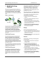
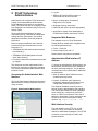
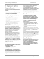
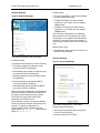
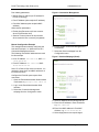
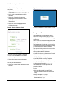
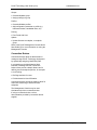
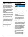
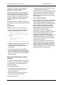
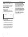
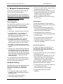
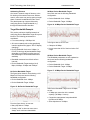
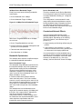
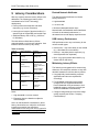
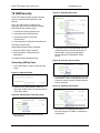
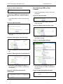
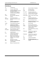
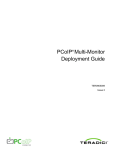
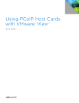
TER0806003
PCoIP® Technology User Guide
Volume I
July, 2008
Issue 1
Teradici Corporation
500 – 4400 Dominion St.
Burnaby, BC, Canada V5G 4G3
Abstract
This document outlines PCoIP Technology user features.
© 2008 Teradici Corporation
PCoIP Technology User Guide (Vol I)
Introduction
The PC-over-IP® (PCoIP®) Technology User
Guides summarize features of the PCoIP
System.
The following topics are covered in the PCoIP
Technology User Guide Volume I:
Introduction .............................................. 2
1
PCoIP Technology Overview............. 3
2
PCoIP Technology Administration..... 5
3
Deployment Options .......................... 7
4
Discovery Mechanisms....................12
5
Network Considerations ..................14
6
Bandwidth Considerations...............16
7
Imaging Considerations...................17
8
Network Characterization ................18
9
Latency Considerations ...................21
TER0806003 Issue 1
Configuration Examples
Please note that this document uses the
Administration Web Interface for parameter
configuration examples. Refer to the
Administrative Interface User Manual [1] more
detail on the parameters summarized in this
document.
Other tools, such as the Management Console,
can provide similar functionality. Refer to related
tool manuals for more information.
10 USB Security ...................................22
Definitions...............................................24
References .............................................25
Revision History .....................................25
The descriptions in this document are meant to
provide functional overviews with examples
where relevant. It is recommended to review
reference documents for more information.
© 2008 Teradici Corporation
Page 2 of 25
PCoIP Technology User Guide (Vol I)
TER0806003 Issue 1
1 PCoIP Technology
Overview
This process of compression, transmission, and
rebuilding the desktop occurs in a very short
time, typically less than one display frame
update, to ensure desktop responsiveness.
The PCoIP Technology solution provides a no
compromise method to remote a user’s desktop
over an existing IP network. This functionality
includes full DVI dual monitor video, complete
USB compatibility, and full-duplex high definition
audio.
A PCoIP Portal can be a desktop device or be
integrated into a monitor.
Figure 1: PCoIP System
Operating Systems and Applications
The following summarizes Operating System
and Application compatibility:
• PCoIP Technology is operating system
unaware
• Extensively tested with Windows® XP® and
Windows Vista® (32-bit)
• PCoIP Technology does not require special
drivers to be installed and uses standard USB
and HD Audio device drivers
Teradici’s PCoIP Technology uses networking
and proprietary encoding/ decoding technology
to remote connections between the Host
PC/Workstation and Portal via a standard IPnetwork. Using a PCoIP Technology remote
connection, a user can operate the host PC and
use the desktop peripherals as if the host PC
were local.
PCoIP Host Processor
The PCoIP Host Processor connects into the
host PC or workstation via the digital video
interface (DVI) and PCIe bus. The pixels from
the video interface are encoded and sent to the
Portal. The PCIe bus connection provides
transparent bridging of USB peripherals and HD
Audio using the standard USB and audio drivers
provided by the OS.
Prior to transmission, the PCoIP Host Processor
compresses the video stream and combines the
bridged audio and USB traffic.
PCoIP Portal Processor
At the desktop, the PCoIP Portal Processor
decompresses and distributes the video, audio
and USB data. In the return path, the PCoIP
Portal Processor combines audio and USB
peripheral data, for transmission back to the
Host.
© 2008 Teradici Corporation
• PCoIP Technology is compatible with all PC
applications as no hardware or OS changes
are required in the host PC
Display
PCoIP Technology display attributes are:
• Provides a perception free experience with low
latency, full frame rate video for the same user
experience as a local PC
• Progressive build to deliver exact image of the
rendered host display
Network
Related PCoIP Technology networking points
are summarized:
• Uses existing IP network and co-exists with
existing IP data
• PCoIP Technology optimizes the user
experience for a given bandwidth by
adaptively controlling quality and update rate
of the image data, and optionally compressing
the audio stream
• PCoIP Technology will adapt to changing
network environments and use less bandwidth
when network congestion is present
• PCoIP Systems can be optimized towards
minimal bandwidth usage for lower bandwidth
situations, e.g. corporate WAN
Page 3 of 25
PCoIP Technology User Guide (Vol I)
TER0806003 Issue 1
I/O
The following input and output capabilities are
provided with PCoIP Technology:
• Fully bridged functionality for any USB device
(including USB 2.0 at USB 1.1 data rates)
• Full bi-directional digital audio, allowing a full
multimedia experience
Security
PCoIP Technology features are summarized
below:
• The Portal is a stateless desktop appliance
that has no locally stored host data or
embedded Windows or Linux operating
system to be compromised
• Secure Host/Portal communication consists of
the control data stream and the media data
stream. The control data stream is secured
using digital certificates for mutual
authentication. The media data stream is
secured using the AES encryption algorithm
• USB access from the Portal is fully
configurable and customizable. USB
permissions may be restricted or authorized
by Class or Vendor/Device ID. Any restricted
USB devices will be terminated at the Portal to
ensure security will not be compromised
IT Support
PCoIP Technology has the following IT support
related features:
• Neither the Host nor Portal use an embedded
Windows or Linux operating system
• The PCoIP Portal does not require customized
drivers for peripheral support. All USB devices
are transparently bridged back to the host PC
or workstation
• PCoIP System remotes the familiar PC user
experience reducing end-user training
requirements
• The Portal can also be used as a universal
desktop and is also capable of providing a
RDP client for users that may not require the
high-fidelity experience of PCoIP Technology
© 2008 Teradici Corporation
Page 4 of 25
PCoIP Technology User Guide (Vol I)
TER0806003 Issue 1
2 PCoIP Technology
Administration
• Log Out
Administrators can configure PCoIP Hosts and
Portals via the Administrative Web Interface,
PCoIP Management Console or a connection
broker. The Portal can also be configured via the
local Graphical User Interface (GUI) On Screen
Display (OSD).
• Menus: Configuration, Permissions,
Diagnostics, Info, Upload
These tools allow administrators to assign
Host/Portal peering, view/change configuration
settings and user permissions, view session
diagnostics information, and view peripheral
information.
Each tool supports a different set of features.
Consult the product documentation for more
information, i.e.:
• TER0606004 PCoIP Administrative Interface
User Manual [1]
• TER080601 PCoIP Management Console
Quick Start Guide [2]
• Connection broker documentation as provided
by supplier
• TERA1100 Portal PCoIP Processor or
TERA1200 Host PCoIP Processor
• Webpage summary information
• Data field (with inline help when appropriate)
• Apply/Cancel (Apply stores parameters in
FLASH/Cancel resets values as in FLASH)
Supported Web Browsers
The webpage server on PCoIP Hosts and
Portals has been tested and is compatible with
the following web browsers:
• Firefox 1.5 and 2.0
• Internet Explorer 6.0 and 7.0
Other browsers may also be compatible.
Administrative Web Interface IP
Address
This document uses the Administration Web
Interface for parameter configuration examples.
This section outlines basic Administration Web
Interface access.
To access the Administrative Web Interface, the
administrator must browse to the IP address of
the Host and Portal endpoints. The IP address
used depends on the method that IP addresses
are determined:
Accessing the Administrative Web
Interface
• Static IP Address: the IP address is hard
coded and must be known
The PCoIP Administrative Web Interface allows
administrators to configure endpoints remotely
using a browser.
Figure 2: Administration Web Interface
• Dynamic IP Address: the IP address is
dynamically assigned by the Dynamic Host
Configuration Protocol (DHCP) server
The endpoint IP address must be known to
access using the Administrative Web Interface.
This can be determined from either knowledge
when configuring, or discovering via DHCP
server or a discover mechanism. Once the IP
address is determined, it can be entered into the
browser to access the Administrative Web
Interface, e.g. https://192.168.1.123.
Web Interface Security
The web interface uses HTTP over an SSL
socket (HTTPS), and cannot be accessed
without an administrative password. The HTTPS
connection is secured using a Teradici selfsigned certificate.
The figure above shows the Administrate Web
Interface with six regions highlighted;
© 2008 Teradici Corporation
Page 5 of 25
PCoIP Technology User Guide (Vol I)
CA Root Certificate Installation
TER0806003 Issue 1
Figure 3: Log In Webpage
A Certificate Authorities (CA) root certificate can
be installed in the internet browser to avoid the
browser security warnings. Steps for installing
the certificate on Internet Explorer 7 and Firefox
are detailed below:
Internet Explorer 7
1. Open the Tools menu and select Internet
Options
2. On the Content tab, select Certificates
3. On the Trusted Root Certification Authorities
tab, select Import
4. Follow the directions to import the certificate
– ensure to use the Trusted Root Certification
Authorities certificate store.
Note: When browsing for the certificate, it may
be necessary to change the file type to all files.
Firefox
1. Open the Tools menu and select Options
Figure 3 shows the Administrative Web Interface
Log in Webpage;
• Warning message displays pertinent
information regarding the end point that the
administrator is logging in to
2. Select the icon labeled Advanced at the top
of the window
• Password - allows access to the
administration webpage (default value is
blank, i.e. “”)
3. On the Encryption tab, select View
Certificates
• Idle Timeout (1 minute, 5 minutes, 15 minutes,
30 minutes, Never)
4. On the Authorities tab, select Import
5. Follow the directions to import the certificate
– ensure to check the option labeled Trust
this CA to identify web sites
Log In
The Log In page allows the administrator to
securely log into the administrative webpages.
© 2008 Teradici Corporation
Page 6 of 25
PCoIP Technology User Guide (Vol I)
TER0806003 Issue 1
3 Deployment Options
reserve a range of network IP addresses for
PCoIP Technology deployments.
Deployment Scenarios
It is recommended to use DHCP for larger
deployments as the overhead of managing static
IP addresses can become burdensome. If
DCHP is used, it is recommended to use a
discovery mechanism to avoid ‘losing’ endpoints
in an IP network (see Section 4 ).
There are four PCoIP Technology deployment
scenarios:
• Basic 1:1 – use default configuration settings
to pair Host/Portal endpoints (limited to 1
Host/Portal pair on simple network)
• Manual Configuration – manually enter
Host/Portal pairings (less time efficient for
larger deployments)
• Management Console – simple tool to
automate pairings and management
(recommended for medium sized
deployments)
• Connection Broker – 3rd party management
entity often with extended features
(recommended for large deployments)
DHCP vs. Static IP
Host and Portals are configured with DHCP
(Dynamic Host Configuration Protocol) enabled
by default. If connected to a DHCP server, Host
and Portal IP addresses will be dynamically
assigned. Assigned IP address configuration
information can be found in the Network
Webpage (see below).
When DHCP is used and default settings are
used, the Host and Portal populate the DHCP
server with a hostname in the form of pcoiphost-mac.domain or pcoip-portalmac.domain, where mac is the 6 octet device
MAC address, and domain is the local domain.
If a DHCP server is not present, the endpoints
will fallback to static IP addresses (120 seconds
after startup). The static IP addresses are:
• Host: 192.168.1.100
• Portal: 192.168.1.50
The Host and Portal will also have the following
configuration for fallback:
Basic 1:1
The Host and Portal firmware IP address
defaults facilitate a PCoIP Session without
detailed configuration. This deployment can be
used when a simple remote experience is
desired with little or no endpoint management.
The Basic 1:1 configuration supports the
following scenarios:
• Direct connection from Host to Portal with
single Ethernet cable (cross over cable not
required)
• Connection from Host to Portal via IP
switch(es)
When using a direct connection without an IP
switch, the Host and Portal endpoints can not be
managed, for example, by the Administrative
Interface.
Note: Since all endpoints fallback to the static IP
addresses above, no more than one Host/Portal
pair can be used on the simple IP network. The
above static IP addresses may also conflict with
other network equipment if the fallback
addresses are already in use.
Manual Configuration
Manual pairing of Hosts and Portals are a quick
and easy way to associate PCoIP Hosts and
Portals for smaller deployments.
When using the Administrative Interface, the
Network and Session webpages are used for
manual configuration.
• Subnet Mask: 255.255.255.0
• Gateway: 192.168.1.0
For small deployments, it may be preferred to
use static IP addresses. Static IP addresses can
also be used in a DHCP network if care is taken
not to use IP addresses reserved for DHCP. If
using static IP addresses, it is recommended to
© 2008 Teradici Corporation
Page 7 of 25
PCoIP Technology User Guide (Vol I)
TER0806003 Issue 1
Network Webpage
Ethernet Mode
Figure 4: Network Webpage
• Auto (recommended – link will auto negotiate
to proper network data rate)
• 10 Mbps Full-Duplex (use when network
equipment, e.g. IP switch, can only support
10Mbps links)
• 100 Mbps Full-Duplex (use when network
equipment, e.g. IP switch, can only support
100Mbps links)
Note: Improper configuration of the Ethernet
Mode may result in a Half-Duplex link. PCoIP
Technology is not compatible with Half-Duplex
operation; a warning overlay will be shown on
Portal display and the session will eventually be
lost.
Maximum MTU Size
• See Maximum Transmission Unit in Section 5,
Network Considerations)
The Network webpage has 8 parameters:
IP Address Fields
• Enable DHCP (see DHCP vs. Static IP above)
Session Webpage
Figure 5: Session Webpage
• IP Address (endpoint IP address must be
entered for static IP addressing)
• Subnet Mask (subnet mask for endpoint must
be entered for static IP addressing)
• Gateway (gateway must be entered for static
IP addressing)
• Primary DNS Server (provided by DHCP
server when DHCP is enabled)
• Secondary DNS Server (provided by DHCP
server when DHCP is enabled)
When using static IP addressing, the IP address
fields can be used to specify the IP address on
the Host or Portal endpoints on the network.
When DHCP is used, these fields will be
populated via the DHCP server.
Every endpoint must have a unique IP address
that will not conflict with other equipment on the
network. To simplify configuration, it is
recommended to keep all endpoints on the
same subnet, e.g. 192.168.1.x and a Subnet
Mask of 255.255.255.0.
The Session webpage has 7 parameters:
General session parameters:
• Accept Any Peer (allows Host to accept any
Portal for PCoIP Session)
• Session Type (PCoIP vs. RDP)
© 2008 Teradici Corporation
Page 8 of 25
PCoIP Technology User Guide (Vol I)
Peer Identity parameters:
TER0806003 Issue 1
Figure 6: Connection Management
• Identify Peer by method (use IP address for
PCoIP Technology)
• Peer IP Address (other endpoint IP address)
• Peer MAC Address (other endpoint MAC
address)
Other session parameters:
• Enable Auto-Reconnect (will auto connect
when PCoIP Session lost)
• Session Timeout (timeout to drop session
when network is lost or severely congested)
Manual Configuration Example
This example shows manually configuring the
Host and Portal pair, i.e. without the use of a
Connection Management Server.
The following IP and MAC addresses are used
for this example:
• Host: IP Address: 192.168.0.20, MAC: 0019-D2-6F-EC-6C
6. Ensure Enable Connection Management is
not selected
7. Select the Session webpage from the
Configuration menu
Figure 7: Session Webpage (Portal)
• Portal: IP Address: 192.168.0.34, MAC:
6C-EC-6F-D2-19-00
Note: For a Peer-to-Peer direct connection, it is
required to know the IP and MAC addresses of
the Portal and Host.
Configure the Portal for peer-to-peer direct
connection:
1. Open the Portal Administration Web Interface
in a browser, e.g. https://192.168.0.34
2. Log in to the Portal Administration Web
Interface
3. Select the Connection Management
webpage from the Configuration menu
8. Select IP address next to Identify Peer by
9. Enter Host IP address in Peer IP Address,
e.g. 192.168.0.20
10. Enter Host MAC address in Peer MAC
Address, e.g. 00-19-D2-6F-EC-6C
11.Select Apply button to accept changes
© 2008 Teradici Corporation
Page 9 of 25
PCoIP Technology User Guide (Vol I)
Configure the Host for peer-to-peer direct
connection:
TER0806003 Issue 1
Figure 9: Connect Screen
12. Open the Host Administration Web Interface
in a browser, e.g. https://192.168.0.20
13.Log in to the Host Administration Web
Interface
14.Select the Connection Management
webpage from the Configuration menu
15. Ensure Enable Connection Management is
not selected
16.Select the Session webpage from the
Configuration menu
Figure 8: Session Webpage (Host)
21. When connected, the Host computer is ready
to use over PCoIP
Management Console
The Management Console (MC) is a tool to
assist in the configuration of Host and Portal
endpoints for medium sized PCoIP Technology
deployments.
The MC is a HTML based virtual appliance that
is packaged with the minimum required OS.
The Management Console can also be used in
conjunction with a connection broker to manage
the configuration of the PCoIP endpoints
The expected deployment environments for the
MC are:
• Single subnet static IP addresses
17. Ensure Accept Any Peer is not selected
18. Enter Portal MAC address in Peer MAC
Address, e.g. 6C-EC-6F-D2-19-00
• Use SLP for discovery (Management Console
discovers endpoints)
• DHCP w/ DNS server deployments
19.Select Apply button to accept changes
• Use DNS-SRV for discovery (endpoints
discover Management Console)
Start the peer-to-peer session:
Note: The DNS-SRV Resource Record name for
the Management Console is pcoip-tool.
20.Select the Connect button to start the PCoIP
session
The Management Console capabilities are
summarized below:
Devices
• Add newly discovered Host and Portal
endpoints (and give endpoints a descriptive
name)
• Assign a endpoint to a group
• View endpoint info (e.g. firmware revision,
attached devices, etc)
© 2008 Teradici Corporation
Page 10 of 25
PCoIP Technology User Guide (Vol I)
TER0806003 Issue 1
Groups
• Create/edit/delete group
• Assign profile(s) to group
Profiles
• Create/edit/delete profiles
• Add configuration parameter to profile (e.g.
USB authorization, bandwidth limits, etc)
Peering
• Peer Portal with Host
Update
• Update firmware to endpoint, or endpoint
group
Refer to the PCoIP Management Console Quick
Start Guide [2] for more information on using the
Management Console.
Connection Brokers
Connection brokers allow an administrator to
manage a large PCoIP Technology deployment
by dynamically assigning Host/Portal pairs.
In comparison to the Administrative Web
interface or Manage Console, connection
brokers often provide a deeper feature set for
defining user and endpoint policies, for example:
• Host Pooling
• Defining sessions for users
• Policies based on User ID/location
Connection brokers are server based to allow for
continuous monitoring of Host and Portal
endpoints.
The Management Console may be used
simultaneously with a connection broker.
If using a connection broker, refer to
documentation provided by connection broker
supplier.
© 2008 Teradici Corporation
Page 11 of 25
PCoIP Technology User Guide (Vol I)
4 Discovery Mechanisms
TER0806003 Issue 1
Figure 10: Discovery Webpage
Host and Portal pairs must be associated with
one another before a PCoIP Session can be
initiated. The first step is to determine the
network location of the endpoints. Although this
can be done manually, it is often more
convenient in larger PCoIP Technology
deployments to automatically discover Host and
Portal endpoints attached to the network.
In order for the Connection Management Server
(CMS) or other management entity, e.g.
connection broker, to discover the Host and
Portal endpoints, endpoints may use a
combination of:
The Discovery webpage has four fields:
• DNS-SRV Resource Records discovery (DNSSRV RR)
• Enable SLP Discovery (see Discovery Using
Service Location Protocol below)
• SLP discovery
• Enable Host Discovery (allows Portal to use
SLP Discovery)
The discovery mechanisms available with PCoIP
Technology may be used with or independent of
each other.
• Enable DNS SRV Discovery (see Discovery
Using DNS-SRV Resource Records below)
SLP may be used by the Host and Portal
endpoints without a management entity (e.g.
Management Console or connection broker).
See the Service Location Protocol section below
for more details.
• DNS SRV Discovery Delay (configures delay
after final domain name variation for DHCP
options 15 before beginning DHCP options 12
name variations - see RFC 1497 for more
information)
It is recommended that deployments use DNSSRV discovery as the preferred method to
discover Host and Portal endpoints. See the
DNS-SRV section below for more details.
Discovery Using DNS-SRV Resource
Records
The sections below summarize features for each
discovery mechanism.
Note: An administrator should have a good
understanding of networking before
implementing discovery mechanisms.
Configuring Discovery
The Discovery webpage is used to enable the
discovery mechanisms.
Host and Portal endpoints can be configured to
use discovery mechanism that utilizes DNS-SRV
Resource Records (refer to RFC 2782). Refer to
the Management Console [2] and/or connection
broker [3] documentation for configuration detail.
Similar to other discovery mechanisms, DNSSRV discovery allows the management entiry to
discover the endpoint, without prior endpoint
configuration of the Connection Manager IP
Address/DNS Name parameter. In other words,
DNS-SRV discovery operates independently of
the Connection Manager IP Address/DNS Name
value. If the Connection Manager IP
Address/DNS Name value in the endpoint
becomes stale, DNS-SRV discovery continues
to work and the new CMS can discover the
endpoint..
Benefits
DNS-SRV discovery has the ability to have
redundant backup CMS hosts. DNS-SRV
Resource Record can have multiple CMS
servers with different priorities and weights, so
© 2008 Teradici Corporation
Page 12 of 25
PCoIP Technology User Guide (Vol I)
endpoints can advertise to the primary CMS
first, and in the event of a transmit failure,
advertise to a secondary CMS.
Unlike Service Location Protocol, DNS-SRV
discovery does not use multicast IP traffic, and
as a result DNS-SRV discovery works across
subnets. Typically routers, by default, block
multicast IP traffic so the CMS cannot use SLP
to discover endpoints located on different
subnets.
DNS-SRV provides a standardized approach for
the endpoint to query the DNS server for a CMS
service.
Requirements
DNS-SRV discovery requires the following:
• DNS zone data must have a DNS-SRV RR
with the format described by RFC 2782:
_Service._Proto.Name TTL Class
SRV Priority Weight Port Target
Where:
_Service=_pcoip-broker,
_Proto=_tcp,
Name = hierarchical domain name
• Endpoint must have access to a DHCP server
in order to get the domain name and
hostname (to get DHCP options 15 and 12
respectively)
TER0806003 Issue 1
• Host and Portal advertise services so that the
CMS can discover the endpoint
The endpoint uses the Service Location Protocol
(SLPv2) as defined in RFC2608. The endpoint
advertises a service to either a SLP directory
agent or an endpoint/CMS (if a Directory Agent
is not present).
SLP over Multiple Subnets
When endpoints, CMS (if present), and Directory
Agent (if present) are on the same subnet, SLP
uses multicast/broadcast SLP messaging to
register and discover service locations. However
when any endpoint or CMS is on a different
subnet, routers must be configured to allow
packets destined for the SLP multicast group
239.255.255.253 to pass through.
Multicast reduces network congestion by
directing SLP messages to endpoints registered
with the standard SLP multicast group. The
endpoint uses the IGMP (Internet Group
Management Protocol) to ‘join’ the standard SLP
multicast group. Packets sent to IP address
239.255.255.253 are multicast to the endpoints
registered with the group.
A User Agent multicasts a service request (to
the SLP multicast group) and a Service Agent
responds via a unicast connection. If the PCoIP
System is deployed over multiple subnets, the
multicast enabled routers must not filter packets
destined for the SLP multicast group
• DHCP server must support either DHCP
options 12 (hostname), 15 (domain name), or
both. If the DHCP server only supports DHCP
options 12, the hostname string must contain
the domain name.
Discovery Using Service Location
Protocol
The endpoint can be configured to use Service
Location Protocol (SLP) discovery. Depending
on the deployment, the endpoint uses SLP
discovery as follows:
Unmanaged deployments:
• Host and Portal advertise services so that
another network SLP-aware entity can
discover the endpoint
• When host discovery is enabled on Portal,
Portal dynamically discovers Hosts
Managed deployments:
© 2008 Teradici Corporation
Page 13 of 25
PCoIP Technology User Guide (Vol I)
5 Network Considerations
TER0806003 Issue 1
Figure 11: Network Webpage (MTU)
PCoIP Technology uses routable IPv4 network
packets. By default, the endpoints are
configured for use in an enterprise network with
minimal setup. This section outlines points that
may affect some IP networks.
The bulk of network traffic between the PCoIP
Host and Portal is comprised of video, USB and
audio media and is carried in IPsec-ESP
packets. Other network protocols are used for
configuration and control (see port numbers
below).
Full-Duplex Networks
PCoIP Technology requires Full-Duplex
Ethernet links. Older communication equipment
including hubs and Half-Duplex switches are not
appropriate for PCoIP Technology deployments
due to the limited effective bandwidth.
MTU Parameter:
PCoIP Technology TCP/UDP Ports
• Default MTU size is 1400 bytes, can be
configured from 500 to 1500 bytes
Table 1 summarizes the TCP and UDP ports
used in PCoIP Systems. For networks with
firewalls between the Host and Portal, the
following ports must be open.
Table 1: PCoIP Technology TCP/UDP Ports
Port
Port Number
TCP Ports
21, 51, 80, 427, 443,
8000, 50000, 50001
UDP Ports
53, 67, 68, 427
Maximum Transmission Unit
The PCoIP Technology firmware allows for
configuration of the Maximum Transmission Unit
(MTU) of the data packets. This allows for
customization of MTU size for the network
equipment used. See Packet Fragmentation
below.
The MTU parameter can be set using the
Network webpage.
NAT Traversal
The PCoIP Technology data packets are IPSec
encrypted and do not have any port numbers
external to the encryption. As a result, the
packets are not compatible with networking
equipment (e.g. routers) that implement Network
Address Translation (NAT).
NAT networking gear can be used when PCoIP
Technology network traffic is encapsulated in a
tunneling protocol. This tunneling can be
achieved using a hardware VPN link (see VPN
section below).
Packet Loss and Ordering
PCoIP Technology is resilient to packet loss;
however, performance will degrade as a function
of the loss rate. Packet loss should be
constrained to less than 0.1% for a good user
experience.
Packets that are reordered by network
equipment are treated as lost.
PCoIP Technology transfer and loss statistics
are available on the Administration Web
Interface, are made available to connection
brokers and are also provided via an SNMP
MIB.
© 2008 Teradici Corporation
Page 14 of 25
PCoIP Technology User Guide (Vol I)
TER0806003 Issue 1
Packet Fragmentation
PCoIP Technology data packets cannot be
fragmented by network equipment.
To avoid fragmentation the MTU can be set to
the largest MTU supported by all the network
equipment across the network path. See the
Maximum Transmission Unit section above for
configuration information.
Virtual Private Networks
A Virtual Private Network (VPN) tunnel can allow
PCoIP Technology traffic to traverse Firewalls
and network equipment performing NAT. PCoIP
Technology is compatible with available
hardware VPNs.
For port and MTU configuration, refer to PCoIP
Technology TCP/UDP Ports and Maximum
Transmission Unit sections above.
Figure 12: Example VPN Network
Datacenter
User Desktops
Hardware
VPN
Internet
Blade PC’s
or Workstations
© 2008 Teradici Corporation
Hardware
VPN
Desktop Portal
Page 15 of 25
PCoIP Technology User Guide (Vol I)
6 Bandwidth
Considerations
Bandwidth usage in PCoIP Systems varies
depending on the use category and desired user
experience. This section outlines some
bandwidth configuration considerations.
TER0806003 Issue 1
Bandwidth Priorities
PCoIP System bandwidth priorities are:
• USB and Audio are given priority
• Imaging uses remaining available bandwidth
Bandwidth Configuration
Bandwidth Usage
Bandwidth webpage parameters:
PCoIP Systems have four general sources
bandwidth usage:
• Portal webpage defines Portal → Host
• Host to Portal imaging data – dominates
bandwidth
• Bandwidth range: 3 to 220 Mbps
• HD Audio streams – typically significantly
lower bandwidths
Figure 13: Bandwidth Webpage
• Host webpage defines Host → Portal
• USB bridging – typically significantly lower
bandwidth
• System management – relatively negligible
bandwidth
Imaging Bandwidth
As imaging dominates bandwidth usage, it is
important to note these characteristics:
• Only changing screen areas generate imaging
related network traffic
The Bandwidth webpage has two fields:
• Low resolution displays have fewer possible
pixel changes resulting with less bandwidth
usage than high resolution displays
Device Bandwidth Limit
• Worst case: high resolution, high contrast, full
screen moving image (e.g. video games &
real-time 3D rendering)
• ‘0’ allows PCoIP Technology to adjust for
congestion; no congestion, no limit
• Limits maximum peak; only uses up to limit (or
less during periods of network congestion)
• Configurability to reduce bandwidth
requirements vs. user experience
• Recommended to set to link limit (minus 10%
headroom) of network connected to Host and
Portal
• Long periods with no pixel changes result in
low average network traffic
Note: Device Bandwidth Limit is applied
immediately after selecting Apply
Audio and USB Bandwidth
Device Bandwidth Target
HD audio and USB considerations:
• Soft network limit during congestion
• Audio compression can be enabled to reduce
bandwidth during congestion
• During congestion, device bandwidth rapidly
reduced to target; then slowly
• USB data is not compressed
• Allows for more even distribution of user
bandwidth on congested trunks
• USB bulk data transfer (e.g. USB FLASH
drive) is often in opposite direction (i.e. Portal
→ Host) to imaging (i.e. Host → Portal) and
therefore is not additive
© 2008 Teradici Corporation
• Should understand network topology well
before setting to non-zero value
Note: Device Bandwidth Target is applied on
next PCoIP Session after selecting Apply
Page 16 of 25
PCoIP Technology User Guide (Vol I)
7 Imaging Considerations
Configuration of imaging parameters has a large
impact on the user experience and bandwidth
usage in PCoIP Systems. This section reviews
some imaging configuration considerations.
Imaging Configuration
Image webpage allows configuration of imaging
parameters to balance:
• Preference to have lower quality images at
higher frame rate, vs.
• Preference to have higher quality images at a
lower frame rate
Figure 14: Image Webpage
TER0806003 Issue 1
• Changes the network bandwidth peaks
required by a PCoIP Session by limiting initial
quality on the changed regions of the image
• Selecting towards Reduced will reduce the
image quality of content changes and
decrease peak bandwidth requirements
• Selecting towards Perception-Free will
increase the image quality of content changes
and increase peak bandwidth requirements
• Unchanged regions of image will progressively
build to lossless state regardless of setting
• Maximum Initial Image Quality must be set
greater than or equal to Minimum Image
Quality
• It is recommended to set Maximum Initial
Image Quality to 90 or lower to best utilize the
available network bandwidth
The Image webpage has two fields:
Minimum Image Quality:
• Allows balancing between image quality and
frame rate for limited bandwidth scenarios
• Selecting towards Reduced allows higher
frame-rates (and lower quality display) when
network bandwidth is constrained
• Selecting towards Perception-Free allows
higher image quality (and lower frame rates)
when network-bandwidth is constrained
• When network bandwidth is not constrained,
PCoIP System will maintain maximum quality
regardless of setting
• Must be set less than or equal to Maximum
Initial Image Quality
Maximum Initial Image Quality:
© 2008 Teradici Corporation
Page 17 of 25
PCoIP Technology User Guide (Vol I)
TER0806003 Issue 1
8 Network Characterization
• Plan for worst-case network congestion during
simultaneous worst-case users
This section outlines basic network impact for
PCoIP Technology implementations.
• Minimum Image Quality and Maximum Initial
Image Quality settings define user experience
during the instances of congestion (see
Section 7 Imaging Considerations)
Note: This base analysis is conservative and
weighted towards a perception free experience.
Administrators must study use case(s) typical for
their deployment and adjust network
requirements accordingly.
User Categories
It is important to understand the user experience
desired to determine the network footprint
required. The following are generalized user
categories from lowest to highest bandwidth
utilization:
• Task Worker - Primarily text entry into forms
• Knowledge Worker – Uses standard office
applications such as word processing,
spreadsheets, and presentation tools. Uses
web, reads and writes emails, etc.
• Performance User/Basic CAD – Similar to
Knowledge Worker with the exception of
occasional use of high-end visual applications,
and may perform analysis on static images
• Video Editing – Similar to performance user,
but requires consistent high-quality multimedia
playback
• Extreme User – Discerning users of high-end
visual applications such as 3D CAD rendering,
video editing or animation. Typically content
has a higher resolution and the user performs
technical analysis by dynamically manipulating
images (CAD design, healthcare MRI/CAT
scan analysis etc)
The Enterprise Networks White Paper [3] also
provides a primer on the network requirements
for PCoIP Technology deployments.
Bandwidth Planning
Bandwidth planning requires understanding the
desired user experience. The following are
conservative considerations for bandwidth
planning:
• For conservative planning, plan using the
bandwidth a user needs during a worst case
congestion period
• Minimum acceptable frame rate is 10-30 fps
for most users
Planning Basics
The following generalities are provided as a
starting point for planning network requirements
of a PCoIP System:
• More graphically demanding applications
command higher bandwidth usage than less
graphically demanding applications
• User applications and scenarios vary
• Users will likely not require peak bandwidth all
at the same time
• Some users are more critical then others –
acceptable performance is subjective
• If the network is rarely congested, no one will
experience degradation
Conservative Planning
To ensure a perception free experience, it is
recommended to begin with conservative
measures when planning the required network
for PCoIP Technology:
• Provision network with the sum of all Planning
Bandwidths plus 10%
• Knowledge Workers and below can use 100
Mbps connections, while demanding user
categories should use 1 Gbps connections to
take advantage of available bandwidth,
Once a baseline is established, there are more
application characteristics to consider:
• Few applications can consistently produce full
screen changes all the time
• Video has durations of low bandwidth
• Graphic screen savers will consume
bandwidth
• Conservative, worst-case scenario is
continuously changing full screen
© 2008 Teradici Corporation
Page 18 of 25
PCoIP Technology User Guide (Vol I)
TER0806003 Issue 1
Addressing Fairness
20 Mbps Device Bandwidth Target
One issue in network usage is fairness, or the
fair sharing of the network resources. Without
control, some users may end up getting a larger
share of network bandwidth than other users.
Now each user has the following bandwidth
configuration:
The administrator can improve fairness by
configuring Device Target Bandwidth, e.g.
through the Administrative Interface.
• Device Bandwidth Limit: 0 Mbps
• Device Bandwidth Target: 20 Mbps
Figure 16: 20 Mbps Device Bandwidth Target
Target Bandwidth Example
This section outlines a simplified example of
configuring Device Bandwidth Target to improve
fairness. The following parameters are
considered:
• Four users sharing a 100 Mbps link
• All users constantly active using graphically
intensive applications (approx. 60% of display
changing)
• Device Bandwidth Limit set to 0 Mbps (i.e.
PCoIP Technology adjusts bandwidth usage
depending on congestion to allow users to
take advantage of unused bandwidth when
available)
In the figure above, we now see
• Clamps at 20 Mbps
• No one more than 20% of the time below “fair”
usage
25 Mbps Device Bandwidth Target
• Bandwidth measured over 60min at 5sec
intervals
The bandwidth parameters are now updated so
each user has the following bandwidth
configuration:
• Device Bandwidth Target settings: No (0
Mbps, 20 Mbps, 25 Mbps and 30 Mbps
• Device Bandwidth Limit: 0 Mbps
No Device Bandwidth Target
Figure 17: 25 Mbps Device Bandwidth Target
• Device Bandwidth Target: 25 Mbps
The figure below shows 4 users sharing a 100
Mbps link. Each user has the following
bandwidth configuration:
• Device Bandwidth Limit: 0 Mbps
• Device Bandwidth Target: 0 Mbps
Figure 15: No Device Bandwidth Target
With Device Bandwidth Target set to 25 Mbps,
we see:
• 25 Mbps per connection is the network
capacity (100 Mbps / 4 users)
• Congestion management keeps bandwidth
tight around 25 Mbps
From the figure above, we can see:
• Some dips down to 19 Mbps
• Many dips below 17 Mbps
• Grossly “unfair” at times as some users
always ‘stuck’ with lower bandwidths
© 2008 Teradici Corporation
Page 19 of 25
PCoIP Technology User Guide (Vol I)
TER0806003 Issue 1
30 Mbps Device Bandwidth Target
Device Bandwidth Limit
Finally, each user has the following bandwidth
configuration:
The above example has the Device Bandwidth
Limit configured to allow the PCoIP Processors
to manage bandwidth throttling (i.e. configured
to 0 Mbps).
• Device Bandwidth Limit: 0 Mbps
• Device Bandwidth Target: 30 Mbps
Figure 18: 30 Mbps Device Bandwidth Target
This configuration is recommended for most
usage cases unless the administrator requires
limiting bandwidth usage. Examples scenarios
are networking equipment that is unreliable
when fully utilized or the requirement to put strict
limits on user bandwidth usage.
Constrained Network Effects
With Device Target Bandwidth set to 30 Mbps,
we now have:
• Device Target Bandwidth set too high
• PCoIP Technology congestion management still
operates, but is not optimized
• Fairness better than with no target
• Some dips down to 18 Mbps
Bandwidth Optimization
The example above shows a simplified example
to understand bandwidth parameters.
In an environment that does not provide
adequate bandwidth, PCoIP Technology will
gracefully adjust. Depending on the resulting
network congestion, some artifacts may be
present, e.g.:
• Image smearing and blocking artifacts may be
present
• Less responsive user interface, e.g. slower
window movements with mouse, generally due
to a decrease in the imaging update rate
It is recommended to set the bandwidth limit at
or below the limiting network link that the PCoIP
data traverses. For example, if the PCoIP data
traverses a 100 Mbps link (e.g. link to the
desktop), the limit should not exceed 100 Mbps.
Device Bandwidth Target
The bandwidth usage data above shows that for
this simplified example, the PCoIP Systems are
optimized when setting the Device Bandwidth
Target to ensure fairness for all users. In this
example the network link is 100 Mbps for four
users, so the fair Device Bandwidth Limit is 25
Mbps (100 Mbps / 4 users).
It must be noted that this example had four
users continually active. This is not a realistic
scenario, as even extremely active users will not
have constantly changing displays (e.g. pause to
study detail). It is reasonable to assume that
each user would have periods of low bandwidth
usage.
This example also is a bit backwards as we
begin with the network capacity (100 Mbps) and
then find a ‘fair’ usage scenario. Although this
was done to illustrate the bandwidth
configuration features, a better strategy would
be to determine the required bandwidth to meet
users experience expectations and work
towards the network capacity required.
© 2008 Teradici Corporation
Page 20 of 25
PCoIP Technology User Guide (Vol I)
TER0806003 Issue 1
9 Latency Considerations
Desired Network Attributes
With any network, there are latency effects to be
addressed. The following are latency effect
considerations for PCoIP Technology
deployments:
The desired network attributes to minimize
latency effects are:
• Latency effects are subjective and affect
response (e.g. mouse movement)
• Latency due to length of physical medium (i.e.
speed of light of copper/fiber) and switch hops
• Additional latency due to OS (e.g. 40-50 ms
for Windows)
• High bandwidth
• Low error rate
• Minimized data path/network hops
Networks with less desirable network attributes
will result in decreased performance, i.e.
decreased mouse and display responsiveness.
USB Latency Performance
The table below outlines latency effects
examples based on critical user evaluation. User
tolerance levels for latency vary widely.
USB performance can vary over latency for the
various transfer types:
Table 2: Latency
• Isochronous – may notice delay or loss of data
(e.g. video data lost on a webcam)
1
Network
Latency
Approx. Distance
Example
2
Observations
0-30 ms
Campus/Metro/
Inter-city
Perception free to
average user
(0-1500 km)
40-60 ms
60-100 ms
> 100 ms
Inter-city/Intracountry
(1500-2500 km)
Minimal latency
perceived, e.g.
‘heavier’ than usual
mouse
pointer/windows,
but very usable
Intra-country/ Intercontinent
Sluggish mouse
and windows
(2500-5000 km)
Some audio/ video
dropouts
Inter-continent/
Overseas
Slow mouse and
windows
(> 5000 km)
Audio/video
dropouts
Notes:
1. High bandwidth, low error network
• Interrupt – may delay device response (e.g.
slow keystrokes from keyboard)
• Bulk – may notice slower data transfer (e.g.
slower USB FLASH drive)
Minimizing Latency Effects
The following are suggestions for extreme long
distances, non-enterprise networks or less than
desirable networks to minimize latency effects:
• Use graphically less demanding computer
applications and set user expectations
accordingly
• For bandwidth constricted environments,
configure Device Target Bandwidth and
Device Bandwidth Limit parameters to limit
bandwidth usage to minimum required (see
Section 6 Bandwidth Considerations)
• Configure Image settings to minimum image
quality required (see Section 7 Imaging
Considerations).
2. Examples given are based on subjective
critical analysis
Note: As with bandwidth considerations, these
latency observations are subjective and biased
towards a perception free experience.
Administrators must study use case(s) typical for
their deployment and adjust user expectations
accordingly.
© 2008 Teradici Corporation
Page 21 of 25
PCoIP Technology User Guide (Vol I)
10 USB Security
TER0806003 Issue 1
Figure 21: Selecting the Printer
PCoIP Technology provides granular security
control to authorize and unauthorize USB
devices.
Note: The USB security is applied in the
following priority order (Unauthorized Vendor
ID/Product ID has highest priority):
1. Unauthorized Vendor ID/Product ID
2. Authorized Vendor ID/Product ID
3. Unauthorized Device Class/Sub
Class/Protocol
4. Authorized Device Class/Sub Class/Protocol
Following are three USB
authorization/unauthorization examples:
• Authorize specific class of printers
• Authorize specific vendor/product ID
combination
• Unauthorize mass storage devices
Authorizing USB by Class
4. If all printers were to be authorized, the sub
class and protocol should be left as Any. In
this example, only printers supporting a
specific protocol are authorized. Select
Printer.
Figure 22: Selecting the Sub Class
1. In the Authorization section, select Add new
button.
Figure 19: Add new Button
5. Finally the protocol can be selected. Here the
desired IEEE 1284.4 compatible bidirectional
protocol is chosen, and the USB permissions
entry is complete.
2. When the entry fields expand, select the
entry type. As the intent is to authorize device
class, select Class.
Figure 23: Selecting the Protocol
Figure 20: Selecting the Class Entry Type
3. Next the Device Class must be selected.
Select Printer.
© 2008 Teradici Corporation
6. Select Add to add changes and Apply to
save the changes to FLASH to complete the
configuration.
Page 22 of 25
PCoIP Technology User Guide (Vol I)
Figure 24: Printers Authorized
TER0806003 Issue 1
De-authorizing USB by Class
Example
1. In the De-authorization section, select Add
new button.
Authorizing USB by Vendor/Product
ID
Figure 29: Add new Button
1. In the Authorization section, select Add new
button.
Figure 25: Add new Button
2. When the entry fields expand, select the
Class entry type.
Figure 30: Selecting the Class Entry Type
2. When the entry fields expand, select the ID
entry type.
Figure 26: Selecting the Class Entry Type
3. Next the Device Class must be selected.
Select Mass Storage.
Figure 31: Selecting Mass Storage
3. Enter the USB device Vendor ID and Product
ID.
Figure 27: Entering Vendor ID and Product ID
4. Select Add to add changes and Apply to
save the changes to FLASH to complete the
configuration.
4. Select Add to add changes and Apply to
save the changes to FLASH to complete the
configuration.
Figure 28: Vendor ID and Product ID
Authorization
Figure 32: Mass Storage De-authorized
© 2008 Teradici Corporation
Page 23 of 25
PCoIP Technology User Guide (Vol I)
TER0806003 Issue 1
Definitions
3D
3 Dimensional
NAT
Network Address Translation
CAD
Computer Aided Design
OS
Operating System
CMS
Connection Management Server
(an external 3rd party
management entity capable of
managing Hosts and Portals)
OSD
On Screen Display
PC-over-IP
Personal Computer over
Internet Protocol Technology
DA
Directory Agent
PCoIP Host
Host side of PCoIP System
DHCP
Dynamic Host Configuration
Protocol
PCoIP Portal
Portal, or client, side of PCoIP
System
DNS
Domain Name System
PCoIP
DNS-SRV
Domain Name System Service
Record
Personal Computer over
Internet Protocol Technology
RDP
Remote Desktop Protocol
fps
Frames per Second (display
data frame update rate)
RFC
Request for Comments (internet
standards documents)
FQDN
Fully Qualified Domain Name
SA
Service Agent
GUI
Graphical User Interface
presented by the TERA1100
On-Screen Display when not
operating in a PCoIP Session
SLP
Service Location Protocol
SNMP
Simple Network Management
Protocol, (used to monitor
network devices)
SSL
Secure Socket Layer (security
protocol)
TERA1100
Teradici device supporting
PCoIP Portal, or client,
functionality
TERA1200
Teradici device supporting
PCoIP Host, functionality
UA
User Agent
VPN
Virtual Private Network
WAN
Wide Area Network (e.g.
extended corporate continental
network
HTML
HyperText Markup Language
IPsec-ESP
Internet Protocol securityEncapsulated Security Payload
IP
Internet Protocol
IPv4
Internet Protocol version 4
(dominant network layer
protocol on the internet)
MAC
Media Access Control (MAC
address is unique hardware
identifier)
MC
Management Console
MIB
Management Information Base
(used by SNMP)
MTU
Maximum Transmission Unit
© 2008 Teradici Corporation
Page 24 of 25
PCoIP Technology User Guide (Vol I)
TER0806003 Issue 1
References
Revision History
1. TER0606004, PC-over-IP Administrative
Interface User Manual Issue 3, May 2008
Version
Date
Description
1
Jul, 2008
Initial release
2. TER0806011, PCoIP Management Console
Quick Start Guide Issue 1, July 2008
3. TER0806005, PC-over-IP Technology on
Enterprise Networks, Teradici White Paper,
July 2008
© 2008 Teradici Corporation
Page 25 of 25