1
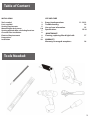
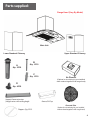
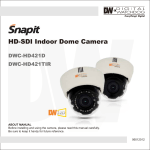
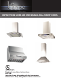
INSTRUCTIONS GUIDE AND USER MANUAL WALL MOUNT HOODS.
IMPORTANT:
Read and save these instructions.
NOTICE:
Installer: Leave this guide with the homeowner
Homeowner: Keep this guide for future reference
Important Safety Notice
Read all Instructions before Installing and operating this appliance
• The installation in this manual is intended for qualified installers, service technicians or persons with similar
qualified background. Installation and electrical wiring must be done by qualified professionals and in accordance with all applicable codes and standards, including fire-rated construction.
• DO NOT attempt to install this appliance yourself. Injury could result from installing the unit due to lack of
appropriate electrical and technical background.
• Range hood may have very sharp edges; please wear protective gloves if it is necessary to remove any parts
for installing, cleaning or servicing.
• Activating any switch ON before completing installation may cause ignition or an explosion.
• Due to the size and weight of this range hood, two people installation is recommended.
To reduce the risk of fire, electric shock, or injury to persons:
• For general ventilating use only. DO NOT use to exhaust hazardous or explosive materials and
vapors.
• The combustion air flow needed for safe operation of fuel-burning equipment may be affected by this unit’s
operation. Follow the heating equipment manufacturer’s guideline and safety standards such as those published by the National Fire Protection Association (NFPA), and the American Society of Heating, Refrigeration
and Air Conditioning Engineers (ASHRAE), and the local code authorities.
• Before servicing or cleaning unit, switch power OFF at service panel and lock service panel to prevent power
from being switched ON accidentally.
• Clean grease laden surfaces frequently. To reduce the risk of fire and to disperse air properly, make sure to
vent air outside. DO NOT vent exhaust into spaces between walls, crawl spaces, ceiling, attics or garages.
• Ducted fans MUST always be vented to the outdoors.
• Use only metal ductwork and this unit MUST be grounded.
• Sufficient air is needed for proper combustion and exhausting of gases through the duct to prevent back drafting.
• When cutting or drilling into wall or ceiling, be careful not to damage electrical wiring or other hid- den utilities.
• All electrical wiring must be properly installed, insulated and grounded.
• Old duct work should be cleaned or replaced if necessary to avoid the possibility of a grease fire.
• Check all joints on duct work to insure proper connection and all joints should be properly taped.
• Use this unit only in the manner intended by the manufacturer. If you have questions, contact the
vendor.
To reduce the risk of a stove top grease fire:
• Keep all fan, baffle, spaces, filter, grease tunnel, oil container and grease-laden surfaces clean. Grease
should not be allowed to accumulate on fan, baffle, spaces, filter, grease tunnel and oil container.
• Always turn range hood ON when cooking at high heat or when cooking flaming foods.
• Use high settings on cooking range only when necessary.
• Never leave surface units unattended at high settings. Boil over cause smoking and greasy spillovers
that may ignite. Heat oils slowly on low or medium settings.
• Clean ventilating fan frequently.
• Always use appropriate cookware and utensils size.
• Always use cookware appropriate for the size of the surface element.
1
Important Safety Notice
Read all Instructions before Installing and operating this appliance
To reduce the risk of injury to persons in the event of a stove top grease fire:
• SMOTHER FLAMES with a close-fitting lid, cookie sheet, or metal tray, then turn OFF the burner.
BE CAREFUL TO PREVENT BURNS. NEVER PICK UP A FLAMING PAN—you may be burned. KEEP FLAMMABLE OR COMBUSTIBLE MATERIAL AWAY FROM FLAMES. If the flames DO
NOT go out immediately, EVACUATE AND CALL THE FIRE DEPARTMENT or dial your local emergency
service immediately.
• DO NOT USE WATER, including wet dishcloths or towels — a violent steam explosion will result.
Use an extinguisher ONLY if:
You know you have a Class A, B, C extinguisher, and you already know how to operate it.
The fire is small and contained in the area where it is started.
The fire department is being called.
You can fight the fire with your back to an exit.
To reduce the risk of injury to persons in the event of a gas leaks:
• Extinguish any open flame.
• DO NOT turn on the range hood fan or any type of ventilator.
• DO NOT turn on the lights or any type of appliance.
• Open all doors and windows to disperse the gas. If you still smell gas, call the gas company and fire department, or dial your local emergency service immediately.
Your safety and the safety of others is very important. We have provided many important safety mes- sages in
this manual and on your appliance. Always read and obey all safety messages. All safety mes- sages will tell
you what the potential hazard is, tell you how to reduce the chance of injury, and tell you what can happen if the
instructions are not followed.
WARNING
This is the safety alert symbol. This symbol alerts you to potential hazards that can hurt you and others. All
safety messages will follow the safety alert symbol and the word “WARNING”.
The manufacturer and/or distributor/reseller declines all responsibility in the event of failure to observe the instructions given here for installation, maintenance and suitable use of the product.
The manufacturer and/or distributor/reseller further declines all responsibility for injury due to
negligence and the warranty of the unit automatically expires due to improper maintenance.
The manufacturer and/or distributor/reseller will not be held responsible for any damages to per- sonal
property or real estate or any bodily injuries whether caused directly or indirectly by the range
hood.
2
Table of Content
USE AND CARE
INSTALLATION
Tools needed.
Parts supplied.
Venting requirements.
Mount heights & clearance.
Venting methods & Re-calculating functions
Charcoal Filter Installation
Electrical Requierements
Preparations
Installation
3
4
5
5-6
7
8
8
9
10
Range hood operations
Troubleshooting.
Use and care information.
Specifications
11-12-13
14
15
15-16
MAINTENANCE
Cleaning, replacing filter & light bulb
17
WARRANTY
Warranty, Coverage & exceptions.
18
Tools Needed:
3
Parts supplied:
Range Hood (Vary By Model)
Main Unit
Lower Standard Chimney
Upper Standard Chimney
B
Qty: 1PCS
A
Qty: 2PCS
C
Qty: 1PCS
Air Diverter
(Optional re-circulating kit, pre-installed
when ordered together with range hood)
D
Qty: 4PCS
Support frame extension
(Length varies with ceiling heigh
Flappers Qty: 2PCS
Grease/Oil Cup
Charcoal filter
(Optional re-circulating kit, pre-installed
when ordered together with range hood)
4
Venting Requirements
• Vent system must terminate to the outside (roof
or side wall).
• DO NOT terminate the vent system in an at- tic
or other enclosed area.
• DO NOT use 4” (10.2 cm) laundry-type wall
caps.
• Use metal /aluminum vent only. Rigid metal
(Not Included).
aluminum vent is recommended.
• DO NOT use plastic vent.
•Always keep the duct clean to ensure proper
airflow.
• Calculate the following figures before
installation:
1.Distance from the floor to the ceiling.
2.Distance between the floor to the countertop/stove (Usually 36 Inches).
3.Distance between the countertop/stove to the
range hood.
We recommend (25.5’ to 27 1/2’ Inches).
4. Height of hood and duct cover.
For the most efficient & quiet operation:
Height & Clearance
Maximum* ceiling clearance 106” at 27.5” hood
mounting height above
countertop/stove (may vary
with different model).
Chimney extensions
available for higher ceiling.
Support
Structure
Standard
Upper
Chimney
Extension available*
Support Structure
Standard
Lower
Chimney
Extension available*
Range hood
Min: 25.5”
Max: 27.5”
Max*: 101”
• It is recommended that the range hood be
vented vertically through the roof through 6”
(15.24 cm) or bigger round metal / aluminum
vent work.
• The size of the vent should be uniform.
• Use no more than two 90° elbows.
• Make sure there is a minimum of 24” (61 cm)
of straight vent between the elbows if more than
one elbow is used.
• DO NOT install two elbows together.
The length of vent system and number of
elbows should be kept to a minimum to pro- vide
efficient performance.
36” base
• The vent system must have a damper. If roof
or wall cap has a damper, DO NOT use damper
(if supplied) on top of the range hood.
• Use silver tape or duct tape to seal all joints in
the vent system.
• Use caulking to seal exterior wall or roof opening around the cap.
5
Important
• A minimum of 6” round (standard for this range hood) or 3-1/4 x 10” rectangular duct (purchased separately) must be used to maintain maximum airflow efficiency.
• Flexible 6” round duct, always use rigid type metal/aluminum ducts if available to maximize airflow
when connecting to provided duct.
• Please use Duct Run Calculation below to compute the total available duct run when using elbows,
transitions and caps.
• ALWAYS, when possible, reduce the number or transitions and turns. If long duct run is required,
increase duct size from 6” to 7” or 8”. If a reducer is used, install a long reducer instead of a pancake
reducer.
• Reducing duct size will restrict airflow and decrease airflow, thus reduce duct size as far away from
opening as possible.
• If turns or transitions are required: Install as far away from opening and as far apart, between 2, as possible.
• Minimum mount height between stove top to hood bottom should be no less than
28-inch*.
• Maximum mount height between stove top to hood bottom should be no higher than 31-inch*.
• It is important to install the hood at the proper mounting height. Hoods mounted too low could result in
heat damage and fire hazard; while hoods mounted too high will be hard to reach and will loose its
performance and efficiency.
• If available, also refer to stove top manufacturer’s height clearance requirements and recommended
hood mounting height above range.
* Due to different ceiling height configurations, recommended height may not be applicable.
Minimum Duct Size:
• Round - 6” minimum
• Rectangular - 3-1/4 x 10” minimum (requires a 6” to 3-1/4x10” adaptor, not supplied)
To calculate the length of the system you need, deduct the equivalent feet for each vent piece used in
the system from the recommended maximum duct run.
Duct Run Calculation:
Recommended maximum run
R6” or 3-1/4 x 10” duct
30 ft
Vent piece deduction
Each 90º elbow used
9 ft
Each 45º elbow used
5 ft
Each 6” to 3/14 x 10” transition used
7 ft
Side wall cap with damper
0 ft
Roof cap
0 ft
Duct Run Calculation example:
One roof cap, one 90º elbow, and one 45º elbow
used: 9ft + 5ft = 14 ft used.
Deduct 14 ft from 30ft, 16ft maximum available for
straight duct run. If no elbows are used, maximum
run is 30 ft (recommended).
6
Venting Methods:
This range hood is factory set for venting through the roof or wall.
• Vent work can terminate either through the roof or wall. To vent through a wall, a 90°
elbow is needed.
IMPORTANT:
• NEVER exhaust air or terminate duct work into spaces between walls, crawl spaces,
ceiling, attics or garages. All exhaust must be ducted to the outside.
• Use metal/aluminum duct work only.
• Fasten all connections with sheet metal screws and tape all joints with certified Silver
Tape or Duct Tape.
• Use caulking to seal exterior wall or roof opening around the cap. ( Not included)
Option 2: Horizontal wall venting
Option 1: Vertical roof
venting
Roof cap
Side wall cap
Re-Circulating Function Methods:
Re-circulating function is intended for applications where an exhaust duct work is not possible to be
installed. When converted, the hood functions as a purifying hood rather than an exhaust hood. Fumes
and exhaust from cooking is drawn and filtered by a set of charcoal filters. The air is then purified and
re-circulated back within the home.
• We recommend to ALWAYS exhaust air outside of the home by employing existing or installing new
duct work, if possible. Only when the exhaust option is not possible should you recourse to converting
the hood into a purifying unit.
• When converted to be a “purifying” unit, a charcoal filter is required in addition to its standard aluminum
filter set. Available online only!!!. The standard aluminum filters are intended to capture residue from
cooking, the optional charcoal filters help to purify fumes exhausted from cooking.
7
Charcoal Filter Installation
NOTE: The charcoal filter or filters are required when using the LeCappe hood as a purifying unit
only if you purchased the range hood with re-circulating kit from us.
1. Remove aluminum filters on hood.
2. Position the charcoal filter or filters depending on model, onto each side of the motor and turn
until it locks. Re-install aluminum filters.
3. Charcoal filters must be replaced after 120 hours of use (or approximately every 2 to 3 months
based on the average of 1 to 2 hours of daily cooking time). Available online only at
www.lecappe.com
Electrical Requirements
It is the customer’s responsibility:
• To contact a qualified electrical installer.
• To assure that the electrical installation is adequate and in conformance with National Electrical Code, ANSI/
NFPA 70 — latest edition*, or CSA Standards C22. 1-94, Canadian Electrical Code, Part 1 and C22. 2 No.
0-M91 - latest edition** and all local codes and ordinances.
If codes permit and a separate ground wire is used, it is recommended that a qualified electrician determine that
the ground path is adequate.
A 120-Volt, 60 Hz, AC-only (USA & Canada standard), fused electrical supply is required on a separate 15-amp
circuit, fused on both sides of the line.
DO NOT ground to a gas pipe.
Check with a qualified electrician if you are not sure that the range hood is properly grounded.
DO NOT have a fuse in the neutral or ground circuit.
IMPORTANT: Save this Installation Guide for electrical inspector’s use. The range hood must be connected
with appropriate wire/plug only.The range hood should be connected directly to the fused disconnect (or circuit
breaker) box through flexible armored or non-metallic sheathed copper cable. A U.L. - or C.S.A. - listed strain
relief must be provided at each end of the power supply cable.
Wire sizes must conform to the requirements of the National Electrical Code ANSI/NFPA 70 — latest edition*,
or CSA Standards C22.1-94, Canadian Electrical Code Part 1 and C22. 2 No. 0-M91 - latest edition** and all
local codes and ordinances. A U.L. - or C.S.A. - listed conduit connector must be provided at each end of the
power supply cable (at the range hood and at the junction box).
Copies of the standards listed may be obtained
from:
National Fire Protection Association Batterymarch Park Quincy, Massachusetts 02269
** CSA International
8501 East Pleasant Valley Road Cleveland, Ohio 44131-5575
8
Preparations
NOTE: To avoid damage to your hood, prevent debris from entering the vent opening.
1. Carefully remove the white plastic protective coat from the chimney covers and range hood
2. Determine and mark the center line on the ceiling where the range hood will be installed. Make sure
there is proper clearance within the ceiling or wall for exhaust vent.
3. Due to the weight and size of this unit, please make sure that the support system or framework
being used is stable and secure in the wall.
4. Put a thick, protective covering over counter top, cook top or range to protect from damage or dirt.
Remove any hazardous objects around the area when installing.
5. Mark the locations of the support mounting bracket holes, vent cutout (if used) and power supply
cable cutout on the ceiling. Use drill and saber saw or keyhole saw to cut openings for power supply
cable and vent (see Venting requirements and Electrical requirements.
6. If venting to the outside installs vent system (see Venting Methods). Use caulking to seal exterior
wall or roof openings.
7. Disconnect main electrical supply, prepare and run electrical wiring through ceiling or wall.
8. Leave approximately 12” of electrical cord hanging from the ceiling. Do not restore power until
wiring is completed.
9. Disconnect power cord, remove the aluminum filter by pressing on the latch gently pull the aluminum filter toward the direction of dashed arrow as shown in Figure 1.
10. Remove the grease cup by sliding it sideway , see Figure 2 for location of the grease cup.
11. Set aside the aluminum filters and grease cup until the range hood is properly installed.
WARNING
Severe Injury Rotating fan
can cause severe injury.
Stay clear of fan when
motor is running.
9
Installation
27.5”
1) Position the range hood on the center of cooking stove wall. For best results, the mounting height of the
range hood should be 65-75cm (25"-30") above the top of the range. Mark the position of the holes, which
need to be drilled in order to mount the range hood.
2) According to marks, drill two holes appropriate for heavy duty wall anchors and screws (not included).
Mount the range hood on the wall with the two screws and anchors and tighten.
3) Install the one-way valve on top of the range hood and assemble the exhaust pipe and decorative cover.
4) Affix the decorative cover with two M4 tapping screws on the hood body.
5) Make sure all switches are off and then insert the electrical plug into an outlet.
Technical Parameters
ITEM
Rated Voltage
Rated frequency
Motor input power
Lamp power
Air volume
Air pressure
Noise level
Air output diameter
unit
V
Hz
W
W
m3/min
Pa
dB(A)
mm
parameter
110
60
198
≤2X20
9.5~15
>160
<70
150
10
Range
Hood
Controls
Range
HoodOperations
Opeations & Controls
Control Panel Layout and Buttons Configurations for models: Grecia, Paris, Venice Pro.
11
Range Hood Operations Controls
Control Panel Layout and Buttons Configurations for models: Moon & Viena.
12
Range Hood Operations Controls
Control Panel Layout and Buttons Configurations for models: Messina & Athenas
(See your specific model)
13
Troubleshooting
1. If the range hood or halogen light does not operate
after installation:
• Check if the range hood has been plugged in, make
sure that all power has been turned back ON, fused
not blown and all electrical wiring are properly
connected.
• Swap out light assembly to working ones to determine whether it is caused by defective bulbs.
2. The range hood vibrates when the blower is on:
• The range hood might not have been secured
Properly on to the ceiling or wall. Check with your
installer
3. The blower or fan seems weak:
• Check that the duct sized used is at least 6” or 3-1/4
x 10”. Range hood WILL NOT function efficiently with
insufficient duct size. For example: 7” duct over 6”
hole and loosely secured.
• Check if duct is clogged or if damper unit (half-circular flapper) is not installed correctly or opening
properly. A tight mesh on a side wall cap unit might
also cause restriction to the air flow.
4. The lights work but the blower is not spinning at all,
is stuck or is rattling.
• The blower might be jammed or scraping the
bottom due to shipping damage. Please contact us
immediately.
5. The hood is not venting out properly:
• Make sure the distance between the stove top and
the
bottom of the hood is within* 28” and 31” in
distance. *Due to different ceiling height configurations, recommended height may not be applicable.
Reduce the number of elbows and length of duct
work. Check if all joints are properly connected,
sealed, and taped.
Make sure the power is on high speed for heavy
cooking.
6. Purpose of the slots/holes/openings near the top of
the upper chimney:
• These slots/holes/openings are used to exhaust
cleaned air with optional re-circulating kit. If you did
not install one, you do not need them.
14
Use and Care Information
Operations:
• Read and understand all instructions and warnings in this manual before operating the appliance.
Save theseinstructions for future reference.
• Always leave safety grills and filters in place. Without these components, operating blowers could catch on
to hair, fingers and loose clothing.
• NEVER dispose cigarette ashes, ignitable substances, or any foreign objects into blowers.
• NEVER leave cooking unattended. When frying, oil in the pan can easily overheat and catch fire. The risk
of self combustion is higher when the oil has been used several times.
• NEVER cook on “open” flames under the range hood. Check deep-fryers during use: Superheated oil may
be flammable.
Cleaning:
• The saturation of greasy residue in the blower and filters may cause increased inflammability. Keep unit
clean and free of grease and residue build-up at all times to prevent possible fires.
• Filters must be cleaned periodically and free from accumulation of cooking residue (see cleaning instructions on Page 17). Old and worn filters must be replaced immediately.
• DO NOT operate blowers when filters are removed. Never disassemble parts to clean without proper
instruc- tions. Disassembly is recommended to be performed by qualified personnel only. Read and understand all instructions and warnings in this manual before proceeding.
Specifications
Specifications*:
Body
Power Rating
General Input Power
Motor Input Power
Motor Revolution
Levels Of Speed Control
Maximum Airflow
Air Pressure
Noise Level (dB / sone)
Motor Type
Fan Type
Control Type
Filtration Type
Illumination
Venting Size
Stainless Steel / Tempered Glass
120V/60Hz (USA & Canada standard)
358 W (218W + 4x35W)
218 W
600 RPM (±10%) to 1800 RPM (±10%)
3 Levels
600 CFM
320 pa
Approximately 23 / 0.3 to 68 / 7.0 (Lowest to highest Speed)
Dual Chamber Ultra Quiet
Dual Centrifugal / Sirocco
Dual Electronic Control Panels with LCD Display
Aluminum Filter with Reversible Handle
4 X 20 W hallogen Lights
Top, 6 inches Round
*Subject to change without notice, please contact your local reseller for details.
15
Specifications
For Wall PRO Venice
Specifications*:
Body
Stainless Steel / Tempered Glass
Power Rating
General Input Power
120V/60Hz (USA & Canada standard)
720 W (380W + 2x20W)
Motor Input Power
Motor Revolution
218 W
600 RPM (±10%) to 1800 RPM (±10%)
Levels Of Speed Control
Maximum Airflow
3 Levels
1200 CFM
Air Pressure
320 pa
Noise Level (dB / sone)
Motor Type
Approximately 23 / 0.3 to 68 / 7.0 (Lowest to highest Speed)
Dual Chamber Ultra Quiet
Fan Type
Control Type
Dual Centrifugal / Sirocco
Dual Electronic Control Panels with LCD Display
Filtration Type
Illumination
Venting Size
Aluminum Filter with Reversible Handle
2 X 20 Halogen Lamp Lights/2 heat lamps.
Top, 10 inches Round
For optimal operation, clean range hood and all baffle/spacer/filter/grease tunnel/oil container regularly.
Regular care will help preserve the appearance of the range hood.
Cleaning Exterior surfaces:
• Clean periodically with hot soapy water and clean cotton cloth. Do not use corrosive or abrasive detergent
(e.g. Comet Power Scruv®, EZ-Off® oven cleaner), or steel wool/scoring pads, which will scratch and
damage the stainless steel surface. For heavier soil use liquid degrease such as “Formula 409®” or
“Fantastic®” brand cleaner.
• If hood looks splotchy (stainless steel hood), use a stainless steel cleaner to clean the surface of the hood.
Avoid getting cleaning solution onto or into the control panel. Follow directions of the stainless steel cleaner.
CAUTION: Do not leave on too long as this may cause damage to hood finish. Use soft towel to wipe off the
cleaning solution, gently rub off any stubborn spots. Use dry soft towel to dry the hood.
• After cleaning, you may use non abrasive stainless steel polish such as 3M® or ZEP®, to polish and buff
out the stainless luster and grain. Always scrub lightly, with clean cotton cloth, and with the grain.
• DO NOT allow deposits to accumulate or remain on the hood.
• DO NOT use ordinary steel wool or steel brushes. Small bits of steel may adhere to the surface and cause
rusting.
• DO NOT allow salt solutions, disinfectants, bleaches, or cleaning compounds to remain in contact with
stainless steel for extended periods. Many of these compounds contain chemicals, which may be harmful.
Rinse with water after exposure and wipe dry with a clean cloth.
16
Cleaning Aluminum Grease Filter / Stainless Steel Filter less Grill
WARNING
• Failure to observe the instructions on cleaning the unit and changing the filters could cause a fire
hazard. You are therefore strongly recommended to follow these instructions.
• The manufacturer declines all responsibility for any damage to the motor or any fire damage linked to
inappropriate maintenance or failure to observe the above safety recommendations.
Changing The Light Bulb
• Disconnect the cooker hood from the mains supply.
• Remove the lamp cover, use a screw driver as a lever. Fig. 5.
• Replace the old bulb with a new one of the same type.
• Refit the lamp cover.
• If the light does not come on, make sure the bulb has been inserted in correctly before contacting your
local AEG Service Force Centre.
Fig. 5.
17
Le Cappe One Year Limited Warranty:
Please provide an original dated proof of purchase (sales receipt / invoice) in order to obtain service under
warranty.
One Year Parts warranty:
For one year from the date of original purchase, your local reseller will provide free of charge, nonconsumable replacement parts or components that failed due to manufacturing defects. Subject to the
conditions and limitations set forth below, your local reseller will, at its option, either repair or replace any
part of its products that prove defective by reason of improper workmanship or materials. Repaired parts or
replacement products will be provided by your local reseller on an exchange basis, and will be either new or
refurbished to be functionally equivalent to new. The consumer is responsible for all shipping costs. Consumable parts not covered by this warranty include but not limited to: Light bulbs, metal, aluminum and
charcoal filters.
Who is covered:
This warranty is extended to the original purchaser for products purchased for ordinary home use.
This Warranty Will Be Voided When:
Product damaged through negligence, improper installation, accident, abuse, misuse, natural disaster,
insufficient or excessive electrical supply, abnormal mechanical or environmental conditions, or any unauthorized disassembly, repair, modification, or failure to follow installation instructions.
When product is used commercially, or other than its intended purpose.
Damaged, because of improper connection with equipment of other manufacturers. Repaired or modified by
anyone other than your local reseller’s authorized agents. This limited warranty also does not apply to any
product on which the original identification information has been altered, obliterated or removed, has not
been handled or packaged correctly or has been sold as second-hand.
What is Not Covered:
Consumable parts such as light bulbs, metal and charcoal filters. The natural wear of finish, and wear due to
improper maintenance, use of corrosive and abrasive cleaning products, pads, and oven cleaner products.
Chips, dents or cracks due to abuse, misuse, freight damage, or improper installation.
Damage of product caused by accident, fire, floods or act of God.
The manufacturer and/or distributor/reseller is not liable for, and does not cover under warranty, any loss of
properties or any costs associated with removing, servicing, installing, or determining the source of problems
with this product.
This warranty is valid in the country of the original purchase at retail. It is non-transferable and applies only
to the original purchaser and does not extend to subsequent owners of this product. Any applicable implied
warranties, including the warranty of merchantability, are limited in duration to a period of express warranty
as provided herein beginning with the date of original purchase at retail and, no warranties, whether express
or implied, shall apply to this product thereafter.
To obtain warranty service, you may contact your local reseller from which you purchased this product.
Please confirm the terms of your local reseller’s policies prior to contacting. Typically, you must include
product identification information, including model number and serial number with a detailed description of
the problem you are experiencing. You must include proof of the date of the original retail purchase as
evidence that the product is within the applicable warranty period.
The information in this document is subject to change without notice, please contact your local reseller for updated details.
18