1
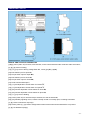
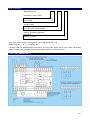
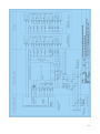
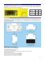
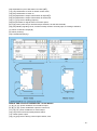
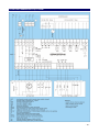
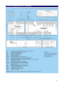
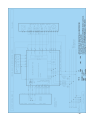
ELECTRIC ACTUATORS CONTROLLER SERVOSTER-04 & SERVOSTER-05 Technical characteristics and user’s manual © Industrial Automatics Enterprise INTEC LTD.CO Bacciarellego 54, 51-649 Wrocław, POLAND Tel. 048 71 348 18 18 Fax 048 71 348 15 15 www.intec.com.pl ver. 2011 Table of Contents SERVOSTER-04 SERVODRIVER ............................................................................................ - 3 PURPOSE AND FEATURES ................................................................................................................................... - 3 CONSTRUCTION AND INSTALLATION ............................................................................................................. - 3 PERFORMANCE ...................................................................................................................................................... - 3 INSTRUCTIONS FOR DESIGNERS ....................................................................................................................... - 4 INSTALLATION ENVIRONMENT ........................................................................................................................ - 5 LAUNCHING THE SERVODRIVER ...................................................................................................................... - 5 MAINTENANCE ...................................................................................................................................................... - 5 DIMENSIONAL SKETCH ....................................................................................................................................... - 6 TECHNICAL PARAMETERS ................................................................................................................................. - 7 HOW TO ORDER? ................................................................................................................................................... - 8 FLOW CHART SERVOSTER-04 ............................................................................................................................ - 8 - SERVOSTER-05 SERVODRIVER .......................................................................................... - 10 PURPOSE AND FEATURES ................................................................................................................................. - 10 CONSTRUCTION AND INSTALLATION ........................................................................................................... - 10 PERFORMANCE .................................................................................................................................................... - 11 INSTRUCTIONS FOR DESIGNERS ..................................................................................................................... - 12 INSTALLATION ENVIRONMENT ...................................................................................................................... - 13 LAUNCHING THE SERVODRIVER .................................................................................................................... - 13 SETTING OVERCURRENT PROTECTION IN SERVOSTER-05-7.5 ................................................................ - 13 ON-OFF SWITCH OF DIRECTIONAL INTERLOCK ......................................................................................... - 14 MAINTENANCE .................................................................................................................................................... - 14 TECHNICAL PARAMETERS ............................................................................................................................... - 16 HOW TO ORDER? ................................................................................................................................................. - 17 FLOW CHART SERVOSTER-05 up to 2.5kW ...................................................................................................... - 18 FLOW CHART SERVOSTER-05 up to 7.5kW ...................................................................................................... - 19 - -2- SERVOSTER-04 SERVODRIVER PURPOSE AND FEATURES SERVOSTER-04 is an electronic integrated servodriver dedicated to control actuators working in modulating duty. It performs contactless remote control of electric drives with three-phase electric motors up to 2.5 kW. It supports main logic and linking features required for regulatory servomotor: contactless switching and reversing service duty of servomotor’s engine during heavy-duty action (switching in zero point of mains voltage), remote motor’s slow down with energy recovery, three-points control duty directly from PLC driver, control panel or system, automatic servomotor stoppage in ultimate positions, automatic servomotor stoppage in absence of electric standby, co-operation with limit and torque switches and motor’s thermostat, duplication of limit switches, LED signaling of servomotor’s field state and electric standby, internal protection against short circuits and phase’s fading. CONSTRUCTION AND INSTALLATION Driver has on-rail case made of Noryl 94VO, ready for fitting on typical DIN 35 mm rail. The equipment has to 2 be installed in control box or any other indoor place. Maximal size of attached wires is 2.5 mm . On both ends of case are multiple connectors WAGO-type with input and output specifications. Figure (page 6) gives overall view of the driver and its dimensions. Front panel consists of: variable slow down time control knob with gauge 0÷90 ms, signaling LEDs: o single blue for Standby, o single green for All Phases, o double green (So and Sz) for direction of control, o single red for Fuses’ Check-up, o quadruple green (Ko, Kz, Mo, Mz) for position of limit and torque switches of servomotor o single red (T) for position of motor’s thermostat. SERVOSTER-04 has two versions: for 1.5kW and 2.5kW motor. The latter has built-in radiator (assembled between servodriver and rail attachment handles). The radiator has its own PE grip. PERFORMANCE SERVOSTER-04 control operations base on the following signals: Remote control, 24V DC, free polarization, current consumption 12mA: remote control for Open (So) – voltage supplied on [13] and [14], remote control for Close (Sz) – voltage supplied on [15] and [14]. Main conditions for remote control, 230V AC, current consumption 12mA: normally closed limit and torque switches–voltage supplied on [23, 24, 25, 26] shorted motor’s thermostat – voltage supplied on [27]. Additional conditions for remote control: presence of feeding voltage 230V AC on [2], presence of working voltage 400V AC on [4, 5, 6]. Electric standby fails when: one or more phases of working voltage fade, fuse blew out, feeding voltage disappeared, motor’s thermostat had ran, internal self-test fails. -3- SERVOSTER-04 supports main logic features typical of classic contactor-rely field, as well additional ones. These are: three-points control duty, passing over the start impulses shorter than 60ms, switching on and off in zero point of mains voltage (what eliminates an overvoltage), slowing down appears automatically after switch off the control signal. Slow down performed by servodriver is very effective one, thanks to electric brake function with energy recovery. The motor slows down dynamically; when it stops the brake features are aborted. Electric brake function can be excluded by turning variable slow down time control knob to null position. SERVOSTER-04 checks its fuses and the presence of all power phases. Single red LED (Fuses’ Check-up) indicates possible fuses’ blow out; simultaneously goes out the blue one (Standby). Fading of one or more power phases lead to switching off two LEDs: single green (All Phases) and blue one (Standby). Whichever of mentioned above appears, the motor control duty will be aborted and Standby LED will indicate the servodriver’s off duty state. SERVOSTER-04 checks limit switches of servomotor. If one of them appears open, the proper LED will go out and the motor slows down until full stoppage. Driving in this direction will be blocked and duplicate relays will turn on. Running of the motor’s thermostat results in flash of red LED (marked T), going out of blue one (Standby), motor’s stoppage, and lock of driving in both directions. INSTRUCTIONS FOR DESIGNERS ATTENTION! The manual refers to 230 and 400V AC. However, SERVOSTER circuits also work with 220 and 380V AC. Servodriver has to be connected to the mains via automatic switches. Single-phase switch (up to 6A) protects both internal circuits of SERVOSTER and of limit switches. For engine’s feeding, the motor-switch is needed: up to 4A in case of 1.5 kW motor, and up to 6.3A in case of 2.5 kW one. SERVOSTER-04 has own internal 10A fuses. Correct regulation of motor-switch results in selective action of fuses. In case of short circuit within motor’s feeding circuit, as first the motor-switch will do the job. Total length of wires leading to servomotor cannot exceed 300 m (wire size 1.5 mm2). Driver has own varistore protection against overvoltage. However, when these phenomena are of extremely high value (e.g. resulting from lightning), mentioned protection works as fuses and SERVOSTER will stop working. Thus, it is strongly recommended to install external overvoltage protection of C or D characteristics, assembled on power supply of control boxes and between SERVOSTERs and solenoid contactors’ controlled areas. Driving voltage is 24V DC, freely polarized. Thanks to that, SERVOSTER-04 properly interacts both with controllers with common (shared) plus or minus output voltage. Limit and torque servomotor’s switches can be arrange in serial, parallel, or mixed connections (see flow charts). As inputs [23] and [25] are duplicated (with negation), different arrangement of switches allows for changeable duplication. Parallel and mixed connection will result only in duplication of limit switches’ contacts, serial one will give contacts’ product. Changing inputs: Ko with Mo and Kz with Mz gives duplication of torque switches instead of limit ones. Duplication of limit switches acts along two pathways with galvanic insulation. Thus, duplicated contacts can be used in block and security systems working on different voltages. ATTENTION! In case of lack of power or servodriver’s failure, state of contacts duplicating limit switches may differ of state of switches themselves. If duplications are used in block and security systems, these must strictly control the SERVOSTER-04 standby contact. Alternatively, SERVOSTER-05 can be applied, as it leads to duplications regardless of own standby state. Control voltage of 24V DC on SERVOSTER-04 inputs is galvanically insulated from other voltage levels present within servodriver. Thus, the direct control from controller card is recommended. Duplications’ contacts as well as electric standby contact can be–on demand–shunted with resistors of line supervision (40÷47kΩ, up to 60V DC). Standby contact can be both normally open or normally closed type. On special demand, servodrivers can be adjusted for singleor double-phase servomotors and different voltage levels. -4- If electromechanical brake is built in actuator, it is of crucial importance to plug it directly to terminal [10] of servodriver. Basically, SERVOSTER-04 is intended for modulating duty actuator, where rarely local control is applied and signal of three-points control duty is not held up. However, there are numerous applications of mentioned servodriver to control on-off drives. In such cases local control of the drive, as well as control signals’ hold up have to be guided by external automatics’ system. This problem eliminates SERVOSTER-05 servodrive. In doubtful situations please do not hesitate to contact with INTEC Unlimited Company. INSTALLATION ENVIRONMENT SERVOSTER-04 should be installed indoors. However, it is not allowed to fit the appliance in places running the risk of explosion, in corrosive and dusty environment, and where relative humidity exceeds 80%. LAUNCHING THE SERVODRIVER Before start, it is necessary to turn variable slow down time control knob to null position. Next comes connection according to the application diagram. When it is completed, it is allowed to plug servodriver in (feeding voltage of 230V AC, working voltage of 3 x 400V AC). On control panel would shine LEDs: blue, indicating Standby, green for All Phases, quadruple green for Ko, Mo, Kz, and Mz. Beforehand, it is essential to feed control inputs So and Sz with 24V voltage and examine whether the direction of motor’s rotation is in agreement with directions of limit switches. If it is not, polarization has to be changed. Otherwise, lack of compatibility will result in servomotor’s and servodriver’s damage. Position of variable slow down time control knob should allow not loaded motor to make 3–5 turns before full stoppage. Slow down adjustment is of stepwise mode, working in 15ms’ intervals. In fact, for 1500 r.p.m. motors braking time of 15ms is sufficient, for 3000 r.p.m. ones–of 30ms. MAINTENANCE SERVOSTER-04 is maintenance-free appliance. In case of fuses’ blow out, their replacement calls for fully trained maintenance worker. The servodriver must be disassembled and only fuses supplied by its manufacturer are approved. -5- DIMENSIONAL SKETCH INPUTS’ AND OUTPUTS’ DESCRIPTION [1]&[2]–power (230V AC) for driver, limit switches, motor’s thermostat and other receivers within servodriver, [4], [5], [6]–motor’s feeding, [13], [14], [15]–motor’s driving voltage #24V DC, 12mA ([13] So, [15] Sz), [23]–limit switch input for Open Ko, [24]–torque switch input for Open Mo, [25]–limit switch input for Close Kz, [26]–torque switch input for Close Mz, [27]–motor’s thermostat input T, [16], [17]–first duplication of limit switch for Close K’z’, [18], [17]–first duplication of limit switch for Open K’o’, [19], [20]–second duplication of limit switch for Close Kz, [21], [20]–second duplication of limit switch for Open Ko, [10], [11], [12]–motor’s feeding, [22]–power (230V AC) for limit and torque switches, as well as thermostat, [29], [30]–Standby signaling circuit; contact normally closed or normally open, according to demand [7], [8]–mains’ neutral wire output (N) [28]–mains’ phase (L); grip used to bridge thermostat’s terminal when thermostat itself is not present. [3], [9]–not attributed (empty) -6- TECHNICAL PARAMETERS Power voltage: 230V AC, range -15% ÷ +10%. Working voltage: 3 x 400V AC. Own power consumption: up to 7VA. Power loss in current circuit: up to 5W. Residual current: 0.01mA at 25°C. External protection: o three-phase motor-switch, series M250 by FAEL recommended: 4A for 1.5kW motor, 6.3A for 2.5kW motor, o 6A single-phase fast automatic switch, o collective overvoltage protection of C or D characteristics. Power of controlled electric engine: up to 2.5kW Internal protection : fast 10A fuses. Driving voltage: 24V DC, freely polarized, with galvanic insulation from mains and other input/output pathways. Current intensity of driving inputs: 12mA AC. Output voltage for limit switches and motor’s thermostat: 230V AC. Current intensity from limit switches and motor’s thermostat: 12mA AC Activation voltage of inputs of limit switches and thermostat: at least 160V AC. Deactivation voltage of inputs of limit switches and thermostat: maximum 120V AC. Operating temperature: 0÷50°C. Duplication of limit switches: 2 pairs of separate contacts, each with shared point. Contact’s load: 230V AC/DC, 1A. 2 Maximal wire size: 2.5 mm . Signaling: o single blue LED for Standby + contact 230V AC/DC, 1A, o single green LED for All Phases, o double green LED (So and Sz) for direction of control check-up, o single red for Fuses’ control, o quadruple green LED (Ko, Kz, Mo, Mz) for position of limit and torque switches of servomotor o single red (T) for position of motor’s thermostat. Motor’s slow down duration: stepwise, 0÷90ms. Noise level: in accordance with PN-EN 61000-6-4:2008. Resistance to noise: in accordance with PN-EN 61000-6-2:2008. Logic and linking features: contactless switching and reversing service duty of servomotor’s engine during heavy duty action, remote motor’s slow down, co-operation with limit and torque switches and motor’s thermostat, duplication of limit switches, verification of feeding, fuses’ check-up. Acceptable start impulses: not shorter than 60ms. 2 Total length of wires leading to servomotor: maximum 300 m with wire size of 1.5 mm . -7- HOW TO ORDER? SERVOSTER - 04 - X.X - X - X servomotor’s engine power up to 1,5 kW up to 2,5 kW 1.5 2.5 standby contact normally closed in standby mode normally open in standby mode 0 1 resistors of a line’s supervision not present present (40–47kΩ) 0 2 Order must consist of name of an appliance and coded specification, e.g.: SERVOSTER-04 – 1.5 – 0 – 2, quantity: 50 The above reads as: SERVOSTER-04 servodriver for motors with electric power up to 1.5kW, with standby contact normally open in standby mode and fitted with resistors of a line supervision. FLOW CHART SERVOSTER-04 -8- -9- SERVOSTER-05 SERVODRIVER PURPOSE AND FEATURES Servoster-05 is an all-purpose electronic servodriver dedicated to control actuators working in modulating mode, both executing regulatory and on-off tasks. It performs contactless remote control of electric drives with three-phase electric motors up to 7.5kW (9kW). It supports main logic and linking features required for regulatory and controlling servomotor: contactless switching and reversing service duty of servomotor’s engine during heavy-duty action, remote motor’s slow down with energy recovery, three-points control duty directly from PLC driver, control panel or system, automatic servomotor stoppage in ultimate positions, automatic servomotor stoppage in absence of electric standby, co-operation with limit and torque switches and motor’s thermostat, duplication of limit switches, duplication of regulatory state and working mode, control signals’ hold up until drive reaches extreme position, hold up drive’s lock at terminal stop until reverse control signal appears, this feature me by switch on or off interaction with control panel or local control box, servicing of emergency stop button and additional block systems, LED signaling of servomotor’s field state and electric standby, internal protection against short circuits and phase’s fading. CONSTRUCTION AND INSTALLATION Driver has on-rail case made of Noryl 94VO, ready for fitting on typical DIN 35 mm rail. The equipment has to be installed in control box or any other indoor place. Maximal size of attached wires for working voltage 2 2 (3 x 400V AC) is 2.5 mm for SERVOSTER 1,5 and 2,5 or 6 mm for SERVOSTER 7,5 ; for all other 2 connections 1.5 mm is sufficient. On both ends of case are multiple connectors WAGO-type with input and output specifications. Figure (page 17) gives overall view of the driver and its dimensions. Front panel consists of: variable slow down time control knob with gauge 0÷90 ms, signaling LEDs: o single blue for Standby (GE), o single green for All Phases, o double green (So and Sz) for direction of remote control, o single red for Fuses’ Check-up, o single green for remote control’s hold up (PDT), o single green for confirmation of motor’s control activation (ST), o single red for activation of motor’s remote control mode (Z), o double green for local control (SOM and SZM), o single green for local stoppage of servomotor’s action (STOP), o single green (of signaling type) for check-up of remote control driving voltage (UW), o quadruple green for products (K&M) of limit and torque switches, both for Open and Close directions, o single red for signaling of temporary directional interlock of control, until reverse driving impulse appears (Locked), o double green for duplication of servomotor’s limit switches (K’o, K’z), o single red (T) for motor’s thermostat action. SERVOSTER-05 has three versions: 1.5 for 1.5kW actuator working in both modulating and open-closed duty. 2.5 for 2.5kW actuator working in both modulating and open-closed duty. (with radiator) 7.5 for 7.5kW actuator working in modulating duty and for 9.0kW actuator working in open-closed duty. (made as two units, master module and slave/power module). - 10 - PERFORMANCE SERVOSTER-05 control operations base on the following signals: Remote control, input signals, 24V DC, free polarization, current consumption 12mA: remote control for Open (So)–voltage supplied on [13] and [16], remote control for Close (Sz)–voltage supplied on [15] and [16], control signals’ hold up until drive reaches extreme position (PDT)–voltage supplied on [14] and [16], Main conditions for remote control, 230V AC, current consumption 12mA: STOP signaling terminated–live current on [31], switching to remote control mode (Z) with simultaneous ceasing of local control–live current on [33] normally closed limit and torque switches–voltage supplied on [26] and [27] shorted motor’s thermostat–live current on [25]. Additional conditions for remote control: presence of feeding voltage 230V AC on [2] and [3]; both emergency stoppage and additional block systems are deactivated, presence of working voltage 400V AC on [4, 5, 6], servodriver must be in Standby mode, an absence of directional interlocks. Local control, input signals, 230V AC, current consumption 12mA: local control for Open (SOM)–voltage supplied on [30], local control for Close (SZM)–voltage supplied on [32]. Main conditions for local control: STOP signaling terminated–live current on [31], switching to local control mode (M) with simultaneous ceasing of remote control–no voltage present on [33]. Additional conditions for local control: the same as for remote control (see above). Electric standby fails when: one or more phases of working voltage fade, fuse blew out, feeding voltage disappeared, also after emergency stoppage (STOP AW) and additional block systems (Bd) came to action, motor’s thermostat had ran, So and Sz signals had appeared for longer than 1s, simultaneously had appeared products of Ko, Mo, Kz, and Mz for over 1s duration, internal self-test fails. SERVOSTER-05 supports all logic and linking features required for regulatory and controlling servomotor. These are: three-points control duty, passing over the start impulses shorter than 60ms, switching on and off in zero point of mains voltage (what eliminates an overvoltage), slowing down appears automatically after switch off the control signal. Slow down performed by servodriver is very effective one, thanks to electric brake function with energy recovery. The motor slows down dynamically; when it stops the brake features are aborted. Electric brake function can be excluded by turning variable slow down time control knob to null position. SERVOSTER-05 checks limit and torque switches of servomotor. If one of them appears open, the proper LED will go out and the motor slows down until full stoppage. Driving in this direction will be blocked and duplicate relays will turn on. After the servomotor reaches its extreme position, directional lock of controlling will appear (directional interlock) if it is switch on. It will be ceased if reverse driving impulse will appears or opposite limit (torque) switch come to action. This protects the actuator against unstable operation, when torque switch „bounces”. Normally directional interlock is switch off. Attention! How to switch directional interlock on or off will be described in chapter LAUNCHING. Controlling functions may proceed both in local or remote mode. Method is selected from local control panel by means of M/Z switch. It’s normally closed state results in remote control mode. Remote control signaling (So/Sz) can be hold up within servodriver itself by means of PDT signal, until servomotor will reach its - 11 - terminal position. In case of absence of PDT, controlling functions survive as long So or Sz signals are present. In local control mode hold up is never aborted. The change of M/Z position during servomotor's action will result in its stoppage. SERVOSTER-05 checks its fuses and the presence of all power phases. Single red LED (Fuses’ Check-up) indicates possible fuses’ blow out; simultaneously goes out the blue one (GE). Fading of one or more power phases lead to switching off two LEDs: single green (All Phases) and blue one (GE). If additional block up (Bd) will be introduced (e.g. limit switch attached to servomotor’s hand-operated crank will work), it will result in cut off of power feeding of servodriver’s circuits; both green LED Uw and blue one, GE, stop shinning. Running of the motor’s thermostat results in flash of red LED (marked T) and going out of blue one (GE). Whichever of mentioned above appears, the motor control duty will be aborted and Standby LED will indicate the servodriver’s off duty state. However, duplications of limit switches Ko and Kz will continue, as their performance is independent of driver’s readiness. When emergency stoppage signal appears (STOP AW), power of both driver and servomotor will be cut off. The whole field then suffers of voltage shortage and duplications will not come into existence. INSTRUCTIONS FOR DESIGNERS ATTENTION! The manual refers to 230 and 400V AC. However, SERVOSTER circuits also work with 220 and 380V AC. Servodriver has to be connected to the mains via automatic switches. Single-phase switch (up to 6A) protects both internal circuits of SERVOSTER and of limit switches. For engine’s feeding the motor-switch is needed: up to 4A in case of 1.5 type, and up to 6.3A in case of 2.5 type, and. up to 16A or 20A in case of 7.5 type one. SERVOSTER-05 1.5 and 2.5 types has own internal 10A fuses. Correct regulation of motor-switch results in selective action of fuses. In case of short circuit within motor’s power circuit, as first the motor-switch will do the job. 2 Total length of wires leading to servomotor cannot exceed 500 m (wire size 1.5 mm ). Driver has own varistore protection against overvoltage. However, when these phenomena are of extremely high value (e.g. resulting from lightning), mentioned protection works as fuses and SERVOSTER will stop working. Thus, it is strongly recommended to install external overvoltage protection of C or D characteristics, assembled on power supply of control boxes and between SERVOSTERs and solenoid contactors’ controlled areas. Driving voltage is 24V DC, freely polarized. Thanks to that SERVOSTER-05 properly interacts both with controllers with common (shared) plus or minus output voltage. Remote control can operate with or without hold up. Thus, servodriver may work with control actuators (working in modulating mode), both executing regulatory and on-off tasks. Its introduction to controlling of shutdown servomotors leads to reduction of automatics’ system outputs–one for each servomotor, if signal’s hold up will be provided by the system. M/Z switching between local and remote control mode employs 230V AC pathway. If the switching signal is intentionally left to automatics’ circuits with driving voltage of 24V DC, then servodriver has attached separating module MZS-01, responsible for signal conversion to desired level. Input/output signals, directed to and received from automatics’ system are mutually galvanically insulated; from mains’ voltage–by means of optoelectronics. Thanks to that the direct control from controller card (automatics’ system) is recommended. Twin limit switches of the drive are fed with the same voltage as limit and torque ones. Thus, it is possible to abandon twin limit switches in the actuator and manage the servodriver directly with signals from contacts of limit switches. SERVOSTER-05 will galvanically insulate these signals and direct them–as duplication–to automatics’ system. It protects against non-concurrent action of switches. It also saves expenses as limit switches have not to be doubled in the actuator. If the system has to be fed with signals from torque switch (sealing of pipeline fitting), input [29] must be linked with normally closed contact of the switch. Switches’ duplication operates regardless of servodriver’s standby state. We recommend switching off directional interlock (factory settings). Directional interlock protects the actuator against unstable operation, when torque switch „bounces”. Only actuators with such characteristic ought to - 12 - have directional interlock switch on. Directional interlock may be also implemented in control system. In such case directional interlock should be switch off. Duplications’ contacts as well as electric standby contact can be–on demand–shunted with resistors of line supervision (40÷47kΩ, up to 60V DC). Standby contact can be both normally open or normally closed type. On special demand servodrivers can be adjusted for single- or double-phase servomotors and different voltage levels. If electromechanical brake is built in actuator, it is of crucial importance to plug it directly to terminal [10] of servodriver. Taking into consideration the system of control actuators’ supervised by SERVOSTER-05 servodrivers, it is of importance to optimize its structure to meet requirements of plant, which the system is dedicated to. Figures on pages 25–27 offer examples of such structures. INSTALLATION ENVIRONMENT SERVOSTER-05 should be installed indoors. However, it is not allowed to fit the appliance in places running the risk of explosion, in corrosive and dusty environment, and where relative humidity exceeds 80%. LAUNCHING THE SERVODRIVER Before start, it is necessary to check all connections and turn variable slow down time control knob to null position. Next comes connection according to the application diagram. When it is completed, it is allowed to plug servodriver in (feeding voltage of 230V AC, working voltage of 3 x 400V AC). On control panel would shine LEDs: blue, indicating GE, green for All Phases, Uw, K&M. STOP, and additional one for PDT (if this is applied), red for Z/M if remote control is on. Beforehand, it is essential (with Z/M in on position) to feed control inputs of remote control with 24V voltage and examine whether the direction of motor’s rotation is in agreement with directions of limit switches. If it is not, polarization has to be changed. Otherwise, lack of compatibility will result in servomotor’s and servodriver’s damage. The same procedures and warning apply to local control mode. Position of variable slow down time control knob should allow not loaded motor to make 3 ÷ 5 turns before full stoppage. Slow down adjustment is of stepwise mode, working in 15ms’ intervals. In fact, for 1500 r.p.m. motors braking time of 15ms is sufficient, for 3000 r.p.m. ones–of 30ms. These settings provide sufficient precision of servomotor’s positioning and minimize motor’s heating resulted from electric brake function. SETTING OVERCURRENT PROTECTION IN SERVOSTER-05-7.5 SERVOSTER-05-7.5 slave/power module controls phase currents. If phase current is greater two times then nominal current for more than 1,5s, motor will be switch off. Setting nominal current is done by DIP switches P1 and P2. They are under front panel as it is show on a figure below. Nominal current ought to be set properly to motor power. Motor power P1 P2 3,5 kW ON ON 5,5 kW OFF ON 7,5 kW ON OFF 9,0 kW OFF OFF Factory settings – 7,5kW ATTENTION! Overcurrent protection is not for safety purposes. It is necessary to use external motor-switch. - 13 - ON-OFF SWITCH OF DIRECTIONAL INTERLOCK Directional interlock may be switch on or off. It is done by DIP switches SW1, SW2 near break time potentiometer. The DIP switches are under front panel as it is show on a figure below. Setting of DIP switches for on-off position is shown in a table below. Directional interlock SW1 SW2 ON ON ON OFF OFF OFF MAINTENANCE SERVOSTER-05 is maintenance-free appliance. In case of fuses’ blow out, their replacement calls for fully trained maintenance worker. The servodriver must be disassembled and only fuses supplied by its manufacturer are approved. INPUTS’ AND OUTPUTS’ DESCRIPTION [1] & [2]–power (230V AC) for servodriver, [4], [5], [6]–motor’s feeding (inputs), [13], [14], [15], [16]–motor’s driving voltage ±24V DC, 12mA; also control’s hold up, [25]–limit temperature switch, [26]–limit and torque switch input for Open (Ko, Mo), [27]–limit and torque switch input for Close (Kz, Mz) [28]–duplication’s input of limit switch for Open (Ko’), - 14 - [29]–duplication’s input of limit switch for Close (Kz’), [17], [18]–confirmation of on/off of remote control mode, [19], [20]–confirmation of motor on, [21], [22]–duplication’s output of limit switch for Open K’o, [23], [24]–duplication’s output of limit switch for Close K’z, [10], [11], [12]–motor’s feeding (outputs), [30]–[33]–terminals for signals from local control panel, [8] or [9]–power (230V AC) for limit and torque switches, as well as thermostat, [35], [36]–standby signaling circuit; contact normally closed or normally open, according to demand, [7]–mains’ neutral wire output (N) [9]–mains’ phase (L), [34]–not attributed (empty). INPUTS’ AND OUTPUTS’ DESCRIPTION – SLAVE MODUL [1], [2], [3], [4] –power 3x400VAC for servodriver input, [5], [6], [7], [8] – power 3x400VAC output for control unit, [12, [13], [14] –power 3x400VAC for motor output, [15], [16]–overcurrent and overtemperature switch, [17]–12VDC power output [18], [19], [20]–motor’s driving control inputs 12VDC, 4mA - 15 - INPUTS’ AND OUTPUTS’ DESCRIPTION – MASTER MODULE [1] & [2]–power (230V AC) for servodriver, [4], [5], [6]–motor’s feeding (inputs) for phase control, [13], [14], [15], [16]–motor’s driving voltage ±24V DC, 12mA; also control’s hold up, [25] – limit temperature, Imax switch, [26]–limit and torque switch input for Open (Ko, Mo), [27]–limit and torque switch input for Close (Kz, Mz) [28]–duplication’s input of limit switch for Open (Ko’), [29]–duplication’s input of limit switch for Close (Kz’), [17], [18]–confirmation of on/off of remote control mode, [19], [20]–confirmation of motor on, [21], [22]–duplication’s output of limit switch for Open K’o, [23], [24]–duplication’s output of limit switch for Close K’z, [10], [11], [12]–control outputs for power unit, [30]–[33]–terminals for signals from local control panel, [8] or [9]–power (230V AC) for limit and torque switches, as well as thermostat, [35], [36]–standby signaling circuit; contact normally closed or normally open, according to demand, [7]–mains’ neutral wire output (N) [9]–mains’ phase (L), [34]–not attributed (empty). TECHNICAL PARAMETERS Power voltage: 230V AC, range -20% ÷ +10%. Working voltage: 3 x 400V AC. Power consumption: up to 7VA. Power loss in current circuit: up to 5W. Residual current: 0.01mA at 25°C. Demanded external protection: three-phase motor-switch, series M250 by FAEL recommended: o 4A for 1.5kW motor (STRVOSTER-05 -1,5), o 6.3A for 2.5kW motor (STRVOSTER-05 -2,5), o 16A or 20A in case of 7.5kW or 9kW motor (STRVOSTER-05 -7,5), 6A single-phase fast automatic switch, collective overvoltage protection of C or D characteristics. Internal protection; fast 10A fuses, against phases’ fading. Power of controlled electric engine: up to 2.5kW Remote driving voltage: 24V DC, freely polarized, with galvanic insulation from mains and other input/output pathways. Local driving voltage: 230V AC. Current intensity of driving inputs (from limit switches): 12mA AC. Output voltage for limit switches: 230V AC. Current intensity from limit switches: 12mA AC Activation voltage of inputs of limit switches: at least 160V AC. Deactivation voltage of inputs of limit switches: maximum 120V AC. Operating temperature: -25÷50°C. Duplication of limit switches: OC circuits 24÷48V DC, 50mA. 2 Maximal wire size: 2.5 mm . Signaling LEDs: - 16 - single blue for Standby (GE) + 230V AC/DC contact, 1A, single green for All Phases, four green for confirmation of So, Sz, SOM, and SZM control, single red for Fuses’ Check-up, two red for directional interlock, single green for check-up of remote control driving voltage (UW), single red for activation of motor’s remote control mode (Z) + OC circuits 24÷48V DC,50mA, four green for products (K&M) of limit and torque switches, both for Open and Close directions, double green for duplication of servomotor’s limit switches (K’o, K’z)+OC circuits 24÷48VDC, 50mA, single green for notifying STOP action, single green for confirmation of motor’s control activation (ST) + OC circuit 24÷48V DC, 50mA single green for remote control’s hold up (PDT), single red (T) for motor’s thermostat action, relays version for (ST), (Z), (K’o), (K’z) 110V/1A, Motor’s slow down duration: stepwise, 0÷90ms. Noise level: in accordance with PN-EN 61000-6-4:2008. Resistance to noise: in accordance with PN-EN 61000-6-2:2008. Logic and linking features: switching and reversing service duty of servomotor’s engine during heavy duty action, remote motor’s slow down, co-operation with limit and torque switches and motor’s thermostat, duplication of switches, verification of feeding, fuses’ check-up; local control available. Acceptable start impulses: not shorter than 60ms. 2 Total length of wires leading to servomotor: maximum 500 m with wire size of 1.5 mm . HOW TO ORDER? SERVOSTER - 05 - X.X - X - X - X servomotor’s engine power up to 1,5 kW up to 2,5 kW up to 7,5 kW (9kW) 1.5 2.5 7.5 standby contact normally closed in standby mode normally open in standby mode 0 1 resistors of a line’s supervision not present present 40kΩ ÷ 47kΩ present 10kΩ 0 2 3 output type Z, ST, Ko’, Kz’ optocouplers relays 0 1 Order must consist of name of an appliance and coded specification, e.g.: SERVOSTER-05 – 1.5 - 0 - 2 - 0, quantity: 50 The above reads as: SERVOSTER-05 servodriver for motors with electric power up to 1.5kW, with standby contact normally open in standby mode and fitted with resistors of line supervision, output type relays. - 17 - FLOW CHART SERVOSTER-05 up to 2.5kW - 18 - FLOW CHART SERVOSTER-05 up to 7.5kW (9kW) - 19 - - 20 -