1
Realtime Kernel Implantation in a PIC Microcontroller
Yves Gréalou, Pierre Guéant, Wilfried Jouve, Mickaël Le Baillif
{grealou,gueant,jouve,lebailli}@enseirb.fr
Abstract. The purpose of the project was to develop a Salvobased program to display analogical and digital temperatures computed
by 2 sensors on the LCD screen . By successively pressing the button, the program has to display the current temperatures, the minimal
temperatures and then the maximal temperatures with a return to the current temperatures after a few seconds. Extended pressure on
the button reinitializes the minimal and maximal temperatures.
1 Introduction
1.1 Real Time Specifications
A system works in real time when there are constraints upon the time which are respected. The whole processing time
matches up to the time taken to:
•
•
•
Acquire data from sensors
Process this data
Give the result (displayed on the LCD in the project)
Thus, the following inequality has to be respected: T1 + T2 + T3 < Tlimit. In the project, a time lower than 500
milliseconds was required. In order to respect the time constraints, the real time operating system (RTOS) has to include,
among others, three features: a real time clock, an interrupt mechanism and a priority mechanism between tasks.
The RTOS, Salvo, provides the minimum requirements to implement this kind of system. These are mainly taskscheduler,
synchronization and communication. These possibilities are implemented thanks to primitives, cooperation and
interruptions.
1.2 Brief outline of the Project
The teacher in charge of the project would like to introduce a new series of handson seminars on real time embedded
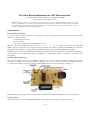
systems (more precisely on a microcontroller PIC) within the scope of an 3rd year option in telecommunications. In order
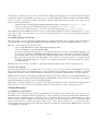
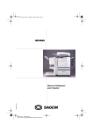
to prepare these seminars, the group worked on a 16F877 PIC integrated in an electronic card (see Figure 1).
Figure 1: Electronic board layout
The embedded operating system chosen is Salvo which is dedicated to the Microchips PIC family of microcontrollers.
1.3 Project Goals
The desired outcome is to program the PIC using Salvo functionalities and a package of lowlevel functions. 1 of 8
A schedule of conditions was imposed; the software had to enable regular updating of the current analogical and digital
temperatures displayed on the LCD, provided by two sensors, while a LED had to blink as a heartbeat. The LED blinking
shows the system is operational. A change in the kind of displayed temperatures will occur when a user exerts pressure
briefly on the interruption button:
•
•
•
At the first push, both analogical and digital minimal temperatures are displayed (print_mode == MINI)
At the second push, the two maximal temperatures are displayed (print_mode == MAXI)
One more press enables the LCD to come back to the current temperatures (print_mode = CURRENT).
If the LCD stays in a mode different from the CURRENT one then a timer enables the system to switch back to the CURRENT
mode after a couple of seconds. When a user presses the interruption button for a long time, the minimal and maximal
values will be reset.
1.4 Available Hardware and Software
The development tools were installed on a PC which was equipped with Windows™ 98. They include an Integrated
Development Environment (IDE) named MPLAB and a PIC programmer named “Universal PIC Programmer v 6.4.0”.
Moreover, some documents were provided, such as:
•
•
•
•
“User’s Guide PIC Ansi C Compiler”, Ed. HigTech Software, 2004
“Salvo User Manual v 3.1.0”, Ed. Pumpkin, 2004.
Documents detailing the development of “An Acquisitioncard based on a microcontroller Microchip PIC” from
the electronics department of ENSEIRB, 20022003. It describes the lowlevel functions included in the library
given with the subject of the project. Each state of PIC pins linked with a component of the circuit is explained.
More precisely, the datasheet of the PIC 16F87x series enabled us to know the functions of each pin and the
description of the internal registers; for instance, one of the three internal timers has been configured to generate
periodical interrupts.
The Demo Lite version of Salvo and a library of the lowlevel functions fitted to the board were provided as well.
1.5 Project Development
The project was divided into two parts. First, there was a sequence of tests developed from the lowlevel functions. Second,
the project itself was carried out: It includes the use of Salvo structure and the compilation of Salvo. In addition, a technical
manual of the used Salvo functions has been written to allow the 3rd year students to understand the code and to update it.
Tests. In a first step, the test of the LED was implemented. Then, the interruption button test used the LED's blinking to see
if the program was still running. Then the LCD, LM35, and DS1620 tests alternated the test of each function, meanwhile,
the LED was blinking to check the activity of the Microchip PIC.
Salvo. First of all, functionalities were grouped in three tasks with different priorities. Thereafter, the implementation
began with the use of the previous lowlevel functions library, the basic functions of Salvo, and the previous tests.
2 Project Description
2.1 Acquisition Card Description
The purpose of the electronic card is to develop a digital thermometer. Therefore, two thermal sensors are soldered onto it.
The LM35 sensor is analogical, it delivers a signal whose voltage is linearly proportional to the temperature. The PIC has a
builtin Analog to Digital Converter to which the sensor is connected. The second sensor, the DS1620, has a digital
interface. It can be directly initialized and controlled from the microcontroller. The human interface is quite light: a LCD
display (2x16 characters), a LED, and a button. There is also a reset button, useful in case of a system crash. The
microcontroller can be programmed from a PC using a RS232 serial interface, obtained with a MAX232 driver connected
to the Parallel Port of the PC.
2 of 8
2.2 PIC Microcontroller Overview
The core of the electronic card is the Microchip 16F877 PIC microcontroller. It is used with a clock rate of 4 MHz. It is
shipped with 8K of Flash ROM (for program storage), 368 bytes of RAM (for static variables, stack, internal registers,
etc.), and 256 bytes of EEPROM (not relevant in our project). One input pin is used as an external interrupt, linked to the
button. Another pin is an output for the LED. Other pins are used for the LCD, the sensors and the PC serial interface.
2.3 Salvo
Salvo is a cooperative realtime operating system (RTOS) that is designed for singlechip microcontrollers with severely
limited RAM and ROM. The maximum stack level is typically 4, so it can be used with low cost microcontrollers such as
Microchip PIC (family 12000, 14000, 16000, 17000 or 18000).
In fact we used Salvo Lite, a freeware version of Salvo. Some of Salvo Lite's main features are:
Cooperative, eventdriven, prioritybased multitasking RTOS Designed for processors with severely limited RAM (e.g. less than 256 bytes) Works within a hardware call; return stack of 8 levels or fewer (4 is typical) Number of tasks and events limited to three
Events allowed include semaphores, messages and message queues •
•
•
•
•
3 Programming Strategy
3.1 Tests
Test of the LED. The test of the LED involves making it blink. First, the LED port is initialized, then, in an infinite loop,
the LED pin is alternately activated and deactivated (RB5 = 1 or 0). A macro WAIT is implemented to allow users to see
the shift between states.
Test of the Button. This test involves shifting the state of the LED by pressing the button. Pressure on the button triggers
an interruption (INTF == 1) which is processed by the interrupt handler written in the function: void interrupt
IntVector(void). Then, the pressure produces a shift only if the interruption is still valid after several milliseconds.
Indeed, the interrupt handler has to avoid generating a quick host of shifts of the LED state on account of the bounce
phenomenon.
Test of the LCD. This test consists in displaying characters on the LCD screen. Four functions from LCD library are used,
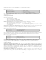
listed in Table 1.
Table 1: LCD Functions
lcd_init();
lcd_clear();
lcd_pos(line, column);
lcd_puts(“message”);
to initialize LCD
to clear the display
to position the current cursor (line from 0 to 1 and column from 0 to 15)
to display the message at the current cursor location
Test of the LM35 Analogical Sensor. This test consists in displaying the temperature read from the analogical sensor
called LM35. Two functions from the LM35 library are used. They are listed in Table 2.
Table 2: Analogical Sensor Functions
void lm35_init();
u16 lm35_readtemp();
to initialize LM35
to read the current analogical temperature
The u16 value returned by the function lm35_readtemp() is displayed thanks to the function print_int() developed
in lib1.c.
Test of the DS1620 Digital Sensor. This test consists in displaying the temperature computed by the digital sensor called
3 of 8
DS1620. Three functions from the DS1620 library are used. They are listed in Table 3.
Table 3: Digital Sensor Functions
void ds1620_init();
void ds1620_start();
u16 ds1620_readtemp();
to initialize DS1620
to start a new conversion
to read the current analogical temperature
The u16 value returned by the function ds1620_readtemp() is displayed thanks to the function print_int()
developed in lib1.c.
3.2 Description of the Tasks
The system consists of 3 tasks:
•
•
•
The first task handles the display
The second task handles the LED blinking
The third task handles the temperatures acquisition
Display Task (Function: Print()). Depending on the current mode, this task displays on the LCD:
•
•
The current analogical and digital temperatures (print_mode == CURRENT)
The minimal temperatures (print_mode == MINI) or the maximal temperatures (print_mode == MAXI)
recorded until now.
Temperatures Acquisition Task (Function: Acquisition()). The goal of this task is to retrieve analogical and digital
temperatures computed by the sensors. Then, the results are stored in the two variables listed in Table 4.
Table 4: Variables for Current Temperatures
u16 currentAna
u16 currentNum
the analogical temperature
the digital temperature
The new minimal and maximal temperatures can be inferred from comparing the previous minimal and maximal
temperatures with the current temperatures. These minimal and maximal temperatures are stored in four variables:
Table 5: Variables for Extrema Temperatures
u16
u16
u16
u16
miniNum
maxiNum
miniAna
maxiAna
Digital temperatures
Analogical temperatures
LED Blinking Task (Function: Born_to_be_alive()). This task deals with the shift of the LED state. Every call of this
task triggers a shift in the LED state. If the LED is on, the task will switch it off; if not, the task will switch it on.
3.3 Choice of Priority
Temperature Acquisition Task and Display Task. The logic is to begin with the acquisition and then to display the
temperatures which were computed. So, it would be tempting to make the acquisition a higher priority than the display
task. However, the display task cannot be considered a background task, since it would lead to too swift a refresh rate,
making the LCD difficult to read. Besides, the display task waits for a semaphore before displaying a new set of
temperatures; and it is useless to make the lowest priority task wait. So, all this leads us to set the temperature acquiring
task as a lower priority than the LCD task.
LED Blinking Task and Display Task. The LED blinking is useful to inform the user about the actual working of the
program. Indeed, if the program crashes, the LED will stop blinking. At first glance, this task seems to be the least
4 of 8
important. However, this task is also used to establish the rhythm of the display. Indeed, before displaying a new set of
temperatures, the display task will wait for a semaphore (function: OS_WaitSem()). This semaphore is released by the
LED blinking task after a delay of 500 milliseconds (functions: OS_Delay(), OSSignalSem()). So every shift of the
LED state leads to new values of temperatures on the LCD screen. As the display has to wait for a call to the LED blinking
task, it is obvious that the display task is the most important task.
LED Blinking Task and Temperature Acquisition Task. The LED blinking task is shorter than the temperature
acquisition one. Moreover, if the priority of the LED blinking task was lower than the temperature acquisition one, the
priority of the LED blinking task would be the lowest of the three, and so the LED priority blinking task would not ever be
scheduled. Indeed, the display task will wait for the semaphore and then the acquisition task will take the CPU and will not
release it. Even if this task calls a OS_Yield()1, the scheduler will give the CPU to the highest priority task among those
eligible: the acquisition task. So the LED blinking task would never have the CPU and could not wake up the display task.
It follows that the priority of the LED blinking task has to be higher than the acquisition task.
Conclusion. Priority levels were chosen from 1 to 3, 1 given the highest priority:
1 display task
2 LED blinking
3 temperature acquisition
3.4 Task progression
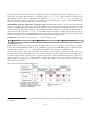
Being the highest priority, the display task takes the CPU and then waits for the semaphore (the semaphore is initially
locked). The scheduler attributes the CPU to the second highest priority task: the LED blinking task. So, the LED switches
on and the task executes an OS_Delay() which makes it unavailable for the scheduler for 500 milliseconds.
The two highest priority tasks being unavailable, the scheduler lets the acquisition task take the CPU. After every
acquisition, this task calls the scheduler. Thus, once the LED task finishes its delay of 500 milliseconds, the LED task can
be elected by the scheduler (led task priority > acquisition task priority). Then, the LED task releases the semaphore by
using the function OSSignalSem() which calls the scheduler. The scheduler chooses the display task which is now
eligible (thanks to the LED task). The temperatures are displayed according to the current mode, then, the display task
waits again for the semaphore.
The schedule of the tasks is illustrated in Figure 2.
Figure 2: Schedule of the Three Salvo Tasks
1 OS_Yield(): This function allows the current task to call the scheduler in order to release the CPU to the highest priority task among
those eligible.
5 of 8
4 Development and Experimentation: Details
4.1 Software Explanation
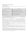
The application is written in the file main.c, divided into eight functions as shown on Table 6. Some useful shareable
functions have been written in the file lib1.c.
Table 6: Functions that can be found in file main.c
Function name and prototype
Description
int main(void)
The main function, launched on poweron and reset
void Print(void)
The task which displays the temperatures on the LCD
void Acquisition(void)
The task which acquire the data from the sensors
void Born_to_be_alive(void)
The task which informs the user that the system is running
void interrupt IntVector(void)
The interrupt handler, used both for external and timer interrupt
void pic_init(void)
Initialization of the PIC internal registers
void accueil(void)
Friendly message displayed at poweron time.
void init_value(void)
Initialization of the global variables.
Main() Interruption Enabling. The interruption are allowed by calling OSEi() (mainly for timer interrupt) and by
positioning INTE to 1 (external interrupt enabled). The call to init_value() has to be made after allowing these
interruptions, otherwise a pending external interrupt would change the value of print_mode, and the system would start
displaying the minimal temperature instead of the current values.
Acquisition(). A call to ds1620_start() triggers off a new conversion. The value stored in the DS1620 sensor is
retrieved via ds1620_readtemp(), the LM35 via lm35_readtemp(). These values are compared with the minimal and
maximal ones, which are updated if necessary. Next the task calls OS_Yield() to allow pending tasks to be executed.
Born_to_be_alive() Principle. Every time this task is scheduled, it toggles the LED state. It is delayed for 500 msec
thanks to OS_Delay(5,...). As the Salvo tick period is 100 msec (see the Interrupt Handler function), waiting for 5 Salvo
ticks corresponds to 500 msec. The task is also used for handling the timeout used for switching back to the display of
current temperatures, as explained below. It is important to delay this task before signaling the semaphore, for the first data
to be acquired before it is displayed.
Born_to_be_alive() Display Timeout. If the global variable print_mode is different from CURRENT, the variable
timeout_print_mode is decreased incrementally and once it has reached 0, the value of print_mode is set to CURRENT.
Otherwise, the timeout is reloaded.
Interrupt Handler – Timer Software Prescaler. The timer hardware prescaler is configured through the PS0, PS1 and
PS2 bits of the timer0 register to trigger off timer interrupts every 512 microseconds. Yet, it is said in the Salvo
documentation that OSTimer(), that increments Salvo ticks, has to be called at a period less than 5 msec. That's why we
had to generate a software prescaler, which divides the hardware rate by 195. The out rate of this scaler is a call to
OSTimer() every 100 msec.
Interrupt Handler – Reinitialization of Minimal and Maximal Temperatures. This is performed using a timeout, like
for the display mode. Every time a timer interrupt occurs, the program reads the state of the input pin to which the button is
connected (this state is inverted: reading 0 means the button is pressed, and viceversa). If it is pushed, the counter
timeout_longbp is decreased. Once it has reached 0, all extrema values are reset, and the display mode is set to
RAZ_EXTREMA. If the button is not pressed, the counter is reloaded.
6 of 8
Interrupt Handler – External Interrupt. Pressing the button triggers off an external interrupt. It changes the value of the
external interrupt flag INTF to 1. As any interrupt leads to calling the interrupt handler function, checking the flags is the
only way to know which interrupt has occurred, but it is not sufficient for the external interrupt: a mechanical bounces
phenomenon generates a huge number of rising edges that produces an interrupt. It is possible to avoid it thanks to an
active loop into the interrupt handler: if an external interrupt has been detected, the loop runs until the transitional
phenomenon ends. The flag INTF has to be manually reset to 0. Next, the program can perform actions needed to handle
the interrupt : incrementing the variable print_mode, that is to say changing the temperatures on the display. However an
external interrupt can occur when a reset of the extrema values is requested by the user. In this case the display mode is not
changed to ensure that the informational message will be displayed.
Initialization of the Global Variables. The initialization of the minimal temperatures cannot be accomplished by setting
them to 0, since 0 is the minimal value the system can compute, and therefore the minimal temperatures would not be
updated. The solution we have chosen is to set them to 1. As the storage variables are unsigned, 1 stands for the
maximum value (all bits equal to 1). These false minimal temperatures will not be displayed, as the values that will be
printed next will be current temperatures: both at startup or at reset requested by the user, the print_mode variable is set
to CURRENT.
4.2 Difficulties and Trouble
Variable Typing. Manipulating types such as short, signed char or unsigned long is meaningless. We have
preferred to rename them with more comprehensible labels: one letter followed by two digits. The letter can be u or s,
meaning unsigned or signed. The two digits indicate the memory space required for the storage: 08, 16 or 32 bits.
Table 7 lists all the types we have defined.
Table 7: Variable Typing
signed
Friendly type
Compiler type
unsigned
Range
Friendly type
Compiler type
Range
s08
signed char
128 .. 127
16 bits S16
signed short
32768 .. 32767 u16
unsigned short 0 .. 65535
32 bits s32
signed long
216 .. (2161)
unsigned long
8 bits
u08
u32
unsigned char
0 .. 255
0 .. (2321)
Using understandable names for types is all the more important as we worked on an embedded software program. The
memory size is very limited, so we had to be careful to use the minimal variable size according to its usage. A good
example of such an optimization is the declaration of the variable used to avoid the bounce phenomenon, in the interrupt
handler IntVector(). The maximum value of this variable can be fixed through the macroconstant ANTI_BOUNCE. A
simple test computed by the C preprocessor compares ANTI_BOUNCE with 255 and eventually with 65535. If the first test
(Is ANTI_BOUNCE inferior or equal to 255?) is positive, the type of the variable is u08. Otherwise, the second test is
conducted. If it is positive, the type is u16, else it is u32.
MPLAB Configuration. The Integrated Development Environment we used, called MPLAB, was some trouble to
configure. A strict and nonintuitive order has to be followed in order to allow more than one file to be included in the
software project. The same kind of trouble made us spend a couple of hours selecting and adding right options for the
integrated compiler. Moreover, the text editor into which we typed the software code was very capricious, since most of
the time it refused to handle the keystroke necessary for writing '#', '{', or'}'. Contrary to smart editors like Emacs or Vim,
MPLAB doesn't allow features such as syntax highlighting and coloration, automatic indentation and autocompletion.
Salvo Configuration. Since Salvo was designed to run on many families of PIC microcontrollers, and even now on
Motorola's or other hardware architectures, the configuration files are somewhat complicated. The specifications of each
microcontroller, such as the number of ports, the functions assigned to each pin, and even the name of the internal
7 of 8
registers, have to be handled by them. A “#define SYSA” declaration needed to be added to the compiler command line
in order to specify the family of PIC we used. The configuration howto is written in the Salvo manual, but since the
manual is a bit confusing and disorganized, we did not see this part on our first reading. Salvo is really not easy to
configure unless the user reads its manual carefully.
Long Pressure on the Button. Catching an interrupt is not sufficient to know how long the button has been pressed.
Therefore, we had to consider the button as an input and not as an interrupt trigger.
Timer Interrupt Frequency. The notion of time in a realtime operating system is critical. In our system, it is managed
thanks to periodic interruptions generated by an internal timer (timer0). This timer can be configured through a register,
mainly the hardware prescaler value. Indeed, the principle of the timer interrupts is as follows: the external clock of the
PIC is first divided by 4 (constant factor) to get a 1 MHz input clock. Then, this periodic signal goes into a software
configurable prescaler. The output frequency determines the timer interrupt frequency. The problem we have encountered
is an inexplicable slowdown of the frequency. We have set the prescaler to its maximum value, 1024. Thus, the output
frequency should have been about 1 KHz, and cannot be set to be slower. However, we notice that it sometimes reached as
low as 15 Hz. This variation even occurred while the software was running, even if it changed most of the time when we
recompiled the code and reprogrammed the microcontroller. We did not understand how this could happen, but we have
fixed it by correctly setting the timer register in the Salvo configuration instead of in our own configuration function,
pic_init().
5 Conclusion
5.1 Comments About the Project
Developing an embedded software program is really exciting, as some aspects we don't pay attention to in computer
software development have to be considered: memory usage, hardware storage of variables, bit manipulation, registers
configuration, and many other lowlevel concepts. The development method is also interesting: starting with easytouse
interfaces, such as a LED or an interrupter, the system progressively emerges from nothing, to finally carry out the desired
tasks.
However, problems resulting from the use of the IDE and the programmer as well as Salvo were disarming. The IDE
required a huge amount of time to configure. Moreover, the editor in MPLAB was not as smart as Emacs. The programmer
was very slow under Windows™ NT, as a result, the group asked for a new computer with Windows™ 98. To fit the
numerous kinds of PIC, the programming tools were adaptable. However, the configuration was not immediate and not
obvious. As a consequence, we spent a lot of time on mastering our development environment.
5.2 Salvo Use in Everyday Life
RTOS are commonly used in applications with critical time and reliability requirements, such as military and aerospace
applications, but they are also used by telecommunications equipment manufacturers in data modems, communication
servers, or ATM switches, for example
References
[1] “User’s Guide PIC Ansi C Compiler”, Ed. HigTech Software, 2004
[2] “Salvo User Manual v 3.1.0”, Ed. Pumpkin, 2004.
[3] Subject of the development of “An Acquisitioncard based on a microcontroller Micropchip PIC” from the electronic department of
ENSEIRB, 20022003.
[4] Datasheet of the PIC 16F87x series
8 of 8