1
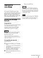
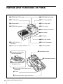
4-260-664-11 (1)
HD Camera Adaptor
Operating Instructions
Before operating the unit, please read this manual thoroughly
and retain it for future reference.
XDCA-55
© 2010 Sony Corporation
4260664110
WARNING
To reduce the risk of fire or
electric shock, do not expose
this apparatus to rain or
moisture.
To avoid electrical shock, do
not open the cabinet. Refer
servicing to qualified
personnel only.
This symbol is intended to
alert the user to the presence
of important operating and
maintenance (servicing)
instructions in the literature
accompanying the appliance.
Important Safety Instructions
•
•
•
•
•
•
•
Read these instructions.
Keep these instructions.
Heed all warnings.
Follow all instructions.
Do not use this apparatus near water.
Clean only with dry cloth.
Do not block any ventilation openings.
Install in accordance with the
manufacturer's instructions.
• Do not install near any heat sources such
as radiators, heat registers, stoves, or
other apparatus (including amplifiers)
that produce heat.
• Do not defeat the safety purpose of the
polarized or grounding-type plug. A
polarized plug has two blades with one
wider than the other. A grounding-type
plug has two blades and a third grounding
prong. The wide blade or the third prong
are provided for your safety. If the
provided plug does not fit into your
outlet, consult an electrician for
replacement of the obsolete outlet.
• Protect the power cord from being
walked on or pinched particularly at
plugs, convenience receptacles, and the
point where they exit from the apparatus.
2
• Only use attachments/accessories
specified by the manufacturer.
• Use only with the cart, stand, tripod,
bracket, or table specified by the
manufacturer, or sold with the apparatus.
When a cart is used, use caution when
moving the cart/apparatus combination
to avoid injury from tip-over.
• Unplug this apparatus during lightning
storms or when unused for long periods
of time.
• Refer all servicing to qualified service
personnel. Servicing is required when the
apparatus has been damaged in any way,
such as power-supply cord or plug is
damaged, liquid has been spilled or
objects have fallen into the apparatus, the
apparatus has been exposed to rain or
moisture, does not operate normally, or
has been dropped.
IMPORTANT
The nameplate is located on the bottom.
WARNING
Excessive sound pressure from a headset
can cause hearing loss.
In order to use this product safely, avoid
prolonged listening at excessive sound
pressure levels.
The total power consumption including this
adaptor’s power consumption, DC power
output, and power supply to the camcorder
must not exceed 70 W.
For the customers in the U.S.A.
This equipment has been tested and found
to comply with the limits for a Class A
digital device, pursuant to Part 15 of the
FCC Rules. These limits are designed to
provide reasonable protection against
harmful interference when the equipment is
operated in a commercial environment.
This equipment generates, uses, and can
radiate radio frequency energy and, if not
installed and used in accordance with the
instruction manual, may cause harmful
interference to radio communications.
Operation of this equipment in a residential
area is likely to cause harmful interference
in which case the user will be required to
correct the interference at his own expense.
You are cautioned that any changes or
modifications not expressly approved in
this manual could void your authority to
operate this equipment.
All interface cables used to connect
peripherals must be shielded in order to
comply with the limits for a digital device
pursuant to Subpart B of Part 15 of FCC
Rules.
This device complies with Part 15 of the
FCC Rules. Operation is subject to the
following two conditions: (1) this device
may not cause harmful interference, and (2)
this device must accept any interference
received, including interference that may
cause undesired operation.
For the customers in Canada
This Class A digital apparatus complies
with Canadian ICES-003.
For the customers in Europe
This product with the CE marking complies
with the EMC Directive issued by the
Commission of the European Community.
Compliance with this directive implies
conformity to the following European
standards:
• EN55103-1: Electromagnetic
Interference (Emission)
• EN55103-2: Electromagnetic
Susceptibility (Immunity)
This product is intended for use in the
following Electromagnetic Environments:
E1 (residential), E2 (commercial and light
industrial), E3 (urban outdoors), E4
(controlled EMC environment, ex. TV
studio).
The manufacturer of this product is Sony
Corporation, 1-7-1 Konan, Minato-ku,
Tokyo, Japan.
The Authorized Representative for EMC
and product safety is Sony Deutschland
GmbH, Hedelfinger Strasse 61, 70327
Stuttgart, Germany. For any service or
guarantee matters please refer to the
addresses given in separate service or
guarantee documents.
AVERTISSEMENT
Afin de réduire les risques
d’incendie ou d’électrocution,
ne pas exposer cet appareil à
la pluie ou à l’humidité.
Afin d’écarter tout risque
d’électrocution, garder le
coffret fermé. Ne confier
l’entretien de l’appareil qu’à
un personnel qualifié.
IMPORTANT
La plaque signalétique se situe sous
l’appareil.
AVERTISSEMENT
Une pression acoustique excessive en
provenance du casque peut provoquer une
baisse de l’acuité auditive.
Pour utiliser ce produit en toute sécurité,
évitez l’écoute prolongée à des pressions
sonores excessives.
Pour les clients au Canada
Cet appareil numérique de la classe A est
conforme à la norme NMB-003 du Canada.
Pour les clients en Europe
Ce produit portant la marque CE est
conforme à la Directive sur la compatibilité
électromagnétique (EMC) émise par la
Commission de la Communauté
européenne.
3
La conformité à cette directive implique la
conformité aux normes européennes
suivantes :
• EN55103-1 : Interférences
électromagnétiques (émission)
• EN55103-2 : Sensibilité
électromagnétique (immunité)
Ce produit est prévu pour être utilisé dans
les environnements électromagnétiques
suivants : E1 (résidentiel), E2 (commercial
et industrie légère), E3 (urbain extérieur) et
E4 (environnement EMC contrôlé, ex.
studio de télévision).
Le fabricant de ce produit est Sony
Corporation, 1-7-1 Konan, Minato-ku,
Tokyo, Japon.
Le représentant autorisé pour EMC et la
sécurité des produits est Sony Deutschland
GmbH, Hedelfinger Strasse 61, 70327
Stuttgart, Allemagne. Pour toute question
concernant le service ou la garantie,
veuillez consulter les adresses indiquées
dans les documents de service ou de
garantie séparés.
WARNUNG
Um die Gefahr von Bränden
oder elektrischen Schlägen zu
verringern, darf dieses Gerät
nicht Regen oder Feuchtigkeit
ausgesetzt werden.
Um einen elektrischen Schlag
zu vermeiden, darf das
Gehäuse nicht geöffnet
werden. Überlassen Sie
Wartungsarbeiten stets nur
qualifiziertem Fachpersonal.
WICHTIG
Das Namensschild befindet sich auf der
Unterseite des Gerätes.
4
WARNUNG
Zu hoher Schalldruck von Headset kann
Gehörschäden verursachen.
Um dieses Produkt sicher zu verwenden,
vermeiden Sie längeres Hören bei sehr
hohen Schalldruckpegeln.
Für Kunden in Europa
Dieses Produkt besitzt die CEKennzeichnung und erfüllt die EMVRichtlinie der EG-Kommission.
Angewandte Normen:
• EN55103-1: Elektromagnetische
Verträglichkeit (Störaussendung)
• EN55103-2: Elektromagnetische
Verträglichkeit (Störfestigkeit)
Für die folgenden elektromagnetischen
Umgebungen: E1 (Wohnbereich), E2
(kommerzieller und in beschränktem Maße
industrieller Bereich), E3 (Stadtbereich im
Freien) und E4 (kontrollierter EMVBereich, z.B. Fernsehstudio).
Der Hersteller dieses Produkts ist Sony
Corporation, 1-7-1 Konan, Minato-ku,
Tokyo, Japan.
Der autorisierte Repräsentant für EMV und
Produktsicherheit ist Sony Deutschland
GmbH, Hedelfinger Strasse 61, 70327
Stuttgart, Deutschland. Bei jeglichen
Angelegenheiten in Bezug auf
Kundendienst oder Garantie wenden Sie
sich bitte an die in den separaten
Kundendienst- oder Garantiedokumenten
aufgeführten Anschriften.
Table of Contents
Overview ..................................................................................6
Features ...................................................................................6
Using the CD-ROM ................................................................7
Reading the CD-ROM Manuals ..........................................7
Names and Functions of Parts ............................................... 8
System Configuration........................................................... 12
Attaching the Adaptor to a Camcorder .............................12
Important Notes on Operation ............................................14
Specifications .........................................................................14
General ..............................................................................14
Connectors ........................................................................15
Supplied Accessories ........................................................15
Accessories Not Supplied .................................................15
Table of Contents
5
Overview
Features
The XDCA-55 HD Camera Adaptor
(referred to as “the adaptor” hereafter)
allows you to connect an XDCU-50 HD
Camera Extension Unit to supply power to
the camcorder and extend the distance over
which camcorder input and output signals
can be transmitted (maximum distance
100 m (328 feet)).
HD digital transmission
Can be installed on the following
camcorders
• PMW-350K/350L 1)
• PMW-320K/320L 1)
• PMW-500 2)
1) An optional CBK-CE01 50 Pin Interface and
Digital Extender is required.
2) An optional CBK-HD02 SDI/COMPOSITE
Input and 50 Pin Interface is required.
For details, refer to the XDCU-50 Operating
Instructions for information about how to set up a
system consisting of this adaptor, a camcorder, and
the XDCU-50, and for precautions about use of the
system.
This adaptor supports bidirectional
transmission of uncompressed HD digital
signals between this adaptor and
XDCU-50.
The maximum transmission distance is
100 m (328 feet).
You can transmit high-quality video signals
regardless of cable length.
Cable-free connection via 50-pin
interface
You can easily make a cable-free
connection by connecting the camcorder
connector of this adaptor directly to the
camera adaptor connector of the camcorder
(requires installation of optional interface).
Monitor output connector
Either main line video signals from the
camcorder or return video signals from the
XDCU-50 can be output as HDSDI signals.
Return video selection button
You can switch the monitor output to return
video while the adaptor’s RET button is
held down.
Communication interfaces
• Intercom (1 line)
• Tally (red and green)
• Trunk line (1 line)
6
Overview / Features
This opens the PDF file.
Using the
CD-ROM
The supplied CD-ROM contains PDFformat Operating Instructions manuals (in
English, Japanese, French, German, Italian,
Spanish, and Chinese) for this adaptor, a
HD Camera Adaptor XDCA-53 and a HD
Camera Extension Unit XDCU-50.
Memo
The files may not be displayed properly,
depending on the version of Adobe Reader.
In such a case, install the latest version you
can download from the URL mentioned in
“Preparations” above.
Note
If you have lost or damaged the CD-ROM,
you can purchase a new one to replace it.
Contact a Sony service representative.
Reading the CD-ROM
Manuals
Preparations
The following program must be installed on
your computer in order to read the
documents contained on the CD-ROM.
Adobe Reader Version 6.0 or higher
Memo
If Adobe Reader is not installed, you can
download it from the following URL:
http://www.adobe.com/
Adobe and Adobe Reader are trademarks of
Adobe Systems Incorporated in the United States
and/or other countries.
To read the documents
Do the following:
1
Insert the CD-ROM in your CD-ROM
drive.
A cover page appears automatically in
your browser.
If it does not appear automatically in
the browser, double-click on the
index.htm file on the CD-ROM.
2
Select and click on the manual that you
wish to read.
Using the CD-ROM
7
Names and Functions of Parts
qhINTERCOM LEVEL knob
1INTERCOM MIC switch
qgCEU connector
2TALLY lamp (green)
qfAUX connector
3TALLY lamp (red)
qdINTERCOM connector
4TALLY switch
5Belt bracket screw holes
6CALL button
7RET button
8MONI. SEL switch
qsDC OUT 12V 1A
connector
9CEU OUT connector
qaMONITOR OUT(SDI) connector
0CEU IN connector
wdAccessory screw holes
(for HD viewfinder)
qjCamcorder screws
qkCamcorder connector
wsAccessory screw holes
(for general use)
waCamcorder bracket attachment
screw hole
w;V shoe
qlCamcorder power supply connector
8
Names and Functions of Parts
a INTERCOM MIC switch
Controls the headset microphone connected
to the INTERCOM connector, turning it on
or off as required.
ON: Turns the headset microphone on.
OFF: Turns the headset microphone off.
PTT: Turns the headset microphone on for
as long as the switch is held in this
position.
b TALLY lamp (green)
When the TALLY switch is on, lights in
green when a green tally signal is input to
an XDCU-50 connected to the adaptor.
c TALLY lamp (red)
When the TALLY switch is on, lights in red
when a red tally signal is input to an
XDCU-50 connected to the adaptor, and
when a call signal is received, for example
because a CALL button was pressed on
another device.
Note
This lamp does not light when the adaptor’s
CALL button is pressed.
d TALLY switch
Enables (on) or disables (off) the TALLY
lamps (red and green).
However, tally signals assigned to pins 14
and 15 of the AUX connector are not
affected by the setting of this switch.
ON: Lights the TALLY lamps (red and
green) according to tally signals and
the state of the CALL button.
OFF: Does not light the TALLY lamps (red
and green).
e Belt bracket screw holes
These are screw holes (2) for M3 screws to
secure a belt bracket.
f CALL button
Calls the operator of a XDCU-50 or remote
control unit.
When this button is pressed, the TALLY or
CALL lamps on the camcorder, the XDCU50, and the remote control unit light. On the
other hand, the TALLY lamp on this
adaptor does not light.
Note
Control over tally lamps varies depending
on the devices used in the system
(camcorder, XDCU-50, remote control
unit).
For details, refer to the instruction manuals of the
other devices.
g RET (return) button
Switches the video in the viewfinder to
return video.
When the MONI. SEL switch is set to
CAM/RET, you can also switch the output
signal from the MONITOR OUT(SDI)
connector to return video.
h MONI. SEL (monitor select) switch
Selects the output from the MONITOR
OUT(SDI) connector.
RET: Always outputs return video signals.
CAM/RET: Outputs return video as long
as the RET button is pressed, and
outputs camcorder video signal when
the RET button is not pressed.
i CEU OUT (camera extension unit
output) connector
Connect to the CA IN connector of the
XDCU-50 with a BNC cable (5C-FB).
j CEU IN (camera extension unit
input) connector
Connect to the CA OUT connector of the
XDCU-50 with a BNC cable (5C-FB).
k MONITOR OUT(SDI) connector
Outputs HD SDI signals, either return video
signals from the XDCU-50 video signals
from the camcorder.
Names and Functions of Parts
9
l DC OUT 12V 1A connector (XLR 4pin)
Supplies +12 V power to a monitor or other
external device.
The pin assignments are as follows.
Pin No.
Signal name
GND
Pin Signal name
No.
Description
1
2
Not used
2
TC (X) OUT
3
Not used
7
TC (G) OUT
Timecode signal
output
4
+12V
3
TRUNK RX
13
TRUNK TX
8
TRUNK (G)
4
RET CONT IN
Return control
external input
On: GND
Off: Open
9
MIC CONT IN
Intercom
microphone
control input
On: GND
Off: Open
m INTERCOM connector (XLR 5-pin)
Allows you to connect an XLR 5-pin type
headset. The pin assignments are as
follows.
Trunk line (RS232C)
Pin No.
Signal name
5
GND
Ground
1
INCOM MIC GND
10
TALLY GND
TALLY output
2
INCOM MIC IN
14
R TALLY OUT
Red tally output
(open collector)
3
INCOM RECEIVE GND
15
G TALLY OUT
4
INCOM RECEIVE OUT
5
Not used
Green tally
output (open
collector)
1
AUX VIDEO (X) Generalpurpose analog
AUX VIDEO (G)
video line
between this
adaptor and
XDCU-50
Contact your dealer or a Sony service representative
for information about how to adjust the side tone
level.
n AUX connector (15-pin)
Connect to an external system to input and
output tally signals, trunk line signals, and
timecode.
10
Provides a trunk line connection to the
trunk line of the camera adaptor via a RS232C interface, for use as a
communications line with external devices.
Also equipped with general-purpose lines
between this camcorder and the XDCU-50.
The pin assignments are as follows.
Names and Functions of Parts
6
Pin Signal name
No.
Description
11
Generalpurpose line 1
between this
adaptor and
XDCU-50
12
AUX1
AUX2
Generalpurpose line 2
between this
adaptor and
XDCU-50
o CEU (camera extension unit)
connector (26-pin)
Connect to the CA connector (26-pin) of the
XDCU-50 with the optional CCZ-A cable.
Power is supplied from the XDCU-50.
u Camcorder bracket attachment
screw hole
This is a screw hole for a bracket to increase
the security of the attachment of this
adaptor to the camcorder.
v Accessory screw holes (for general
use)
These are a screw hole for an U1/4-20
screw to secure an accessory, and eight
screw holes to secure the accessory fitting
shoe (for the DXF-C50W viewfinder).
w Accessory screw holes (for HD
viewfinder)
These are accessory screw holes (4) for M4
screws to secure an HD monitor.
For details on the pin assignments, refer to the
description on the CA OUT connector in the
Operating Instructions for the XDCU-50.
p INTERCOM LEVEL knob
Adjusts the receiving volume level of the
headset connected to the INTERCOM
connector.
q Camcorder screws
Screws to secure the adaptor to the
camcorder.
r Camcorder connector (50-pin)
Connect to the camera adaptor connector of
the camcorder (requires installation of an
optional interface) to send and receive
video and audio signals.
s Camcorder power supply connector
Supplies power to the camcorder.
t V shoe
This is a V shoe for attachment of this
adaptor to the camcorder.
Names and Functions of Parts
11
System Configuration
The following figure shows the
configuration of a system that includes the
adaptor.
Refer to the XDCU-50 Operating Instructions for
details about how to use the adaptor when it is
connected to the XDCU-50.
Camcorder (with optional CBKCE01/HD02 installed in the
camera adaptor connector)
XDCU-50
This adaptor
a) CCZ-A cable
b) BNC cable
Note
Do not connect or disconnect the cables
connecting this adaptor and XDCU-50
(CCZ-A and BNC cables) while the system
is powered on. The excessive current
protection function may be activated,
cutting off power to the power circuits of
this adaptor or the XDCU-50.
If the power should be cut off, connect the
cables again in the proper fashion and wait
for a while before starting the system again.
Attaching the Adaptor to a
Camcorder
1
Screw two of the brackets supplied
with this adaptor to the battery
attachment shoe of the camcorder.
Brackets (supplied)
2
3
12
System Configuration
Attach the adaptor to the battery
attachment shoe of the camcorder.
Tighten the attachment screws at the
top of the adaptor.
Attachment screws
5
Attach the supplied brackets with
screws.
Note
Tighten the screws securely so that the unit
will not fall off.
To remove
Perform the installation procedure in
reverse, loosening the screws that were
tightened then.
4
Screw the remaining two of the
brackets supplied with this adaptor to
the brackets fixed in step 1 and the side
panel of this adaptor.
Brackets (supplied)
The release button on the camcorder will
not function.
System Configuration
13
Important Notes
on Operation
Specifications
General
Use and storage locations
Store in a level, ventilated place. Avoid
using or storing the adaptor in the following
places.
• In excessive heat or cold (operating
temperature range: –5°C to +40°C
(–23°F to +104°F))
• Remember that in summer in warm
climates the temperature inside a car with
the windows closed can easily exceed
50°C (122°F).
• In damp or dusty locations
• Locations where the adaptor may be
exposed to rain
• Locations subject to violent vibration
• Near strong magnetic fields
• Close to radio or TV transmitters
producing strong electromagnetic fields.
• In direct sunlight or close to heaters for
extended periods
Do not subject to strong shocks
Power requirements
13 V DC
Power consumption
Approx. 4 W
Notes
• Connect only a device with a power
consumption current of 1A or less to
the DC OUT connector.
• The total power consumption
including this adaptor’s power
consumption, DC power output, and
power supply to the camcorder must
not exceed 70 W.
Operating temperature
–5°C to +40°C (–23ºF to +104ºF)
Operating humidity
20% to 90%
Storage temperature
–20°C to +60°C (–4ºF to +40ºF)
Dimensions
Do not drop the adaptor or subject it to
strong shocks. The adaptor may be
damaged.
Do not wrap in a cloth or other
covering during operation
Internal temperatures may rise, causing
malfunctions.
Maintenance
Clean the cabinet and panels by wiping
lightly with a soft, dry cloth. If they are very
dirty, use a cloth dampened with a small
amount of neutral detergent, then wipe dry.
Avoid the use of volatile solvents such as
thinners, alcohol, benzene, and insecticides.
They may damage the surface finish or
cause it to peel off.
14
Important Notes on Operation / Specifications
(unit: mm (inches))
Mass
Approx. 1.0 kg (2 lb 3.3 oz)
Connectors
Camera extension input/output
connectors
CEU IN/OUT
BNC type (1 each), 0.8 Vp-p, 75Ω
CEU(26Pin)
CCZ 26-pin, female
Camcorder input/output
connectors
Camcorder connector
50-pin, female
Output connectors
MONITOR OUT(SDI)
BNC type, 0.8 Vp-p, 75Ω
Design and specifications are subject to
change without notice.
Note
Always verify that the unit is operating
properly before use. SONY WILL NOT
BE LIABLE FOR DAMAGES OF ANY
KIND INCLUDING, BUT NOT
LIMITED TO, COMPENSATION OR
REIMBURSEMENT ON ACCOUNT OF
THE LOSS OF PRESENT OR
PROSPECTIVE PROFITS DUE TO
FAILURE OF THIS UNIT, EITHER
DURING THE WARRANTY PERIOD
OR AFTER EXPIRATION OF THE
WARRANTY, OR FOR ANY OTHER
REASON WHATSOEVER.
Other connectors
INTERCOM
XLR 5-pin, female
AUX D-Sub 15-pin, female
Camcorder power supply
5-pin, female
DC OUT 12V 1A
XLR 4-pin, female
DC 12 V, maximum rated current
1A
Supplied Accessories
Operating Instructions
Japanese (1)
English (1)
CD-ROM (1)
Brackets (4)
Bracket fixing screws (10)
Belt bracket (1)
Belt bracket fixing screws (2)
Cable clamp belt (1)
Accessories Not Supplied
Accessory shoe kit (A-8274-966-B)
Specifications
15
Printed in China