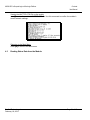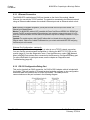
1
MVI69-GEC CompactLogix or MicroLogix Platform Generic ASCII Ethernet Communication Module February 18, 2014 USER MANUAL Your Feedback Please We always want you to feel that you made the right decision to use our products. If you have suggestions, comments, compliments or complaints about our products, documentation, or support, please write or call us. ProSoft Technology 5201 Truxtun Ave., 3rd Floor Bakersfield, CA 93309 +1 (661) 716-5100 +1 (661) 716-5101 (Fax) www.prosoft-technology.com [email protected] © 2014 ProSoft Technology, Inc. All rights reserved. MVI69-GEC User Manual February 18, 2014 ® ProSoft Technology , is a registered Copyright of ProSoft Technology, Inc. All other brand or product names are or may be trademarks of, and are used to identify products and services of, their respective owners. In an effort to conserve paper, ProSoft Technology no longer includes printed manuals with our product shipments. User Manuals, Datasheets, Sample Ladder Files, and Configuration Files are provided on the enclosed DVD and are available at no charge from our web site: http://www.prosoft-technology.com Important Installation Instructions Power, Input, and Output (I/O) wiring must be in accordance with Class I, Division 2 wiring methods, Article 501-4 (b) of the National Electrical Code, NFPA 70 for installation in the U.S., or as specified in Section 18-1J2 of the Canadian Electrical Code for installations in Canada, and in accordance with the authority having jurisdiction. The following warnings must be heeded: WARNING - EXPLOSION HAZARD - SUBSTITUTION OF COMPONENTS MAY IMPAIR SUITABILITY FOR CLASS I, DIV. 2; WARNING - EXPLOSION HAZARD - WHEN IN HAZARDOUS LOCATIONS, TURN OFF POWER BEFORE REPLACING OR WIRING MODULES WARNING - EXPLOSION HAZARD - DO NOT DISCONNECT EQUIPMENT UNLESS POWER HAS BEEN SWITCHED OFF OR THE AREA IS KNOWN TO BE NON-HAZARDOUS. THIS DEVICE SHALL BE POWERED BY CLASS 2 OUTPUTS ONLY. MVI (Multi Vendor Interface) Modules WARNING - EXPLOSION HAZARD - DO NOT DISCONNECT EQUIPMENT UNLESS POWER HAS BEEN SWITCHED OFF OR THE AREA IS KNOWN TO BE NON-HAZARDOUS. AVERTISSEMENT - RISQUE D'EXPLOSION - AVANT DE DÉCONNECTER L'ÉQUIPEMENT, COUPER LE COURANT OU S'ASSURER QUE L'EMPLACEMENT EST DÉSIGNÉ NON DANGEREUX. Warnings North America Warnings A B C Warning - Explosion Hazard - Substitution of components may impair suitability for Class I, Division 2. Warning - Explosion Hazard - When in hazardous locations, turn off power before replacing or rewiring modules. Warning - Explosion Hazard - Do not disconnect equipment unless power has been switched off or the area is known to be non-hazardous. Suitable for use in Class I, Division 2 Groups A, B, C and D Hazardous Locations or Non-Hazardous Locations. ATEX Warnings and Conditions of Safe Usage Power, Input, and Output (I/O) wiring must be in accordance with the authority having jurisdiction. A Warning - Explosion Hazard - When in hazardous locations, turn off power before replacing or wiring modules. B Warning - Explosion Hazard - Do not disconnect equipment unless power has been switched off or the area is known to be non-hazardous. C These products are intended to be mounted in an IP54 enclosure. The devices shall provide external means to prevent the rated voltage being exceeded by transient disturbances of more than 40%. This device must be used only with ATEX certified backplanes. D DO NOT OPEN WHEN ENERGIZED. Warning: This module is not hot-swappable! Always remove power from the rack before inserting or removing this module, or damage may result to the module, the processor, or other connected devices. Battery Life Advisory The MVI46, MVI56, MVI56E, MVI69, and MVI71 modules use a rechargeable Lithium Vanadium Pentoxide battery to backup the real-time clock and CMOS. The battery should last for the life of the module. The module must be powered for approximately twenty hours before the battery becomes fully charged. After it is fully charged, the battery provides backup power for the CMOS setup and the real-time clock for approximately 21 days. When the battery is fully discharged, the module will revert to the default BIOS and clock settings. The battery is not user-replaceable. Markings Electrical Ratings Backplane Current Load: 800 mA @ 5.1 Vdc Power Supply Distance Rating: 2 Operating Temperature: 0°C to 60°C (32°F to 140°F) Storage Temperature: -40°C to 85°C (-40°F to 185°F) Relative Humidity: 5% to 95% (with no condensation) All phase conductor sizes must be at least 1.3 mm(squared) and all earth ground conductors must be at least 4mm(squared). Label Markings Class I, Division 2 Groups A, B, C, D II 3 G Ex nA IIC X 0°C <= Ta <= +60°C II - Equipment intended for above ground use (not for use in mines). 3 - Category 3 equipment, investigated for normal operation only. G - Equipment protected against explosive gasses. Agency Approvals and Certifications Agency Applicable Standard(s) ATEX EN 60079-0:2006, EN 60079-15:2005 DNV DET NORSKE VERITAS Test 2.4 CE EMC-EN61326-1:2006; EN61000-6-4:2007 CB Safety CA/10533/CSA, IEC 61010-1 Ed. 2, CB 243333-2056722 (2090408) GOST-R EN 61010 ME06 MVI69-GEC ♦ CompactLogix or MicroLogix Platform Contents User Manual Contents Your Feedback Please ........................................................................................................................ 2 Important Installation Instructions ....................................................................................................... 2 MVI (Multi Vendor Interface) Modules ................................................................................................ 2 Warnings ............................................................................................................................................. 3 Battery Life Advisory ........................................................................................................................... 3 Markings .............................................................................................................................................. 3 1 Start Here 1.1 1.2 1.3 1.4 1.5 1.6 1.7 1.7.1 1.8 2 7 System Requirements ............................................................................................... 7 Package Contents ..................................................................................................... 8 Installing ProSoft Configuration Builder Software ..................................................... 9 Setting Jumpers ........................................................................................................ 9 Installing the Module ............................................................................................... 10 Connecting Your PC to the Processor .................................................................... 14 Downloading the Sample Program to the Processor .............................................. 14 Configuring the RSLinx Driver for the PC COM Port .............................................. 15 Connecting Your PC to the Module ......................................................................... 17 MVI69-GEC Configuration 2.1 2.1.1 2.1.2 2.2 2.3 2.3.1 2.3.2 2.3.3 2.3.4 2.3.5 2.3.6 2.4 2.5 3 Using ProSoft Configuration Builder ....................................................................... 19 Setting Up the Project ............................................................................................. 20 Renaming PCB Objects .......................................................................................... 21 [Module] ................................................................................................................... 22 [Server x] ................................................................................................................. 22 Enabled ................................................................................................................... 22 Service Port Number ............................................................................................... 22 Connection Timeout ................................................................................................ 22 Connection Close Type ........................................................................................... 23 Swap Rx Data Bytes ............................................................................................... 23 Swap Tx Data Bytes ................................................................................................ 23 Ethernet Configuration - MVI56E ............................................................................ 23 Downloading the Configuration to the Module Using Serial .................................... 24 Ladder Logic 3.1 3.1.1 3.1.2 3.1.3 3.1.4 3.1.5 3.2 3.3 ProSoft Technology, Inc. February 18, 2014 19 27 Module Data ............................................................................................................ 27 GECInStat (Status Object) ...................................................................................... 31 GECServerStat (Server Status Object) ................................................................... 32 GECBlkStat (Block Error Status Object) ................................................................. 32 GECClientStat ......................................................................................................... 33 GECBackplane (Backplane Object) ........................................................................ 34 Adding the Module to an Existing CompactLogix Project ....................................... 35 Adding the Module to an Existing MicroLogix Project ............................................. 37 Page 5 of 86 Contents User Manual 4 MVI69-GEC ♦ CompactLogix or MicroLogix Platform Diagnostics and Troubleshooting 4.1 4.1.1 4.1.2 4.1.3 4.2 4.2.1 4.2.2 4.2.3 4.2.4 4.3 5 LED Status Indicators ............................................................................................. 41 Ethernet LED Indicators .......................................................................................... 42 Clearing a Fault Condition ...................................................................................... 42 Troubleshooting ...................................................................................................... 42 Using ProSoft Configuration Builder (PCB) for Diagnostics ................................... 43 Using the Diagnostic Window in ProSoft Configuration Builder ............................. 43 Navigation ............................................................................................................... 45 Main Menu .............................................................................................................. 46 Network Menu ......................................................................................................... 50 Reading Status Data from the Module ................................................................... 51 Sending and Receiving ASCII Data 5.1 5.2 5.2.1 5.2.2 6 6.1.1 6.1.2 6.1.3 6.2 6.2.1 6.3 6.3.1 6.3.2 6.3.3 6.4 7 53 Sending ASCII Data ................................................................................................ 53 Receiving ASCII Data ............................................................................................. 53 Receiving ASCII Text as a Client............................................................................ 54 Receiving ASCII Text as a Server .......................................................................... 54 Reference 6.1 41 55 Product Specifications ............................................................................................ 55 General Specifications ............................................................................................ 55 Hardware Specifications ......................................................................................... 55 Functional Specifications - MVI69-GEC ................................................................. 56 Functional Overview ............................................................................................... 57 General Concepts ................................................................................................... 57 Cable Connections ................................................................................................. 71 Ethernet Connection ............................................................................................... 72 RS-232 Configuration/Debug Port .......................................................................... 72 DB9 to RJ45 Adaptor (Cable 14) ............................................................................ 75 MVI69-GEC Status Data For Block Transfer .......................................................... 75 Support, Service & Warranty 83 7.1 7.2 Contacting Technical Support................................................................................. 83 Warranty Information .............................................................................................. 84 Index 85 Page 6 of 86 ProSoft Technology, Inc. February 18, 2014 MVI69-GEC ♦ CompactLogix or MicroLogix Platform Contents User Manual 1 Start Here In This Chapter System Requirements............................................................................. 7 Package Contents .................................................................................. 8 Installing ProSoft Configuration Builder Software ................................... 9 Setting Jumpers ...................................................................................... 9 Installing the Module ..............................................................................10 Connecting Your PC to the Processor ...................................................14 Downloading the Sample Program to the Processor .............................14 Connecting Your PC to the Module .......................................................17 To get the most benefit from this User Manual, you should have the following skills: Rockwell Automation® RSLogix™ software: launch the program, configure ladder logic, and transfer the ladder logic to the processor Microsoft Windows: install and launch programs, execute menu commands, navigate dialog boxes, and enter data Hardware installation and wiring: install the module, and safely connect GEC and CompactLogix or MicroLogix devices to a power source and to the MVI69-GEC module’s application port(s) 1.1 System Requirements The MVI69-GEC module requires the following minimum hardware and software components: Rockwell Automation CompactLogix processors or MicroLogix 1500 LRP processor, with compatible power supply and one free slot in the rack, for the MVI69-GEC module. The module requires 800 mA of available power. Important: The MVI69-GEC module has a power supply distance rating of 2 (L43 and L45 installations on first 2 slots of 1769 bus). Important: For 1769-L23x processors, please make note of the following limitations. 1769-L23-QBFC1B = 800 mA at 5 Vdc (One MVI69-GEC will use all 800 mA of available power. No other modules can be used with an MVI69 module connected to this processor.) 1769-L23E-QB1B = 1000 mA at 5 Vdc (One MVI69-GEC will use 800 mA of available power. One other module can be used on this rack provided it consumes less than 200 mA at 5 Vdc.) 1769-L23E-QBFC1B = 450 mA at 5 Vdc (No MVI69 module can be used with this processor.) ProSoft Technology, Inc. February 18, 2014 Page 7 of 86 Contents User Manual MVI69-GEC ♦ CompactLogix or MicroLogix Platform Rockwell Automation RSLogix 5000 (CompactLogix) or RSLogix 500 (MicroLogix) programming software Rockwell Automation RSLinx communication software Pentium® II 450 MHz minimum. Pentium III 733 MHz (or better) recommended Supported operating systems: o Microsoft Windows XP Professional with Service Pack 1 or 2 o Microsoft Windows 2000 Professional with Service Pack 1, 2, or 3 o Microsoft Windows Server 2003 128 Mbytes of RAM minimum, 256 Mbytes of RAM recommended 100 Mbytes of free hard disk space (or more based on application requirements) 256-color VGA graphics adapter, 800 x 600 minimum resolution (True Color 1024 768 recommended) CD-ROM drive HyperTerminal or other terminal emulator program capable of file transfers using Ymodem protocol. NOTE: MVI69/PS69 modules will not work with CompactLogix L4x processors using RSLogix 5000 v17. All other processor combinations and RSLogix versions will work correctly. 1.2 Package Contents The following components are included with your MVI69-GEC module, and are all required for installation and configuration. Important: Before beginning the installation, please verify that all of the following items are present. Qty. Part Name Part Number Part Description 1 MVI69-GEC Module MVI69-GEC Generic ASCII Ethernet Communication Module 1 Cable Cable #15 - RS232 For RS232 between a Personal Computer Null Modem (PC) and the CFG port of the module 1 Cable Cable #14 - RJ45 to DB9 Male Adapter 1 inRAx Solutions CD For connecting the module’s port to Cable #15 for RS-232 connections Contains sample programs, utilities and documentation for the MVI69-GEC module. If any of these components are missing, please contact ProSoft Technology Support for replacement parts. Page 8 of 86 ProSoft Technology, Inc. February 18, 2014 MVI69-GEC ♦ CompactLogix or MicroLogix Platform Contents User Manual 1.3 Installing ProSoft Configuration Builder Software You must install the ProSoft Configuration Builder (PCB) software to configure the module. You can always get the newest version of ProSoft Configuration Builder from the ProSoft Technology website (http://www.prosoft-technology.com). The filename contains the version of PCB. For example, PCB_4.1.0.4.0206.exe. To install ProSoft Configuration Builder from the ProSoft Technology website 1 2 Open your web browser and navigate to www.prosoft-technology.com/pcb Click the link at the Current Release Version section to download the latest version of ProSoft Configuration Builder. 3 Choose SAVE or SAVE FILE when prompted. 4 Save the file to your Windows Desktop, so that you can find it easily when you have finished downloading. 5 When the download is complete, locate and open the file, and then follow the instructions on your screen to install the program. If you do not have access to the Internet, you can install ProSoft Configuration Builder from the ProSoft Solutions DVD, included in the package with your module. To install ProSoft Configuration Builder from the DVD 1 2 3 4 Insert the ProSoft Solutions DVD into the DVD drive of your PC. Wait for the startup screen to appear. On the startup screen, click PRODUCT DOCUMENTATION. This action opens a Windows Explorer file tree window. Click to open the UTILITIES folder. This folder contains all of the applications and files you will need to set up and configure your module. Double-click the SETUP CONFIGURATION TOOL folder, double-click the PCB_*.EXE file and follow the instructions on your screen to install the software on your PC. The information represented by the "*" character in the file name is the PCB version number and, therefore, subject to change as new versions of PCB are released. Note: Many of the configuration and maintenance procedures use files and other utilities on the DVD. You may wish to copy the files from the Utilities folder on the DVD to a convenient location on your hard drive. 1.4 Setting Jumpers The Setup Jumper acts as "write protection" for the module’s flash memory. In "write protected" mode, the Setup pins are not connected, and the module’s firmware cannot be overwritten. The module is shipped with the Setup jumper OFF. Do not jumper the Setup pins together unless you are directed to do so by ProSoft Technical Support (or to update the module firmware). ProSoft Technology, Inc. February 18, 2014 Page 9 of 86 Contents User Manual MVI69-GEC ♦ CompactLogix or MicroLogix Platform The following illustration shows the MVI69-GEC jumper configuration with the Setup Jumper OFF. Note: If you are installing the module in a remote rack, you may prefer to leave the Setup pins jumpered. That way, you can update the module’s firmware without requiring physical access to the module. 1.5 Installing the Module Before you attempt to install the module, make sure that the bus lever of the adjacent module is in the unlocked (fully right) position. Warning: This module is not hot-swappable! Always remove power from the rack before inserting or removing this module, or damage may result to the module, the processor, or other connected devices. Page 10 of 86 ProSoft Technology, Inc. February 18, 2014 MVI69-GEC ♦ CompactLogix or MicroLogix Platform Contents User Manual 1 Align the module using the upper and lower tongue-and-groove slots with the adjacent module and slide forward in the direction of the arrow. 2 Move the module back along the tongue-and-groove slots until the bus connectors on the MVI69 module and the adjacent module line up with each other. ProSoft Technology, Inc. February 18, 2014 Page 11 of 86 Contents User Manual MVI69-GEC ♦ CompactLogix or MicroLogix Platform 3 Push the module’s bus lever back slightly to clear the positioning tab and move it firmly to the left until it clicks. Ensure that it is locked firmly in place. 4 Close all DIN-rail latches. Page 12 of 86 ProSoft Technology, Inc. February 18, 2014 MVI69-GEC ♦ CompactLogix or MicroLogix Platform Contents User Manual 5 Press the DIN-rail mounting area of the controller against the DIN-rail. The latches will momentarily open and lock into place. ProSoft Technology, Inc. February 18, 2014 Page 13 of 86 Contents User Manual 1.6 1.7 MVI69-GEC ♦ CompactLogix or MicroLogix Platform Connecting Your PC to the Processor 1 Connect the right-angle connector end of the cable to your controller at the communications port. 2 Connect the straight connector end of the cable to the serial port on your computer. Downloading the Sample Program to the Processor Note: The key switch on the front of the CompactLogix processor must be in the REM or PROG position. 1 If you are not already online to the processor, open the COMMUNICATIONS menu, and then choose DOWNLOAD. RSLogix will establish communication with the processor. Page 14 of 86 ProSoft Technology, Inc. February 18, 2014 MVI69-GEC ♦ CompactLogix or MicroLogix Platform Contents User Manual 2 When communication is established, RSLogix will open a confirmation dialog box. Click the DOWNLOAD button to transfer the sample program to the processor. 3 RSLogix will compile the program and transfer it to the processor. This process may take a few minutes. When the download is complete, RSLogix will open another confirmation dialog box. Click OK to switch the processor from PROGRAM mode to RUN mode. 4 Note: If you receive an error message during these steps, refer to your RSLogix documentation to interpret and correct the error. 1.7.1 Configuring the RSLinx Driver for the PC COM Port If RSLogix is unable to establish communication with the processor, follow these steps. 1 Open RSLinx. 2 Open the COMMUNICATIONS menu, and choose CONFIGURE DRIVERS. ProSoft Technology, Inc. February 18, 2014 Page 15 of 86 Contents User Manual MVI69-GEC ♦ CompactLogix or MicroLogix Platform This action opens the Configure Drivers dialog box. Note: If the list of configured drivers is blank, you must first choose and configure a driver from the Available Driver Types list. The recommended driver type to choose for serial communication with the processor is RS-232 DF1 Devices. 3 Click to select the driver, and then click CONFIGURE. This action opens the Configure RS-232 DF1 Devices dialog box. 4 Click the AUTO-CONFIGURE button. RSLinx will attempt to configure your serial port to work with the selected driver. Page 16 of 86 ProSoft Technology, Inc. February 18, 2014 MVI69-GEC ♦ CompactLogix or MicroLogix Platform Contents User Manual 5 When you see the message Auto Configuration Successful, click the OK button to dismiss the dialog box. Note: If the auto-configuration procedure fails, verify that the cables are connected correctly between the processor and the serial port on your computer, and then try again. If you are still unable to auto-configure the port, refer to your RSLinx documentation for further troubleshooting steps. 1.8 Connecting Your PC to the Module With the module securely mounted, connect your PC to the CFG (Configuration/Debug) port using an RJ45-DB-9 Serial Adapter Cable and a Null Modem Cable. 1 Attach both cables as shown. 2 Insert the RJ45 cable connector into the CFG port of the module. 3 Attach the other end to the serial port on your PC. ProSoft Technology, Inc. February 18, 2014 Page 17 of 86 Contents User Manual Page 18 of 86 MVI69-GEC ♦ CompactLogix or MicroLogix Platform ProSoft Technology, Inc. February 18, 2014 MVI69-GEC ♦ CompactLogix or MicroLogix Platform Contents User Manual 2 MVI69-GEC Configuration In This Chapter 2.1 Using ProSoft Configuration Builder ......................................................19 [Module] .................................................................................................22 [Server x] ...............................................................................................22 Ethernet Configuration - MVI56E ...........................................................23 Downloading the Configuration to the Module Using Serial ...................24 Using ProSoft Configuration Builder ProSoft Configuration Builder (PCB) provides a quick and easy way to manage module configuration files customized to meet your application needs. PCB is not only a powerful solution for new configuration files, but also allows you to import information from previously installed (known working) configurations to new projects. ProSoft Technology, Inc. February 18, 2014 Page 19 of 86 Contents User Manual MVI69-GEC ♦ CompactLogix or MicroLogix Platform 2.1.1 Setting Up the Project To begin, start ProSoft Configuration Builder. If you have used other Windows configuration tools before, you will find the screen layout familiar. ProSoft Configuration Builder’s window consists of a tree view on the left, an information pane and a configuration pane on the right side of the window. When you first start ProSoft Configuration Builder, the tree view consists of folders for Default Project and Default Location, with a Default Module in the Default Location folder. The following illustration shows the ProSoft Configuration Builder window with a new project. 1 Use the mouse to select DEFAULT MODULE in the tree view, and then click the right mouse button to open a shortcut menu. Page 20 of 86 ProSoft Technology, Inc. February 18, 2014 MVI69-GEC ♦ CompactLogix or MicroLogix Platform Contents User Manual 2 On the shortcut menu, select CHOOSE MODULE TYPE. This action opens the Choose Module Type dialog box. 3 In the Product Line Filter area of the dialog box, select MVI69. In the Select Module Type dropdown list, select MVI69-GEC, and then click OK to save your settings and return to the ProSoft Configuration Builder window. 2.1.2 Renaming PCB Objects You can rename objects such as the Default Project and Default Location folders in the tree view. You can also rename the Module icon to customize the project. 1 2 Right-click the object you want to rename and choose RENAME. Type the new name for the object and press Enter. Configuring Module Parameters 1 Click the [+] sign next to the module icon to expand module information. ProSoft Technology, Inc. February 18, 2014 Page 21 of 86 Contents User Manual 2 3 4 5 MVI69-GEC ♦ CompactLogix or MicroLogix Platform Click the [+] sign next to any icon to view module information and configuration options. Double-click any icon to open an Edit dialog box. To edit a parameter, select the parameter in the left pane and make your changes in the right pane. Click OK to save your changes. Printing a Configuration File 1 In the main PCB window, right-click the MODULE icon and choose VIEW CONFIGURATION. 2 In the View Configuration dialog box, open the FILE menu, and choose PRINT. 3 In the Print dialog box, choose the printer to use from the drop-down list, select the printing options, and then click OK. 2.2 [Module] This section of the file describes the database setup and module level parameters. [Module] Module Name: MVI69-GEC Communication Module DEFAULT 0 to 80 characters Specifies a name to identify the module and the configuration file. 2.3 [Server x] You can configure up to five servers ([Server 0] through [Server 4]). The configuration section for each server contains the same set of parameters. You can configure the parameters for each server to meet the requirements of your application. 2.3.1 Enabled Yes or No This parameter determines if the server will be utilized by the module. If a value of "Yes" is entered, the server will be used. Any other value will disable the server. 2.3.2 Service Port Number 1 to 65535 This parameter sets the TCP/IP service port for this server. Each server can have its own unique service port or can share the same number with other servers. 2.3.3 Connection Timeout 0 or 5000 to 65535 This parameter specifies the number of milliseconds the server will permit the server to be inactive after a connection is made before closing the socket. This timeout period is reset on each read or write packet. If the parameter is set to 0, the connection will not timeout. Page 22 of 86 ProSoft Technology, Inc. February 18, 2014 MVI69-GEC ♦ CompactLogix or MicroLogix Platform Contents User Manual 2.3.4 Connection Close Type 0, 1 or 2 This coded parameter defines the personality of the server after a connection is made. If the parameter is set to 0, the socket will only be closed when a request from the client is received or the connection timeout is exceeded. If a value of 1 is selected, the server will close the socket after it transmits a single message. If a value of 2 is selected, the server will close the socket after it receives a message. 2.3.5 Swap Rx Data Bytes Yes or No This parameter determines if the data received by the server will have the byte order of the data swapped. If the parameter is set to No, no byte swapping will occur. If the parameter is set to Yes, the odd byte will be swapped with the even byte in each word of data received. 2.3.6 Swap Tx Data Bytes Yes or No This parameter determines if the data to be transmitted by the module will have the byte order of the data swapped. If the parameter is set to No, no byte swapping will occur. If the parameter is set to Yes, the odd byte will be swapped with the even byte in each word of data received. 2.4 Ethernet Configuration - MVI56E Use this procedure to configure the Ethernet settings for your module. You must assign an IP address, subnet mask and gateway address. After you complete this step, you can connect to the module with an Ethernet cable. 1 Determine the network settings for your module, with the help of your network administrator if necessary. You will need the following information: o IP address (fixed IP required) _____ . _____ . _____ . _____ o Subnet mask _____ . _____ . _____ . _____ o Gateway address _____ . _____ . _____ . _____ Note: The gateway address is optional, and is not required for networks that do not use a default gateway. ProSoft Technology, Inc. February 18, 2014 Page 23 of 86 Contents User Manual 2.5 MVI69-GEC ♦ CompactLogix or MicroLogix Platform 2 Double-click the ETHERNET CONFIGURATION icon. This action opens the Edit dialog box. 3 4 Edit the values for my_ip, netmask (subnet mask) and gateway (default gateway). When you are finished editing, click OK to save your changes and return to the ProSoft Configuration Builder window. Downloading the Configuration to the Module Using Serial For the module to use the settings you configured, you must download (copy) the updated Project file from your PC to the module. Refer to Connecting Your PC to the ProTalk Configuration/Debug Port. Note: The first time you download the project to the module, you must use the serial COM port to download the project, including the IP address. After that, you can use the Ethernet port to communicate with the module. To download the project file 1 In the tree view in ProSoft Configuration Builder, right-click the module icon. Page 24 of 86 ProSoft Technology, Inc. February 18, 2014 MVI69-GEC ♦ CompactLogix or MicroLogix Platform Contents User Manual 2 From the right-click shortcut menu, choose DOWNLOAD FROM PC TO DEVICE. The program scans your PC for a valid com port (this may take a few seconds). When PCB finds a valid COM port, it opens the Download dialog box. 3 Choose the COM port to use from the dropdown list, and then click the DOWNLOAD button. The module performs a platform check to read and load its new settings. When the platform check is complete, the status bar in the Download dialog box displays the message Module Running. ProSoft Technology, Inc. February 18, 2014 Page 25 of 86 Contents User Manual Page 26 of 86 MVI69-GEC ♦ CompactLogix or MicroLogix Platform ProSoft Technology, Inc. February 18, 2014 MVI69-GEC ♦ CompactLogix or MicroLogix Platform Contents User Manual 3 Ladder Logic In This Chapter Module Data ..........................................................................................27 Adding the Module to an Existing CompactLogix Project.......................35 Adding the Module to an Existing MicroLogix Project ............................37 Ladder logic is required for the MVI69-GEC module to work. Tasks that must be handled by the ladder logic are module data transfer, special block handling, and status data receipt. Additionally, a power-up handler may be needed to handle the initialization of the module’s data and to clear any processor fault conditions. The sample ladder logic, on the inRAx CD-ROM, is extensively commented, to provide information on the purpose and function of each rung. For most applications, the sample ladder will work without modification. 3.1 Module Data All data related to the MVI69-GEC is stored in a user defined data type. The following Table depicts the Object Hierarchy of the Tags used along with Data Type of the Tags. OBJECT HIERARCHY DATA TYPE Wattcp GECWattcp My_IP INT[4] Netmask INT[4] Gateway INT[4] GNetwork INT[4] ProSoft Technology, Inc. February 18, 2014 Page 27 of 86 Contents User Manual MVI69-GEC ♦ CompactLogix or MicroLogix Platform OBJECT HIERARCHY GMask Stat DATA TYPE INT[4] GECInStat PassCnt INT Product INT[2] Rev INT[2] OP INT[2] Run INT[2] BlkErrs GECBlkStat Read INT Write INT Parse INT Err INT Server Enabled INT State INT IP INT[2] Port INT Open INT Est INT Close INT Rx INT RxOverflow INT Tx INT TxOverflow INT Timeout INT CfgErrword INT Client Page 28 of 86 GECServerStat[5] GECClientStat[5] Connected INT State INT IP DINT Port INT RxCount INT RxOverflow INT TxCount INT TxOverflow INT Spare INT ProSoft Technology, Inc. February 18, 2014 MVI69-GEC ♦ CompactLogix or MicroLogix Platform Contents User Manual OBJECT HIERARCHY Backplane DATA TYPE GECBackplane LastRead INT LastWriteCount INT CurBlock INT UnitNumber INT RxLen INT TxServer INT TxCount INT Clients GEClientSet[5] ConnectionSetup GECClientConnection Client INT Spare1 INT ServerIP INT[4] ServicePort INT SwapRx INT SwapTx INT TimeOut INT ReadData SINT[4000] ReadDataCount INT ReadTotalCount INT WriteData SINT[4000] WriteDataCount INT WriteTotalCount INT Flags GECClientFlags Connect BOOL CloseConnection BOOL WriteData BOOL Util GECClientUtil LastTxCount INT LastRxCount INT ReadingBlocks BOOL ReadIndex INT WritingBlocks BOOL WriteIndex INT WriteData BOOL ProSoft Technology, Inc. February 18, 2014 Page 29 of 86 Contents User Manual MVI69-GEC ♦ CompactLogix or MicroLogix Platform OBJECT HIERARCHY DATA TYPE WriteCount INT LastWriteCount INT Servers GECServerSet[5] ReadData SINT[4000] ReadDataCount INT ReadTotalCount INT WriteData SINT[4000] WriteDataCount INT WriteTotalCount INT Flags GECServerFlags InitiateWriteData BOOL CloseConnection BOOL Util GECServerUtil ReadingBlocks BOOL ReadIndex INT WritingBlocks BOOL WriteIndex INT WriteData BOOL WriteCount INT LastWriteCount INT Flags GECFlags Cfg BOOL Coldboot BOOL Warmboot BOOL Util GECModuleUtil CommTimer TIMER[5] ReadIndex INT WriteIndex INT An instance of the data type is required before the module can be used. Page 30 of 86 ProSoft Technology, Inc. February 18, 2014 MVI69-GEC ♦ CompactLogix or MicroLogix Platform Contents User Manual This is done by declaring a variable of the data type in the Controller Tags Edit Tags dialog box. The following table describes the structure of the object. This object contains objects that define variables for the module and status data related to the module. Each of these object types is discussed in the following topics of the document. 3.1.1 GECInStat (Status Object) This object views the status of the module. The GECInStat object shown below is updated each time a read block is received by the processor. Use this data to monitor the state of the module at a "real-time rate". Name Data Type Description PassCnt INT Program cycle counter for module Product INT[2] Product code for module (GEC) Rev INT[2] Revision level of module’s code OP INT[2] Operating system version for module Run INT[2] Run number for module BlkErrs GECBlkStat Data block transfer statistics ProSoft Technology, Inc. February 18, 2014 Page 31 of 86 Contents User Manual MVI69-GEC ♦ CompactLogix or MicroLogix Platform Name Data Type Description Server GECServerStat[5] Status for each server Client GECClientStat[5] Status for each client Within the GECInStat objects are objects containing the status information for each server and the block transfer process. Refer to the Reference chapter for a complete listing of the data stored in this object. 3.1.2 GECServerStat (Server Status Object) The GECServerStat object stores the status information related to each individual server on the module. All messages are counted for both the receive and transmit operations. Additionally, the object contains the CfgErrword member. This member is discussed in the following section. The following table describes the structure of the object. Name Data Type Description Enabled INT Flag to indicate if server is enabled (1=Yes,0=No) State INT Current state of server IP INT[4] IP address of host connected to server Port INT TCP port for host connected to server Open INT Number of times server performed an open Est INT Number of times connection established Close INT Number of times socket closed Rx INT Number of messages received RxOverflow INT Number of receive buffer overflows Tx INT Number of messages transmitted TxOverflow INT Number of transmit buffer overflows Timeout INT Number of socket timeout conditions CfgErrword INT Configuration error word value for server 3.1.3 GECBlkStat (Block Error Status Object) The GECBlkStat object holds the status data related to the data transfer between the module and the controller. Each read and write block transferred between the module and the controller is counted in the Read and Write data members, respectively. Each write block that is parse by the module is counted in the Parse data member. The Err member is incremented each time a bad block is transferred between the two devices or there is an error in the backplane driver in the module. The following table describes the structure of the object. Name Data Type Description Read INT Number of blocks read by the module Page 32 of 86 ProSoft Technology, Inc. February 18, 2014 MVI69-GEC ♦ CompactLogix or MicroLogix Platform Contents User Manual Name Data Type Description Write INT Number of blocks written by the module Parse INT Number of blocks parsed by the module Err INT Number of block transfer errors 3.1.4 GECClientStat This object stores the status information for a single client in the module. This data is received from the module in each new input image. The following table describes the structure of the object. Name Data Type Description Connected INT Connection state State INT Socket state IP DINT IP address of connected server Port INT Service port of connected server RxCount INT Number of receive messages RxOverflow INT Number of times receive buffer overflowed TxCount INT Number of transmit messages TxOverflow INT Number of times the transmit buffer overflowed The connected member of the object can have one of the values shown in the following table. State Value Definition -3 Server closed connection for client or server is not available. -2 Unable to open connection with specified server. -1 Unable to open connection with specified server because of invalid IP address. 0 The client is idle and not connected. 1 The client set to connect to the server and waiting for the connection to establish. 2 The client is connected to the server and can transfer data. 3 The connection is being closed for the client. A value less than one indicates that the client is not connected to a server and is available for use. If the client was previously used and an error condition existed relative to the socket, this parameter will be set to a value less than zero. If the client socket closed normally, the value will be set to 0. When the ladder logic requests a new connection, it will set the parameter to a value of 1. The module will recognize this request and initiate the connection with the specified server. If the connection is established, the parameter will be set to two. Data may now be exchanged between the client and the server. ProSoft Technology, Inc. February 18, 2014 Page 33 of 86 Contents User Manual MVI69-GEC ♦ CompactLogix or MicroLogix Platform The parameter will be set to a value of 3 when the connection is being closed. This operation can be initiated from either the client using the Client control word in the output image or by the server. The state member of the object can have one of the following values: State Value Definition -1 Client is waiting for a connection request. 0 The client is waiting to establish the connection with the server. 1 The client has established a connection with the server and can send and receive data. 1000 The client has initiated a close operation on the connection. 1001 The client is waiting for the close on the connection to complete. 1002 The client is issuing an abort (reset) on the connection. The socket is forced closed. 3000 The client is issuing the ARP command request and waiting for the response. 3001 The client has received the ARP response and has opened the socket. This member reports the current state of the client socket state machine in the module. It is preferred to use the Connected member of the object in the ladder logic instead of this member for control. The next two members of the object are set by the ladder logic and correspond to the IP address of the server connected to the client and the service port in the server used for the connection. The last four members of the object are statistics representing the transmit and receive activity of the client socket. 3.1.5 GECBackplane (Backplane Object) The GECBackplane object stores all the variables required for the data transfer operation between the module and the controller. The LastRead data member is used as the handshaking byte to indicate the arrival of new data from the module. The following table describes the structure of the object. Name Data Type Description LastRead INT Sequence number of last block read LastWriteCount SINT[2] Last number of bytes written CurBlock INT Sequence number for current block SourceIndex INT Current server or client in read block RxLen INT Length of message received TxServer INT Server number for current transmit TxCount INT Number of bytes processed from last tx message Page 34 of 86 ProSoft Technology, Inc. February 18, 2014 MVI69-GEC ♦ CompactLogix or MicroLogix Platform Contents User Manual The other members of the object can be utilized in the ladder logic to assist in the data transfer operation. 3.2 Adding the Module to an Existing CompactLogix Project Important: The MVI69-GEC module has a power supply distance rating of 2 (L43 and L45 installations on first 2 slots of 1769 bus) If you are installing and configuring the module with a CompactLogix processor, follow these steps. If you are using a MicroLogix processor, refer to theAdding the Module to an Existing MicroLogix Project (page 37). 1 Add the MVI69-GEC module to the project. Right-click the mouse button on the I/O Configuration option in the Controller Organization window to display a pop-up menu. Select the New Module option from the I/O Configuration menu. ProSoft Technology, Inc. February 18, 2014 Page 35 of 86 Contents User Manual MVI69-GEC ♦ CompactLogix or MicroLogix Platform This action opens the following dialog box: 2 Select the 1769-Module (Generic 1769 Module) from the list and click OK. 3 Enter the Name, Description and Slot options for your application, using the values in the illustration above. You must select the Comm Format as Data - INT in the dialog box, otherwise the module will not communicate over the backplane of the CompactLogix rack. Page 36 of 86 ProSoft Technology, Inc. February 18, 2014 MVI69-GEC ♦ CompactLogix or MicroLogix Platform Contents User Manual Click OK to continue. 4 5 6 7 8 9 3.3 Select the Request Packet Interval value for scanning the I/O on the module. This value represents the minimum frequency the module will handle scheduled events. This value should not be set to less than 1 millisecond. Values between 1 and 10 milliseconds should work with most applications. Save the module. Click OK to dismiss the dialog box. The Controller Organization window now displays the module's presence. The following illustration shows the Controller Organization window: Copy the Controller Tags from the sample program. Copy the User Defined Data Types from the sample program. Copy the Ladder Rungs from the sample program. Save and Downloading the Sample Program to the Processor (page 14) the new application to the controller and place the processor in run mode. Adding the Module to an Existing MicroLogix Project If you are installing and configuring the module with a MicroLogix processor, follow these steps. If you are using a CompactLogix processor, refer to theAdding the Module to an Existing CompactLogix Project (page 35). The first step in setting up the processor ladder file is to define the I/O type module to the system. Start RSLogix 500, and follow these steps: 1 In RSLogix, open your existing application, or start a new application, depending on your requirements. ProSoft Technology, Inc. February 18, 2014 Page 37 of 86 Contents User Manual MVI69-GEC ♦ CompactLogix or MicroLogix Platform 2 Double-click the I/O Configuration icon located in the Controller folder in the project tree. This action opens the I/O Configuration dialog box. 3 On the I/O Configuration dialog box, select "Other - Requires I/O Card Type ID" at the bottom of the list in the right pane, and then double-click to open the Module dialog box. Enter the values shown in the following illustration to define the module correctly for the MicroLogix processor. Click OK to save your configuration. 4 The input words and output words parameter will depend on the Block Transfer Size parameter you specify in the configuration file. Use the values from the following table. Block Transfer Size Input Words Output Words 64 64 64 5 Click Next to continue. Page 38 of 86 ProSoft Technology, Inc. February 18, 2014 MVI69-GEC ♦ CompactLogix or MicroLogix Platform Contents User Manual 6 After completing the module setup, the I/O configuration dialog box will display the module's presence. 7 8 Copy the Ladder Rungs from the sample program. Save and Downloading the Sample Program to the Processor (page 14) the new application to the controller and place the processor in run mode. The last step is to add the ladder logic. If you are using the example ladder logic, adjust the ladder to fit your application. Refer to the example Ladder Logic section in this manual. Download the new application to the controller and place the processor in run mode. If you encounter errors, refer to Diagnostics and Troubleshooting (page 40) for information on how to connect to the module's Config/Debug port to use its troubleshooting features. ProSoft Technology, Inc. February 18, 2014 Page 39 of 86 Contents User Manual Page 40 of 86 MVI69-GEC ♦ CompactLogix or MicroLogix Platform ProSoft Technology, Inc. February 18, 2014 MVI69-GEC ♦ CompactLogix or MicroLogix Platform Contents User Manual 4 Diagnostics and Troubleshooting In This Chapter LED Status Indicators ............................................................................41 Using ProSoft Configuration Builder (PCB) for Diagnostics ...................43 Reading Status Data from the Module ...................................................51 The module provides information on diagnostics and troubleshooting in the following forms: LED status indicators on the front of the module provide general information on the module's status. You can view status data contained in the module through the Configuration/Debug port or the Ethernet port, using the troubleshooting and diagnostic capabilities of ProSoft Configuration Builder (PCB). You can transfer status data values from the module to processor memory and can monitor them in the processor manually or by customer-created logic. For details on Status Data values, see Error Status Table. 4.1 LED Status Indicators The LEDs indicate the module’s operating status as follows: LED Color Status Indication CFG Green On Data is being transferred between the module and a remote terminal using the Configuration/Debug port. Off No data is being transferred on the Configuration/Debug port. On Data is being transferred between the module and the DH485 network on Port 1. Off No data is being transferred on the port. On Data is being transferred between the module and the DH485 network on Port 2. Off No data is being transferred on the port. On The MVI69-DH485 module program has recognized a communication error on one of its ports. Off The MVI69-DH485 is functioning normally. On The LED is on when the module is performing a write operation on the backplane. Off The LED is off when the module is performing a read operation on the backplane. Under normal operation, the LED should blink rapidly on and off. Off The card is not receiving any power and is not securely plugged into the rack. P1 P2 APP BP ACT OK Green Green Amber Amber Red/ ProSoft Technology, Inc. February 18, 2014 Page 41 of 86 Contents User Manual LED BAT MVI69-GEC ♦ CompactLogix or MicroLogix Platform Color Green Red Status Indication Green The module is operating normally. Red The program has detected an error or is being configured. If the LED remains red for over 10 seconds, the program has probably halted. Remove the card from the rack and re-insert the card to restart the module’s program. Off The battery voltage is OK and functioning. On The battery voltage is low or battery is not present. Allow battery to charge by keeping module plugged into rack for 24 hours. If BAT LED still does not go off, contact ProSoft Technology, as this is not a user serviceable item. 4.1.1 Ethernet LED Indicators LED State Description Data OFF No activity on the Ethernet port. GREEN Flash The Ethernet port is actively transmitting or receiving data. OFF No physical network connection is detected. No Ethernet communication is possible. Check wiring and cables. GREEN Solid Physical network connection detected. This LED must be ON solid for Ethernet communication to be possible. Link 4.1.2 Clearing a Fault Condition Typically, if the OK LED on the front of the module turns RED for more than ten seconds, a hardware problem has been detected in the module or the program has exited. To clear the condition, follow these steps: 1 Turn off power to the rack. 2 Remove the card from the rack. 3 Verify that all jumpers are set correctly. 4 If the module requires a Compact Flash card, verify that the card is installed correctly. 5 Re-insert the card in the rack and turn the power back on. 6 Verify correct configuration data is being transferred to the module from the CompactLogix or MicroLogix controller. If the module's OK LED does not turn GREEN, verify that the module is inserted completely into the rack. If this does not cure the problem, contact ProSoft Technology Technical Support. 4.1.3 Troubleshooting Use the following troubleshooting steps if you encounter problems when the module is powered up. If these steps do not resolve your problem, please contact ProSoft Technology Technical Support. Page 42 of 86 ProSoft Technology, Inc. February 18, 2014 MVI69-GEC ♦ CompactLogix or MicroLogix Platform Contents User Manual Processor Errors Problem Description Steps to take Processor Fault Verify that the module is plugged into the slot that has been configured for the module. Verify that the slot in the rack configuration has been set up correctly in the ladder logic. Processor I/O LED flashes This indicates a problem with backplane communications. Verify that all modules in the rack are configured in the ladder logic. The module has a power supply distance rating of 2 on CompactLogix, meaning that there must not be more than one other module between the MVI69-GEC module and the power supply. If the module is used in a MicroLogix system, verify that the backplane can supply the 800 mA required by the module. Module Errors 4.2 Problem Description Steps to take BP ACT LED remains OFF or blinks slowly This indicates that backplane transfer operations are failing. Connect to the module’s Configuration/Debug port to check this. To establish backplane communications, verify the following items: The processor is in RUN mode The backplane driver is loaded in the module The module is configured for read and write block data transfer The ladder logic handles all read and write block situations The module is configured in the processor OK LED remains RED The program has halted or a critical error has occurred. Connect to the Configuration/Debug port to see if the module is running. If the program has halted, turn off power to the rack, remove the card from the rack and reinsert the card in the rack, and then restore power to the rack. Using ProSoft Configuration Builder (PCB) for Diagnostics 4.2.1 Using the Diagnostic Window in ProSoft Configuration Builder To connect to the module’s Configuration/Debug serial port 1 Start PCB, and then right-click the module icon. ProSoft Technology, Inc. February 18, 2014 Page 43 of 86 Contents User Manual MVI69-GEC ♦ CompactLogix or MicroLogix Platform 2 On the shortcut menu, choose DIAGNOSTICS. 3 This action opens the Diagnostics dialog box. Press [?] to open the Main menu. Important: The illustrations of configuration/debug menus in this section are intended as a general guide, and may not exactly match the configuration/debug menus in your own module. If there is no response from the module, follow these steps: Page 44 of 86 ProSoft Technology, Inc. February 18, 2014 MVI69-GEC ♦ CompactLogix or MicroLogix Platform Contents User Manual 1 Click the Setup Connection button to configure the connection. On the Connection Setup dialog box, select a valid com port or other connection type supported by the module. 2 For a serial connection, verify that the null modem cable is connected properly between your computer’s serial port and the module. A regular serial cable will not work. 3 On computers with more than one serial port, verify that your communication program is connected to the same port that is connected to the module. If you are still not able to establish a connection, contact ProSoft Technology for assistance. 4.2.2 Navigation All of the submenus in ProSoft Configuration Builder for this module contain commands to redisplay the menu or return to the previous menu. You can always return from a submenu to the next higher menu by pressing [M] on your keyboard. The organization of the menu structure is represented in simplified form in the following illustration: The remainder of this section shows you the menus available for this module, and briefly discusses the available commands. ProSoft Technology, Inc. February 18, 2014 Page 45 of 86 Contents User Manual MVI69-GEC ♦ CompactLogix or MicroLogix Platform Keystrokes The keyboard commands on these menus are usually not case sensitive. You can enter most commands in lowercase or uppercase letters. The menus use a few special characters ([?], [-], [+], [@]) that must be entered exactly as shown. Some of these characters require you to use the [SHIFT], [CTRL], or [ALT] keys to enter them correctly. For example, on US English keyboards, enter the [?] command as [SHIFT] and [/]. Also, take care to distinguish the capital letter [I] from the lower case letter [L] (l) and the number [1]. Likewise for the capital letter [O] and the number [0]. Although these characters look nearly the same on the screen, they perform different actions on the module. 4.2.3 Main Menu When you first connect to the module from your computer, your terminal screen will be blank. To activate the main menu, press the [?] key on your computer’s keyboard. If the module is connected properly, the following menu will appear. Caution: Some of the commands available to you from this menu are designed for advanced debugging and system testing only, and can cause the module to stop communicating with the processor or with other devices, resulting in potential data loss or other failures. Use these commands only if you fully understand their potential effects, or if you are specifically directed to do so by ProSoft Technology Technical Support staff. Some of these command keys are not listed on the menu, but are active nevertheless. Please be careful when pressing keys so that you do not accidentally execute an unwanted command. Redisplaying the Menu Press [?] to display the current menu. Use this command when you are looking at a screen of data, and want to view the menu choices available to you. Viewing Block Transfer Statistics Press [B] to view the Block Transfer Statistics screen. Use this command to display the configuration and statistics of the backplane data transfer operations between the module and the processor. The information on this screen can help determine if there are communication problems between the processor and the module. Page 46 of 86 ProSoft Technology, Inc. February 18, 2014 MVI69-GEC ♦ CompactLogix or MicroLogix Platform Contents User Manual Tip: Repeat this command at one-second intervals to determine the number of blocks transferred each second. Viewing Module Configuration Press [C] to view the Module Configuration screen. Use this command to display the current configuration and statistics for the module. Transferring the Configuration File from the PC to the Module On the Diagnostics Menu this is referred to as Receive Module Configuration. Press [R] to receive (download) the configuration file from your PC to the module and store the file on the module’s Compact Flash Card (Personality Module) or Flash RAM. Press [Y] to confirm the file transfer, and then follow the instructions on the terminal screen to complete the file transfer process. After the file has been successfully downloaded, the module will restart the program and load the new configuration information. Review the new configuration using menu commands [6] and [0] to verify that the module is configured correctly. Transferring the Configuration File from The Module to the PC On the Diagnostics Menu this is referred to as Send Module Configuration. Press [S] to send (upload) the configuration file from the module to your PC. Press [Y] to confirm the file transfer, and then follow the instructions on the terminal screen to complete the file transfer process. After the file has been successfully uploaded, you can open and edit the file to change the module’s configuration. Resetting Diagnostic Data Press [U] to reset the status counters for the Client and/or server(s) in the module. Viewing Version Information Press [V] to view version information for the module. Use this command to view the current firmware version of the software (Software Revision Level) for the module, as well as other important values. You may be asked to provide this information when calling for technical support on the product. Values at the bottom of the display are important in determining module operation. The Program Scan Counter value is incremented each time a module’s program cycle is complete. Tip: Repeat this command at one-second intervals to determine the frequency of program execution. ProSoft Technology, Inc. February 18, 2014 Page 47 of 86 Contents User Manual MVI69-GEC ♦ CompactLogix or MicroLogix Platform Warm Booting the Module Caution: Some of the commands available to you from this menu are designed for advanced debugging and system testing only, and can cause the module to stop communicating with the processor or with other devices, resulting in potential data loss or other failures. Use these commands only if you fully understand their potential effects, or if you are specifically directed to do so by ProSoft Technology Technical Support staff. Some of these command keys are not listed on the menu, but are active nevertheless. Please be careful when pressing keys so that you do not accidentally execute an unwanted command. Press [W] from the Main menu to warm boot (restart) the module. This command causes the program to exit and reload, refreshing configuration parameters that must be set on program initialization. Only use this command if you must force the module to reboot. Viewing Server Communication Status (Servers 0 to 4) Use commands [1] [2] [3] [4] or [5] to view the communication status and statistics of the specified server. This information can be useful when trouble-shooting communication problems. Viewing Client Communication Status (Clients 10 to 14) Use commands [E] [F] [G] [H] or [I] to view the communication status and statistics of the specified client. This information can be useful when troubleshooting communication problems. Page 48 of 86 ProSoft Technology, Inc. February 18, 2014 MVI69-GEC ♦ CompactLogix or MicroLogix Platform Contents User Manual Viewing Server Configuration (Servers 0 to 4) Use commands [6] [7] [8] [9] or [0] to view the configuration of the specified server. Opening the Network Menu Press [@] to open the Network menu. The Network menu allows you to send, receive and view the WATTCP.CFG file that contains the IP, gateway and other network specification information. For more information about this submenu, see Network Menu. Exiting the Program Caution: Some of the commands available to you from this menu are designed for advanced debugging and system testing only, and can cause the module to stop communicating with the processor or with other devices, resulting in potential data loss or other failures. Use these commands only if you fully understand their potential effects, or if you are specifically directed to do so by ProSoft Technology Technical Support staff. Some of these command keys are not listed on the menu, but are active nevertheless. Please be careful when pressing keys so that you do not accidentally execute an unwanted command. ProSoft Technology, Inc. February 18, 2014 Page 49 of 86 Contents User Manual MVI69-GEC ♦ CompactLogix or MicroLogix Platform Press [ESC] to restart the module and force all drivers to be loaded. The module will use the configuration stored in the module's flash memory to configure the module. 4.2.4 Network Menu From the Main menu press [@] to display the Network menu screen. The Network menu allows you to send, receive, and view the WATTCP.CFG file that contains the IP and module addresses, and other network information. Transferring WATTCP.CFG to the Module Press [R] to transfer a new WATTCP.CFG file from the PC to the module. Use this command to change the network configuration for the module (for example, the module’s IP address). Press [Y] to confirm the file transfer, and then follow the instructions on the computer screen to complete the file transfer process. Transferring WATTCP.CFG to the PC Press [S] to transfer the WATTCP.CFG file from the module to your PC. Press [Y] to confirm the file transfer, and then follow the instructions on the computer screen to complete the file transfer process. After the file has been successfully transferred, you can open and edit the file to change the module’s network configuration. Page 50 of 86 ProSoft Technology, Inc. February 18, 2014 MVI69-GEC ♦ CompactLogix or MicroLogix Platform Contents User Manual Viewing the WATTCP.CFG File on the module ress [V] to view the module’s WATTCP.CFG file. Use this command to confirm the module’s current network settings. Returning to the Main Menu Press [M] to return to the Main menu. 4.3 Reading Status Data from the Module ProSoft Technology, Inc. February 18, 2014 Page 51 of 86 Contents User Manual Page 52 of 86 MVI69-GEC ♦ CompactLogix or MicroLogix Platform ProSoft Technology, Inc. February 18, 2014 MVI69-GEC ♦ CompactLogix or MicroLogix Platform Contents User Manual 5 Sending and Receiving ASCII Data In This Chapter 5.1 Sending ASCII Data ...............................................................................53 Receiving ASCII Data ............................................................................53 Sending ASCII Data Use the following steps to configure the MVI69-GEC as a client to send an ASCII string to a remote device (server). The MVI69-GEC can simultaneously connect and send data to up to five servers. 1 2 3 4 5 6 7 8 5.2 Enter the IP address of the server at GEC.CLIENTS[X].CONNECTIONSETUP.SERVERIP. Enter the service port of the server at GEC.CLIENTS[X].CONNECTIONSETUP.SERVICEPORT. Enter the text to be sent at GEC.CLIENTS[X].WRITEDATA. Enter the number of characters to be sent at GEC.CLIENTS[X].WRITEDATACOUNT Set the bit at GEC.CLIENTS[X].FLAGS.CONNECT to open the connection to the server. Set the bit at GEC.CLIENTS[X].FLAGS.WRITEDATA to send the message. (Optional) Set the bit at GEC.CLIENTS[X].FLAGS.CLOSECONNECTION to close the connection. GEC.STAT.CLIENT[X].TXCOUNT increments by 1 on every transmission. Receiving ASCII Data The MVI69-GEC, whether used as a client or server, can receive incoming ASCII texts from a remote device. ProSoft Technology, Inc. February 18, 2014 Page 53 of 86 Contents User Manual MVI69-GEC ♦ CompactLogix or MicroLogix Platform 5.2.1 Receiving ASCII Text as a Client The MVI69-GEC can receive ASCII strings from the same server it sends to. Since the client socket connection has already been established with the server, the incoming data will be stored in the GEC.CLIENTS[X].READDATA array. 1 When the MVI69-GEC receives an ASCII string from a server, the GEC.STAT.CLIENT[X].RXCOUNT controller tag increments by 1. You will need to monitor this tag to determine a new message was received. 2 The GEC.CLIENT[X].READDATA array contains the ASCII text of the new message. This array is overwritten every time a new string is received. You will need to create logic that monitors when a new message is received (GEC.STAT.CLIENT[X].RXCOUNT increases by 1), and copies the text out of the GEC.CLIENTS[X].READDATA ARRAY. 3 The number of characters received in the new message is located at GEC.CLIENTS[0].READDATACOUNT. 4 The accumulated total number of characters received is located at GEC.CLIENTS[0].READTOTALCOUNT. 5.2.2 Receiving ASCII Text as a Server When a server port of the MVI69-GEC is set up, it will accept incoming ASCII text from a client only. 1 When the MVI69-GEC receives an ASCII string from a client, the GEC.STAT.SERVER[X].RX controller tag increments by 1. You will need to monitor this tag to determine a new message was received. 2 The GEC.SERVERS[X].READDATA array contains the ASCII text of the new message. This array is overwritten every time a new string is received. You will need to create logic that monitors when a new message is received (GEC.STAT.SERVER[X].RX increases by 1), and copies the text out of the GEC.SERVERS[X].READDATA array. 3 The number of characters received in the new message is located at GEC.SERVERS[0].READDATACOUNT. 4 The accumulated total number of characters received is located at GEC.SERVERS[0].READTOTALCOUNT. Page 54 of 86 ProSoft Technology, Inc. February 18, 2014 MVI69-GEC ♦ CompactLogix or MicroLogix Platform Contents User Manual 6 Reference In This Chapter 6.1 Product Specifications ...........................................................................55 Functional Overview ..............................................................................57 Cable Connections ................................................................................71 MVI69-GEC Status Data For Block Transfer .........................................75 Product Specifications The MVI69 Generic ASCII Ethernet Interface module is designed to allow CompactLogix or MicroLogix processors to interface easily with ASCII devices using the TCP/IP protocol. Compatible devices may be either ASCII instruments with built-in Ethernet or Ethernet connection via a thin server to the existing ASCII device. Five servers and Clients are present on the module permitting both the reception and transmission of data between the Rockwell Automation processor and attached devices. The MVI69-GEC module is a powerful communication interface for CompactLogix or MicroLogix processors. Developed under license from Rockwell Automation, the module incorporates proprietary backplane technology that enables powerful data access between the module and the CompactLogix or MicroLogix processor. 6.1.1 General Specifications Single-slot, 1769 backplane-compatible The module is recognized as an Input/Output module and has access to processor memory for data transfer between processor and module. Ladder Logic is used for data transfer between module memory and processor controller tags. A sample ladder file with AOI is included. Configuration data obtained from configuration text file downloaded to module. A sample configuration file is included. Supports CompactLogix and MicroLogix 1500 LRP processors with 1769 I/O bus capability and at least 800 mA of 5 Vdc backplane current. 6.1.2 Hardware Specifications Specification Description Dimensions Standard 1769 single-slot module Current Load 800 mA max @ 5 Vdc Power supply distance rating of 2 (L43 and L45 installations on first 2 slots of 1769 bus) Operating Temp. 0°C to 60°C (32°F to 140°F) ProSoft Technology, Inc. February 18, 2014 Page 55 of 86 Contents User Manual MVI69-GEC ♦ CompactLogix or MicroLogix Platform Specification Description Storage Temp. -40°C to 85°C (-40°F to 185°F) Relative Humidity 5% to 95% (with no condensation) LED Indicators Power and Module Status Application Status CFG Port Activity Ethernet Port Activity Error Status CFG Port (CFG) RJ45 (DB-9M with supplied cable) RS-232 only No hardware handshaking App Port (Ethernet modules) 10/100 Base-T Ethernet compatible interface Electrical Isolation 1500 Vrms at 50 Hz to 60 Hz for 60 s, applied as specified in section 5.3.2 of IEC 60950: 1991 Ethernet Broadcast Storm Resiliency = less than or equal to 5000 [ARP] frames-per-second and less than or equal to 5 minutes duration Shipped with Unit RJ45 to DB-9M cables for each port 6-foot RS-232 configuration cable 6.1.3 Functional Specifications - MVI69-GEC Five servers and Clients to receive and/or transmit data 10/100 Base-T Ethernet-compatible interface Configurable parameters o Service port number o Connection timeout o Close type Simple ladder logic operation Setup and monitoring through RS-Logix 5000 (CompactLogix) or RS-Logix 500 (MicroLogix) software and user-constructed configuration file (GEC.CFG) CompactLogix backplane interface via I/O access Each server monitors o State o IP and port number of connected Client o Error codes Each Client monitors o State o IP and port number of connected server o Message-related parameters ASCII character strings up to 2048 characters in length supported Full hardware handshaking control, providing radio, modem, and multi-drop support User-definable module memory usage, supporting the storage and transfer of up to 4000 bytes to/from the control processor Module error and status conditions returned to processor for diagnostic purposes Page 56 of 86 ProSoft Technology, Inc. February 18, 2014 MVI69-GEC ♦ CompactLogix or MicroLogix Platform Contents User Manual Module status Port error status word (bitmapped) Port receive state Port receive character count Port receive block count Port transmit state Port transmit character count Port transmit block count All data related to the module is contained in a single controller tag with defined objects to simplify configuration, monitoring, and interfacing with the module Module configuration and communication configuration data is transferred to the MVI69GEC via a pre-defined user data type in the processor o o o o o o o o 6.2 Functional Overview 6.2.1 General Concepts The following discussion explains several concepts that are important for understanding module operation. Module Power Up On power up the module begins performing the following logical functions: 1 Initialize hardware components 2 Initialize processor backplane driver 3 Test and clear all RAM 4 Initialize the serial communication ports 5 Initialize the TCP/IP stack and Ethernet interface 6 Initialize servers and clients 7 Set up the serial communication interface for the debug/configuration port After the module has received the configuration, the module will begin receiving and transmitting messages with devices on the Ethernet network. ProSoft Technology, Inc. February 18, 2014 Page 57 of 86 Contents User Manual MVI69-GEC ♦ CompactLogix or MicroLogix Platform Main Logic Loop Upon completing the power-up configuration process, the module enters an infinite loop that performs the functions shown in the following diagram. From Power Up Logic Call I/O Handler Call I/O Handler Transfers data between the module and processor (user, status, etc.) Call CFG/DEBUG Port Driver Call Serial Port Driver Rx and Tx buffer routines are interrupt driven. Call to serial port routines check to see if there is any data in the buffer, and depending on the value, will either service the buffer or wait for more characters. Call Network Client & Server Drivers Call Network Client & Server Drivers Generate messages and respond to messages received. Backplane Data Transfer The MVI69-GEC module communicates directly over the CompactLogix or MicroLogix backplane. Data travels between the module and the processor across the backplane using the module's input and output images. The update frequency of the data is determined by the scan rate defined by the user for the module and the communication load on the module. Typical updates are in the range of 1 to 10 milliseconds. Data received by the servers is placed in the module's input image. This data is processed by the ladder logic in the processor. The input image for the module is set to 60 words. This large data area permits fast throughput of data between the module and the processor. The processor inserts data in the module's output image to transfer to the module. The module's program extracts the data and transmits the data out to the Ethernet network. Each message is directed to a server that is connected to a client in a remote host. This large data area permits fast throughput of data from the processor to the module. Page 58 of 86 ProSoft Technology, Inc. February 18, 2014 MVI69-GEC ♦ CompactLogix or MicroLogix Platform Contents User Manual The following illustration shows the data transfer method used to move data between the processor, the MVI69-GEC module, and the Ethernet network. CompactLogix Processor MVI69-GEC Module Controller Tags Status Read Data Special Control Blocks Ladder logic transfers data from Processor’s data objects to Output image Backplane Driver Write Data Ladder logic transfers data from Module’s Input image to data objects in the Processor Input Image TCP/IP Servers Receive Driver Logic TCP/IP Stack and Ethernet Interface Output Image Clients Ethernet Network Transmit Driver Logic As shown in the previous diagram, all data transferred between the module and the processor over the backplane is through the input and output images. Ladder logic must be written in the processor to interface the input and output image data defined in the controller tags. The user is responsible for handling and interpreting all data received on the application ports and transferred to the input image. Additionally, the user is responsible for constructing messages to be transferred out of the servers by building the messages in the output image of the module. Normal Data Transfer Normal data transfer includes the transferring of data received or to be transmitted on the servers and the status data. These data are transferred through read (input image) and write (output image) blocks. Refer to Module Configuration for a description of the data objects used with the blocks and the ladder logic required. The following topics discuss the structure and function of each block. Read Block These blocks of data transfer information from the module to the PLC processor. When data is received on one of the servers, a data block is built. The structure of this block type is shown in the following table. Word Offset Description 0 Block Sequence Number (Bumped each scan by module) ProSoft Technology, Inc. February 18, 2014 Page 59 of 86 Contents User Manual Received Data MVI69-GEC ♦ CompactLogix or MicroLogix Platform Word Offset Description 1 Server Number for data received. If the word contains a value of -1, -2, -3 or -4, no receive data is present and the block contains status data. If the word contains a value from 0 to 4, the block contains data from one of the servers in the module. Word 1 value Description -1 State of servers 0, 1 and 2 -2 State of servers 3 and 4 -3 State of clients 0, 1 and 2 -4 State of clients 3 and 4 2 Number of characters (0 to 110) in receive block (3 to 57). If the receive data in the module is larger than 110 bytes (55 words), multiple blocks will be transferred. Any block with a value of -1 in this field represents the first or continuation block and the block contains 110 bytes (55 words) of data. The last block of data will contain a positive number in this field that represents the number of characters in the last block. 3 to 57 110 bytes (55 words) of data received for specified server. 58 Server 0 State 59 Server 1 State 60 Server 2 State 61 Server 3 State 62 Server 4 State 63 LSB: Number of characters processed from last write block. MSB: Index of the C/S that requested the write (0 to 4, 10 to 14, or 0xFF). The Block Sequence Number (word 0) is an index value used to signal to the processor that a new block is ready for processing. The ladder logic must recognize a change in this value and process the data encapsulated. If data is available for a server, a block containing data received is passed to the processor. The value at word 1 in the block contains the server index (0 to 4) that is sending the data to the processor. Word 2 of the input image determines the number of characters (or bytes) in the data area of the block. If the server receives a message longer than 110 bytes (55 words), it must send the received message in multiple blocks to the processor. In this case, the byte count field of the block will be set to 1 for each block where more than 110 characters are being sent by the server. Each block with a byte count field of -1 contains 110 bytes (55 words) of data. The data set is located in the block starting at word offset 3. When the last block of data to send by the server is less than or equal to 110 bytes (55 words), the byte count field will be set to a number from 1 to 110. This signifies to the processor that this is the last block. The ladder logic must handle data received on each server enabled in the module. If no data is available, the module will page one of the two status data images to the processor. If word 1 of the Input Image block is set to -1, the data for the first three servers, the product and block transfer data is sent in the block. The format of this block is as follows: Object In GECInStat Block Offset Start Description Seq Number 0 Sequence number for this block. Page 60 of 86 ProSoft Technology, Inc. February 18, 2014 MVI69-GEC ♦ CompactLogix or MicroLogix Platform Contents User Manual Object In GECInStat Block Offset Start Description Server Index 1 For this status data block, this word is set to a value of -1. PassCnt 2 Program cycle counter Product 3 Product name as ASCII string Rev 5 Revision level as ASCII string OP 7 Operating system level as ASCII string Run 9 Run number as ASCII string BlkErrs.Read 11 Number of blocks transferred from module to processor BlkErrs.Write 12 Number of blocks transferred from processor to module BlkErrs.Parse 13 Number of blocks parsed by module BlkErrs.Err 14 Number of block errors in module Server[0].Enabled 15 This flag defines if the server is utilized. A value of 0 indicates the server is not used. Any other value indicates the server is used. Server[0].State 16 This flag defines the current state of the server. Server[0].IP 17 This double-word value contains the IP address of the client connected to the server. Server[0].Port 19 This word value contains the port address for the client connected to the server. Server[0].Open 20 This status value contains the total number of times the server performed an open operation. Server[0].Established 21 This status value contains the total number of times a connection was established on the socket. Server[0].Closed 22 This status value contains the total number of times a close operation was performed on the socket. Server[0].RxCount 23 This status value contains the total number of messages received by the server. Server[0].RxOverflow 24 This status value contains the total number of messages received that exceed the specified buffer size for the server. Server[0].TxCount 25 This status value contains the total number of messages transmitted by the server. Server[0].TxOverflow 26 This status value contains the total number of transmit messages that exceeded the specified maximum buffer size for the server. Server[0].Timeout 27 This status value contains the total number of times a connection timeout occurred on the socket. Server[0].CfgErrWord 28 This bit mapped word defines the configuration errors for the server. Server[1].Enabled 29 This flag defines if the server is utilized. A value of 0 indicates the server is not used. Any other value indicates the server is used. Server[1].State 30 This flag defines the current state of the server. Server[1].IP 31 This double-word value contains the IP address of the client connected to the server. ProSoft Technology, Inc. February 18, 2014 Page 61 of 86 Contents User Manual MVI69-GEC ♦ CompactLogix or MicroLogix Platform Object In GECInStat Block Offset Start Description Server[1].Port 33 This word value contains the port address for the client connected to the server. Server[1].Open 34 This status value contains the total number of times the server performed an open operation. Server[1].Established 35 This status value contains the total number of times a connection was established on the socket. Server[1].Closed 36 This status value contains the total number of times a close operation was performed on the socket. Server[1].RxCount 37 This status value contains the total number of messages received by the server. Server[1].RxOverflow 38 This status value contains the total number of messages received that exceed the specified buffer size for the server. Server[1].TxCount 39 This status value contains the total number of messages transmitted by the server. Server[1].TxOverflow 40 This status value contains the total number of transmit messages that exceeded the specified maximum buffer size for the server. Server[1].Timeout 41 This status value contains the total number of times a connection timeout occurred on the socket. Server[1].CfgErrWord 42 This bit mapped word defines the configuration errors for the server. Server[2].Enabled 43 This flag defines if the server is utilized. A value of 0 indicates the server is not used. Any other value indicates the server is used. Server[2].State 44 This flag defines the current state of the server. Server[2].IP 45 This double-word value contains the IP address of the client connected to the server. Server[2].Port 47 This word value contains the port address for the client connected to the server. Server[2].Open 48 This status value contains the total number of times the server performed an open operation. Server[2].Established 49 This status value contains the total number of times a connection was established on the socket. Server[2].Closed 50 This status value contains the total number of times a close operation was performed on the socket. Server[2].RxCount 51 This status value contains the total number of messages received by the server. Server[2].RxOverflow 52 This status value contains the total number of messages received that exceed the specified buffer size for the server. Server[2].TxCount 53 This status value contains the total number of messages transmitted by the server. Server[2].TxOverflow 54 This status value contains the total number of transmit messages that exceeded the specified maximum buffer size for the server. Server[2].Timeout 55 This status value contains the total number of times a connection timeout occurred on the socket. Page 62 of 86 ProSoft Technology, Inc. February 18, 2014 MVI69-GEC ♦ CompactLogix or MicroLogix Platform Contents User Manual Object In GECInStat Block Offset Start Description Server[2].CfgErrWord 56 This bit mapped word defines the configuration errors for the server. Reserved 57 to 62 This data area is reserved for future use. Last Write Count 63 This word contains the number of characters written on server from last Input Image block. If word 1 of the Input Image block is set to -2, the data for the last two servers is passed to the processor. The format of this block is as follows: Object In GECInStat Block Offset Start Description Seq Number 0 Sequence number for this block. Server Index 1 For this status data block, this word is set to a value of -2. PassCnt 2 Program cycle counter Product 3 Product name as ASCII string Rev 5 Revision level as ASCII string OP 7 Operating system level as ASCII string Run 9 Run number as ASCII string BlkErrs.Read 11 Number of blocks transferred from module to processor BlkErrs.Write 12 Number of blocks transferred from processor to module BlkErrs.Parse 13 Number of blocks parsed by module BlkErrs.Err 14 Number of block errors in module Server[3].Enabled 15 This flag defines if the server is utilized. A value of 0 indicates the server is not used. Any other value indicates the server is used. Server[3].State 16 This flag defines the current state of the server. Server[3].IP 17 This double-word value contains the IP address of the client connected to the server. Server[3].Port 19 This word value contains the port address for the client connected to the server. Server[3].Open 20 This status value contains the total number of times the server performed an open operation. Server[3].Established 21 This status value contains the total number of times a connection was established on the socket. Server[3].Closed 22 This status value contains the total number of times a close operation was performed on the socket. Server[3].RxCount 23 This status value contains the total number of messages received by the server. Server[3].RxOverflow 24 This status value contains the total number of messages received that exceed the specified buffer size for the server. Server[3].TxCount 25 This status value contains the total number of messages transmitted by the server. Server[3].TxOverflow 26 This status value contains the total number of transmit messages that exceeded the specified maximum buffer size for the server. ProSoft Technology, Inc. February 18, 2014 Page 63 of 86 Contents User Manual MVI69-GEC ♦ CompactLogix or MicroLogix Platform Object In GECInStat Block Offset Start Description Server[3].Timeout 27 This status value contains the total number of times a connection timeout occurred on the socket. Server[3].CfgErrWord 28 This bit mapped word defines the configuration errors for the server. Server[4].Enabled 29 This flag defines if the server is utilized. A value of 0 indicates the server is not used. Any other value indicates the server is used. Server[4].State 30 This flag defines the current state of the server. Server[4].IP 31 This double-word value contains the IP address of the client connected to the server. Server[4].Port 33 This word value contains the port address for the client connected to the server. Server[4].Open 34 This status value contains the total number of times the server performed an open operation. Server[4].Established 35 This status value contains the total number of times a connection was established on the socket. Server[4].Closed 36 This status value contains the total number of times a close operation was performed on the socket. Server[4].RxCount 37 This status value contains the total number of messages received by the server. Server[4].RxOverflow 38 This status value contains the total number of messages received that exceed the specified buffer size for the server. Server[4].TxCount 39 This status value contains the total number of messages transmitted by the server. Server[4].TxOverflow 40 This status value contains the total number of transmit messages that exceeded the specified maximum buffer size for the server. Server[4].Timeout 41 This status value contains the total number of times a connection timeout occurred on the socket. Server[4].CfgErrWord 42 This bit mapped word defines the configuration errors for the server. Reserved 43 to 62 This data area is reserved for future use. Last Write Count 63 This word contains the number of characters written on server from last Input Image block. If word 1 of the Input Image block is set to -3, the data for the first three clients is passed to the processor. The format of this block is as follows: Parameter Block Offset Start Description Seq Number 0 Sequence number for this block. Server Index 1 For this status data block, this word is set to a value of -3. PassCnt 2 Program cycle counter Product 3 Product name as ASCII string Rev 5 Revision level as ASCII string Page 64 of 86 ProSoft Technology, Inc. February 18, 2014 MVI69-GEC ♦ CompactLogix or MicroLogix Platform Contents User Manual Parameter Block Offset Start Description OP 7 Operating system level as ASCII string Run 9 Run number as ASCII string BlkErrs.Read 11 Number of blocks transferred from module to processor BlkErrs.Write 12 Number of blocks transferred from processor to module BlkErrs.Parse 13 Number of blocks parsed by module BlkErrs.Err 14 Number of block errors in module Client[0].Connected 15 This flag defines if the client is utilized and connected to a server. A value of 0 indicates the client is not connected and can be utilized for a connection. Any other value indicates the client is connected and being used. Client[0].State 16 This flag defines the current state of the client. Client[0].IP 17 This double-word value contains the IP address of the server connected to the client. Client[0].Port 19 This word value contains the port address for the server connected to the client. Client[0].RxCount 20 This status value contains the total number of messages received by the client. Client[0].RxOverflow 21 This status value contains the total number of messages received that exceed the specified buffer size for the client. Client[0].TxCount 22 This status value contains the total number of messages transmitted by the client. Client[0].TxOverflow 23 This status value contains the total number of transmit messages that exceeded the specified maximum buffer size for the client. Client[0].spare 24 Reserved for future use Client[1].Connected 25 This flag defines if the client is utilized and connected to a server. A value of 0 indicates the client is not connected and can be utilized for a connection. Any other value indicates the client is connected and being used. Client[1].State 26 This flag defines the current state of the client. Client[1].IP 27 This double-word value contains the IP address of the server connected to the client. Client[1].Port 29 This word value contains the port address for the server connected to the client. Client[1].RxCount 30 This status value contains the total number of messages received by the client. Client[1].RxOverflow 31 This status value contains the total number of messages received that exceed the specified buffer size for the client. Client[1].TxCount 32 This status value contains the total number of messages transmitted by the client. Client[1].TxOverflow 33 This status value contains the total number of transmit messages that exceeded the specified maximum buffer size for the client. Client[1].spare 34 Reserved for future use ProSoft Technology, Inc. February 18, 2014 Page 65 of 86 Contents User Manual MVI69-GEC ♦ CompactLogix or MicroLogix Platform Parameter Block Offset Start Description Client[2].Connected 35 This flag defines if the client is utilized and connected to a server. A value of 0 indicates the client is not connected and can be utilized for a connection. Any other value indicates the client is connected and being used. Client[2].State 36 This flag defines the current state of the client. Client[2].IP 37 This double-word value contains the IP address of the server connected to the client. Client[2].Port 39 This word value contains the port address for the server connected to the client. Client[2].RxCount 40 This status value contains the total number of messages received by the client. Client[2].RxOverflow 41 This status value contains the total number of messages received that exceed the specified buffer size for the client. Client[2].TxCount 42 This status value contains the total number of messages transmitted by the client. Client[2].TxOverflow 43 This status value contains the total number of transmit messages that exceeded the specified maximum buffer size for the client. Client[2].spare 44 Reserved for future use Reserved 45 to 57 This data area is reserved for future use. Server States 58 to 62 State of each of the five servers. Last Write Count 63 This word contains the number of characters written on server from last BTR block. If word 1 of the Input Image block is set to -4, the data for the last two clients is passed to the processor. The format of this block is as follows: Parameter Block Offset Start Description Seq Number 0 Sequence number for this block. Server Index 1 For this status data block, this word is set to a value of -4. PassCnt 2 Program cycle counter Product 3 Product name as ASCII string Rev 5 Revision level as ASCII string OP 7 Operating system level as ASCII string Run 9 Run number as ASCII string BlkErrs.Read 11 Number of blocks transferred from module to processor BlkErrs.Write 12 Number of blocks transferred from processor to module BlkErrs.Parse 13 Number of blocks parsed by module BlkErrs.Err 14 Number of block errors in module Client[3].Connected 15 This flag defines if the client is utilized and connected to a server. A value of 0 indicates the client is not connected and can be utilized for a connection. Any other value indicates the client is connected and being used. Page 66 of 86 ProSoft Technology, Inc. February 18, 2014 MVI69-GEC ♦ CompactLogix or MicroLogix Platform Contents User Manual Parameter Block Offset Start Description Client[3].State 16 This flag defines the current state of the client. Client[3].IP 17 This double-word value contains the IP address of the server connected to the client. Client[3].Port 19 This word value contains the port address for the server connected to the client. Client[3].RxCount 20 This status value contains the total number of messages received by the client. Client[3].RxOverflow 21 This status value contains the total number of messages received that exceed the specified buffer size for the client. Client[3].TxCount 22 This status value contains the total number of messages transmitted by the client. Client[3].TxOverflow 23 This status value contains the total number of transmit messages that exceeded the specified maximum buffer size for the client. Client[3].spare 24 Reserved for future use Client[4].Connected 25 This flag defines if the client is utilized and connected to a server. A value of 0 indicates the client is not connected and can be utilized for a connection. Any other value indicates the client is connected and being used. Client[4].State 26 This flag defines the current state of the client. Client[4].IP 27 This double-word value contains the IP address of the server connected to the client. Client[4].Port 29 This word value contains the port address for the server connected to the client. Client[4].RxCount 30 This status value contains the total number of messages received by the client. Client[4].RxOverflow 31 This status value contains the total number of messages received that exceed the specified buffer size for the client. Client[4].TxCount 32 This status value contains the total number of messages transmitted by the client. Client[4].TxOverflow 33 This status value contains the total number of transmit messages that exceeded the specified maximum buffer size for the client. Client[4].spare 34 Reserved for future use Reserved 35 to 57 This data area is reserved for future use. Server States 58 to 62 State of each of the five servers. Last Write Count 63 This word contains the number of characters written on server from last BTR block. Write Block These blocks of data transfer information from the PLC processor to the module. The structure of the Output Image blocks used to transfer this data is shown in the following table. Word Offset ProSoft Technology, Inc. February 18, 2014 Description Page 67 of 86 Contents User Manual Transmit Data MVI69-GEC ♦ CompactLogix or MicroLogix Platform Word Offset Description 0 Block Sequence Number (Read block number as set by module) 1 Server Number for data to transmit. If the word contains a value of -1, no transmit data is present. If the word contains a value from 0 to maximum number of servers -1, the block contains data to send to the specified server in the module. 2 Number of characters to transmit to server. Each block can transmit up to 118 bytes (59 words) of data. If this word contains a value of -1, the block contains 118 bytes (59 words) of data and more blocks of data are to follow. When the module received the last block containing a positive value representing the number of bytes in the block, the server will transmit the data to the client. 3 to 61 118 bytes (59 words) of data to transmit on specified server. 62 Server Control Word 63 Module Control Word Transmit Data The Block Sequence Number is received on the last read block transfer through the Input Image on the module. The ladder logic should copy this value from word 0 of the Input Image to word 0 of Output Image in the ladder logic. This is the last operation performed when constructing the write block. The module’s program will trigger the process write block function when a new value is recognized in word 0 of the Output Image. Word 1 of the block defines the server index that should receive the message. If the word is set to a value of -1, there is no data in the message. A value of 0 to 4 will cause the enclosed message to be sent to the server if the message length is set to a value other than zero and the server has an open connection. Word 2 of the block defines the length of data in the block. Up to 110 bytes (55 words) of data can be sent in each block starting at word offset 3 in the block. If the message to be sent to a server is longer than 110 bytes (55 words), multiple blocks are required. As long as more than 110 bytes (55 words) are required to send, the message length field should be set to a value of -1 and 110 bytes (55 words) of data should be placed in the block. When 110 or fewer bytes (55 words) remain to be sent, the message length field should be set to that value and the remaining data placed in the block. The server will accept messages up to a length of 4096 bytes (2048 words). If a message longer than 4096 bytes (2048 words) is sent to a server, a transmit overflow error will be recorded and the message will be sent when 4096 bytes (2048 words) are received. The remaining part of the message will be sent as it is received. The last two words of the image control the server or the module. The server control word (word 62) controls the server. The following table lists the values recognized by the module: Code Definition 0 No operation to perform 1 Close socket after transmit operation 2 Abort socket after transmit operation If a value of 0 is present in the field, no action is taken by the server. If a value of 1 is present in the field, the server will gently close the socket after it transmits the message contained in the block. If a value of 2 is present, the server will send the message contained in the block and then force the connection closed by sending a reset message to the client. Page 68 of 86 ProSoft Technology, Inc. February 18, 2014 MVI69-GEC ♦ CompactLogix or MicroLogix Platform Contents User Manual Word 63 is utilized to control the module. The following commands are recognized by the module as displayed in the following table. Code Definition 0 No operation to perform -1 Warm boot module -2 Cold boot module -30 Close server 0 -31 Close server 1 -32 Close server 2 -33 Close server 3 -34 Close server 4 The module performs the action specified in the command control word. Special Block: Structure of Client Connection Request Data Word Offset Description 0 Block Sequence Number (Read block number as set by module) 1 Client to utilized for connection (10 to 14) 2 Reserved for future use. 3 to 6 IP address of server to which connection will be made. Each word contains one of the digits of a dotted notation IP address. 7 Service port in server to which connection will be made. This service must be available in the server for the connection to succeed. 8 Swap Rx data bytes (0 = No, not 0 = Yes) 9 Swap Tx data bytes (0 = No, not 0 = Yes) 10 Client TimeOut value in milliseconds. The client will close the connection with remote Server after the specified milliseconds once there is no data transfer between the client and the remote Server. A value of 0 will keep the connection open indefinitely. 11 to 62 Not used for this block of data 63 The Module/Client control word contains a value of -100 for this special block. Handling Multiple Blocks An important concept to understand about the MVI69-GEC module is how multiple blocks are handled. The buffer size supports 4096 bytes (2048 words), but the module can only send 110 bytes (55 words) at each scan to the processor. For example, if a device sends a message that contains 550 bytes (225 words) to the module, it will break it down to five blocks of 110 bytes (55 words). The first four blocks will set the number of characters parameter to -1, indicating that each block is part of the same message. The last block will have the number of characters parameter set to 110, indicating that there are no more blocks from that message. ProSoft Technology, Inc. February 18, 2014 Page 69 of 86 Contents User Manual MVI69-GEC ♦ CompactLogix or MicroLogix Platform The same holds true for writing data from the processor to the module, in which case you can write 118 bytes (59 words) each time to the module. The module buffers all the data until it receives a block that has the number of characters parameter set to >=0. In this case, it sends all data to the client connected to that server. The ladder logic should handle multiple blocks. The main example ladder logic is very simple and will only handle up to 110 bytes (55 words) because it does not check the status of the number of characters parameter. Important: You should be aware that messages are usually broken down into smaller frames by the IP layer in a specific LAN or WAN according to the Maximum Transmit Unit (MTU) of the network. For example, a message that contains 2000 bytes (1000 words) can be broken down into two messages by the IP layer in the network (after it is sent to the module). The same issue is applied when a client sends data to the server; although a client sends a single message to the module, it could be broken down into smaller fragments before it gets to the module. In this case, the module would interpret it as two different messages. It is the application layer’s responsibility to define when a message is finished. Therefore, you should consider using some kind of control that allows the ladder to identify different messages as part of a single message. This could be accomplished by using a specific character at the end of each message or by using a fixed length for each message. Network Data Transfer In order for data to be transferred between the module and another device, a TCP/IP connection must be made between a client and a server on the module. The MVI69-GEC module contains five servers that listen on the user assigned service ports waiting for a connection. When a client devices wishes to send data to the module, it must open a TCP/IP connection to the module. After the connection is established, either device can send and receive data. When either device is finished with the connection, the connection must be closed. This operation can be initiated from either end device. The MVI69-GEC module servers and clients are configured to handle their TCP/IP session independently. The user parameter Connection Timeout is utilized to determine the amount of time a connection can remain idle before the server will close the connection. If the parameter is set to 0, the server will not perform the timeout logic and the socket will never be closed by the server on an idle condition. If this feature is utilized, it can prevent connections that may be lost and were not properly closed. After the connection is established, the ladder logic should verify that the client had not been communicating for some time and close the connection. Each server on the module is assigned its own server port number. This does not mean that two or more servers cannot share the same port number. In fact this might be desirable in some instances. It is up to the ladder logic to keep track of each message and to insure that a request/response transaction is associated with the correct connection. Information to keep track of each connection is passed in each input image. The status data set provides the IP address and TCP port address for the connection on each server. Each message transferred between the module and the processor has a server index word. This word associates the message with a server, which is associated with a connection to a specific IP address and TCP port address. Therefore, each connection is specified to the processor by the server index. The following illustration shows a snapshot of the modules status data: Page 70 of 86 ProSoft Technology, Inc. February 18, 2014 MVI69-GEC ♦ CompactLogix or MicroLogix Platform Contents User Manual Server Status Data Description of Server Server 0 IP of Host (192.168.0.100) Port of Host (1243) State = 1 This server is connected (State=1) to IP address 192.168.0.100 on TCP port 1243. Server 1 IP of Host (192.168.0.100) Port of Host (1244) State = 1 This server is connected (State=1) to IP address 192.168.0.100 on TCP port 1244. Server 2 IP of Host (192.168.0.101) Port of Host (56443) State = 1 This server is connected (State=1) to IP address 192.168.0.101 on TCP port 56443. Server 3 IP of Host (192.168.0.102) Port of Host (7943) State = 1 This server is connected (State=1) to IP address 192.168.0.102 on TCP port 7943. Server 4 IP of Host (0.0.0.0) Port of Host (0) State = 0 This server is not connected (State not equal to 1) and is waiting for a connection. Ladder logic can send messages to the clients connected to servers 0 to 3. Messages sent to server 4 will not be sent from the module because there is no connection active on that server. Each server has a state value in the status data area. This value is utilized by the ladder logic to determine if a connection is present on server. The following table defines the state status values used by each server: State Value Definition -1 Server is initializing and is being set up to listen. 0 The server is waiting for a client to establish a connection. 1 The server has established a connection with a client and can send or receive data. 1000 The server has initiated a close operation on the connection. 1001 The server is waiting for the close on the connection to complete. 1002 The server is issuing an abort (reset) on the connection. The socket is forced closed. Ladder logic should only direct messages to servers that have a state status value of 1. The module will ignore all messages sent to servers with any other state value. When the ladder logic sends a message to a server, it can request that the socket be closed after the message is sent. The server control word in the output image is used for this purpose. Place a value of 1 in this register to gently close the connection after the message is sent. If a value of 2 is placed in the register, the server will abort the connection to force the socket closed (send a message with the Reset Flag set to the client). Most applications will have the client close the socket. 6.3 Cable Connections The MVI69-GEC module has the following functional communication connections installed: One Ethernet port (RJ45 connector) One RS-232 Configuration/Debug port (RJ45 connector) ProSoft Technology, Inc. February 18, 2014 Page 71 of 86 Contents User Manual MVI69-GEC ♦ CompactLogix or MicroLogix Platform 6.3.1 Ethernet Connection The MVI69-GEC module has an RJ45 port located on the front of the module, labeled Ethernet, for use with the TCP/IP network. The module is connected to the Ethernet network using an Ethernet cable between the module’s Ethernet port and an Ethernet switch or hub. Note: Depending on hardware configuration, you may see more than one RJ45 port on the module. The Ethernet port is labeled Ethernet. Warning: The MVI69-GEC module is NOT compatible with Power Over Ethernet (IEEE802.3af / IEEE802.3at) networks. Do NOT connect the module to Ethernet devices, hubs, switches or networks that supply AC or DC power over the Ethernet cable. Failure to observe this precaution may result in damage to hardware, or injury to personnel. Important: The module requires a static (fixed) IP address that is not shared with any other device on the Ethernet network. Obtain a list of suitable IP addresses from your network administrator BEFORE configuring the Ethernet port on this module. Ethernet Port Configuration - wattcp.cfg The wattcp.cfg file must be set up properly in order to use a TCP/IP network connection. You can view the current network configuration in Viewing the WATTCP.CFG File on the module (page 51) from the Diagnostics menu. From the Main menu, select [@] (Network Menu) and [V] (View) options when connected to the Ethernet or Configuration/Debug port. For more information on serial port access, see the chapter on Diagnostics and Troubleshooting (page 40). 6.3.2 RS-232 Configuration/Debug Port This port is physically an RJ45 connection. An RJ45 to DB-9 adapter cable is included with the module. This port permits a PC-based terminal emulation program to view configuration and status data in the module and to control the module. The cable pinout for communications on this port is shown in the following diagram. Page 72 of 86 ProSoft Technology, Inc. February 18, 2014 MVI69-GEC ♦ CompactLogix or MicroLogix Platform Contents User Manual Disabling the RSLinx Driver for the Com Port on the PC The communication port driver in RSLinx can occasionally prevent other applications from using the PC’s COM port. If you are not able to connect to the module’s configuration/debug port using ProSoft Configuration Builder (PCB), HyperTerminal or another terminal emulator, follow these steps to disable the RSLinx driver. 1 Open RSLinx and go to COMMUNICATIONS > RSWHO. 2 Make sure that you are not actively browsing using the driver that you wish to stop. The following shows an actively browsed network. 3 Notice how the DF1 driver is opened, and the driver is looking for a processor on node 1. If the network is being browsed, then you will not be able to stop this driver. To stop the driver your RSWho screen should look like this: Branches are displayed or hidden by clicking on the 4 or the icons. When you have verified that the driver is not being browsed, go to COMMUNICATIONS > CONFIGURE DRIVERS. ProSoft Technology, Inc. February 18, 2014 Page 73 of 86 Contents User Manual MVI69-GEC ♦ CompactLogix or MicroLogix Platform You may see something like this: If you see the status as running, you will not be able to use this com port for anything other than communication to the processor. To stop the driver press the STOP button on the side of the window: 5 After you have stopped the driver you will see the following. 6 You may now use the com port to connect to the debug port of the module. Note: You may need to shut down and restart your PC before it will allow you to stop the driver (usually only on Windows NT machines). If you have followed all of the above steps, and it will not stop the driver, then make sure you do not have RSLogix open. If RSLogix is not open, and you still cannot stop the driver, then reboot your PC. Page 74 of 86 ProSoft Technology, Inc. February 18, 2014 MVI69-GEC ♦ CompactLogix or MicroLogix Platform Contents User Manual 6.3.3 DB9 to RJ45 Adaptor (Cable 14) 6.4 MVI69-GEC Status Data For Block Transfer If word 1 of the Input Image block is set to -1, the data for the first three servers, the product and block transfer data is sent in the block. The format of this block is as follows: Parameter Block Offset Start Description Seq Number 0 Sequence number for this block. Server Index 1 For this status data block, this word is set to a value of -1. PassCnt 2 Program cycle counter Product 3 Product name as ASCII string Rev 5 Revision level as ASCII string OP 7 Operating system level as ASCII string Run 9 Run number as ASCII string BlkErrs.Read 11 Number of blocks transferred from module to processor BlkErrs.Write 12 Number of blocks transferred from processor to module BlkErrs.Parse 13 Number of blocks parsed by module BlkErrs.Err 14 Number of block errors in module Server[0].Enabled 15 This flag defines if the server is utilized. A value of 0 indicates the server is not used. Any other value indicates the server is used. Server[0].State 16 This flag defines the current state of the server. Server[0].IP 17 This double-word value contains the IP address of the client connected to the server. ProSoft Technology, Inc. February 18, 2014 Page 75 of 86 Contents User Manual MVI69-GEC ♦ CompactLogix or MicroLogix Platform Parameter Block Offset Start Description Server[0].Port 19 This word value contains the port address for the client connected to the server. Server[0].Open 20 This status value contains the total number of times the server performed an open operation. Server[0].Established 21 This status value contains the total number of times a connection was established on the socket. Server[0].Closed 22 This status value contains the total number of times a close operation was performed on the socket. Server[0].RxCount 23 This status value contains the total number of messages received by the server. Server[0].RxOverflow 24 This status value contains the total number of messages received that exceed the specified buffer size for the server. Server[0].TxCount 25 This status value contains the total number of messages transmitted by the server. Server[0].TxOverflow 26 This status value contains the total number of transmit messages that exceeded the specified maximum buffer size for the server. Server[0].Timeout 27 This status value contains the total number of times a connection timeout occurred on the socket. Server[0].CfgErrWord 28 This bit mapped word defines the configuration errors for the server. Server[1].Enabled 29 This flag defines if the server is utilized. A value of 0 indicates the server is not used. Any other value indicates the server is used. Server[1].State 30 This flag defines the current state of the server. Server[1].IP 31 This double-word value contains the IP address of the client connected to the server. Server[1].Port 33 This word value contains the port address for the client connected to the server. Server[1].Open 34 This status value contains the total number of times the server performed an open operation. Server[1].Established 35 This status value contains the total number of times a connection was established on the socket. Server[1].Closed 36 This status value contains the total number of times a close operation was performed on the socket. Server[1].RxCount 37 This status value contains the total number of messages received by the server. Server[1].RxOverflow 38 This status value contains the total number of messages received that exceed the specified buffer size for the server. Server[1].TxCount 39 This status value contains the total number of messages transmitted by the server. Server[1].TxOverflow 40 This status value contains the total number of transmit messages that exceeded the specified maximum buffer size for the server. Page 76 of 86 ProSoft Technology, Inc. February 18, 2014 MVI69-GEC ♦ CompactLogix or MicroLogix Platform Contents User Manual Parameter Block Offset Start Description Server[1].Timeout 41 This status value contains the total number of times a connection timeout occurred on the socket. Server[1].CfgErrWord 42 This bit mapped word defines the configuration errors for the server. Server[2].Enabled 43 This flag defines if the server is utilized. A value of 0 indicates the server is not used. Any other value indicates the server is used. Server[2].State 44 This flag defines the current state of the server. Server[2].IP 45 This double-word value contains the IP address of the client connected to the server. Server[2].Port 47 This word value contains the port address for the client connected to the server. Server[2].Open 48 This status value contains the total number of times the server performed an open operation. Server[2].Established 49 This status value contains the total number of times a connection was established on the socket. Server[2].Closed 50 This status value contains the total number of times a close operation was performed on the socket. Server[2].RxCount 51 This status value contains the total number of messages received by the server. Server[2].RxOverflow 52 This status value contains the total number of messages received that exceed the specified buffer size for the server. Server[2].TxCount 53 This status value contains the total number of messages transmitted by the server. Server[2].TxOverflow 54 This status value contains the total number of transmit messages that exceeded the specified maximum buffer size for the server. Server[2].Timeout 55 This status value contains the total number of times a connection timeout occurred on the socket. Server[2].CfgErrWord 56 This bit mapped word defines the configuration errors for the server. Reserved 57 This data area is reserved for future use. Server States 58 to 62 State of each of the five servers. Last Write Count 63 This word contains the number of characters written on server from last BTR block. If word 1 of the Input Image block is set to -2, the data for the last two servers is passed to the processor. The format of this block is as follows: Parameter Block Offset Start Description Seq Number 0 Sequence number for this block. Server Index 1 For this status data block, this word is set to a value of -2. PassCnt 2 Program cycle counter Product 3 Product name as ASCII string ProSoft Technology, Inc. February 18, 2014 Page 77 of 86 Contents User Manual MVI69-GEC ♦ CompactLogix or MicroLogix Platform Parameter Block Offset Start Description Rev 5 Revision level as ASCII string OP 7 Operating system level as ASCII string Run 9 Run number as ASCII string BlkErrs.Read 11 Number of blocks transferred from module to processor BlkErrs.Write 12 Number of blocks transferred from processor to module BlkErrs.Parse 13 Number of blocks parsed by module BlkErrs.Err 14 Number of block errors in module Server[3].Enabled 15 This flag defines if the server is utilized. A value of 0 indicates the server is not used. Any other value indicates the server is used. Server[3].State 16 This flag defines the current state of the server. Server[3].IP 17 This double-word value contains the IP address of the client connected to the server. Server[3].Port 19 This word value contains the port address for the client connected to the server. Server[3].Open 20 This status value contains the total number of times the server performed an open operation. Server[3].Established 21 This status value contains the total number of times a connection was established on the socket. Server[3].Closed 22 This status value contains the total number of times a close operation was performed on the socket. Server[3].RxCount 23 This status value contains the total number of messages received by the server. Server[3].RxOverflow 24 This status value contains the total number of messages received that exceed the specified buffer size for the server. Server[3].TxCount 25 This status value contains the total number of messages transmitted by the server. Server[3].TxOverflow 26 This status value contains the total number of transmit messages that exceeded the specified maximum buffer size for the server. Server[3].Timeout 27 This status value contains the total number of times a connection timeout occurred on the socket. Server[3].CfgErrWord 28 This bit mapped word defines the configuration errors for the server. Server[4].Enabled 29 This flag defines if the server is utilized. A value of 0 indicates the server is not used. Any other value indicates the server is used. Server[4].State 30 This flag defines the current state of the server. Server[4].IP 31 This double-word value contains the IP address of the client connected to the server. Server[4].Port 33 This word value contains the port address for the client connected to the server. Server[4].Open 34 This status value contains the total number of times the server performed an open operation. Page 78 of 86 ProSoft Technology, Inc. February 18, 2014 MVI69-GEC ♦ CompactLogix or MicroLogix Platform Contents User Manual Parameter Block Offset Start Description Server[4].Established 35 This status value contains the total number of times a connection was established on the socket. Server[4].Closed 36 This status value contains the total number of times a close operation was performed on the socket. Server[4].RxCount 37 This status value contains the total number of messages received by the server. Server[4].RxOverflow 38 This status value contains the total number of messages received that exceed the specified buffer size for the server. Server[4].TxCount 39 This status value contains the total number of messages transmitted by the server. Server[4].TxOverflow 40 This status value contains the total number of transmit messages that exceeded the specified maximum buffer size for the server. Server[4].Timeout 41 This status value contains the total number of times a connection timeout occurred on the socket. Server[4].CfgErrWord 42 This bit mapped word defines the configuration errors for the server. Reserved 43 to 57 This data area is reserved for future use. Server States 58 to 62 State of each of the five servers. Last Write Count 63 This word contains the number of characters written on server from last BTR block. If word 1 of the Input Image block is set to -3, the data for the first three clients is passed to the processor. The format of this block is as follows: Parameter Block Offset Start Description Seq Number 0 Sequence number for this block. Server Index 1 For this status data block, this word is set to a value of -3. PassCnt 2 Program cycle counter Product 3 Product name as ASCII string Rev 5 Revision level as ASCII string OP 7 Operating system level as ASCII string Run 9 Run number as ASCII string BlkErrs.Read 11 Number of blocks transferred from module to processor BlkErrs.Write 12 Number of blocks transferred from processor to module BlkErrs.Parse 13 Number of blocks parsed by module BlkErrs.Err 14 Number of block errors in module Client[0].Connected 15 This flag defines if the client is utilized and connected to a server. A value of 0 indicates the client is not connected and can be utilized for a connection. Any other value indicates the client is connected and being used. Client[0].State 16 This flag defines the current state of the client. Client[0].IP 17 This double-word value contains the IP address of the server connected to the client. ProSoft Technology, Inc. February 18, 2014 Page 79 of 86 Contents User Manual MVI69-GEC ♦ CompactLogix or MicroLogix Platform Parameter Block Offset Start Description Client[0].Port 19 This word value contains the port address for the server connected to the client. Client[0].RxCount 20 This status value contains the total number of messages received by the client. Client[0].RxOverflow 21 This status value contains the total number of messages received that exceed the specified buffer size for the client. Client[0].TxCount 22 This status value contains the total number of messages transmitted by the client. Client[0].TxOverflow 23 This status value contains the total number of transmit messages that exceeded the specified maximum buffer size for the client. Client[0].spare 24 Reserved for future use Client[1].Connected 25 This flag defines if the client is utilized and connected to a server. A value of 0 indicates the client is not connected and can be utilized for a connection. Any other value indicates the client is connected and being used. Client[1].State 26 This flag defines the current state of the client. Client[1].IP 27 This double-word value contains the IP address of the server connected to the client. Client[1].Port 29 This word value contains the port address for the server connected to the client. Client[1].RxCount 30 This status value contains the total number of messages received by the client. Client[1].RxOverflow 31 This status value contains the total number of messages received that exceed the specified buffer size for the client. Client[1].TxCount 32 This status value contains the total number of messages transmitted by the client. Client[1].TxOverflow 33 This status value contains the total number of transmit messages that exceeded the specified maximum buffer size for the client. Client[1].spare 34 Reserved for future use Client[2].Connected 35 This flag defines if the client is utilized and connected to a server. A value of 0 indicates the client is not connected and can be utilized for a connection. Any other value indicates the client is connected and being used. Client[2].State 36 This flag defines the current state of the client. Client[2].IP 37 This double-word value contains the IP address of the server connected to the client. Client[2].Port 39 This word value contains the port address for the server connected to the client. Client[2].RxCount 40 This status value contains the total number of messages received by the client. Client[2].RxOverflow 41 This status value contains the total number of messages received that exceed the specified buffer size for the client. Page 80 of 86 ProSoft Technology, Inc. February 18, 2014 MVI69-GEC ♦ CompactLogix or MicroLogix Platform Contents User Manual Parameter Block Offset Start Description Client[2].TxCount 42 This status value contains the total number of messages transmitted by the client. Client[2].TxOverflow 43 This status value contains the total number of transmit messages that exceeded the specified maximum buffer size for the client. Client[2].spare 44 Reserved for future use Reserved 45 to 57 This data area is reserved for future use. Server States 58 to 62 State of each of the five servers. Last Write Count 63 This word contains the number of characters written on server from last BTR block. If word 1 of the Input Image block is set to -4, the data for the last two clients is passed to the processor. The format of this block is as follows: Parameter Block Offset Start Description Seq Number 0 Sequence number for this block. Server Index 1 For this status data block, this word is set to a value of -4. PassCnt 2 Program cycle counter Product 3 Product name as ASCII string Rev 5 Revision level as ASCII string OP 7 Operating system level as ASCII string Run 9 Run number as ASCII string BlkErrs.Read 11 Number of blocks transferred from module to processor BlkErrs.Write 12 Number of blocks transferred from processor to module BlkErrs.Parse 13 Number of blocks parsed by module BlkErrs.Err 14 Number of block errors in module Client[3].Connected 15 This flag defines if the client is utilized and connected to a server. A value of 0 indicates the client is not connected and can be utilized for a connection. Any other value indicates the client is connected and being used. Client[3].State 16 This flag defines the current state of the client. Client[3].IP 17 This double-word value contains the IP address of the server connected to the client. Client[3].Port 19 This word value contains the port address for the server connected to the client. Client[3].RxCount 20 This status value contains the total number of messages received by the client. Client[3].RxOverflow 21 This status value contains the total number of messages received that exceed the specified buffer size for the client. Client[3].TxCount 22 This status value contains the total number of messages transmitted by the client. Client[3].TxOverflow 23 This status value contains the total number of transmit messages that exceeded the specified maximum buffer size for the client. ProSoft Technology, Inc. February 18, 2014 Page 81 of 86 Contents User Manual MVI69-GEC ♦ CompactLogix or MicroLogix Platform Parameter Block Offset Start Description Client[3].spare 24 Reserved for future use Client[4].Connected 25 This flag defines if the client is utilized and connected to a server. A value of 0 indicates the client is not connected and can be utilized for a connection. Any other value indicates the client is connected and being used. Client[4].State 26 This flag defines the current state of the client. Client[4].IP 27 This double-word value contains the IP address of the server connected to the client. Client[4].Port 29 This word value contains the port address for the server connected to the client. Client[4].RxCount 30 This status value contains the total number of messages received by the client. Client[4].RxOverflow 31 This status value contains the total number of messages received that exceed the specified buffer size for the client. Client[4].TxCount 32 This status value contains the total number of messages transmitted by the client. Client[4].TxOverflow 33 This status value contains the total number of transmit messages that exceeded the specified maximum buffer size for the client. Client[4].spare 34 Reserved for future use Reserved 35 to 57 This data area is reserved for future use. Server States 58 to 62 State of each of the five servers. Last Write Count 63 This word contains the number of characters written on server from last BTR block. Page 82 of 86 ProSoft Technology, Inc. February 18, 2014 MVI69-GEC ♦ CompactLogix or MicroLogix Platform Contents User Manual 7 Support, Service & Warranty In This Chapter 7.1 Contacting Technical Support ................................................................83 Warranty Information .............................................................................84 Contacting Technical Support ProSoft Technology, Inc. is committed to providing the most efficient and effective support possible. Before calling, please gather the following information to assist in expediting this process: 1 Product Version Number 2 System architecture 3 Network details If the issue is hardware related, we will also need information regarding: 1 Module configuration and associated ladder files, if any 2 Module operation and any unusual behavior 3 Configuration/Debug status information 4 LED patterns 5 Details about the serial, Ethernet or Fieldbus devices interfaced to the module, if any. Note: For technical support calls within the United States, an emergency after-hours answering system allows 24-hour/7-days-a-week pager access to one of our qualified Technical and/or Application Support Engineers. Detailed contact information for all our worldwide locations is available on the following page. ProSoft Technology, Inc. February 18, 2014 Page 83 of 86 Contents User Manual MVI69-GEC ♦ CompactLogix or MicroLogix Platform Internet Web Site: www.prosoft-technology.com/support E-mail address: [email protected] Asia Pacific (location in Malaysia) Tel: +603.7724.2080 E-mail: [email protected] Languages spoken include: Chinese, English Asia Pacific (location in China) Tel: +86.21.5187.7337 x888 E-mail: [email protected] Languages spoken include: Chinese, English Europe (location in Toulouse, France) Tel: +33 (0) 5.34.36.87.20 E-mail: [email protected] Languages spoken include: French, English Europe (location in Dubai, UAE) Tel: +971-4-214-6911 E-mail: [email protected] Languages spoken include: English, Hindi North America (location in California) Tel: +1.661.716.5100 E-mail: [email protected] Languages spoken include: English, Spanish Latin America (Oficina Regional) Tel: +1-281-2989109 E-Mail: [email protected] Languages spoken include: Spanish, English Latin America Tel: +52-222-3-99-6565 (location in Puebla, Mexico) E-mail: [email protected] Languages spoken include: Spanish Brasil (location in Sao Paulo) 7.2 Tel: +55-11-5083-3776 E-mail: [email protected] Languages spoken include: Portuguese, English Warranty Information For complete details regarding ProSoft Technology’s TERMS & CONDITIONS OF SALE, WARRANTY, SUPPORT, SERVICE AND RETURN MATERIAL AUTHORIZATION INSTRUCTIONS please see the documents on the Product DVD or go to www.prosofttechnology/warranty Documentation is subject to change without notice Page 84 of 86 ProSoft Technology, Inc. February 18, 2014 MVI69-GEC ♦ CompactLogix or MicroLogix Platform Support, Service & Warranty User Manual G Index [ [Module] • 22 [Server x] • 22 GECBackplane (Backplane Object) • 34 GECBlkStat (Block Error Status Object) • 32 GECClientStat • 33 GECInStat (Status Object) • 31 GECServerStat (Server Status Object) • 32 General Concepts • 57 General Specifications • 55 H A Adding the Module to an Existing CompactLogix Project • 35, 37 Adding the Module to an Existing MicroLogix Project • 35, 37 B Backplane Data Transfer • 58 Battery Life Advisory • 3 Handling Multiple Blocks • 69 Hardware Specifications • 55 I Important Installation Instructions • 2 Installing ProSoft Configuration Builder Software • 9 Installing the Module • 10 K Keystrokes • 46 C Cable Connections • 71 Clearing a Fault Condition • 42 Configuring Module Parameters • 21 Configuring the RSLinx Driver for the PC COM Port • 15 Connecting Your PC to the Module • 17 Connecting Your PC to the Processor • 14 Connection Close Type • 23 Connection Timeout • 22 Contacting Technical Support • 83 D DB9 to RJ45 Adaptor (Cable 14) • 75 Diagnostics and Troubleshooting • 39, 41, 72 Disabling the RSLinx Driver for the Com Port on the PC • 73 Downloading the Configuration to the Module Using Serial • 24 Downloading the Sample Program to the Processor • 14, 37, 39 E Enabled • 22 Ethernet Configuration - MVI56E • 23 Ethernet Connection • 72 Ethernet LED Indicators • 42 Ethernet Port Configuration - wattcp.cfg • 72 Exiting the Program • 49 F Functional Overview • 57 Functional Specifications - MVI69-GEC • 56 ProSoft Technology, Inc. February 18, 2014 L Ladder Logic • 27 LED Status Indicators • 41 M Main Logic Loop • 58 Main Menu • 46 Markings • 3 Module Data • 27 Module Power Up • 57 MVI (Multi Vendor Interface) Modules • 2 MVI69-GEC Configuration • 19 MVI69-GEC Status Data For Block Transfer • 75 N Navigation • 45 Network Data Transfer • 70 Network Menu • 50 Normal Data Transfer • 59 O Opening the Network Menu • 49 P Package Contents • 8 Pinouts • 2, 71, 75 Printing a Configuration File • 22 Product Specifications • 55 R Read Block • 59 Reading Status Data from the Module • 51 Page 85 of 86 Support, Service & Warranty User Manual MVI69-GEC ♦ CompactLogix or MicroLogix Platform Receiving ASCII Data • 53 Receiving ASCII Text as a Client • 54 Receiving ASCII Text as a Server • 54 Redisplaying the Menu • 46 Reference • 55 Renaming PCB Objects • 21 Resetting Diagnostic Data • 47 Returning to the Main Menu • 51 RS-232 Configuration/Debug Port • 72 Y Your Feedback Please • 2 S Sending and Receiving ASCII Data • 53 Sending ASCII Data • 53 Service Port Number • 22 Setting Jumpers • 9 Setting Up the Project • 20 Special Block Structure of Client Connection Request Data • 69 Start Here • 7 Support, Service & Warranty • 83 Swap Rx Data Bytes • 23 Swap Tx Data Bytes • 23 System Requirements • 7 T Transferring the Configuration File from The Module to the PC • 47 Transferring the Configuration File from the PC to the Module • 47 Transferring WATTCP.CFG to the Module • 50 Transferring WATTCP.CFG to the PC • 50 Troubleshooting • 42 U Using ProSoft Configuration Builder • 19 Using ProSoft Configuration Builder (PCB) for Diagnostics • 43 Using the Diagnostic Window in ProSoft Configuration Builder • 43 V Viewing Block Transfer Statistics • 46 Viewing Client Communication Status (Clients 10 to 14) • 48 Viewing Module Configuration • 47 Viewing Server Communication Status (Servers 0 to 4) • 48 Viewing Server Configuration (Servers 0 to 4) • 49 Viewing the WATTCP.CFG File on the module • 51, 72 Viewing Version Information • 47 W Warm Booting the Module • 48 Warnings • 3 Warranty Information • 84 Write Block • 67 Page 86 of 86 ProSoft Technology, Inc. February 18, 2014