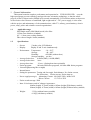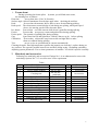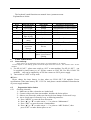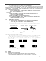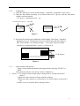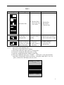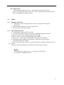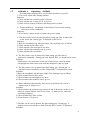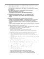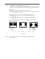
1
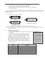
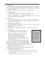
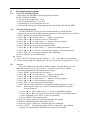
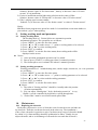
Optical Fiber Fusion Splicer
User Manual
Ver 1.1
Warning (ignore the warning, non-proper use of fusion splicer could lead to fatal
and serious injury)
1. The input voltage of this model of Fusion Splicer is definite; please do not use
the voltage outside the scope. Please use the correct AC and DC power
supply.
2. When the fusion splicer comes across the following failures, please
immediately remove the AC adaptor power cord from the power supply input
and turn off the fusion splicer, otherwise will lead to the incapable of the
repairing and even will cause personal injury, death and fire.
★ Smoke, smell, noise or heat anomaly
★ Liquid or foreign matter enters the interior of the machine
★ Broken or damaged machines
3. This model of fusion splicer does not have the need to maintain internal
components, dismantling of fusion splicer and power modules is prohibited;
any mistake in maintenance will lead to the machine beyond repair even
causing bodily harm.
4. This model of fusion splicer has strictly limitation to the power supply module
used.
5. The fusion splicer is prohibited to be used under the environment with the
inflammable liquid or flammable gas; otherwise will lead to fire, explosion
and other serious consequences.
Notes:
1. This model of fusion splicer is used for the fusion of quartz glass fiber; please
do not use this machine for other usages. Please read this manual carefully
before using.
2. Please do not deposit fusion splicer under the environment with high
temperature or humidity.
3. If the fusion splicer is used in the environment with lots of dust, it should
avoid dust as far as possible.
4. When the fusion splicer moves from the low-temperature environment to
high-temperature environment, heating process must be ensured as possible to
eliminate condensation.
5. In order to maintain fusion splicer’s performance, recommend to do complete
machine maintenance once a year.
6. The fusion splicer has been precision calibrated, please try to avoid strong
vibration, and impact, and use dedicated box for transportation and storage.
l The fusion splicer must be repaired and debugged by specialized technical
personnel, for the appeared problems, please contact the manufacturers in
a timely manner.
2
Optical Fiber Fusion Splicer
User Manual
1
1.1
1.2
General information
Applicable range
Specifications
2
Terms about
3
Main body and accessories
4
Panel and side elevation
5
Operating keys
6
6.1
6.2
6.2.1
6.2.2
6.2.3
6.2.4
6.3
6.3.1
6.3.2
6.3.3
6.3.4
6.3.5
6.3.6
6.4
6.5
6.5.1
6.5.2
6.5.3
Fiber’s fusion flow
Start and stop
Preparation before fusion
Checking electrode
Fixing splice protection sleeve
Making fiber’s end-face
Side elevation of cleaved fiber’s end-face
Fusion
Selecting proper fusion program
Loading fiber
Fusion instance and measure
Auto fusion and estimating loss
Splicing partial core fiber
Evaluating fusion quality
Tension test
Protection of fusion point
Taking out spliced fiber
Moving splice protection sleeve
Heating splice protection sleeve
7
7.1
7.2
7.3
7.4
7.4.1
7.4.2
Explanation about menu
Heating time
Setting end-surface
Tension Test
Splicing fiber and fusion program
Splicing fiber
Fusion program
3
7.5
7.6
7.6.1
7.6.2
7.6.3
7.6.4
7.6.5
7.6.6
7.6.7
7.6.8
Working mode
Maintenance
Cleaning electrode and electrode aging
Sensor initialization
Setting time/date
Arc record
Zero to take count of arc
Splicing record
Language
RS 232
8
8.1
8.2
8.3
8.4
8.4.1
8.4.2
Selecting fusion program
Overview of fusion program
Selecting fusion program
Arc test
Optimization of arc parameter
Optimization of SM fiber’s arc parameter
Optimization of MM fiber’s arc parameter
9
9.1
9.2
Setting working mode and parameter
Setting working mode
Setting working parameter
10
10.1
10.2
10.3
10.4
10.5
Maintenance
Replacing electrode
Maintenance of electrode
Cleaning V-groove
Cleaning lens of microscope
Maintenance of machine
11
11.1
11.2
Notice
Shipping and storing
Operating instructions
12
Addenda A
Operating
13
Addenda B
Explanations about arc test
14
Addenda C
Unusual condition, confirmation and solution
15
Addenda D
Introduction of power supply modules
16
Addenda E
Clean V-groove and fiber
skillfully
4
1 General information
This manual contains complete performance and operation for FUSION SPLICER. uses the
high-speed image process technology and special exact orientation technology, so that the whole
process of fiber’s fusion can be finished in 20 seconds automatically. LCD monitor makes each process
of fiber fusion clear. Because of small bulk, light weight and AC、DC power supply, it is the same
with the project and maintenance of telecommunications, cable TV, railway, petrochemistry, electric
power, army, police and scientific research organizations.
1.1
1.2
Applicable range
SM (Single-mode), MM (Multi-mode) silex-fiber
125µm outer diameter (standard)
0.2~1.5mm outer coating diameter
Fiber cleaved length: 16mm (standard)
Specifications:
· Screen:
5 inches color LCD Monitor
· Display:
Display X and Y axis simultaneously
· Environment: Temperature:
-10~50℃
Storage:
-40~60℃
Humidity:
<95%RH (without dew)
Storage humidity: no dew
· Average fusion loss:
0.02dB (SMF), 0.01dB (MMF)
· Average fusion time:
9secs.
· Average heat time:
30 secs. (Setting heat time optionally)
· Fusion program:
100 units SM fusion programs, 100 units MM fusion programs
· Internal light(setting fiber at night)
· Internal heater
· Setting the parameters: Testing end-face angle, Push distance, Pre-fusion current,
Pre-fusion time, Fusion current, Fusion time etc.
· Power supply(average): Alternating Current: 100-240V 50Hz / 60Hz 30W
Direct Current:
13.5V/5A/ 25W
· Fusion results storage: 5000
· Inner Li-ion battery and AC adaptor Appearance:
180mm (length) x172mm (width) x185mm (height) With battery module;
180mm (length) x172mm (width) x145mm (height) Without battery module;
· Weight:
3.3 Kg (without battery module)
4.1 Kg (with battery module)
5
2. Terms about
During operating the fusion splicer by menu, you will find some terms,
the meanings are as follows:
Heat time:
sets up heat time. (Unit: 30 Seconds)
Surface angle: Allowed maximum cleaved slope angle when checking the end-face.
Push:
Process that electromotor drives fiber to move forward during splicing.
Push speed: The electromotor controls delay of unit during arc splicing, while push speed
slower, the moving speed of fiber becomes faster.
Pre-fusion:
Process that arcs little current while doesn’t push fiber during splicing.
Fusion:
Process that arcs proper current and pushes fiber during splicing.
Fusion push: The quantity of pushing fiber during splicing.
Gap:
Space between left and right fibers’ end-face that set up by before splicing.
Calibration:
Process that adjusts the warp between left and right fiber to make
them are collinear during splicing.
Test:
arcs to revise arc position and arc current automatically.
Cleaning electrode: Part high temperature gasifies the impurity on electrode’s surface during arc.
Arc position: The opposite position between arc and fiber during arcing. (Eyeballing optionally)
Adjusting system parameters: Zero to inner parameters of machine. You needn’t operate it usually.
3 Main body and accessories
Following are main body and accessories: Fittings No.1~6 are admeasured to users with
main body; Options No.7~13 are sell to user’s base requirement.
S/N
1
2
Table 1
Description
Fusion splicer
Power supply modules
3
Carrying case
4
5
6
7
8
9
10
11
12
13
14
Spare electrodes
Cooling tray
AC power cord
Power adaptor
Cleaning Brush
Plastic nipper
Screen cover
User manual CD
Packing List
Certificate and Test report
Warranty Card
Model No.
KL-01-26L7
KL-04-26C
(with belt)
KL-09-26C
DC 13.5/5A
Qty.
1
1
Remark
Main body
Accessories
1
Accessories
1
1
1
1
1
1
1
1
1
1
1
Accessories
Accessories
Accessories
Accessories
Accessories
Accessories
Accessories
Accessories
Accessories
Accessories
Accessories
6
4. Panel and side elevation
Heat Oven
Windshield
Keyboard
P.S Modules
LCD Monitor
Figure 1: The sketch map of main body’s panel
7
Heater
P.S Switch
Out DC power input
RS232 Port
P.S Module
Figure 2:
Figure 3:
Side-View of Main Body
Left and Right keyboards
8
The keyboard’s multi-functions are manual /Auto /parameter menu.
Explanations as below:
Keys
◄
►
▲
▼
FUNCTION
MENU
ENT
HEAT
TEST
START
6
6.1
Manual mode
Scroll left
Scroll right
Scroll up
Scroll down
Shift left/right
fiber driving
Enter/Exit
menu
Invalid
Heat
protection
sleeves
Invalid
Invalid
Auto mode
Invalid
Invalid
Invalid
Invalid
Invalid
Parameter menu mode
Add parameter or move cursor
Add parameter or move cursor
Add parameter or move cursor
Add parameter or move cursor
Invalid
Enter/Exit menu
Enter/Exit menu
Invalid
Heat protection
sleeves
Confirm efficient selection
Heat protection sleeves
Test arc
Enter “Continue” and
pause, press Start to
splicing
Invalid
Invalid
Fiber’s fusion flow
Start and stop
fusion splicer can be supplied by outer battery, inner PS modules or AC adaptor.
Use AC adaptor or outer battery, please connect PS output with “DC 12V/5A”, turn switch to “DC” to start
machine.
1) Use KL-01-26L7 , please turn switch to “ON” to start machine. Use KL-01-26L7, can
be supplied by inner battery or AC PS line connect to 220V PS; Use KL-01-26AC PS
modules, only can be supplied by AC PS line connect to 220V power supply.
2) Turn switch to “OFF” to stop work.
●Notice:
Please charge the inner battery in time when use KL-01-26L7 PS modules. Power
specifications of the inner battery: DC 13.5V/5A. And please consult Addenda D Introduction
of power supply modules.
6.2
6.2.1
Preparation before fusion
Checking electrode
1> Make sure no fiber; electrodes are loaded well.
2> Connect with power then start machine, initialize the fusion splicer.
3> Observe arc electrodes; make sure that no obvious damage on electrode’s top.
4> Arc to check state of electrode’s top, as following measures:
a> Press “MENU” to enter the first class menu.
b> Press “▲” or “▼” to make cursor “→” to point to “Maintenance”.
c> Press “ENT” to enter the menu of maintenance.
d> Press “▲” or “▼” to make cursor “→” to point to “ARC Position”, then
press “ENT” to make fusion splicer to arc.
9
e> Confirm normal; then press “MENU” to exit menu in turn.
5> Electrode aging: If you do not use the machine for long time, in order to assure splicing
quality, please operate “electrode aging” before the first splice, operate process is similar to process
“clean electrode”. “electrode aging” will arc electrode 20 times to clear the layer of oxide on electrode
6.2.2 Fixing splice protection sleeve
To protect joint after fusion, you should enclose the fiber into the splice protection
sleeve. Please consult figures 4 (a).
l Notice:
1> Make sure that there’s no dirt in the splice protection sleeve and surface of
fiber has been cleaned before fixing.
2> Make sure that fiber is in the splice protection sleeve.
3> To avoid influencing fusion’s target, please cut the otiose part if the inside core’s
length is longer than the sleeve’s coat.
6.2.3
Making fiber’s end-surface
1> Strips cover about 30mm~40mm with fiber coat stripper and clean the dirt
of bare fiber with alcohol tampons. Please consult figure4 (b).
2> Cut the bare fiber with fiber cleaver and hold it about 16mm as figure4 (c) shows.
splice protection sleeve
covered fiber
bare fiber
30~40mm
(a)
Figure 3
(b)
covered fiber
bare fiber
16mm
(c)
6.2.4 Side elevation of cleaved fiber’s end-face
The quality of fiber’s end-surface is of influence to fusion loss; you should try to make
end-face flatly, and the inclination between end-surface and section should be less
than 1º. The figure5(a) is finer end-surface for fusion while (b) ~(f) are unqualified and
need to remade.
<1°
(a) the good end-face
(d) the unfilled corner
6.3
6.3.1
(b) the raised tine
Figure 4
(e) the kick
fiber’s end-face
(c) the saw-tooth
(f) the moire
Fusion
Selecting proper fusion program
Change arc program and parameter to obtain the best fusion result due to
different environment and different kinds of fibers (consult 8.2, 8.3, and 8.4).
10
6.3.2
Loading fiber
1> Open the wind cap to reposit the fiber holder; “Load fiber” is displayed on the screen.
2> Open the fiber holder separately ,Load cleaved fiber into V-groove, and the end-surface
couldn’t touch the bottom
of V-groove, consult figure 6(a)、(b).
the bottom of V-groove
bare fiber
(a)
(b)
Figure 5
3> Put down fiber holder and windshield to finish loading. Then figure 7 should be
displayed on screen. The distance between two fibers must less than radius of
fiber. If the distance exceed adjust arrange, won’t splice, then you should
load fiber over again and clean V-groove. (Consult 10.4)
2R
<R
LCD monitor
Figure 6
6.3.3
Fusion instance and measure
Table 2 is the possible phenomena that appeared after pressing “START” or
“TEST”.
If the phenomena don’t exist, please consult <Addenda A>.
☆ Notice: 1> To guarantee fusion target, please setting value of “Setting end-surface”
about 6.
2>Make sure that electrode is fixed well before splicing.
3>Make sure that electrode is well and there’s no obvious injury on electrode’s
top.
4>Best to test arc each time before splicing.2 times.
11
Table 2
Graphic
Message
Reload the fiber
Bad left fiber or
bad right fiber
Reason
1. The bare fiber is
cleaved too long
or too short.
Bad end-surface’s
quality.
1. There is dust in
The picture is clear
V-groove.
in only one direction
or picture are unclear 2. There is dust on
in two directions.
bare fiber.
6.3.4
Measure
1. Reload fiber.
2. Recut fiber.
3. Clean the lens.
1. Remake the end-surface.
2. Reset end-surface’s angle
1. Clean V-groove.
2. Clean bare fiber
3. Reload fiber
Auto fusion and estimating loss
The steps of auto-fusion are as follows:
1) Check and confirm the right option of “fusion fiber”.
2) Consult 6.2.4 and make the end-surface of fiber.
3) Open the windshield and fiber holder to load fiber.
4) Close the windshield, then press “START”, will begin to work automatically:
clean fibers automatically, check end-surface, setup gap, adjust fiber’s core, arc
splice, estimate loss and display loss on screen.
08-10-10
AUTO (SM)
Estibate Loss:
15:30
0.01dB
12
5) If “Not qualified end-surface” or “Reload fiber” is displayed, will stop
working. Please remake fiber’s end-surface or refer table 2. (Consult 6.2.4 and 6.2.5)
☆ Notice: 1> Please do not press “HEAT” after you press “START” and when machine in status of
auto splice, otherwise will have error.
2>Fusion splicer will estimate loss one time only after splicing automatically.
3> Only the electrode is well, arc parameter is optimized, fiber character is
identical, then fusion loss is of reference.
4> Best to arc test before splicing.
6.3.5
Splicing partial core fiber
If loss is unsteady during splicing, the measures are as follows:
1> Check whether the arc is steady and whether the parameter is proper.
2> If opposite position is steady and the parameter is proper, maybe fiber’s core
is partial. The solution is minish the value of “fusion time” and “fusion push”.
3> If method<2> is useless, to obtain best loss, you must mark direction angle on the
fiber to test fiber’s fusion.
6.3.6
Evaluating fusion quality
Fusion quality is judged by estimating loss, fusion shape and fusion process.
Only combine them together, and then the evaluation is external.
1> If fusion process is steady and the spliced fiber’s shape as follows as Table 3,
then the fusion status is well.
Table 3
Fiber’s cord is accord with shape
Spot or abrasion, be care of cleaning and
cleaving end-surface
white
line
Because of optics, there’s no effect to joint
Different eccentricity between two fibers
Different external diameter between two fibers
2>If the spliced fiber’s shapes are as follows as Table 4, you must splice over again even
the loss value is very low.
13
Table 4
Shape
bubble
broken
thin
diameter
Reason
Measure
1. There is dust on the end-face
2. Dew
3. Bad fiber’s end-surface
4. Too small arc current
1. Remake end-surface.
2. Adjust program or current.
(Optimization of arc
1.
2.
3.
4.
Too large arc current
Too small push speed
Little fusion push
Feed blocked
Notice: Black line will appear
black line on fiber’s joint with fluorine,
it has no effect to transport
characteristic.
parameter)
1. Adjust program or current
parameter.
2. Clean V-groove.
(Optimization of arc
parameter)
Press “AUTO” to arc again
and observe.
6.4
Tension test
KL series fusion splicers supply the function of tension test.
If you need this function, when you enter into “MENU”, please open this function, and after each
splicing, machine will do tension test.
After you start the machine, the screen displays as left picture:
08-10-10
You can base need to select “if test
tension”, then operate. After splicing
the screen displays as right picture.
Press “ENT” to make FS-280 to test
tension automatically.
If you don’t want to test tension, then press
“RESET” to reset system after taking out
spliced fiber or do not select “Test tension”.
AUTO (SM)
Proof Ok
Estibate Loss:
15:30
0.01dB
6.5
Protection of fusion point
6.5.1 Taking out spliced fiber
Raise windshield and fiber-collect in turn, take out spliced fiber, do not touch electrode.
6.5.2 Moving splice protection sleeve
Move splice protection sleeve that covered around fiber to joint, make sure that length
of two fiber’s coat is equal in splice protection sleeve. Consult figure 8(a).
6.5.3 Heating splice protection sleeve
The heating processes are as follows:
1> Open heater and put the splice protection sleeve into it.
14
2> Press “HEAT” to heat splice protection sleeve when light is on.
3> After time is up, the light will stop heating automatically.
4> Wait a moment, after splice protection sleeve stiffen, take out it and the joint
protection is finished.
Figure 7(a) and 8(b) are the good examples; 8(c) is the bad example. If the phenomenon as 8(c)
appears you should remake the joint and check whether there is dust in the splice protection sleeve and on
bare fiber, then heat it.
splice protection sleeve bare fiber
covered fiber
(a)
(c)
bad example, have bubbles
l
l
7
(b)
good example, no bubbles
Notice: Please do not press “HEAT” after you press “START” to avoid error.
To avoid damage the heating groove, please do not press it with hard thing whatever heater is in
work condition or not.
Explanation about menu
The most function and parameter are achieved in the menu; the operation methods
08-10-10
15:30
are as follows:
HEATING TIME (1S)
Press “MENU” to enter the first class menu as right picture.
30
CLEAVE ANGLE (0.5.)
Cursor “→” point to the optional or modifiable content,
5
press “▲” or “▼” to move the cursor; The next line’s number
PROOF ENABLE(1ON/2OFF)
2
is value of the item, press “◄” or “►” to modify;
PROGRAME
(1-100)
The modification quantity in the bottom of menu stands for the
6
FIBER (1SM, 2MM)
change quantity of increase/decrease key when modify certain
1
value, you can press “AUTO” to select among “1,10,100”;
SPLICE SELECT (1A, 2M)
1
Press “ENT” to confirm or enter next menu; Press “MENU” to
MAINTENANCE
exit current menu.
Remark:
You must press “ENT” to confirm after modifying the value.
Item
Heat time
Setting end-surface
Tension Test
Current deflection
Fusion program
Fusion fiber
Working mode
Maintenance
Content
Setup heat time of heater on the panel
The maximum cleaved angle when it works
Setting whether test tension after splicing finish
Basic value of arc current (do not change it)
Different fusion program (200 kinds)
SM fiber or MM fiber optionally
Automation or manual optionally
Enter the next maintenance menu
15
7.1
Heating time
The setting range of heating time is 1-60s, step-size is 1S. If heat time is 4, actual heat
time is 4S. Press “HEAT” to turn on the light, then the heater begins to work; heater will
stop working if time is up. But if the temperature were the highest value, it would keep
the temperature regularly.
l Remark: Press “HEAT” to stop heating. Next heat time counts from zero.
7.2
Setting end-surface
Setting end-surface stands for the maximum cleaved angle under auto
work mode. Its setting range is 1~16, step-size is 0.5~8.0°, it
is 6 (3.0°) usually. If the fiber’s cleaved angle is unqualified, the splicer will stop
working and demand to do over the end-face.
7.3
Tension Test
You can select TENSION TEST start or close, “1” means open this function, “2”
means close this function. When tension test opened, machine will do this function
automatically after each splicing.
7.4
Splicing fiber and fusion program
The two parameters can concert each other. You can select 20 kinds different
fusion program (SMF: 100 MMF: 100).
7.4.1 Splicing fiber
Figure 1 stands for selecting SM fiber and figure 2 stands for selecting MM fiber.
7.4.2 Fusion program
2008-10-10
15:30
It stands for the adopted fusion program currently.
The program number is 1~100,inside it is divided to
PREARC POWER (0.1mA)
98
SM1~100 and MM1~100. No.1~No.5 are set by
PREARC TIME (10mS)
factory; you can set program from No.6~No.100
20
ARC POWER (0.1mA)
freely. But will adjust No.6 program after
118
ARC TIME (0.1S)
fusion testing automatically, and setup the No.6
25
program, please consult 8.3-arc test. Press “ENT”
FORWORD SPEED (mS)
6
to enter the program setting menu after selecting program
FORWARD (1μm)
number as right picture.
22
Cursor “→” point to the optional or modifiable content,
press “▲” or “▼” to move the cursor; The next line’s number is
value of the item, press “◄” or “►” to modify; The modification
quantity in the bottom of menu stands for the change quantity of
increase/decrease key, you can press “AUTO” to select among “1,10,100”;
Press “ENT” to confirm or enter next menu;
Press “MENU” to exit current menu.
l Remark: You must press “ENT” to confirm after modifying the value.
The explanations of parameters are as follows:
7.4.2.1 Pre-fusion current and Pre-fusion time
After setting gap and adjusting, begins to work. In the process, the fusion
splicer will pre-manage the fiber. The range of pre-fusion current is 0.1~24mA,
step-size is 0.1mA;
the range of pre-fusion time is 10~1000 mS, step-size is 10mS.
16
7.4.2.2 Fusion current and fusion time
It is the current value and arc time. The range of fusion current is 0.1~24mA,
step-size is 0.1mA; the range of pre-fusion time is 0.1~10S, step-size is 0.1S.
(The value of current can be tested automatically base on the arc testing)
7.4.2.3 Push speed and fusion push
will wrap part fiber in the process of fusion, these two parameters decide
speed of fiber and quantity of wrap. The range of push speed is 1~30mS, step-size
is 1mS; the range of fusion push is 1~100µm, step-size is 1µm.
08-10-10
7.5
Working mode
The manual/Auto mode is optional. “1” is Auto mode and “2” is
manual mode.
15:30
CLR ELECTRODE
OLD ELECTRODE
SENSOR INITIALIZE
DATE&TIME
ARC COUNT INFORMATION
7.6
Maintenance
Cursor “→” point to “Maintenance”, press “ENT” to enter
maintenance menu. It contains daily maintenance and part accessorial
content as right picture. Cursor“→” stands for current selection; Press
“▲” or “▼” to move cursor;
Press “ENT” to confirm; press “MENU” to exit current menu.
7.6.1 Cleaning electrode and electrode aging
The two functions will produce high-pressure arc. Please consult 10.2.
7.6.2 Sensor initialization
Setting the sensor status to make splicing quality better.
7.6.3 Time/date
After enforcing the function, menu will appear as right picture,
and then you can modify date and time of .
Cursor “↓” point to modifiable content, press “◄” or “►” to move
cursor; Press “▲” or “▼” to modify; Press “ENT” to confirm modify
and exit current function. Press “MENU” to exit.
ARC COUNT CLR
MEMORY
LANGUAGE
RS232
08-10-10
15:30
DATE&TIME
↓
2008-10-10
13:30
↓,↑=change
→,←=move
ENT=SELECT
value
cursor
MENU=ESC
7.6.4 Arc record
When machine open this function, the right menu will appeared, so you can check arc amount.
08-10-10
7.6.5
Zero to take count of arc
When you replace with new electrode, you an carry “ Zero to take
Count of arc”, press “ENT” to confirm zero and press “MENU”
To exit.
15:30
0001 2008-10-10
Loss:
0002 2008-10-10
Loss:
0003 2008-10-10
Loss:
0004 2008-10-10
Loss:
10:21
0.01dB
10:23
0.02dB
10:25
0.01dB
10:28
0.01dB
↓↑ (P00004) ↑
↓=N.page↑=L.page
MENU=esc
17
8
Selecting fusion program
8.1
Overview of fusion program
fusion splicer has 200 kinds of fusion program (100 kinds
for SM, 100 kinds for MM).
1> Factory setup program No.1~No.5.
2> Users setup program No.7~No.100.
3> Program No.6 is saved program after test.
4> You should select proper fusion program base actual splice fiber(SM or MM).
8.2
Selecting fusion program
provides function to correct arc current automatically, to satisfy different
requirement; you can select different fusion parameters. The operations are as follows:
1> Press “MENU” to enter the first class menu;
2> Press “▲” or “▼” to make cursor “→” point to “Fusion fiber”.
3> Press “◄” or “►” to select the value of “Fusion fiber”.
4> Press “▲” or “▼” to make cursor “→” point to “Fusion program”.
5> Press “◄” or “►” to select needed arc program.
6> Press “MENU” to enter program parameter menu.
7> Press “▲” or “▼” to make cursor “→” point to modifiable parameter
8> Press “◄” or “►” to increase or decrease the quantity of selected parameter.
9> Press “ENT” to save program parameter after confirming.
10> Press “MENU” to exit menu in turn.
l Notice:
1) Press “AUTO” to modify step-size among “1”, “10”, “100” under two class menu.
2) You can only modify arc program No.6~No.10, but can refer to program No.1~No.5.
8.3
Arc test
The field conditions (such as fiber, altitude, climate, electrode status, etc.) are
influential to splice loss. To get low loss, provides test function to modify
arc current automatically. Operations are as follows:
1> Press “MENU” to enter the first class menu.
2> Press “▲” or “▼” to make cursor “→” point to “Fusion fiber”.
3> Press “◄” or “►” to select the value of “Fusion fiber”.
4> Press “▲” or “▼” to make cursor “→” point to “Fusion program”.
5> Press “◄” or “►” to select needed arc program.
6> Press “ENT” to enter program parameter menu.
7> Check whether fusion parameter is reasonable (consult program No.1~No.5.
Notice: fusion current’s range is 10~16mA). Following methods can modify
current parameter:
a> Press “▲” or “▼” to make cursor “→” point to modifiable parameter.
b> Press “◄” or “►” to increase or decrease the quantity of selected parameter.
c> After confirming, press “ENT” to save arc parameter.
d> Press “MENU” to exit menu in turn.
8> Select two pieces of fiber to be spliced and make end-surface.
9> Raise the windshield and the fiber holder in turn.
10>Load two pieces of fiber into worktable and close windshield.
11>Press “TEST”, will check the quality of fiber’s end-surface, gap, calibrate
cursorily, arc automatically, and then correct value of arc current.
18
12>If “Too large fusion current” or “Too small fusion current” is displayed on the screen,
please repeat step 8~11 until “Right fusion current” is displayed. So test is finished,
and arc program will be rectified to be arc program No.6.
l Notice:
1) The selected fiber must be accord with actual fiber. Best to arc test before splicing.
2) Arc test will correct arc position and arc current, so it is normal if gap position changed
after test.
3) During the process of arc test, if “Proper fusion current” is not be displayed on screen,
please do not enter the parameter menu of the arc program.
4) During the process of arc test, if “Right fusion current” doesn’t be displayed, to avoid
useless current, do not enter splice program parameter menu.
5) During the process of arc test, “Right fusion current” has definite range; you can select
proper arc current base on actual demand.
6) Arc test is efficient only when electrode is well, so you must check electrode at first.
(Consult 6.2.1)
7) The value of “Fusion program” after arc test mustn’t be the best arc parameter due to
consider the factor of “current” only.
8) when pressing "test"button to make splicer arcing for testing,in order to avoid causing errors, don't
press "heat" button,
8.4
Optimization of arc parameter
Those factory-set arc parameters can satisfy splicing of standard fiber basically.
But in order to obtain the best efficiency, it is necessary to optimize arc parameter.
8.4.1
Optimization of SM fiber arc parameter
You need some instruments to test fiber’s loss, for example: lamp-house, OTDR.
The process of optimization of arc parameter is same as process of fusion, you
can use instrument to test loss and change arc parameter properly, until loss is of
coherence and is the smallest. The general principles of optimization of arc parameter are:
1> Increase of current will get similar effect with extending time in definite range.
2> “Pre-fusion current” mustn’t be bigger than “Fusion current”.
3> Do not modify value of “Fusion push”.
4> Best to change value of “Push speed” after selecting current usually.
Notice:
1> Optimization of arc parameter is effective only when arc electrode is well.
2> Fusion loss displayed on screen is of reference only when arc parameter
is well and spliced fibers’ physical parameter is accordant.
l
8.4.2
Optimization of MM fiber arc parameter
Optimization of MM fiber arc parameter is different with SM fiber. The relation
between selection of MM fiber arc parameter and fusion loss is undemanding.
If process of splicing is smooth and splice spot is symmetrical, then loss is
satisfied, and you needn’t to test fusion loss.
Following are general principles of optimization of arc parameter when splicing MM fiber:
1> The value of “Pre-fusion current” mustn’t be bigger than the value of “Fusion current”.
2> The value of “Pre-fusion time” must bigger than splicing SM fiber.
The possible questions and measures are as follows:
1> There is bubble when splicing.
19
Solution: Increase value of “Pre-fusion time”, then try to decrease value of “Fusion
current” if it is insufficient.
2> Fusion is insufficient and the light string is broken in the center of fiber.
Solution: Increase value of “Fusion time” or decrease value of “Fusion current”.
3> Fiber’s splicing spot becomes smaller.
Solution: Try to decrease value of “Pre-fusion current” or value of “Fusion current”.
Notice:
MM fiber fusion program uses special arc mode. It is normal that screen menu shakes or
you can hear “pa pa” when splicing.
9.
Setting working mode and parameter
9.1
l
Setting working mode
The working mode of Fusion Splicer are automatic operation
and manual operation. The operations are as follows:
1> Press “MENU” to enter the first class menu;
2> Press “▲” or “▼” to make cursor“→” point to working mode to be selected;
3> Press “◄” or “►” to select working mode;
4> Press “ENT” to confirm;
5> Press “MENU” to exit the first class menu, then working mode will be
displayed on the screen.
Notice:
1) Auto operation and manual operation can’t be mixed.
2) Best to press “START” to setting gap when it’s manual operation.
3) The fusion splicer won’t estimate loss when it’s manual operation.
9.2
10.
Setting working parameter
Working parameters of include heating time, surface-angle, tension test, etc. The operations
are as follows:
1> Press “MENU” to enter the first class menu;
2> Press “▲” or “▼” to make cursor “→” point to working parameter to be selected.
3> Press “◄” or “►” to select needed working parameter.
4> Press “ENT” to confirm.
5> Press “MENU” to exit the first order menu.
● Notice:
1) The value of “Setting end-face” should be 6 usually under the premise
of fusion automatically.
2) You can adjust “Heating time” freely, the heating control of is very
flexible, it can be controlled by keyboard or reckon through time.
3) “Fusion fiber” must be accord with actual spliced fiber.
Maintenance
10.1 Replacing the electrode
Firstly take off protective cover of electrode room, loosen the screw and take out
up-electrode. Then take out down-electrode in the same way. The installation’s
order of new electrode is opposite to strip. Gap between two tops of electrode should
be within 2.6±0.2mm and they should be symmetrical to fibers. Usually, do not
adjust electrode, and to avoid damage of electrode do not touch the electrode’s
20
top in the whole process, prevent electrode dropping into the machine. After replacing
electrode, you should aging electrode, test the current until it is steady and do the arc test , then you
can continue to splice.
l Notice:
1) Shut off the power of machine before replacing electrode.
2) Make sure that arc parameter had been setup efficiently in the arc process
before testing the arc current.
10.2 Maintenance of electrode
After extended use, the top of electrode will produce dust; dust will make
arc unsmooth. When “hiss” sounds, you should clean electrode. Best
to clean electrode timely as following operations:
1> Turn the switch to“━” to start the machine ;
2> Clean electrode’s top tenderly with alcohol tampons;
3> Press “MENU” to enter the first class menu;
4> Press “▲” or “▼” to make cursor “→” point to “Maintenance”;
5> Press “ENT” to enter maintenance menu;
6> Press “▲” or “▼” to make cursor “→” point to “CLR Electrode”;
7> Press “ENT” to make machine arc automatically, do those two or three
times. To stabilize arc current and clean electrode, the high temperature
will boil off the impurity on the electrode, until arc is stable and the
sound of “hiss” disappear.
8> Press “MENU” to exit menu in turn.
l Notice:
1) Because top of electrode is very weak, to avoid damage of electrode and
unstable arc, do not touch it by hard things.
2) During the process of maintenance, to avoid damage of instrument, do
not arc large current for a long time.
10.3 Cleaning V-groove
The driving range of adjusting core’s direction is only a little micron, fiber’s
picture will departure normal position and couldn’t level if any things exists.
You should clean the V-groove timely as following operations:
1> Open the windshield;
2> Open the fiber holder and fiber clamp;
3> Using the special tool to push several times at the same direction.
☆ Notice:
To avoid damage of V-groove and instrument, do not clean V-groove
with hard thing(knife) and energize on it.
10.4 Cleaning lens of microscope
fusion splicer adopts the working mode of disposal pictures. It is
necessary to keep the lens of microscope cleaning. The operations are as follows:
1> Open the windshield, under the electrode you will find two lens.
2> If any thing exists on lens, dispose it with proper instrument. To avoid of
damage, do not touch lens with hard thing.
3> Wipe lens with a cotton swab soaked with absolute alcohol or air pouch.
4> Wipe lens tenderly with dry cotton swab until it is clean.
21
10.5 Maintenance
This company guarantees to keep fusion splicer in good repair. Do not
open box to repair if any failure exists. To resolve questions in time, please contact
with our technology department at once.
11
Notice
11.1
Shipping and storing
1> fusion splicer is an exact instrument; it must be transported with special
encasement.
2> Do not put fusion splicer in too hot environment.
3> Do not make it dew when storing.
11.2
Operating instructions
1> fusion splicer can only splice silex fiber.
2> To avoid of too high voltage, do not open windshield and touch electrode.
3> Do not touch electrode with hard thing when cleaning.
4> Do not touch V-groove with hard thing when cleaning.
5> Do not use fusion splicer in flammable and explosive environment.
6> Although normal working life of electrode is 3000 times, do not replace
electrode easily if arc is stable.
7> Best to clean electrode about two or three times before splicing, and do the arc test.
l Notice:
Because of the vulnerability, the electrode is not in the range of repair.
Repair
If any failure exists, please send to our agent or factory with
an exact failure explanation at once.
22
12
Addenda A
Operating skillfully
This addendum can help you to resolve some questions by yourself.
1> The screen is dark after starting machine.
Solutions:
1) Check whether the electrical outlet is inserted.
2) Check whether the voltage of P.S. is too low.
3) Check electric quantity of battery and charge battery in time.
2> “Exhausted Battery” is displayed on the bottom of screen after starting
and buzzer works continually.
Solutions:
1) If use battery, charge in time or replace the power supply.
3> The fiber can be reset as normal, but when setting gap, fiber is immovable
on the screen and “Setting gap” is displayed on the screen.
Solutions:
1) Raise the windshield, left and right clamps. The checking steps as follows:
2) Check whether broken fiber exists.
3) Check whether cleaved length is too short.
4) Check whether fiber matches with V-groove.
5) Check whether fiber is tail fiber.
4> The fiber can be reset as normal, but when setting gap, fiber moves
backwards continually, “Setting gap” and “Reload fiber” are displayed on screen.
Solutions:
Maybe there is too much dust on the lens of microscope, clean the aclinic
and upright lens with cotton swab until dust disappears, then try again.
5> The fiber can be reset as normal, but when setting gap, “Setting gap” is
displayed on screen and after a while “Reload fiber” is displayed on screen.
Solutions:
1) Raise the windshield, left and right clamps. The checking steps as follows:
2) Check whether broken fiber exists.
3) Check whether cleaved length is too short.
4) Check whether fiber matches with V-groove.
6> When calibrating automatically, fiber moves up and down, the screen’s
display stops at “Adjust core”.
Solutions:
1) Check whether the position warp between X and Y directions’ surface is less
than1cm. (screen displays size) If not, return to factory to fix, otherwise
operating as follows:
2) Check whether bare fiber is clean.
3) Clean the dust of V-groove.
7>The fiber can be reset as normal, but when setting gap, “Setting gap” is
displayed on screen and after a while “Bad left fiber’s surface” is displayed.
Solutions:
23
1) Observe fiber picture in screen, if the quality of left fiber’s surface is bad,you can
remake surface and try again.
2) Observe fiber picture in screen, if the quality of left fiber’s surface is good,
maybe the value of “Setting surface” is too small, if you want to keep on working
you can increase it.
3) After “Bad left fiber’s surface” is displayed, the screen becomes dark;
Make sure that windshield is covered well.
Raise windshield, check whether the pipe is dent, and then manage it.
8> The fiber can be reset as normal, but the time of auto-fusion is too long.
Solutions: Enter the menu of arc parameter; check whether the setup is
efficient.
9>During arc test, the position of fiber’s gap leans to one side of screen.
Solutions: When the machine tests the arc, it will adjust the position of current and
arc. If the arc on the apparent of electrode were asymmetric, the arc position
would change. If the change was not too much, you can ignore it, otherwise please
mange it:
1) Enter the menu of maintenance, and then operate “Clean the electrode” several times.
10> When arc splicing, do not use the program (1~5).
Solutions: Because of electrode’s aging, biggish change takes place in opposite
position between fiber and arc or operating environment.
1) The condition of electrode’s aging.
Operate “Clean the electrode” if the top of electrode is well.
Replace electrode if the top of electrode is bad. (Consult 10<Maintenance>)
2) Big change takes place in operation environment. Operations are as follows:
1> Do arc test until “Moderate current” is displayed three to five times.
2> Enter splice program the menu of arc parameter, and check the value of arc
current.
3> translation motion(decrease or increase)current (premelting current, splicing
current).
4> Press “ENT” to save after confirming.
5> Press “MENU” to exit menu.
11> When splicing the MM fiber, there is bubble in the process of arc.
Solutions: The difference between fiber’s core and envelope’s refractive index
is too big. Operations as follows:
1> Consult MM fiber’s arc program set by factory (the value of “Fusion
program” is less than 5) and confirm.
2> Do arc test until “Moderate current” is displayed three times.
3> Splice MM fiber; if there is bubble then modify arc parameter.
Operations are as follows:
1) Enter the menu of arc parameter.
2) Increase 1 step size( 10m/s)to the value of “Pre-fusion time”.
3) Splice fiber; increase the value of “Pre-fusion time” until no bubble.
4) Decrease the value of “Pre-fusion current” if no bubble and fiber thins.
24
13
Addenda B
Explanations about arc test
It is necessary to select proper arc fusion program if you want to obtain low
fusion loss. fusion splicer can modify arc current and arc position automatically.
Basic theory:
The gap position of fiber’s surface before arc is L0 and L1,
The gap position of fiber’s surface after arc is L2 and L3. The formula is as follows:
Δ L = (L3-L2) – (L1-L0)
Base on the value of “ΔL”, you can modify the quality of arc current.
The shrinking value of left fiber “ΔL” is gotten from following formula:
ΔL1 = L2 – L0
The shrinking value of right fiber “ΔL” is gotten from following formula:
ΔL2 = L3 – L1
Base on the value of ΔL1 and ΔL2, you can modify gap position to fit the
change of arc position.
arc
L0
L1
(a)
(b)
L2
L3
(c)
arc test chart
Notice:
Arc tests just only change current of arc parameter; you should optimize
the arc parameter.
25
14 Addenda C
Unusual condition, confirmation and solution
Unusual condition, confirmation and solution
Unusual condition
The possible problem
Solution
Remark
All problems
1) After opening 1. The power socket is not 1. Confirm P.S. output
are caused by
the machine, the be put well or P.S. is damaged voltage is about DC
screen doesn’t
2. The P.S. switch didn’t
12~13V. Check whether inner circuit fault
have light;
work well.
polarity is opposite and probably.
After opening the 3. There is short circuit or
mange it.
If you couldn’t
2. Check whether there solve the
windshield, the light fault in the machine.
is something in the
is off (the machine 4. When using the battery,
problems,
machine, then restart.
doesn’t have
voltage is low or polarity is
please sent it
If it doesn’t work,
reaction)
opposite.
to us with
please contact us.
detailed
explanation.
2) After closing the
The windshield is not 1. Reload fiber.
windshield, the image pressed well or the
2. Clean V-groove.
of fiber is dim.
fiber didn’t come into
the V-groove.
3) When pressing
1. The length of cutting
1. The length of
“START” to setting
fiber
cutting fiber is
gap, fiber moved from
should be 16mm.
wrong.
front to behind
2. The fiber holder 2.Push the fiber
doesn’t work well. holder and check
Then “Reload fiber”
is displayed.
whether there is
fault in it , then confirm
its position and manage
it.
1.There is dust on
4). When pressing
Clean lens and two
“START” to setting
the lens or the light. Lights with cotton.
gap, fiber moved to
2. There is dust on
If it doesn’t work, contact
us.
behind, then “Reload reflector.
fiber” is displayed or
fiber moved from left
to right , occasionally
it can splice.
1.There is dust in the 1.Wipe V-groove at
5) Press “START”,
Fiber image of one
V-groove, which
single direction with tool
Side moved vertically, leads to the position
several times.
and could not splice. of fiber is too higher 2.Clean lens, prism
than another side.
and two lights with
2. There is dust on
cleanly cotton several
lens, light or reflector. times.
3. If it doesn’t work,
contact us.
26
6)After splicing,
displayed big loss or
failed splicing.
1. The fiber is dirty,
the end-face is
unqualified, or there is
fault in the cleaver.
2. There is dust on the
lens, light or reflector.
1. The value of
7)Always display
“Setting end-face”
bad fiber end-face of one
is too small.
side.
2. There is dust on the
Lens, lights or
reflector..
3.The light is dim.
4.There is dust in Vgroove or fiber isn’t
put properly.
8)The value of tested
1.The value of “fusion
current is too big or too current” are too large
small.
or too small.
2. Too much
sediment on the
electrode.
3. The relative
position between
fiber and arc has
changed.
4. The storage
battery doesn’t
work well.
5. The environment
has changed.
1.Adjust fiber cleaver,
All problems are
make qualified fiber end- caused by inner
face.
circuit fault
2. Clean the lens,
probably.
reflector and two lightsIf you couldn’t
with cleanly cotton
solve the
several times.
problems,
3. If it doesn’t work,
please sent it
contact us.
to us with detailed
Enter the menu; add the explanation.
value of “Setting endface”. Clean the lens, the
light and the reflector,
clean the V-groove and
try again.
. If it doesn’t work,
contact us.
1. Enter the menu and
clean electrode
several times.
2. Or select “electrodes
aging” and check
whether the arc is
steady.
Then select Program 3
to test arc again.
3. Test the current until
it is proper.
4. If it doesn’t work,
contact us.
27
9) The image position of 1. Too much sediment
on the electrode.
end-face gap leans to one
2. Electrode deflects
side of screen. (The
because of
function can follow the
concussion.
arc position
3. The lens leans to
automatically, if too
unusual position.
much, please adjust it.
4. When testing
current, open the
windshield too
early or touch one
side fiber, this is
because of wrong
judgment of arc
position.
10) After cleaning V1. The groove on the
groove, fiber can’t be put
fiber holder and Vin it well and the image is
groove don’t lie in
unclear.
same line or same
flat.
2. The tail fiber can
not be pressed
tightly.
11) Normal setting gap
and calibration, but
electrode doesn’t arc
during the fusion.
1.Set the current
parameter to zero or
select the program
without setting
parameter.
2. The storage battery
doesn’t work well.
3.When press the
“START” and the
machine is in mode of
auto splice,” HEAT”
is pressed by mistake.
12) There is spark in the
electrode room or
electrode arcs to near
metal.
The environment is
too damp.
1. Enter the menu and
clean electrode
several times.
2. Close machine and
restart after several
minutes, then do arc
test at least three
times.
3. If deflection isn’t
too much, do not
adjust it.
4. Contact us due to
special condition.
1. Open the board,
push the groove
toward to near Vgroove, check
whether the two
grooves lie in same
line and same flat,
then manage it.
2. Reload fiber.
3. If it doesn’t work,
contact us.
1.Enter the menu, check
whether the parameter
setting is normal, if not,
change it to normal
parameter. If this
doesn’t work, please
send it to us to change
the battery.
2. Don’t press” HEAT”
when the “START” is
pressed and the machine
is in mode of auto
splice.
Change to dry
environment.
If it doesn’t work,
contact us.
All problems are
caused by inner
circuit fault
probably.
If you couldn’t
solve the
problems,
please sent it
to us with
detailed
explanation.
28
1. Regard “TEST” as
13) Normal “START”,
fusion key
setting gap and
wrongly.
calibration, but splicing is
2. Too large current.
abnormal.
3. The value of
pushing is too
small or is zero
because of too
high push speed.
4. The board is not
put well.
5. On the right is bad
tail fiber.
14) Normal splicing.
But the value of fusion
loss is too large and
fusion is failing.
15) There is bubble on
the spliced fiber or the
fiber becomes coarse or
tenuous.
1. Check whether
there is fault in
system or there is
dust on the lens or
lights or reflector.
2. The value of
“Setting end-face”
is too large.
3. Open the
windshield before
the test.
1. The end-face of
fiber is unqualified
or there is dust on
it.
2. The setting of
program parameter
is wrong.
1. Confirm the fiber is
in good condition.
2. Enter the menu to
check parameter
setting and set the
proper parameter.
3. Do art test until
current is proper.
Reload fiber, press
“START” to check
the fusion.
If it doesn’t work,
contact us.
Wipe the lens, reflector
and two lights; decrease
the parameter of
“Setting end-face”.
Do arc test until the
current is proper, and
then slice the fiber.
If it doesn’t work,
contact us.
Make sure that the endface is good.
Test current until it is
proper then try again.
If it doesn’t work,
change the value of
“Pre-fusion current,
time” or “Fusion
push”
All problems are
caused by inner
circuit fault
probably.
If you couldn’t
solve the
problems,
please sent it
to us with
detailed
explanation.
29
16) The splicing index is
too large.
(actual measure)
1. There is dust in Vgroove,
2. Improper current
3. The fiber is not
aligned.
4. The electrode
doesn’t work well.
5. Improper setting
of program
parameter.
6. Unqualified endface. The cleaver is
not good.
7. Special fiber.
8. Bad environment.
17) 1>The heat LED
The heat key is
doesn’t work, but it can damaged.
heat; or the index light,
buzzer and heater don’t
work
2> The heat LED and
buzzer work well, but the
heater doesn’t work.
18).Can’t achieve arc in 1. When press the
fusion and current test or “START” and the
something wrong happen. machine is in mode of
auto splice,” HEAT”
is pressed by mistake.
2. When press
“TEST” and the
machine is in arc test,
“HEAT” is pressed by
mistake.
1. Make sure that the
test way is right.
2. Clean the V-groove,
lens or electrode.
3. Select proper
program to arc.
4. Adjust the cleaver.
5. If the splicing index
is too large, change
the value of “Prefusion current” or
“Fusion push”, find
proper program.
6. Make sure that the
wind power is
proper.
7. Press “Heat” several
times, If it doesn’t
work, contact us.
1. Don’t press “HEAT”
when pressing the
“START” and the
machine is in mode of
auto splice.
2. Don’t press “HEAT”
when pressing “TEST”
and the machine is in arc
test.
All problems are
caused by inner
circuit fault
probably.
If you couldn’t
solve the
problems,
please sent it
to us with
detailed
explanation.
30
15
Addenda D
Introduction of power supply modules
1. Introduction of KL-01-26L7 PS modules
KL-01-26L7 PS modules has inner Lithium battery, 11V 6.6Ah. It is fixed on the bottom of
machine with four screws and easy to replace with special design.
1) Check electric quantity of battery and charging mode explanation:
Press “PUSH” to show electric quantity when machine is off. More green lights show more
electric quantity. The red light stands for charging. Please refer to following table:
Electric quantity
Electric quantity
Electric quantity
Electric quantity 1
≥80%
≥60%
≥40%
≥15%
Voltage≥12.2V
Voltage ≥11.8V Voltage ≥11.4 V Voltage ≥11.0V
l Green light or red light open
О Green light or red light off
Electric quantity
≤10%
Voltage ≤11.0V
2) Charge the battery:
Battery is being charged when AC/DC adapter(13.5V /5A ) is inserted no matter how
much is the quantity of battery. Duration of charging is between 3 hours 40 minutes and 40
minutes, depending on the quantity of battery, red lights indicate being charging, green lights
indicate ending of charging.
3) Notice:
A. Please check the electric quantity before using machine and charge in time.
B. Putting the battery in hot environment or into fire is prohibited.
C. Please do not charge the battery in low environment to avoid reduce the working life.
D. Taking down the battery is prohibited.
E. Battery is expendable; please replace it when the machine could not work with green lights on.
F. Please charge the battery in time when you could not start the machine or machine warns. As
shown in photo.
G. Release four screws to take down the PS modules and the PS modules could be charged
separated from main body.
31
16
Addenda E Cleaning of V- groove and Fiber optical
1. Set gap, when two fibers are not vertically aimed, machine shows “ set fiber again” or “ R&L
BAD CLEAVE” ( as the photo)
08-10-10
AUTO (SM)
Estibate Loss:
15:30
0.01dB
08-10-10
AUTO (SM)
Estibate Loss:
15:30
0.01dB
2.
Check and clean V-groove for the first time
Please be careful and don’t push hard while cleaning V-groove. Use cotton swab dipped by
alcohol to brush slightly, use fiber end to clean the dust and make sure there is enough light.
Clean the dust from V-groove so that machine work correctly. Check according priority:
bending of fiber, press board of fiber. Make sure the restrict groove and V-groove of the big
board is in one line, make sure there is no dust in V-groove.
3.
If fibers are still not in the right place, enter “ Manual mode” and press ▲ or ▼ to align
them, then set to “auto mode” again. Make sure the movement of fiber and key-press is in the
same direction.
08-10-10
AUTO (SM)
Estibate Loss:
15:30
0.01dB
08-10-10
AUTO (SM)
Estibate Loss:
15:30
0.01dB
32
Notice: This company’s products are ameliorated continually; modification won’t be informed.
33