1
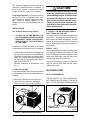
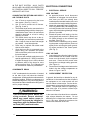
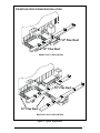
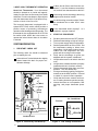
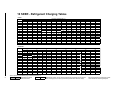
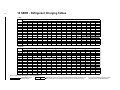
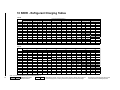
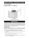
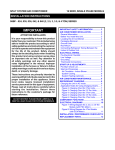
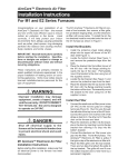
USER'S MANUAL AND INSTALLATION
INSTRUCTIONS
P3B
(A,C) Series 10 and 12 SEER
Single Package Air Conditioner
IMPORTANT
Read this owner information to become familiar with the capabilities and use of
your appliance. Keep this with literature of other appliances where you have easy
access to it in the future. If a problem occurs, check the instructions and follow
recommendations given. If these suggestions don’t eliminate your problem, call
your installing contractor or distributor in your area.
INTRODUCTION
Most any air conditioner will keep you cool. Our air conditioner was designed to
do it efficiently. Efficiency means less cost to you while keeping you comfortable.
WHY YOUR AIR CONDITIONER WORKS SO WELL, SO QUIETLY
1.
Air is cooled by a large evaporator coil. Moisture is also removed from the air by
this same coil.
2.
Air is then delivered through the main duct, via registers, into your home.
3.
Return air is drawn through the return grille.
4.
This air enters the unit, passes through the evaporator coil, is cooled and dehumidified. Then the cycle begins again.
SECTION 1. OWNER
INFORMATION
OPERATING INSTRUCTIONS
To Turn On Air Conditioner
1.
2.
3.
Set the system switch to "Cool."
Set the thermostat at the temperature level
you desire.
Your air conditioner should start as soon as
room temperature rises above the setting
on the thermostat.
To Shut Off Air Conditioner
1.
2.
Turn the system switch to "Heat" or "Off."
Turn the thermostat to the desired heating
temperature setting.
BEFORE YOU CALL A SERVICEMAN
Check your system at the start of each air
conditioning season. Make sure it's working
right, clean or change filters and make any
needed adjustments.
In addition, follow these simple rules:
1. Never run your system without a filter. If
you do, the cooling coils will collect dirt and
may become clogged.
2. Set your thermostat at the comfort level
you wish -- and then leave it alone. Let it
control the operation of the air conditioning
system. If you get chilly, turn it up a degree
at a time until comfort is restored.
3. It takes longer for an air conditioner to cool
your dwelling than it does for your furnace
to heat it. So . . . don't turn the unit on and
expect a dramatic drop in temperature, at
least not right away. If your home is hot and
humid, the temperature will drop slowly.
4. Check your filters every 30 days in summer to see if they are dirty. To keep them
clean, use a mild solution of detergent and
water on washable types. Replace non
washable filters.
5. Keep your outdoor condenser coil clean.
You can hose it down when it gets dirty.
If your air conditioner isn't working:
1. Make sure the fuses are not blown or that
your circuit breakers are on.
2. See that your thermostat is set at the
desired temperature and that your system's
switch is on "Cool."
2
3.
4.
For best air flow, make sure your return
grille is not covered and that the filter is
clean.
Check the outdoor condenser coil and
make sure it is clean and not clogged with
grass or leaves.
If your air conditioner still isn't working, call your
nearest distributor.
SECTION 2. INSTALLER
INFORMATION
GENERAL
Read the following instructions completely
before performing the installation.
These instructions are for the use of qualified
personnel specially trained and experienced in
the installation of this type of equipment and
related system components. Some states require installation and service personnel to be
licensed. Unqualified individuals should not
attempt to interpret these instructions or install
this equipment.
The single packaged air conditioners are designed for outdoor installation only and can be
readily connected into the high static duct
system of a home. The only connections
needed for installation are the supply and return
ducts, the line voltage, and thermostat wiring.
The single package air conditioner is completely assembled, factory wired, and factory
run tested. The units are ready for easy and
immediate installation.
PRE-INSTALLATION CHECK
Before any installation is attempted, the cooling
load of the area to be conditioned must be
calculated and a system of the proper capacity
selected. It is recommended that the area to be
conditioned be completely insulated and vapor
sealed.
The installer should comply with all local codes
and regulations which govern the installation of
this type of equipment. Local codes and regulations take precedence over any recommendations contained in these instructions. Consult
local building codes and the National Electrical
Code (ANSI CI) for special installation requirements.
The electrical supply should be checked to
determine if adequate power is available. If
there is any question concerning the power
supply, contact the local power company.
Inspecting Equipment: All units are securely
packed at the time of shipment and, upon
arrival, should be carefully inspected for damage. Claims for damage (apparent or concealed) should be filed immediately with the
carrier.
! CAUTION:
Do not tip the unit on its side. Oil may
enter the compressor cylinders and
cause starting trouble. If unit has been
set on its side, restore to upright position and do not run for several hours.
Then run unit for a few seconds. Do
this three or four times with five minutes between runs.
INSTALLATION
(For Platinum Series ready homes)
3. INSTALL THE RETURN AND SUPPLY
AIR FITTINGS ON THE UNIT
1.
The supply and return fittings are shipped in the
supply duct. They attach to the unit openings
with a flange and bead arrangement, secured
with two sheet metal screws. Note: For ease of
access, install fitting before positioning unit in
final location.
LOCATE THE 40 AMP BRANCH CIRCUIT DISCONNECT RECEPTACLE AND
DISCONNECT COVER LOCATED OUTSIDE ON ONE OF THE OUTER WALLS
OF THE HOME.
Locate the unit within the reach of the Power
Cord assembly and branch circuit receptacle.
• Create a solid, level position, preferably on a
concrete slab or plastic pad (use NORDYNE
P/N-903897 or equivalent) and slightly above
grade level, located where the skirting channel across top of unit is directly under bottom
edge of wall. (See Fig. 1)
• Minimum clearances to obstructions. (See
Fig. 1)
SUPPLY DUCT
Position the supply duct collar so the edge of the
unit openings fit between the flange and the
bead. Overlap the collar ends keeping the small
screw holes underneath. Align the holes in the
crimped area and install one screw.
Tap collar as necessary to ensure engagement
with unit opening and install second screw.
Tighten first screw.
2. UNPACK THE UNIT
DUCTING SYSTEM
It is recommended that the unit be unpacked at
the installation site to minimize damage due to
handling.
DUCT REQUIREMENTS
a. Remove the bands from around the unit.
b. Unfold the top and bottom cap flanges.
c. Carefully remove the top cap and tube.
6 ft.
24"
THE AIR OUTPUT OF THE SYSTEM WILL
NOT CONDITION THE HOME IF THE AIR IS
LOST TO THE OUTSIDE THROUGH LEAKS
12"
Skirting
Channel
12" Dia.
12"
Dia.
Supply Air
To Main Ducts (2)
36"
12"
Figure 1. Minimum Unit Clearances
Supply Air
From Furnace
14" Dia.
Figure 2. Supply Air Fittings
3
IN THE DUCT SYSTEM. ALSO, DUCTS
WHICH ARE COLLAPSED OR RESTRICTED
BY FOREIGN OBJECTS WILL PREVENT
ADEQUATE AIR FLOW.
CONNECTING THE RETURN AND SUPPLY
AIR FLEXIBLE DUCTS
a.
b.
c.
d.
e.
f.
g.
Use 12” duct to connect unit to the home
duct system. (See Fig. 2 and 3)
Use 14” duct to connect unit to furnace.
(See Fig. 2 and 3)
The flexible ducts can be connected to the
corresponding fittings with the clamps provided with the ducts. Note: All connections
should be leak tight or a loss in cooling
capacity will result.
The flexible ducts may be cut to the required length, see instructions packed with
duct. Keep all ducts as short and straight
as possible. Avoid sharp bends.
Ducts may be spliced with sheet metal
sleeves and clamps.
Once the inner duct is connected to the
proper fitting, the insulation and plastic
sleeve should be pulled over the connection and clamped.
For homes with multiple supply ducts or for
special applications, a Y fitting is available
to divide the supply air so it can be ducted
to different areas of the home for more
efficient cooling. Note: The Y fitting should
be insulated for maximum performance.
CONDENSATE DRAIN
A 3/4” condensate drain connection is located
on the side of the unit below the electrical
compartment. A field supplied condensate drain
should be installed. Route the condensate to a
suitable drainage area. Any connecting tube or
hose must have the outlet below the fitting on the
unit for proper drainage.
! WARNING:
Turn off electrical power before servicing controls. Severe electrical
shock may result unless power is
turned off. Unit must be installed in
compliance with the National Electrical Code (NEC) and local codes.
4
ELECTRICAL CONNECTIONS
1.
ELECTRICAL SERVICE
HIGH VOLTAGE
a. An approved branch circuit disconnect
receptacle of adequate size and disconnect cover per NEC has already been
installed at the intended location of the unit
on one of the four exterior walls of the home.
b. Attach the approved Power Cord/Disconnect Plug (NORDYNE P/N-903899) to the
unit using a strain relief connector (Romex
type or equivalent) through the high voltage
knockout provided.
c. Extend the power cord leads up into the
control panel and connect L1 (Black) and
L2 (White) directly to the contactor lugs
provided. (See Fig. 4)
d. Ground the air conditioning unit by attaching the power cord ground wire (Green-w/
eyelet) to the unit using the green grounding screw provided in the control panel.
(See Fig. 4)
LOW VOLTAGE
a. Low voltage wiring from the indoor furnace
and thermostat will be located under the
home near the branch circuit receptacle
and cover. Route the 24V control wires
through the low voltage sealing grommet.
(See Figure 4)
b. Connect the low voltage control wires to the
leads in the low voltage compartment as
shown in Figure 4 and 5.
2.
OVERCURRENT PROTECTION
In general, the best fuse or breaker for any air
conditioner is the smallest size that will permit
the equipment to run under normal use and
service without nuisance trips. Such a device,
sized properly, gives maximum equipment protection. The principal reason for specifying a
time delay type is to prevent nuisance trips
when the unit starts.
In the event that a fuse does blow or a breaker
trips, always determine the reason. Do not
arbitrarily put in a larger fuse or breaker and do
not, in any case, exceed the maximum size
listed on the data label of the unit.
P3B WITH M1 OR E2 FURNACE INSTALLATION
14" Flex Duct
12" Flex Duct
SINGLE DUCT APPLICATION
14" Flex Duct
12" Flex Duct
MULTIPLE DUCT APPLICATION
Figure 3. Typical Applications
5
Is there free air flow to and from the condenser? A one foot clearance around the
coil, and six foot clearance above the fan?
3. HEAT-COOL THERMOSTAT OPERATION
Heat-Cool Thermostat: Your thermostat
should be located on an inside wall approximately five feet from the floor away from drafts
and doors. Do not locate lamps or other objects
near the thermostat which could affect its operation or block a free flow of air.
The heat-cool thermostat is equipped with a
system HEAT-COOL switch, which provides a
positive means of preventing simultaneous
operation of the heating and cooling mode. The
thermostat is also equipped with an AUTO-ON
fan switch which allows the home owner to
operate the indoor blower when air circulation
is desired.
SYSTEM OPERATION
1.
Is the wiring correct according to the wiring
diagram and electrical codes?
Are all the wiring connections tight? Check
the condenser fan to make sure it turns
freely.
Is the thermostat wired correctly?
installed in a proper location?
2.
START-UP PROCEDURE
a.
b.
c.
d.
Set the system switch to the OFF position.
Dial thermostat setting as high as it will go.
Turn on power supply at the circuit breaker.
Set the system switch to ON or COOL. Set
the temperature setting to below room
temperature. Verify that the indoor blower,
outdoor fan, and compressor are energized and the cooling function starts.
Verify that the discharge air grilles are
adjusted and the system is balanced.
Verify that there are no air leaks in the duct
work.
Verify that the condensate drain is properly
installed and that it functions correctly.
Dial the thermostat higher than room temperature. The unit should stop.
If using a combination heating-cooling thermostat, set to the HEAT position. Proceed
to check for correct furnace operation.
Verify that the furnace controls and burners or heating elements operate correctly.
Instruct the owner on unit operation, filter
servicing, and proper thermostat operation.
PRE-START CHECK LIST
The following check list should be observed
prior to starting the unit.
Is the unit level? It should be level or slightly
slanted toward the drain for proper condensate drainage.
e.
f.
g.
h.
i.
Contactor
Lugs
j.
k.
L2 (White)
L1 (Black)
Is it
Ground
(Green)
Low
Voltage
Connections
Low
Voltage
Entry
Air Conditioner
Furnace
High Voltage Entry
C
BLACK
Y
YELLOW
Condensate Drain
Figure 4. Power Entry and Hook Up
6
Figure 5. Low Voltage Connections
10 SEER - Refrigerant Charging Tables
2 Ton
OUTDOOR TEMPERATURE (°F)
70
75
80
85
90
95
100
105
Suct. Press Dis. Press. Dis. Temp. Dis. Press. Dis. Temp. Dis. Press. Dis. Temp. Dis. Press. Dis. Temp. Dis. Press. Dis. Temp. Dis. Press. Dis. Temp. Dis. Press. Dis. Temp. Dis. Press. Dis. Temp.
71
73
172
174
151
156
188
155
75
176
161
190
160
203
159
77
179
165
192
165
206
164
219
79
183
167
195
169
208
169
221
168
235
167
199
172
211
172
223
173
237
172
251
172
214
176
227
176
239
176
253
176
266
176
85
230
180
242
180
255
180
268
180
282
180
87
234
184
246
184
258
184
270
184
284
183
249
188
262
188
274
188
286
187
265
192
277
281
192
196
290
293
297
192
196
201
81
83
163
89
91
93
95
97
2-1/2 Ton
OUTDOOR TEMPERATURE (°F)
70
75
80
85
90
95
100
105
Suct. Press Dis. Press. Dis. Temp. Dis. Press. Dis. Temp. Dis. Press. Dis. Temp. Dis. Press. Dis. Temp. Dis. Press. Dis. Temp. Dis. Press. Dis. Temp. Dis. Press. Dis. Temp. Dis. Press. Dis. Temp.
69
71
187
189
153
159
203
158
73
191
164
205
163
220
162
75
194
169
208
168
222
167
236
77
197
171
210
172
224
171
238
170
252
170
214
175
227
175
240
175
254
174
269
174
230
179
243
179
257
178
271
178
285
177
83
247
183
260
182
273
182
287
181
301
181
85
250
186
263
186
276
186
289
185
303
185
267
190
280
190
293
190
305
189
283
194
296
300
194
198
309
313
316
193
198
202
79
81
87
89
91
93
95
7
* Note: All pressures are listed in psig. and all temperatures in °F.
- Shaded Boxes indicate
flooded conditions
166
- Rated Design Values. Suction Pressure will be lower than design value if indoor air
flow, entering dry bulb, or entering wet bulb temperatures are lower than design.
- Discharge temperatures greater than charted
values indicate an undercharged system.
8
10 SEER - Refrigerant Charging Tables
3 Ton
OUTDOOR TEMPERATURE (°F)
70
75
80
85
90
95
100
105
Suct. Press Dis. Press. Dis. Temp. Dis. Press. Dis. Temp. Dis. Press. Dis. Temp. Dis. Press. Dis. Temp. Dis. Press. Dis. Temp. Dis. Press. Dis. Temp. Dis. Press. Dis. Temp. Dis. Press. Dis. Temp.
67
69
205
208
167
172
221
171
71
210
177
223
176
237
175
73
212
182
225
181
239
180
252
75
216
185
228
185
241
185
254
184
268
183
232
188
244
189
256
188
270
187
283
187
247
192
259
192
272
192
285
191
299
190
81
263
196
275
196
287
195
301
194
314
194
83
266
199
278
199
291
199
303
198
316
198
282
203
294
203
306
203
318
202
297
207
310
313
207
211
322
325
329
206
211
215
77
79
179
85
87
89
91
93
3-1/2 Ton
OUTDOOR TEMPERATURE (°F)
70
75
80
85
90
95
100
105
Suct. Press Dis. Press. Dis. Temp. Dis. Press. Dis. Temp. Dis. Press. Dis. Temp. Dis. Press. Dis. Temp. Dis. Press. Dis. Temp. Dis. Press. Dis. Temp. Dis. Press. Dis. Temp. Dis. Press. Dis. Temp.
70
72
197
199
157
162
213
162
74
202
168
216
167
229
167
76
203
174
218
172
232
171
246
78
207
177
220
177
234
176
248
176
262
175
223
180
236
181
250
180
264
180
278
180
240
184
252
184
266
184
280
184
294
184
84
256
188
269
188
282
188
296
188
310
188
86
259
192
272
192
285
192
298
192
312
191
276
196
289
196
302
196
314
195
292
200
305
308
200
205
318
321
325
200
205
209
80
82
88
90
92
94
96
* Note: All pressures are listed in psig. and all temperatures in °F.
- Shaded Boxes indicate
flooded conditions
171
- Rated Design Values. Suction Pressure will be lower than design value if indoor air
flow, entering dry bulb, or entering wet bulb temperatures are lower than design.
- Discharge temperatures greater than charted
values indicate an undercharged system.
10 SEER - Refrigerant Charging Tables
4 Ton
OUTDOOR TEMPERATURE (°F)
70
75
80
85
90
95
100
105
Suct. Press Dis. Press. Dis. Temp. Dis. Press. Dis. Temp. Dis. Press. Dis. Temp. Dis. Press. Dis. Temp. Dis. Press. Dis. Temp. Dis. Press. Dis. Temp. Dis. Press. Dis. Temp. Dis. Press. Dis. Temp.
68
70
202
204
162
168
219
169
72
206
173
221
174
236
175
74
208
180
223
179
238
179
253
76
211
182
225
184
241
184
256
185
271
186
229
187
243
189
258
190
273
191
288
192
246
192
260
194
275
195
290
196
305
198
82
264
198
278
199
292
200
307
202
322
203
84
267
201
281
203
295
204
309
206
324
207
285
207
299
209
313
210
326
211
302
213
316
320
214
218
330
334
337
215
220
224
78
80
181
86
88
90
92
94
5 Ton
OUTDOOR TEMPERATURE (°F)
70
75
80
85
90
95
100
105
Suct. Press Dis. Press. Dis. Temp. Dis. Press. Dis. Temp. Dis. Press. Dis. Temp. Dis. Press. Dis. Temp. Dis. Press. Dis. Temp. Dis. Press. Dis. Temp. Dis. Press. Dis. Temp. Dis. Press. Dis. Temp.
58
60
195
197
166
171
212
171
62
199
177
214
176
229
176
64
201
184
216
181
231
181
246
66
204
186
218
187
234
185
249
185
264
185
222
190
236
190
251
190
266
189
281
189
239
194
253
194
268
194
283
193
298
193
72
257
197
271
198
285
198
300
197
315
197
74
260
201
274
202
288
202
302
201
317
201
278
205
292
206
306
206
319
205
295
210
309
313
210
214
323
327
330
210
214
219
68
70
76
78
80
82
84
9
* Note: All pressures are listed in psig. and all temperatures in °F.
- Shaded Boxes indicate
flooded conditions
180
- Rated Design Values. Suction Pressure will be lower than design value if indoor air
flow, entering dry bulb, or entering wet bulb temperatures are lower than design.
- Discharge temperatures greater than charted
values indicate an undercharged system.
10
12 SEER - Refrigerant Charging Tables
2 Ton
OUTDOOR TEMPERATURE (°F)
70
75
80
85
90
95
100
105
Suct. Press Dis. Press. Dis. Temp. Dis. Press. Dis. Temp. Dis. Press. Dis. Temp. Dis. Press. Dis. Temp. Dis. Press. Dis. Temp. Dis. Press. Dis. Temp. Dis. Press. Dis. Temp. Dis. Press. Dis. Temp.
72
74
163
165
137
143
178
141
76
167
148
180
146
192
145
78
170
153
182
151
194
150
207
80
173
156
185
156
196
154
209
153
221
152
188
159
199
158
211
157
223
156
236
155
203
162
214
161
225
160
238
159
250
158
86
217
165
229
164
240
163
252
162
265
161
88
221
169
232
168
243
167
254
166
267
165
236
172
247
171
258
170
269
169
250
176
261
265
175
179
273
276
280
174
178
183
82
84
148
90
92
94
96
98
2-1/2 Ton
OUTDOOR TEMPERATURE (°F)
70
75
80
85
90
95
100
105
Suct. Press Dis. Press. Dis. Temp. Dis. Press. Dis. Temp. Dis. Press. Dis. Temp. Dis. Press. Dis. Temp. Dis. Press. Dis. Temp. Dis. Press. Dis. Temp. Dis. Press. Dis. Temp. Dis. Press. Dis. Temp.
72
74
168
171
142
147
183
147
76
173
152
185
152
198
153
78
175
158
188
157
200
158
213
80
178
160
190
162
202
163
215
163
228
164
194
165
205
167
217
168
230
168
243
169
209
170
220
172
232
173
245
174
258
175
86
224
176
235
177
247
178
260
179
272
180
88
227
179
239
181
250
182
262
183
274
184
242
185
254
186
265
187
276
187
257
190
269
272
191
196
280
284
287
192
197
201
82
84
90
92
94
96
98
* Note: All pressures are listed in psig. and all temperatures in °F.
- Shaded Boxes indicate
flooded conditions
159
- Rated Design Values. Suction Pressure will be lower than design value if indoor air
flow, entering dry bulb, or entering wet bulb temperatures are lower than design.
- Discharge temperatures greater than charted
values indicate an undercharged system.
12 SEER - Refrigerant Charging Tables
3 Ton
OUTDOOR TEMPERATURE (°F)
70
75
80
85
90
95
100
105
Suct. Press Dis. Press. Dis. Temp. Dis. Press. Dis. Temp. Dis. Press. Dis. Temp. Dis. Press. Dis. Temp. Dis. Press. Dis. Temp. Dis. Press. Dis. Temp. Dis. Press. Dis. Temp. Dis. Press. Dis. Temp.
72
74
175
177
128
133
192
135
76
179
139
195
140
210
141
78
180
148
197
145
212
146
227
80
183
151
198
152
214
151
229
152
244
154
201
155
215
157
231
157
246
158
262
160
219
160
233
162
248
163
264
164
279
165
86
237
165
251
167
266
168
281
169
296
170
88
240
169
255
171
269
172
283
173
298
174
258
174
272
176
287
178
300
178
276
180
290
294
182
186
305
308
311
183
188
192
82
84
148
90
92
94
96
98
3-1/2 Ton
OUTDOOR TEMPERATURE (°F)
70
75
80
85
90
95
100
105
Suct. Press Dis. Press. Dis. Temp. Dis. Press. Dis. Temp. Dis. Press. Dis. Temp. Dis. Press. Dis. Temp. Dis. Press. Dis. Temp. Dis. Press. Dis. Temp. Dis. Press. Dis. Temp. Dis. Press. Dis. Temp.
70
72
171
173
152
157
188
155
74
176
162
191
160
206
158
76
179
165
193
165
208
162
223
78
183
168
196
168
210
167
225
165
240
163
200
171
214
171
227
170
242
168
258
166
217
174
231
173
245
172
260
170
275
169
84
234
177
248
176
262
175
277
173
292
172
86
238
181
251
180
265
179
279
177
294
176
255
184
269
183
282
181
296
179
272
187
286
289
185
190
300
303
307
184
188
193
80
82
88
90
92
94
96
11
* Note: All pressures are listed in psig. and all temperatures in °F.
- Shaded Boxes indicate
flooded conditions
160
- Rated Design Values. Suction Pressure will be lower than design value if indoor air
flow, entering dry bulb, or entering wet bulb temperatures are lower than design.
- Discharge temperatures greater than charted
values indicate an undercharged system.
4 Ton
OUTDOOR TEMPERATURE (°F)
7080150
Specifications and illustrations subject to change
without notice and without incurring obligations.
Printed in U.S.A. (4/01)
INSTALLER:
PLEASE LEAVE THESE INSTALLATION INSTRUCTIONS
WITH THE HOMEOWNER.
7080150
¢708015¥¤
12 SEER - Refrigerant Charging Tables
70
75
80
85
90
95
100
105
Suct. Press Dis. Press. Dis. Temp. Dis. Press. Dis. Temp. Dis. Press. Dis. Temp. Dis. Press. Dis. Temp. Dis. Press. Dis. Temp. Dis. Press. Dis. Temp. Dis. Press. Dis. Temp. Dis. Press. Dis. Temp.
64
66
178
181
145
150
194
151
68
183
156
197
156
210
156
70
184
163
199
161
212
161
226
72
187
166
200
167
215
166
228
166
242
204
170
217
171
230
171
244
171
258
172
220
174
233
175
246
176
260
176
274
177
78
236
179
249
180
262
180
276
181
289
181
80
240
183
253
184
265
184
278
185
291
185
256
188
269
188
282
189
293
189
272
193
285
289
193
198
298
301
305
194
198
203
74
76
82
84
86
88
90
* Note: All pressures are listed in psig. and all temperatures in °F.
- Shaded Boxes indicate
flooded conditions
162
167
- Rated Design Values. Suction Pressure will be lower than design value if indoor air
flow, entering dry bulb, or entering wet bulb temperatures are lower than design.
- Discharge temperatures greater than charted
values indicate an undercharged system.