1
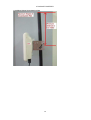
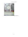
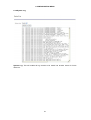
Loop-W8140 Outdoor 2.4G/5.8G Wireless Bridge USER’S MANUAL LOOP TELECOMMUNICATION INTERNATIONAL, INC. 8F, NO. 8, HSIN ANN RD. SCIENCE-BASED INDUSTRIAL PARK HSINCHU, TAIWAN Tel: +886-3-578-7696 Fax: +886-3-578-7695 IMPORTANT NOTE The transmitter module may not be co-located with any other transmitter or antenna. The next nearest transmitter or antenna must be at least 30 meters away. 2011 Loop Telecommunication International, Inc. All rights reserved. Version 2 22 MAR 2011 Table of Contents 1 2 3 4 5 6 7 8 9 PRODUCT DESCRIPTION ........................................................................................... 3 1.1 Description ....................................................................................................... 3 1.2 Features........................................................................................................... 3 1.3 GENERAL PRODUCT SPECIFICATIONS ........................................................ 4 PACKAGE CONTENTS................................................................................................ 8 2.1 Component List ................................................................................................ 8 2.2 Connections...................................................................................................... 9 2.3 Outdoor Enclosure Installation Guide .............................................................. 11 2.4 Earthing Guideline .......................................................................................... 12 QUICK SETUP GUIDE ............................................................................................... 17 3.1 System Requirements for Configuration.......................................................... 17 3.2 Setup Guide ................................................................................................... 17 3.3 LEDs .............................................................................................................. 18 3.4 Factory Default ............................................................................................... 19 BASIC IP NETWORKING........................................................................................... 20 GETTING STARTED .................................................................................................. 22 CONFIGURATION MENU .......................................................................................... 23 6.1 Network ........................................................................................................ 25 6.1.1 IP Settings............................................................................................ 25 6.1.2 SNMP Configuration............................................................................... 28 6.1.3 Protocol Filter Setting............................................................................. 29 6.1.4 QoS ....................................................................................................... 30 6.2 Wireless ....................................................................................................... 31 6.2.1 Basic Settings ........................................................................................ 31 6.2.2 Advanced Settings ................................................................................. 37 6.2.3 Security Setting...................................................................................... 38 6.2.4 Site Survey........................................................................................... 43 6.2.5 MAC Access Control .............................................................................. 44 6.3 Management .................................................................................................. 45 6.3.1 Status .................................................................................................... 45 6.3.2 Statistics ................................................................................................ 46 6.3.3 Miscellaneous ........................................................................................ 47 6.3.4 Performance........................................................................................... 48 6.3.5 Alarm Settings ........................................................................................ 49 6.3.6 Time Settings ......................................................................................... 50 6.3.7 Password Setup..................................................................................... 50 6.3.8 System Log............................................................................................ 51 6.3.9 Firmware Upgrade (for User ADMIN only) .............................................. 52 Troubleshooting........................................................................................................ 53 GLOSSARY ............................................................................................................... 54 DISCLAIMER ............................................................................................................. 55 i List of Figures Figure 1-1 W8140................................................................................................... 3 Figure 2-1 Components......................................................................................... 8 Figure 2-2 PoE (Power over Ethernet) Power Supply .......................................... 9 Figure 2-3 Pin Identification.................................................................................. 9 Figure 2-4 Network Connection ............................................................................ 9 Figure 2-5 Antenna Alignment............................................................................ 10 Figure 3-1 LEDs................................................................................................... 18 List of Tables Table 2-1 PoE (Power over Ethernet) Power Supply Device Pinout.................... 9 Table 3-1 LEDs Status......................................................................................... 18 Table 6-1 User name and Password ................................................................... 23 Table 6-2 Signal Strength.................................................................................... 43 ii 1 PRODUCT DESCRIPTION 1.1 Description The Loop-W8140 is an Outdoor WLAN for WLL (wireless local loop) which is a cost effective solution addressing triple play services (voice, video and data) for home and enterprise access point, and gateway applications. It is suited for point to point and point to multi-point applications. The W8140 comes in an industrial grade (IP67), rugged, cast plastic casing and is designed with mobility in mind. It can also be used in moving vehicles where reliable, long haul wireless communication is critical. Figure 1-1 W8140 1.2 Features General Industrial grade IP67 rugged, cast plastic casing 2.4G/5.8G Dual mode AP Mode selectable: AP, Client, Bridge: Master Bridge, Slave Bridge, Repeater Bandwidth control with QoS, and video, voice and data scheduling Wireless Distribution System (WDS) VLAN tag QoS Support Protocol filtering for Internet and Intranet networks Up to 250 associations and 50 concurrent users Wireless isolation between wireless clients Web and SNMP management Support up to 4 E1 transmission Standards Wireless: IEEE802.11a/b/g/n Ethernet: IEEE802.3, 802.3u (CSMA/CD) RoHS compliant IEEE802.11a/b/g/n IEEE 802.11a/b/g compliant up to 54 Mbps 100/500 mW output power transmission Channel bandwidth adjustable 5/10 MHz for a/b/g only Up to 108 Mbps data rate in Turbo Mode Up to 25 Km range with external antenna LOS (Line of Sight) 3 1.3 GENERAL PRODUCT SPECIFICATIONS Ethernet Functions Ethernet Port 10/100 Base-T (RJ-45 connector) with auto MDIX Management Functions Web-based management System Load Default System status report Association Client List SNMP V1 and V2c Auto Associate to IP with same ESSID DHCP Client, Auto Negotiate for IP IP address discovery software (Viper Quick Start) Future option Firmware can be upgraded through web-server and Telnet Number of client associations AP mode: 250 Number of concurrent users AP mode: 50 Repeater mode: 30 Number of Wireless uplinks Repeater mode: 1 Password Access control to configuration 2 Levels Ping from Device Through Telnet Security and Access Control Static WEP MAC Access Control List Remote AP MAC Control WPA, 802.1x Support WPA-PSK Configuration file download (Telnet) Save last good Setting Software Reset Software Factory Reset Multiple FTP Pass Through VLAN Tag Max 152 bits In AP mode only PassPhase with TKIP and AES ciphers EAP-TLs, EAP-TTLS, EAP-GTC in access point mode *Note: When this feature is enabled, the data bandwidth is set, and the balance of bandwidth will be used for live data such as video and VoIP packets. Bandwidth Limiting with QoS* (priority for UDP over TCP data) 802.11e QoS (priority for Voice and Multimedia) For AP Mode Wireless Client to Client Isolation Suppress SSID Enable, Disable, Disable with multiple clients behind CPE WDS (Wireless Distribution System) Electrical Power adapter Power consumption 18~48V DC through RJ45 Typical 8.5 Watts (Maximum 9 Watts) Physical and Environmental Dimensions Weight Power Requirement Antenna Connectors Power Over Ethernet (PoE) Operating Temperature Relative Humidity when operational Relative Humidity during storage Wind Speed Support 121.3 mm x 214.2 mm x 46mm (WxHxD) 1.2Kg, module only Maximum 11 Watts Two (2) 50 ohm, N-type (female) Passive PoE, non-3af compliant -20°C to +60°C 20% to 90% (non-condensing) Max. 95% (non-condensing) 160 Km/hr. 4 Standards and Compliances IEEE Wireless Standard IEEE Ethernet Standard Waterproof Rating Random Vibration Shock Drop Salt Fog Solar Radiation Safety EMC and RFI ESD Lightning Protection at Ethernet Port Certification 802.11a/b/g/n 802.3, 802.3u (CSMA/CD) IP67 IEC-68-2-64 IEC-68-2-29 IEC-68-2-32 IEC-68-2-11 IEC-68-2-5 EN 60950 FCC Part 15 C IEC 61000-4-2 FCC *Future option Loop-W8140-a/b/g-500mW PRODUCT SPECIFICATIONS RF (Radio Frequency) Specifications Frequency Maximum Data Rate with Auto Fall Back Wireless Data Rate Channels Channel Frequency Step Size Best Channel Scanning at Power up Radio Channel Select Radio Power Control (3dB steps) Transmitter Output Power Modes Supported Nominal Antenna Port Impedance Media Access Protocol Modulation Technique Max distance (With suitable antenna) Antenna Type 2.4 GHz: 2412 to 2484 MHz or 5.8 GHz: 4900 to 5825 MHz (software configurable) 108 Mbps 54, 48, 36, 24, 12, 11, 9, 6, 5.5, 2, 1 Mbps, 108 Mbps for Turbo mode 12 channels (USA/Canada), 13 channels (Singapore, Europe except France),14 channels (Japan) 5 MHz AP Mode only Determined by AP 5 level from Max Up to 27 dBm AP, Repeater, Bridge, Client 50 ohms x 2 (for external antenna connector, if applicable) CSMA/CA with ACK (Carrier Sense Multi-point Access/Collision detection with acknowledgement) DSS, DBPSK, DQPSK, CCK, OFDMBPSK, QPSK, 16QAM, 64QAM Up to 25 Km, point to point 1 ports for receive diversity, Tx/Rx & Rx OPERATING FREQUENCY 2412MHz-2462MHz (2.4 GHz) 11b/g TX POWER SPECIFICATIONS Data Rate Avg. TX Tolerance 1-24Mbps 27 dBm +/-2dB 36Mbps 24 dBm +/-2dB 48Mbps 23 dBm +/-2dB 54Mbps 22 dBm +/-2dB 11b/g OPERATING FREQUENCY 11a RX SPECIFICATIONS Data Rate Sensitivity 1-24Mbps -90 dBm 36Mbps -76 dBm 48Mbps -73 dBm 54Mbps -70 dBm Tolerance +/-3dB +/-3dB +/-3dB +/-3dB 5475MHz-5825MHz (5 GHz) TX POWER SPECIFICATIONS Data Rate Avg. TX Tolerance 1-24Mbps 22 dBm +/-2dB 36Mbps 20 dBm +/-2dB 48Mbps 19 dBm +/-2dB 54Mbps 18 dBm +/-2dB 11a 5 RX SPECIFICATIONS Data Rate Sensitivity 1-24Mbps -90 dBm 36Mbps -76 dBm 48Mbps -73 dBm 54Mbps -70 dBm Tolerance +/-3dB +/-3dB +/-3dB +/-3dB Loop-W8140-MIMO-a/b/g/n-250mW PRODUCT SPECIFICATIONS* Frequency Wireless Data Rate Channels country code setting Best Channel Scanning at Power up Radio Channel Select Radio Power Control (3dB steps) Transmitter Output Power Modes Supported Nominal Antenna Port Impedance Media Access Protocol Modulation Technique Max distance (With suitable antenna) Antenna Type 2.4 GHz: 2412 to 2484 MHz or 5GHz: 4900 to 5825 MHz (software configurable) Up to 300 Mbps 802.11bg 802.11a FCC FCC49 Japan CE Europe China China AP Mode only Determine by AP 5 level from Max Up to 24 dBm AP, Repeater, Bridge, Client 50 ohms x 2 (for external antenna connector, if applicable) CSMA/CA with ACK (Carrier Sense Multi-point Access/Collision detection with acknowledgement) DSS, DBPSK, DQPSK, CCK, OFDMBPSK, QPSK, 16QAM, 64QAM Up to 25 Km, point to point 2 ports for receive diversity, Tx/Rx & Rx OPERATING FREQUENCY 2412MHz-2462MHz 11b/g 11n 2.4GHz TX POWER SPECIFICATIONS Data Rate Avg. TX Tolerance 1-24Mbps 24 dBm +/-2dB 36Mbps 22 dBm +/-2dB 48Mbps 20 dBm +/-2dB 54Mbps 19 dBm +/-2dB 20M MCS0@ 6Mbps 20M MCS1@9Mbps 20M MCS2@ 12Mbps 24dBm 24dBm 24dBm +/-2dB +/-2dB +/-2dB 20M MCS3@ 18Mbps 20M MCS4@ 24Mbps 20M MCS5@ 36Mbps 20M MCS6@48Mbps 20M MCS7@54 Mbps 40M MCS8@ 6Mbps 40M MCS9@9Mbps 40MMCS10@ 12Mbps 40M MCS11@ 18Mbps 40M MCS12@ 24Mbps 40M MCS13@ 36Mbps 40M MCS14@48Mbps 40M MCS15@54 Mbps 22dBm 22dBm 22dBm 18dBm 15dBm 24dBm 24dBm 22dBm 20dBm 20dBm 17dBm 17dBm 15dBm +/-2dB +/-2dB +/-2dB +/-2dB +/-2dB +/-2dB +/-2dB +/-2dB +/-2dB +/-2dB +/-2dB +/-2dB +/-2dB 11b/g 11n 6 2.4GHz RX SPECIFICATIONS Data Rate Sensitivity Tolerance 1-24Mbps -97 dBm +/-3dB 36Mbps -90 dBm +/-3dB 48Mbps -86 dBm +/-3dB 54Mbps -84 dBm +/-3dB MCS0 MCS1 MCS2 -97 dBm -96 dBm -93 dBm +/-3dB +/-3dB +/-3dB MCS3 MCS4 MCS5 MCS6 MCS7 MCS8 MCS9 MCS10 MCS11 MCS12 MCS13 MCS14 MCS15 -91 dBm -87 dBm -84 dBm -78 dBm -75 dBm -96 dBm -94 dBm -91 dBm -88 dBm -85 dBm -80 dBm -79 dBm -76 dBm +/-3dB +/-3dB +/-3dB +/-3dB +/-3dB +/-3dB +/-3dB +/-3dB +/-3dB +/-3dB +/-3dB +/-3dB +/-3dB OPERATING FREQUENCY 11a 11n 5GHz TX POWER SPECIFICATIONS Data Rate Avg. TX Tolerance 1-24Mbps 24 dBm +/-2dB 36Mbps 22 dBm +/-2dB 48Mbps 20 dBm +/-2dB 54Mbps 19 dBm +/-2dB 20M MCS0@ 6Mbps 20M MCS1@9Mbps 20M MCS2@ 12Mbps 20M MCS3@ 18Mbps 20M MCS4@ 24Mbps 20M MCS5@ 36Mbps 20M MCS6@48Mbps 20M MCS7@54 Mbps 40M MCS8@ 6Mbps 40M MCS9@9Mbps 40MMCS10@ 12Mbps 40M MCS11@ 18Mbps 40M MCS12@ 24Mbps 40M MCS13@ 36Mbps 40M MCS14@48Mbps 40M MCS15@54 Mbps 24dBm 24dBm 24dBm 22dBm 22dBm 22dBm 18dBm 15dBm 24dBm 24dBm 22dBm 20dBm 20dBm 17dBm 17dBm 15dBm 5475MHz-5825MHz 11a +/-2dB +/-2dB +/-2dB +/-2dB +/-2dB +/-2dB +/-2dB +/-2dB +/-2dB +/-2dB +/-2dB +/-2dB +/-2dB +/-2dB +/-2dB +/-2dB 11n 7 5GHz RX SPECIFICATIONS Data Rate Sensitivity Tolerance 1-24Mbps -96 dBm +/-3dB 36Mbps -95 dBm +/-3dB 48Mbps -94 dBm +/-3dB 54Mbps -91 dBm +/-3dB MCS0 MCS1 MCS2 MCS3 MCS4 MCS5 MCS6 MCS7 MCS8 MCS9 MCS10 MCS11 MCS12 MCS13 MCS14 MCS15 -97 dBm -96 dBm -93 dBm -91 dBm -87 dBm -84 dBm -78 dBm -75 dBm -96 dBm -94 dBm -91 dBm -88 dBm -85 dBm -80 dBm -79 dBm -76 dBm +/-3dB +/-3dB +/-3dB +/-3dB +/-3dB +/-3dB +/-3dB +/-3dB +/-3dB +/-3dB +/-3dB +/-3dB +/-3dB +/-3dB +/-3dB +/-3dB 2 PACKAGE CONTENTS 2 PACKAGE CONTENTS 2.1 1. 2. 3. 4. 5. 6. Component List Loop-W8140 mounting bracket (pole) screws clamps washers, nuts, U-bolt waterproof RJ 45 adaptor Figure 2-1 Components Note: Standard package may vary with model type and country. Using a combiner adaptor with a power rating other than the one included in the package will cause serious damage to the Access Point and void the warranty for this product. 8 2 PACKAGE CONTENTS 2.2 Connections PoE (Power over Ethernet) Connection An extremely compact device, the Power Over Ethernet (PoE) provides Ethernet only services through one Ethernet port. The PoE power supply device is shown in the figure below. Figure 2-2 PoE (Power over Ethernet) Power Supply Figure 2-3 Pin Identification Pinout values for the PoE power supply are listed in the table below. They are also printed on the back of the PoE unit. Pin ID LAN + DC Pinout LAN Pinout 1 Ethernet Ethernet 2 Ethernet Ethernet 3 Ethernet Ethernet 4 Power+ 5 Power+ 6 Ethernet Ethernet 7 Power8 PowerTable 2-1 PoE (Power over Ethernet) Power Supply Device Pinout Network Connection Figure 2-4 Network Connection 9 2 PACKAGE CONTENTS Installing the access point to your Network Please follow the following instruction to build the network connection between your new wireless access point and your computers, network devices: 1. Connect the access point to ADSL modem, router, or switch/hub in your network through the DATA IN port of the access point by Ethernet cable. 2. Connect the power adapter to the wall socket, and then connect it to the ‘Power’ socket of the PoE. 3. Connect the access point and the PoE through P+DATA OUT port. 3. Please check the LEDs of W8140. ‘PWR’ LED should be steadily on, LAN LED should be on if the access point is correctly connected to the ADSL modem, router or switch/hub. Antenna Alignment Some models of the Loop-W8140 have a built-in antenna. Others use exterior antennas. Regardless of antenna type, there must be line of sight alignment between the antennas. Figure 2-5 Antenna Alignment 10 2 PACKAGE CONTENTS 2.3 Outdoor Enclosure Installation Guide Figure 2-6 Clamp Type Installation Steps 11 2 PACKAGE CONTENTS 2.4 Earthing Guideline 2.4.1 Mounting Bracket One of the screw holes is ODU grounding point. The whole bracket is grounding point after mounted to ODU. Please refer to photo below. 12 2 PACKAGE CONTENTS 2.4.2 When Using Conductive Pole 13 2 PACKAGE CONTENTS 2.4.3 When Using Unconductive Pole 14 2 PACKAGE CONTENTS 15 2 PACKAGE CONTENTS The another end of Earth Cable must connect to Building Earth point. 16 3 QUICK SETUP GUIDE 3 QUICK SETUP GUIDE 3.1 System Requirements for Configuration Computers with Windows, Macintosh or Linux-based operating systems and with an Ethernet adaptor Internet Explorer version 5.5 and above or Netscape Navigator that supports Java 3.2 Setup Guide Step 1: Set default LAN IP address The default LAN IP address is 192.168.1.20. Step 2: Set password The default login name is ADMIN, the default password is LOOP. The user name and the password are case sensitive. . Step 3: Configuring AP Step 3.1: Set IP configuration-IP Settings This page allows you to choose the type of IP 17 3 QUICK SETUP GUIDE Step 3.2: Set operation mode-Basic Settings This page allows you to set the outdoor as an Access Point or an Ethernet Bridge or a Repeater. Step 4: Set security settings This section allows you to configure wireless encryption to prevent unwelcome parties from reading your traffic. Step 5: Reboot the AP Reboot the system to make all the settings take effect. Note: For detailed setup, see sections 5 and 6. 3.3 LEDs Figure 3-1 LEDs Name PWR LAN WLAN Status Function Green Power on operating Off Power off or power fail Green Link up Flashing Green Active Off No Ethernet connection or link fail Green RF function active Off RF function fail Table 3-1 LEDs Status 18 3 QUICK SETUP GUIDE 3.4 Factory Default No Item to Set W8140-AP 1 Device Mode AP mode 2 ESSID W8140 3 WEP None 4 User ID (for configuration) OPERATOR 5 Password (for configuration) LOOP 6 Remark IP ADDR: 192.168.1.20 Default static IP address and subnet Enable Subnet : 255.255.255.0 Default gateway: 0.0.0.0 7 DHCP client Disable With “Static IP” set on 8 DHCP server Disable Support address 192.168.1.1~192.168.1.100 9 Radio Power 100% configurable 10 Radio Frequency 165 AFS enable on power on stage 11 Radio data rate Auto 12 Super User ID (for firmware upgrade) ADMIN 13 Password for Super user LOOP 19 configurable 4 BASIC IP NETWORKING 4 BASIC IP NETWORKING IP = Internet Protocol IP stands for Internet Protocol. In an IP network, every device has a unique IP Address to identify itself. There are two ways of assigning an IP address to a PC or Router: Static and Automatic (DHCP). Static IP addresses are keyed-in manually, while Dynamic IP’s are distributed by a DHCP Server. Ports Every packet of traffic is identified by its Source and Destination Addresses, which would ensure that the packet arrives at the correct destination. A Port Number is also embedded in each packet; to identify which software application that generated and uses that packet. Therefore, if it blocks a certain port number, it denies the particular software from using the connection. Static IP Address Static IP addressing ensures that the device will always have the same IP address. Static addressing is commonly used for your servers. Dynamic IP Address A dynamic IP address is one that is automatically assigned to a PC. These IP addresses are “dynamic” because they are only temporarily leased to the PC when it connects to the network. This is the most convenient and common way of managing IP addresses in a network. The Server that manages this pool of IP addresses is called the DHCP Server. DHCP (Dynamic Host Configuration Protocol) The PC obtaining an IP address from the Server is called the DHCP Client. If there is already a DHCP Server running on your network, you must disable one of the two DHCP servers. Running more than one DHCP server together will cause network problems! Wireless LAN Basics A Wireless LAN (WLAN) is a computer network that transmits and receives data with radio signals instead of using cables. WLANs have become common in homes, offices, airports and public Hotspots. WLAN can support the same applications and software that run on a wired network (LAN). Besides supporting the same software and functions, WLAN brings greater convenience and eliminates the need to lay Ethernet cables in a home or office. The AP can even support 108Mbps wireless data rate at Turbo mode. This is only applicable for user using recommended Turbo-capable Cardbus (with Atheros chipset). WLAN networking involves a few additional parameters to be configured. SSID The SSID is the “network name” for the WLAN network. The SSID is any name, and can be any set of characters or numbers. The Client sniffs the radio frequencies for an AP with the same SSID with itself. The client locks onto the AP and they are “associated”. To enable plug-and-play convenience, most client cards can sniff the frequencies to extract the available SSIDs to let the user choose from. Encryption WLAN traffic can be captured by anybody to be read! The solution is to use encryption to make the traffic appear as random characters to the eavesdropper. Both the AP and client must use the same encryption standard and key to enable them to decode the “rubbish”. If the encryption settings are mismatched, the client and AP cannot associate. WEP (Wired Equivalent Privacy) is the most common WLAN encryption standard. Channel The frequency is selected by AP or by Master mode, and the frequency of Client or Slave mode should follow AP or Master mode. Or you could selected auto channel to search the frequency. 20 4 BASIC IP NETWORKING Signal Strength Radio signals drop in power over a distance. Even if all the settings are correct, low signal strength makes association impossible. The usable distance between the AP and client can range from a few meters indoor to a few km. When setting up the client, make sure that you: Keep at a distance between the AP and the clients. Make sure that the WLAN signals do not have to pass through too many concrete walls and metal structures to reach the client. Make sure that client(s) is (are) located far away from one another to avoid interference. Make sure that there is line of sight between the AP and client device. Interference Interference happens when 2 clients with the same channels are placed near to one another. The speed of the network drops and the signal strength fluctuates wildly. MIMO In radio, multiple-input and multiple-output, or MIMO is the use of multiple antennas at both the transmitter and receiver to improve communication performance. It is one of several forms of smart antenna technology. 21 5 GETTING STARTED 5 GETTING STARTED Connect the network as shown previously. Note: If your PC is wireless, check the card utility of the PC to make sure that the signal strength is good and that the bottom LED lights up on the AP. Open a Web browser (Internet Explorer, Netscape etc.). Type the AP LAN IP (192.168.1.20) address into the browser’s Address field. The default LAN IP address is 192.168.1.20. 22 6 CONFIGURATION MENU 6 CONFIGURATION MENU All functions and settings of this access point must be configured via web management interface. Please start your web browser, and input “192.168.1.20” in address bar, then the following message should be shown: User name Password ADMIN LOOP OPERATOR LOOP Table 6-1 User name and Password Note: User ADMIN could upgrade firmware but user OPERATOR could not. 23 6 CONFIGURATION MENU After you log in, you can see the web management interface of this access point. After you connected to the access point by web browser, the first page you see is “Status”. All system and network related information of this access point will be displayed here. The information is very helpful when you want to know the detailed information of your access point, and when you try to fix the communication problem between this access point and other wired / wireless computer / devices. 24 6 CONFIGURATION MENU 6.1 Network 6.1.1 IP Settings In every Web Configuration page, the left panel is the navigation menu containing the main sections. The right-side frame is where the detailed configuration is done. This page allows you to choose the type of IP. Static IP Mode: When you boot up the W8140 for the first time, it is in Static mode. You assign a Static IP to the device. The default IP address, subnet mask and gateway are 192.168.1.20, 255.255.255.0 and 0.0.0.0. DHCP Server: If you choose Enable for DHCP Server, please assign the DHCP Client IP Range, DHCP Client MAX Leases, and DHCP Client Lease Time to the device. If you choose Enable for DHCP Server, you could click on to show assigned clients. 25 6 CONFIGURATION MENU DHCP Relay: If you choose Enable for DHCP Relay, please assign the DHCP Server IP (Relay) to the device. 26 6 CONFIGURATION MENU Dynamic IP Mode (DHCP Client): If the Dynamic IP is chosen, the W8140 will obtain an IP Address from an upstream DHCP Server. IP Alias: If you choose Enable for IP Alias, please set Alias IP and Alias IP Subnet Mask for the device when DHCP Client selected. 27 6 CONFIGURATION MENU 6.1.2 SNMP Configuration Device Name: Displays the name of the device. Read Community: The SNMP Client with this “passphrase” will have “Read” access. Write Community: The SNMP Client with this “passphrase” will have “Write” access. Trap IP: The destination IP address to send trap information of the device. You can send trap information to the 2 different destination IP addresses. Trap Community: The device, SNMP agent, have the same string of SNMP Manager will be allowed all traps or authenticated traps by SNMP Manager but also on your device you have to specify a trap destination IP. System Contact: To set the MIB2 system Contact OID value. System Location: To set the MIB2 system Location OID value. 28 6 CONFIGURATION MENU 6.1.3 Protocol Filter Setting Filter IPX Packet: Selecting Disable to control IPX packets to pass through. Wireless Isolation: Selecting this option will control wireless clients associated with this device to communicate with each other. PPPOE Exclusive: Selecting Disable to control PPPOE to pass through. Telnet Access: Selecting this option will control telnet access. Broadcast Rate Control: Selecting this option will control broadcast rate. Maximum Throughput: Select a number in from 10 to 200 (packets/sec.). Multicast Rate Control: Selecting this option will control multicast rate. Maximum Throughput: Select a number in from 10 to 50 (packets/sec.). Rate Limit (for TCP only): Selecting this option will limit the rate on TCP. Rate: Select a number in to set the rate from 10 to 5000 (packets/sec.). Note: For description for acronym, please refer to Glossary. 29 6 CONFIGURATION MENU 6.1.4 QoS Action: Choose to enable the action. Priority: Select from 0 to 9 of priority. 0 is the top priority. Filter Rule: Available options are: all, tcp, udp, ftp, http, voip, ssh, smtp and telnet. Max Rate: Select a number for max rate. Min Rate: Select a number for min rate. Source IP Range: Select the IP range from 0.0.0.0 to 255.255.255.255 for all, udp, and tcp filter rules. Source Port: Select the source port from 0 to 65535 for all, udp, and tcp filter rules. Destination IP Range: Select the IP range from 0.0.0.0 to 255.255.255.255 for all, udp, and tcp filter rules. Destination Port: Select the destination port from 0 to 65535 for all, udp, and tcp filter rules. Note: In this case, enabled udp of filter rule for the first priority. Set the rate between 100 and 204800. IP range set between 192.168.1.2 and 192.168.1.20. Set Source port and destination port 23 to 23. Destination IP range set between 192.168.1.21 and 192.168.1.31. 30 6 CONFIGURATION MENU 6.2 Wireless 6.2.1 Basic Settings This access point can be operated in different modes; you can click “Basic Setting” on the left of web management interface to select an operating mode you want to meet for different need: 6.2.1.1 Operation mode: AP Band: a/b/g Band: You can choose 5G 11A, 5G 11 Turbo A, 2.4G 11B, 2.4G 11G, 2.4G 11 Turbo G. Please select the wireless band you wish to use. By selecting different band setting, you’ll be able to allow or deny the wireless client of a certain band. Channel: There are different channels list choose able. You can choose to set the frequency channel to use or use Auto for automatic channel selection. Mode: AP The AP can be used as an Access Point or as a Client (Ethernet Bridge). SSID: Service Set Identifier (SSID) is a sequence of characters that uniquely names a Wireless LAN. This name allows PCs to connect to the correct Wireless Access Point when multiple Access Points operate in the same location. The default SSID is W8140. Suppress SSID: SSID suppression is used to disable the broadcasting of the SSID. Channel Bandwidth: Choose from below: Original-20M, Half-10M, or Quarter-5M. Distance: This is to set the distance for bridging. You must choose the appropriate distance according to the actual environment set up to get better performance. For example, if the actual distance is 3.3 km, you need to set 4 km to get a better performance. 31 6 CONFIGURATION MENU Band: n Band: You can choose 5G 11A, 2.4G 11B, 2.4G 11G, 5G 11NA HT20, 5G 11NA HT40+, 5G 11NA HT40-, 2.4G 11NG HT20, 2.4G 11NG HT40+, 2.4G 11NG HT40-. Please select the wireless band you wish to use. By selecting different band setting, you’ll be able to allow or deny the wireless client of a certain band. 32 6 CONFIGURATION MENU 6.2.1.2 Operation mode: Client Band: a/b/g Remote AP MAC: Please input the MAC address of the wireless of the wireless access point you wish to connect. Band: n Note: For description of other options, please refer to operation mode: AP. 33 6 CONFIGURATION MENU 6.2.1.3 Operation mode: Master Bridge Band: a/b/g Management VLAN: To enable or disable management VLAN. User must stay in the same VLAN or use VLAN switch to control the device. Management VLAN ID: Please put the management VLAN ID here. Data VLAN: To enable or disable data VLAN. Data VLAN ID: Please put the data VLAN ID here. Note: For description of other options, please refer to operation mode: AP. Band: n 34 6 CONFIGURATION MENU 6.2.1.4 Operation mode: Slave Bridge Band: a/b/g Remote Master Bridge MAC: Please input the MAC address of the wireless access point you wish to connect. Remove Data VLAN ID: To enable or disable this function. Band: n Note: For description of other options, please refer to operation mode: AP. 35 6 CONFIGURATION MENU 6.2.1.5 Operation mode: Repeater Band: a/b/g Remote AP MAC: Please input the MAC address of the wireless access point you wish to connect. Band: n Note: For description of other options, please refer to operation mode: AP. 36 6 CONFIGURATION MENU 6.2.2 Advanced Settings This wireless access point has many advanced wireless features. Please note that all settings listed here are for experienced users only, if you’re not sure about the meaning and function of these settings, please don’t modify them, or the wireless performance will be reduced. Transmit Power: Sometimes, it is useful to decrease the coverage range of each AP, so that more APs can be located together without interference to one another. The default transmission power is maximum transmit power (dbm) allowed in your regulatory domain. RTS/CTS Threshold: You can set the packet size (0~2347) at which the device will issue a request to send (RTS) before sending the packet. Beacon Interval: Select a number in from 20 to 1000. Low Beacon Interval will make the association and roaming process very responsive. However, throughput will decrease, so it is necessary to strike a balance. Typical Beacon Interval is set to 100 ms. DTIM: DTIM stands for delivery traffic indication message. Select a number in from 1 to 255. This is always a multiple of the beacon interval. It determines how often the beacon contains a DTIM. The DTIM tells power-save client devices that a packet is waiting for them. Software Retry Tx: You can set a number of software transmission retry between 0 to 15. Default is 3. Short GI: GI stands for Guard Interval. In telecommunications, guard intervals are used to ensure that distinct transmissions do not interfere with one another. Fragment Size: Displays the fragment size. The more the fragment size, the quicker the transmission speed. Aggregation: If you choose Enable for Aggregation Size, please set Aggregated Frames Number & Maximum Aggregated Size below. Tx ChainMask: Tx stands for transmit chain. Here shows the Tx chainmask numbers. Rx ChainMask: Rx stands for receive chain. Here shows the Rx chainmask numbers. 37 6 CONFIGURATION MENU 6.2.3 Security Setting This section allows you to configure wireless encryption to prevent unwelcome parties from reading your traffic. Authentication can also be configured to block outsiders from accessing your network. Please refer to the following sections for detailed instructions. Encryption: Select to apply security mode. None: No wireless security. 38 6 CONFIGURATION MENU 6.2.3.1 WEP Security WEP stands for Wired Equivalent Privacy. It is a common encryption mode. It is safe enough for home and personal use. But if you need higher level of security, please consider using WPA encryption (see next section). When you select “WEP” as encryption type, the following messages will be displayed: WEP Mode: Choose Open, Shared or Auto. Key Length: Choose the number of bit for the encryption key. There are three types of WEP key length: 64-bit encryption, 104-bit encryption, and 128-bit encryption. Using 128-bit is safer than 64-bit, but it will reduce some data transfer performance. Key Entry Method: Choose Hexadecimal if you want to enter the Keys in hexadecimal format. Otherwise, choose ASCII Text to enter the Key in ASCII format. ASCII is also called Alphanumeric in some systems. Use the same key format for the AP and Client. Default Shared Key: This option let you choose which key id to be used for encrypting wireless data on the network. Encryption Key: Enter the encryption key. Note: Hexadecimal Characters: 0,1,2,3,4,5,6,7,8,9 and a,b,c,d,e,f ASCII Characters: 0,1,2,……8,9 and a,b,c,d,………x,y,z 39 6 CONFIGURATION MENU 6.2.3.2 WPA/WPA-PSK Security WPA Pre-shared key is the safest encryption method currently, and it’s recommended to use this encryption method to ensure the safety of your data. When you select “WPA-PSK” as encryption type, the following message will be displayed: WPA Mode: Select to apply WPA security. Enhanced Security for: for Personal Shared Key Preshared Key: Enter a Paraphrase which is an alphanumeric phrase password between 8 to 64 ASCII characters. That allows a wireless WPA client with the same security key to connect the AP. Cipher: Available options are: TKIP, AES and Auto. Please select one of them. 40 6 CONFIGURATION MENU 6.2.3.3 WPA/WPA-RADIUS Security WPA RADIUS is the combination of WPA encryption method and RADIUS user authentication. If you have a RADIUS authentication server, you can check the identification of every wireless client by user database. When you select “WPA RADIUS” as encryption type, the following message will be displayed: WPA Mode: Select to apply WPA security. Enhanced Security for: RADIUS EAP Reauthorization Period: Select from 300 to 3600 to control EAP Reauthorization Period RADIUS Server Port: Please enter the port number to communicate with the RADIUS Server. RADIUS Server Password: Please input the password of RADIUS authentication server here. Cipher: Available options are: TKIP, AES and Auto. Please select one of them. RSN Reauthorization: Choose Enable or Disable to control RSN Reauthorization. RSN (Robust Secure Network) is part of the 802.11i standard. WPA Group Rekey Interval: Specify the interval in milliseconds. 41 6 CONFIGURATION MENU 6.2.3.4 WPA/WPA2-PSK Security WPA Mode: Select to apply WPA2 security. Enhanced Security for: Personal Shared Key Preshared Key: Enter a Paraphrase which is an alphanumeric phrase password between 8 to 64 ASCII characters. That allows a wireless WPA client with the same security key to connect the AP. Cipher: Available options are: TKIP, AES and Auto. Please select one of them. 6.2.3.5 WPA/WPA2-Enterprise (RADIUS) Security WPA Mode: Select to apply WPA2 security. Enhanced Security for: RADIUS EAP Reauthorization Period: Please input 300~3600 to control EAP Reauthorization Period. RADIUS Server Port: Enter the port number to communicate with the RADIUS Server. RADIUS Server Password: Please input the password of RADIUS authentication server here. Cipher: Available options are: TKIP, AES and Auto. Please select one of them. RSN Reauthorization: Choose Enable or Disable to control RSN Reauthorization. RSN (Robust Secure Network) is part of the 802.11i standard. WPA Group Rekey Interval: Specify the interval in milliseconds. 42 6 CONFIGURATION MENU 6.2.4 Site Survey This page provides tool to scan the wireless network. The table will list the access point nearby as the access point is set to Station mode; you can select one of the access points to associate. SSID: Displays the SSID name of the access point. BSSID: Displays the BSSID (MAC Address) of the access point. Radio Mode: Displays the Operation Mode of the device. Channel: Displays the channel number of the access point. Signal Strength: Displays the signal strength of each access point. The signal strength is stronger, the connection quality is better. Table 6-2 Signal Strength Security Mode: Displays the security mode of the access point if you have selected the security. 43 6 CONFIGURATION MENU 6.2.5 MAC Access Control Another security measure you can use to keep hackers and intruders away is “MAC Access Control”. You can pre-define a list of the clients you trust. All other wireless client with the MAC address which is not in your list will be denied by this wireless access point. MAC Access Control: Enable or Disable MAC address Control. MAC Address: Enter the MAC address of the client you trust. 6.2.6 Association This page presents an overview of the MAC address, Signal Strength (dBm) of all clients connected to the AP through Ethernet or wireless, SNR value in dB and Tx rate. MAC Address, Channel, Tx Rate (Mbps), Rx Rate (Mbps), Signal Strength, Tx Packet and Rx Packet will be shown by clicking “Refresh” button 44 6 CONFIGURATION MENU 6.3 Management 6.3.1 Status This page presents a convenient overview of the overall status of the AP. The most common configuration parameters are shown here, for a quick look. System Uptime: Displays the total passed time since the wireless access point is powered. Current Time: Displays current time Device Name: Displays the device name Hardware Version: Displays the hardware version. This information is helpful when you need online help from the dealer of purchase. Software Version: Displays the software version. Serial Number: Displays the serial no. of this device. IP Address: Displays the IP address of this wireless access point. Subnet Mask: Displays the net mask of IP address. Default Gateway: Displays the IP address of default gateway. MAC Address: Displays the MAC address of LAN interface. 45 6 CONFIGURATION MENU Band: Displays the wireless band. Mode: Displays current wireless operating mode. Encryption: Displays the encryption setting of the access point if you have selected the security. SSID: Displays current SSID (the name used to identify this wireless access point). Current Frequency: Displays the frequency. MAC Address: Displays the MAC address of Wireless interface. Current TX Power: Displays current TX Power. 6.3.2 Statistics This screen shows information on wireless and Ethernet connection. Wireless: This will show the recorded wireless statistics information. LAN: This will show the recorded LAN statistics information. Refresh: You can clear all the statistics information by clicking “Refresh” button. 46 6 CONFIGURATION MENU 6.3.3 Miscellaneous System reset: When you think the access point is not working properly, you can use this function to restart the access point; this may help and solve the problem. To reset your access point, please click “Reset” button. Load default: Click this button to remove all settings you made, and restore the configuration of this access point back to default settings. Save current configuration to backup: Press “save” button to backup the current configuration to the device. Copy backup configuration to current: Press “copy” to restore a previously-saved configuration file from the device. Upload current configuration to PC: Press “Upload” button to upload current configuration to PC. Download configuration from PC to current: Press “Download” to download configuration from PC to current. 47 6 CONFIGURATION MENU 6.3.4 Performance Select time interval: To select the time interval you would like to check for the performance. Choose from below: interval performance, 7days performance, or current performance. Select recorded time: To select the recorded time period you would like to check. UAS Count: UAS stands for Unavailable Second. It is use to calculate the number of unavailable seconds. 48 6 CONFIGURATION MENU 6.3.5 Alarm Settings Severities: Critical, major, minor, warning, informative, and cleared to choose for Ethernet link down, Disassociate, Deauthenticate, Authenticate fail, Radar detection, RSSI low and RSSI high. Status: To enable or disable the send trap function. RSSI Threshold Setup: RSSI Low: To setup the low RSSI of alarm. Default is -100. RSSI High: To setup the high RSSI of alarm. Default is -20. 49 6 CONFIGURATION MENU 6.3.6 Time Settings Current Time: Displays the current time. SNTP Client: SNTP=Sample Network Time Protocol. SNTP Server IP: Please set the SNTP server address where the GMT time will be retrieved. Time Zone: Please set the time zone to know the local current time. System Time Setup: User could set current time if SNTP Client function disabled. 6.3.7 Password Setup This page allows you to change the password for admin user/end user. 1. Input current password in “Old password” field. 2. Input new password in both “New password” and “Confirm new password” field. 3. Click “Apply” button. Note: The user name and password you could modify depends on the authority of the logged-in account. The user names of ADMIN and OPERATOR cannot be the same. 50 6 CONFIGURATION MENU 6.3.8 System Log System Log: This will enable all log records to be saved into another server for future reference. 51 6 CONFIGURATION MENU 6.3.9 Firmware Upgrade (for User ADMIN only) This page allows you to upgrade the firmware (software) in the AP. If there are new firmware of this wireless access point available, you can upload the firmware to the access point to change the firmware with a new one, to get extra functions or problem fix. Step 1. Browse to the file of new firmware. Step 2. Click on Upgrade. Step 3. File upload success, click on Apply to continue or Go back to cancel upgrade. Step 4. Please wait for a few minutes for firmware upgrade. Firmware upgrade done. 52 7 Troubleshooting 7 Troubleshooting Scenario Solution Scenario Solution Scenario Solution Scenario Solution Scenario Solution Access point is not responding to me when I want to access it by browser. a. Please check the connection of power cord and network cable of this access point. All cord and cable of this should be correctly and firmly inserted to the access point. b. You should use the same IP address section which access point uses. c. If you did a firmware upgrade and this happens, contact your dealer of purchase for help. d. If all above solution doesn’t work, contact the dealer of purchase for help. Cannot get connected to wireless access point. a. If encryption is enabled, please re-check WEP or WPA passphrase settings on your wireless client. b. Try to move closer to this access point. c. Unplug the power plug of access point, and plug it back again after 10 seconds. File download is very slow or breaks frequently. a. Reset the access point to see if it is better. b. If someone is transferring huge files on your local network, you will think the file download is slow. Cannot log onto web management interface: password is wrong. a. Make sure you are connecting to the correct IP address of the access point. b. Password is case-sensitive. Make sure the “Cape Lock” light is not illuminated. Access point is hot. a. It is not a malfunction if you can keep your hand on the access point’s case. b. If you smell something wrong or see the smoke coming out from access point or power adapter, please disconnect the access point and power adapter from utility power, and call your dealer of purchase for help. 53 8 GLOSSARY 8 GLOSSARY 802.1x AES AP BSSID DHCP DTIM EAP GI IP IPX LAN MAC address MIMO PoE PPPoE QoS RADIUS RSN SNMP SSID TCP TKIP UAS VLAN WLAN WEP WPA WPA-PSK An IEEE Standard for port-based Network Access Control Advanced Encryption Standard Access Point Basic Service Set Identifier Dynamic Host Configuration Protocol Delivery Traffic Indication Message Extensible Authentication Protocol Guard Interval Internet Protocol Internet Packet eXchange Local Area Network Media Access Control address Multiple-Input and Multiple-Output Power over Ethernet Point-to-Point Protocol over Ethernet Quality of Service Remote Authentication Dial In User Service Robust Security Network Simple Network Management Protocol Service Set Identifier Transmission Control Protocol Temporal Key Integrity Protocol Unavailable Second Virtual Local Area Network Wireless LAN Wired Equivalent Privacy Wi-Fi Protected Access WPA Pre-shared Key 54 9 DISCLAIMER 9 DISCLAIMER Manufacturer assumes no responsibility for any damage or loss resulting from the use of this manual. Manufacturer assumes no responsibility for any loss or claims by third parties that may arise through the use of this product. Manufacturer assumes no responsibility for any damage or loss caused by incorrect use of the AP. The contents of this manual are subject to change without prior notice due to engineering improvement. No part of this manual may be reproduced in any form without the express written consent of the Manufacturer. Sample displays shown in this manual may differ somewhat from the displays actually produced by the product. User manual may differ for different firmware version. All brands and product names are trademarks or registered trademarks of their respective holders. 55