1
Ta b le o f C o n te n ts
Copyright . . . . . . . . . . . . .
Warranty Policy . . . . . . . . . .
Philosophy: . . . . . . . . . . .
Warranty: . . . . . . . . . . . .
Receiving Inspection / Reshipment
Delivery . . . . . . . . . . . .
Inspection . . . . . . . . . . .
Reshipment . . . . . . . . . .
.
.
.
.
.
.
.
.
.
.
.
.
.
.
.
.
.
.
.
.
.
.
.
.
.
.
.
.
.
.
.
.
.
.
.
.
.
.
.
.
.
.
.
.
.
.
.
.
.
.
.
.
.
.
.
.
Pod Switching Thresholds... Vth Setting . . . . 3-2
Special Considerations - Triacs . . . . . . . 3-4
Connecting The Pod To Signal Nodes . . . . . 3-4
Isolation . . . . . . . . . . . . . . . . . . . 3-4
A Bit Of Theory.... . . . . . . . . . . . . . . 3-4
Connection Considerations . . . . . . . . . 3-5
Triac or Relay PLC Output [Figure 3.4]: . 3-6
Current Sinking Inputs . . . . . . . . . . 3-6
Extremely High Voltage Signals: . . . . . 3-8
Contactor Actuation Time: . . . . . . . . 3-8
Trapping Relay Logic `first Out' Conditions: 38
Pod To Crakker Interconnection . . . . . . 3-10
. iii
.iv
.iv
.iv
.v
.v
.v
.v
Introduction ............................................. 1-1
Manual Overview . . . . . . . . . . . . . . . . 1-1
Crakker System; the ‘Big Picture’ . . . . . . . . 1-1
Isolation Pod (IP-2). . . . . . . . . . . . . . 1-3
Crakker System Base . . . . . . . . . . . . 1-3
Crakker Communications for Windows Software
1-3
Additional Components . . . . . . . . . . . 1-3
Sequence of Steps to Utilize the Crakker . . . . 1-4
Applications . . . . . . . . . . . . . . . . . . . 1-4
Features . . . . . . . . . . . . . . . . . . . . . 1-5
Crakker Communications for Windows 4-1
Overview . . . . . . . . . . . . . . . .
PC Hardware / Software Requirements
CCW Installation . . . . . . . . . . . .
Launching CCW . . . . . . . . . . . .
CCW Architecture Overview . . . . . .
Serial Communications with the Crakker
Communication Overview . . . . . .
Serial Port Configuration. . . . . . .
Serial Commands . . . . . . . . . .
Set Crakker Clock Time . . . . .
Download Recorded Data . . . .
Upload Run Program . . . . . . .
Analyze Run Program . . . . . .
Query Crakker Status . . . . . .
CCW Default File Paths. . . . . . . . .
Crakker System Base ............................. 2-1
System Base Overview . . . . . . . . . . . . . 2-1
Mounting and Handling . . . . . . . . . . . . . 2-1
Crakker System Power . . . . . . . . . . . . . 2-1
Main Power . . . . . . . . . . . . . . . . . 2-1
CK-XF: . . . . . . . . . . . . . . . . . . 2-2
Alternate Power Sources . . . . . . . . . 2-2
RPS-1: . . . . . . . . . . . . . . . . . . 2-2
Memory and RTC Power . . . . . . . . . . . 2-2
Power Failure During Recording . . . . . . . 2-2
Crakker Front Panel and Connection Details 2-3
System Power Switch (2) . . . . . . . . . 2-3
Display (3) . . . . . . . . . . . . . . . . 2-3
RS-232 Serial Communications Port (4) . 2-3
Push Buttons . . . . . . . . . . . . . . . 2-4
Alarm Control Switches (10) . . . . . . . 2-6
Triggered / Recording Light (11) . . . . . 2-7
Alarm Status Lights (12) . . . . . . . . . 2-7
Isolation Pod Connections (13 and 14) . . . 2-7
Output / Alarm Port Connections (15). . . 2-7
.
.
.
.
.
.
.
.
.
.
.
.
.
.
.
.
.
.
.
.
.
.
.
.
.
.
.
.
.
.
.
.
.
.
.
.
.
.
.
.
.
.
.
.
.
.
.
.
.
.
.
.
.
.
.
.
.
.
.
.
4-1
4-1
4-1
4-2
4-2
4-3
4-3
4-3
4-5
4-5
4-5
4-6
4-6
4-6
4-7
Programming the Crakker with CCW .... 5-1
Overview . . . . . . . . . . . . . . . . . .
Run Program Configuration. . . . . . . . .
Opening and Saving Run Program Files
Run Program Development . . . . . . .
Program Description . . . . . . . . .
Memory Saved Before Trigger . . . .
Recording Mode . . . . . . . . . . .
Channel Setup . . . . . . . . . . . .
Analysis of Run Program Performance . . .
.
.
.
.
.
.
.
.
.
. 5-1
. 5-1
. 5-2
. 5-2
. 5-2
. 5-2
. 5-2
. 5-4
5-16
ISOLATION PODS ................................... 3-1
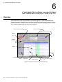
Captured Data Display and Output ........ 6-1
Isolation Pod Overview . . . . . . . . . . . . . 3-1
Mounting and Handling . . . . . . . . . . . . . 3-1
Overview . . . . . . . . . . . . . . . . . . . . 6-1
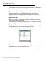
Display View Screen . . . . . . . . . . . . . . 6-2
i
Data Display Navigation . . . . . . . .
Zoom In / Zoom Out . . . . . .
Position Indicator . . . . . . . .
Pan Left / Pan Right . . . . . .
Data Display Timing: . . . . . .
Display Timing Considerations . . . .
Time Resolution - Loop Rate . .
Calibrated / Uncalibrated . . . .
Viewing Associated Run Program .
Printing . . . . . . . . . . . . . . . .
Print Complete Data File . . . .
Print a Range of Pages . . . . .
Print a Selected Page . . . . . .
Print a Selected Range of Data .
Exporting Data to a CSV File Format .
.
.
.
.
.
.
.
.
.
.
.
.
.
.
.
.
.
.
.
.
.
.
.
.
.
.
.
.
.
.
.
.
.
.
.
.
.
.
.
.
.
.
.
.
.
.
.
.
.
.
.
.
.
.
.
.
.
.
.
.
. 6-3
. 6-4
. 6-4
. 6-4
. 6-4
. 6-5
. 6-5
. 6-5
. 6-6
. 6-6
. 6-6
. 6-6
. 6-6
. 6-7
. 6-7
Isolation Pod: . . . . . . . . . . . . . . . . 8-4
Input Voltage Range: . . . . . . . . . . . 8-4
Inter-channel Isolation: . . . . . . . . . . 8-4
Input Impedance: . . . . . . . . . . . . . 8-4
Dimensions: . . . . . . . . . . . . . . . 8-4
Weight: . . . . . . . . . . . . . . . . . . 8-4
Appendix C: Isolation Pod Circuit Design. . . . 8-5
Appendix D: Alarm Output Detail . . . . . . . . 8-7
Output Port pin and function listing follows: 87
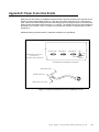
Appendix E: Power Connection Details. . . . . 8-9
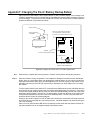
Appendix F: Changing The Clock / Memory Backup
Battery. . . . . . . . . . . . . . . . . . . . 8-11
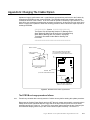
Appendix G: Changing The Crakker Eprom . 8-13
The EPROM exchange procedure follows:.813
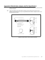
Appendix H: RS-232 Cable, Adapter, And Port
Specifications . . . . . . . . . . . . . . . . 8-15
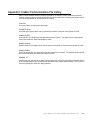
Appendix I: Crakker Communications File Listing 817
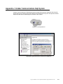
Appendix J: Crakker Communications Help System
8-19
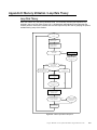
Appendix K: Memory Utilization / Loop Rate Theory
8-21
Loop Rate Theory . . . . . . . . . . . . . 8-21
Memory Utilization . . . . . . . . . . . . . 8-23
Memory Data Storage Concept . . . . 8-23
Memory Consumption . . . . . . . . . 8-23
Recording Window . . . . . . . . . . . 8-23
Further Explanation And Examples . . . . 8-23
Memory Roll-over Calculations . . . . . 8-23
Case 1: . . . . . . . . . . . . . . . . . 8-24
Case 2: . . . . . . . . . . . . . . . . . 8-24
Case 3: . . . . . . . . . . . . . . . . . 8-25
Appendix L: Crakker Accessories. . . . . . . 8-27
Ck-Case Crakker Carrying Case . . . 8-27
RPS-1 Rechargable Power Supply . . 8-27
Miscellaneous . . . . . . . . . . . . . 8-27
Appendix M: Relay Logic `first-out' Detection With
The Crakker . . . . . . . . . . . . . . . . . 8-29
Utilizing The Crakker .............................. 7-1
Overview . . . . . . . . . . . . .
Assess The Problem . . . . . . .
Minimize The Variables . . . .
Determine A Trigger Condition .
Develop The Run Program . . . .
Uploading The Run Program. .
Isolation Pod Setup . . . . . . . .
Alarm Output Connection . . .
Enable Crakker Recording . . .
Collected Data Download . . .
Data Display and Analysis. . . . .
.
.
.
.
.
.
.
.
.
.
.
.
.
.
.
.
.
.
.
.
.
.
.
.
.
.
.
.
.
.
.
.
.
.
.
.
.
.
.
.
.
.
.
.
.
.
.
.
.
.
.
.
.
.
.
.
.
.
.
.
.
.
.
.
.
.
. 7-1
. 7-1
. 7-1
. 7-1
. 7-2
. 7-3
. 7-3
. 7-4
. 7-4
. 7-5
. 7-5
Appendices .............................................. 8-1
Appendix A: Operational And Error Messages . 8-1
Crakker Communications for Windows Errors: 81
Serial Communication Problems . . . . . 8-1
Upload Failed; . . . . . . . . . . . . . . 8-2
Crakker System Base Errors: . . . . . . . . 8-2
Appendix B: Crakker Technical Specifications . 8-3
System Base . . . . . . . . . . . . . . . . . 8-3
Main Power Requirements: . . . . . . . . 8-3
Memory And Clock Backup Power: . . . . 8-3
Memory, Data Storage: . . . . . . . . . . 8-3
Input Acquisition Window:. . . . . . . . . 8-3
Display: . . . . . . . . . . . . . . . . . . 8-3
Operating Temperature Range: . . . . . . 8-3
Shipping Temperature: . . . . . . . . . . 8-3
Relative Humidity, Operating And Storage: 83
Shock And Vibration: . . . . . . . . . . . 8-3
Dimensions: . . . . . . . . . . . . . . . . 8-4
ii
Copyright
Using The CrakkerTM (Copyright 1992 - 2002)
CrakkerTM, Crakker CommunicationsTM, Isol-podTM 1992 are Registered Trademarks of Logic
Beach Inc.
Crakker Communications for WindowsTM Software (Copyright 2002)
Logic Beach Incorporated,
La Mesa, California - All Rights Reserved
The hardware, software, and operating instruction format in this manual are proprietary to Logic
Beach Incorporated, La Mesa, CA, USA. Any use, reproduction, or dissemination of this
information without express written permission from Logic Beach Inc. is prohibited.
This document is based on information available at the time of its publication. While efforts have
been made to render accuracy to its content, the information contained herein does not purport to
cover all details or variations in hardware or software, nor to provide for every possible
contingency in connection with installation, operation and maintenance. Features may be
described which are not present in all hardware and software systems.
Logic Beach policy is one of continuous improvement. The information in this document is
subject to change without notice and should not be construed as a commitment by Logic Beach.
Logic Beach assumes no obligation of notice to holders of this document with respect to changes
subsequently made.
Logic Beach makes no representation or warranty, expressed, implied, or statutory with respect
to and assumes no responsibility for the accuracy, completeness, sufficiency, or usefulness of the
information contained herein.
Original Issue: June, 1992
Revision:
Oct., 1993; Feb. 2, 1994; March 25, 2002
Logic Beach Incorporated
8363-6F Center Drive
La Mesa, CA 91942
(619) 698-3300
www.crakker.com and www.logicbeach.com
Logic Beach Incorporated www.logicbeach.com
iii
Warranty, Copyright, Receiving
Warranty Policy
Philosophy:
We at Logic Beach Incorporated continually strive to provide the best quality product available on
the market today. We realize that equipment that does not perform properly for whatever reason
can be costly, both financially as well as through inconvenience and mental anguish. For this
reason we pride ourselves on producing a quality, easy to use product as well as providing
cheerful, competent customer support through our Field Sales Representatives and our in-house
factory staff.
We always welcome your input...on ALL subjects...staff performance, literature, pricing, customer
support, product enhancements, and any other comments, complaints, or compliments that you
feel would help make Logic Beach an even BETTER company!
Warranty:
Logic Beach Incorporated will repair or replace, free of charge, all parts of said products which
are returned for inspection to its factory within one year from the date of shipment from Logic
Beach. This is provided such an inspection discloses to the satisfaction of Logic Beach that the
products are defective in material or workmanship. Equipment returned to Logic Beach for repair
must be shipped freight prepaid.
Repairs necessitated by misuse, abuse, negligence, accident or alteration of the equipment are
not covered by this warranty. No other warranties are expressed or implied, specifically those of
merchantability or fitness for specific purpose. Logic Beach is not liable for indirect or
consequential damages.
Before returning any equipment to Logic Beach, please contact us via phone to review the
problem. If you should call, please have the following information available:
* Product Model
* Serial Number of the Unit
* Problem or Reason for Returning Goods
* Contact Name and Telephone Number
Non-warranty repairs require a Customer Purchase Order, against which repair charges may be
invoiced.
The alteration or repair of this equipment except by Logic Beach personnel or Logic Beach
authorized repair facilities will void the warranty. Logic Beach is not liable for incidental or
consequential damage. If any questions arise concerning the warranty, contact Logic Beach
before taking any action.
Call Logic Beach at 619-698-3300 when information, assistance or authorization are required.
iv Using the Crakker Logic / Timing Analyzer
Receiving Inspection / Reshipment
Delivery
Upon delivery, inspect all shipping containers for signs of damage. Note any shipping damage to
the carrier before accepting the container.
We suggest retaining the original shipping container for use if it should become necessary to
reship or return the product.
A visual inspection should be made when removing the instrument from the shipping container. A
claim for any concealed damage should be placed with the carrier immediately. Retain all
shipping materials for inspection.
Inspection
Before applying power, a thorough inspection of the unit is required. Visually examine the
Crakker and Isolation Pods for:
* Cracks or abrasions
* Mechanical package damage
* Broken or damaged display buttons, etc. on Control Panels
* Damage to Pods or leads
Notify Logic Beach Customer Service Department immediately if any evidence of damage is
noted. Do Not Apply Power To A Unit That Has Visible Damage.
Reshipment
If it becomes necessary to reship the Crakker, it should be packaged in the original container
following these procedures:
1 Remove external leads and power supplies.
2 Place unit in original shipping containers with suitable packaging material for shipment or...
3 Pack according to good commercial practices using a Minimum of 4" of resilient padding
around unit if original containers are not available.
Logic Beach Incorporated www.logicbeach.com
v
Warranty, Copyright, Receiving
Notes.....
vi Using the Crakker Logic / Timing Analyzer
1
INTRODUCTION
Manual Overview
This Users manual provides information relative to the use of the Crakker (TM) Logic and Timing
Analyzer manufactured by Logic Beach Incorporated, La Mesa, CA. The manual is organized into a
progression of sections to acquaint the user with the set-up, operation, and maintenance of the
Crakker.
A section of this manual is dedicated to explaining each of the three main components that make up a
Crakker System:
1 CK-2; Crakker System Base (the main instrument with display)
2 IP-2 Signal Isolation and Conditioning Pod
3 Crakker Communications for Windows Software (CCW)
It is Highly Recommended that the User's manual be read in its entirety before using the Crakker in a
real application. The last section of the manual consists of the Appendices which give detailed
specifications and information for advanced applications and general reference.
Crakker System; the ‘Big Picture’
The Crakker Logic and Timing Analyzing System is a versatile test instrument used for
troubleshooting and performance analysis of control systems. The Crakker was originally developed
for use in troubleshooting Programmable Controller Systems (PLC's), relay logic controls and other
ON/OFF type industrial control systems. Since its conception, its applications have expanded to a
multitude of monitoring and troubleshooting applications beyond this original target.
The Crakker is used to monitor up to 16 different signals from a field control system. When a User
specified combination or transition of these signals (called a Trigger) occurs, the Crakker traps into
memory all of the transitions of these 16 inputs for a period of time prior to the Trigger as well as for a
period of time after the Trigger. The Crakker may be benignly monitoring these signals for
milliseconds or months waiting for the specific Trigger prior to trapping the data.
In a typical application, the Crakker could be left on site to monitor a number of On/Off signals (e.g.
from a PLC I/O rack) waiting for a particular combination of signal states that meet a User specified
Trigger condition. This Trigger condition typically would be an event that is indicative of an erroneous
or fault condition (e.g. valve 1, valve 2, and pump P1 should never be on at the same time).
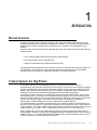
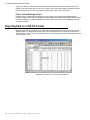
After a Trigger has occurred, the trapped data (recorded into memory within the Crakker) is then
downloaded to a Personal Computer (PC) and displayed using the supplied Crakker Communications
software (Figure 1.1). The data display graphically displays the relative and absolute timing of all 16
channels of data to time resolutions as fine as 165uS.
Logic Beach Incorporated www.logicbeach.com
1-1
1. Introduction
Figure 1.1 Resulting I/O Transition Timing Display from within CCW software
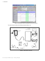
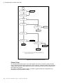
The Crakker System consists of the following components [Figure 1.2]:
HANGER
(INCLUDED WITH BOXES
NOT HAVING MOUNTING TABS)
1
5
2
6
3
7
ISOLATION
POD
SERIAL PORT
STATUS
4
8
IP-2
ISOLATION
POD
MONITORINPUTS
ENABLE RECORDING
TRIGGERED / RECORDING
STOP
RECORDING
RESET
/CLEAR
ALARM 1
ALARM 2
CRAKKER
LOGIC/TIMING ANALYZER
ALARM 1
O
RUN F
F
TEST
OFF
ALARM 2
ISOLATION
ISOLATION
POD - A
POD - B
PORT
PORT
OUTPUT/ALARM
PORT
ON
SYSTEM
POWER
CRAKKER SYSTEM BASE
CRAKKER COMM
SOFTWARE
OUTPUT CABLE
RS-232 CABLE
POWER SUPPLY
RJ-12 TO DB-9/25
ADAPTER
Figure 1.2 Crakker System Components
1-2
Using the Crakker Logic / Timing Analyzer
Isolation Pod (IP-2)
The IP-2, Isolation Pods provide the interface between the actual field control signals (up to 8 signals
per Pod) and the Crakker System Base. Utilization of the POD allows for direct connection to various
signal levels within the control system to be monitored through the supplied Insulation Displacement
Quick Connect lead pairs.
Additionally, the Pod provides for high-voltage isolation between channels and the System Base.
A multi-conductor cable connects the isolated signals from the Pod to the System Base. Up to two
Pods resulting in a total of 16 channels can be connected to the Crakker System Base.
Crakker System Base
The Crakker System Base contains additional signal conditioning circuitry, the microprocessor,
memory, clock, and supporting circuitry.
Before deploying the Crakker in the field (factory floor, etc.) a Run Program is developed then
uploaded into the Crakker’s memory which defines its operation. This Run Program is developed by
the User using the provided Crakker Communications software, then sent to the Crakker via a serial
link.
Contained within this Run Program are a number of operational parameters including the Trigger and
Alarm words as well as the User programmed Voltage Thresholds to be used by the Pod Channels for
determination of High and Low states. In use, the Crakker is constantly reading the status of the
inputs from the Pods, writing them to memory, and comparing them to the pre-programmed Trigger
word. When a match occurs, the remaining memory is filled and the Crakker stops. The User can
specify in the Run Program how the available data memory is utilized (e.g. 25% before Trigger, 75%
after).
The collected data is then downloaded from Crakker memory to the PC via a serial link using the
Crakker Communications software.
Crakker Communications for Windows Software
The Crakker Communications for Windows (CCW) program runs on a standard Personal Computer
running Windows 98, 2000 or XP and allows the User to communicate with the Crakker via a serial
link (RS-232), develop and upload Run Programs to the Crakker, and download and graphically
analyze data trapped by the Crakker.
CCW is a very powerful, yet friendly software package with easy to follow organizational flow and
menus...and understandable HELP screens with the press of a key.
Additional Components
In addition to the major components listed above, a Serial Cable, an RJ-12 to DB-25/9 adapter, a
120/240 to 12VDC power supply, and an Alarm Output Pigtail are included with the system.
Logic Beach Incorporated www.logicbeach.com
1-3
1. Introduction
Sequence of Steps to Utilize the Crakker
A typical data collection session utilizing the Crakker consists of the following sequence of steps.
This sequence of steps should be referred to during the reading of the manual to assist in clarifying
the use of the Crakker.
1 Using the CCW program, develop the Run Program for the Crakker including Trigger conditions,
Memory allocation, Alarm Triggers, Pod Signal Logic Thresholds, etc.
2 Upload the Run Program to the Crakker via the serial link. The Crakker will then adopt the
operational personality contained within the Run Program.
3 Connect the Pod signal leads to the nodes to be monitored.
4 Connect the Crakker and the Pod(s) together and press MONITOR to observe the current input
state on all active channels.
5 Connect the Alarm outputs to the Crakker (optional)
6 Enable Recording within the Crakker and wait for the Trigger to occur.
7 After the TRIGGER has occurred, connect the Crakker to the PC (running CCW) and download
the trapped data from the Crakker memory to the PC.
8 Display the data on the PC screen, analyze, print and/or output it to spreadsheet format.
Applications
Portable, enclosed, low power operation allows the Crakker to trap data in areas too punishing for
other forms of instrumentation such as strip chart recorders, plotters, storage scopes etc.
Additionally, the Crakker can be set up, connected directly to various control I/O nodes, and the data
retrieved and analyzed...all without interrupting the existing control process or reprogramming the
PLC!
Just a few uses for the Crakker...
• Trapping intermittent problems due to sticky switches, loose connections, over or under
temperature, or faulty logic.
• Testing control loop speed for time critical applications.
• Characterizing response of control systems utilizing mechanical components.
• `First Out' analysis of control logic..."who-dunnit?"
• Quantifying cycling of equipment or multiple events over time.
• Testing new code involving high speed control logic.
• Detecting suspected low-voltage conditions on control I/O nodes, Power Supplies, etc.
1-4
Using the Crakker Logic / Timing Analyzer
Features
A summary of major features incorporated into every Crakker system follows. Each feature is
addressed in further detail in later chapters.
• Extremely simple set-up and use
• Portable, self-contained, ready for stand-alone on-site use
• Eight or sixteen channel recording capability
• Direct connection (isolated) to signals ranging from TTL to 240 VAC
• 32 User Programmable Signal Logic Voltage Thresholds
• Input latching Loop Rates of 165uS (8 channels)
• Two programmable alarms (relay contact output)
• State, transition, time based, or `any change' Trigger conditions for Data Recording
• State and/or transition based Trigger conditions for Alarm output
• Provided Crakker Communication software with powerful zooming, timing measurement, and
output capabilities.
• Independent battery back-up for memory retention
• Powered by low current, low voltage AC, DC or external battery pack
• Battery backed-up Real Time Clock with 24 Hr. Time and Date
Logic Beach Incorporated www.logicbeach.com
1-5
1. Introduction
Notes...
1-6
Using the Crakker Logic / Timing Analyzer
2
C RAKKER S YSTEM B ASE
System Base Overview
The Crakker System Base contains the controlling microprocessor, memory for storing collected data
(and the Run Program), a Real Time Clock, interface circuitry to the Isolation Pod(s), and other
supporting circuitry.
This Chapter details the User interface (Liquid Crystal Display, front panel switches and buttons),
connection to the Isolation Pods and alarms, and deployment of the unit.
Mounting and Handling
The Crakker is housed in a general application plastic case that can be deployed in fairly dusty areas
protected from direct water spray. Care should be taken to prevent heavy contamination of the
connectors for the Pods and Alarms.
The Crakker can be semi-permanently mounted using the provided aluminum hanger [see
Components in Chapter 1]. The two provided screws are used to fasten the hanger to the back of the
Crakker case (two blind holes near the top). The Crakker/hanger assembly can then be fastened to
any other surface using the holes in the hanger.
************************ Caution ************************
The Crakker is not designed for direct immersion. Mount
upright for best protection.
***************************************************************
Crakker System Power
Main Power
The Crakker can be powered from any number of low voltage (8-16VDC/10-16VAC) sources through
the External Power Jack [Figure 2.1].
Logic Beach Incorporated www.logicbeach.com
2-1
2. Crakker System Base
CK-XF:
The CK-XF [see Components in Chapter 1] plug-in power pack (provided with the Crakker) has been
designed for use in providing external power to the Crakker and is equipped with a mating connector
plug.
Alternate Power Sources
Alternatively, the Crakker can be powered from any clean voltage source that is capable of supplying
150 mA and is regulated within the voltage ranges of 8-16VDC/10-16VAC. The Crakker power supply
is equipped with a full wave bridge hence polarity is not critical in the connection of DC supplies to the
Crakker External Power Jack. Refer to Appendix E for a detailed pin-out of the External Power
Connector. Additional mating connectors (with pigtail) are available from Logic Beach.
RPS-1:
For remote site applications, or applications where 120Vac is not readily available, the Crakker can be
powered from the Logic Beach Inc. Portable Power Supply (model RPS-1). The RPS-1 will provide
sufficient power to run the Crakker (in the Recording Enabled mode) for approximately 24 hours
before recharging is required.
Memory and RTC Power
The data memory (SRAM) and the Real Time Clock integral to the System Base are powered by a 3
volt lithium cell when the Crakker main power switch is OFF. This insures that the time and date and
data in memory is maintained during times when power is not connected to the Crakker.
Low-Voltage Indication
When the lithium cell voltage drops below approximately 2.6Vdc, a sensing circuit in the Crakker
detects this and displays a Low Voltage indication on the Crakker display during Status, upon
Power-Up, and after a System Reset.
Lithium Cell Replacement
If the above-mentioned Low Voltage message is seen, transfer any collected data in Crakker
memory to a PC and replace the lithium cell (or risk the loss of data in memory). Refer to
“Appendix F: Changing The Clock / Memory Backup Battery” on page 8-11 for details on changing
the lithium cell.
Power Failure During Recording
In the event that a power failure should occur while the Crakker is in the Record Enabled mode, the
Crakker will progress through a very high speed shut-down routine and save the data currently in
memory.
When power is reapplied to the Crakker after a power failure has occurred, the LCD will display a
message indicating when the power failure occurred and that data is present in memory. Data can be
transferred to the PC and displayed as normal.
2-2
Using the Crakker Logic / Timing Analyzer
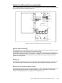
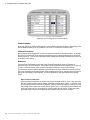
Crakker Front Panel and Connection Details
All of the System Base controls and the Liquid Crystal Display (LCD) are located on the System Base
front panel and include the following [Figure 2.1]:
4
SERIAL PORT
3
5
STATUS
6
MONITORINPUTS
11
ENABLE RECORDING
7
TRIGGERED / RECORDING
STOP
RECORDING
RESET
/CLEAR
ALARM 1
12
8
ALARM 2
9
CRAKKER
LOGIC/TIMING ANALYZER
2
10
ALARM 1
O
RUN F
F
TEST
ALARM 2
OFF
ISOLATION
ISOLATION
POD - A
POD - B
PORT
PORT
OUTPUT/ALARM
PORT
13
ON
SYSTEM
POWER
14
15
1
Figure 2.1 Crakker System Base Front Panel and Connections
System Power Switch (2)
Turns the power to the Crakker ON and OFF. Power must be turned OFF when replacing the Lithium
Cell, EPROM, or any time the Crakker is removed from its case.
The system power does not affect data in memory or the Real Time Clock time/date as both have a
lithium battery backup power source (“Appendix F: Changing The Clock / Memory Backup Battery” on
page 8-11). This memory back-up battery will protect stored data for approximately one year at
normal room temperatures.
Display (3)
An extended temperature range, 2-line by 16 character, liquid crystal display (LCD) is provided. Date,
time, status and other informational set-up and operational messages are displayed on the LCD.
RS-232 Serial Communications Port (4)
A female 6/6 RJ-12 modular phone type jack is provided. A three wire RS-232 connection scheme is
utilized with additional connections for future expansion. Refer to “Appendix H: RS-232 Cable,
Adapter, And Port Specifications” on page 8-15 for a detailed pin-out.
Logic Beach Incorporated www.logicbeach.com
2-3
2. Crakker System Base
This port is connected to the RS-232 serial port on the PC via the supplied serial cable and adapter
[see Components in Chapter 1]. A standard four conductor telephone `base' type (not `headset')
cable can be utilized for longer RS-232 distances. These cables are available from Logic Beach or at
most stores that sell telephones and supplies.
At lower Baud Rates (e.g. 1200 Baud) in low electrical noise environments, RS-232 communication in
excess of 100' has been successfully achieved.
Push Buttons
Status / Time (5)
Depressing this button will result in a sequence of displays on the LCD that indicate current Status
of the Crakker. Displays will vary depending on whether or not collected data is retained in
memory. The Status button will only respond when the Crakker is in the IDLE mode, i.e.
Recording is NOT Enabled.
The Status display sequence with data in memory is:
DATA RECORDED <FINISHED> @ TIME ON DATE: indicating that collected data is currently
retained in memory waiting for transfer to the PC or to be cleared. The Time and Date indicate
when the recording session ended.
Crakker Time And Date: currently maintained within the Crakker Real Time Clock (RTC). If the
Time and Date are incorrect, they can be set through the CLOCK SET feature in the Crakker
Communications program (see Chapter 4). If the time and date become incorrect shortly after
setting, this could indicate a discharged memory/RTC battery backup lithium cell (see“Lithium Cell
Replacement” on page 2-2).
CURRENT Run Program LOADED: the name of the Run Program currently loaded into memory
and the three line Program Description specified during the development of the Run Program is
displayed.
If no Run Program is in memory, "NO Run Program LOADED" is displayed.
Press Status To Display Ch Names: this message is displayed for approximately three seconds.
While the message is displayed, if the Status button is depressed again, the Crakker proceeds to
display the first Channel Description entered by the User during the development of the Run
Program.
Pressing the Status button repetitively steps the display through each of the Channel Descriptions.
Step through all of the channels and the Crakker returns to the READY display mode.
Note
This Channel Description feature can be extremely handy in the field when hooking up the
Isolation Pod leads, serving as a sequential list of connections to be made.
If no data is in memory, the Status display also indicates that the Crakker is currently in the
"SYSTEM IDLE" mode before it sequences to the current Crakker Time and Date and continues
into the above sequence.
Monitor (6)
Pressing the Monitor button while the Crakker is IDLE (i.e. Recording is not Enabled) results in a
continuously updating display of the input channels states. A `0' or a `1' will be displayed for all 16
channels (even if only one Pod is connected). A `1' indicates a voltage presence on that input in
excess of the turn-on threshold (i.e. the input is ON).
2-4
Using the Crakker Logic / Timing Analyzer
A rapidly fluttering 0/1 display may indicate an AC input that requires a Debounce setting (See
Debounce setting in Chapter 5).
The Monitor feature can be used during the connection of the Crakker and Pods to a system to
insure that good electrical contact is made and that a channel is functioning as anticipated.
Press the Stop Recording button to exit from the Monitor display.
Enable Recording (7)
Note
Pressing the Enable button initiates the continuous monitoring of the Input signals from the Pods
and comparison to the Record and Alarm Triggers defined in the currently loaded Run Program.
After pressing the Enable button, the name of the currently loaded Run Program and its three line
description are displayed. The LCD then changes to `RECORD ENABLED <WAITING>' while it
continually loops testing for a Trigger condition match.
If data is still in memory from a prior RECORDING session, RECORDING will not start. The
following sequence will be displayed on the LCD:
DATA IN MEMORY
TRANSFER AND CLEAR MEMORY
RECORDING NOT ENABLED
In order to Enable a Recording session, it is necessary to transfer the data in memory to the PC (if the
data is to be saved), clear memory (see following for Clear Memory sequence), and then press the
Enable Recording button.
Stop Recording (8)
If the Crakker is in the Monitor mode, the Stop button exits that mode and returns the Crakker to
IDLE mode and the display to `READY'.
If the Crakker is in the RECORD ENABLED mode, pressing the Stop button immediately cancels
the session and the display changes from `RECORD ENABLED <WAITING>' to `RECORD
ENABLED <FINISHED>'.
Data recorded in memory between the ENABLE of RECORDING and the STOP of RECORDING
will be retained in memory and must be transferred to the PC or CLEARED before another
RECORD session can be ENABLED.
Reset / Clear Memory (9)
Used in conjunction with the Stop Recording button to perform system Resets and if desired,
Clear data memory. This button must be pressed simultaneously with the Stop Recording button
for response (to insure against accidental clearing of memory).
If data is present in memory from a prior recording session, when the two buttons are pressed
simultaneously, the following message sequence will display:
CRAKKER VX.X c 1992
RESET AGAIN TO CLEAR MEMORY
At this point, a Crakker system RESET has occurred without affecting data stored in memory. If
no further action is taken, the display will return to
Logic Beach Incorporated www.logicbeach.com
2-5
2. Crakker System Base
DATA RECORDED <FINISHED>
or
DATA IN MEMORY SEND AND CLEAR
If erasure of stored data in Crakker memory is desired, the two buttons must be depressed a
second time while the `RESET AGAIN TO CLEAR MEMORY' message is still displayed. A
message will then prompt the User `ARE YOU SURE? RESET IF YES'. If memory clear is
desired, perform a third two button RESET.
This action will initiate a memory erasure sequence with a corresponding `CLEARED MEMORY'
display.
*************************** Caution ************************
IF DATA STORED IN MEMORY IS TO BE RETAINED, THE
DATA MUST BE TRANSFERRED TO THE PC BEFORE
CLEARING MEMORY.
DATA CLEARED FROM MEMORY CANNOT BE
RESTORED.
***************************************************************
Note
At the completion of the memory clearing process, the LCD displays READY. Total available memory
can be verified with the Status/Time Button.
If a Power Failure occurs during a RECORDING session, appropriate messages will be displayed on
the LCD indicating the occurrence of the failure and when it happened.
Alarm Control Switches (10)
Two Alarm relay (isolated N/O contact closure) outputs are provided on the Crakker. These Alarm
outputs are energized if the Crakker input signals from the Pod(s) match the programmed Alarm
Triggers contained in the Run Program currently running in the Crakker.
The ALARM 1 and ALARM 2, 3-position switches on the front panel of the Crakker are provided for
manual override of the ALARM outputs. Description of operation in the three positions follow:
OFF: in the center position, the Alarm Output relays are disabled and can not be turned ON
by the Crakker software.
TEST: when the switch is toggled to the right, the Alarm Relay is forced into an ON state and
the relay contacts are closed. This is a `momentary' position and when the switch is
released, it returns to the OFF position.
RUN: in the left position, the Alarm Relay is under the control of the Crakker microprocessor.
The relays will be switched ON and OFF per the logic contained in the Run Program.
Wiring details for the ALARM outputs are contained in “Appendix D: Alarm Output Detail” on page 8-7.
Note:
2-6
When the Crakker main power is switched ON, and the ALARM switches are in the RUN position, the
output relays may cycle ON for a few hundred milliseconds. For this reason, when cycling the power,
it is recommended that the Alarm switches be left in the OFF position.
Using the Crakker Logic / Timing Analyzer
Triggered / Recording Light (11)
When the Crakker is in the RECORD ENABLED mode and a Record Trigger condition is met, the
Crakker turns on this light and continues recording data to fill its memory.
When memory is filled, the light turns OFF and the LCD displays DATA RECORDED <FINISHED>,
indicating that a successful Recording session has been implemented.
Note
If the TRIGGERED/RECORDING light is ON and the LCD displays RECORD ENABLED <WAITING>
the Crakker is continuing to write Post-Trigger data to memory. If this Post-Trigger data is not
needed, the front panel Stop button may be pressed and the session will be ended. Data can then be
transferred to the PC for display.
Alarm Status Lights (12)
When the Alarm Output Relays are ON (contacts closed) the corresponding Alarm Status Lights will
be lit.
Isolation Pod Connections (13 and 14)
One or two, 8 input Isolation Pods can be directly connected to the Crakker System Base via the
Isolation Pod Ports[Figure 2.1] located on the bottom of the Crakker.
In connecting the Pod(s), visually inspect the both the male and female connectors before plugging
them together to insure that no pins are bent or dirt is on the contacts. Tighten the retaining screws
securely to insure good electrical connection.
***************************** CAUTION *********************
Connect ONLY Logic Beach Isolation Pod cables to the
these ports. These ports are NOT for High Voltage nor
Serial Communication.
***************************************************************
Output / Alarm Port Connections (15)
A single Male DB-9 connector port is provided for connection between the two internal Alarm Relays
and the outside world. Connection to these this port can be made using the provided mating
connector pigtail or any mating DB-9F equipped cable.
A pin-out for the connector is provided in “Appendix D: Alarm Output Detail” on page 8-7.
************************ CAUTION ************************
Connect ONLY low voltage (i.e. 32 Vac/Vdc maximum) low
current (500 mA maximum) loads to these Alarm Outputs.
This port is not for high voltage nor serial communications
**************************************************************
Logic Beach Incorporated www.logicbeach.com
2-7
2. Crakker System Base
Notes....
2-8
Using the Crakker Logic / Timing Analyzer
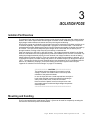
3
ISOLATION PODS
Isolation Pod Overview
The Isolation Pods used in the Crakker System provide signal conditioning and high-voltage isolation
between the Crakker System Base and the signal connection nodes. Additionally, the Pod provides
high-voltage isolation between channels as well as initial signal conditioning.
One Pod can accept up to 8 signal inputs and two Pods can be used with one Crakker providing up to
16 channel capability. Each Pod is supplied with eight pairs of connection leads. The leads are
equipped with Insulation Displacement Quick-Connect Clips that are capable of clipping onto leads up
to 12 AWG. The clips have a sharpened spike integral to the J-hook that can be used to pierce
through insulation, making a fast convenient connection to insulated wire.
Pods can accept up to 280 VAC or 400 VDC directly. The voltage thresholds utilized for the Signal
HIGH or LOW decision are User programmed (via the CCW software) from a choice of 32 values. By
setting the voltage thresholds properly for each channel, low voltage conditions as well as floating
voltage effects of leaking currents in Triac type outputs are readily accommodated / detected. (i.e. in
Triac switched outputs, a sizable voltage may exist on an unloaded output even though the output is
`OFF'). The sensing circuitry for each channel has an input impedance for DC of 220Kohms and for
60hz AC of 120Kohms, resulting in a minimum loading on the control system under test.(see
“Appendix C: Isolation Pod Circuit Design” on page 8-5 for details).
********************** CAUTION ***************************
The isolation pods are designed for connection to high
voltage, however care must be taken in the set-up and
utilization of the pod and its leads.
In use, the clips will have a small exposed bare area (the Jhook at the end) that must be prevented from shorting to
other points, leads, wires, as well as to humans.
Never remove the plastic cover from the pod as no user
serviceable parts are inside and high voltage components
will be exposed.
***************************************************************
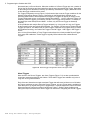
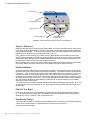
Mounting and Handling
The Pod is supplied with a metal hanger [Figure 3.1] that can be used for temporarily mounting the
Pod near the connection points to be monitored.
Logic Beach Incorporated www.logicbeach.com
3-1
3. ISOLATION PODS
The Pod enclosure is sealed from dirt and dust however the Pod should not be used in wet areas
without further protection. The Pod cover should never be removed as high voltage nodes will be
exposed and no User serviceable parts are contained within the enclosure.
The enclosure is made from plastic that can melt if exposed to high temperatures. Do not subject the
Pod to extremely high heat (60C, 140F maximum operating ambient temperature). The electronic
components within the Pod are designed for rugged normal use, however if the Pod enclosure is
physically damaged in any way or if the unit experiences high impact (e.g. a hard drop onto a
concrete floor), the unit should be returned for test and inspection by qualified Logic Beach staff.
HANGER
1
5
2
6
3
7
SIGNAL INPUT
JACKS (2/CHANNEL)
8
IP-2
ISOLATION
POD
4
QUICK-CONNECT
LEADS (2/CHANNEL)
POD TO CRAKKER
CABLE/PLUG
ISOLATION
POD
Figure 3.1 An Isolation Pod
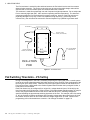
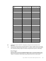
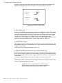
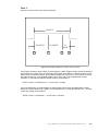
Pod Switching Thresholds... Vth Setting
During a recording session, the Pod is constantly comparing the input signal (from a control system
node) to an internal voltage threshold (Vth) which has been set by the User in the development of the
Run Program (from within CCW). When the monitored input signal exceeds the Vth threshold, the
Pod communicates a HIGH state to the Crakker System Base and when the input signal is lower, a
LOW state is communicated.
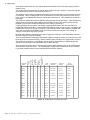
Each Pod channel can be configured for a unique Vth, voltage threshold (one of 32 levels) by the
User from within the CCW program. Refer to Figure 3.2 for approximate switching points (in volts) for
each of the programmable Vth levels. Both OFF to ON and ON to OFF switching voltages are
specified indicating the approximate switching hysteresis of the Pod. For example, with a Vth setting
of `90', the Crakker will detect an ON state with increasing voltage when the signal rises to 90 Volts,
the Crakker will then detect an OFF state when the voltage drops below 78 Volts. Details on the
programming of this Vth threshold are covered in “Vth Voltage Threshold” on page 5-8.
3-2
Using the Crakker Logic / Timing Analyzer
Programmed Vth Level
(Vdc)
Approximate
Approximate
OFF to On Voltage (Vdc) ON to OFF Voltage (Vdc)
2.0
2.0
1.3
2.5
2.5
1.7
3.0
3.0
2.2
4.0
4.0
3.0
5.0
5.0
4.0
6.0
6.1
4.6
8.0
8.1
6.0
10.0
10.0
6.9
15
15
10
20
19
13
25
25
19
30
30
21
40
40
31
50
50
40
60
58
48
70
70
59
80
82
70
90
90
78
100
100
87
110
112
101
120
122
111
130
130
118
140
139
127
150
150
140
160
158
147
170
169
159
180
182
174
190
190
182
200
198
190
210
212
205
Figure 3.2 Isolation Pod Voltage Threshold Switching Values (approximate)
Prior to the programming of the Vth levels, it may be prudent to check the On/Off voltage levels of the
nodes to be monitored during normal operation (using a voltmeter) to insure:
1 The voltage levels are within the maximum withstand range of the IP-2 Isolation Pod channels.
2 For future reference during the Vth programming process from within CCW.
Logic Beach Incorporated www.logicbeach.com
3-3
3. ISOLATION PODS
Special Considerations - Triacs
In many control systems, AC signals are controlled with a `solid state switch' or Triac (or SCR for DC).
These switches (unlike relays or mechanical switches) commonly have some leakage of current in
their `OFF' state that can result in minimally loaded outputs `floating' up to 40 to 50 VAC. Evidence of
this phenomenon is sometimes seen in where a pilot light on a controlled output may glow
dimly...however the output it is connected to is theoretically `OFF'. The leakage current is sufficient to
dimly illuminate the pilot light but insufficient to energize the main load.
To handle the interface to these type outputs, the Pod Vth thresholds can be set to a higher level,
thereby requiring a `solid' ON driving voltage to be sensed as a logical ON by the Isolation Pod. By
measuring the ON and OFF voltage levels during normal cycling of an electrical node a feel for the
switching levels can be achieved. Alternatively, a value substantially higher than the halfway point
may be used, for example setting the Vth to 80V for use on a 120VAC rms system. Proper Vth setting
can be verified through use of the Monitor command on the Crakker System Base (“Monitor (6)” on
page 2-4).
Connecting The Pod To Signal Nodes
Isolation
Each channel of the Pod is electrically isolated from the others and from the Crakker. Due to this
isolation feature, each channel within a single Pod can be connected to a different voltage node on
the system to be monitored. The Channel leads are NOT polarity sensitive.
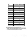
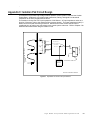
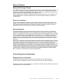
A Bit Of Theory...
Note
3-4
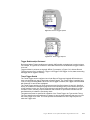
The Pod signal lead pair is connected to a voltage divider within the Pod internal circuitry (Figure 3.3).
The output of this voltage divider is a scaled down voltage representative of the Input Signal Voltage.
This scaled down voltage is then sent to signal conditioning and threshold comparison circuitry which
then sends a digital (on/off) opto-isolated signal to the Crakker System Base.
On the input voltage divider, a capacitive filter resides for spike protection. Due to this capacitance,
the effective input impedance of a channel is a function of the frequency of the input signal. In
Appendix B, effective input impedance is listed as a function of the monitored signal frequency.
The input impedance of the Pod is effectively a measure of the loading that the Pod circuitry will add
to the circuit under test. To operate, the Pod draws a minimal current from the control circuitry under
test due to this input impedance. The higher the impedance, the better (for most applications) as high
impedances draw less current. As can be seen in Appendix B, for DC signals, the input impedance is
over 220K ohms and for 60 Hz AC, the effective impedance is over 130K ohms.
Another effect of the capacitive filtering on the inputs is manifest when the signal voltage impressed
on the inputs turns off, the capacitors tend to delay turn-off of the signal to the Crakker System Base.
To optimize the speed response of the Crakker System, connections should be made in a manner
that results in the Pod inputs being driven to a High or Low state as opposed to being allowed to `float'
for the OFF condition. The delay in response will be a function of the Vth setting and the effective
impedance of the node being monitored. Connection methods to minimize this delay are discussed in
the following section.
Using the Crakker Logic / Timing Analyzer
1 KOHM
100 KOHM
0.01uF
C1
RECTIFICATION
SIGNAL CONDITIONING
COMPARISON
CONNECTION TO SIGNAL
NODES
CIRCUITRY
TO CRAKKER
20 KOHM
CKT
GND
C2
0.01uF
100 KOHM
1 KOHM
SOFTWARE
PROGRAMMABLE
VOLTAGE
THRESHOLD
(Vth)
OPTO-ISOLATOR
SINGLE CHANNEL SHOWN
Figure 3.3 Equivalent Isolation Pod Input Circuitry
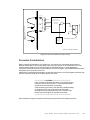
Connection Considerations
Before connecting Pod leads to any signal node, it is important to understand and assess any
potential effects that the Pod current draw may have on the system to be monitored. Due to the
relatively high impedance of the Pod channels (as explained above), for most applications,
connection of the Pod will have no effect however, for low level signals, the potential effects should be
assessed before connection of the Pod.
Additionally, by optimally determining the connection techniques to insure that signals are driven high
and low, maximum speed of the Crakker System will result.
****************** CAUTION *******************************
If any question exists about the effect of connecting the pod
leads to a critical control system, it is imperative that these
questions be resolved before proceeding.
If this cautionary procedure is not followed, possible damage
to equipment or life may result. Study each situation
carefully before proceeding and feel free to contact Logic
Beach Technical Support for assistance if desired.
**************************************************************
Some examples of typical connection techniques are discussed in the following sections.
Logic Beach Incorporated www.logicbeach.com
3-5
3. ISOLATION PODS
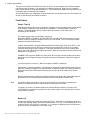
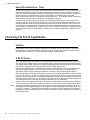
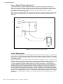
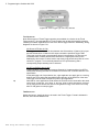
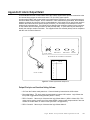
Triac or Relay PLC Output [Figure 3.4]:
The Pod leads are connected in parallel with the load. When the PLC output is energized, an
additional 1 mA (apx at 120VAC output) of current flows through the Pod detection circuitry. In the
case of Triac outputs, the small load presented by the Pod will actually help pull the output voltage
closer to 0V when the output is `off' (see discussion on Triac leakage currents in “Special
Considerations - Triacs” on page 3-4).
When the PLC output cycles OFF, the Pod inputs are effectively `shorted' through the low impedance
of the load, insuring maintenance of the speed of the Pod input circuitry (see “A Bit Of Theory...” on
page 3-4).
TRIAC
OR RELAY
OUTPUT
HOT
120VAC
LOAD
PLC
NEUTRAL
ISOLATION POD
1
5
2
6
3
7
4
8
IP-2
ISOLATION
POD
Figure 3.4 Pod Connection to Triac / Relay Outputs
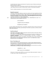
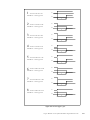
Current Sinking Inputs
PLC controls commonly use current sinking digital inputs that turn ON when they are connected to the
AC `HOT' line. A typical connection with a proximity or limit switch is shown in Figure 3.5. When the
switch closes, a current path exists between the 120VAC `HOT' terminal and the PLC Input Terminal
turning that input ON.
Figure 3.5 shows one method of connection of the Pod leads to this type of circuit. In an open switch
condition, 0V exists across the Pod leads (logic 0). When the switch closes, 120Vac is supplied to the
PLC Input Terminal (turning it ON) as well as being impressed across the Pod leads (logic 1).
For inputs operating from higher voltage supplies (e.g. 120VAC and above, as shown) this is the
preferred method of connection as the small current that flows through the Pod circuitry will not have
any effect on the PLC input circuitry as the two circuits are in parallel. The only concern with this
connection configuration might be with respect to the turn off speed of the Pod input circuitry. When
the Prox Switch is open, the Pod input circuitry is `shorted' through the circuitry contained within the
PLC, however if the PLC utilizes some very high impedance input circuitry, the Pod circuit may have
as high as 5 mS of delay before it turns off. This delay can be minimized by setting the Vth to a higher
level (e.g. for a 120VAC supply, setting the Vth at 80V rather than at 20V will speed up the system
response).
3-6
Using the Crakker Logic / Timing Analyzer
VAC
SUPPLY
HOT
PLC
PROXIMITY
SWITCH
AC INPUT
NEUTRAL
1
5
2
6
3
7
ISOLATION POD
4
8
IP-2
ISOLATION
POD
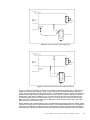
Figure 3.5 Pod Connection to a PLC Digital Input
24 VAC
SUPPLY
HOT
PLC
PROXIMITY
SWITCH
AC INPUT
NEUTRAL
1
5
2
6
3
7
4
8
ISOLATION POD
IP-2
ISOLATION
POD
Figure 3.6 Pod Connection to a PLC Input (Alternate Method)
Figure 3.6 shows an alternative connection for monitoring a similar type digital input. With this type
connection, when the Prox Switch is open, a logic HIGH will be recorded and when the switch is
closed, a logic LOW will be recorded by the Crakker. The advantage of this connection is that the Pod
inputs are driven high and low solidly, resulting in maximum speed. However, with this connection
configuration, when the Prox Switch is open, a small current can still flow around the switch to the
PLC Input Terminal via the Pod detection circuitry. For a control with very sensitive input circuitry
within the Input Terminal, this current may be sufficient to effect a High condition on the PLC input
when in fact, the Prox Switch is open.
With a 24VDC supply used (as shown), the current that will flow around the open Prox Switch (via the
Pod Input circuitry) to the PLC Input will be less than 0.1 mA (24VDC/220,000 ohms =0.1mA) which in
most cases is insufficient to switch an Input to a HIGH state...however reference should be made to
the Specification / Operating manual for the Control under test before utilizing this connection method.
Logic Beach Incorporated www.logicbeach.com
3-7
3. ISOLATION PODS
Note that the current that flows is in direct proportion to the supply voltage...for example, with a 5VDC
supply, less than 23uA of current will flow (5VDC/220,000 ohms = 22.7uA).
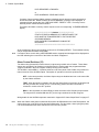
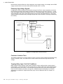
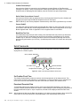
Extremely High Voltage Signals:
In applications utilizing voltage levels beyond the range of the Pod, it may be necessary to connect
the Pod leads across the load contactor actuation coil that is driven by the PLC (Figure 3.7). In this
case, the voltage is within the Input Range of the Pod. The disadvantage of this technique is that the
actual load side of the circuit is not being sensed in turn-on time critical applications (i.e. the actual
electromechanical actuation delay of the high voltage load control contactor is not being measured by
the Crakker).
HI-VOLTAGE
SOURCE
TRIAC
OR RELAY
OUTPUT
HOT
HI-VOLTAGE
MOTOR STARTER OR
CONTACTOR
(120VAC COIL)
120VAC
PLC
NEUTRAL
LOAD
ISOLATION POD
1
5
2
6
3
7
4
8
IP-2
ISOLATION
POD
Figure 3.7 Hi-Voltage Node Connection Scheme
Contactor Actuation Time:
The Crakker employed in a circuit as shown in Figure 3.8 can be used to measure the actuation delay
across a contactor. Here, two channels are used to measure the actuation signal and the load
voltage.
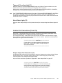
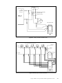
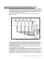
Trapping Relay Logic `first Out' Conditions:
Many industrial control systems utilize master shutdown circuits configured with a series string of
relay contacts. In the event that any of the relays open, a master control relay opens shutting down
the process/system under control. Pod connections to determine which of the series relays opens
first (`First Out' detection) are shown in Figure 9a. Additional technical information on First Out
applications is contained in “Appendix M: Relay Logic `first-out' Detection With The Crakker” on
page 8-29.
3-8
Using the Crakker Logic / Timing Analyzer
220 VAC
SOURCE
TRIAC
OR RELAY
OUTPUT
120VAC
MOTOR STARTER OR
CONTACTOR
(120VAC COIL)
PLC
NEUTRAL
LOAD
ISOLATION POD
1
5
2
6
3
7
4
8
IP-2
ISOLATION
POD
Figure 3.8 Testing Contactor Actuation Time
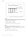
(K1 - K5 HAVE NORMALLY OPEN CONTACTS)
K1
K2
K3
K4
K5
120VAC
120VAC
NORMALLY
CLOSED
K6 CONTACTS
NEUTRAL
ALARM
1
5
2
6
3
7
4
8
NEUTRAL
IP-2
ISOLATION
POD
ISOLATION POD
Figure 3.9 Relay Logic ‘First Out’ Detection
Logic Beach Incorporated www.logicbeach.com
3-9
3. ISOLATION PODS
The concepts presented in the above examples can be extrapolated to many other logic and timing
analysis applications. Feel free to contact our technical staff for assistance in any other unique
applications.
Pod To Crakker Interconnection
Isolation Pods are connected to the Crakker System Base via the multi-conductor cable and its DB-15
type connector. If only using one Pod, connect to Port A on the Crakker to allow for the fastest scan
rates.
Tighten the connector retaining screws securely to insure a good electrical connection.
3-10
Using the Crakker Logic / Timing Analyzer
4. Crakker Communications for Windows
4
C RAKKER C OMMUNICATIONS FOR W INDOWS
Overview
The Crakker Communications for Windows (CCW) software is an integral component of the Crakker
Logic / Timing Analyzer system. CCW performs four major functions during normal use of the
Crakker:
• Serial Communications: Serial communication is fully implemented allowing the Crakker to
communicate with the Personal Computer (PC) via a provided RS-232 serial cable.
Communication is employed in programming the Crakker from the PC and in the transfer of
collected data from the Crakker memory to the PC.
• Crakker Programming: The Crakker performs its Triggered data collection and Alarming
functions per the instructions contained within a Run Program. This Run Program is developed on
the PC (using the CCW program) then transferred to the Crakker's memory where it executes.
• Display of Recorded Data: Data collected by the Crakker in a Recording session is downloaded
and saved to a file on the PC, then graphically displayed on the PC for inter-channel and absolute
timing and state analysis.
• File Export: The collected data file can be converted into a Comma Delimited File format (*.csv)
which in turn can be opened with Microsoft Excel and other spreadsheet applications.
Installation and an introduction to the Crakker Communications for Windows software is covered in
this chapter. Following chapters detail using CCW for programming the Crakker and captured data
display and data export.
PC Hardware / Software Requirements
CCW runs on WinTel compatible PC’s running Microsoft Windows 98, 2000, XP and NT.
An RS-232 serial port is required for communication with the Crakker System Base and a CDROM
drive for installation of CCW.
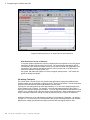
CCW Installation
CCW is provided on CDROM packaged with the Crakker System Base. To install CCW perform the
following steps:
1 Close all currently running applications
2 Insert the provided CDROM into the drive
3 Upon drive tray closure, the installation program will automatically start. In the event that the
installation does not automatically start, select the Run menu from the Start (if this does not
occur, use the Start menu to select Run then select the file Setup.exe on the CDROM drive)
4-1
Using the Crakker Logic / Timing Analyzer
4. Crakker Communications for Windows
4 Installation will automatically proceed and requests will be made for the desired installation
directory. The default installation directory (recommended) is C:\Windows\Program Files\Logic
Beach\Crakker Comm for Windows. Use the default path or specify an alternate desired drive,
path and directory and continue.
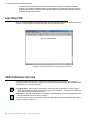
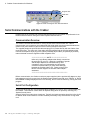
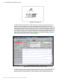
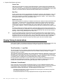
Launching CCW
Upon successful installation of the CCW program, launch CCW with the conventional Windows Start |
Programs | CCW sequence and CCW will launch with the following display:
Figure 4.1 Crakker Communications for Windows Opening Screen
CCW Architecture Overview
CCW has two main windows, the Program View window and the Data View window. Details on
developing Crakker Run Programs within the Program Window and data display from within the Data
View window are in following chapters.
1 Program View: The Program View window is used during the development of a Run Program
which is then transferred to the Crakker’s memory where it executes… performing the conditional
event data collection and alarming function.
2 Data View: The Data View window is for display of collected control system timing data after it has
been downloaded from the Crakker’s memory.
To switch between the two view windows, click on the appropriate buttons on the Button Bar or select
from the View menu (Figure 4.2).
4-2
Using the Crakker Logic / Timing Analyzer
4. Crakker Communications for Windows
Program View
Data View
Figure 4.2 Data and Program View Selection Buttons
Serial Communications with the Crakker
Programming of the Crakker and collected data downloads from the Crakker are performed via an
RS-232 serial connection linking the Crakker System Base and the PC.
Communication Overview
The Crakker communicates with the PC via an RS-232 serial communication link. Before
communication can commence, the supplied RS-232 serial cable must be connected between the
Crakker front panel Serial Port and one of the Personal Computer serial ports.
The supplied telephone style RS-232 cable and plug (RJ-12) mates directly with the Crakker front
panel Serial Port. The other end of the cable should be plugged into the supplied adapter which
converts the telephone style plug to the industry standard 25 pin DB-25 (or optionally 9 pin DB-9)
male serial data connector supplied on IBM compatible PCs.
************************** NOTE ***************************
Utilize only Logic Beach adapters that directly connect into
the serial port on your PC. Although a multitude of gender
and DB style adapters are manufactured by other
companies, many are incompatible and will prevent
successful communication (or could cause damage)
between the Crakker and the PC. Please contact Logic
Beach Technical Support for alternate cable adapter
assistance.
**************************************************************
Before communication, the Crakker must have power supplied (via the provided AC adapter or other
low-voltage source) to the power jack, the System Power switch turned ON, and a `READY' or `DATA
RECORDED' message displayed in the LCD. Similarly, the PC must be booted up, running the CCW
program.
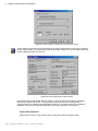
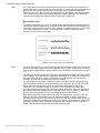
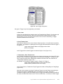
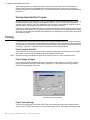
Serial Port Configuration
A serial port and baud rate must be selected after installation of CCW for use in communication with
the Crakker. This selection is done within an Options dialog which is opened by selecting File |
Options from the menu.
Select a Serial Port number then a baud rate. Typically, the baud rate setting should be left at 19.2K
for fastest serial communications in all but extremely electrically noisy environments or long cable
runs.
4-3
Using the Crakker Logic / Timing Analyzer
4. Crakker Communications for Windows
Figure 4.3 Options dialog for Default Path and Serial Comm setup
A quick test of the serial link can be performed via the Query Status button or menu choice Crakker |
Query Crakker Status. This command queries the connected Crakker for a current system status and
returns a dialog as shown in Figure 4.4.
Figure 4.4 Query Crakker Status response dialog
At the start of any communication with the Crakker, a series of short commands are exchanged
between the Crakker and the PC. If any problems exist in the serial link or configuration, a
communication error message will be displayed on the PC. In the event that an error message is
displayed, a quick check of the following points will remedy the problem in most cases.
Correct Port Specified?
Check that the correct PC port is being used. Change from within the Options dialog.
4-4
Using the Crakker Logic / Timing Analyzer
4. Crakker Communications for Windows
Crakker Powered Up?
Insure that the Crakker is powered up and is displaying a steady Ready or Data Recorded
message in its display. Serial communications cannot operate while the Crakker is in the Record
Enabled mode (if displaying Record Enabled, press the Crakker front panel Stop button).
Serial Cable Connections Correct?
Note:
Insure that the RS-232 cable is seated securely in the front panel Serial Port of the Crakker and
plugged securely through the DB-9/25 adapter into the PC serial port.
DB-9 to DB-25 (or the reverse) adapters manufactured by other than Logic Beach may not work!
Correct Cable?
If a cable other than the RS-232 cable supplied with the Crakker is used, insure that it is a four or
six conductor cable with the modular plugs installed in the same exact configuration as the Logic
Beach supplied cable. Refer to Appendix H or the supplied cable for verification.
Baud Rate Too Fast
If a substantially longer RS-232 cable is being used, the Baud Rate may need to be decreased.
For general reference, 9600 Baud rates have been successfully used between a PC and the
Crakker at up to 100 feet in relatively electrical noise free environments (although the RS-232
specs specify performance up to 50 feet). If problems persist, switch to a slower rate and repeat
the test.
Serial Commands
Following is an explanation of the serial commands and responses commonly used during the
deployment of a Crakker system.
Query Crakker Status
Set Crakker Clock
Analyze Run Program
Download Data
Upload Run Program
Figure 4.5 Serial Communications Buttons within CCW
Set Crakker Clock Tim e
The Crakker System Base includes a real-time clock that keeps track of the date and time. This
internal clock is used for time-stamping of recorded data. To set the Crakker clock to match the PC
clock click on the Set Clock button or use the menu selection Crakker | Set Crakker Clock.
Download Recorded Data
NOTE:
4-5
To download data from the Crakker memory click on the Download Data button or use the menu
selection Crakker |Download Data from Crakker. A status dialog will open showing the progression of
the serial download sequence. Upon completion, the data will be displayed within the Data View
window.
After download of data into the Data View window, if it is desired to save the data to disk, use the File
Save button or the menu selections. Downloaded data is not automatically saved to disk.
Using the Crakker Logic / Timing Analyzer
4. Crakker Communications for Windows
Upload Run Program
NOTE:
After a Run Program has been developed (or loaded from file into CCW), it can be transferred to the
Crakker memory where it executes. Clicking on the Upload Run Program button transfers the Run
Program currently open within CCW into the Crakker memory. Note that the Upload Run Program
button is only available (i.e. not grayed out) in the Program View window.
To prevent inadvertent loss of recorded data within the Crakker, it is not possible to upload a new Run
Program to the Crakker if the Crakker currently contains recorded data. An error dialog will display
stating the Crakker memory must be cleared. Download the data (if desired) then clear the Crakker
memory using the sequence of simultaneous Stop and Clear front panel button presses.
Analyze Run Program
From within the Program View window in CCW, clicking on the Analyze Run Program button results in
a overview analysis of the expected performance of the Current Run Program open in CCW (i.e. not
the Run Program in the Crakker memory). Details on the Analysis are covered in “Analysis of Run
Program Performance” on page 5-16
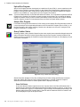
Query Crakker Status
Selecting Crakker | Query Crakker Status from the menu results in two sequential dialogs that provide
status information about the Crakker System Base and the Run Program currently loaded into the
Crakker’s memory. Pressing the Crakker front panel Status button will result in a local display of much
of this same information.
Figure 4.6 Query Crakker Status (first dialog)
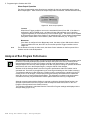
Status information displayed in the first resulting dialog includes settings specified and contained
within the Crakker Run Program. Run Program development is covered in detail in Chapter 5.
Additional information about the Crakker System Base is displayed including:
Power Fail Status
In the event that the Crakker experiences a loss of power while in the Record Enabled mode, it
performs a very fast orderly shut-down and preserves all data currently in memory. If this occurs,
either a Failed After Trigger or a Failed Before Trigger message will be displayed indicating to the
User the status at the time of power failure. Data can still be transferred from the Crakker to the
PC and displayed in spite of the power failure.
4-6
Using the Crakker Logic / Timing Analyzer
4. Crakker Communications for Windows
Battery Status
If the lithium battery used to power the Crakker internal Real Time Clock and backup internal
memory is low on energy, a Low Battery message will be displayed. If this message is seen,
desired data in memory should be transferred from the Crakker to the PC and the lithium cell
should be replaced (see “Appendix F: Changing The Clock / Memory Backup Battery” on
page 8-11).
Data Status
An indication if data is currently maintained in memory or if it has been cleared since the last
Recording session.
Recording Stopped
The time and date when the Crakker stopped writing data to memory during the last Recording
session.
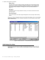
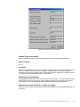
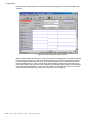
Selecting the Channel Configuration button from the Crakker Status dialog results in a second dialog
display detailing the Record, Alarm, and Channel information for the Run Program currently loaded
into the Crakker Memory.
Figure 4.7 Crakker Query Status... currently loaded Run Program Configuration
CCW Default File Paths
Default paths to be used for the Run Program and downloaded data files can be specified in the
Options dialog (Figure 4.3). Check to enable the default path(s) and browse or enter the desired
folder location.
4-7
Using the Crakker Logic / Timing Analyzer
4. Crakker Communications for Windows
Notes.....
4-8
Using the Crakker Logic / Timing Analyzer
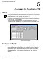
5. Programming the Crakker with CCW
5
P ROGRAMMING THE C RAKKER WITH CCW
Overview
The first step in implementing a Crakker Recording session is the development of a Run Program. A
Run Program is a small file that is developed within CCW, then transferred to the Crakker memory.
The Run Program contains configuration and operation information that the Crakker uses during its
data Recording function (e.g. the Trigger Word, alarm conditions, etc.)
The file is called a Run Program because it contains information that the Crakker utilizes while it is
RUNning during a Recording session. Run Programs developed in CCW are stored to disk with the
file extension `.RUN' (e.g. FILENAME.RUN).
The following sections detail the User set-up of Run Program parameters from within CCW.
To display the Program View window, click on the Program View button on the Button Bar or select
View | Program View from the menu.
Figure 5.1 Program View Screen
Run Program Configuration
Within the Program View Screen, settings are entered to result in a desired Run Program.
The first step in development of a Run Program is mentally defining the condition(s) desired that will
initiate the trapping of data into Crakker memory. These conditions will generally be indicative of a
fault or erroneous condition within the control system to be monitored and will vary in complexity
depending on the application. The conditions could range from something as simple as monitoring an
‘Emergency Stop’ button (or PLC input) from a production line to more complex triggering conditions
explained below. Once this Trigger condition is defined, development of a Run Program can
commence.
5-1
Using the Crakker Logic / Timing Analyzer
5. Programming the Crakker with CCW
Opening and Saving Run Program Files
Every Run Program has a filename with the extension `.RUN'. Typically, many Run Programs may be
developed and saved to disk and new Run Programs can be built by editing existing Run Programs
and saving them with a new name. Use the conventional Windows File | Open menu to open an
existing Run Program or New to start with a blank program.
After development of a Run Program, the program can be saved to disk view the Save button on the
toolbar or the File | Save As or Save menu selections.
Run Program Development
In the development of the Run Program, various text fields and logical condition statements are
completed. Upon completion, the program is saved and/or uploaded to the Crakker memory for
execution. Following is a discussion of the various parameters to be specified by the User in
development of a Run Program.
Program Description
Three lines of 16 characters each are provided for entry of a short description of the current Run
Program under development. This description will be saved with the Run Program. During a Status
display from the Crakker front panel, this description is displayed on the LCD immediately after the
name of the Run Program currently in Crakker memory. This description can then serve as a
reminder of the function of the associated Run Program.
Memory Saved Before Trigger
The Crakker allocates a certain block of its internal memory for storage of data. In the Recording
Enabled mode, the Crakker is constantly writing, then over-writing data to this block of memory while
it is waiting for the Record Trigger to occur. (A detailed explanation of the memory management
scheme is provided in “Appendix K: Memory Utilization / Loop Rate Theory” on page 8-21.)
The Memory Saved Before Trigger percentage value determines how the total Crakker data memory
is divided into Pre-Trigger and Post-Trigger data. When the Trigger occurs, the Crakker will continue
to write `post-Trigger' data to memory until the specified percentage is met. Upon fill of memory, the
Crakker then displays RECORD ENABLED <FINISHED> on its LCD and stops.
The percentages on the menu are approximate and specify the portion of the total data memory that
is allocated to data storage of transitions PRIOR to the Trigger (i.e. pre-Trigger data). Typically, the
events that occur just prior to a Trigger condition are of utmost interest in the troubleshooting
sequence.
NOTE: If a Trigger occurs before the specified pre-Trigger memory percentage is filled, the Memory
specification obviously will not be met...however, the amount of pre-Trigger data that was collected
will be retained.
Recording Mode
The Crakker can operate in a number of different Record Modes. Different modes allow for varying
operation and capability. Mode selection will vary depending on a number of setup parameters such
as number of channels, types and quantity of Triggers, and timing.
Figure 5.2 Recording Modes
5-2
Using the Crakker Logic / Timing Analyzer
5. Programming the Crakker with CCW
Note
The Record Mode selection offers four different modes of operation (8-SHORT, 8-LONG, 16-SHORT,
and 16-LONG) that include different combinations of these parameters. Different modes are offered
so the User can optimize the performance of the Crakker for the particular application.
Generally speaking, in the selection of the Record Mode, the Loop Rate (the rate at which the inputs
are latched into memory, checked for a Trigger match, then stored or discarded) is balanced against
the other parameters such as number of channels, number of triggers, etc. For example, more active
channels and/or enabled Triggers results in slower Loop Rates.
A detailed explanation of the Loop Rate can be found in “Appendix K: Memory Utilization / Loop Rate
Theory” on page 8-21. Although it is not critical that the information explained in this Appendix be
read, a basic understanding of the concepts involved will help in setup and application of the Crakker.
The Record Mode selection flow chart (Figure 5.3) can be used to select the desired Record Mode for
most applications.
8 vs. 16 Mode
The `8-SHORT' and `8-LONG' modes are supplied for 8 channels of input (one Pod) and the `16SHORT' and `16-LONG' modes are supplied for 16 channels (two Pods). (The `16-LONG' mode
is also used for Timed Trigger applications with 8 channels...discussed later)
Short vs. Long Mode... A Cursory Explanation
In general, the `SHORT' mode has been designed for the fastest Loop Rate with a compromise on
the total elapsed time window that can be stored to memory. Only one Record Trigger is allowed
for the `SHORT' mode.
`LONG' mode runs at a slower Loop Rate, but allows for a considerably longer total elapsed time
window to be stored to memory. In the `LONG' mode, up to three Record Triggers can be set and
up to two Alarm Triggers can be set. The total quantity of Triggers used affects the resultant Loop
Rate. The final Loop Rate can be checked using the Analyze Run Program command (“Analysis
of Run Program Performance” on page 5-16)
Note:
For simplicity in setup, Users may opt to always use the LONG mode for Crakker
applications where timing resolution of less than 1mS is not required.
Short vs. Long Modes... More Considerations
Note:
5-3
When the Crakker is running in the RECORD ENABLED mode, the Crakker stores data to
memory every time the Inputs have changed relative to the last time they were scanned. When
this occurs, the new Input Status and the elapsed time (from the last change on the Inputs) are
stored in memory.
In addition to storing when the Input Status has changed, the Crakker also stores data to memory
(even though the Inputs have not changed) after a fixed period of time has elapsed. This is
required to prevent the `elapsed time clock' (in software) from overflowing and the resultant loss of
the time base for the measurements.
In the `SHORT' mode, a clock that has a `shorter' time span is used. Conversely, a `longer' time
span clock is used in the `LONG' mode. Ultimately, this (generally) means that data memory will
be consumed at a faster rate using the `SHORT' mode than in `LONG' mode configured sessions
and the maximum window of time for which the Crakker can store data will be longer for the
`LONG' mode.
An exception to this occurs when monitoring inputs that are changing very quickly. In this case,
data is stored due to changes on the inputs, not due to an overflow of the `elapsed time clock' and
more data can actually be stored in memory in the `SHORT' mode since a `SHORT' sample
requires less memory space to store than does a `LONG' sample.
Using the Crakker Logic / Timing Analyzer
5. Programming the Crakker with CCW
START
IS TIMED TRIGGER
REQUIRED?
YES
16-LONG MODE
NO
IS "ANY CHANGE"
TRIGGER REQUIRED?
IS ALARM(S)
YES
REQUIRED?
NO
YES
MULTIPLE TRIGGERS
REQUIRED?
NO
8 OR 16 CHANNELS
8
8-LONG MODE
REQUIRED?
16
16-LONG MODE
16
8 OR 16 CHANNELS
REQUIRED?
8
IS REQUIRED LOOP
YES
RATE < 220uS?
NO
8-SHORT MODE
IS REQUIRED LOOP
RATE < 455uS?
8-LONG MODE
YES
N0
16-SHORT MODE
16-LONG MODE
NOTE: REFER TO TEXT FOR ADDITIONAL CONSIDERATIONS WITH RESPECT
TO LONG AND SHORT AND THEIR PARTICULAR RAMIFICATIONS ON THE
RECORDING WINDOW LENGTH.
Figure 5.3 Record Mode Selection Flowchart
Channel Setup
The Channel Setup region (Figure 5.4) of the Program View screen is used to configure channel
names, individual channel filtering (debounce), Record Triggers, Threshold Voltage (Vth) and Alarm
Triggers (that control two output relays built into the Crakker system base) which are maintained in
the Crakker Run Program.
The number of channels, Record Triggers, and Alarm Triggers available for configuration vary
depending on the Record Mode selected.
5-4
Using the Crakker Logic / Timing Analyzer
5. Programming the Crakker with CCW
Figure 5.4 Channel Setup Screen for 8-Short Mode
Channel Number
At the left edge of the Channel Setup Screen, the available channels are listed. Depending on the
Record Mode selected (8 or 16), Channels 1-8 for the `A' Pod and `B' Pod are listed.
Channel Description
Each Channel can be tagged with a short (16 characters maximum) descriptive name. In the field,
the User can review each of the Channel Descriptions on the Crakker display during a STATUS
display sequence. This can be of assistance when making the electrical connections from the Pod
to the field control points.
Debounce
The text boxes immediately to the right of the Channel Descriptions allow for a setting of
Debounce value for each channel. Four different levels of Debounce are available (0, 30, 50, and
70 mS). Use the pull-down menu to select the desired Debounce value for the channel.
The Debounce function enables different levels of filtering on each channels input to the Crakker.
The levels correspond to an approximate Time Constant which can be used as a figure of merit for
filtering and smoothing of input signals. Common applications and typical Debounce settings
follow:
SWITCH CONTACT DEBOUNCE
When mechanical switches, contactors, and relays electrical contacts `close', they generally
DO NOT switch together cleanly making immediate solid electrical contact. In actuality, they
go through a short cycle of bouncing together, opening, bouncing together, opening, etc. until
they finally come to rest in the closed position [Figure 5.5]. For a physically small switch, this
cycle may consist of 5 to 10 bounces all occurring within 20 mS of time...larger relays with
physically larger contacts and supporting arms impact harder and bounce longer.
5-5
Using the Crakker Logic / Timing Analyzer
5. Programming the Crakker with CCW
Figure 5.5 Contact Bounce
In switches utilized in DC (and to a certain extent in AC) circuits, this contact bounce will
translate into a rapid sequence of on and off voltage levels being detected by the Pod
circuitry. Figure 5.6 shows four channels of data collected from the same set of contacts on a
large relay with various amounts of Debounce specified. The first channel has no Debounce
and multiple transitions can be seen (zooming in on the data reveals six high/low cycles). If
no Debounce is used (i.e. 0) The Crakker will trap these rapid voltage transitions into memory
(and could possibly present a combination that fulfills a misleading TRIGGER condition). If
these transitions are not desired during the playback of the collected timing/state data, the
Debounce can be enabled to filter out these transitions.
Figure 5.6 Effects of Debounce Setting on Switch Closures
A value of 30mS can be used for small switches and a value of 50 or 75 for larger switches/
contactors may be required. Experimentation through a series of short data recording
sessions may be the best technique to use for selection of the optimum Debounce level.
5-6
Using the Crakker Logic / Timing Analyzer
5. Programming the Crakker with CCW
Note:
Use of the Debounce function actually slows down ("skews") the effective detection rate of
switch transitions by approximately the value selected. In critical high-speed troubleshooting
applications, more insight into the system performance may be gained by leaving this
Debounce value OFF (set to 0), with the trade-off that the data display may be considerably
more visually complex due to the multiple transitions at each switching. Time skew can
readily be seen between the different levels of Debounce in Figure 5.6.
MONITORING AC INPUTS
The actual voltage during one cycle on electrical nodes handling AC currents transitions from
the peak AC voltage through zero to a reverse polarity peak voltage then back through zero
to the peak voltage as seen Figure 5.7. If the Crakker is connected directly to an AC voltage
node, it will record these cycles as a continuous string of ON/OFF transitions when in
actuality, the node is in the `ON' state.
AC WAVEFORM
FULL WAVE
RECTIFIED (POD)
CRAKKER RECORD
OF AC INPUT
Figure 5.7 Pod Input Circuitry AC Rectification
Note:
5-7
For the technically curious, Pod input circuitry effectively full-wave rectifies the incoming AC
signals so the Crakker sees a signal that transitions from a positive voltage to zero and back
to the positive voltage without crossing under the zero...at twice the normal frequency (Figure
5.7).
The Debounce function can assist in overcoming this misleading AC input problem by filtering
the AC voltage into an ON and OFF state which corresponds to the presence or absence of
AC at the monitored node. Figure 5.8 illustrates the monitoring of an AC node with two
channels, one with and one without the Debounce enabled.
For typical 50/60 hz AC signals, a Debounce value of 30 mS will provide sufficient filtering
assuming that the Vth level is set to approximately 1/2 to 3/4 of the AC rms ON state value.
Use of Debounce settings other than 0 will result in time skew (delay in time) of the
transitions. This is illustrated Figure 5.8. Channel A1 has no Debounce enabled and
accurately portrays the timing of the first positive voltage detected on the input. Channel A2
with 30mS of Debounce enabled filters out the 60Hz cycles into one continuous ON period,
however note that its initial turn-on time is delayed by approximately 60mS.
Although the Debounce setting is 30mS, the combined effects of the duty-cycle of the AC
waveform above the Vth threshold (see “Vth Voltage Threshold” on page 5-8) serves to
impact the effective skew. In this example, a Vth of 10V was used for both channels and the
actual node voltage being measured is 13Vac (rms). With the 10V threshold, in a half period
(8.33mS) of the 60Hz cycle (16.666mS) the ON time was 5.6mS and the OFF time was
2.8mS. This imbalance serves to effect the Debounce time skew.
Using the Crakker Logic / Timing Analyzer
5. Programming the Crakker with CCW
Figure 5.8 Measuring timing on AC signals with and without Debounce
HIGH-SPEED APPLICATIONS OF DEBOUNCE
In very fast dynamic applications requiring ultimate speed and response to incoming signal
transitions, the Debounce should be set to 0mS. The corresponding data display will be
considerably more complex and data memory will be filled at a faster rate (especially in the
monitoring of AC nodes as data will be written to memory at the rate of 120 Records per
second for channels monitoring 60Hz AC).
AC signals `ON' states will appear as a series of regular spaced pulses...`OFF' states will
appear as steady low signals.
Vth Voltage Threshold
The column titled V-Thresh (Figure 5.4) specifies the approximate voltage thresholds that the
Crakker system uses to determine a logical ON or OFF level for that channel. Use the drop-down
list box to select the desired switching threshold for each channel.
Typically, the Vth setting should be set at approximately 1/2 to 3/4 of the voltage present at the
control system node of interest. For example, on a node that swings between 0 and 5VDC, a
setting at 3V should provide good performance. On an AC signal node that swings between 0 and
120VAC (rms), a setting of 80 or 90V should give good performance. When monitoring AC nodes,
keep in mind that a Debounce setting may also be required (see prior section on Debounce).
Additional information on the Vth setting is provided in “Pod Switching Thresholds... Vth Setting”
on page 3-2. For convenience, the Vth Threshold Table (Figure 5.9) is duplicated in both sections.
Note that the voltage specifications are approximate and will vary slightly between units.
5-8
Using the Crakker Logic / Timing Analyzer
Programmed Vth Level
(Vdc)
Approximate
Approximate
OFF to On Voltage (Vdc) ON to OFF Voltage (Vdc)
2.0
2.0
1.3
2.5
2.5
1.7
3.0
3.0
2.2
4.0
4.0
3.0
5.0
5.0
4.0
6.0
6.1
4.6
8.0
8.1
6.0
10.0
10.0
6.9
15
15
10
20
19
13
25
25
19
30
30
21
40
40
31
50
50
40
60
58
48
70
70
59
80
82
70
90
90
78
100
100
87
110
112
101
120
122
111
130
130
118
140
139
127
150
150
140
160
158
147
170
169
159
180
182
174
190
190
182
200
198
190
210
212
205
Figure 5.9 Approximate Pod Voltage Thresholds (V-Thresh) Switch Points
Note:
Tip:
The Pod input channels will NOT be damaged by setting the Vth level incorrectly for the
application.
The 32 levels of Vth thresholds are provided within the Crakker to facilitate further control system
troubleshooting / analysis with the Crakker system. For example, droops in power supply voltages
can be detected by utilizing multiple Pod channels configured with a sequence of Vth settings.
Record Triggers
While the Crakker is running in the RECORD ENABLED mode, it is constantly reading the input
states (via the Pods) and comparing them to a Trigger word(s) contained in the Run Program. A
Trigger is a combination of Input Channel activity defined by the User to initiate an Alarm
Logic Beach Incorporated www.logicbeach.com
5-9
5. Programming the Crakker with CCW
(discussed later) or Record function. When the condition of a Record Trigger are met, a marker is
put into the file and timing and signal waveform data is stored surrounding the Trigger. Depending
on the setting for the allocation of memory (see“Memory Saved Before Trigger”) data before and/
or after the trigger condition will be saved.
The Trigger Configuration screen (Figure 5.10) allows the User to set the Trigger conditions for the
initiation of Recording (Record Trigger). Depending on the Record Mode selected on the
Recording Mode list box, different quantities, and types of Triggers will appear for editing on the
Trigger Configuration screen. In the most powerful Record Mode... 16-Long, 3 Record Triggers (16
channels), 2 Alarm Triggers (16 channels), and the Timed Trigger can be utilized. In contrast, in
the fastest (but most limited) Record Mode... 8-Short, only one Record Trigger is allowed (8
channel).
In Record Modes with multiple Record Triggers allowed (e.g. 8-Long and 16-Long), the Triggers
for the Record function are logically OR'd together. For example, if a User sets up all three Record
Triggers (8-LONG or 16-LONG mode) in a Run Program, loads the Run Program into the Crakker
then Enables Recording, the Crakker will Trigger if Record Trigger 1 OR Trigger 2 OR Trigger 3
occurs.
In the 16-Long Record Mode, a Timed Trigger is also allowed as a fourth possible Record Trigger.
If it is setup and enabled the Timed Trigger is logically OR'ed with the other utilized Record
Triggers.
Figure 5.10 Record Trigger Configuration Section of Program View
Alarm Triggers
Quite similar to the Record Triggers, two Alarm Triggers (Figure 5.11) are also provided which
control two output relays built into the Crakker. These Alarm Triggers are available only in the 8Long and 16-Long Record Modes.
Each of the two Alarms has a single associated Trigger that will cause its Alarm to turn ON when
the Trigger conditions are met. Unlike the Record Triggers, only one Trigger word is available for
each alarm hence no logical ORing can be programmed. A special alarm mode, where the Alarm
follows the Record Triggers is provided ( Any Record Trigger). Similar Trigger conditions and
editing techniques are used for the Alarm Triggers as are used in configuring the Record Triggers.
5-10
Using the Crakker Logic / Timing Analyzer
Figure 5.11 Alarm Trigger Configuration
Six types of Trigger Logic are supported by the Crakker:
1. DON’T CARE
If Don’t Care is selected for a channels entry in a Trigger list box (Figure 5.13), the state and
transitions associated with that channel are ignored by the Crakker during the Trigger
determination process. All channels that are not to be involved in determining a Trigger
condition should be set to Don’t Care.
2. STATE TRIGGER LOGIC
Input Channel States refer to an input that is either High (On) or Low (Off) when scanned by
the Crakker. An example of a State type Record Trigger is demonstrated in Record Trigger 3
in Figure 5.10:
Trigger when Rotation Motor is ON (High) and the Head
Ejector is ON (High)
In the Trigger list box, State Triggers are listed as High or Low (Figure 5.13).
3. TRANSITIONAL / EDGE TRIGGER LOGIC
Input Channel Transitions refer to an input to the Crakker that changes from ON to OFF (High
to Low) or OFF to ON (Low to High) relative to the last scan of that input. Transitions from
OFF to ON are referred to as ‘Rising Edge’ transitions and ON to OFF are referred to as
`Falling Edge' transitions (Figure 5.12).
An example of a Transitional Trigger is shown in Figure 5.10 Trigger 2:
Trigger when the Rotation Motor is OFF (Low) and Index
Detent actuates (transitions from Low to High)
In the Trigger list box, Transitional / Edge Triggers are listed as Rising Edge or Falling Edge
(Figure 5.13).
Note that in this example, by using a Transitional Trigger, the Index Detent may already be
ON when the Crakker is ENABLED and the Crakker does not Trigger. Because a
Transitional Trigger is used, the Crakker does not Trigger until the Index Detent turns ON (in
this case, the Index Detent must turn OFF then turn back ON). In contrast, if a State Trigger
Logic Beach Incorporated www.logicbeach.com
5-11
5. Programming the Crakker with CCW
had been used for the Index Detent, the Crakker would have Triggered immediately upon
ENABLING RECORDING as the Index Detent level was already steady state ON.
ON
RISING EDGE
SIGNAL
FALLING EDGE
SIGNAL
OFF
ON
OFF
Figure 5.12 Transitional or Edge Triggers
4. TIMED TRIGGER LOGIC
A special Timed Trigger is provided that operates only on Channels A1 and A2. This Trigger
can be set to initiate Recording if the Input to Channel A2 transitions too soon or too late after
a previously defined transition of Input on Channel A1 (e.g. a Trigger could be set to initiate
recording if a pump started `short cycling', turning ON and OFF faster than once every 60
seconds). The Timed Trigger is only available in the 16-Long Record Mode. Nine
combinations of Timed Trigger are available. Details on the Timed Trigger configuration and
use are covered in the following section, “Timed Trigger Details” on page 5-13.
5. TRIGGER ON ANY CHANGE
This Trigger can be set to initiate Recording as soon as any one of the inputs changes. The
Record Mode must be set to 16-LONG and Timed Trigger cannot be used simultaneous with
`Trigger on Any Change'.
In the Trigger list box specify Any Change (Figure 5.13).
6. ALARM FOLLOWS RECORD TRIGGER (APPLIES TO ALARM TRIGGERS ONLY)
Alarm Trigger can be set to follow the Record Triggers. If utilized, the Alarm output(s) will be
set if any of the Record Triggers are met. This function can be used to sound an annunciator
or light a warning light in the event that a Trigger condition has been met... drawing attention
to the Crakker.
To utilize this trigger condition, select Any Rec Trigger for the alarm (Figure 5.14).
Combinations of State, Transition and Timed Trigger conditions can be implemented for more
complex Triggering applications as follows:
Trigger when Pump 1 is ON and Valve 7 is OFF and when
Pressure Switch 8 turns ON or if the Temperature regulation
Switch turns ON more frequently than once per 100mS.
5-12
Using the Crakker Logic / Timing Analyzer
Figure 5.13 Record Trigger Options
Figure 5.14 Alarm Trigger Options
Trigger Relationships Reviewed
Record and Alarm Trigger conditions are logically AND’ed within a single trigger’s vertical column.
For example, in Figure 5.10, Channel A1 and Channel A4 have to be HIGH for the trigger condition
to be met.
Triggers defined in columns are logically OR’ed. For example, in Figure 5.10, all three Record
Triggers are used. So if conditions in Trigger 1 OR Trigger 2 OR Trigger 3 occur, data surrounding
the trigger will be logged to memory.
Timed Trigger Details
The Timed Trigger can be configured as a fourth Record Trigger and logically OR’ed with up to
three conventional logic type (Transitional or State) Triggers. The Timed Trigger is available only
in the 16-Long Recording Mode. When the Timed Trigger is enabled, the Trigger rows associated
with Channels A1 and A2 are highlighted.
The Timed Trigger applies only to the signals received from Pod channel A1 and A2. Specified
activity of Channel A1 initiates the timing check for the following activity of the Channel A2 Input. If
a fault condition is seen, the Timed Trigger becomes valid and Recording is enabled. If no fault
condition is seen, scanning of inputs continues and Channel A1 input will be monitored for the
specified activity to initiate the next timing check.
Two parameters must be specified for operation of the Timed Trigger, the Type and the Timing.
The Type specifies the sequential pair of Channel A1 and A2 input transitions that must occur for
the Timed Trigger to be valid. The Time specifies the allowable time in the logic sequence to
make the Trigger valid.
Logic Beach Incorporated www.logicbeach.com
5-13
5. Programming the Crakker with CCW
Figure 5.15 Timed Trigger Type and Timing Selection
TYPE SELECTION
Nine different types of Timed Trigger operation are available via a list box in the Timed
Trigger section (). An understanding of Timed Triggers may be best developed by example.
Following are further explanations of a few of the Timed Trigger functions. Additionally, timing
diagrams are shown in Figure 5.16.
A2 ON too LATE after A1 ON
The trigger condition is met if the time between the ON transition of Channel A1's input
and the ON transition of Channels A2's input exceeds the specified Trigger TIME.
This trigger could be used to trap actuation delays in the actuation of a part removal
mechanism after a flawed part has been detected on a high-speed conveyor line.
Additionally, this function could be used to trap overly long periodic loop rates in a time
critical PLC program. Too much delay between a PLC input asserting and a
corresponding output asserting can be detected.
Tip
A2 OFF too EARLY after A1 ON
Trigger condition is met if the time between Channel A1's input transition from OFF to
ON and the following Channel A2's transition from ON to OFF is shorter than the Time
specification.
At the packaging end of a production line, a glue applicator is to apply glue to a moving
product case for a stroke that lasts 800mS after detection of the presence of the case.
This trigger could be used to trap short cycles of glue application.
Note that for some applications, both channel A1 and A2 can be connected to the same
control node. In this way, a ‘too short’ or ‘too long’ pulse could be detected on a control
line by using the A2 ON too Late after A1 ON (pulse too long) or the A2 OFF too Early
after A1 ON (pulse too short) triggers.
TIME SELECTION
Within this list box, specify the time to be used in the Timed Trigger. Format is indicated in
Minutes, Seconds and Milliseconds.
5-14
Using the Crakker Logic / Timing Analyzer
1
A1
A2 ON too LATE after A1 ON
TRIGGER if T > Timed Trigger Value
A2
T
2
A1
A2 OFF too LATE after A1 OFF
TRIGGER if T > Timed Trigger Value
A2
T
3
A1
A2 ON too LATE after A1 OFF
TRIGGER if T > Timed Trigger Value
A2
T
4
A1
A2 OFF too LATE after A1 ON
TRIGGER if T > Timed Trigger Value
A2
T
5
A1
A2 ON too EARLY after A1 ON
TRIGGER if T < Timed Trigger Value
A2
T
6
A1
A2 OFF too EARLY after A1 OFF
TRIGGER if T < Timed Trigger Value
A2
T
7
A1
A2 ON too EARLY after A1 OFF
TRIGGER if T < Timed Trigger Value
A2
T
8
A1
A2 OFF too EARLY after A1 ON
TRIGGER if T < Timed Trigger Value
A2
T
Figure 5.16 Timed Trigger Types
Logic Beach Incorporated www.logicbeach.com
5-15
5. Programming the Crakker with CCW
Alarm Output Operation
Two User programmable output functions are available for the logic associated with the actual
Alarm output signal... which controls the output relays within the Crakker, Latched and Momentary.
Figure 5.17 Alarm Output Operation
LATCHED
When Alarm Trigger conditions are met, the associated Alarm will turn ON. If the Alarm is
configured in the LATCHED mode, the Alarm will stay ON indefinitely once it has been
Triggered regardless of continued activity on the Channel Inputs. The Alarm can be disabled
by implementing a Reset of the Crakker or by switching it OFF via the Crakker System Base
front panel manual Alarm Control Switch (“Alarm Control Switches (10)” on page 2-6).
MOMENTARY
Note
If the Alarm is configured in the Momentary mode, the alarm will turn ON when the Alarm
Trigger conditions are met, then OFF as soon as the specified Trigger conditions are no
longer met.
For the alarms to function in either mode, the Alarm Control switches on the front panel of the
Crakker must be in the RUN position.
Analysis of Run Program Performance
After development of a Run Program, an inquiry into the expected performance of the program can be
performed. The Analysis Report is provided to analyze and report to the User a summary of the
expected performance from the Run Program currently under development. After reviewing the
Analysis Report, the User may make changes in the Run Program to change or optimize the desired
performance, then rerun the Analysis Report...noting the effects of the changes.
With the aid of the Analysis feature, the Run Program's performance within the Crakker can be
evaluated and `fine-tuned' to the application prior to saving and loading into the Crakker's memory.
To perform an analysis of a Run Program, a Crakker must be connected via a serial link to the PC
running CCW. For an analysis, CCW requires timing and memory information that is maintained
within the memory of each Crakker System Base. This information is utilized in the performance
calculations and may vary with different Crakker System Bases and memory configurations.
Although communication with the Crakker is required to utilize the Analysis Report function, the
Analysis is performed on the Run Program under development within CCW, NOT on the Run
Program currently loaded in the Crakker memory.
The following information is calculated from the current Run Program settings and displayed in the
Analysis dialog (Figure 5.18):
5-16
Using the Crakker Logic / Timing Analyzer
Figure 5.18 Analyze Run Program dialog
Enabled Triggers and Alarms
A listing of the types and quantity of triggers utilized in the Run Program being analyzed.
Active Channels
8 or 16
Loop Rate
With the current combination of Alarms, Triggers, Channels enabled, and Record Mode selected,
the Active Inputs will be read once per Loop Rate. Changing any of the above mentioned
variables will effect the Loop Rate. Refer to “Appendix K: Memory Utilization / Loop Rate Theory”
on page 8-21 for a detailed explanation of the Loop Rate.
Maximum Recording Window
The MAXIMUM window of time that could be stored in data memory. In use, this window of time
will be shorter due to the recording of Input Transitions, however, this value can be used as a
relative figure of merit for comparison between different Run Program configurations.
Maximum Recording Time Before and After the Trigger
Indicates the effect of the selected Memory Split setting within the Record Program displayed on a
time basis.
Logic Beach Incorporated www.logicbeach.com
5-17
5. Programming the Crakker with CCW
Notes....
5-18
Using the Crakker Logic / Timing Analyzer
6. Captured Data Display and Output
6
C APTURED D ATA D ISPLAY AND O UTPUT
Overview
In the Data Display View, a file is loaded into CCW (either directly from the Crakker memory or
opened from file using the File|Open Menu) and viewed (Figure 6.1). In the Data Window, logic
comparisons between channels can be performed, absolute and relative timing measured, and fault
conditions identified. A flexible zooming and panning function allows for detailed analysis of timing
data. Channel’s display order and colors can be changed.
Timing Information
Display Calibration Status
Position Indicator
Run
Program
Name
Elapsed
Time Axis
Data
Window
Status Bar
Channel Names
Loop Rate Indication
Trigger Marker
Delta Time Slice
Figure 6.1 Display of Recorded Timing Data (Data View)
6-1
Using the Crakker Logic / Timing Analyzer
6. Captured Data Display and Output
Display View Screen
Data Window
Timing displays representing each channel are displayed in the Data Window horizontally with a Hi
or Lo state. The state represents the Channels voltage level at that point in time relative to the
Voltage Threshold programmed into the Run Program.
Channel Numbers and Descriptions
Along the left edge of the Data Window (Figure 6.1) are Channel Numbers and their associated
descriptions/names. The Channel numbers correspond to the Isolation Pod channels… the letter
prefix indicates either Pod A or Pod B (if equipped with two Pods). Associated channel
descriptions carry over from descriptions assigned during development of the Crakker Run
Program. To view Channels B1 through B8, scroll the Data Window using the slider on the right
edge of the Data Window.
Channel Display Order
The order of the channel display (top to bottom) by default is per the Channel’s associated Pod
Number (e.g. A1, A2, A3...). To facilitate inter-channel timing measurements, the top to bottom
ordering of channels can be simply changed.
To move a channel to a different location in the top to bottom order, simply click on the Channel
Number/Description box and drag the channel up or down to the desired location.
Channel Visibility
Right clicking on the Channel Number/Description box will display two menu choices. Select
Channel Visibility and the Channel Visibility dialog (Figure 6.2) will display. Highlight channels,
then select Show or Hide to toggle channel visibility within the Data View.
Alternatively, use the menu and select View | Channel Visibility.
Figure 6.2 Channel Visibility dialog
Channel Color
Right clicking on the Channel Number/Description box will display two menu choices. Select Color
Options and the Channel Color dialog will display (Figure 6.3). Set the desired color for each
channel with the color palette drop-down by each channel.
6-2
Using the Crakker Logic / Timing Analyzer
6. Captured Data Display and Output
Figure 6.3 Channel Display Color dialog
Note that the global default colors used when opening a file can be set from within the File |
Options | Trace Colors menu.
Elapsed Time Axis
Along the top edge of the Data Window is the Elapsed Time Axis. As the data is zoomed or
panned (see following Navigation section), the time resolution tic marks on the time axis will
change.
Trigger
Tip
If the Run Program loaded into the Crakker utilized the Trigger function, a vertical red Trigger
Marker will display within the Data Window, passing vertically through all of the channels
waveforms.
At any time, keying <F4> or Menu selection View | Scroll to Trigger will jump the display to center
up on the Trigger marker.
Data Display Navigation
The Crakker system is capable of logging millions of channel transitions… hence CCW is equipped
with powerful data display capabilities. Zoom can be used to view timing details and the Pan
commands allow easy navigation throughout a large file. The Position Indicator window aids in
maintaining a ‘big picture’ overview of the currently displayed data.
Following are details on the use of these data display navigation features.
6-3
Using the Crakker Logic / Timing Analyzer
6. Captured Data Display and Output
Zoom Controls
Pan Controls (Pan Left)
Trigger location
Complete Data File
Scroll Bar Accessible /
Viewable Data
Figure 6.4 Position Indicator with Zoom and Pan Control Buttons
Zoom In / Zoom Out
Whenever the Data View is displaying valid sample data, the Zoom In command can be used to show
more detail within the Data Window. Zooming in will result in less timing information being displayed
but at a higher time detail. To Zoom In (or Out) use the Zoom buttons (magnifying glass icons) on the
button bar or the equivalent menu commands (View | Zoom In).
Once you have zoomed in beyond a certain point, the Data Window cannot display all of the data
(which might be hundreds of millions of individual samples). At this point, only a section of all sample
data will be displayed within the active Data Window as indicated in the Position-Indicator bar at the
top right of the screen (directly under the Zoom/Pan controls).
Menu selections (or Function Keys) can be used to jump quickly between the maximum zoom display
level (View | Maximum Zoom) and minimum zoom display level (View | Minimum Zoom).
Position Indicator
Due to limits within the Windows environment, the full range of very large files can not be completely
accessed start to finish via the slider on the bottom Scroll Bar. The Position Indicator represents the
full data file…. The left edge being the start and the right edge being the end of the file. At low levels
of timing resolution (i.e. zoomed out) the scroll bar at the bottom of the screen allows movement
through the complete file. Zooming in to a finer timing detail will eventually result in a limitation in the
Scroll Bar range to less than the full file. The Position Indicator shows this condition when it displays
with a blue band indicating the data within the full file that can now be accessed by the Scroll Bar
slider at the bottom of the screen.
A red vertical line in the Position Indicator indicates the location of the trigger within the file. Note that
at any time, the view can be centered on the Trigger point by selecting View | Scroll to Trigger from
the Menu Bar.
Pan Left / Pan Right
Panning control buttons move the scrollable range (the blue band) left and right through the data
file… moving/stepping the region that is accessible with the Scroll Bar about within the full data file.
Alternatively, use the <Page Up> and <Page Down> keys.
Data Display Timing:
Various timing information is available in the Data Display View. Across the top of the Data Window is
a time axis for visual reference of elapsed time from the start of the file (time 0).
On-screen text boxes display:
6-4
Using the Crakker Logic / Timing Analyzer
6. Captured Data Display and Output
Cursor Time
When the mouse pointer is moved over the Data Window, a green vertical cursor appears and
moves with the pointer. The elapsed time from the start of the file is displayed with in the Cursor
Time box. The time display format is Day, HH:MM:SS.ddd.d where H corresponds to Hours, M to
minutes, S to seconds, and d to decimal seconds (milliseconds to microseconds).
Real Time
As the vertical cursor moves over timing data, the absolute real time is also displayed. Here, the
date as well as the time in HH:MM:SS format is provided. Note that when zoomed in to a high
level of time resolution, this Real Time display may not appear to update… this is because all of
the displayed data is within a one second slice of time.
Delta Cursor Time
Tip:
Time measurements of a waveform or between waveforms can easily be measured with the Delta
Time feature. The Delta Cursor Time displays the length of time from the start to the end of a
highlighted slice of the data. To highlight a section of the timing display, left click and drag the
vertical cursor across the displayed timing data. Upon release of the mouse button, a green
vertical band will display. The time encompassed by the band will be displayed in the Delta Cursor
box.
To measure delta times at higher resolutions, the timing display can be zoomed (see section on
Zoom controls following) to a desirable level and then the highlighting of the desired time slice can
be done. As the cursor is dragged to the edge of the Data Window, the data will start scrolling…
allowing access to timing data beyond the current view.
To scroll controllably through a timing sequence (that extends beyond a single monitor screen
display width) while defining a Delta Time, mark the starting point of the desired Delta Time slice
and while holding the mouse button down, use the left and right arrow keys and the PageUp and
PageDown keys to move through the timing display. When the desired end point of the Delta
measurement is found, release the mouse key and the green time slice band will display.
Display Timing Considerations
In the review of data, it is important to keep in mind the net time resolution that can be achieved using
the Crakker system and its ultimate ramifications during the display of the collected data.
Time Resolution - Loop Rate
The ultimate absolute time resolution achieved by the Crakker during a Recording session is specified
as the Loop Rate. The Loop Rate depends on the Record Mode, quantity, and type of Triggers
employed in the Run Program.
The Loop Rate used during recording of the currently displayed data file is displayed in a pane on the
Status Bar in the lower right corner of the screen (Figure 6.1). The Loop Rate is further described
and discussed in the Program View section of this manual. (Refer to “Appendix K: Memory Utilization
/ Loop Rate Theory” on page 8-21 for a detailed discussion of the Loop Rate.)
During operation of the Crakker, all of the active inputs to the Crakker are latched and read each
period of time specified by the Loop Rate. Therefore, in the display of collected timing data, the
smallest time resolution that can be meaningfully displayed is this Loop Rate value.
Calibrated / Uncalibrated
In the upper left corner of the Data View Window (Figure 6.1) is the Calibration Indicator. When
making critical time measurements on displayed timing data using the Cursor or Delta Time functions,
it is imperative that the data display be expanded to the Calibrated level for maximum timing
measurement resolution and accuracy. This bar displays one of two states:
• Calibrated indicates that the currently displayed time base equals or exceeds the Loop Rate
used during Recording of the data.
• Uncalibrated indicates the currently displayed time base is longer than the Loop Rate.
6-5
Using the Crakker Logic / Timing Analyzer
6. Captured Data Display and Output
When making critical time measurements, the screen can be Zoomed In to the Calibrated level,
marked, then Zoomed Out (to facilitate rapid movement of the Cursor), the Cursor moved, then
Zoomed In again to the CALIBRATED level. Time resolution will be retained throughout the Zooming
processes.
Viewing Associated Run Program
During the review of a recorded data, it can be advantageous to know the details and settings used in
the Crakker Run Program during the data collection process. Quick access to this information is
available via the Crakker | View Run Parameters menu selection. Upon selection, a dialog will open
that includes the associated Run Program particulars and trigger conditions.
If desired, the displayed parameters can be exported to a new Run Program using the Export button
at the bottom of the dialog. This will generate a new Run Program that can be loaded into the Crakker
and used. The resulting Run Program will be identical to the original Run Program used in the original
data collection phase.
Printing
From within CCW, timing data can be printed on the installed Windows printer. A number of printing
methods can be used to meet the desired hardcopy annotation needs. Printing is performed from the
conventional File | Print menu (or Print and Print Preview buttons on the Button Bar) and the follow-on
Print dialog. Typically, it is desired to select Landscape mode for timing printouts.
Print Complete Data File
The full data file can be printed on consecutive sheets by selecting the Print Range | All xxx Pages
radio button. The file will be printed at the currently displayed Zoom level.
Note:
Be aware that large files printed at higher Zoom levels can result in 100’s of printed sheets!
Print a Range of Pages
Prior to printing, display the data at the Zoom level desired on the printout. To print just a range of
pages of the data file, select the Print Range | Pages from... radio button and specify the pages
desired in the appropriate text boxes.
Figure 6.5 Windows Print dialog
Print a Selected Page
To print just a single page from within CCW, Zoom into the desired printout level, identify the time
range on the Time Axis, then select File | Print Preview menu choice. From within the Print Preview
6-6
Using the Crakker Logic / Timing Analyzer
6. Captured Data Display and Output
dialog, step ahead until the desired data page is displayed (observe the Time Axis to locate your
position in the file as data may or may not be visible in the Print Preview dialog). When the desired
data is displayed, click on the Printer button and that page will be sent to the printer.
Print a Selected Range of Data
A specific range of data that may span one or more pages can be printed by highlighting, then
printing. Using the Delta Cursor, highlight the range of data to be printed. Then from the Printer dialog,
select the Print Range | Selection radio button choice and hit OK to print. The highlighted selection
area will be printed.
Exporting Data to a CSV File Format
Displayed data can be exported to a *.CSV (comma delimited file) format from using the menu File |
Export selection. A dialog opens allowing the currently displayed file to be saved as a file with the
CSV extension. CSV files can be opened within various other applications such as spreadsheets such
as Excel (Figure 6.6).
Figure 6.6 Excel Display of a CSV Converted Data File
6-7
Using the Crakker Logic / Timing Analyzer
6. Captured Data Display and Output
Notes....
6-8
Using the Crakker Logic / Timing Analyzer
7
U TILIZING THE C RAKKER
Overview
The prior sections of this manual provided detailed information on the three components that make up
a Crakker Logic/Timing Analyzer System, the Crakker System Base, the Isolation Pod(s), and CCW,
the Crakker Communications Software. Building on that previously presented material, this section,
describes a typical sequence of steps that would be performed in an application of the Crakker.
Assess The Problem
When a problem with a control system is detected, some deductive troubleshooting thought needs to
be applied before the Crakker can be brought into action.
Minimize The Variables
In large, complex, control systems, it is imperative that some basic reduction of the `playing field' be
performed prior to applying the Crakker. Attempt to identify and limit your studies to the variables,
sensors, switches, outputs, etc. that could be related to the problem. For example, if a single PLC is
controlling material feed conveyors, stamping equipment and material scrap removal, concentrate
your studies on the aspect of the production line that is causing the problem.
However, use caution in limiting the scope of the troubleshooting quest. Keep an open mind as many
problems can be the result of some fairly intricate inter-related stimuli. Non-judicious limiting of the
troubleshooting effort may hide some key indications of the problem and unduly prolong the
troubleshooting process.
Determine A Trigger Condition
The best way to trap problems in unattended or intermittent applications is by using the Crakker's
powerful Triggering capabilities. When the Crakker sees the Trigger condition, it will trap the
sequence of events surrounding the fault for review on the PC. Triggers can come from a number of
sources:
System Signal
An ideal Crakker Trigger situation exists where a known combination of I/O occurs on the PLC just
before, during, or after a fault condition. This combination can be programmed into the
conventional Record and Alarm Triggers of the Crakker Run Program (e.g. maybe two outputs
should never be ON at the same time).
Logic Beach Incorporated www.logicbeach.com
7-1
7. Utilizing The Crakker
System Alarm
The Control system may already have an alarm output that asserts upon a problem... for example,
an emergency shutdown signal (E-Stop), overload warning horn, etc. that could be used by the
Crakker to Trigger.
External Trigger
In some applications, an external Trigger sensor or device may need to be added to the Crakker
system to detect a fault condition. When the external Trigger device sees a fault condition, it
would then provide a Trigger signal to the Crakker Pod trapping data into memory. For example, a
low-voltage moisture detection switch may be employed under a liquid filling line...if any containers
are over-filled, the moisture detector would provide a Trigger signal to the Crakker, trapping data in
Crakker memory.
Manual Trigger
In many operator attended cases, a fault condition may be very obvious to operators near a
process or line. In this case, an instructed operator could press the Stop button on the Crakker to
end the Recording Session and trap data in memory. In manual Trigger applications, it is
important that the Crakker be stopped before valuable data in memory is overwritten. In the
fastest mode (8-Short Mode) this occurs within approximately 14 minutes.
On rare occasion, it may be nearly impossible to identify an appropriate Trigger to use. In these
cases, it may be necessary to resort to iterations of various Triggers to determine the problem.
However, judicious selection of the Trigger for each attempt should gain valuable insight into the
problem....or at least, eliminate some variables.
Develop The Run Program
After an appropriate Trigger condition has been identified, the Run Program to be used by the
Crakker can be developed. Boot up the PC running the Crakker Communications (CCW) program
and select the Program View mode to start developing a Run Program.
Throughout the development of the Crakker Run Program, the Analysis feature should be used to
evaluate the expected performance of the Run Program. Remember that a Crakker must be
connected via the serial port to use the Analysis function.
Filename / Description
Choose a logical Filename and three line Program Description that will assist future Users in
determining the utility and application of the Run Program.
Memory Saved Before Trigger
Select the desired memory split by specifying the amount of total data memory to be used for
storage of Pre-Trigger data.
Record Mode
The selection of the Record Mode can be made through utilization of the Record Mode Flowchart
[Figure 5.3].
Trigger / Channel Configuration
After the Record Mode has been selected and the desired mode highlighted, the Timed Trigger,
Record Trigger(s), and Alarm Triggers can be configured.
7-2
Using the Crakker Logic / Timing Analyzer
Timed Trigger
In configuring the Timed Trigger, the TYPE must be selected before the TIME can be set.
Additionally, remember that the Timed Trigger function only functions on the A1 and A2 input
channels. To use the Timed Trigger, the LONG-16 mode must be selected.
Debounce
Enable the Debounce appropriately if AC inputs are being monitored or if mechanical switch
bounce is to be rejected. Remember that the Debounce filtering slows down the response time of
the Crakker. In trapping inputs that are extremely fast, it may be desirable to disable (i.e. set to `0')
the Debounce filtering.
Voltage Threshold, Vth
Select the Vth setting for each of the connected channels. For most applications, a Vth setting of
approximately 1/2 to 3/4 of the ON voltage will suffice.
Channel Descriptions
The Channel Descriptions can be displayed on the Crakker LCD during field installation.
Choosing logical, descriptive names for each channel can greatly simplify the field installation
process.
Record And Alarm Triggers
Depending on the Record Mode selected, various quantities and types of Triggers are available.
After configuring the desired Triggers, use the Run Program Analysis button or menu and perform
performance analysis of the configuration. If speed is a concern, minimizing the use of channels,
Triggers, and Alarms will optimize the Loop Rate [“Appendix K: Memory Utilization / Loop Rate
Theory” on page 8-21].
Save / Exit
After development of the Run Program, save it to disk using the conventional Windows Save or
Save As buttons or menu selections.
Uploading The Run Program
Connect the Crakker to the PC serial port with the provided RS-232 cable and adapter. From the
CCW Program View window, open the desired Run Program from disk (if not already open within
CCW) then select the Upload Program to Crakker button to transfer it to the Crakker’s memory.
After sending the Run Program to the Crakker, use the Crakker | Query Crakker Status menu
selection to verify proper time/date and Run Program configuration.
Isolation Pod Setup
Carry the Crakker and Isolation Pod(s) to the site of the control system to be analyzed. Before
Connecting Any Pod Leads To High Voltage, connect the provided low voltage power supply to the
Crakker System Base power jack.
Logic Beach Incorporated www.logicbeach.com
7-3
7. Utilizing The Crakker
Press the Status button on the Crakker System Base and the Status display sequence will
commence. When the LCD displays Press Status to Display Ch Names press the Status button again.
The LCD will then display and hold the first Isolation Pod channel name as entered into the Run
Program. Pressing the Status button again steps the display through each of the channels. With this
sequence, the Quick Connect Pod Leads can be connected to the various nodes on the control
system under test.
************************ NOTE ***************************
It is highly recommended that if at all possible, power be
disconnected from the control system to be monitored
before connecting any Pod test leads. This is to minimize
the risk of electrical shock or erratic / unexpected operation
of the equipment under control.
***************************************************************
*********************** Caution ****************************
Extreme care should be exercised in connecting the Pod
Quick Connect leads to any high-voltage nodes. The probe
tips have exposed conductive surfaces when installed.
Mishandling could result in fatal electrical shock.
Before making any connections to a control system, insure
that the addition of the Pod circuitry will not interfere with the
normal control function. Refer to Chapter 3 and Appendix L
for additional circuit connection details. Do Not Hesitate To
Call Logic Beach For Technical Support Assistance.
**************************************************************
Connect the Pod low voltage output cable (multi-conductor cable extending from the bottom of the
box) to the mating connector on the Crakker System Base. If only one Pod is used, connect its cable
to Port A. Insure that the connector retaining screws are securely tightened.
Power up the control system under test and watch for any erratic operation indicating operational
interference from the Pod circuitry. The Crakker Monitor button can be pressed to observe the cycling
operation of the control system signal nodes.
Alarm Output Connection
If Alarms are utilized, pre-wire the Alarm pigtail assembly (refer to Appendix D) to the low-voltage
alarm devices then plug the pigtail into the Alarm Output connector on the Crakker System Base. The
Alarm functions can be tested by switching the Manual Alarm switches to the momentary TEST
position. After testing, be sure to leave the Alarm Switches in the RUN position to allow the Crakker
to control them per the loaded Run Program Alarm Trigger logic.
Enable Crakker Recording
After checking that the Crakker and Pod have been correctly installed and connected, press the
Enable button and the Crakker will roll through a number of displays, then proceed to start reading the
inputs, waiting for the pre-programmed Trigger condition(s). If the Crakker detects any errors, they
will be displayed on the LCD at this time. For this reason, it is a good practice to watch the LCD after
pressing Enable until the WAITING message is displayed, indicating a proper initiation of the
Enabling of Recording.
7-4
Using the Crakker Logic / Timing Analyzer
Collected Data Download
The Crakker System Base should be checked regularly. A lit green light on the front panel indicates
that the Record Trigger has been met and data is stored (or currently being stored) in memory. When
the complete Crakker memory has been filled, the LCD will display DATA RECORDED <FINISHED>.
After Triggering (and fill of memory if Post-Trigger data is desired) the Crakker System Base can be
powered OFF (memory will be retained) and disconnected from the Pods and Alarm devices (if
desired). The Crakker System Base can then be transported to the PC location and powered up. The
collected data should then be transferred from the Crakker to a *.REC file within the PC using the
serial cable and the Download Data from Crakker menu or button in the Data View window.
Data Display and Analysis
Tip
From within the Data View window use the zoom, pan and other powerful commands to review the
data... looking for the control system problem.
Don’t forget that a simple way to jump to the Trigger within a displayed data file is to use the View |
Scroll to Trigger menu (or the F4 function key). This function works at any zoom level.
Logic Beach Incorporated www.logicbeach.com
7-5
7. Utilizing The Crakker
Notes....
7-6
Using the Crakker Logic / Timing Analyzer
8
A PPENDICES
Appendix A: Operational And Error Messages
During the use of the Crakker System Base and the associated Crakker Communications software,
certain error conditions can result. In many of these cases, error messages will be displayed on the
Crakker LCD or on the PC screen. Most of the errors are self-explanatory with obvious remedies that
can be implemented by the User on site. The following is a summary of errors and where applicable,
possible solutions. The listing is divided into two groups; Crakker Communications Errors and
Crakker System Base Errors.
Crakker Communications for Windows Errors:
Serial Com munication Problems
The Crakker and PC can’t communicate via the connected serial link for Status, Uploads, Downloads,
etc.
Bad Serial Cable or Adapter Connection:
Check all cabling and adapters.
NOTE: Utilize only Logic Beach adapters that directly connect into the serial port on your PC.
Although a multitude of gender and DB style adapters are manufactured by other companies,
many are incompatible and will prevent successful communication (or could cause damage)
between the Crakker and the PC. Please contact Logic Beach Technical Support for alternate
cable adapter assistance.
Baud Rate Too Fast:
In noisy environments or with very long cable runs (e.g. 10’s of feet), it may be necessary to run at
slower Baud Rates. Change the Baud Rate setting from within CCW, the Crakker will
automatically adapt accordingly.
POWER LOSS DURING DATA TRANSMISSION:
Check that the Crakker power is ON. Insure that a message is displayed in the Crakker LCD
(which indicates that power is on). Check all power connections.
Tip
If communication problems persist after checking all of the above, reset the Crakker and the computer
to clear possible communications errors and to initialize the communications port again.
Logic Beach Incorporated www.logicbeach.com
8-1
8. Appendices
Upload Failed;
Unable to Send Run Program to Crakker; Please clear Crakker memory before
sending a new Run Program.
The Crakker memory must be cleared before a new RUN program can be loaded. Transfer any
valuable collected data to the PC, then clear memory and Upload the Run Program again.
Crakker System Base Errors:
Various error messages can be displayed on the Crakker System Base LCD. Their descriptions and
remedies follow:
Test Mode:
Indicates that one (or more) of the four Crakker internal self-test switches are ON. These switches
are located inside the Crakker System base on the back of the top PCB (refer to Appendix G).
These switches are used for production testing and they should all be left OFF during normal use
of the Crakker.
Framing Error
Indicates improper timing during RS-232 communication. Will commonly be displayed when PC is
powered down and the RS-232 cable is still connected to the Crakker as garbage can be
transmitted in this uncontrolled state. Reset the Crakker to clear the display and if desired, retry
communication. Slower baud rates may rectify the situation in certain conditions.
Overrun Error:
Crakker UART port is receiving characters faster than it is able to take them out of the port. May
indicate a hardware problem. Retry communications at a slower Baud Rate. Contact factory
technical support for further assistance.
Parity Error:
Data byte was received incomplete or with the wrong character length. Problem may be noise or
hardware related problem. Reduce cable length and/or Baud Rate and retry. Contact factory
technical support for further assistance.
Comm Error Or Xmit Error:
Retry communication. Contact factory technical support for further assistance.
Comm Timeout:
Indicates incomplete or corrupted Run Program file is being sent to Crakker. Check the Run
Program and retry. Contact factory technical support for further assistance.
Data In Memory:
Displayed during a sequence of messages when Enable Recording is pressed and data is already
in memory. Transfer recorded memory to PC, clear the Crakker memory and retry.
No Run Program Loaded:
Displayed during a sequence of messages when Enable Recording is pressed. A Run program
must be developed from within CCW and transferred to the Crakker before Enable Recording is
pressed.
8-2
Using the Crakker Logic / Timing Analyzer
Appendix B: Crakker Technical Specifications
System Base
Main Power Requirem ents:
Input Voltage Range - 9VDC nominal (8-16VDC / 10-16VAC)
Current Single Pod connected: 110mA @ 9VDC; Two Pods Connected: 180mA
Memory And Clock Backup Power:
Internal lithium cell P/N BR2325 (Panasonic or equivalent)
Lifetime of approximately 6 months to 1 year depending on ambient temperature and use.
Memory, Data Storage:
Refer to Appendix K for detailed information on memory capacity.
Input Acquisition Window:
In 8 channel Record Modes, the actual time required to latch the inputs is approximately 50nS. In
16 channel modes, approximately 100nS. No detectable skew exists between all `A' channels nor
`B' channels. Approximately 5uS (maximum) skew exists between latching of `A' and `B'
channels. Ultimately, these acquisition rates are negligible with respect to the Loop Rates (Refer
to Appendix K).
Display:
Two line by 16 Character Liquid Crystal Display (LCD)
Operating Temperature Range:
-10 to 60C (14 to 140F)
Shipping Temperature:
-30 to 65C (-22 to 149F)
Relative Humidity, Operating And Storage:
90% non-condensing
Shock And Vibration:
The Crakker and Pods will withstand the shock and vibration conditions normally encountered
during regular commercial shipping and handling.
Logic Beach Incorporated www.logicbeach.com
8-3
8. Appendices
Dimensions:
9.75"H x 8.5"W x 5.5"D
Weight:
4.5 LBS.
Isolation Pod:
Input Voltage Range:
280 Vac(rms) maximum
400 Vdc maximum
Inter-channel Isolation:
600 VAC
Input Impedance:
DC: 220,000 ohms
AC: @ 50 Hz130 Kohms
@ 60 Hz120 Kohms
@ 100 Hz93 Kohms
@ 1000 Hz16.5 Kohms
@ 4000 Hz5.8 Kohms
Dimensions:
9.5"H x 6.5"W x 4.5"D
Weight:
4.5 LBS. (including 8 pair of test leads)
8-4
Using the Crakker Logic / Timing Analyzer
:
Appendix C: Isolation Pod Circuit Design
The Isolation Pod provides high-voltage isolation between control system nodes and the Crakker
System Base. Additionally, it provides signal rectification, filtering, and signal level threshold
comparison to the User programmed Vth levels.
The detection circuitry has a DC input impedance of 220 Kohms. AC input impedance varies as a
function of frequency (due to the capacitive filter elements shown). This input impedance loads (i.e.
draws current from) the node being monitored. Ramifications of this current draw should be
considered prior to making any connections to the control system under test. Refer to Chapter 3 for
additional information about using the Isolation Pods.
1 KOHM
100 KOHM
0.01uF
C1
RECTIFICATION
SIGNAL CONDITIONING
COMPARISON
CONNECTION TO SIGNAL
NODES
CIRCUITRY
TO CRAKKER
20 KOHM
CKT
GND
C2
0.01uF
100 KOHM
1 KOHM
SOFTWARE
PROGRAMMABLE
VOLTAGE
THRESHOLD
(Vth)
OPTO-ISOLATOR
SINGLE CHANNEL SHOWN
Figure 8.1 Equivalent Circuit for Pod Input Channel
Logic Beach Incorporated www.logicbeach.com
8-5
8. Appendices
Notes..........
8-6
Using the Crakker Logic / Timing Analyzer
Appendix D: Alarm Output Detail
The left DB-9M connector on the bottom end of the Crakker System Base provides connection to the
two internal Alarm relays as well as three other TTL (0-5VDC) signal outputs.
A mating plug (DB-9F) with a short cable is provided with the Crakker for use in connecting external
devices to these various outputs. Due to variations in cable manufacturing standards, the correlation
between connector pins and wire color is not standardized. If this cable is to be used for the interface
between the external devices and the Output connector, it is necessary to first match the colored
leads to their associated pins. The following figure identifies the numbering scheme for the connector
on the Crakker and the mating connector on the provided cable. A quick continuity test will help to
identify the color/pin number correlation. The supplied Cable Pin-out table (below) can be completed
with the color for future reference.
9
5
6
1
OUTPUT PORT
POD PORT A
POD PORT B
POWER
BOTTOM END OF CRAKKER SYSTEM BASE
CONN
PIN
9
6
1
5
OUTPUT CABLE
WIRE
COLOR
1
2
3
4
5
6
7
8
9
Figure 8.2 Crakker System Base Output Port
Output Port pin and function listing follows:
1 +5V from the Crakker main power bus. Current limited by internal series 4.3K resistor.
2 Recording Status. TTL level output current limited by internal 4.3K resistor. Logic follows the
front panel Triggered/Recording indicator (HIGH = active).
3 RPS-1 Control 1. Same as pin 2 however the logic follows Alarm 1 (HIGH = Alarm ON). This
output can be used to control one of the optional RPS-1 power supply outputs which in turn can
actuate an audible alarm or other function (see RPS-1 in Appendix L).
4 RPS-1 Control 2. Same as pin 3 however the logic follows Alarm 2.
Logic Beach Incorporated www.logicbeach.com
8-7
8. Appendices
5 Upon Alarm 1 turning ON, Pin 5 is shorted to Pin 6 via an internal relay. The maximum voltage
to be switched by these outputs is 30 VDC/VAC and the maximum current is 1A.
6 See Pin 5 above.
7 Upon Alarm 2 turning ON, Pin 7 is shorted to Pin 8 via an internal relay. The maximum voltage
to be switched by these outputs is 30 VDC/VAC and the maximum current is 1A.
8 See Pin 7 above.
9 Connects to Crakker circuit ground. This is the ground reference for the TTL level outputs (pins
2,3 & 4).
Note
8-8
Upon power up and/or system Reset, the Alarm Outputs can turn on briefly as the microprocessor
gains control of the system. If a short Alarm state on the outputs is a problem, insure that the front
panel Alarm switches are both in the center OFF position before performing a Reset or cycling the
power on the Crakker.
Using the Crakker Logic / Timing Analyzer
Appendix E: Power Connection Details
Main power for the Crakker is supplied through the Power Connector located on the right side of the
bottom end of the System Base enclosure. Only two of the three conductors in the connector are
used. Note the mechanical alignment notch and mating boss on the plug and jack. An external power
supply can be connected to pins 2 and 3 (pin 1 is unused). The Crakker will run from input voltages in
the range of 8 to 24 VAC or VDC. Polarity is not critical as the Crakker is equipped with a full wave
bridge input.
Additional mating connectors with 4 ft. leads are available from Logic Beach.
OUTPUT PORT
POD PORT A
POD PORT B
PIN 1
PIN 3
POWER INPUT PIN 2 AND 3
8-24 VDC/VAC
POLARITY IS NOT CRITICAL
PIN 2
POWER
BOTTOM END OF CRAKKER SYSTEM BASE
RED/WHITE (PIN 3)
RED/BLACK (PIN 2)
GREEN (PIN 1) NOT USED
Figure 8.3 Crakker System Base Power Jack and Mating Connector
Logic Beach Incorporated www.logicbeach.com
8-9
8. Appendices
Notes:
8-10
Using the Crakker Logic / Timing Analyzer
Appendix F: Changing The Clock / Memory Backup Battery
Upon power-up of the Crakker, after a system Reset, or during a Status display, if the message Low
Voltage is displayed the LCD, it indicates that the Clock/Memory backup lithium cell battery is nearing
its end of charge. To prevent future loss of data from memory, the cell should be promptly replaced
(Panasonic BR2325 or equivalent) as follows:
FRONT PANEL
SELF-TEST SWITCH (BACK SIDE)
ALL SWITCHES TO BE LEFT OFF
(CONTACT FACTORY FOR DETAILS)
CIRCUIT BOARD
ASSEMBLY
DISPLAY
FRONT PANEL REMOVAL
(SIDE VIEW)
EPROM
(NOTE NOTCH ORIENTATION)
LITHIUM CELL
+
CIRCUIT BOARD ASSEMBLY
(FRONT PANEL REMOVED)
Figure 8.4 Replacing the Lithium Cell in the Crakker System Base
Note:
Caution:
Download any valuable data currently stored in Crakker memory before starting this procedure.
When the Crakker circuitry is exposed, it is susceptible to damage from static electricity discharges.
Ideally, work on a grounded surface and discharge any residual charge on your body by touching an
earth grounded surface (water pipe, grounded appliance, etc.) prior to working on the Crakker. If you
walk away and return to finish the job, insure that you discharge your body charge prior to touching
the Crakker.
Turn the Crakker Main Power switch OFF, remove the three Phillips head screws (identified with blue
rings) and tilt the top of the front panel and circuit board assembly partially out of the box. Put a pencil
or some other spacer between the top of the box (the end toward the display) and the top of the circuit
board/front panel assembly. Remove the 7 remaining black screws from the front cover and the black
front panel will separate from the two circuit board assembly below. Set the front panel aside and
locate the lithium cell per the following diagram.
Gently pry the cell to be replaced out of its holder with a small blunt non-metallic tool being careful not
to puncture the cell or damage any surrounding circuitry. Insulated tweezers may assist in pulling the
cell out of the holder.
Slide a new cell (P/N Panasonic BR 2325 or equivalent) into the holder with the positive terminal UP.
A properly installed cell will seat approximately flush with the holder.
Logic Beach Incorporated www.logicbeach.com
8-11
8. Appendices
********************* Caution *******************************
Use Care In Handling Lithium Cells. Currently Manufactured
Cells Such As The Br2325 Are Very Stable And Safe Parts,
However, Do Not Tempt Fate! Do Not Puncture, Short, Or
Dispose Of In Fire As Explosions Could Occur.
***************************************************************
Reattach the front panel to the circuit board assembly with the 7 small black screws, then reinstall the
Crakker into its case, reconnect the power and turn on the System Power switch. After a reset, the
display should no longer display the Low Voltage Message.
Perform a two button Reset and Clear of Memory to reinitialize the Crakker and proceed to normal
use of the unit.
8-12
Using the Crakker Logic / Timing Analyzer
Appendix G: Changing The Crakker Eprom
Updates to improve performance and / or add features are sometimes performed on the Crakker by
changing the EPROM to a later version EPROM. The EPROM contains the software code which
controls the function of the Crakker. In the event that an update is initiated by Logic Beach Inc., the
User will be sent a package containing the necessary components. At this time (and only at this time)
will the customer be requested to follow the following procedure which outlines the steps required to
exchange EPROMs.
******************** Caution *****************************
The Eprom Chip Is Especially Sensitive To Damage From
Static Discharge When Out Of Its Socket. Discharge Body
Static Before Working With The Crakker / Eprom By
Touching A Grounded Surface Before Starting This
Procedure.
**************************************************************
FRONT PANEL
SELF-TEST SWITCH (BACK SIDE)
ALL SWITCHES TO BE LEFT OFF
(CONTACT FACTORY FOR DETAILS)
CIRCUIT BOARD
ASSEMBLY
DISPLAY
FRONT PANEL REMOVAL
(SIDE VIEW)
EPROM
(NOTE NOTCH ORIENTATION)
LITHIUM CELL
+
CIRCUIT BOARD ASSEMBLY
(FRONT PANEL REMOVED)
Figure 8.5 EPROM location within System Base
The EPROM exchange procedure follows:
N ote:
Transfer any valuable data currently stored in Crakker memory before starting this update procedure.
Disconnect the Crakker Power Supply and turn OFF the main system power switch, remove the three
Phillips head screws (identified with blue rings) and tilt the top of the front panel and circuit board
assembly partially out of the box. Put a pencil or some other spacer between the top of the box (the
end toward the display) and the top of the circuit board/front panel assembly. Remove the 7
Logic Beach Incorporated www.logicbeach.com
8-13
8. Appendices
remaining black screws from the front cover and the black front panel will separate from the two circuit
board assembly below. Set the front panel aside and locate the EPROM per Figure 8.5
Carefully, using a small flat screwdriver, pry the EPROM chip, out of its socket. Replace the removed
EPROM with the new enclosed EPROM by carefully aligning the pins in the socket and slowly
pressing it evenly into the socket.
Caution:
Orient The Eprom With The Notched End To The Left
(i.e. toward the left edge of the Crakker when viewed from front)
After completely seating the EPROM in the socket, observe all of the pins to make sure that they have
been properly seated and did not bend. Looking under the part from the end is a good inspection
practice.
Reattach the front panel to the circuit board assembly with the 7 small black screws, then reinstall the
Crakker into its case, reconnect the power and turn on the System Power switch. After a reset, the
display should reflect the appropriate Firmware revision number. If the display does not come up,
turn off power and re-inspect the EPROM to insure that all leads are properly seated.
Reset and Clear Memory within the unit (using the two button sequence) to reinstalled the Crakker
and proceed to normal use of the unit.
Please do not hesitate to call Logic Beach Technical Staff with any questions.
8-14
Using the Crakker Logic / Timing Analyzer
Appendix H: RS-232 Cable, Adapter, And Port Specifications
Figure 8.6 documents the connections for the Crakker System Base serial port, serial cable and DB-9
and DB-25 adapters.
Note:
Cables and adapters not provided with the Crakker may cause wiring errors and serial comm
problems. Insure that the wiring of any non-Logic Beach provided cables or adapters conform to the
following wiring connectivity.
PLUG CONTACTS SHOWN (BOTH ENDS)
6 CONDUCTOR PHONE CABLE
1
2
3
4
5
6
NC
NC
NC
PIN 1 +5 VDC (CURRENT LIMITED)
6
20
DSR
4
5
RTS
CTS
DTR
7
GND
3
RECV
2
XMIT
2 CRAKKER GROUND
3 TRANSMIT (CRAKKER OUTPUT)
4 RECEIVE (CRAKKER INPUT)
RJ-12 TO DB-25 ADAPTER
5 DTR (NOT USED)
6 DCD (NOT USED)
6 5 4 3 2 1
NC
NC
NC
SERIAL PORT
(FRONT PANEL OF CRAKKER)
6
4
DSR
7
8
RTS
CTS
DTR
5
GND
2
RECV
3
XMIT
RJ-12 TO DB-9 ADAPTER
Figure 8.6 Crakker Serial port, cable and adapter wiring details
Logic Beach Incorporated www.logicbeach.com
8-15
8. Appendices
Notes......
8-16
Using the Crakker Logic / Timing Analyzer
Appendix I: Crakker Communications File Listing
After a normal Windows install is complete (Chapter 4), a directory (Folder) containing necessary
Crakker Communications for Windows files will exist on your hard drive. Following is a partial listing of
some of the files which can be referenced for learning.
CCW.EXE
The main Crakker Communications program
EXAMPLE1.RUN
A sample Run Program which can be opened from within the Program View window of CCW.
EXAMPLE1.REC
A sample REC file containing actual data collected by a Crakker. The data file can be opened and
viewed from within the Data View window of CCW.
EXAMPLE2.RUN
Another sample Run Program which can be opened from within the Program View window of CCW.
EXAMPLE2.REC
A second sample REC file containing actual data collected by a Crakker. The data file can be opened
and viewed from within the Data View window of CCW.
README.TXT
Check for this file (may not be on disk) for late-breaking tips, comments, and other information relative
to the Crakker System more current than the last issue of the Crakker User's Manual. This file can be
read using Notepad or other text editing software.
Logic Beach Incorporated www.logicbeach.com
8-17
8. Appendices
Notes...
8-18
Using the Crakker Logic / Timing Analyzer
Appendix J: Crakker Communications Help System
Crakker Communications for Windows has been provided with extensive ‘Windows’ Help for quick
access during use. Clicking on the Help buttons on the Button Bar at any time will open the Crakker
Help dialog and assist in explaining the operation of the Crakker.
Figure 8.7 CCW Help Buttons
Figure 8.8 A typical Help Screen launched via a Help Button
Logic Beach Incorporated www.logicbeach.com
8-19
8. Appendices
Notes....
8-20
Using the Crakker Logic / Timing Analyzer
Appendix K: Memory Utilization / Loop Rate Theory
Loop Rate Theory
While the Crakker is in the Record Enabled mode, it is continually executing the repetitive loop
outlined in the Loop Flow Chart (Figure 8.9). A fundamental understanding of the steps that the
Crakker performs each time it executes one of these loops will help the User in grasping the options
available during setup of the Crakker.
READ INPUT
STATUS
INCREMENT ELAPSED
TIME COUNTER
COMPARE INPUT STATUS
TO PREVIOUSLY
STORED STATUS
HAVE INPUTS
YES
RECORD INPUT
STATUS TO MEMORY
CHANGED?
NO
RESET ELAPSED
TIME COUNTER
TO 0
LONG
DOES ELAPSED TIME
COUNTER = 65,564?
WHAT IS RECORD
MODE TYPE?
YES
YES
SHORT
DOES ELAPSED TIME
COUNTER = 256?
NO
NO
RECORD INPUT
STATUS TO MEMORY
RESET ELAPSED
TIME COUNTER
TO 0
COMPARE INPUT STATUS
TO RECORD & ALARM
TRIGGER LOGIC
DOES INPUT STATUS
MATCH ALARM AND/OR
RECORD TRIGGER?
NO
YES
PROCESS ALARM
AND/OR RECORD
TRIGGERS.
PERFORM MISC
OVERHEAD TASKS
Figure 8.9 Crakker Operational Sequence
Logic Beach Incorporated www.logicbeach.com
8-21
8. Appendices
RECORD
TRIGGERS
TIMED
TRIGGER
`ANY CHANGE'
TRIGGER
SHORT
8
0
0
0
0
166 uS
40.5 MINS
42.5 mS
57340
SHORT
8
1
0
0
0
166 uS
40.5 MINS
42.5 mS
57340
LONG
8
1
0
0
0
220 uS
6.3 DAYS
14.4 SECS
38227
LONG
8
1
2
0
0
348 uS
10.1 DAYS
22.8 SECS
38227
LONG
8
3
2
0
0
403 uS
11.7 DAYS
26.4 SECS
38227
SHORT
16
0
0
0
0
243 uS
39.6 MINS
62.2 mS
38227
SHORT
16
1
0
0
0
243 uS
39.6 MINS
62.2 mS
38227
LONG
16
1
2
0
0
455 uS
9.9 DAYS
29.8 SEC
28670
LONG
16
3
2
0
0
505 uS
11 DAYS
33.1 SEC
28670
LONG
16
X
X
1
0
662 uS
14.4 DAYS
43.4 SEC
28670
LONG
16
X
X
0
1
429 uS
9.3 DAYS
28.1 SEC
28670
RECORD
MODE
ALARM
TRIGGERS
ACTIVE
CHANS
At the start of the Record loop, the Crakker latches (reads) the status of the input signals (from the
Isolation Pod).
The Crakker then increments a loop counter which keeps track of the number of times the loop has
been performed since the Counter was last reset to 0.
The software in the Crakker is designed such that each time around the loop, a fixed amount of time
is consumed. Hence, multiplying the Loop Time times the Counter value (number of times around
loop) results in an elapsed time since the counter was last reset to 0. This elapsed time is used in a
future step.
The Crakker compares the new Input Status to the previously stored Input Status. If the new Status is
different than the previously stored Status, the new Status is stored into memory (along with the
Elapsed Time) as a Record and the Elapsed Time Counter is cleared to 0.
If the Input Status did not change, the Crakker compares the Elapsed Time Counter value to a
COUNTER OVERFLOW value. (In the SHORT RECORDing mode, the value is 255 - one byte, in the
LONG mode, the value is 65,535 - two bytes). If the current Counter value equals the OVERFLOW
value, the Input Status (and Elapsed Time) is stored to memory as a Record...even though no
changes on the inputs may have occurred.
Next, the Input Status is compared to the Alarm Trigger(s), if enabled. If the Input Status matches,
the Alarm Output is cycled accordingly.
Then the Input Status is compared to the Record Triggers looking for a match. If a match is found, the
Recording LED is cycled accordingly, and the Crakker starts recording Post-Trigger data to memory.
The Crakker then performs a considerable amount of other miscellaneous `housekeeping' tasks
(which are not germane to this explanation) then restarts the loop.
The time required to execute one of these loops (in the longest possible route for the configuration)
determines the Loop Rate (time). The following table (Figure 8.10) illustrates the various resultant
Loop Rates possible and their associated speeds and memory capacity.
LOOP
RATE
MAXIMUM
WINDOW
FORCED
WRITES
TOTAL
RECORDS
Figure 8.10 Crakker Mode and related Loop Rates
8-22
Using the Crakker Logic / Timing Analyzer
Memory Utilization
Memory Data Storage Concept
The Crakker record memory can be envisioned as a continuous loop of memory slots or records. As
the Crakker is waiting for the pre-programmed Trigger to occur, it is continually writing records to
memory per the previously discussed flow chart. When memory fills, it commences writing over the
oldest records while constantly waiting for the Trigger to occur.
When a Trigger occurs, writing of records to memory continues until the ratio of pre-Trigger to postTrigger data specified in the Memory Split section of the Run Program is fulfilled...at which time
recording stops.
Memory Consumption
The four Record Modes use a different number of bytes of memory for each stored record. The
SHORT mode uses either two bytes (8 channel) or three bytes (16 channel) and the LONG mode
uses either three bytes (8 channel) or four bytes (16 channel). Hence, the maximum number of
samples that can be stored in memory is a function of the Record Mode.
Recording Window
The Recording Window is the real time that elapses during the filling of memory (to the Memory
Saved Before Trigger specification in the Run Program). Per the previously discussed Loop Rate
theory, if no transitions occurred on any of the inputs while Recording was enabled, a memory record
would be consumed each time the elapsed timer count rolled over. In the SHORT mode this would
occur every 256 Loops and in the LONG mode, every 65,536 Loops. The maximum Recording
Window can then be calculated from the number of bytes consumed per record, the total number of
bytes in memory, and the maximum time per counter overflow (which is the Loop Rate * Counter
Capacity).
Obviously, in most cases, the inputs will transition many times during the filling of memory. This will
force a write to memory of a record prior to the roll-over of the counter. Ultimately, this will result in a
shorter Recording Window than if no transitions occurred. In the other extreme case, where a
transition occurred and a record was written to memory every Loop, the Recording Window would be
shortened a time defined by the Loop Rate * the total number of Records available in memory. In
actuality, the Recording Window will fall somewhere in between these two extremes and is impossible
to predict without being able to assess the dynamics of the control system nodes being monitored.
For this reason, a massive amount of memory has been supplied integral to the Crakker System
Base...allowing it to meet the needs of almost all applications.
Further Explanation And Examples
Memory Roll-over Calculations
In SHORT mode the elapsed time counter size is 8 bits with a roll-over after 256 loops.
In LONG mode the elapsed time counter size is 16 bits with a roll-over after 65,546 loops.
With input connected to 60Hz 120VAC line, a record will be written to memory 240 times per second.
(4 transitions/cycle * 60 cycles/second).
Logic Beach Incorporated www.logicbeach.com
8-23
8. Appendices
60 Hz AC VOLTAGE INPUT
POD SWITCHING THRESHOLD
(ABOVE IS HI, BELOW IS LOW)
FULL WAVE RECTIFIED
INSIDE ISOLATION POD
WAVEFORM STORED BY
CRAKKER
4
1
2
3
Figure 8.11 Crakker recorded transitions when connected to AC power
Case 1:
A Crakker operating in the 8-SHORT mode has memory capacity of 57,340 records before memory is
overwritten. If a single channel is connected to the 60Hz line, 4 transitions will occur per cycle, hence
4 records will be consumed every cycle (Figure 8.11).
57,340 records / 4 record/cycle = 14,335 cycles
14,335 cycles / 60 cycles/sec = 238 seconds
Hence, after 238 seconds ( ~ 4 minutes ), memory will start to be overwritten.
Case 2:
An event occurs every 1 second. How long until memory is overwritten?
Using 16-LONG mode, 28,670 records can be stored. If events occur every 1 second or less, the
Crakker will not force a write of a record as the interval elapsed time counter will not overflow - the
equation is then simply:
28,670 records / 1 sec/record = 28,670 seconds
28,670 seconds ( ~ 8 hours ) until memory starts to be overwritten.
8-24
Using the Crakker Logic / Timing Analyzer
Case 3:
Assume an event occurs every minute as follows:
60 SECS
26.4 SECS
1
7.2
SECS
26.4 SECS
2
3
4
Figure 8.12 Example pulse/event occurring once per minute
If running the Crakker in the 8-LONG ( 3 record triggers, 2 Alarm triggers ) mode, the interval elapsed
time counter will overflow every 26.4 seconds and a record will be written ( unless a transition occurs
which forces a record to be written, then resets the elapse time counter to 0 ). Every minute 3 records
are written to memory, 1 at the signal transition time, and 2 and 3 due to elapsed time counter
overflows. In this case the total time before memory is overwritten is:
38,227 records / 3 records/minute = 12,742 mins = 3.5 days
If the 16-LONG mode ( 3 Record triggers, 2 Alarm triggers ) were used, the elapsed time counter
would not overflow until 65,536 * 505us = 33 seconds and only 1 forced write would occur. The total
record time for this mode would be:
28,670 records / 2 records/min = 14,335 mins = 9.95 days
Logic Beach Incorporated www.logicbeach.com
8-25
8. Appendices
Notes....
8-26
Using the Crakker Logic / Timing Analyzer
Appendix L: Crakker Accessories
Ck-Case Crakker Carrying Case
Waterproof, hard-shell Carrying Case for Crakker System Base, two Isolation Pods, leads, and
documentation. Very convenient for keeping the system components organized when not in use as
well as for transporting.
RPS-1 Rechargable Power Supply
The RPS-1 is a self-contained portable power source with two regulated voltage outputs which are
powered from two internal 12VDC 2AH gel-cell batteries. The RPS-1 comes complete with a
120VAC/12VDC recharging adapter and mating connector for direct connection to the Crakker. The
RPS-1 can supply the Crakker with field power for approximately 24 hours before recharging is
required.
The RPS-1 has two User programmable output power supplies, each capable of delivering up to 300
mA in from 3.5 to 22VDC. The RPS-1 differs from the RBP-12 above in that it is a general purpose
power supply that may have other lab and field power applications when not in use with the Crakker.
Miscellaneous
Other miscellaneous supplies and accessories are available from Logic Beach for the Crakker
System. Please contact the factory for pricing and availability.
• Custom length Pod Test Leads
• Custom length Isolation Pod to System Base interconnect cables
Logic Beach Incorporated www.logicbeach.com
8-27
8. Appendices
Notes.....
8-28
Using the Crakker Logic / Timing Analyzer
Appendix M: Relay Logic `first-out' Detection With The Crakker
Many processes and control systems employ an Alarm/Shutdown Fault Loop (Figure 8.13) consisting
of a secondary string of Normally Open relay contacts (K1 thru K5) wired in series with a Normally
Closed alarm relay coil (K6). In the event that any of the series relays are de-energized ( i.e. a fault
occurs on any of the primary circuits powering the coils of relays K1 - K5) the Alarm relay (K6) coil will
be de-energized. When relay K6 is de-energized, its Normally Closed contacts spring closed which in
turn sounds an alarm (or shuts down the process).
Note that many controls may employ the reverse logic on the Alarm Relay by using the relay’s
Normally Open contacts.
(K1 - K5 HAVE NORMALLY OPEN CONTACTS)
K1
K2
K3
K4
K5
120VAC
120VAC
NORMALLY
CLOSED
K6 CONTACTS
NEUTRAL
ALARM
1
5
2
6
3
7
4
8
NEUTRAL
IP-2
ISOLATION
POD
ISOLATION POD
Figure 8.13 Secondary Relay Fault String ‘First Out’ Pod Connection Example
In many applications, when one fault is detected and the process starts to shut down, other relays in
the Secondary fault string also open due to interdependence of parameters being monitored (e.g. a
paper web break in a newspaper printing press may initially cause a fault due to detection of broken
web, quickly followed by overspeed, followed by low motor drive current, etc.). Detecting which of
these faults occurred first (hence the term `First Out') can be quite confusing if not impossible to
establish (without the Crakker).
Connecting the Crakker Portable Logic/Timing Analyzer to the electrical nodes as shown in Figure
8.13 will allow detection of the first relay to open.
In the setup of the Crakker Run Program for the example circuit shown, Triggering on actuation of the
Alarm (Rising Edge or HIGH type trigger) will trap the series relay string logic and timing to memory.
In the Data Display collected from this circuit (Figure 8.14), it is obvious that relay K4 opened first. At
the same time that relay K4 opens, voltage is lost at relay K5 hence it simultaneously indicates low. In
the trip sequence, it can also be seen that relay K3 opened some 17mS later. The opening of relay K3
was probably just a follow-on result of the failing control sequence. In the timing diagram, the vertical
Logic Beach Incorporated www.logicbeach.com
8-29
8. Appendices
lines (red) aligned with relay K6’s Lo to Hi transition marks the trigger as a result of the alarm relay
actuation.
Figure 8.14 ‘First-Out’ Detection Relay Sequence
Another technique which would give the complete sequence of openings of the relays associated with
the Secondary fault string is to monitor the individual Primary Fault circuits powering the Secondary
Fault relays (assuming that they are driven by an electrical signal and not a mechanical actuation
such as an RPM governor). This could be readily implemented by clipping Pod input leads across
each of the Primary Fault circuit relay coils or switches (as opposed to their contacts in the Secondary
relay string as described above). As in the above example, an additional Pod channel can then be
connected across the Alarm Relay (K6) coil or contacts for use in Triggering.
8-30
Using the Crakker Logic / Timing Analyzer
In d e x
Numerics
16-Long, 5-3
16-Short, 5-3
8-Long, 5-3
8-Short, 5-3
A
AC Input Measurement, 5-7
Adapters, 1-2
Alarm Follows Record Trigger, 5-12
Alarm Output
Latched, Momentary, 5-16
Alarm Output Detail, 8-7
Alarm Outputs
+5V Output, 8-7
Crakker circuit ground, 8-8
Output Port pin and function listing, 8-7
Overview, 8-7
Recording Status, 8-7
RPS-1 Control 1, 8-7
RPS-1 Control 2, 8-7
Alarm Status Lights, 2-7
Alarm Trigger, 5-10
Analysis of Run Program, 5-16
Analyze Run Program, 4-6
B
Baud Rate setting, 4-3
C
cable, 4-1
Calibrated/Uncalibrated, 6-5
CCW
Analyze Run Program, 4-6
Architecture Overview, 4-2
baud rate, 4-3
Crakker Programming, 4-1
Data Display. See Data Display.
Data View, 4-2
Display of Recorded Data, 4-1
Download Recorded Data, 4-5
File Export, 4-1
Help System, 8-19
Installation, 4-1
Launching, 4-2
Options dialog
Default File Paths, 4-7
PC Hardware / Software Requirements, 4-1
Program View, 4-2
Query Crakker Status, 4-6
Serial Comm troubleshooting, 4-4
Serial Communications, 4-1, 4-3
Serial Port Configuration, 4-3
Set Crakker Clock Time, 4-5
Status dialog
Battery Status, 4-7
Channel Configuration button, 4-7
Data Status, 4-7
Power Fail Status, 4-6
Recording Stopped, 4-7
Upload Run Program, 4-6
Changing channel display order, 6-2
Channel Description, 2-4
Channel Descriptions, 6-2
Channel Number, 5-5
Channel Numbers, 6-2
Channel order, 6-2
Channel Setup, 5-4
Channel Visibility, 6-2
CK-XF, 2-2
Comm Error, 8-2
Comm Timeout, 8-2
communication error message, 4-4
Copyright, iii
Crakker
Accessories
Carrying Case, 8-27
Custom cables, 8-27
RPS-1 Rechargeable Power Supply, 8-27
Applications, 1-4
‘first-out’ Detection, 8-29
AC inputs, 8-24
Features, 1-5
Memory
Memory Consumption, 8-23
Memory Data Storage Concept, 8-23
Memory Roll-over Calculations, 8-23
Recording Window, 8-23
Memory Utilization / Loop Rate Theory, 8-21
Mode and related Loop Rates, 8-22
Overview of typical usage sequence, 7-1
Steps involved for use, 1-4
Crakker Communications for Windows Software
Overview, 1-3
Crakker Communications for Windows. See CCW
Crakker EPROM, changing, 8-13
Crakker System
Components, 1-2
Index-1
Crakker System Base. See System Base
CSV format export of data, 6-7
D
DATA DISPLAY, 4-1
Data Display
Data Display View, 6-1
Overview, 6-1
Data Display View, 6-1
Channel Color, Channel color, changing, 6-2
Channel Display Order, 6-2
Channel Numbers and Descriptions, 6-2
Channel Visibility, 6-2
Data Display Timing, 6-4
Calibrated / Uncalibrated, 6-5
Considerations, 6-5
Cursor Time, 6-5
Delta Cursor Time, 6-5
Real Time, 6-5
Time Resolution - Loop Rate, 6-5
Elapsed Time Axis, 6-3
Exporting Data to a CSV File Format, 6-7
Navigation
Overview, 6-3
Pan Left / Pan Right, 6-4
Position Indicator, 6-4
Zoom In / Zoom Out, 6-4
Print a Range of Pages, 6-6
Print a Selected Page, 6-6
Print a Selected Range of Data, 6-7
Print Complete Data File, 6-6
Printing, 6-6
Trigger, 6-3
Viewing Associated Run Program, 6-6
Data Display Window
Data Window, 6-2
Data In Memory, 8-2
DATA RECORDED' message, 4-3
Data View, 4-2
Debounce
Technical aspects for AC Inputs, 5-7
Time skew effects, 5-7
Display, 2-3
Low Voltage, 2-2
Monitor, 2-4
NO Run Program LOADED, 2-4
Press Status To Display Ch Names, 2-4
Record Enabled, 5-2
Run Program name, 2-4
STATUS, 5-5
System Idle, 2-4
Time And Date, 2-4
Don’t Care trigger definition, 5-11
Downloading recorded data, 4-5
E
Edge Trigger logic, 5-11
Elapsed Time axis, 6-3
Enable Recording, 2-5
disallowed if data in memory, 2-5
error message, 4-4
Error Messages, 8-1
On System Base LCD
Comm Error, 8-2
Comm Timeout, 8-2
Data In Memory, 8-2
Framing Error, 8-2
No Run Program Loaded, 8-2
Overrun Error, 8-2
Parity Error, 8-2
Test Mode, 8-2
Xmit Error, 8-2
Exporting recorded data to CSV format, 6-7
F
First-out Detection, 8-29
Framing Error, 8-2
H
Hanger, 1-2
hanger, 2-1
High and Low Trigger logic, 5-11
I
Icon, 5-1
Input voltage range, 8-3
Isolation Pod, 1-2
Applications
Trapping Relay Logic ‘first Out’, 3-8
applications
analyzing Contactor Actuation Time, 3-8
Circuit Design, 8-5
Connection Considerations, 3-5
connection leads / J-hooks, 3-1
connection to Current Sinking Inputs, 3-6
connection to extremely High Voltage Signals, 3-8
considerations for use, 3-4
Equivalent Input circuit, 3-5
In a typical usage application, 7-3
Input circuit design, 3-4
Isolation, 3-4
Mounting and Handling, 3-1
Overview, 1-3, 3-1
Pod To Crakker Interconnection, 3-10
settings for use with Triacs, 3-4
Index-2
Theory, 3-4
Triac or Relay PLC Output connections, 3-6
Vth Setting, 3-2
Vth setting table, 3-3
Print complete data file, 6-6
Program Description, 5-2
Program View, 4-2
Menu Selection, 5-1
L
Q
LCD. See Display
leads, 3-1
lithium battery, 2-3
Lithium Cell
Replacement, 2-2
lithium cell, 2-2, 8-3
Lithium cell, changing, 8-11
Logic Beach Incorporated
Contact Information, iii
Loop Rate, 5-3, 5-17
considerations in timing display, 6-5
Loop Rate, theory, 8-21
Low-Voltage Indication, 2-2
Query Crakker Status, 4-6
R
M
Maximum Recording Time Before and After the Trigger, 517
Maximum Recording Window, 5-17
Memory Saved before Trigger, 5-2
Memory utilization, theory, 8-21
Monitor Button, 2-4
N
No Run Program Loaded, 8-2
O
Output Cable, 1-2
Output Relays, 8-7
Overrun Error, 8-2
P
Panning timing display, 6-4
Parity Error, 8-2
Personal Computer, 4-1
Pod. See Isolation Pod.
Position Indicator, 6-4
Power connections, System Base, 8-9
Power Failure, 2-2
Power Jack, 2-1
Power requirements, 8-3
Power Supply, 1-2
Press Status To Display Ch Names, 2-4
Print a range of pages, 6-6
Print a selected page, 6-6
Print a selected range of data, 6-7
Receiving Inspection / Reshipment, v
RECORD ENABLED, 2-5
Record Mode
8 and 16, Short and Long, 5-3
8 vs 16 Mode Explained, 5-3
associated Loop Rates, 8-22
available Triggering, 5-10
Selection Flow Chart, 5-4
Selection flow chart, 5-3
Short vs Long Mode, 5-3
Short vs Long... more theory, 5-3
Record Modes, 5-2
Record Trigger, 5-9
Recording Enabled mode, 5-2
Relay
Use with Alarm Triggers, 5-10
Relay Operation, 5-16
Relays, 8-7
RESET AGAIN TO CLEAR MEMORY, 2-6
Reset-Clear Memory button, 2-5
RPS-1, 2-2
RS-232, 4-1, 4-3
RS-232 Adapters, RS-232 Port pinout, 8-15
RS-232 Cable, 1-2, 8-15
RUN program, 4-1
Run Program, 5-1
Alarm Triggers, 5-10
Analysis, 5-16
Channel Description
Channel Description, 5-5
Channel Number, 5-5
Channel Setup, 5-4
Developing, 5-1, 5-2
Memory Saved before Trigger, 5-2
Monitoring AC Inputs, 5-7
Program Description, 5-2
Record Modes, 5-2
Record Triggers, 5-9
Timed Trigger, 5-10
Trigger, 5-1, 5-9
Logic, 5-11
Typical sequence of setup, 7-2
Vth levels (table), 5-9
Index-3
S
Scroll to Trigger, 6-3
Serial Communication
Troubleshooting, 8-1
Serial communication, 4-1
Serial Communications
Hardware details, 8-15
SERIAL PORT, 4-3
Setting Crakker Time, 4-5
SOFTWARE OVERVIEW, 4-1
Specifications
Isolation Pod
Input Impedance, 8-4
Input Voltage Range, 8-4
Inter-channel Isolation, 8-4
Weight, 8-4
System Base
Dimensions, 8-4
Display, 8-3
Input Acquisition Window, 8-3
Memory And Clock Backup Power, 8-3
Memory, Data Storage, 8-3
Operating Temperature Range, 8-3
Power, 8-3
Specifications. See Specifications, Isolation Pod.
Status Button
Display sequence, 2-4
Status button, 4-6
stepping through Channel Names, 2-4
Stop Recording button, 2-5
Exit from Monitor mode, 2-5
System Base, 1-2
Alarm Status Lights, 2-7
Alternate Power Sources, 2-2
Changing The Crakker Eprom, 8-13
Clock / Memory Backup Battery, changing, 8-11
Display, 2-3
Enable Recording button, 2-5
Front Panel components, 2-3
Isolation Pod Connections, 2-7
Liquid Crystal Display (LCD), 2-3
Memory and RTC Power, 2-2
Mounting and Handling, 2-1
Overview, 1-3, 2-1
Power Connection Details, 8-9
Power Jack, 2-1
Power Switch, 2-3
Power, supply voltage, 2-1
Reset / Clear Memory, 2-5
Stop Recording button, 2-5
Triggered / Recording Light, 2-7
SYSTEM IDLE, 2-4
T
Test Mode, 8-2
Timed Trigger, 5-10, 5-12
Configuring, 5-13
Time Selection, 5-14
Type Selection, 5-14
Timing Display, 6-1
Timing, Timed Trigger, 5-13
Triac control circuit settings, 3-4
Triac, setting Vth levels for use with, 3-1
Trigger, 5-1, 5-9
Determining A Trigger Condition, 7-1
Multiple trigger interaction, 5-10
Trigger display in timing sequence, 6-3
Trigger On Any Change, 5-12
Trigger, Overview, 1-1
Trigger,alarm, 5-10
Triggered/Recording Light, 2-7
Type, Timed Trigger, 5-13
U
Unable to Send Run Program to Crakker, 8-2
Uploading Run Program, 4-6
V
Voltage Threshold, 3-2
Vth Setting, 3-2
W
Warranty, iv
X
Xmit Error, 8-2
Z
Zoom function, 6-4
Index-4