1
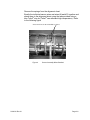
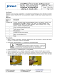
SUPPLEMENT TO
INSTALLATION &
STARTUP MANUAL:
PROCEDURE FOR
ELEVATED
TEMPERATURE SENSOR
HEAD INSTALLATION
CiDRA Corporate Services
Tel. 203-265-0035
50 Barnes Park North
Fax. 203-294-4211
Wallingford, CT 06492
www.cidra.com
Table of Contents
1
2
INTRODUCTION................................................................................................................1-1
SENSOR HEAD INSTALLATION ......................................................................................2-2
2.1
Caution: High Temperatures ......................................................................................2-2
2.2
Tools Required For Installation ..................................................................................2-2
2.3
Sensor Installation......................................................................................................2-3
2.3.1
Sensor Insulator Installation ...............................................................................2-3
2.3.2
Sensor Alignment Sheet Installation...................................................................2-3
2.3.3
Sensor Installation..............................................................................................2-5
2.4
Sensor Cover Installation ...........................................................................................2-7
2.4.1
Cover Seal Installation .......................................................................................2-7
2.4.2
Installing Cover on Pipe .....................................................................................2-9
2.4.3
Cover End Seal Installation ..............................................................................2-12
2.5
Sensor Pre-Amplifier Connections ...........................................................................2-14
2.5.1
Sensor Band to Pre-Amplifier Connection........................................................2-14
2.5.2
Sensor to Transmitter Cable Connection .........................................................2-16
List of Figures
Figure 1
Figure 2
Figure 3
Figure 4
Figure 5
Figure 6
Figure 7
Figure 8
Figure 9
Figure 10
Figure 11
Figure 12
Figure 13
Figure 14
Figure 15
Figure 16
Figure 17
Sensor Polyimide Sheet Installation.......................................................................2-3
Alignment Sheet Attachment to Pipe......................................................................2-4
Installed Sensor Band ............................................................................................2-5
Sensor Assembly Wires Bundled ...........................................................................2-6
Cover Seal Installation ...........................................................................................2-7
Cover Seal Final Installation...................................................................................2-8
Pre-amplifier Mounting Screws ..............................................................................2-9
Remove Fiberglass Insulation ................................................................................2-9
Sensor Cable Feed-Through Assembly .................................................................2-9
Cover Lower Support Ring ...................................................................................2-10
Cover Bolt Tightening Sequence..........................................................................2-11
Measure & Cut End Seal......................................................................................2-12
End Seal Installation.............................................................................................2-12
Cover End Seal Compression Ring......................................................................2-13
Pre-amplifier Housing Feed-through ....................................................................2-14
Pre-amplifier Top and Bottom View......................................................................2-14
Wired and Mounted Pre-amplifier.........................................................................2-15
21020-01Rev 01
Page i
1
INTRODUCTION
This manual is intended to be a supplement to the SONARtrac®
Process Monitoring System Installation & Startup Manuals. The
information contained in this supplement pertains only to the Elevated
Temperature Sensor Head Assembly. The Installation Manual should
be read and understood prior to use of this manual.
The Elevated Temperature Sensor Head is rated for use in General
Purpose (non-hazardous) locations.
All installation guidelines and safety related items listed in the VF-100
or GVF-100 Manual pertain to installation of the Elevated Temperature
Sensor Head.
For additional information, contact your local sales agent or Customer
Support by telephone at 1-877-243-7277 (1-877-CIDRA77) or by EMail at: [email protected]
21020-01 Rev 01
Page 1-1
2
SENSOR HEAD INSTALLATION
2.1
Caution: High Temperatures
Be careful when installing or removing the high temperature system.
Incidental contact with the process pipe may cause serious burns.
The sensor cover and fasteners may become extremely hot.
Always use appropriate gloves and clothing.
WARNING
Potential burn hazard. Always wear appropriate gloves when
installing or removing system from hot pipes.
2.2
Tools Required For Installation
Refer to the VF-100 Installation Manual for a list of tools required for
installation. Additional tools and supplies are listed below
Sensor Materials
Sensor Tools/Supplies
0.005” thick polyimide sheet
9/32” socket or slotted screwdriver
adapter for use with torque wrench
Sensor alignment sheet
Torque wrench with 22 in-lbf capacity
Alignment sheet attachment springs
2 ea ¼” x 20’ roll of 100% expanded
Value Seal Joint Sealant
8 sensors
Cover Materials
®
Tefzel cable tie
Cover Assembly
Wire number tags
Preamplifier Assembly
Sensor alignment sheet springs
Cover Fastener Kit
Table 1
21020-01 Rev 01
Materials & Tools For Elevated Temperature Sensor Head Installation
Page 2-2
2.3
Sensor Installation
2.3.1
Sensor Insulator Installation
Properly clean the process pipe as described in the VF-100 or GVF100 Manual along a 36 inch length of process pipe.
Wrap the polyimide (Kapton) sheet around the pipe such that it is in
the middle of the cleaned section. (The goal is to electrically insulate
the alignment sheet from the pipe.) Temporarily secure the sheet with
tape (if needed) outboard of where the sensors will be located.
36 inches cleaned
Process pipe
Polyamide sheet
Tape outboard of sensor location
Figure 1
2.3.2
Sensor Polyimide Sheet Installation
Sensor Alignment Sheet Installation
WARNING
Use care when handling alignment sheet, sharp edges may
cause cuts.
CAUTION
Use care when handling alignment sheet, do not damage wires
attached to alignment sheet.
Attach alignment sheet to pipe using 4 springs. The seam of
alignment sheet should be aligned such that it will be as close as
possible to the preamplifier housing on the cover when the cover is
installed. It is preferred that the preamplifier housing is oriented “up”
(12 o’clock position) for horizontal pipe installations.
Remove the tape (if used) from the Kapton sheet.
Note: For vertical installations install the cover inner support ring ½inch from the upper edge of the Kapton sheet.
21020-01 Rev 01
Page 2-3
Note: Wires #9 and #10 on the alignment sheet are used for
grounding and temperature.
Alignment
sheet
X
Alignment sheet
retaining springs
X
X
X
X
Kapton sheet
X
X
X
½ inch
Cover inner support ring
(vertical installations)
installed ½-inch from Kapton
Wires #9 & 10 (partial
view)
Important: X refers to sensor installation locations
Figure 2
21020-01 Rev 01
Alignment Sheet Attachment to Pipe
Page 2-4
2.3.3
Sensor Installation
Slightly bend the alignment tabs on the sensor band alignment sheet
upward. These will serve to align the sensors during installation.
Wrap the sensor bands around the alignment sheet. Align the edge of
the sensor band with the alignment tabs on the alignment sheet.
IMPORTANT: The alignment tabs on the alignment sheet are not
symmetrical. Install the sensors on the side of the tab shown in
Figure 2 above.
Install the sensors so the cable exiting from under the sensor clamp
does not touch the alignment tabs (this may cause the sensor element
to be cut and cause a short).
Install the sensor such that their connectors are opposite the direction
of wires #9 & 10 on the alignment sheet
Orient the sensor band attachment bolts with the top of the pipe
(horizontal installation) so they will be directly under the cover
assembly.
Tighten the screw on each of the sensor bands to 20 – 22 in-lbf using
a torque wrench with a 9/32” socket or slotted screwdriver adapter.
Wait 10 minutes. Re-torque the band screws to 20-22 in-lbf.
If the sensors have not been previously numbered, label each of the
leads from the sensors with wire numbers. Apply the tag near the
connector end of the wire. Label the first sensor, with respect to flow
direction, with #1 tag; label the second sensor with tag #2, etc..
Figure 3
21020-01 Rev 01
Installed Sensor Band
Page 2-5
Remove the springs from the alignment sheet
Bundle the individual sensor wires and wires #9 and #10 together and
attach them to the alignment sheet using the tabs provided using a
blue Tefzel® wire tie (Tefzel® can withstand high temperature). Refer
to the following figure
Sensor and wires #9 & 10 bundled at 2 places
Figure 4
21020-01 Rev 01
Sensor Assembly Wires Bundled
Page 2-6
2.4
Sensor Cover Installation
2.4.1
Cover Seal Installation
Note: The seals to be installed on each cover half must seal on each
other when the cover halves are assembled. Also, the crossing seals
(start and stop ends) must be on opposite sides of the cover when
installed.
Remove a short length of the adhesive backing covering on the joint
seal strip to expose the adhesive. Apply the joint seal strip starting at
a middle of either the top or bottom cover half such that it curves
partially around the inside of a bolt hole on the flange. Continue to
install the seal material on the flange so that it runs just inside the
inner edge of the flange bolt holes. At the last hole on the flange side
(see picture) install the seal in a straight line toward the face seal.
Wrap around the end of the flange face and install the seal along the
outer edge of the face seal. Continue installing seal around cover
flanges and end seals. Cross the starting end of the seal with the end
point as shown in the figure below.
Start adhering seal by
wrapping around middle
hole in the flange
Turn at tangency
point of bolt hole
Seal installed on outer
edge of face seal
End of seal
Start of seal
Figure 5
21020-01 Rev 01
Cover Seal Installation
Page 2-7
Repeat the seal installation on the opposite cover half. Note: Ensure
the seals are installed to mirror each other as they must seal on each
other during cover installation. Also, the crossing seals must be on
opposite sides of the covers when they are installed. Seals must be
one continuous length on each cover half.
Crossing seals must be on
opposite sides when cover
halves are installed
Cover Top
Figure 6
21020-01 Rev 01
Cover Bottom
Cover Seal Final Installation
Page 2-8
2.4.2
Installing Cover on Pipe
Remove the pre-amplifier housing cover from the upper cover
assembly. Disconnect external connector cable assembly from preamplifier assembly. Remove the four screws holding the pre-amplifier
assembly in place. Remove the pre-amplifier and place it in a secure
location so it will not be damaged.
Pre-amplifier
mounting screw(s)
(lower screw
removed)
Figure 7
Pre-amplifier Mounting Screws
Carefully remove the fiberglass insulation from the pre-amplifier
housing by grasping it along the edge and pull it upward. Place it in a
secure location to keep it from being damaged.
Figure 8
Remove Fiberglass Insulation
Remove the sensor cable feed-through from the pre-amplifier housing
Figure 9
21020-01 Rev 01
Sensor Cable Feed-Through Assembly
Page 2-9
For horizontal pipe installations, install the cover half with the
preamplifier box over the sensor band such that it is centered on the
band and over the sensor band cables (allows for maximum sensor
cable length). Ensure the cables are accessible.
Install the lower cover half and temporarily clamp the upper and lower
cover halves in place using spring clamps (or equivalent). Important:
Do not allow the cover end seals to touch any part of the sensor array
including the polyamide insulation. The seals (and seal rings to be
installed in the following steps) should only be in contact with the
process pipe.
For vertical pipe installations hang the cover halves from the cover
support ring. Temporarily install the cover lower support ring on the
bottom of the cover assembly.
Figure 10
Cover Lower Support Ring
Install the lower cover half and temporarily clamp the upper and lower
cover halves in place using spring clamps (or equivalent). Important:
Do not allow the cover end seals to touch any part of the sensor array
including the polyamide insulation. The seals (and seal rings to be
installed in the following steps) should only be in contact with the
process pipe.
21020-01 Rev 01
Page 2-10
Install 5/16”–18 cover bolts fitted with a washer and lock washer in
each cover bolt hole numbered 1 – 16 in the following figure. Tighten
the bolts gradually per the tightening sequence given in the following
figure so that the flanges remain essentially parallel. Bring halves
together evenly until most or the entire gap is removed. Maximum
allowable gap is 0.10”.
Install ¼”-20 bolts with nuts, washers and lock washers in holes
numbered 17 – 20.
11
15
1
3
5
9
13
19
17
20
18
14
10
Figure 11
21020-01 Rev 01
7
6
2
4
8
12
16
Cover Bolt Tightening Sequence
Page 2-11
2.4.3
Cover End Seal Installation
Un-spool a length of adhesive backed seal and wrap it around the
pipe. Overlap the length of seal by about 1.5 inches and then cut it.
Repeat for the opposite end of the cover.
Figure 12
Measure & Cut End Seal
Peel the backing on the seal strip to expose the adhesive strip.
Start installing the sealant about ½-inches before the center bolt hole
on the top of the cover. Push the seal into the space between the
cover and the pipe using an Allen wrench (or similar tool) so the
adhesive on the seal will stick to the seal material that was preinstalled on the cover (reference Figure 6). Continue to push the seal
in until it is fully seated. The end of the seal should overlap the start
point of the seal by about 1 inch (or extend beyond the center bolt
hole by about ½ inch.
Center bolt hole on
cover end
Seal end point about ½
inches from hole
Figure 13
21020-01 Rev 01
End Seal Installation
Page 2-12
Repeat this installation procedure on the opposite end of the cover.
Install the cover end seal compression rings so that they overlap the
cover flange seam. The double pair of bolt holes in the end seal
compression rings will align with the corresponding double threaded
holes in the cover halves.
NOTE: If the end seal compression rings do not have a double pair o
bolt holes as shown, align the end seam of the compression rings
between the two closely spaced tapped holes on the end of the cover.
Cover flange seam
Note overlap of
compression ring with
respect to cover flange
Figure 14
Cover End Seal Compression Ring
Install 5/16-18 bolts fitted with a washer and lock washer in each
cover end seal compression ring bolt hole. Tighten the bolts gradually
so that the rings pull in gradually and evenly with respect to the cover.
The final gap between the compression ring and the cover should be
less than 1/8 inch around the circumference. Note: It might be
necessary to start the seal ring bolts without the washers due to the
length of the bolts. Once the seal has compressed, remove the bolts
and install the flat and lock washer.
21020-01 Rev 01
Page 2-13
2.5
Sensor Pre-Amplifier Connections
2.5.1
Sensor Band to Pre-Amplifier Connection
Carefully feed the eight sensor wires and wires #9 and #10 from the
sensor band through the slot in the sensor band feed through.
Reinstall the feed-through in the pre-amplifier housing.
Figure 15
Pre-amplifier Housing Feed-through
Reinstall the fiberglass insulation in the pre-amplifier housing and
route the sensor band wires on top of the insulation.
Lay the pre-amplifier in the pre-amplifier housing with the bottom side
facing up.
Sensor shorting plug (may be
mounted in alternate position)
Pre-amplifier top side
Figure 16
21020-01 Rev 01
Pre-amplifier bottom side
Pre-amplifier Top and Bottom View
Page 2-14
WARNING
Discharge each sensor per user manual instructions just prior to
connecting sensors to preamp. Failure to do so may result in
damage to preamp!!
Starting with sensor #1, discharge that sensor by attaching it to the
sensor shorting plug. Insert the sensor connector into the mating
connector (connector #1) mounted on the bottom of the preamplifier
module. Repeat for the remaining 9 wires. Note: It may be easier to
connect the sensors by first removing the connector block and then reinstalling the block after all connections have been made.
Turn the pre-amplifier over.
Re-install the four pre-amplifier mounting screws.
Connect the wire interconnect wire connector to the pre-amplifier.
Interconnect
wire connector
Figure 17
Wired and Mounted Pre-amplifier
Ensure the grounding wire is attached to the pre-amplifier cover
Install the preamplifier cover and install the four cover screws.
21020-01 Rev 01
Page 2-15
2.5.2
Sensor to Transmitter Cable Connection
Install the sensor cover to transmitter cable connector.
Terminate the individual sensor to transmitter cable conductors in the
transmitter per the Installation Manual.
This completes installation of the high temperature sensor head.
Refer to the SONARtracTM VF-100 user manual for transmitter
installation and start-up instructions.
21020-01 Rev 01
Page 2-16
CiDRA Corporate Services
50 Barnes Park North
Wallingford, CT 06492
(In U.S.): 877-cidra77
Tel: 203-265-0035
Fax: 203-294-4211
Visit CiDRA Online at: www.cidra.com
CiDRA Corporate Services
Tel. 203-265-0035
50 Barnes Park North
Fax. 203-294-4211
Wallingford, CT 06492
www.cidra.com