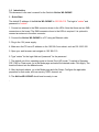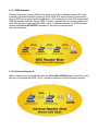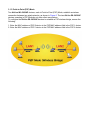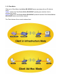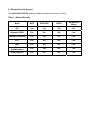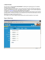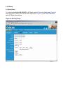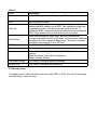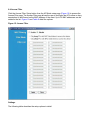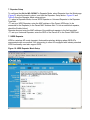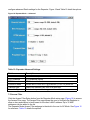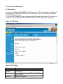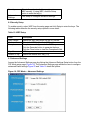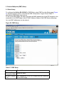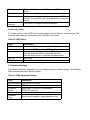
1
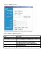
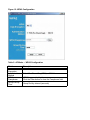
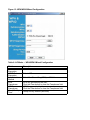
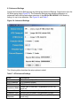
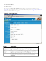
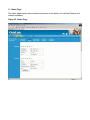
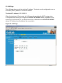
AirLive WL-5430AP
Wireless Access Point
User’s Guide
1.0 Introduction
This document is the user’s manual for the OvisLink AirLive WL-5430AP.
1. Quick Start
The default IP address of the AirLive WL-5430AP is 192.168.0.10. The login is “admin” and
password is “ovislink”.
1. Connect an antenna to the SMA connector closer to the LEDs. Note that there are two SMA
connectors on the board. The SMA connector closer to the LEDs is required. It is optional to
connect an antenna to the other connector
2. Connect the AirLive WL-5430AP to a PC using an Ethernet cable.
3. Plug in the 12V power supply.
4. Make sure the PC has a IP address on the 192.168.0.xxx subnet, such as 192.168.0.100.
5. Open your web browser and navigate to 192.168.0.10.
6. Type “admin” for the login field and “password” for the password.
7. The default out-of-box operating mode is Access Point (AP) mode. To switch to Repeater,
P2P, PMP or Client mode, go to the Mode page and select the desired mode. Click Apply. The
board will reboot into the desired mode.
8. After the board reboots, go to the Mode page and click Setup. Configure the applicable
properties for that mode, such as security, SSID, channel, etc.
9. The AirLive WL-5430AP should now be ready to use.
`
3. Operating Modes
This section provides an overview of the All-into-1 operating mode.
3.1 Introduction to Operating Modes
3.1.1 Traveler’s AP Mode
By default, the out-of-box operational mode is Access Point (AP) Mode (or Traveler’s AP
Mode). When the system is reset to the default manufacturing settings, the operating mode
reverts to AP Mode. In AP Mode, the system functions as a standard AP, where wireless
clients connected to the AP can then connect to other wireless clients or to the wired network.
For example, when traveling to a hotel that has high-speed internet access, the user can
connect to the Internet through the AP which is connected to an Ethernet cable in the room
(see Figure 1).
The AirLive WL-5430AP acts only as a ISO Layer 2 bridge and does not act as a DHCP
server. Therefore, it does not supply dynamic IP addresses and relies instead on the network
to supply them.
3.1.2 Repeater Mode
A repeater is placed between an AP and a client to extend the distance between the two
WLAN devices.Functioning as a repeater, the AirLive WL-5430AP connects to both a client
card as an AP and to another AP. Two repeater modes are available in the All-into-1:
• WDS Repeater:
WDS Repeaters connect as APs to other APs using the WDS link and MAC address to
identify one another.
• Universal Repeater:
Universal Repeaters connect as child clients to parent APs using the SSID to connect.
Figure 2 shows an example of a Repeater network with two AirLive WL-5430AP Repeaters
connected to a AirLive WL-5430AP, with each Repeater allowing wireless clients to
associate.
3.1.2.1 WDS Repeaters
Wireless Distribution System (WDS) functionality is an industry standard wireless AP mode
(repeater) that enables wireless bridging in which WDS APs communicate with one another
using a WDS link. In typical repeater applications, APs connecting to other APs equipped with
WDS functionality must also support WDS. Typically, repeaters will not function properly with
other APs that are not equipped with WDS. Figure 3 shows an example of a WDS Repeater
network with AirLive WL-5430AP Repeaters in Parent/Child configurations
with other Repeaters.
3.1.2.2 Universal Repeaters
When configured as a Universal Repeater, the AirLive WL-5430AP allows connectivity to APs
that are not equipped with WDS. Figure 4 shows an example of a WDS Repeater network.
3.1.3 Point-to-Point (P2P) Mode
Two AirLive WL-5430AP devices, each in Point-to-Point (P2P) Mode, establish a wireless
connection between two wired networks, as shown in Figure 5. The two AirLive WL-5430AP
devices operating in P2P Mode do not allow client associations.
To configure the AirLive WL-5430AP devices to establish a P2P wireless bridge, ensure the
following:
1. Enter the MAC address of P2P-2 device in the P2P MAC address field in the P2P-1 device.
2. Enter the MAC address of P2P-1 device in the P2P MAC address field in the P2P-2 device.
3.1.4 Point-to-Multipoint (PMP) Mode
An AirLive WL-5430AP device operating in Point-to-Multipoint (PMP) Mode wirelessly
connects two or more wired networks, as shown in Figure 6. The root AirLive WL-5430AP
device (LAN1) operates in PMP Mode, while the other AirLive WL-5430AP devices (LAN2,
LAN3) must operate in P2P Mode.
When operating in PMP Mode, the AirLive WL-5430AP device does not allow client
associations.
The user must enter the MAC addresses (up to six) of each P2P device into the PMP system
table of Remote AP MAC addresses.
3.1.5 Client Mode
When set to Client Mode, the AirLive WL-5430AP device associates with an AP within its
range.
Figure 7 shows the Client Mode AirLive WL-5430AP operating as a wireless client in
infrastructure mode.
Figure 8 shows the Client Mode AirLive WL-5430AP joined with another Client Mode AirLive
WL-5430AP device in an Ad-Hoc network.
The Client behaves like a normal wireless client.
4. Wireless Security Support
The AirLive WL-5430AP supports wireless encryption as shown in Table1.
Table 1: Wireless Security
Mode
WEP
WPA-PSK
WPA2
WPA/WPA2
Mixed
AP
Yes
Yes
Yes
Yes
Repeater (WDS)
Yes
No
No
No
Repeater (Universal)
Yes
Yes
No
No
P2P
Yes
No
No
No
PMP
Yes
No
No
No
Client
(Infrastructure)
Yes
Yes
No
No
Client (Ad-Hoc)
Yes
No
No
No
5. Mode Selection
The first step in using the AirLive WL-5430AP is selecting the operating mode. The default
operating mode is AP Mode.
To view the web page for the device, open a web browser and enter 192.168.0.10 (default IP
address of the device) as the URL. The default username is “admin” and the default password
is “password.” Figure 9 shows the page displayed once logged in.
To select a mode, click the Mode tab. Click the radio button next to the desired mode and click
the Apply button. The device will reboot in the selected mode. After the board reboots, click the
Setup button to begin configuring the device.
The “What’s This?” button opens a popup window with a brief description of each mode.
Figure 9: Mode Page
6. AP Setup
6.1 Basic Setup
To configure the AirLive WL-5430AP in AP Mode, select AP from the Mode page (Figure 9),
allow the board to reboot, and click the AP: Setup button. Figure 10 and Table 2 show the
basic AP Mode setup options.
Figure 10:AP Setup Page
Table 2:
Field
Description
Mode
Selects 802.11g/b mode: 802.11g only, 802.11b only, or Mixed
SSID
Wireless Network Name
When AutoLink is enabled, the configuration utility automatically
patches the MAC Address to the SSID. This enables the client card
to generate a profile of the AP connected to with AutoLink. To
change the SSID, uncheck the AutoLink radio button and change the
SSID. Then, recheck the AutoLink radio button to continue.
When used with Marvell client cards, Boost Mode enhances
throughput an additional 30% at 54 Mbps, and extends the additional
throughput at 2x the original 54 Mbps range. The result is a relative
throughput improvement of up to 300 feet.
Enable/disable the SSID broadcast feature.
AutoLink
Boost Mode
SSID Broadcast
Channel
Security
Advanced Settings
Selects the channel
Select Disable, WEP, WPA, WPA2, WPA/WPA2 Mixed mode
security.
Select the option, and click the Setup button.
Default: Disable Security.
Click Setup to configure advanced settings.
Access Filter
Click Setup to configure the access filter
6.2 Security Setup
To enable security, select the desired security mode (WEP or WPA) from the AP setup page
and click Setup to enter the keys.
Figure 11: WEP Configuration
The following tables describe the security setup options in more detail.
Table 3: AP Mode — WEP Configuration
Field
Authentication Type
WEP Length
Mode
Passphrase
Key 1-4
Default Tx key
Description
Choose Open or Shared Key
Select WEP encryption key length: 64 bits or 128 bits.
Selects the WEP key format, ASCII or Hex
Passphrase used to generate the WEP keys.
Click the Generate button to generate the keys.
Click the Clear button to clear the Passphrase field.
WEP keys. Entered in the format specified by the WEP
Length and Mode fields.
Select default WEP key from Keys 1-4.
Figure 11: WPA Configuration
Table 4: AP Mode — WPA Configuration
Field
WPA Data
Encryption
Authentication
Method
WPA
Passphrase
Group Re-Key
Time
Description
Select AES or TKIP.
Select Pre-Shared Key (PSK) or 802.1X.
WPA key provided by the user.
Click the Clear button to clear the Passphrase field
Group Re-Key interval (seconds)
Figure 12: WPA2 Configuration
Table 5: AP Mode — WPA2 Configuration
Field
WPA2 Data
Encryption
Authentication
Method
WPA2
Passphrase
Group Re-Key
Time
Description
Select AES.
Select Pre-Shared Key (PSK) or 802.1X.
WPA2 key provided by the user.
Click the Clear button to clear the Passphrase field
Group Re-Key interval (seconds)
Figure 13: WPA/WPA2 Mixed Configuration
Table 6: AP Mode — WPA/WPA2 Mixed Configuration
Field
WPA Data
Encryption
WPA2 Data
Encryption
Authentication
Method
WPA
Passphrase
WPA2
Passphrase
Group Re-Key
Time
Description
Select AES or TKIP.
Select AES.
Select Pre-Shared Key (PSK) or 802.1X.
WPA key provided by the user.
Click the Clear button to clear the Passphrase field
WPA2 key provided by the user.
Click the Clear button to clear the Passphrase field
Group Re-Key interval (seconds)
6.3 Advanced Settings
Access the Advanced Settings page by clicking the Advanced Settings: Setup button from the
AP Mode setup page (Figure 10). The Advanced Settings page allows configuration of
advanced Radio settings and range extension of the AirLive WL-5430AP in AP Mode by
linking it to up to two repeaters. See Figure 14 and Table 7.
Figure 14: Advanced Settings
The following table describes the setup options in detail.
Table 7: AP Advanced Settings
Field
Beacon Interval
RTS Threshold
DTIM Interval
Protection Mode
Transmit Rate
Preamble Type
Connect
Repeater
Description
Beacon interval (in milliseconds)
RTS threshold (Bytes)
DTIM interval
Allows user to force 802.11g protection (RTS/CTS)
mode off.
Selects the transmit rate: Auto or a fixed rate
Selects short preamble, long preamble, or Auto
Enable/Disable the use of a Repeater (WDS Repeater
mode only).
Repeater MAC
Address
MAC address for each Repeater. Up to two Repeaters
may be connected.
6.3.1 Connect Repeater
Up to two Repeaters may be connected. If a Repeater is used with the AP:
1. Go to the Advanced Settings page.
2. Select Enable for the “Connect Repeater” field.
3. Enter the MAC address for each Repeater in the “Repeater MAC Address” field.
6.4 Access Filter
Click the Access Filter: Setup button from the AP Mode setup page (Figure 10) to access the
Access Filter page. The Access Filter page allows the user to configure the AP to allow or deny
association to itself based on the MAC address of the client. Up to 32 MAC addresses can be
added to the list. Figure 15 and Table 8 detail the options.
Figure 15: Access Filter
Settings
The following table describes the setup options in detail.
Table 8: AP Access Filter Settings
Field
Description
MAC filtering
Enables/Disables MAC filtering mode
Filter Mode
Provides the option to allow or deny clients with MAC
addresses listed
Filter List
Up to 32 MAC addresses can be listed.
MAC addresses
List of MAC addresses to filter
7. Repeater Setup
To configure the AirLive WL-5430AP in Repeater Mode, select Repeater from the Mode page
(Figure 9), allow the board to reboot, and click the Repeater: Setup button. Figure 16 and
Table 9 show the Repeater Mode setup options.
• To select a Repeater Mode, choose WDS Repeater or Universal Repeater in the Repeater
Type field.
• To set up a WDS Repeater, enter the MAC address of the Parent AP/Router (to be
connected to the Repeater) in the Parent MAC Address field. To link an additional repeater,
check the Enable Linked
Repeater box and enter the MAC address of the additional repeater in the field provided.
• To set up a Universal Repeater, enter the SSID of the Parent AP in the Parent SSID field.
7.1 WDS Repeater
WDS is a wireless AP mode (repeater) that enables wireless bridging where WDS APs
communicate with one another. APs connecting to other APs equipped with industry standard
WDS functionality must also support WDS.
Figure 16: WDS Repeater Mode Setup
7.2 Universal Repeater
Universal Repeaters allow connectivity to APs that are not equipped with WDS.
Figure 17: Universal Repeater Mode Setup
Table 9: Repeater Setup
Field
Description
Repeater Type
Select WDS Repeater or Universal Repeater.
Parent SSID
Wireless Network Name of parent Repeater.
NOTE: Only applies to Universal Repeater mode.
Channel
Selects the channel
Parent MAC Address MAC address of Parent AP/Router to which this Repeater is
connected.
NOTE: Only applies to WDS Repeater mode.
Mode
Selects 802.11g/b mode: 802.11g only, 802.11b only, or Mixed
SSID
Wireless Network Name.
Enable/disable the AutoLink feature.
When AutoLink is enabled, the configuration utility automatically
patches the MAC Address to the SSID. This enables the client card
to generate a profile of the AP connected to with AutoLink. To
change the SSID, uncheck the AutoLink radio button and change
the SSID. Then, recheck the AutoLink radio button to continue.
Enable/disable the SSID broadcast feature.
Select Disable, WEP, or WPA security.
Select the option, and click the Setup button to enter the key(s) for
WEP or WPA.
Click Setup to configure advanced settings.
Click Setup to configure the access filter
AutoLink
Broadcast SSID
Security
Advanced Settings
Access Filter
7.3 Security Setup
To enable security, select the desired security mode (WEP or WPA) from the Repeater Mode
setup page (Figure 16) and click the Setup button to enter the keys. The following tables
describe the security setup options in more detail.
Table 10: WEP Setup
Field
Description
WEP Length
Mode
Passphrase
Selects the WEP key length: 64 bits or 128 bits.
Selects the WEP key format, ASCII or Hex
Passphrase used to generate the WEP keys.
Click the Generate button to generate the keys.
Click the Clear button to clear the Passphrase field.
WEP keys
Selects the default WEP key (1-4)
Key 1-4
Default Tx key
Table 11: WPA Setup
Field
Description
Authentication
Method
Passphrase
Group Re-Key
Time
Select PSK mode
WPA key
Group Re-Key interval (seconds)
7.4 Advanced Settings
Access the Advanced Settings page by clicking the Advanced Settings: Setup button from the
Repeater Mode setup page (Figure 16). The Advanced Settings page allows the user to
configure advanced Radio settings for the Repeater. Figure 18 and Table 12 detail the options.
Figure 18: Repeater Mode — Advanced
Table 12: Repeater Advanced Settings
Field
Description
Beacon Interval
RTS Threshold
DTIM Interval
Protection Mode
Transmit Rate
Preamble Type
Beacon interval (in milliseconds)
RTS threshold (Bytes)
DTIM interval
Allows user to force 802.11g protection (RTS/CTS) mode off.
Selects the transmit rate: Auto or a fixed rate
Selects short preamble, long preamble or Auto
7.5 Access Filter
Click the Access Filter:Setup button from the Repeater Mode setup page (Figure 16) to access
the Access Filter page. The Access Filter page allows the user to configure the Repeater to
allow or deny association to itself based on the client’s MAC address. Up to 32 MAC
addresses can be added to the list.
The Repeater Mode Access Filter webpage is identical to the one for AP Mode. See Figure 15
for reference. Table 13 details the options.
Table 13: Repeater Access Filter Settings
Field
MAC filtering
Filter Mode
Filter List
Description
Enables/Disables MAC filtering mode
Provides the option either to allow or deny clients with
the MAC addresses listed.
Up to 32 MAC addresses can be listed.
MAC addresses
List of MAC addresses to filter
8. Point-to-Point (P2P) Setup
8.1 Basic Setup
To configure the AirLive WL-5430AP in P2P Mode, select P2P from the Mode page (Figure 9),
allow the board to reboot, and click the P2P: Setup button. Figure 19 and Table 14 describe
the P2P Mode setup options.
To set up the P2P bridge, the user must enter the MAC address of the other P2P bridge to be
connected to this P2P bridge in the AP MAC Address field of the P2P Mode setup page.
Figure 19: P2P Setup
Table 14: P2P Setup
Field
Description
AP MAC
Address
Mode
MAC address of the P2P bridge that this bridge is
connected to
Selects 802.11g/b mode: 802.11g only, 802.11b
only, or Mixed
Selects the channel
Channel
Security
Advanced
Settings
Selects the option to disable security or to use
WEP security. If using WEP, click the Setup
button to enter the key(s).
Click Setup to configure advanced settings.
8.2 Security Setup
To enable security, select WEP from the setup page and click Setup to enter the keys. The
following tables describe the security setup options in more detail.
Table 15: WEP Setup
Field
Description
WEP Length
Mode
Passphrase
Selects the WEP key length: 64 bits or 128 bits.
Selects the WEP key format, ASCII or Hex
Passphrase used to generate the WEP keys.
Click the Generate button to generate the keys.
Click the Clear button to clear the Passphrase field.
WEP keys
Selects the default WEP key (1-4)
Key 1-4
Default Tx key
8.3 Advanced Settings
Access the Advanced Settings page by clicking the Advanced Settings:Setup button from the
P2P Mode setup page (Figure 19). The Advanced Settings page allows the user to configure
advanced Radio settings.Figure 20 and Table 16 detail the options.
Figure 19: P2P Mode— Advanced Settings
Table 16: P2P Advanced Settings
Field
Description
RTS Threshold
DTIM Interval
Protection Mode
Transmit Rate
Preamble Type
RTS threshold (Bytes)
DTIM interval
Allows user to force 802.11g protection (RTS/CTS) mode off.
Selects the transmit rate: Auto or a fixed rate
Selects short preamble, long preamble or Auto
9. Point-to-Multipoint (PMP) Setup
9.1 Basic Setup
To configure the AirLive WL-5430AP in PMP Mode, select PMP from the Mode page (Figure
9), allow the board to reboot, and click the PMP: Setup button. Figure 20 and Table 17
describe the PMP Mode setup options.
To set up the PMP bridge, the user must enter the MAC address(es) of the P2P bridge(s) to be
connected to this PMP bridge in the AP MAC Address field(s) of the PMP Mode setup page.
Up to six MAC addresses can be entered.
Figure 20: PMP Setup
Table 17: PMP Setup
Field
Remote AP
Connection Mode
AP MAC Address
(1-6)
Description
Default is Static.
MAC address(es) of the P2P bridges that are connected
to this PMP bridge
Mode
Channel
Security
Selects 802.11g/b mode: 802.11g only, 802.11b only, or
Mixed
Selects the channel
Selects the option to disable security or to use WEP
security. If using WEP, click the Setup button to enter the
key(s).
Advanced
Settings
Click Setup to configure advanced settings.
9.2 Security Setup
To enable security, select WEP from the setup page and click Setup to enter the keys. The
following tables describe the security setup options in more detail.
Table 18: WEP Setup
Field
Description
WEP Length
Mode
Passphrase
Selects the WEP key length: 64 bits or 128 bits.
Selects the WEP key format, ASCII or Hex
Passphrase used to generate the WEP keys.
Click the Generate button to generate the keys.
Click the Clear button to clear the Passphrase field.
WEP keys
Selects the default WEP key (1-4)
Key 1-4
Default Tx key
9.3 Advanced Settings
The Advanced Settings page allows you to configure advanced Radio settings. The following
table describes the setup options in detail.
Table 19: PMP Advanced Settings
Field
Description
RTS Threshold
DTIM Interval
Protection
Mode
Transmit Rate
Preamble
Type
RTS threshold (in bytes)
DTIM interval
Allows user to force 802.11g protection
(RTS/CTS) mode off.
Selects the transmit rate: Auto or a fixed rate
Selects short preamble, long preamble or Auto
10. Client Mode Setup
10.1 Basic Setup
To configure the AirLive WL-5430AP in Client Mode, select Client from the Mode page
(Figure 9), allow the board to reboot, and click the Client: Setup button. Figure 21 and Table 20
describe the Client Mode setup options.
Figure 21: Client Bridge Setup
Table 20: AP Setup
Field
Description
Station Mode
Selects 802.11g/b mode: 802.11b only or 802.11g/b
MAC Cloning
Mode
Enable MAC Cloning Mode. This clones all the MAC addresses of
devices connected to the Ethernet (wired) port to a single MAC
address sent out wirelessly to an AP or Repeater
Wireless Network Name. You can enter it directly in this field or
click the Site Survey button to select from a list of available
networks.
SSID
Table 20: AP Setup (Continued)
Field
Operation Mode
Channel
Security
Preamble Type
Transmit Rate
Description
Selects Ad-Hoc or Infrastructure mode
Selects the channel (Ad-Hoc network only)
Selects the option to disable security or to use WEP or WPA
security. If using WEP or WPA, click the Setup button to enter
the key(s).
Selects short or long preamble
Selects the transmit rate: a fixed rate or Auto
10.2 MAC Cloning
To enable MAC cloning mode, go to the MAC Cloning field on the LAN page and select
Enabled. MAC cloning clones all the MAC addresses of the devices connected to the Ethernet
(wired) port to a single MAC address sent out wirelessly to an AP or Repeater.
10.3 Client Mode — Site Survey
Clicking the Site Survey button brings up the Site Survey page, which displays the available
Access Points and Ad-Hoc networks in the neighborhood. The user then selects the AP or
Ad-Hoc network to join. Figure 22 and Table 21 describe the options.
Figure 22: Client Mode — Site Survey
Table 21: Client Mode — Site Survey
Field
SiteSurvey table
Scan
Join
Close
Description
Lists the available Access Points and Ad-Hoc networks.
To select a wireless network to join, click its radio button.
Start the Site Survey Scan process.
Select a wireless network.
Click the Join button to associate the client bridge with the
selected AP/node or Ad-Hoc network.
Close the Site Survey page.
11. Status Page
The status page reports relevant status information for the device, for both the Ethernet and
wireless interfaces.
Figure 22: Status Page
12. Admin Page
The admin page lets you upgrade the device’s firmware or change the password.
Figure 23: Admin Pag
12.1 Firmware Upgrade
To upgrade the firmware, click the Browse button and select the image file. Click Apply to
upgrade.
12.2 Update Password
To change the password, enter the new password in the New Password and Reconfirm
Password fields and click Apply.
13. LAN Page
The LAN page lets you set the device’s IP address. The device can be configured to use an
automatic (DHCP) address or a fixed IP address.
The default IP address is 192.168.0.10.
When the device is in Client mode, the LAN page also provides the MAC cloning option.
It is important that before you configure the AirLive WL-5430AP device (regardless of the
mode it is in) to Automatic IP, you should know how to determine the AirLive WL-5430AP
device’s IP address from the device it is connected to.
Figure 24: LAN Page