1
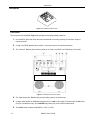
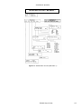
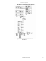
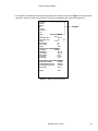
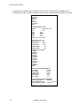
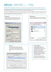
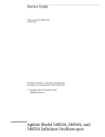
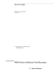
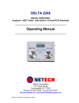
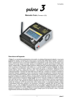
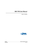
User Manual DA-2000 Defibrillator Analyzer Notices © Copyright 2000 BC Group International Inc. 3081 Elm Point Industrial Dr St. Charles, MO 63301 USA Phone: Toll-Free: Fax: 314-638-3800 888-223-6763 314-638-3200 E-mail: Internet: [email protected] www.bcgroupintl.com All Rights Reserved This publication is protected by copyright and all rights are reserved. No part of this manual may be reproduced or transmitted in any form, or by any means electronic or mechanical, including photocopying and recording, for any purpose other than the purchaser's personal use without the written permission of the product manufacturer. Restrictions and Liabilities Information in this document is subject to change, and does not represent a commitment by BC Group International Inc. (BC Group). Changes made to the information in this document will be incorporated in new editions of the publication. No responsibility is assumed by BC Group for the use or reliability of software or equipment that is not supplied by BC Group. Trademarks BC Biomedical and DA2000 are trademarks of BC Group International Inc. Notices / Contents Contents Section 1 Introduction Description Front Panel Back Panel Specifications Accessories Section 2 Installation & Operation Operation Warnings Getting Acquainted Measuring Defibrillator Energy Defib Pulse Playback Oscilloscope Viewing of Output Measuring Synchronization Generating Waveforms Procedure Testing High Level Out Measuring Peak Voltage, Current & Overshoot Charge Time (DA2000W, P) Pacer (Non-Invasive) Testing Pacer Refractory Period Testing Autosequencing (DA2000P) Programming an Automatic Test Sequence Running an Automatic Test Sequence Resetting the DA2000 for Factory Defaults Section 3 Data Transfer & Utilities Serial Port BC Biomedical Serial Cable (optional accessory) Printing The Utilities Menu Adjusting RS232 Parameters Adjusting Display Contrast Computer Control Commands Communications Protocol Initializing Computer Control Section 4 Troubleshooting & Service Warranty Storage and Shipping Troubleshooting Returning the DA2000 for Service ii 1-1 1-2 1-2 1-3 1-4 1-8 2-1 2-1 2-2 2-7 2-8 2-8 2-9 2-11 2-11 2-12 2-12 2-13 2-14 2-15 2-16 2-17 2-19 2-19 3-1 3-1 3-2 3-2 3-5 3-5 3-6 3-6 3-6 3-6 4-1 4-1 4-1 4-2 4-2 DA2000 User's Guide – Rev. 7/03 Introduction Section 1 Regular testing of defibrillators and pacemakers is critical in order to ensure safe and effective operation. The BC Biomedical DA2000 Defibrillator Analyzer accurately verifies the output characteristics of all defibrillators as well as testing the parameters of non-invasive pacemakers. The DA2000 is battery operated and completely portable. Simple-to-use menu soft keys allow quick access to tests. The DA2000 measures the delivered energy in Joules (watt-seconds) from a defibrillator by simulating the human body’s resistance. The analyzer then measures the flow of current through that resistance. The standard resistance used by the DA2000 is 50 ohms. Defibrillator energy is measured in one of two ranges: 0-100 Joules, or 0-1000 Joules. The defibrillator pulse waveform can be replayed via the ECG jacks or paddle plates for viewing on a recorder, or on an oscilloscope for greater detail. Synchronization time in milliseconds is measured by timing the firing delay from either the Q-wave (base) or Rwave (peak) simulated by the DA2000. The simulated waveform is present at both the ECG jacks and the paddle plates. Peak voltage and peak current (amps) of the defibrillator pulse can be measured. Overshoot voltage and current measurements of the defibrillator pulse are calculated and displayed. The DA2000 also measures the defibrillator’s charge time (the time it takes for a defibrillator to reach its maximum charge setting). Waveforms, including ECG, arrhythmias, and performance, help verify monitor and recorder accuracy, and also test the automatic defibrillator’s ability to recognize and fire. All waveforms are present at the ECG jacks, the paddle plates and scope output. Utilities allow the setting of Serial RS-232 communication parameters to download results to printer, or computer. Display contrast can be adjusted to obtain the best view of the LCD display. Upgrading the DA2000 A number of pre-configured DA2000 models are available. In addition, older models may be upgraded by contacting BC Biomedical. The following DA2000 models are available: • DA2000: RS-232. • DA2000W: “Waveform” version. Features output energy, sync time, peak measurements, overshoot, bidirectional RS-232, waveforms, charge time measurements, 28 programmable autosequences. • DA2000P: “Pacer” version. Output energy, sync time, peak measurements, overshoot, bi-directional RS232, waveforms, charge time measurements, 28 programmable autosequences, pacer output measurements and pacer refractory period measurements. Base unit. Features output energy, synchronization time, peak measurements, bi-directional DA2000 User's Guide 1-1 Introduction Description Figure 1.1. DA2000 Isometric View Front Panel The front panel of the DA2000 (Figure 1.2) includes the following operating features: 1. Universal ECG jacks that utilize AHA and International color coding, allowing for waveform output to monitor/recorder. 2. A “High Level ECG” Banana jack provides 1 Volt peak output of the selected waveform. 3. The “Common” Banana jack provides ground for the “High Level ECG” and “Defib Scope Out” jacks. Figure 1.2. DA2000 Front Panel Layout 4. The “Defib Scope Out” Banana jack provides pulse output to an oscilloscope. 5. A range switch allows for defibrillator settings from 0 to 1000 Joules (high), for power below 0-100 Joules (low) for increased accuracy, and a PACER range setting for pacer output measurements. 6. The Power switch enables the DA2000 (I = ON, O = OFF). 1-2 DA2000 User's Guide Introduction 7. LCD display: 24 characters x 2 lines. The upper line of the LCD display provides messages and test results, while the bottom line displays menu choices. 8. Five “soft keys” can be used to select the desired function highlighted on the lower line of the display. 9. Two nickel-plated Defibrillator Paddle Plates are available for defibrillator paddle contact. All waveforms are present at the paddle plates simultaneously with the ECG jacks. Back Panel The Back Panel includes a battery holder that houses a 9-Volt alkaline battery, and a DC battery eliminator jack. An RS-232 D-9 pin Serial Port allows communications to a computer, serial printer or other test equipment. DA2000 User's Guide 1-3 Introduction Specifications OUTPUT POWER MEASUREMENT Load Resistance: 50 ohms +/- 1% non-inductive 160 watts Range: 1000 J: 0-1000.0 Joules 100 J: 0-100.0 Joules Resolution: 0.1 Joule Max. Voltage: 1000 J: 5500 Volts 100 J: 1750 Volts Max. Current: 1000 J: 110 Amps 100 J: 35 Amps Measurement Trip Levels: Pulse Width: Accuracy: 1000 J Range: 100-1000 J: 100 J Range: 1000 J: 66 +/- 5 Volts 100 J: 20 +/- 5 Volts 1-50 ms +/- 2% of reading +/- 2 Joules +/- 2% of reading +/- 0.1 Joule SYNCHRONIZATION MEASUREMENTS Range: 0-199.9 ms Measurement: From peak of R-wave From base of R-wave Accuracy: 1% of fullscale or +/- 2 ms ECG WAVEFORMS QRS complex: Rates: 30, 60, 120, 180, 240 BPM Rate Accuracy: +/- 1% of setting Amplitude: Fixed at 1 mV Lead II (RA-LL) Fixed at 1.1 mV (Apex- Sternum) Amplitude Accuracy: 1-4 +/- 2% (RA-LL) +/- 10% (Apex-Sternum) DA2000 User's Guide Introduction PERFORMANCE WAVEFORMS Pulse: 30, 60 BPM pulse width -60 ms Triangle Wave: 2 Hz Square Wave: 0.125 Hz, 2 Hz, 50% duty cycle Sine Waves: 10, 40, 50, 60, 100 Hz Time Base Accuracy: +/- 1% of setting Amplitude: Fixed at 1 mV Lead II (RA-LL) (Triangle wave 2 mV Lead II (RA-LL) Fixed at 1.1 mV (Apex-Sternum) Amplitude Accuracy: +/- 2% (RA-LL) +/- 10% (apex-sternum) DEFIB WAVEFORM PLAYBACK Time Base Expansion: 100:1 @25 mm/sec paper speed; each division equals 40 ms Amplitude Scaling Lead II (RA-LL): 1000 J Range: 1 mV = 3000 Volts 100 J Range: 1 mV = 900 Volts ECG Output 1000 J Range: 0.5 V = 3000 Volts 100 J Range: 0.5 V = 900 Volts ARRHYTHMIAS Afib, Vfib, Atach, Vtach, Aflutter, RUN, PVC, R on T, Idioventricular Rate Accuracy: +/- 1% Amplitude: Fixed at 1 mV Lead II (RA-LL) Fixed at 1.1 mV (Apex-Sternum) Amplitude Accuracy: +/- 2 (RA-LL) +/- 10% (Apex-Sternum) DA2000 User's Guide 1-5 Introduction SCOPE OUTPUTS ECG Hi-Level: Fixed at 1 Volt Accuracy: +/- 2% Defib Output: Real Time Pacer Range: 1000 J Range: 100 J Range: 1V = 3.11 V 1V = 1450 V 1V = 440 V Amplitude Accuracy: +/-2% of scale EXTERNAL NON-INVASIVE PACER MEASUREMENTS Load: 50 ohms +/- 1% (Apex-Sternum) R-wave Amplitude: 1.1mV +/- 10% (Apex-Sternum) 1 mV +/- 2% Lead II (RA-LL) Pulse Width: 1-50 ms Peak Voltage: 0-12.5 Volts Peak Current: 4-250 mA < 4 mA = 0.0 mA Rate: 25-400 ppm < 25 ppm = 0 ppm Refractory Period: Sensed: Pulsed: 110-500 ms < 110 ms = 110 ms 70-500 ms < 70 ms = 70 ms Accuracy: +/- 2% of fullscale for pulsewidth, peak voltage & current +/- 1% of fullscale for rate and refractory period measurements CALIBRATION SCREEN Load: 50 ohms +/- 1% (Apex-Sternum) Amplitude scaling: Pacer Range: 1000 J Range: 100 J Range: Apex (+) to Sternum (-) 318 counts/Volt 0.683 counts/Volt 2.252 counts/Volt Accuracy: +/- 15 counts Measurement Range: Pacer Range: 1000 J Range: 100 J Range: Apex (+) to Sternum (-) (0-12.86) = (0-4095) (0-5995) = (0-4095) (0-1814) - (0-4095) Zero Voltage Input: 0 +/- 2 counts PEAK / OVERSHOOT 1-6 DA2000 User's Guide Introduction Voltage Accuracy: 1000 J Range: +/- 10 Volts 100 J Range: +/- 25 Volts Current Accuracy: +/- 1 Amp RS-232 OUTPUT / COMPUTER CONTROL Computer control allows the user to operate the DA2000 remotely via a serial RS-232 interface. Requires a BC Biomedical RS-232 cable and a Bi-directional, D-9 connector. Selectable Communications parameters: Baud Rate: 300, 600, 1200, 2400, 9600 Parity: None, Even, Odd Stop Bits: 1 or 2 Data Bits: 7 or 8 Display: 2-line x 24-character LCD supertwist alphanumeric Power: One 9-Volt Alkaline (DuracellMN1604 or equivalent); 12 hours continuous operation; low battery indication; 120/240 Volts battery eliminator input. Weight: 4.54 lbs Dimensions: 26.67 x 24.13 x 10.16 cm ENVIRONMENTAL OPERATING SPECS Storage Temperature: -25 to 50°C Operating Temperature: 0 to 40°C Maximum Humidity: 90% Relative Humidity DA2000 User's Guide 1-7 Introduction Accessories DESCRIPTION SUPPLIED • Carrying Case (optional) • User’s Guide 1 • RS-232/Printer Cable Serial/Parallel (optional) • Printer (DPM 411-21) (optional) • Printer paper for DPM 411-21 (optional) Converter Data SerialParallel 110V (optional) Power Supply for DPU411-21 Printer (220 V) (optional) Internal Paddle Adapters 2 • • • • • 1-8 Automatic Paddle Adapters Hewlett Packard Marquette Laerdhal Physio Control Physio Control Zoll Cable Asby 9 VDC 300 mA Adapter (optional) (Automatic Defibrillation) (Pacer) (optional) DA2000 User's Guide Installation & Operation Section 2 Use the following checklist when unpacking the DA2000 to check the instrument for shipping damage. D Perform a visual inspection to ensure the front panel or case has not been damaged during shipping. D Check the LCD display to ensure that it is intact. If the DA2000 has been damaged, call your BC Biomedical representative immediately. D Place the DA2000 on a level surface and power up the instrument by turning the power switch to I (ON). Check the display. If the message, Warning - Low Battery!! appears, the instrument's battery requires replacement. Operation Warnings The operator must be familiar with, and follow the safety precautions listed detailed below, before using the DA2000 with a defibrillator: • Inspect the defibrillator daily. Examine the paddles, lead wires, and power cord for cracks and frays. • If the defibrillator is line powered, be sure that it is plugged into a grounded receptacle. Do not touch the electrical contact surfaces of the defibrillator paddles. • Grip one paddle handle firmly in each hand. Apply to the DA2000 plates. Keep the paddles firmly depressed to prevent arcing that can cause injury to the operator and/or damage the DA2000 or defibrillator. • Do not touch the contact plates on the DA2000 when the defibrillator paddles are being pressed onto the plates. Do not use any electrical paste or pads when testing a defibrillator with the DA2000. DA 2000 User's Guide 2-1 Installation & Operation 2-2 DA 2000 User's Guide Installation & Operation Getting Acquainted The DA2000 utilizes a 2-line x 24-character LCD display and "soft keys" to simplify operation (Figure 2.1). The top line of the LCD display is used for test results and the bottom line provides menu choices. A menu selection is made by pressing the corresponding soft key. An audible “beep” verifies the selection. Figure 2.2 provides an overview of the menus and functions that may be accessed from the DA2000 main menu. For example, when the DA2000 is powered up, the following message appears briefly on the display, identifying the software version: BC BIOMEDICAL DA2000 Version: x.xx After a short delay, the display changes to the main menu: Main Menu 1 ENRG SYNC PEAK WAVE more Pressing the blue soft key corresponding to ENERG, SYNC, PEAK or WAVE prompts a submenu of specific functions to appear; pressing esc in any of the sub-menus returns the display to the previous menu, and ultimately to the main menu. Pressing more from Main Menu 1 toggles the display to Main Menu 2; pressing more from Main Menu 2 returns you to Main Menu 1. DA2000 User's Guide 2-3 Installation & Operation Figure 2.1. DA2000 Front Panel Display 2-4 DA 2000 User's Guide Installation & Operation DA2000 Menu Structure / Main Menu 1 Figure 2.2.1. DA2000 Menu Structure (Main Menu 1) DA2000 User's Guide 2-5 Installation & Operation DA2000 Menu Structure / Main Menu 2 Figure 2.2.2. DA2000 Menu Structure (Main Menu 2) 2-6 DA 2000 User's Guide Installation & Operation Figure 2.2.3. DA2000 Autosequence Menu Structure (Main Menu 2) DA2000 User's Guide 2-7 Installation & Operation Measuring Defibrillator Energy 1) Power up the defibrillator to be tested, and select the energy output following manufacturer’s instructions. 2) Turn the DA2000 ON. Main Menu 1, as shown below, will appear on the display. Main Menu 1 ENRG SYNC PEAK WAVE more 3) Press the soft key corresponding to ENRG to access the power menu shown below: Energy ---J VFIB VTACH PLAY HDR esc If the range switch is set to Pacer, the following message will appear momentarily: ATTENTION Select DEFIB Range 4) Select the DA2000’s 1000 Joule range (high) for defibrillator outputs over 100 Joules, or select the 100 Joule range (low) for outputs under 100 Joules. Select the high range for unknown defibrillator output power. Simultaneously press the two defibrillator paddles onto the contact electrode plates on the front of the DA2000. Initiate a discharge from the defibrillator. Observe the output settings and the actual readings displayed on the DA2000, and record them if desired. Note: 2-8 The DA2000 will continue to display the reading until the next defibrillator pulse is fired. DA 2000 User's Guide Installation & Operation To test automatic defibrillators for their ability to recognize ventricular fibrillation and/or ventricular tachycardia, and automatically fire: 1) Attach the optional automatic defibrillator paddle adapters to the DA2000. 2) Connect the ECG patient leads to the DA2000 as shown in Figure 2.5. 3) Press the soft key corresponding to VFIB (refer to Figures 2.2.1 and 2.2.2 for an overview of the menu functions). A ventricular fibrillation waveform will be simulated by the DA2000 through the ECG jacks and paddle plates. Once a discharge is complete, the DA2000 will output a 90 BPM Normal Sinus Rhythm. 4) Press the soft key corresponding to VTACH. A ventricular tachycardia will be simulated by the DA2000 through the ECG jacks and paddle plates. Once the discharge is complete, the DA2000 will output a 90 BPM Normal Sinus Rhythm. Figure 2.5 ECG Lead Configuration Defib Pulse Playback The DA2000 allows the user to play the defibrillator pulse waveform for the purpose of analysis. Playback is accomplished using a strip recorder or defibrillator monitor through the ECG jacks or scope output. The waveform can also be inspected on an oscilloscope through the high-level ECG outputs. To play back the defibrillator pulse: 1) Follow Steps 1-4 in the section titled Measuring Defibrillator Energy. 2) Connect the ECG patient leads to the DA2000 as shown in Figure 2.5. 3) After the defibrillator discharge, press the soft key labeled PLAY. The last defibrillator pulse will be replayed each time PLAY is pressed. Refer to the specifications section for playback scaling on a chart recorder. Oscilloscope Viewing of Output The DA2000 provides 2 banana jacks for real-time oscilloscope viewing. An oscilloscope with storage capability should be used. To view the output on the oscilloscope: 1) Connect the oscilloscope to the DA2000 using a banana plug and a scope probe. Using a scope probe ensures signal integrity. 2) Attach the ground from the scope probe to the “common” black jack on the DA2000. Attach the scope probe's positive lead to the defib output. 3) Set the oscilloscope trigger on “external” and connect a lead between the input of the oscilloscope and the external trigger input. DA2000 User's Guide 2-9 Installation & Operation 4) Set the time scale on the oscilloscope to 1 ms/division and adjust to the desired expansion after observing the waveform output. 5) Set the gain on the oscilloscope to 0.2 V/division and adjust to the desired level after observing the waveform. 6) Activate the storage control on the oscilloscope. 7) For most applications, set the oscilloscope input coupling control to “AC” mode. Note: If the defibrillator under test uses a discharge waveform with sizable DC components (trapezoidal or pulsatile discharge), improved output waveform fidelity can be obtained by placing the oscilloscope in the DC-coupling mode. 2-10 DA 2000 User's Guide Installation & Operation 8) Follow steps 1-6 in the section titled Measuring Defibrillator Energy. The waveform is 1/1450 when in the 1000 Joule range, and 1/440 in the 100 Joule range of the input voltage through 50 ohms. The actual magnitude of the discharge voltage can be obtained by using the following equation: Vdischarge = Vscope(1450) High range Vdischarge = Vscope(440) Low range 9) Observe that the waveform appears on the oscilloscope. Repeatedly discharge the defibrillator while adjusting the time and the gain to the optimal scale for observing the waveform. 10) If the waveform does not appear on the oscilloscope, readjust the trigger levels on the oscilloscope and repeat steps 7, 8 and 9. Measuring Synchronization The DA2000 measures the synchronization time (cardioversion delay time) of synchronized defibrillators. A 90 BPM ECG waveform is output through the ECG jacks and the paddle plates. During normal operation, the defibrillator recognizes and responds to this trigger by discharging within a certain amount of time. The DA2000 is capable of measuring up to 199.9 ms in delay time from either the peak or the base edge of the “R” wave. Typical acceptable delay times are within 60 ms from the peak of the “R” wave. To measure synchronization: 1) Turn the defibrillator to be tested to “ON” and select the desired energy output in accordance with the manufacturer’s instructions. 2) Connect the ECG patient leads to the DA2000 as shown in Figure 2.5. 3) Power up the DA2000 by sliding the power switch to the ON position (forward). 4) The DA2000 will display Main Menu 1, as shown below: Main Menu 1 ENRG SYNC PEAK WAVE more 5) Press the soft key corresponding to SYNC to enter the sync menu shown below: Sync Rwave --- ms ENGR Qwave --- ms esc DA2000 User's Guide 2-11 Installation & Operation Sync time measurements are performed as shown: 6) Select the 1000 Joules range on the DA2000 for defibrillator outputs over 100 Joules or select the 100 Joule range for outputs under 100 Joules. Select the 1000 Joule range for unknown defibrillator output power. 7) Place the defibrillator in synchronous mode. 8) Simultaneously press both defibrillator paddles to the contact plates of the DA2000. 9) Initiate a discharge from the defibrillator. 10) Press the soft key corresponding to ENRG to view the energy readings. The reading will appear as shown below. Note: The LCD will display the reading for about 2 seconds. Energy 2-12 0.0 J DA 2000 User's Guide Installation & Operation Generating Waveforms The DA2000 generates a series of waveforms designed to verify the accuracy of ECG machine/monitors. These waveforms, available for simulation via ECG jacks or paddle plates, are calibrated for lead II at 1 mV: ECG 30 BPM 60 BPM 120 BPM 180 BPM 240 BPM Performance Arrhythmia 30 BPM Pulse 60 BPM Pulse 2 Hz Triangle (2 mV) 0.125 Hz Square (50% d.c.) 2.0 Hz Square (50% d.c.) 10 Hz Sine 40 Hz Sine 50 Hz Sine 60 Hz Sine 100 Hz Sine Atrial Fibrillation Atrial Flutter Atrial Tachy Idioventricular PVC R on T Run Ventricular Fib. Ventricular Tachy Procedure 1) Turn the defibrillator to be tested to ON. 2) Connect the ECG patient leads to the DA2000 as shown in Figure 2.5. 3) Power up the DA2000 by sliding the power switch to ON (forward). 4) Main Menu 1 will appear on the DA2000 display. Main Menu ENRG SYNC PEAK WAVE more 5) Press the soft key corresponding to WAVE to access the waveform menu: ECG Waveform Type: PERF ARRH esc 6) Press the soft key corresponding to the desired wave simulation: • • • ECG PERF ARRH for ECG waveforms (menu shown below) for performance waveforms for arrhythmia waveform UP ECG: 30 BPM DOWN esc 7) To select the next available waveform, press the soft key corresponding to + (up). To select the previous waveform, press the soft key corresponding to - (down). 8) Observe the waveform on the monitor under test. Note: The waveform selected will continuously play until another is selected, or until the soft key corresponding to esc is pressed. DA2000 User's Guide 2-13 Installation & Operation Testing High Level Out All waveforms available through the ECG jacks are simultaneously output through the High Level jacks. This offers the user a 1-Volt peak signal for testing purposes. To test High Level signal: 1) Using an oscilloscope and a scope probe, measure the output waveform on the high level output. Note: Use a scope probe to guarantee signal integrity. 2) Refer to Generating Waveforms, page 2-16. Measuring Peak Voltage, Current and Overshoot To measure the peak voltage and current of the defibrillator pulse: 1) Power up the defibrillator to be tested, and select the energy output following manufacturer’s instructions. 2) Power up the DA2000. Main Menu 1, as shown below, will appear on the display. Main Menu 1 ENRG SYNC PEAK WAVE more 3) Press the soft key corresponding to PEAK to access the current and voltage menu: Peak: --- V ---A OVER esc Pressing the soft key that corresponds to PEAK/OVER toggles the measurement between Peak current and voltage, and Over current and voltage. 4) On the DA2000, select the 1000 Joule range for defibrillator outputs over 100 Joules, or select the low range (100J) for outputs under 100 Joules. Select the high range for unknown defibrillator output power. 5) Simultaneously press the two defibrillator paddles onto the contact electrode plates on the front of the DA2000. 6) Initiate a discharge from the defibrillator. 7) Observe the LCD on the DA2000 and record the defibrillator voltage and current. NOTE: The LCD will continue to display the reading until the next defibrillator pulse is fired. 2-14 DA 2000 User's Guide Installation & Operation Charge Time (DA2000W, H) 1) From Main Menu 1, press more to access Main Menu 2. The following display will appear. MAIN MENU 2 PACE AUTO CHRG UTIL more 2) From Main Menu 2, press the soft key below CHRG. The following screen will appear. Charge Time: 00 START ENRG sec esc 3) Select the DA2000's 1000 Joule range (high) for defibrillator outputs over 100 Joules, or select the 100 Joule range (low) for outputs under 100 Joules. Select the high range for unknown defibrillator output power. 4) Press the two defibrillator paddles onto the contact electrode plates on the front of the DA2000. 5) Press the soft key corresponding to START, and initiate the defibrillator's charge cycle. As soon as the defibrillator reaches full charge, discharge it. Note the time (in seconds) on the display. The maximum for the DA2000 is 60 seconds. After 60 seconds is reached, the DA2000 displays OVER. DA2000 User's Guide 2-15 Installation & Operation Pacer (Non-Invasive) Testing 1) From Main Menu 1, press more to access Main Menu 2. The following display will appear. MAIN MENU 2 PACE AUTO CHRG UTIL more 2) Ensure that the front panel range switch is set to pacer. Otherwise the unit will beep and display the following message: Attention! Select PACER range 3) From Main Menu 2, press the softkey labeled PACE. The following display will appear: PACER TESTS MEAS RFP HEDR esc 4) Connect the output from the pacer to the DA2000 shown in Figure 2.6. Note: The Pacer can be in either demand or non-demand mode. Figure 2.6. Connecting Pacer Output to DA2000 5) Select MEAS from the pacer tests menu. The following display will appear: ---MA ---BPM ---V ---MS PRINT esc --- indicates no pacer pulses received. 6) Set the pacer at various current and heart rate settings. The results will be displayed. Press PRINT for a hard copy. 2-16 DA 2000 User's Guide Installation & Operation Note: Pacer voltage and current are displayed as Average voltage and current. If a printer is connected to the DA2000, the printout will also document peak voltage and current. If computer control is being utilized, no peak values are available. All voltage measurements are referenced to the internal 50 ohms load. Pacer Refractory Period Testing 1) Set Pacer in Demand Mode 2) From Main Menu 2, press the soft key corresponding to PACE to get to the Pacer Tests menu: Pacer Test: MEAS RFP HDR esc 3) Press RFP from the pacer tests menu to select refractory period testing. Refer to Figure 2.6 for setup. The following menu appears. PRP ---- ms at ---- PPM SRP ---- ms TEST esc ----- indicates results received from pacer. PRP Pulsed refractory period (refer to theory of operations for definition of PRP & SRP) SRP BPM sensed refractory period pacing rate at which the test was performed 4) Press TEST to start testing. The dashed lines will flash, indicating the test is in progress and pulses are detected. When the refractory period is determined, the results will be displayed. Note: At slow rates it may take 1-3 minutes to determine the refractory tests. The test will be quicker at higher pacing rates. The results will automatically be output via the RS-232 port. Do not alter the pacing rate during refractory measurements or incorrect data may be recorded. DA2000 User's Guide 2-17 Installation & Operation Autosequencing (DA2000P) The DA2000P can store in memory up to 28 automatic sequences to fully test defibrillator performance according to protocol. Standard defaults for Programs 0-27 for the DA2000P are: Print Heading: Yes Energy Measurements: 10 J 100 J 200 J 300 J 360 J 2-18 Energy Limits +/- 5% Charge Time: Yes Sync Time: Yes Peak: No Overshoot: No ECG performance: 30 BPM 120 BPM 240 BPM 2 Hz Sq .125 Hz Sq 10 Hz Sin 40 Hz Sin 50 Hz Sin 60 Hz Sin 100 Hz Sin 2 Hz Tri 60 BPM PLS Vfib Pacer: No DA 2000 User's Guide Installation & Operation Programming an Automatic Test Sequence From Main Menu 2 1) Press the soft key corresponding to AUTO to access the Autosequences menu. Autosequences: RUN DEFS esc PROG 2) Press the PROG soft key to access the individual programs to be modified. Sequence: + - SEL PROG 1 NAME esc Select the program to be modified by pressing the + or - soft keys to increment/decrement program numbers. Available programs are 0-28. Pressing NAME allows the program name to be modified. 3) Press the SEL soft key to confirm the program selected for modification. You will be asked if you wish to attach a header to the data to be output after the test sequence has been run. Press SEL to toggle between Yes and No. Print Heading? Yes SEL STEP esc 4) Press STEP to advance to the next check item. + - Defib Setting 1: 10J NEXT STEP esc Press + or - to increment or decrement the Defib setting. Press NEXT for the next Defib setting. 5) Press STEP to advance to the next check item: LIMIT: + - +/-5% STEP esc Press + or - to increment/decrement the accuracy limit. 6) Press STEP to advance to the next check item. Charge Time? YES SEL STEP esc Press SEL to select Yes or No. 7) Press STEP to advance to the next check item. Sync Time? SEL YES STEP esc DA2000 User's Guide 2-19 Installation & Operation Press SEL to select Yes or No. 8) Press STEP to advance to the next check item. Peak? No STEP SEL esc Press SEL to select Yes or No. Selecting Yes includes Peak Voltage and Peak Current measurements. 9) Press STEP to advance to the next check item. SEL Overshoot? No STEP esc Press SEL to select Yes or No. 10) Press STEP to advance to the next check item. ECG/Perf: * SEL + - 30 BPM STEP esc Press SEL to program/deprogram a waveform. An * indicates the item is programmed. Press + or - to advance to the next waveform. 11) Press STEP to advance to the next check item. Pacer? SEL No STEP esc Press SEL to select Yes or No. 12) Press STEP to return to the program menu. Sequence: SEL + - PROG1 NAME esc 13) Press esc to save changes. Note: 2-20 The changes will be saved until the program is modified again, or the DA2000 is reset to factory defaults. DA 2000 User's Guide Installation & Operation Running an Automatic Test Sequence From Main Menu 2: 1) Press the soft key corresponding to AUTO to access the autosequence programs. PROG Autosequences: RUN DEFS esc 2) Press the soft key corresponding to RUN to select an autosequence program, which are numbered 027. RUN: START + PROG0 - esc 3) Choose a Program number by pressing the soft key corresponding to + or - to increment/decrement the program numbers. 4) Press the START soft key to start the selected program. Note: If the range switch is not already set to the appropriate range (100 J for settings under 100 Joules, or 1000 J for settings over 199 J) and Pacer for PACE tests, the DA2000 will sound an audible alarm and a warning message will appear until the condition is corrected. The DA2000 will prompt the user through the complete autosequence program. Data output (if requested) to a printer or computer will occur after the test sequence has been run. Resetting the DA2000 for Factory Defaults From Main Menu 2: 1) Press the soft key corresponding to AUTO to enter the Autosequences Menu. PROG Autosequences: RUN DEFS esc 2) Press the DEFS (defaults) soft key to access the Restore menu. restore? (ALL) + No PROG1 OK esc 3) Press OK to restore PROG1 to factory defaults. Press NO or esc to back up one menu level. Press (ALL) to restore all 28 factory default programs. DA2000 User's Guide 2-21 Data Transfer & Utilities Section 3 Serial Port The DA 2000 provides a Male D9 (9 pin) Serial Port, located on the back side of the unit, for the transfer of data to a computer or printer. The Data Computer Equipment (DCE) wiring configuration is shown below. PIN 1 2 3 4 5 6 7 8 9 FUNCTION Unused RX TX DTR Unused Unused Unused Serial 232 Ground DA2000 - User's Guide 3-1 Data Transfer & Utilities BC Biomedical Serial Cable (optional accessory) Use the BC Biomedical serial cable to transfer data from the DA 2000 serial port to any IBM (or compatible) computer or printer. The Data Terminal Equipment (DTE) wiring configuration is: PIN 1 2 3 4 5 6 7 8 - 25 FUNCTION Unused TX RX RTS CTS DSR 232 Ground Unused Printing All test reports received by the DA 2000 may be printed via the RS-232 port. A serial printer, or a serial-to-parallel converter and a parallel printer is required. You will also need BC Biomedical's serial cable and null modem device. For more information and/or part numbers for these items, refer to the Accessories list in Section 1 of this manual. To print a Report header from the ENRG (Energy) menu: 1) At Main Menu 1, press the ENRG soft key 2) At the Energy Menu press the soft key corresponding to HDR. The header will be forwarded via the serial port to the target device (computer or serial printer). To print a Report Header from the PACE (Pacer) menu: 1) At Main Menu 1, press the more soft key to access Main Menu 2. 2) At Main Menu 2, press the PACE soft key. 3) At the Pacer Menu, press the soft key corresponding to HDR. The header will be forwarded via the serial port to the target device (computer or serial printer). An example of the header is shown in Figure 3.1. 3-2 DA2000 User's Guide Data Transfer & Utilities An example of a standard printout (manual operation) with a header is shown in Figure 3.1. During manual operation, results are output to the printer (or computer) immediately after each test is performed. BC Biomedical Control #: Serial #: Model #: Mfr. Location: Technician : Date: Header Setting Actual --------Qwave Sync Time Rwave Sync Time Energy Over Voltage Over Current Energy: 20.0 J 43.9 ms 73.1 ms 19.9 J 0V 0A 19.9 J PACER OUTPUT MEASUREMENTS Pulse Rate: 40 PPM Pulse Width: 19.7 ms Peak Current: 18.0 ma Peak Voltage: 0.9 V Ave Current 0.0 ma Ave Voltage: 0.0 V PACER REFRACTORY MEASUREMENTS Selected Pacing Rate: 40 PPM Pulsed Refractory Period: 329.2 ms Sensed Refractory Period: 179.2 ms Charge Time: 05 sec Energy: 19.8 J Figure 3.1 Manual Output with Header DA2000 User's Guide 3-3 Data Transfer & Utilities An example of a standard printout (automatic sequence) with a header is shown in Figure 3.2. In autosequencing mode, all results are output to the printer (or computer) after the sequence is complete. BC Biomedical Control #: Serial #: Model #: Mfr. Location: Technician: Date: PROGRAM NAME: PROG 5 Setting 10 J 100 J 200 J 300 J 360 J Actual Limit +/- 5% 10.3 J 10.3 J 199.0 J 300.0 J 360.0 J Charge Time: 5 sec 198.3 J Qwave Sync Time Rwave Sync Time 21.0 50.0 Peak Voltage: Peak Current: 2270 V 45 A OVER Voltage: OVER Current: 2V 2A ECG/Performance Waves 30 BPM 120 BPM 240 BPM 2 Hz Sq .125 Hz Sq 10 Hz Sin 40 Hz Sin 50 Hz Sin 60 Hz Sin 100 Hz Sin 2 Hz Tri 60 BPM Pls Vfib PACER OUTPUT MEASUREMENTS Pulse Rate: 40 PPM Pulse Width: 0.0 ms Peak Current: 0.0 ma Peak Voltage: 0.0 V Ave Current 0.0 ma Ave Voltage: 0.0 V PACER REFRACTORY MEASUREMENTS Selected Pacing Rate: 40 PPM Pulsed Refractory Period: 329.2 ms Sensed Refractory Period: 195.4 ms Figure 3.2: Automatic Sequence Output with Header 3-4 DA2000 User's Guide Data Transfer & Utilities The Utilities Menu The Utilities function provides control over serial data flow parameters and LCD display values. To access the Utilities menu: 1) Power up the DA 2000. Main Menu 1 will appear on the display: Main Menu 1 ENRG SYNC PEAK WAVE more 2) Press the soft key corresponding to more to access Main Menu 2: Main Menu 2 PACE AUTO CHRG UTIL more 3) Press the soft key corresponding to UTIL to access the Utilities Menu: Utilities: R232 DISP CKSM CAL esc Adjusting RS-232 Parameters Parameters for RS-232 data transfer (baud rate, parity setting, data bit and stop setting) may be set within the RS-232 menu. To set RS-232 parameters: 1) Press the soft key corresponding to R232 to enter the RS-232 menu: XXXX X X X BAUD PAR DATA STOP esc 2) Press the soft key that corresponds to the parameter to be changed. Repeated pressing of the soft key will cycle through the setting options. The following settings are recommended: BAUD rate: PARity: DATA Bits: Stop Bits: 300, 600, 1200, 2400, 9600 N, E, O 8, 7 1,2 The DA 2000 factory default setting is 2400, N, 8, 1. 1. When esc is pressed, the last displayed parameters are stored in memory and retained when power is off. DA2000 User's Guide 3-5 Data Transfer & Utilities Adjusting Display Contrast Display contrast on the DA 2000 may be adjusted to optimize viewing of menus and test data. To set display contrast: 1) From Main Menu 2, press the soft key corresponding to UTIL. 2) At the Utilities menu, press the soft key corresponding to DISP to access the display contrast menu. Contrast: X + - esc 3) Press the - (down) soft key to lower the numerical value and increase the contrast. Press the + soft key (up) to increase the numerical value and decrease the contrast. The default is 5. When esc is pressed, the last display value is stored in memory while power is off. Computer Control Commands The DA 2000's RS-232 bi-directional interface allows communications with a PC. The computer may be used to send the commands to the DA 2000. The information that is sent to the computer is identical to the data sent to the printer. The null modem supplied with the BC Biomedical serial cable is not required when data is being transferred to a computer. During operation, the DA 2000 senses if an RS-232 cable or printer is attached, and sends data to the appropriate device. If neither is attached, test data appears on the display. Communications Protocol Refer to Adjusting RS-232 Parameters, page 3-6, to prepare the DA 2000 for serial communications with an attached computer. The computer and DA 2000 should share the same Baud Rate, Parity, Data and Stop Bits. For example, if the DA 2000 has been set up for a baud rate of 2400, No Parity, 8 Data bits and 1 Stop bit, the COM port on the computer should be set to operate at these settings. Initializing Computer Control 3-6 To initialize computer control of the DA 2000, send an "[" (open bracket) command from the computer. To release the DA 2000 from computer control, send a Quit Com session command [Q] from the computer. DA2000 User's Guide Data Transfer & Utilities Computer Control Commands DA 2000 Functions Computer Control Commands ( ) Quit COM session (Q) Return last result (R) Version of DA 2000 (VER) ECG 30 (W01) ECG 60 (W02) ECG 120 (W03) ECG 180 (W04) ECG 240 (W05) Pulse 30 BPM (W06) Pulse 60 BPM (W07) Square wave 0.125 Hz (W08) Square wave 2 Hz (W09) Sin 10 (W10) Sin 40 (W11) Sin 50 (W12) Sin 60 (W13) Sin 100 (W14) Triangle 2 Hz (W15) AFIB (W16) DA2000 User's Guide 3-7 Data Transfer & Utilities Computer Control Commands 3-8 DA 2000 Functions Commands ( ) AFLUT (W17) ATACH (W18) PVC 1 (W19) RUN (W20) R on T (W21) IDIO (W22) VTACH (W23) VFIB (W24) Stop Waveform Output (WSP) Energy with VFIB (NRG) Energy with VTACH (EVT) Print a Header (HDR) Sync-Time BASE (STB) Sync-Time PEAK (STP) Peak Current (PVT) OVER Voltage (OVT) OVER Current (OCR) PACER Beats/Minute (BPM) PACER Volts (PAV) PACER Current (PAC) PACER Pulse Width (PAW) PACER Pulsed Refractory (PRP) PACER Sensed Refractory (SRP) Charge Time (CRG) DA2000 User's Guide Troubleshooting & Service Section 4 This section provides a brief troubleshooting guide to help you pinpoint potential problems with the DA2000, and if necessary, obtain service or technical assistance from BC Group. Warranty BC Group warrants the DA2000 to the original purchaser for a period of one year from the original purchase date. The warranty covers normal use and service, as well as defective material or workmanship. If the customer ships the DA2000 Defibrillator Analyzer to BC Group, postage prepaid, and BC Group determines the defect to be in materials or manufacturing, BC Group shall opt to repair or replace the unit without cost to the customer. This warranty is void if the DA2000 is visibly damaged by accident, misuse, or repaired or altered by persons not authorized by BC Group, or its serial number defaced or removed. BC Group reserves the right to discontinue the DA2000 at any time, or change specifications, price or design without notice and without incurring any obligation. BC Group guarantees availability of service parts for 5 years after the manufacture of the unit has been discontinued. Parts shall include materials, charts, instructions, diagrams, and accessories furnished with the unit. The purchaser assumes all liability for any damages or bodily injury which may result from the use or misuse of the unit by the purchaser, his employees, agents or customers. Storage and Shipping The DA2000 should be stored between 25º C and 40º C with a relative humidity of 50%. The optional carry case is recommended for storage. It is recommended that the storage environment be free from vibration. DA2000 User's Guide 4-1 Troubleshooting & Service Troubleshooting The chart on the following page provides basic troubleshoot ing information for the DA2000. Problems other than those described in this section should be referred to the BC Group’s Service Department at (800) 242-8428. Description Cause Action "Warning - low battery!!" indication on display Low battery Replace battery Two beeps/sec. on power up Defective RAM or incorrectly inserted RAM Call factory Four beeps/sec. on power up Incorrectly inserted EPROM, misprogrammed EPROM or defective EPROM Call factory Infrequent resets during operation Hi EMI fields produced by defib units Reset power on QED-6 and continue operation. Returning the DA2000 for Service If repairs are required, the DA2000 s hould be returned to the factory. Before returning the instrument, contact BC Group's Service Department to obtain a Return Material Authorization Number . Record the RMA number in a prominent place on the outside of the packing box, and refer to the number in any correspondence with BC Group Service. Pack the instrument carefully, using the original packing materials, and insure for full value. If the original packing materials have been discarded or are unusable, call BC Group for replacement packing or instructions. Failure to pack the instrument pr operly could void your warranty. Return the instrument to: BC Group International, Inc. 3081 Elm Point Industrial Dr St. Charles, MO 63301 Attn: Service Department TEL: 800-242-8428 314-638-3800 FAX: 314-638-3200 4 -2 D A 2 0 0 0 U s e r's G uide