1
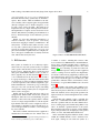
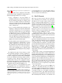
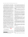
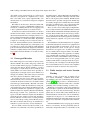
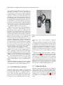
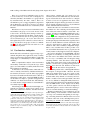
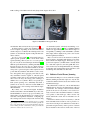
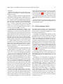
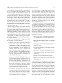
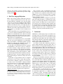
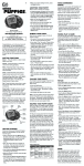
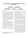
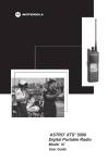
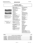
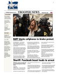
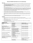
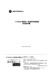
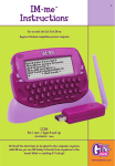
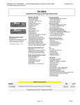
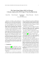
In Proceedings of the 20th Usenix Security Symposium, August 10-12, 2011
1
Why (Special Agent) Johnny (Still) Can’t Encrypt:
A Security Analysis of the APCO Project 25 Two-Way Radio System
Sandy Clark
Travis Goodspeed
Perry Metzger
Zachary Wasserman
Matt Blaze
University of Pennsylvania
APCO Project 25 (“P25”) is a suite of wireless communications protocols used in the US and elsewhere for
public safety two-way (voice) radio systems. The protocols include security options in which voice and data traffic can be cryptographically protected from eavesdropping. This paper analyzes the security of P25 systems
against both passive and active adversaries. We found a
number of protocol, implementation, and user interface
weaknesses that routinely leak information to a passive
eavesdropper or that permit highly efficient and difficult
to detect active attacks. We introduce new selective subframe jamming attacks against P25, in which an active
attacker with very modest resources can prevent specific
kinds of traffic (such as encrypted messages) from being received, while emitting only a small fraction of the
aggregate power of the legitimate transmitter. We also
found that even the passive attacks represent a serious
practical threat. In a study we conducted over a two year
period in several US metropolitan areas, we found that
a significant fraction of the “encrypted” P25 tactical radio traffic sent by federal law enforcement surveillance
operatives is actually sent in the clear, in spite of their
users’ belief that they are encrypted, and often reveals
such sensitive data as the names of informants in criminal investigations.
1
Introduction
APCO Project 25 [16] (also called “P25”) is a suite of
digital protocols and standards designed for use in narrowband short-range (VHF and UHF) land-mobile wireless two-way communications systems. The system is
intended primarily for use by public safety and other government users.
The P25 protocols are designed by an international
consortium of vendors and users (centered in the United
Kevin Xu
States), coordinated by the Association of Public Safety
Communications Officers (APCO) and with its standards
documents published by the Telecommunications Industry Association (TIA). Work on the protocols started in
1989, with new protocol features continuing to be refined
and standardized on an ongoing basis.
The P25 protocols support both digital voice and low
bit-rate data messaging, and are designed to operate in
stand-alone short range “point-to-point” configurations
or with the aid of infrastructure such as repeaters that
can cover larger metropolitan and regional areas.
P25 supports a number of security features, including
optional encryption of voice and data, based on either
manual keying of mobile stations or “over the air” rekeying (“OTAR” [15]) through a key distribution center.
In this paper, we examine the security of P25 (and
common implementations of it) against unauthorized
eavesdropping, passive and active traffic analysis, and
denial-of-service through selective jamming.
This paper has three main contributions: First, we
give an (informal) analysis of the P25 security protocols
and standard implementations. We identify a number of
limitations and weaknesses of the security properties of
the protocol against various adversaries as well as ambiguities in the standard usage model and user interface
that make ostensibly encrypted traffic vulnerable to unintended and undetected transmission of cleartext. We also
discovered an implementation error, apparently common
to virtually every current P25 product, that leaks station
identification information in the clear even when in encrypted mode.
Next, we describe a range of practical active attacks
against the P25 protocols that can selectively deny service or leak location information about users. In particular, we introduce a new active denial-of-service attack,
selective subframe jamming, that requires more than an
In Proceedings of the 20th Usenix Security Symposium, August 10-12, 2011
order of magnitude less average power to effectively jam
P25 traffic than the analog systems they are intended to
replace. These attacks, which are difficult for the enduser to identify, can be targeted against encrypted traffic
(thereby forcing the users to disable encryption), or can
be used to deny service altogether. The attack can be
implemented in very simple and inexpensive hardware.
We implemented a complete receiver and exciter for an
effective P25 jammer by installing custom firmware in a
$15 toy “instant messenger” device marketed to pre-teen
children.
Finally, we show that unintended transmission of
cleartext commonly occurs in practice, even among
trained users engaging in sensitive communication. We
analyzed the over-the-air P25 traffic from the secure
two-way radio systems used by federal law enforcement
agencies in several metropolitan areas over a two year
period and found that a significant fraction of highly sensitive “encrypted” communication is actually sent in the
clear, without detection by the users.
2
P25 Overview
P25 systems are intended as an evolutionary replacement for the two-way radio systems used by local public
safety agencies and national law enforcement and intelligence services. Historically, these systems have used
analog narrowband FM modulation. Users (or their vehicles) typically carry mobile transceivers1 that receive
voice communications from other users, with all radios
in a group monitoring a common broadcast channel. P25
was designed to be deployed without significant change
to the user experience, radio channel assignments, spectrum bandwidth used, or network topology of the legacy
analog two-way radio systems they replace, but adding
several features made possible by the use of digital modulation, such as encryption.
Mobile stations (in both P25 and legacy analog) are
equipped with “Push-To-Talk” buttons; the systems are
half duplex, with at most one user transmitting on a given
channel at a time. The radios typically either constantly
receive on a single assigned channel or scan among multiple channels. P25 radios can be configured to mute received traffic not intended for them, and will ignore received encrypted traffic for which a correct decryption
key is not available.
P25 mobile terminal and infrastructure equipment is
manufactured and marketed in the United States by
1 Various radio models are designed be installed permanently in vehicles or carried as portable battery-powered “walkie-talkies”.
2
Figure 1: Motorola XTS5000 Handheld P25 Radio
a number of vendors, including E.F. Johnson, Harris, Icom, Motorola, RELM Wireless and Thales/Racal,
among others. The P25 standards employ a number of
patented technologies, including the voice codec, called
IMBE [17]. Cross-licensing of patents and other technology is standard practice among the P25 equipment
vendors, resulting in various features and implementation details common among equipment produced by different manufacturers. Motorola is perhaps the dominant
U.S. vendor, and in this paper, we use Motorola’s P25
product line to illustrate features, user interfaces, and attack scenarios. A typical P25 handheld radio is shown in
Figure 1.
For compatibility with existing analog FM based radio systems and for consistency with current radio spectrum allocation practices, P25 radios use discrete narrowband radio channels (and not the spread spectrum techniques normally associated with digital wireless communication).
Current P25 radio channels occupy a standard 12.5
KHz “slot” of bandwidth in the VHF or UHF land mobile radio spectrum. P25 uses the same channel allocations as existing legacy narrowband analog FM two-way
radios. To facilitate a gradual transition to the system,
P25-compliant radios must be capable of demodulating
legacy analog transmissions, though legacy analog radios
cannot, of course, demodulate P25 transmissions.
In the current P25 digital modulation scheme, called
C4FM, the 12.5kHz channel is used to transmit a fourlevel signal, sending two bits with each symbol at a
In Proceedings of the 20th Usenix Security Symposium, August 10-12, 2011
rate of 4800 symbols per second, for a total bit rate of
9600bps.2
P25 radio systems can be configured for three different network topologies, depending on varying degrees of
infrastructural support in the area of coverage:
• Simplex configuration: All group members set
transmitters and receiver to receive and broadcast on
the same frequency. The range of a simplex system
is the area over which each station’s transmissions
can be received directly by the other stations, which
is limited by terrain, power level, and interference
from co-channel users.
• Repeater operation: Mobile stations transmit on one
frequency to a fixed-location repeater, which in turn
retransmits communications on a second frequency
received by all the mobiles in a group. Repeater
configurations thus use two frequencies per channel. The repeater typically possesses both an advantageous geographical location and access to electrical power. Repeaters extend the effective range of
a system by rebroadcasting mobile transmissions at
higher power and from a greater height
• Trunking: Mobile stations transmit and receive on a
variety of frequencies as orchestrated by a “control
channel” supported by a network of base stations.
By dynamically allocating transmit and receive frequencies from among a set of allocated channels,
scarce radio bandwidth may be effectively time
and frequency domain multiplexed among multiple
groups of users.
For simplicity, this paper focuses chiefly on weaknesses and attacks that apply to all three configurations.
As P25 is a digital protocol, it is technically straightforward to encrypt voice and data traffic, something that
was far more difficult in the analog domain systems it
is designed to replace. However, P25 encryption is an
optional feature, and even radios equipped for encryption still have the capability to operate in the clear mode.
Keys may be manually loaded into mobile units or may
be updated at intervals using the OTAR protocol.
P25 also provides for a low-bandwidth data stream
that piggybacks atop voice communications, and for a
higher bandwidth data transmission mode in which data
2 This
12.5 KHz “Phase 1” modulation scheme is designed to coexist with analog legacy systems. P25 also specifies a quadrature phase
shift keying and TDMA and FMDA schemes that uses only 6.25kHz of
spectrum. These P25 “Phase 2” modulation systems have not yet been
widely deployed, but in any case do not affect the security analysis in
this paper.
3
is sent independent of voice. (It is this facility which enables the OTAR protocol, as well as attacks we describe
below to actively locate mobile users.)
2.1
The P25 Protocols
This section is a brief overview of the most salient features of the P25 protocols relevant to rest of this paper.
The P25 protocols are quite complex, and the reader is
urged to consult the standards themselves for a complete
description of the various data formats, options, and message flows. An excellent overview of the most important
P25 protocol features can be found in reference [6].
The P25 Phase 1 (the currently deployed version) RFlayer protocol uses a four level code over a 12.5kHz
channel, sending two bits per transmitted symbol at 4800
symbols per second or 9600 bits per second.
A typical transmission consists of a series of frames,
transmitted back-to-back in sequence. The start of each
frame is identified by a special 24 symbol (48 bit) frame
synchronization pattern.
This is immediately followed by a 64 bit field containing 16 bits of information and 48 bits of error correction.
12 bits, the NAC field, identify the network on which the
message is being sent – a radio remains muted unless
a received transmission contains the correct NAC, which
prevents unintended interference by distinct networks using the same set of frequencies. 4 bits, the DUID field,
identify the type of the frame. Either a voice header,
a voice superframe, a voice trailer, a data packet, or a
trunked frame. All frames but the packet data frames are
of fixed length.
Header frames contain a 16 bit field designating the
destination talk group TGID for which a transmission is
intended. This permits radios to mute transmissions not
intended for them. The header also contains information
for use in encrypted communications, specifically an initialization vector (designated the Message Indicator or
MI in P25, which is 72 bits wide but effectively only 64
bits), an eight bit Algorithm ID, and a 16 bit Key ID.
Transmissions in the clear set these fields to all zeros.
This information is also accompanied by a large number
of error correction bits.
The actual audio payload, encoded as IMBE voice
subframes, is sent inside Link Data Units (LDUs). A
voice LDU contains a header followed by a sequence of
nine 144 bit IMBE voice subframes (each of which encodes 20ms of audio, for a total 180ms of encoded audio in each LDU frame), plus additional metadata and
a small amount of piggybacked low speed data. Each
LDU, including headers, metadata, voice subframes, and
TIA-102.BAAA-A
c
In Proceedings of the 20th Usenix Security Symposium, August 10-12, 2011
Header
Logical Link Logical Link Logical Link Logical Link
Data Unit Data Unit 1 Data Unit 2 Data Unit 1 Data Unit 2
4
Terminator
Data Unit
SUPERFRAME
Figure 2: P25 Voice Transmission Framing
(from Project 25 FDMA - Common Air Interface: TIA-102.BAAA-A)
360 msec
TIA-102.BAAA-A
Figure 5-2 Data Units for Voice Messages
240 bits in Figure 5-2.LSD, 32 bits
The sequence
of information
during a voice transmission24isshortLC,
shown
error correction
is 864 symbols
(1728 bits) long.
2 cyclic code words
Hamming words
The
voice
message
begins
with
a
Header,
and
then
continues
with Logical
Link
Voice
A voice transmission thus consists of a header frame
FS 48 bits
21-24
NID 64 bits
Data
Units orlength
LDUs.alternating
The LDUs
alternate
message.144 bits
followed by
an arbitrary
sequence
of until the end of the voice
9-12 13-16 17-20
Theinend
the message
marked
with a terminator. The terminator can follow
LDU frames
twoofslightly
different is
formats
(called
any
of
the
other
voice
data
units.
The
LDU1 and LDU2 frames, which differ in the metadatadetailed structure of the data units is given
in followed
Section 8.
they carry),
by a terminator frame. See Fig-
Jp*\
ure 2. Note that the number of voice LDU1 and LDU2
v 24 Status Symbols //
s 2 bits after every 70 bits
frames to 5.1.1
be sentNotation
in a transmission is not generally
Figure 8-3 Logical Link codes
Data Unit 1 over
known at the
of correction
the transmission,
since makes
it depends
Thestart
error
for voice
extensive use of Reed-Solomon
ES, 240 bits
LSD, 32 bits
on how long
user speaks.
anthe
extension
Galois Field. The common notation for this 24type
of code
is:
short Hamming
words
2 cyclic code words
RS = Reed-Solomon,
RS code" FS 48 bits
Voice
LDU1 frames contain
the source unit IDasofina "an
given
144 bits
NID 64 bits
radio (a 24 bit field),
and
either
a
24
bit
destination
unit
GF(26) = extension Galois Field with 26=64 elements,
5-8 19-12 113-16 117-20
ID (for point to point transmissions)
or a arithmetic"
16 bit TGID
as in MGF(26)
(for group transmissions).
hex bit = 6-bit symbol for one of the elements of the GF(26) field
LDU2 frames contain new MI, Algorithm ID and
Key ID fields.
Voice LDU codes
frames are
alternate
between
Error correcting
usually
denoted by their block
length parameters, n, k,
\\ 24 Status Symbols //
^ 2 bits after every 70 bits
d. Theformat.
lengthBecause
of the code
block is n. The number
of information
the LDU1and
and LDU2
all theword
metadata
Figure 8-4 Logical Link Data Unit 2
required tosymbols
recognize
a
transmission
is
available
over
in the code word is k. The minimum8.2.3Hamming
distance between code
Terminator Data Units
d. The
codea is
then denoted
by theThere
triplet
(n,k,d) as in "(24,12,8) Golay
the coursewords
of twoisLDU
frames,
receiver
can use an
are two terminating data units for voice messages. The simple one
Figure
3:binary
Logical
DataandUnit
structure
(from terminator
Project 25
consists
solely
of a frame
sync
Network
ID. A
more elaborate
code."
all athe
codes in this
description
use
codes,
where
the
LDU1/LDU2
pair Almost
(also called
“superframe”),
to “catch
adds a Link Control word. These are diagrammed in Figures 8-5 and 8-6.
FDMA
Common
Air
Interface:
TIA-102.BAAA-A)
up with” aparameters
transmission n,
even
if
the
initial
transmission
k, and d are in bits. The only exceptions are the Reed-Solomon
The simple terminating data unit is intended for simple operation. At the end of a
/p^\
ofmessage,
6 bitstheeach,
bits. The
header wascodes
missed.where the parameters are for symbols
voice
transmitter i.e.,
sustainshex
the transmission
until the Link Data Unit
of Section 8.2.2 is completed. This is done by encoding silence for the voice. At
reader
can
convert
the
RS
code
parameters
to
dimensions
of
bits
by
multiplying
See Figure 3 for the structure of the LDU1 and LDU2
the end of the Link Data Unit, the transmitter then sends the simple terminating
this
means that the encoding of voice over the air is more
data unit to signify the end of the message. The terminating data unit may follow
frames. the n and k parameters by 6.
either LDU1 or
efficient,
it LDU2.
also means that voice transmissions are not
Terminator units, which may follow either an LDU1
protected by with block ciphers or message authenticaSystematic
for all voice information.
Each
code word
or LDU2 frame,
indicatecodes
the endare
of aused
transmission.
tion codes, as
we explain
below.contains n
symbols.
The
first
k
symbols
in
the
left
hand
part
of
the
code
word
contain the
A separate format exists for (non-voice) packet data
information. The last n-k symbols in the right hand part contain the parity checks
frames. Data frames may optionally request acknowlfor the code word.
2.2 Security Features
edgment to permit immediate retransmission in case of
corruption.5.1.2
A header,
which Bits
is always
P25 provides options for traffic confidentiality using
Reserved
and unencrypted,
Null Bits indicates which unit ID has originated the packet or is its
symmetric-key ciphers, which can be implemented in
In many
places
in theimportant
followinginformats,
are extra
bits whichThe
have
no
target. (These
features
will prove
the dis- there
software
or hardware.
standard
supports massare labeled as reserved
bits
or
sometimes
as
null
cussion ofassigned
active radiofunctions.
localizationThese
attacks.)
market “Type 2/3/4” crypto engines
(such as DES and
Reserved
are reserved
forown
future AES)
standard
definitions. They are not
Trunkingbits.
systems
also usebits
a frame
type of their
for unclassified domestic and export users, as well
intended
to
allow
non-standard
implementations,
but
to allow future revisions to
on their control channel. (We do not discuss the details
as NSA-approved “Type 1” cryptography for governthe
document.
Transmitters
which
conform
to
the
standard
definitions should
of this frame type, as they are not relevant to our study.)
ment classified traffic. (The use of Type 1 hardware is
encode the reserved bits with nulls (zeros). Receivers should ignore these fields.
tightly controlled and restricted to classified traffic only;
It is important to note a detail of the error correction
even sensitive criminal law enforcement surveillance opcodes usedFor
for the
voice
data
in
LDU1
and
LDU2
frames.
some fields, not all of the available values
are defined. For example, the
erations typically must use commercial Type 2/3/4 crypThe IMBE codec has the feature that not all bits in the
Data Unit ID field in Section 8.5.1 has sixteen possible values, but not all of them
tography.)
encoded representation are of equal importance in regenThe DES, 3DES and AES ciphers are specified in the
erating the original transmitted speech. To reduce the
standard, in addition to the null cipher for cleartext. The
amount of error correction needed in the frame, bits that
standard also provides for the use of vendor-specific procontribute more to intelligibility receive more error corprietary algorithms (such as 40 bit RC4 for radios aimed
rection than those that contribute less, with the least imat the export market). [13]
portant bits receiving no error correction at all. Although
In Proceedings of the 20th Usenix Security Symposium, August 10-12, 2011
At least for unclassified Type 2, 3 and 4 cryptography,
pre-shared symmetric keys are used for all traffic encryption. The system requires a key table located in each
radio mapping unique Key ID+Algorithm ID tuples to
particular symmetric cipher keys stored within the unit.
This table may be keyed manually or with the use of an
Over The Air Rekeying protocol. A group of radios can
communicate in encrypted mode only if all radios share
a common key (labeled with the same Key ID).
Many message frame types contain a tuple consisting
of an initialization vector (the MI), a Key ID and an Algorithm ID. A clear transmission is indicated by a zero
MI and KID and a special ALGID. The key used by a
given radio group may thus change from message to message and even from frame to frame (some frames may be
sent encrypted while others are sent in the clear).
Because of the above-described property of the error
correction mechanisms used, especially in voice frames
such as the LDU1 and LDU2 frame types, there is no
mechanism to detect errors in certain portions of transmitted frames. This was a deliberate design choice, to
permit undetected corruption of portions of the frame
that are less important for intelligibility.
This error-tolerant design means that standard block
cipher modes (such as Cipher Block Chaining) cannot be
used for voice encryption; block ciphers require the accurate reception of an entire block in order for any portion of the block to be correctly decrypted. P25 voice
encryption is specified stream ciphers, in which a cryptographic keystream generator produces a pseudorandom
bit sequence that is XORd with the data stream to encrypt
(on the transmit side) and decrypt (on the receive side).
In order to permit conventional block ciphers (including
DES and AES) to be used as stream ciphers, they are run
in Output Feedback mode (“OFB”)) in order to generate a keystream. (Some native stream ciphers, such as
RC4, have also been implemented by some manufacturers, particularly for use in export radios that limited to
short key lengths.)
For the same reason – received frames must tolerate
the presence of some bit errors – cryptographic message
authentication codes (“MACs”), which fail if any bit errors whatsoever are present, are not used.3
3
Security Deficiencies
In the previous section, we described a highly ad hoc,
constrained architecture that, we note, departs in signif3 Some vendors support AES in GCM mode, but it is not standardized. In any case, even when GCM mode is used, it does not authenticate the voice traffic as originating with a particular user.
5
icant ways from conservative security design, does not
provide clean separation of layers, and lacks a clearly
stated set of requirements against which it can be tested.
This is true even in portions of the architecture, such
as the packet data frame subsystem, which are at least in
theory compatible with well understood standard cryptographic protocols, such as those based on block ciphers
and MACs.
This ad hoc design might by itself represent a security
concern. In fact, the design introduces significant certificational weaknesses in the cryptographic protection provided.
But such weaknesses do not, in and of themselves,
automatically result in exploitable vulnerabilities. However, they weaken and complicate the guarantees that can
be made to higher layers of the system. Given the overall complexity of the P25 protocol suite, and especially
given the reliance of upper layers such as the OTAR subsystem on the behavior of lower layers, such deficiencies
make the security of the overall system much harder for
a defender to analyze.
The P25 implementation and user interfaces, too, suffer from an ad hoc design that, we shall see, does not fare
well against an adversarial threat. There is no evidence in
the standards documents, product literature, or other documentation of user interface or usability requirements, or
of testing procedures such as “red team” exercises or user
behavior studies.
As we shall see later in this paper, taken in combination, the design weaknesses of the P25 security architecture and the standard implementations of it admit practical, exploitable vulnerabilities that routinely leak sensitive traffic and that allow an active attacker remarkable
leverage.
At the root of many of the most important practical
vulnerabilities in P25 systems are a number of fundamentally weak cryptographic, security protocol, and coding design choices.
3.1
Authentication and Error Correction
A well known weakness of stream ciphers is that attackers who know the plaintext content of any encrypted portion of transmission may make arbitrary changes to that
content at will simply by flipping appropriate bits in the
data stream. For this reason, it is usually recommended
that stream ciphers be used in conjunction with MACs.
But the same design decision (error tolerance) that forced
the use of stream ciphers in P25 also precludes the use of
MACs.
Because no MACs are employed on voice and most
In Proceedings of the 20th Usenix Security Symposium, August 10-12, 2011
other traffic, even in encrypted mode, it is trivial for an
adversary to masquerade as a legitimate user, to inject
false voice traffic, and to replay captured traffic, even
when all radios in a system have encryption configured
and enabled.
The ability for an adversary to inject false traffic without detection is, of course, a fundamental weakness by itself, but also something that can serve as a stepping stone
to more sophisticated attacks (as we shall see later).
A related issue is that because the P25 voice mode is
real time, it relies entirely on error correction (rather than
detection and retransmission) for integrity. The error correction scheme in the P25 frame is highly optimized for
the various kinds of content in the frame. In particular,
a single error correcting code is not used across the entire frame. Instead, different sections of P25 frames are
error corrected in independent ways, with separate codes
providing error correction for relatively small individual
portions of the data stream. This design leaves the frames
vulnerable to highly efficient active jamming attacks that
target small-but-critical subframes, as we will see in Section 4.
3.2
Unencrypted Metadata
Even when encryption is used, much of the basic metadata that identifies the systems, talk groups, sender and
receiver user IDs, and message types of transmissions are
sent in the clear and are directly available to a passive
eavesdropper for traffic analysis and to facilitate other
attacks. While some of these fields can be optionally encrypted (the use of encryption is not tied to whether voice
encryption is enabled), others must always be sent in the
clear due to the basic architecture of P25 networks.
For example, the start of every frame of every transmission includes a Network Identifier (“NID”) field that
contains the 12 bit Network Access Code (NAC) and the
4 bit frame type (“Data Unit ID”). The NAC code identfies the network on which the transmission is being sent;
on frequencies that carry traffic from multiple networks,
it effectively identifies the organization or agency from
which a transmission originated. The Data Unit ID identifies the type of traffic, voice, packet data, etc. Several
aspects of the P25 architecture requires that the NID be
sent in the clear. For example, repeaters and other infrastructure (which do not have access to keying material)
use it to control the processing of the traffic they receive.
The effect is that the NAC and type of transmission is
available to a passive adversary on every transmission.
For voice traffic, a Link Control Word (“LCW”) is included in every other LDU voice frame (specifically, in
6
the LDU1 frames). The LCW includes the transmitter’s
unique unit ID (somewhat confusingly called the “Link
IDs” in various places in the standard). The ID fields in
the LCW can be optionally encrypted, but whether they
are actually encrypted is not intrinsically tied to whether
encryption is enabled for the voice content itself (rather
it is indicated by a “protected” bit flag in the LCW).
Worse, we discovered a widely deployed implementation error that exacerbates the unit ID information leaked
in the LCW. We examined the transmitted bitstream generated by Motorola P25 radios in our laboratory, and also
the over-the-air tactical P25 traffic on the frequencies
used by Federal law enforcement agencies in several US
metropolitan areas (captured over a period of more than
one year)
We found that in every P25 transmission we captured,
both in P25 transmissions sent from our equipment and
from encrypted traffic we intercepted over the air, the
LCW protection bit is never set; the option to encrypt
the LCW does not appear ever to be enabled, even when
the voice traffic itself is encrypted. That is, in both Motorola’s XTS5000 product and, apparently, in virtually
every other P25 radio in current use by the Federal government, the sender’s Unit Link ID is always sent in the
clear, even for encrypted traffic. This, of course, greatly
facilitates traffic analysis of encrypted networks by a passive adversary, who can simply record the unique identifiers of each transmission as it comes in. It also simplifies
certain active attacks we discuss in the section below.
3.3
Traffic Analysis and Active Location
Tracking
Generally, a radio’s location may be tracked only if
it is actively transmitting. Standard direction finding techniques can locate a transmitting radio relatively
quickly [12, 10]. P25 provides a convenient means for
an attacker to induce otherwise silent radios to transmit,
permitting active continuous tracking of a radio’s user.
The P25 protocol includes a data packet transmission
subsystem (this is separate from the streaming real-time
digital voice mode we have been discussing). P25 data
packets may be sent in either an unconfirmed mode, in
which retransmission in the event of errors is handled by
a higher layer of the protocol, or in confirmed mode, in
which the destination radio must acknowledge successful
reception of a data frame or request that it be retransmitted.
If the Unit Link IDs used by a target group are already
known to an adversary, she may periodically direct intentionally corrupted data frames to each member of the
In Proceedings of the 20th Usenix Security Symposium, August 10-12, 2011
group. Only the header CRCs need check cleanly for a
data frame to be replied to – the rest of the packet can
be (intentionally) corrupt. Upon receiving a corrupt data
transmission directed to it, the target radio will immediately reply over the air with a retransmission request. (It
is unlikely that such corrupted data frames will be noticed, especially since the corrupt frames are rejected before being passed to the higher layers in the radio’s software responsible for performing decryption and displaying messages on the user interface). The reply transmission thus acts as an oracle for the target radio that not
only confirms its presence, but that can be used for direction finding to identify its precise location.
While we are unaware of any P25 implementations
that refuse to respond to a data frame that is not properly encrypted, even if encryption is enabled and a radio refuses to pass unencrypted frames to higher level
firmware, the attacker may easily construct a forged but
valid encryption auxiliary header simply by capturing legitimate traffic and inserting a stolen encryption header.
This is possible because the protocol is optimized to recover from interference and transmission errors. Upon
receiving a damaged packet – whether generated by an
attacker or corrupted from natural causes – the target radio sends a message to request retransmission. This has
the effect of allowing an active adversary to use the data
protocol as an oracle for a given radio’s presence. It also
allows an adversary to force a target radio to transmit on
command, allowing direction finding on demand.
If the target radios’ Unit Link IDs are for some reason
unknown to the attacker, she may straightforwardly attempt a “wardialing” attack in which she systematically
guesses Unit Link IDs and sends out requests for replies,
taking note of which ID numbers respond. However, in
a trunked system or a system using Over the Air Rekeying, or in a system where members of the radio group
occasionally transmit voice in the clear, Link IDs will be
readily available without resorting to wardialing in this
manner.
With this technique, an adversary can easily “turn the
tables” on covert users of P25 mobile devices, effectively
converting their radios into location tracking beacons.
3.4
Clear Traffic Always Accepted
All models of P25 radios of which we are aware will
receive any traffic sent in the clear even when they are
in encrypted mode. There is no configuration option to
reject or mute clear traffic. While this may have some
benefit to ensure interoperability in emergencies, it also
means that a user who mistakenly places the “secure”
7
Figure 4: Motorola KVL3000 Keyloader with XTS5000
Radio
switch in the “clear” position is unlikely to detect the
error.
Because it is difficult to determine that one is receiving
an accidentally non-encrypted signal, messages from a
user unintentionally transmitting in the clear will still be
received by all group members (and anyone else eavesdropping on the frequency), who will have no indication
that there is a problem unless they happen to be actively
monitoring their receivers’ displays during the transmission.
Especially in light of the user interface issues discussed in Section 3.6, P25’s cleartext acceptance policy
invites a practical scenario for cleartext to be sent without detection for extended periods. If some encrypted
users accidentally set their radios for clear mode, the
other users will still hear them. And as long as the (mistakenly) clear users have the correct keys, they will still
hear their cohorts’ encrypted transmissions, even while
their own radios continue transmitting in the clear.
3.5
Cumbersome Keying
The P25 key management model is based on centralized
control. As noted above, in most secure P25 products
(including Motorola’s), key material is loaded into radios
either via a special key variable loader (that is physically
attached by cable to the radio; see Figure 4) or through
the OTAR protocol (via a KMF server on the radio network).
In Proceedings of the 20th Usenix Security Symposium, August 10-12, 2011
There is no provision for individual groups of users
to create ad hoc keys for short term or emergency use
when they find that some members of a group lack the
key material held by the others. That is, there is no
mechanism for peers to engage in public key negotiation
among themselves over the air or for keys to be entered
into radios by hand without the use of external keyloader
hardware.
Thus there is no way for most users in the field to add a
new member to the group or to recover if one user’s radio
is discovered to be missing the key during a sensitive operation. In systems that use automatic over-the-air keying at regular intervals, this can be especially problematic. If common keys get “out of sync” after some users
have updated keys before others have, all users must revert to clear mode for the group to be able to communicate.4 As we will see in the next section, this is a common scenario in practice.
3.6
User Interface Ambiguities
P25 mobile radios are intended to support a range of government and public safety applications, many of which,
such as covert law enforcement surveillance, require both
a high degree of confidentiality as well as usability and
reliability.
While a comprehensive analysis of the user interface
and usability of P25 radios is beyond the scope of this
paper, we found a number of usability deficiencies in the
P25 equipment we examined.
As noted above, the security features of P25 radios assume a centrally-controlled key distribution infrastructure shared by all users in a system. Once cryptographic
keys have been installed in the mobile radios, either by a
manual key loading device or through OTAR, the radios
are intended to be simple to operate in encrypted mode
with little or no interaction from the user. Unfortunately,
we found that the security features are often difficult to
use reliably in practice.5
All currently produced P25 radios feature highly configurable user interfaces. Indeed, most vendors do not
impose any standard user interface, but rather allow the
4 This scenario is a sharp counterexample to the oft-repeated cryptographic folk wisdom (apparently believed as an article of faith by many
end users) that frequently changing one’s keys yields more security.
5 In this section, we focus on examples drawn from Motorola’s P25
product line. Motorola is a major vendor of P25 equipment in the
United States and elsewhere, supplying P25 radios to the federal government as well as state and local agencies. Other vendors’ radios have
similar features; we use the Motorola products strictly for illustration.
We performed some of our experiment with a small encrypted P25
network we set up in our laboratory, using a set of Motorola Model
XTS5000 handheld radios.
8
radio’s buttons, switches and “soft” menus to be customized by the customer. While this may seem an advantageous feature that allows each customer to configure
its radios to best serve its application, the effect of this
highly flexible design is that any given radio’s user interface is virtually guaranteed to have poorly documented
menus, submenus and button functions.
Because the radios are customized for each customer,
the manuals are often confusing and incomplete when
used side-by-side with an end-user’s actual radio. For
example, the Motorola XTS5000 handheld P25 radio’s
manual [14] consists of nearly 150 pages that describe
dozens of possible configurations and optional features,
with incomplete instructions on how to activate features
and interpret displayed information that typically advise
the user to check with their local radio technician to find
out how a given feature or switch works. (Other manufacturers’ radios have a similarly configurable design).
That is, every customer must, in effect, produce a custom user manual that describes how to properly use the
security features as they happen to have been configured.
In a typical configuration for the XTS5000, outbound
encryption is controlled by a rotating switch located on
the same stem as the channel selector knob. We found
it to be easy to accidentally turn off encryption when
switching channels. And other than a small symbol6
etched on this switch, there is little positive indication of
whether or not the radio is operating in encrypted mode.
Figure 5 shows the radio user interface in clear mode;
Figure 6 shows the same radio in encrypted mode.
On the XTS portable radios, a flashing LED indicates
the reception of encrypted traffic. However, the same
LED serves multiple purposes. It glows steady to indicate transmit mode, ”slow” flashes to indicate received
cleartext traffic, a busy channel, or low battery, and ”fast”
flashes to indicate received encrypted traffic. We found
it to be very difficult to distinguish reliably between received encrypted traffic and received unencrypted traffic.
Also, the LED and the “secure” display icon are likely
out of the operator’s field of view when an earphone or
speaker/microphone is used or if the radio is held up to
the user’s ear while listening (or mouth when talking).
The Motorola P25 radios can be configured to give an
audible warning of clear transmit or receive in the form
of a “beep” tone sounded at the beginning of each outgoing or incoming transmission. But the same tone is used
to indicate other radio events, including button presses,
low battery, etc, and the tone is difficult to hear in noisy
6 On Motorola radios, this symbol is a circle with a line through it,
unaccompanied by any explanatory label. This is the also the symbol
used in many automobiles to indicate whether the air condition vents
are open or closed.
In Proceedings of the 20th Usenix Security Symposium, August 10-12, 2011
9
Figure 5: XTS5000 in “Clear” Mode
environments.
In summary, it appears to be quite easy to accidentally
transmit in the clear, and correspondingly difficult to determine whether an incoming message was encrypted or
with what key.
3.7
Discussion
The range of weaknesses in the P25 protocols and implementations, taken individually, might represent only relatively small risks that can be effectively mitigated with
careful radio configuration and user vigilance. But taken
together, they interact in far more destructive ways.
For example, if users are accustomed to occasionally
having keys be out of sync and must frequently switch
to clear mode, the risk that a user’s radio will mistakenly remain in clear mode even when keys are available
increases greatly.
More seriously, these vulnerabilities provide a large
menu of options that increase the leverage for targeted
active attacks that become far harder to defend against.
In the following sections, we describe practical attacks against P25 systems that exploit combinations of
these protocol, implementation and usability weaknesses
to extract sensitive information, deny service, or manipulate user behavior in encrypted P25 systems. We will
also see that user and configuration errors that cause unintended cleartext transmission are very common in practice, even among highly sensitive users.
4
Denial of Service
Recall that P25 uses a narrowband modulation scheme
designed to fit into channels compatible with the current
spectrum management practices for two-way land mobile radio. Unfortunately, although this was a basic design constraint, it not only denies P25 systems the jamming resistance of modern digital spread spectrum systems, it actually makes them more vulnerable to denial
of service than the analog systems they replace. The P25
protocols also permit potent new forms of deliberate interference, such as selective attacks that induce security
downgrades, a threat that is exacerbated by usability deficiencies in current P25 radios.
4.1
Jamming in Radio Systems
Jamming attacks, in which a receiver is prevented from
successfully interpreting a signal by noise injected onto
the over the air channel, are a long-known and widely
studied problem in wireless systems.
In ordinary narrowband channelized analog FM systems, jamming and defending against jamming is a matter of straightforward analysis. The jammer succeeds
when it overcomes the power level of the legitimate
transmitter at the receiver. Otherwise the “capture effect”, a phenomenon whereby the stronger of two signals at or near the same frequency is the one demodulated by the receiver, permits the receiver to continue
to understand the transmitted voice signal. An attacker
may attempt to inject an intelligible signal or actual noise
to prevent reception. In practice, an FM narrowband
jammer will succeed reliably if it can deliver 3 to 6 dB
more power to the receiver than the legitimate transmitter
(to exceed the “capture ratio” of the system). Jamming
in narrowband systems is thus for practical purposes a
roughly equally balanced “arms race” between attacker
In Proceedings of the 20th Usenix Security Symposium, August 10-12, 2011
10
Figure 6: XTS5000 in “Encrypted” Mode
and defender. Whoever has the most power wins.7
In digital wireless systems, the jamming arms race
is more complex, depending on the selected modulation
scheme and protocol. Whether the advantage falls to the
jammer or to the defender depends on the particular modulation scheme.
Spread spectrum systems [5], and especially direct sequence spread spectrum systems, can be made robust
against jamming, either by the use of a secret spreading code or by more clever techniques described in [9, 1].
Without special information, a jamming transmitter must
increase the noise floor not just on a single frequency
channel, but rather across the entire band in use, at sufficient power to prevent reception. This requires far more
power than the transmitter with which it seeks to interfere, and typically more aggregate power than an ordinary transmitter would be capable of. Modern spread
spectrum systems such as those described in the references above can enjoy an average power advantage of
30dB or more over a jammer. That is, in a spread spectrum system operating over a sufficiently wide band, a
jammer can be forced to deliver more than 30dB more
aggregate power to the receiving station than the legitimate transmitter.
By contrast, in a narrow-band digital modulation
scheme such as P25’s current C4FM mode (or the lowerbandwidth Phase 2 successors proposed for P25), jamming requires only the transmission of a signal at a level
near that of the legitimate transmitter. Competing signals arriving at the receiver will prevent clean decoding
7 As a practical matter, the analog jamming arms race is actually
tipped slightly in favor of the defender, since the attacker generally also
has to worry about being discovered (and then eliminated) with radio
direction finding and other countermeasures. More power makes the
jammer more effective, but also easier to locate.
of a transmitted symbol, effectively randomizing or setting the received symbol. [2] That is, C4FM modulation
suffers from approximately the same inherent degree of
susceptibility to jamming as narrowband FM – a jammer
must simply deliver slightly more power to the receiver
than the legitimate transmitter.
But, as we will see below, the situation is actually far
more favorable to the jammer than analysis of its modulation scheme alone might suggest. In fact, the aggregate
power level required to jam P25 traffic is actually much
lower than that required to jam analog FM. This is because an adversary can disrupt P25 traffic very efficiently
by targeting only specific small portions of frames to jam
and turning off its transmitter at other times.
4.2
Reflexive Partial Frame Jamming
We found that the P25 protocols are vulnerable to highly
efficient jamming attacks that exploit not only the narrowband modulation scheme, but also the structure of the
transmitted messages.
Most P25 frames contain one or more small metadata
subfields that are critical to the interpretation of the rest
of the frame. For example, if the 4-bit Data Unit ID,
present at the start of every frame, is not received correctly, receivers cannot determine whether it is a header,
voice, packet or other frame type. This is not the only
critical subfield in a frame, but it is illustrative for our
purposes.
It is therefore unnecessary for an adversary to jam the
entire transmitted data stream in order to prevent a receiver from receiving it. It is sufficient for an attacker to
prevent the reception merely of those portions of a frame
that are needed for the receiver to make sense of the rest
In Proceedings of the 20th Usenix Security Symposium, August 10-12, 2011
of the frame.
Unfortunately, the P25 frame encoding makes it particularly easy and efficient for a jammer to attack these
subfields in isolation.
A P25 voice frame is 1728 bits in length. The entire
NID subfield containing the NAC + DUID (and its error
correction code) represents only 64 bits of these 1728
bits. Jamming just the 64 bit NID subfield effectively
denies the receiver the ability to interpret the other 1664
bits of the frame, even if those bits are received unmolested . A jammer synchronized to attack just the NID
subfield of voice transmission would need to operate at
a duty cycle of only 3.7% during transmissions. Such a
pulse lasts only about 1/100th of a second.
To efficiently jam particular frame subfields, a jammer must synchronize its transmissions so that it begins
transmitting at or just before the the first symbol of the
targeted field is sent by the transmitter under attack, and
end just after the last symbol of the field has been sent. At
4800 symbols per second, each symbol lasts just longer
than 0.2ms. This may seem at first to require an impossibly high degree of timing synchronization. But the P25
framing scheme actually makes it quite straightforward
for a jammer equipped with its own receiver to tightly
synchronize to the target transmitter. Recall that each
frame begins with an easily-recognized frame synchronization word, which the jammer can use to precisely
trigger its interference so that it begins and ends at exactly the desired symbols.
By careful synchronization, a jammer that attacks only
the NID subfield of voice traffic can reduce its overall
energy output so that it effectively has more than 14dB of
average power advantage over the legitimate transmitter.
It may be possible to improve the advantage to the
jammer even more by careful analysis of the error correction codes used in particular subfields in order to reduce
the number of bits in the subfield that have to be jammed.
(We assumed conservatively above that the attacker must
jam every bit of the 64 bit NID field in order to prevent
correct reconstruction of at least one bit of the NID payload, which clearly can be improved upon). This would
permit even lower transmission times and average emitted power. It is not necessary to fully obliterate a critical
protocol, merely to reliably (though not necessarily perfectly) prevent its correct interpretation.
Properly synchronized, a P25 jamming system can operate at a very low duty cycle that not only saves energy
at the jammer and makes its equipment smaller and less
expensive, but also makes the existence of the attack difficult to diagnose and detect, and, if detected, require the
use of specialized equipment to locate it. (Note that the
11
length of the jamming transmission is only about 10ms
long, which is far shorter than the “oracle” transmissions
discussed in Section 3.3.) Such a jamming system need
only be relatively inexpensive, requires only a modest
power supply, and is trivial to deploy in a portable configuration that carries little risk to the attacker, as described
below.
We note that there is no analogous low-duty cycle jamming attack possible against the narrowband FM voice
systems that P25 replaces.
4.3
Selective Jamming Attacks
An attacker need not attempt to jam every transmitted
frame. The attacker can pick and choose which frames to
attack in order to encourage the legitimate users to alter
their behavior in particular ways.
For example, it is straightforward to monitor for a nonzero MI field in a header frame (indicating an encrypted
transmission) and to selectively jam portions of subsequent frames, while leaving clear transmissions alone, in
order to create the impression to the users of a radio network that, for unknown technical reasons, encryption has
malfunctioned while clear transmission remains viable,
thus inducing the users to downgrade to clear transmissions. If the users are already conditioned (through other
weaknesses in P25) to unreliable cryptography, such an
attack might be dismissed as routine. As we discuss in
Section 5, it appears to be reasonable to expect that many
such users are so conditioned.
As another possibility, an attacker could choose to attack only uplink messages on the control channel of a
trunked P25 system, thus effectively denying use of the
entire trunked network at an extremely low cost to the
attacker.
In addition to the complexities of detecting and
direction-finding an attack lasting mere hundredths or
even thousandths of a second, adversaries can take steps
to render their attacks less vulnerable to detection and
more difficult for the operators of a radio network to
prevent. For example, an attacker could choose to deploy multiple battery operated jamming devices in a
metropolitan area, placing them in public locations to
make tracing of the devices harder, or even surreptitiously attaching them to the vehicles of third parties
such as taxis or delivery trucks to cause confusion, and
to make the jammers harder to locate. Such devices may
be made arbitrarily programmable, changing which of a
group of devices is active at any one time or even taking
commands over the air.
In Proceedings of the 20th Usenix Security Symposium, August 10-12, 2011
12
P25 FrameSync
LDU NID
55 75 F5 FF 77 FF 29 3A B8 A4 ... <−Normal
55 75 F5 FF 77 FF 01 20 75 85 ... <−Jammed
Jammer
RX State
State
Transition
Jammer
TX State
Figure 8: Sub-Frame Reflex Jamming
Figure 7: Girltech IMME, with modified firmware
4.4
Experimental Results
To confirm that low duty cycle subframe jamming is
effective against standard P25 receiver implementations
and to examine practical jammer architectures that might
be employed by an adversary, we implemented a lowpower subframe jammer for P25 traffic for testing in our
laboratory environment.
Recent work has shown that inexpensive software programmable radios such as the Ettus USRP are capable of
implementing the P25 protocols and acting as part of a
P25 deployment [7]. Their versatility and the availability of open-source P25 software makes them attractive
for reception, but round-trip delays between the receiver
and transmitter make the platform less than ideal for subframe jamming.
Instead, we implemented our proof-of-concept selective jammer for P25 frames using the Texas Instruments CC1110 platform. The CC1110 chip combines
a CC1101 radio with an 8051 microcontroller in a single system-on-chip package, allowing for faster reaction
times than a USRP or other software radio could support. When jamming reflexively, packets are passed to
the 8051 one byte at a time, allowing a filter to selectively
jam transmissions only if the received header matches an
intended target.
While any CC1110 board for the correct frequency
range is sufficient, we used the GirlTech IMME, a commercial toy intended for pre-teen children to text message one another without cellular service. Presently
priced at $30 USD, the package includes a handheld unit
and a USB adapter, either of which may be used with our
P25 client (for an aggregate price of $15 per jammer).
In order to facilitate rapid development, our CC1110
toolkit for P25 was divided into a Python-language client
that communicates with native 8051 applications through
an open-source debugger, the GoodFET. [8] Operations
which do not require a fast reaction time are implemented only in Python, while timing-critical operations
such as packet reception and sub-frame jamming are implemented as small fragments of C applications and are
executed from RAM in the CC1110. Once a particular
program has been verified to behave correctly, it can be
rewritten as a stand-alone application to run from flash
memory under battery power.
As shown in Figure 8, our sub-frame jammer is triggered by the LDU Frame Sync bitstream. Upon receiving
this sequence, the CC1101 switches from its Receive to
Transmit states. Starting the transition before the last 8
symbols of the 24-symbol Frame Sync are received allows the jammer-induced packet errors to begin from the
very first byte of an LDU’s NID field. Holding the transmission for the entire duration of the NID subframe and
then ending it immediately produces an overall duty cycle of 3.7% relative to the transmitter under attack.
Our lab experiments were entirely successful. The
GirlTech-based reflexive subframe jammer is able to reliably prevent reception from a nearby Motorola P25
transmitter as received by both a Motorola XTS2500
transceiver and Icom PCR-2500, with the jammer and the
transmitter under attack both operating at similar power
levels and with similar distance from the receiver. A
standard off-the-shelf external RF amplifier would be all
that is necessary to extend this experimental apparatus to
real-world, long-range use. While we did not perform
high power or long-range jamming ourselves (and there
are significant regulatory barriers to such experiments),
we expect that an attacker would face few technical difficulties scaling a jammer within the signal range of a
typical metropolitan area.
5
Encryption Failure in Fielded Systems
Even if the P25 protocols and the design of P25 products
might make them potentially vulnerable to user and configuration error, that does not automatically mean that
fielded P25 systems are always insecure in practice. A
natural question, then, is how successful the users of secure P25 radio systems are in preventing the unintended
transmission of sensitive cleartext.
In Proceedings of the 20th Usenix Security Symposium, August 10-12, 2011
One way to answer this question might be be through
a usability study, such as the one seminally performed by
Whitten and Tygar with PGP [19], in which researchers
train test subjects to configure and use a P25 system and
then observe their behavior and performance in a controlled environment. While such studies can have value
in evaluating, e.g., different user interface designs from
among a set of candidates, they have inherent limitations. Aside from the cost of recruiting and observing
suitable test subjects, it can be difficult to replicate “real
world” conditions – especially the motivation of the users
to maintain security while getting their work done – sufficiently well to ensure that the results are representative
of the system’s true usability under field conditions [3].
Instead, we measured and analyzed the incidence of
unintended cleartext leakage in real P25 systems carrying a high volume of sensitive encrypted traffic with
trained and motivated users: the secure tactical two-way
radio systems used in federal criminal investigations.
An Over-the-Air Analysis
Although P25 is designed for general two-way radio use,
the principal users of P25 in the US are law enforcement
and public safety agencies. P25 has recently enjoyed particularly widespread adoption by the federal government
for the tactical radios used for surveillance and other confidential operations by Federal law enforcement agencies
such as the DEA, FBI, the Secret Service, ICE, and so on.
Most of the P25 tactical radio systems currently used
by these agencies operate in one of two frequency bands
in the VHF and UHF radio spectrum allocated exclusively for Federal use. There are approximately 2000
two-way radio voice channels in the Federal spectrum
allocation (comprising 11 MHz in the VHF band plus
14 MHz in the UHF band, with channels spaced every
12.5 KHz). Most of these channels are unused in any
given geographic area. The individual channels used by
each given agency are assigned on a region-by-region basis, so a channel used by, say, the National Parks Service in one area might be used by the Bureau of Prisons in another area. Channels used for sensitive tactical
law enforcement channels are mixed in among those of
other Federal agencies and likewise vary on a regional
basis. All Federal channel allocations are managed by
the National Telecommunications and Information Administration and, unlike the state, local, and private frequency allocations managed by the Federal Communications Commission, are not published.8
8 Although the Federal agency frequency assignments are not officially published by the government, some of the tactical frequencies
13
We built a P25 traffic interception system for the Federal frequency bands, which we operated over a two year
period in two US metropolitan areas. Our system consists of an array of Icom PCR-2500 software-controlled
radio receivers [11], an inexpensive ($1000) wide-band
receiver marketed to radio hobbyists and also popular in
commercial monitoring applications. The PCR-2500 has
several features that were important to us: relatively good
performance in the federal VHF and UHF frequency
bands, software programmability (via a USB interface),
P25 capability via a daughterboard option, and the ability to search a range of frequencies to identify those in
active use.
Our first task was to identify and catalog the particular frequencies used for sensitive tactical operations in
each of our two metropolitan areas. We programmed
PCR-2500 receivers located at two locations in or near
each city to identify frequencies with P25 signals being
transmitted the federal frequency bands. We live monitored traffic on each identified frequency to determine
whether it is used for law enforcement surveillance or
other sensitive operations. After several months, we positively identified 114 frequencies in one city and 109 in
the other as being used for sensitive law enforcement operations. While some of the frequencies we found carried
a great deal of traffic, many others were only used sporadically. On every one of the sensitive frequencies we
found, the traffic was predominantly encrypted, but still
carried at least occasional cleartext. We could, of course,
only monitor the transmissions that were sent in the clear
(which extended the time required for our frequency cataloging process).9
We then set up infrastructure to intercept every cleartext transmission that occurred on the sensitive frequencies we identified. We dedicated a number of individual
PCR-2500 receivers to intercept traffic on a few particularly active frequencies, in order to ensure that we would
capture virtually all of the cleartext that was transmitted
on them. (The frequencies with dedicated receivers were
the output channels of nearby repeater systems, which
had the desirable effect of ensuring that any transmisused by some agencies in some areas are relatively well known and can
be found on the Internet. But most of the frequencies used for sensitive
tactical communication are not published or widely known.
9 It is explicitly legal under 18 USC 2511 for any person in the US to
intercept and monitor unencrypted law enforcement radio traffic, even
sensitive communication that perhaps should be encrypted. However,
in the interest of public safety, we decline to identify here the particular
frequencies used by particular agencies. Also, to comply with our institutional IRB requirements, we did not retain and will not disclose here
any personally identifiable information we happened to monitor or derive, whether about surveillance targets or the government employees
who were using the radios.
In Proceedings of the 20th Usenix Security Symposium, August 10-12, 2011
sions we did not record were not due to our receiver being out of geographic range but rather due to the traffic being encrypted). For the remaining frequencies, We
used two additional PCR-2500 receiver in different locations around each city to continuously “scan” through
the channels. and capture traffic detected during the scan
(Icom supplies software that performs a similar function, but it did not have sufficient capability to record
the P25 metadata we were concerned with, so we had to
write our own software for this purpose). We operated
this arrangement, on an increasing number of discovered
frequencies and with an increasing number of receivers,
over a period of two years.
We “live sampled” cleartext audio each day. We disregarded “non-sensitive” traffic such as radio tests or other
messages for which encryption would be unnecessary or
inapprpriate (this represented only a small fraction of the
traffic on the frequencies we were monitoring), leaving
only “unintended” sensitive cleartext. We categorized
each unintended cleartext message exchange according
to the apparent error made or other reason it was sent in
the clear. (We did not retain any identifying information
about agents or targets).
In every case, sensitive traffic we sampled was sent in
the clear under one of three scenarios:
• Individual Error: One or more users in the clear,
but other users encrypted. In this scenario, all users
clearly shared a common cryptographic key, since
communication was able to occur unimpeded. But
the users transmitting in the clear apparently accidentally switched their radios to transmit in the
clear mode. Because the offending users still received the other users’ encrypted traffic and because
those users had no way to reliably tell that they were
sometimes getting clear traffic, this situation typically remained undetected.
• Group Error: All users operated in the clear, but
gave an indication that they believed they were operating in encrypted mode. In some cases, this involved one user explaining to another how to set
the radio to encrypted mode, but actually described
the procedure for setting it to clear mode. In other
cases, the users would simply announce that they
had just rekeyed their radios to operated in encrypted mode (but were actually in the clear).
• Keying Failure: One or more users did not have the
correct key, is unable to receive encrypted transmissions, and asks (in the clear) that everyone switch to
clear mode for the duration of an operation so that
all group members are able to participate.
14
Across all agencies, the unintended cleartext we intercepted was roughly evenly split among the Individual
Error, Group Error, and Keying Failure categories. In
general, we found that even when users knew they were
operating in the clear (because they expressly indicated
that they were switching to clear mode due to keying failure) and were engaged in sensitive operations, they made
little effort to conceal the nature of their activity in their
transmissions, and often appeared to “forget” that they
were operating in the clear.
Note that every system we monitored had P25 encryption capability, and, indeed, most of the traffic sent was
apparently successfully encrypted most of the time. Yet
we still intercepted hundreds of hours of very sensitive
traffic that was sent in the clear over the course of two
years. While we will not identify here the agencies, locations, or particular operations involved, we note that
the traffic we monitored routinely disclosed some of the
most sensitive law enforcement information that the government holds, including:
• Names and locations of criminal investigative targets, including those involved in organized crime.
• Names and other identifying features of confidential
informants.
• Descriptions and other characterizing features of
undercover agents.
• Locations and description of surveillance operatives
and their vehicles.
• Details about surveillance infrastructure being employed against particular targets (hidden cameras,
aircraft, etc.).
• Information relayed by Title III wiretap plants.
• Plans for forthcoming arrests, raids and other confidential operations.
During March, April and May 2011, we intercepted
a mean of 23 minutes of unintended sensitive cleartext
per day per city across all monitored frequencies. Note
that the variance was high; on some days, particularly
weekends and holidays, we would capture less than one
minute, while on others, we captured several hours. We
monitored sensitive transmissions about operations by
agents in every Federal law enforcement agency in the
Department of Justice and the Department of Homeland
Security. Most traffic was apparently related to criminal law enforcement, but some of the traffic was clearly
In Proceedings of the 20th Usenix Security Symposium, August 10-12, 2011
related to other sensitive operations, including counterterrorism investigations and executive protection of high
ranking officials.10
6
End-User Stopgap Mitigations
Many of the security problems in P25 arise from basic
protocol design and architectural decisions that cannot
be altered without a substantial, top-to-bottom redesign
of the protocols and of the assumptions under which it
operates. Given the critical and highly sensitive nature
of much of the P25 user base, we strongly urge that a
high priority be placed on such a redesign. However,
until that occurs, there is little that the P25 user can do to
defend against, e.g., the denial of service weaknesses we
identified.
Other vulnerabilities arise from implementation errors
or poor choices made by individual vendors (such as the
transmission of unit IDs in the clear). These can be fixed
without a redesign, but again, P25 users can do little to
defend themselves here except to wait for the vendors to
address these errors and deficiencies.
However, we note that there may be two areas in which
P25 users and system administrators can immediately
reduce the incidence of unintended sensitive cleartext
transmission: improving the configurable of radio user
interfaces and re-thinking their rekeying policies.
At least half of the unintended cleartext we captured
was attributable to some form of “user error”. However,
it would be a mistake to simply dismiss this as carelessness or to focus entirely on user awareness and training.
In fact, these “user” errors are effectively invited by the
radio user interfaces, and it is these interfaces to which
we should assign the blame. But, fortunately, many current P25 radios can be “customer configured” by the enduser’s system manager to make the security state clearer
to the user.
In particular, we suggest that the radios be configured
without the use of the “secure” switch. Instead, encryption should be configured (“strapped”) to be always on
(or always off) for each channel. Displayed channel
names should be chosen to reflect whether encryption is
stropped on or off, e.g., channel ”TAC1” might be renamed instead to “TAC1 Secure” or “TAC1 Clear”. (If
both secure and clear capability are required on the same
frequency, the channel assignment can be duplicated).
10 We
are currently working with the agencies we monitored to help
them improve their radio security practices. However, because many of
the weaknesses that lead to cleartext leakage result from basic properties of the protocols and their implementations, incidents of unintended
cleartext are likely to continue to occur from time to time even with increased user vigilance.
15
The second major cause of unintended cleartext that
we captured arose from users who did not have current
keys, often due to key expiration and the failure of the
OTAR protocol. Some systems rekey weekly or monthly,
and we found that users are inevitably left without current key material as a result.
We suggest that systems be configured to greatly minimize the required frequency of rekeying and to maintain keys for much longer than they are under current
practice. Instead of monthly rekeys, systems should deploy long-lived, non-volatile keys that are changed only
at very long intervals or if an actual compromise (such as
a lost radio) is discovered. This will greatly improve the
likelihood that users who wish to communicate securely
will share common key material when they need it.
7
Conclusions
APCO P25 is a widely deployed protocol aimed at critical public safety, law enforcement, and national security applications. The user base for secure P25 is rapidly
growing in the United States and other countries, especially among federal law enforcement and intelligence
agencies that conduct surveillance and other covert activities against sophisticated adversaries.
As a wireless system, P25 is inherently vulnerable to
passive traffic interception and active attack, and so it
must rely entirely on cryptographic techniques for its optional security features. And yet we found the protocols
and its implementations suffer from serious weaknesses
that leak sensitive data, invite inadvertent clear transmission in “secure” mode, and permit active and passive
tracking and traffic analysis. The protocol is difficult to
use properly even when not under attack, as evidenced
by our interception of large volumes of sensitive cleartext sent by mistake.
The protocol is particularly vulnerable to denial of service. Perhaps uniquely among modern digital voice radio systems, P25 can be effectively jammed with only
a fraction of the aggregate signal power used by the legitimate user, by attackers with low cost equipment and
without access to secrets such as keys or user-specific
codes. Jamming attacks can also be used to aid in the
exploitation of other weaknesses, such as selectively disabling security features to force users into the clear.
It is reasonable to wonder why this protocol, which
was developed over many years and is used for sensitive and critical applications, is so difficult to use and
so vulnerable to attack. We might compare P25 with
other voice encryption protocols and systems, such as the
US Government’s STU-III and STE [18] encrypting tele-
In Proceedings of the 20th Usenix Security Symposium, August 10-12, 2011
phone system used for classified traffic, that perform an
ostensibly similar function and yet do not appear to suffer from such a large number of exploitable deficiencies.
However, we note that P25 is based on a very different
model from that of most cryptographic communication
protocols. In the vast majority of cryptographic protocols, both sender and receiver are active participants in
the protocol, and perform a negotiation or handshake before communication proceeds. In such protocols, both
parties typically have the opportunity to discover and recover from errors, or abort the transaction, before any
data is transmitted. P25, however, while used in “twoway” radio systems, is essentially a unilateral broadcast
system. All cryptographic decisions are made entirely
by the sender, with the receiver only a passive recipient of whatever the sender has transmitted. Protocols for
such broadcast-based encryption have not been as widely
formally studied as other forms of secure communication (with the possible exception of encryption in directbroadcast television systems), and may represent a rich
and difficult class of problem worthy of more attention
by our community. We explore this in more detail in reference [4].
Acknowledgements
We are grateful to Peter Sullivan for many helpful discussions on the practical requirements for public safety
radio systems. Partial support for this work was provided
by a grant from the National Science Foundation, CNS0905434.
References
[1] Leemon C. Baird III, William L. Bahn, Michael, and
D. Collins. Jam-resistant communication without shared
secrets through the use of concurrent codes, 2007.
[2] Stephen Bartlett. Does the digital radio standard come up
short?, ”April” 2001. http://urgentcomm.com/
mag/radio_digital_radio_standard/.
[3] Sacha Brostoff and M. Angela Sasse. Safe and sound: a
safety-critical approach to security. In Proceedings of the
2001 workshop on New security paradigms, NSPW ’01,
pages 41–50, New York, NY, USA, 2001. ACM.
[4] Sandy Clark, Travis Goodspeed, Perry Metzger, Zachary
Wasserman, Kevin Xu, and Matt Blaze. One-Way Cryptography. In Security Protocols Workshop, 2011.
[5] C. Cook and H. Marsh. An introduction to spread spectrum. Communications Magazine, IEEE, 21(2):8 – 16,
March 1983.
16
[6] Daniels.
Daniels Electronics P25 Training Guide,
2009.
http://www.danelec.com/library/
english/p25_training_guide.asp.
[7] Stephen Glass, Marius Portmann, and Muthukkumarasamy Vallipuram. A software-defined radio receiver for apco project 25 signals. In International
Workshop on Advanced Topics in Mobile Computing for
Emergency Management: Communication and Computing Platforms, pages 67–72, Leipzig, Germany, May
2009. ACM.
[8] T. Goodspeed. Open Source JTAG Adapter Project Website. http://goodfet.sourceforge.net.
[9] Wang Hang, Wang Zanji, and Guo Jingbo. Performance
of dsss against repeater jamming. In Electronics, Circuits
and Systems, 2006. ICECS ’06. 13th IEEE International
Conference on, pages 858 –861, dec. 2006.
[10] Nathaniel Husted and Steven Myers. Mobile location
tracking in metro areas: malnets and others. In Proceedings of the 17th ACM conference on Computer and communications security, CCS ’10, pages 85–96, New York,
NY, USA, 2010. ACM.
[11] Icom.
Icom PCR2500 Communications Receiver.
http://www.icomamerica.com/en/
products/pcr2500.
[12] H. T. Kung and D. Vlah. Efficient location tracking using
sensor networks. In Wireless Communications and Networking, 2003. WCNC 2003. 2003 IEEE, volume 3, pages
1954–1961 vol.3. IEEE, 2003.
[13] Motorola.
Motorola P25 Compliance.
http:
//esp.ongov.net/OCICS/documents/
Motorola_P25_Compliant_Features.pdf.
[14] Motorola.
Motorola-USA Digital Portable Radios.
http://www.motorola.com/Business/
US-EN/Business+Product+and+Services/
Two-Way+Radios+-+Public+Safety/P25+
Portable+Radios/XTS5000_US-EN.
[15] Telecommunications Industry Association.
APCO
Project 25 - Over-the-Air-Rekeying(OTAR) Protocol.
Technical Report TIA-102.AACA.
[16] Telecommunications Industry Association. Project 25DataOverview-NewTechStandards.
Technical Report
TIA-102.BAEA-A.
[17] Telecommunications Industry Association. Project 25Vocoder Description Standard. Technical Report TIA102.BABA.
[18] U.S. Department of Defense. STU-III Handbook for Industry. Technical report, February 1997.
[19] Alma Whitten and J. D. Tygar. Why Johnny Cant Encrypt.
In Proceedings of the 8th USENIX Security Symposium,
1999.