1
SIL B
Feeder Relay
USER’S MANUAL
SIL_MANU_SILB_ING_R010_Beta
1.
RECEPTION, HANDLING, INSTALLATION ................................................................... 6
1.1.
Unpackaging ................................................................................................................... 6
1.2.
Reception of relays ........................................................................................................ 6
1.3.
Handling electronic equipment ..................................................................................... 6
1.4.
Installation, commisioning and service ....................................................................... 7
1.5.
Storage ............................................................................................................................ 7
1.6.
Recycling ......................................................................................................................... 7
2.
DIMENSIONS AND CONNECTION DIAGRAMS ............................................................ 8
2.1.
Non compact SILB (with external magnetic module) ................................................. 8
2.1.1.
Equipment front view .................................................................................................... 8
2.1.2.
Equipment dimensions ................................................................................................. 9
2.1.3.
Cut-out pattern ........................................................................................................... 10
2.1.4.
Magnetic module dimensions..................................................................................... 10
2.1.5.
Connection diagrams ................................................................................................. 11
2.1.6.
Terminals.................................................................................................................... 13
2.2.
Compact SILB (without external magnetic module) ................................................. 15
2.2.1.
Equipment front view .................................................................................................. 15
2.2.2.
Equipment dimensions ............................................................................................... 16
2.2.3.
Cut-out pattern ........................................................................................................... 17
2.2.4.
Connection diagrams ................................................................................................. 17
2.2.5.
Terminals.................................................................................................................... 20
3.
DESCRIPTION ............................................................................................................... 26
3.1.
Introduction ................................................................................................................... 26
3.2.
Description .................................................................................................................... 26
3.3.
Functional diagram ...................................................................................................... 32
3.4.
Model list SIL-B ............................................................................................................. 33
3.5.
Phase CT and neutral CT selection ............................................................................ 34
3.5.1.
SIL-B/1 CHARGE CURVE ......................................................................................... 35
3.5.2.
SIL-B/5 CHARGE CURVE ......................................................................................... 35
4.
PROTECTION FUNCTIONS .......................................................................................... 36
4.1.
Functions 50P_1 and 50P_2. Instantaneous phase overcurrent ............................. 36
4.2.
Function 67/51/50P1 & 67/51/50P2. Inverse-time phase directional overcurrent .. 36
4.3.
Functions 50N_1 and 50N_2. Instantaneous neutral overcurrent ........................... 39
4.4.
Function 67/51/50N1 & 67/51/50N2. Inverse-time neutral directional overcurrent 39
4.5.
Function 46. Negative sequence inverse-time overcurrent ..................................... 41
4.6.
Function 49. Thermal image protection ..................................................................... 42
4.6.1.
Thermal image measurement evolution graphic ........................................................ 43
4.6.2.
Thermal image with memory ...................................................................................... 44
4.6.3.
Thermal image measurement display. Reset. ........................................................... 44
4.6.4.
Thermal protection curves.......................................................................................... 45
www.fanox.com
2/309
4.7.
Function 37P. Definite-time phase undercurrent ...................................................... 46
4.8.
Function 59P_1 and 59P_2. Definite-time phase overvoltage ................................. 46
4.9.
Function 59N_1 and 59N_2. Definite-time neutral overvoltage ............................... 47
4.10.
Function 27P_1 and 27P_2. Definite-time phase undervoltage ............................... 47
4.11.
Function 32/40. Definite-time directional overpower ................................................ 48
4.12.
Function 81O/U. Overfrequency and underfrecuency protection ........................... 50
4.13.
Function 52. Circuit Breaker monitoring .................................................................... 51
4.13.1.
Circuit Breaker opening and closing commands ....................................................... 54
4.13.2.
Counter to register the number of openings .............................................................. 55
4.13.3.
Accumulated amps counter: I t .................................................................................. 55
4.13.4.
Maximum openings in a time window ........................................................................ 55
2
4.14.
Function 50BF. Circuit Breaker opening fault ........................................................... 56
4.15.
Function 74TCS. Trip circuit supervision .................................................................. 57
4.16.
Function 79. Autorecloser ........................................................................................... 58
4.16.1.
4.17.
Counter to record the number of reclosings ............................................................... 62
Function 25. Synchronism protection function ........................................................ 62
4.17.1.
Synchronism (25) and recloser (79) ........................................................................... 66
4.17.2.
Syncronism (25) and manual closure (52) ................................................................. 68
4.18.
Cold Load Pickup ......................................................................................................... 69
4.19.
General settings ........................................................................................................... 71
4.20.
Settings Group .............................................................................................................. 72
4.21.
IEC 60255-151 Curves .................................................................................................. 73
4.22.
ANSI-IEEE Curves ........................................................................................................ 77
4.23.
Application examples................................................................................................... 81
5.
MONITORING AND CONTROL .................................................................................... 87
5.1.
Measurements .............................................................................................................. 87
5.2.
Counters ........................................................................................................................ 89
5.3.
Statuses and Events .................................................................................................... 89
5.4.
Fault Report ................................................................................................................ 109
5.5.
Real Time Clock (RTC) ............................................................................................... 109
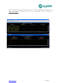
5.6.
Oscillography.............................................................................................................. 109
5.7.
Data Diagram .............................................................................................................. 114
5.8.
Configurable inputs .................................................................................................... 115
5.9.
Configurable Outputs................................................................................................. 117
5.10.
86 Function. Trip output lockout .............................................................................. 120
5.11.
Configurable Leds ...................................................................................................... 120
5.12.
Self-diagnosis ............................................................................................................. 121
5.13.
Commands .................................................................................................................. 122
5.14.
Remote Control ........................................................................................................... 122
5.15.
Date-Time synchronization. IRIG B .......................................................................... 123
www.fanox.com
3/309
5.16.
Test program ............................................................................................................... 124
5.17.
Power Supply .............................................................................................................. 125
6.
TECHNICAL SPECIFICATIONS AND STANDARDS ................................................. 126
6.1.
Technical specifications ............................................................................................ 126
6.2.
Standards .................................................................................................................... 133
7.
COMMUNICATION AND HMI...................................................................................... 135
7.1.
Local communication port. RS232 ........................................................................... 135
7.2.
Remote communications ports. RS485 .................................................................... 136
7.3.
LCD and keypad ......................................................................................................... 138
7.4.
SICom Communications program ............................................................................ 138
7.5.
Setting up the session: Password and access levels ............................................ 139
7.6.
Menus .......................................................................................................................... 140
7.6.1.
Default screen .......................................................................................................... 140
7.6.2.
Last Trip screen ....................................................................................................... 140
7.6.3.
Menu access ............................................................................................................ 140
7.6.4.
Date-Time menu ...................................................................................................... 141
7.6.5.
Fault report ............................................................................................................... 141
7.6.6.
Versions and communications parameters .............................................................. 142
7.6.7.
Test menu ................................................................................................................ 143
7.6.8.
Functions menu ........................................................................................................ 148
7.6.9.
Measurements menu ............................................................................................... 149
7.6.10.
Status menu ............................................................................................................. 154
7.6.11.
Settings menu .......................................................................................................... 187
7.6.12.
Events menu ............................................................................................................ 216
7.6.13.
Counters menu ......................................................................................................... 218
7.6.14.
Commands menu ..................................................................................................... 220
7.6.15.
Input configuration menu.......................................................................................... 223
7.6.16.
Menu for configuration of physical outputs, logical outputs, and LEDs ................... 225
8.
MODBUS RTU PROTOCOL ........................................................................................ 230
8.1.
ModBus package format ............................................................................................ 231
8.2.
Function codes ........................................................................................................... 231
8.3.
Exceptions and error responses .............................................................................. 232
8.4.
Data types ................................................................................................................... 232
8.5.
SIL-B memory map ..................................................................................................... 233
8.6.
Counter map ............................................................................................................... 234
8.7.
Commands map .......................................................................................................... 235
8.8.
Measurements map .................................................................................................... 235
8.9.
Protection criteria map .............................................................................................. 236
8.9.1.
States map ............................................................................................................... 238
8.10.
Event list ...................................................................................................................... 244
www.fanox.com
4/309
8.11.
Settings map ............................................................................................................... 249
8.12.
Examples of Modbus packets ................................................................................... 257
9.
IEC 60870-5-103 PROTOCOL ..................................................................................... 258
9.1.
Physical layer .............................................................................................................. 258
9.2.
Application layer......................................................................................................... 258
10.
IEC 61850 PROTOCOL ............................................................................................... 269
10.1.
Data model .................................................................................................................. 269
10.2.
Services ....................................................................................................................... 278
10.3.
Operation ..................................................................................................................... 281
11.
DNP 3.0 PROTOCOL................................................................................................... 283
11.1.
Device profile document ............................................................................................ 283
11.2.
Implementation table.................................................................................................. 286
11.3.
Point list ...................................................................................................................... 287
11.4.
DNP3 protocol settings .............................................................................................. 292
12.
APPENDIX ................................................................................................................... 293
12.1.
Identification ............................................................................................................... 293
12.2.
Checks ......................................................................................................................... 295
12.3.
Switch configurations ................................................................................................ 295
12.4.
Test menu .................................................................................................................... 295
12.5.
Acceptance setting log .............................................................................................. 295
12.6.
Inputs ........................................................................................................................... 302
12.7.
Input configuration ..................................................................................................... 303
12.8.
Output configuration .................................................................................................. 304
12.9.
LED’s configuration ................................................................................................... 306
12.9.1.
LED’s configuration template ................................................................................... 307
12.10.
Comments ............................................................................................................... 307
www.fanox.com
5/309
1.
RECEPTION, HANDLING, INSTALLATION
1.1.
Unpackaging
Relays must only be handled by qualified personnel and special care must be taken to protect all of
their parts from any damage while they are being unpacked and installed.
The use of good illumination is recommended to facilitate the equipment visual inspection.
The facility must be clean and dry and relays should not be stored in places that are exposed to dust
or humidity. Special care must be taken if construction work is taking place.
1.2.
Reception of relays
It is necessary to inspect the equipment at the time it is delivered to ensure that the relays have not
been damaged during transport.
If any defect is found, the transport company and FANOX should be informed immediately.
If the relays are not for immediate use, they should be returned to their original packaging.
1.3.
Handling electronic equipment
Relays contain an electronic component that is sensitive to electrostatic discharges.
Just by moving, a person can build up an electrostatic potential of several thousand volts.
Discharging this energy into electronic components can cause serious damage to electronic circuits. It
is possible that this damage may not be detected straight away, but the electronic circuit reliability and
life will be reduced. This electronic component in the equipment is well protected by the metal housing,
which should not be removed as the equipment cannot be adjusted internally.
If it is necessary to disassemble the electronic component, this must be carried out with care and
contact with electronic components, printed circuits and connections must be avoided to prevent an
electrostatic discharge that could damage one of the components. If the electronic components are
stored outside the metal housing, they must be placed in an antistatic conductive bag.
If it is necessary to open a module, care must be taken to preserve the equipment reliability and the
duration of the life cycle as designed by the manufacturer by taking the following actions:
• Touch the housing to ensure that you have the same potential
• Avoid touching the electronic components and handle the module by its edges.
• Remember that everyone who handles the module must have the same potential.
• Use a conductive bag to transport the module.
For more information about how to handle electronic circuits, consult official documents such as the
IEC 147-OF.
www.fanox.com
6/309
1.4.
Installation, commisioning and service
The personnel in charge of installing, commissioning and maintaining this equipment must be qualified
and must be aware of the procedures for handling it. The product documentation should be read
before installing, commissioning or carrying out maintenance work on the equipment.
Personnel should take specific protection measures to avoid the risk of electronic discharge when
access is unlocked on the rear part of the equipment.
In order to guarantee safety, the crimp terminal and a suitable tool must be used to meet isolation
requirements on the terminal strip. Crimped terminations must be used for the voltage and current
connections.
It is necessary to connect the equipment to earth through the corresponding terminal, using the
shortest possible cable. As well as guaranteeing safety for the personnel, this connection allows high
frequency noise to be evacuated directly to earth.
The following checks must be performed before the equipment is supplied:
• The rated voltage and polarity.
• The power rating of the CT circuit and the integrity of the connections.
• The integrity of the earth connection.
The equipment must be used within the stipulated electrical and environmental limits.
NOTE: current transformer circuits: Do not open a live CT secondary circuit. The high voltage
produced as a result could damage the isolation and threaten lives.
1.5.
Storage
If the relays are not going to be installed immediately, they must be stored in a dust- and humidity free
environment after the visual inspection has been performed.
1.6.
Recycling
Before recycling the equipment, the capacitors should be discharged through the external terminals.
All electrical power sources should be removed before performing this operation to avoid the risk of
electrical discharge.
This product must be disposed of in a safe way. It should not be incinerated or brought into contact
with water sources like rivers, lakes, etc.
www.fanox.com
7/309
2.
DIMENSIONS AND CONNECTION DIAGRAMS
2.1.
Non compact SILB (with external magnetic module)
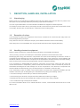
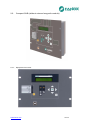
2.1.1.
Equipment front view
www.fanox.com
8/309
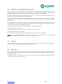
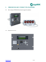
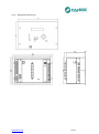
2.1.2.
Equipment dimensions
Dimensions are in mm.
www.fanox.com
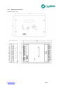
9/309
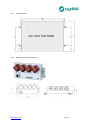
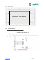
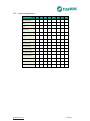
2.1.3.
Cut-out pattern
CUT-OUT PATTERN
2.1.4.
Magnetic module dimensions
www.fanox.com
10/309
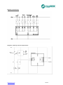
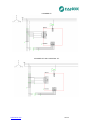
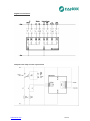
2.1.5.
Connection diagrams
Analogical connections and communications
www.fanox.com
11/309
Digital connections
Outputs and Trip circuit supervision
www.fanox.com
12/309
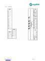
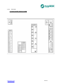
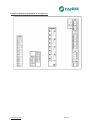
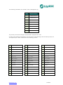
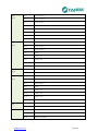
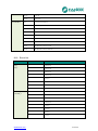
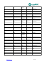
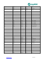
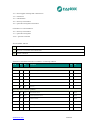
2.1.6.
Terminals
www.fanox.com
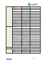
13/309
A1
Digital output common 1
D1
A – RS485 IEC 60870-5-103
A2
Digital output 1 NC
D2
B + RS485 IEC60870-5-103
A3
Digital output 1 NO
D3
Gnd RS485 IEC60870-5-103
A4
Digital output common 2
D4
A – RS485 Modbus RTU
A5
Digital output 2 NC
D5
B + RS485 Modbus RTU
A6
Digital output 2 NO
D6
Gnd RS485 Modbus RTU
A7-A8
Digital output 3 NO
F
RJ45 connector for the external magnetic module
A9-A10
Digital output 4 NO
G1
Phase A voltage +
A11-A12 Digital output 5 NO
G2
Phase A voltage -
A13-A14 Digital output 6 NO
G3
Phase B voltage +
A15-A16 Digital output 7 NO
G4
Phase B voltage -
B1
Digital input 1
G5
Phase C voltage +
B2
Digital input 2
G6
Phase C voltage -
B3
Digital input 3
G7
Busbar Voltage +
B4
Digital input 4
G8
Busbar Voltage -
B5
Common of digital inputs 1, 2, 3 and 4
E1
74TCS voltage presence
C1
Digital input 5
E2
74TCS coil 1
C2
Digital input 6
E3
74TCS coil 2
C3
Digital input 7
E4
74TCS common
C4
Digital input 8
V1
Auxiliary voltage +
C5
Common of digital inputs 5, 6, 7 and 8
V2
Auxiliary voltage -
www.fanox.com
14/309
2.2.
Compact SILB (without external magnetic module)
2.2.1.
Equipment front view
www.fanox.com
15/309
2.2.2.
Equipment dimensions
www.fanox.com
16/309
2.2.3.
Cut-out pattern
CUT-OUT PATTERN
2.2.4.
Connection diagrams
Analog connections and communications
3 PHASES CT AND 1 NEUTRAL CT.
www.fanox.com
17/309
3 PHASES CT.
2 PHASES CT AND 1 NEUTRAL CT.
www.fanox.com
18/309
Digital connections
Outputs and Trip circuit supervision
www.fanox.com
19/309
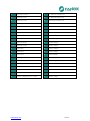
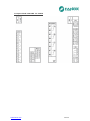
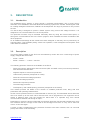
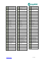
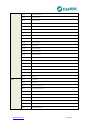
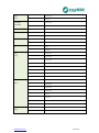
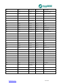
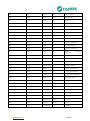
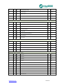
2.2.5.
Terminals
Compact SILB with IEC 61850
www.fanox.com
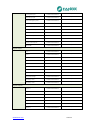
20/309
A1
Digital output common 1
D4
A – RS485 Modbus RTU
A2
Digital output 1 NC
D5
B + RS485 Modbus RTU
A3
Digital output 1 NO
D6
Gnd RS485 Modbus RTU
A4
Digital output common 2
G
RJ45 connector for IEC 61850 protocol
A5
Digital output 2 NC
G1
Phase A voltage +
A6
Digital output 2 NO
G2
Phase A voltage -
A7-A8
Digital output 3 NO
G3
Phase B voltage +
A9-A10
Digital output 4 NO
G4
Phase B voltage -
A11-A12 Digital output 5 NO
G5
Phase C voltage +
A13-A14 Digital output 6 NO
G6
Phase C voltage -
A15-A16 Digital output 7 NO
G7
Busbar Voltage +
B1
Digital input 1
G8
Busbar Voltage -
B2
Digital input 2
E1
74TCS voltage presence
B3
Digital input 3
E2
74TCS coil 1
B4
Digital input 4
E3
74TCS coil 2
B5
Common of digital inputs 1, 2, 3 and 4
E4
74TCS common
C1
Digital input 5
V1
Auxiliary voltage +
C2
Digital input 6
V2
Auxiliary voltage -
C3
Digital input 7
I
IRIG B connector (depending on model)
C4
Digital input 8
C5
Common of digital inputs 5, 6, 7 and 8
www.fanox.com
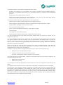
21/309
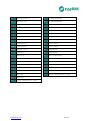
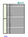
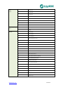
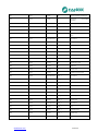
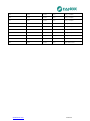
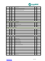
Compact SILB with DNP 3.0 TCP/IP
www.fanox.com
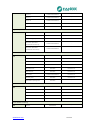
22/309
A1
Digital output common 1
D4
A – RS485 Modbus RTU
A2
Digital output 1 NC
D5
B + RS485 Modbus RTU
A3
Digital output 1 NO
D6
Gnd RS485 Modbus RTU
A4
Digital output common 2
G
RJ45 connector for DNP 3.0 TCP/IP protocol
A5
Digital output 2 NC
G1
Phase A voltage +
A6
Digital output 2 NO
G2
Phase A voltage -
A7-A8
Digital output 3 NO
G3
Phase B voltage +
A9-A10
Digital output 4 NO
G4
Phase B voltage -
A11-A12 Digital output 5 NO
G5
Phase C voltage +
A13-A14 Digital output 6 NO
G6
Phase C voltage -
A15-A16 Digital output 7 NO
G7
Busbar Voltage +
B1
Digital input 1
G8
Busbar Voltage -
B2
Digital input 2
E1
74TCS voltage presence
B3
Digital input 3
E2
74TCS coil 1
B4
Digital input 4
E3
74TCS coil 2
B5
Common of digital inputs 1, 2, 3 and 4
E4
74TCS common
C1
Digital input 5
V1
Auxiliary voltage +
C2
Digital input 6
V2
Auxiliary voltage -
C3
Digital input 7
I
IRIG B connector (depending on model)
C4
Digital input 8
C5
Common of digital inputs 5, 6, 7 and 8
www.fanox.com
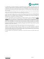
23/309
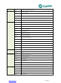
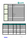
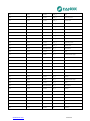
Compact SILB with IEC 60870-5-103 protocol
www.fanox.com
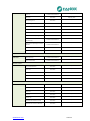
24/309
A1
Digital output common 1
D1
A – RS485 IEC 60870-5-103
A2
Digital output 1 NC
D2
B + RS485 IEC60870-5-103
A3
Digital output 1 NO
D3
Gnd RS485 IEC60870-5-103
A4
Digital output common 2
D4
A – RS485 Modbus RTU
A5
Digital output 2 NC
D5
B + RS485 Modbus RTU
A6
Digital output 2 NO
D6
Gnd RS485 Modbus RTU
A7-A8
Digital output 3 NO
I
IRIG-B (depending on model)
A9-A10
Digital output 4 NO
G1
Phase A voltage +
A11-A12 Digital output 5 NO
G2
Phase A voltage -
A13-A14 Digital output 6 NO
G3
Phase B voltage +
A15-A16 Digital output 7 NO
G4
Phase B voltage -
B1
Digital input 1
G5
Phase C voltage +
B2
Digital input 2
G6
Phase C voltage -
B3
Digital input 3
G7
Busbar Voltage +
B4
Digital input 4
G8
Busbar Voltage -
B5
Common of digital inputs 1, 2, 3 and 4
E1
74TCS voltage presence
C1
Digital input 5
E2
74TCS coil 1
C2
Digital input 6
E3
74TCS coil 2
C3
Digital input 7
E4
74TCS common
C4
Digital input 8
V1
Auxiliary voltage +
C5
Common of digital inputs 5, 6, 7 and 8
V2
Auxiliary voltage -
www.fanox.com
25/309
3.
DESCRIPTION
3.1.
Introduction
The worldwide energy industry is going through a profound transformation. Due to huge energy
demands, more distribution lines with advanced monitoring systems are needed. Assuming the need
for creating intelligent infrastructure, FANOX has developed the SIL range of products to carry out this
function.
The SIL-B relay is designed to protect a feeder system using current and voltage functions. It is
designed to use a circuit breaker as a cut-off component.
The protection functions may be activated selectively either by using the front-mounted panel, or
through the communications link to the SIcom program, which facilitates accurate coordination with
other equipment.
As an additional advantage all the models have been designed so that they can be powered by an
external battery. This facilitates putting centers into operation, event management and specific work
under adverse conditions.
3.2.
Description
The power supply voltage for the SIL-B can be selected by model. We cover a wide range of power
supply voltages with two models:
-
24Vdc – 48Vdc
-
90Vdc – 300Vdc / 110Vac – 230 Vac
The following protection functions are available on the SIL-B:
-
Phase and neutral, definite-time and inverse-time (IEC and ANSI curves) overcurrent protections,
with directional discrimination.
-
Negative sequence overcurrent protection.
-
Undercurrent protection (it depends on model)
-
Phase and neutral overvoltage protection
-
Phase undervoltage protection
-
Directional overpower protection
-
Thermal image protection
-
Overfrequency and underfrequency protection (it depends on the model)
This manual provides full details of the number of available protection units, along with their
parameters and operating characteristics.
As this is a line protection device, it is also fitted with a recloser (79). This automated device allows the
line to be closed up to five times. Each reclosure time can be programmed. The equipment can be
locked in different ways: from the keypad (for which there is a separate key), from remote
communications stations and through an input.
Depending on model, the device is fitted with synchronism protection function that is designed to verify
the conditions that the voltage of both ends of the switchgear must have to carry out to allow the
closure of the switchgear.
A series of other complementary line protection functions have been included, such as cold load
pickup and closure circuit monitoring.
www.fanox.com
26/309
All models include a circuit breaker management block, which:
-
Monitors the condition of the circuit breaker, the number of openings and accumulated amperes. It
generates an indication when there is an excessive number of openings and accumulated
amperes.
-
Determines if an opening fault has occurred
-
Allows circuit breaker opening and closing commands to be given from the HMI (using different
keys) and through local and remote communications
The following measurements are provided by the SIL-B equipment:
-
Phase currents, neutral, positive sequence and negative sequence
-
Phase voltages, voltages between phases, residual neutral voltage and busbar voltage
-
Angle between voltage and current of each phase
-
Cos φ (3-phase and per phase)
-
Active, reactive and apparent powers (3- phase and per phase)
-
Thermal image
-
Line frequency and busbar frequency
-
Phase difference between phase B line voltage and busbar voltage
The SIL-B equipment has eight inputs and seven outputs. Both the inputs and outputs can be
configured by the user.
The SIL-B equipment is housed in a metal case with all measurement and digital inputs and outputs
with galvanic isolation (with the exception of local communications and battery power, as these are
sporadic connections). This gives the equipment the highest degree of electromagnetic compatibility,
both in terms of radiated and conduced EMI and emissivity and immunity. Said levels are those
established for primary substations.
It has an LCD with two rows and twenty columns, and a 6 key membrane keypad. These allow the
state of the equipment, measurements, adjustments to protection criteria and the events or events
associated with the equipment to be displayed.
In addition to the keys used to navigate through the menus, there are some special keys:
Reset. Used to reset signals and events.
Locking 79. Used to lock and unlock the recloser.
I/O of the circuit breaker. Used to control the circuit breaker
The SIL-B has 8 front-mounted LEDs, of which 2 have fixed functions and 6 can be configured. The
LEDs with fixed functions are:
Status of the circuit breaker.
Status of the recloser.
The remaining 6 LEDs are designed to indicate events and can be configured to show alarms and
states.
The equipment has a memory for up to 1000 events, allowing any recorded events to be analyzed.
There may be a very extensive number of fault events, resulting from the use of inverse criteria and
the recloser. As the oscillography is time limited (50 cycles), it may not have the capability to record
the entire fault. Similarly, the events log contains generic information, and it can lose information
pertaining to a specific event after a time. This is why a log of fault reports has been included. Each
fault report contains up to 80 events associated with the time of failure. The log stores the reports
associated with the last 20 faults that are detected.
www.fanox.com
27/309
As mentioned in the previous paragraph, 2 oscillographic logs are available, each with a size of 138
cycles (2.7 seconds at 50Hz, 2.3 seconds at 60Hz): 10 pre-fault cycles and 128 post-fault cycles. The
oscillography start can be configured by the user. Each oscillographic record contains the phase and
neutral currents, the phase and neutral voltages and up to 128 digital channels, which include startups and trips of the protection functions, inputs, outputs, etc. The format used is COMTRADE (IEEE
C37.111-1991).
Current measurements are made using r.m.s. values with a precision of 2% in the 20% band around
rated current. The current transformers used at standard 5A and 1A CTs.
It has three communications ports: one front port (RS232) and two rear ports. Optionally RS485,
plastic optical fiber or Ethernet can be chosen for the physical medium of the ports. The RS232 port
allows a PC to be connected and the equipment to be monitored using the SICom program in
WINDOWS XP or WINDOWS 7 (supplied by FANOX).
The rear communications ports are designed for different functions. One is designed for control,
mainly including the alarm and command functions, and the other is designed for specific queries by
protection staff, who may query or change settings or download events and oscillographs without
interfering with the operation of the command side. Non compact SILB has two RS485 communication
ports, one for MODBUS RTU protocol and the other one for IEC 60870-5-103 protocol. In compact
SILB there are two options: On of those option is the possibility of having two RS485 communication
ports, one for MODBUS RTU protocol and the other one for IEC 60870-5-103 protocol.The other
possibility is having two rear ports, one RS485 for MODBUS RTU protocol and the other one RJ45
(Ethernet) for IEC 61850 or DNP 3.0.
Logging-in allows four levels of access with passcodes that can be configured by the user.
Thanks to the protection functions that are available, its user friendly interface, its reduced
maintenance requirements and simple integration, the SIL-B is an accurate and practical solution for
protecting a feeder system. SIL-B offers protection against earth faults that is sufficiently sensitive for
use with electrical systems with a low earth failure current. It can be adjusted to 0.1 times the rated
current and really low rated levels can be selected.
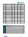
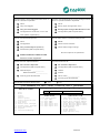
The main features of the equipment are listed below. These will be described in greater detail in this
manual:
www.fanox.com
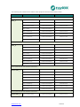
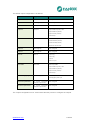
28/309
Function
Description
SIL-B
Protection
50P
Definite-time overcurrent protection function (phase)
2
50N
Definite-time overcurrent protection function (neutral)
2
67/51/50P
Inverse-time overcurrent protection function (phase)
2
67/51/50N
Inverse-time directional overcurrent protection function (neutral)
2
46
Inverse-time overcurrent protection function (negative sequence)
1
49
Thermal image protection function
1
37
Undercurrent protection function
59P
Definite-time overvoltage protection function (phase)
2
59N
Definite-time overvoltage protection function (neutral)
2
27P
Definite-time undervoltage protection function (phase)
2
32/40
Definite-time directional overpower function
4
79
Recloser
25
Synchronism protection function
50BF
Opening failure
1
74TCS
Monitoring of the circuit breaker’s coils
1
81O/U
Overfrequency and underfrequency protection function
86
Trip Output Lockout
2(depending on model)
Up to 5 attempts
1(depending on model)
4(depending on model)
Circuit breaker
www.fanox.com
State and command of the circuit breaker
Counter for the number of openings
Counter for accumulated amperes
Maximum number of openings in a time window
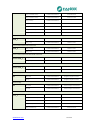
29/309
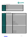
Measurements
Phase and neutral rms currents with a precision of 2% in a band of
±20% when compared to the rated current, and 4% in the rest of the
range.
Negative and positive sequence currents
Phase rms voltages, voltages between phases, residual neutral voltage
and busbar voltage with a precision of 2% in a band of ±20% when
compared to the rated voltage, and 4% in the rest of the range.
Apparent power S (total and per phase)
Active power P (total and per phase)
Reactive power Q (total and per phase)
Power factor: cos φ (total and per phase)
Active and reactive energy
Thermal image
Line frequency and bar frequency
Depending on model
Inputs and Outputs
Configurable inputs
8 to Vaux
Configurable outputs
2 (no-nc) + 5 (no)
Communication and HMI
LOCAL Port: ModBus RTU
REMOTE Port: ModBus RTU
REMOTE Port: IEC 60870-5-103
Depending on model
REMOTE Port: IEC 61850
Depending on model
REMOTE Port: DNP 3.0
Depending on model
SICom Program for Windows XP/7
Session: 4 log-in levels with a configurable password
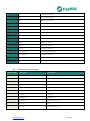
Control and signaling
HMI: LCD, 20x2
6 keys + 1 reset button + 2 command keys for 52 + 1 separate key for
locking 79
LED indicators
8
Power Supply
24VDC-48 VDC
Auxiliary voltage
90VDC–300VDC/110VAC–230VAC
www.fanox.com
30/309
Monitoring and Recording
Events stored in the non-volatile FRAM* memory
1000
2 Logs of
Oscillographic logs in the non-volatile FRAM memory
2.76 s = 10+128 cycles
20 fault reports
Real Time Clock (RTC 1 millisecond)
IRIG-B synchronism
Depending on model
Test menu
Auto-diagnostic
Table of settings
Using keys
Using inputs
3 tables of settings
Using communications
Cold Load Pickup
Activated by current
Multiplying the pickups
Mechanics
Dimensions
www.fanox.com
4U x ½ rack
31/309
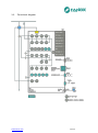
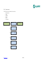
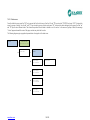
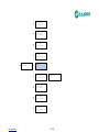
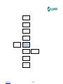
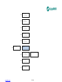
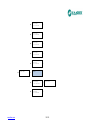
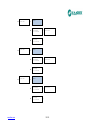
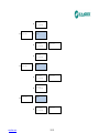
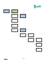
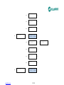
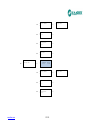
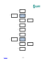
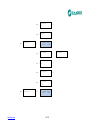
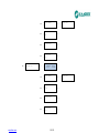
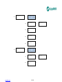
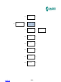
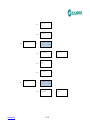
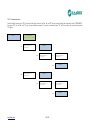
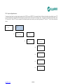
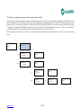
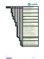
3.3.
Functional diagram
www.fanox.com
32/309
SIL
ADAPTATION
LANGUAGE
MECHANICS
INPUTS - OUTPUTS
COMMUNICATIONS
ADDITIONAL FUNCTIONS
POWER SUPPLY
NET FREQUENCY
NEUTRAL MEASUREMENT
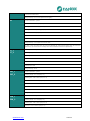
PHASE MEASUREMENT
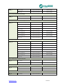
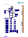
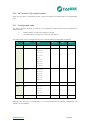
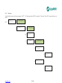
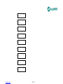
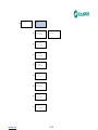
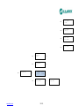
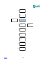
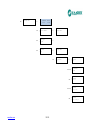
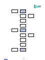
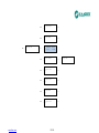
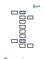
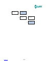
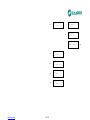
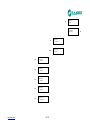
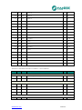
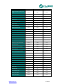
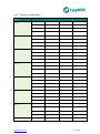
Model list SIL-B
TYPE
3.4.
B
50P(2) + 67P(2) + 50N(2) + 67N(2) + 46 +
59P(2) + 59N(2) + 27P(2) + 32(4) + 52 +
50BF + 79 + 74TCS + Cold Load Pickup +
49+86
1
1A
5
5A
1
1A
5
5A
5
50 Hz
6
60 Hz
A
24 - 48Vcc
B
90 – 300,00Vcc / 110 – 230Vca
0
-
1
+ 81U/O(4) + 25 + 37(2)
2
+ 81U/O(4) + 25 + 37(2) + IRIG-B
0
RS485: ModBus + IEC 60870-5-103
1
FOP: ModBus + IEC 60870-5-103
2
FOC-ST: ModBus + IEC 60870-5-103
----------Compact version--------------
3
IEC61850 + ModBus (RS485)
4
DNP 3.0 + ModBus (RS485)
5
IEC 60870-5-104 + ModBus (RS485)
0
7 outputs + 8 inputs
0
With external MMS module:4U x ½ rack
1
Compact: 4U x ½ rack
A
English, Spanish , French and German
B
English, Spanish, French and Turkish
D
English, Spanish , French and Russian
A
www.fanox.com
-
33/309
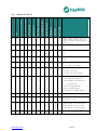
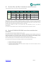
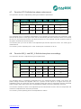
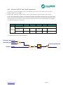
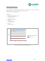
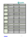
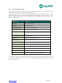
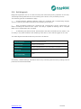
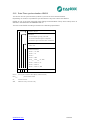
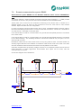
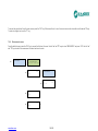
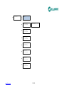
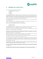
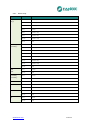
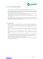
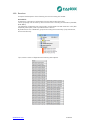
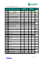
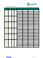
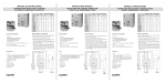
3.5.
Phase CT and neutral CT selection
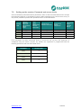
The following table shows a summary of the phase and neutral CT combinations:
Model
Phase
Neutral
Phase range
Neutral range
SIL-B55
CT 5 A
Residual phase connection
1-150 A
1-150 A
SIL-B11
CT 1 A
Residual phase connection
0.2-30 A
0.2-30 A
SIL-B51
CT 5 A
CT 1 A
1-150 A
0.2-30 A
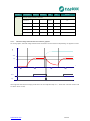
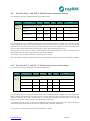
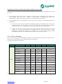
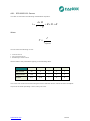
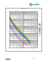
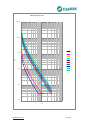
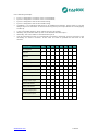
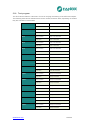
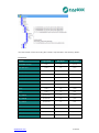
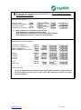
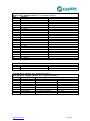
To ensure the relay functions correctly, a suitable current transformer must be used. The load of the
relay’s own measurement circuits and the load on the cables that connect the CTs and the relay must
be taken into account.
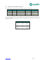
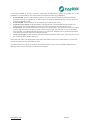
www.fanox.com
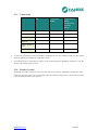
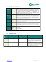
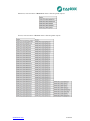
PRECISION
BURDEN
RELAYS
5P10
5P20
5P30
5P10
5P20
5P30
0,5 VA
0,5 VA
0,5 VA
1 VA
1 VA
1 VA
SIL-B/1
SIL-B/1
SIL-B/1
SIL-B/5
SIL-B/5
SIL-B/5
34/309
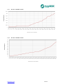
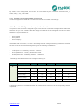
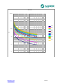
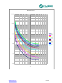
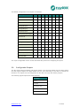
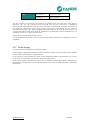
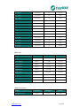
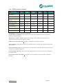
3.5.1.
SIL-B/1 CHARGE CURVE
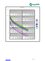
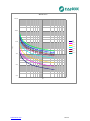
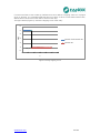
3.5.2.
SIL-B/5 CHARGE CURVE
www.fanox.com
35/309
4.
PROTECTION FUNCTIONS
4.1.
Functions 50P_1 and 50P_2. Instantaneous phase overcurrent
This protection function can be set by using three parameters:
Function
Description
Minimum
Maximum
Step
Unit
Default
50P_1
Instantaneous phase overcurrent
50P_2
Permission
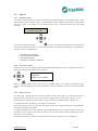
-
-
Yes/No
-
No
Tap
0.10
30.00
0.01
Inominal
5.00
Operating time
0.02
300.00
0.01
s
0.02
The operating time is independent from the operating current flowing through the equipment, so if the
phase current exceeds its predetermined value for an equal or greater amount of time than this preset
value, the protection function activates (trips) and does not reset itself until the average value of the
phase drops below the point of current pick-up.
The function activates at 100% of the preset input, and deactivates at 95%. The reset is
instantaneous.
The accuracy of the operating time is equal to the preset time plus a maximum of 30 ms.
4.2. Function 67/51/50P1 & 67/51/50P2. Inverse-time phase directional
overcurrent
Two phase directional units are available: 67P1 y 67P2.
This function uses the cross phase voltage as a polarization magnitude and the phase current as an
operating magnitude. The intervention sector is defined in the following way: the operating angle is
rotated anticlockwise from the polarization voltage, which gives us the maximum torque direction. A
cone is drawn, with the half-cone angle adjusted, over this maximum torque direction.
If the directionality option is not activated, the 67P function behaves like a 51/50P function.
The actuation time starts when the following conditions are met simultaneously:
Polarization voltage higher than adjusted
Phase current higher than adjusted
The phase shift of phase current and polarization voltage is such that the phase current is
inside the intervention sector.
www.fanox.com
36/309
The function settings are as follows:
Function
Description
Step
Unit
Default
67P_1
Inverse-time phase directional overcurrent
67P_2
Permission
-
-
Yes/No
-
No
Curve
-
-
(1*)
-
IEC Extremely inverse
Dial
0.05
2.20
0.01
-
1.00
Pickup
0.10
30.00
0.01
I rated
5.00
Operating time
0.02
300.00
0.01
s
0.02
-
-
Yes/No
-
No
4.00
110
1
V
5
Operating angle
0
359
1
º
90
Half-cone angle
0
170
1
º
90
Directionality
Polarization voltage
Minimum
Maximum
(1*) IEC Inverse, IEC Very inverse, IEC Extremely Inverse, ANSI inverse, ANSI very inverse, ANSI
extremely inverse, definite-time
If the "definite-time" option is selected for the curve setting, the unit behaves as an instantaneous
directional overcurrent unit. In this case, the unit’s operating time is adjusted using the "Operating
time" parameter.
If an inverse, very inverse or extremely inverse curve is selected in the curve setting, the operating
time is a function of curve, dial and pickup adjustments.
If the unit operates with definite-time, the function starts up at 100% of the adjusted pickup and resets
at 95%.
If the unit operates with a curve, the function starts up at 110% of the adjusted pickup and resets at
100%. Resets are instantaneous in both cases.
The actuation time is accurate to ±5%, o ±30ms, whichever is higher, of the theoretical actuation time.
The curves that are used are IEC 60255-151 and ANSI IEEE, which are described in the
corresponding section.
The activation level for the polarization voltage is 100%, and the reset level is 95%. Resets are
instantaneous.
www.fanox.com
37/309
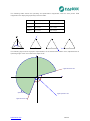
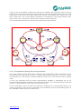
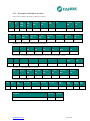
The following table shows the operating and polarization magnitudes used for each phase. Said
magnitudes are displayed graphically below the table.
Phase
Operating magnitude
Polarization magnitude
Phase A
IA Current
VCB Voltage
Phase B
IB Current
VAC Voltage
Phase C
IC Current
VBA Voltage
Ia
+
Va
Ia
Vca
Vba
Vca
Vba
Vca
Vba
Vca
Vba
Ic
Ib
Vc
Vb
Vcb
Vcb
Vb
Ic
Vcb
Vb
Vcb
Vb
Ib
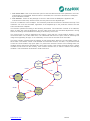
The following figure shows a graphic representation of the directional actuation zone, adjusted with an
operating angle of 90° and a half-cone angle of 60°.
angulo semicono = 60º
Vpolarización
angulo operación = 90º
angulo semicono = 60º
www.fanox.com
38/309
4.3.
Functions 50N_1 and 50N_2. Instantaneous neutral overcurrent
This protection function can be set by using three parameters:
Function
Description
Minimum
Maximum
50N_1
Neutral instantaneous overcurrent
50N_2
Permission
Step
Unit
Default
-
-
Yes/No
-
No
Tap
0.10
30.00
0.01
I nominal
1.00
Operating time
0.02
300..00
0.01
s
0.02
The operating time is completely independent from the operating current that flows through the
equipment, so if the neutral current exceeds its predetermined value for an equal or greater amount of
time than this preset value, the protection function activates (trips) and does not reset itself until the
average value of the phase drops below the point of current tap.
The function activates at 100% of the preset input, and deactivates at 95%. The reset is
instantaneous.
The accuracy of the operation time is equal to the preset time plus a maximum of 30 ms.
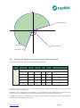
4.4. Function 67/51/50N1 & 67/51/50N2. Inverse-time neutral directional
overcurrent
Two neutral directional units are available: 67N1 y 67N2.
This function uses the residual voltage as a polarization magnitude and the residual current as an
operating magnitude. The intervention sector is defined in the following way: the operating angle is
rotated anticlockwise from the residual voltage, which gives us the maximum torque direction. A cone
is drawn, with the half-cone angle adjusted, over this maximum torque direction.
If the directionality option is not activated, the 67N function behaves like a 51/50N function.
The actuation time starts when the following conditions are met simultaneously:
Residual voltage higher than adjusted
Residual current higher than adjusted
The phase shift of residual current and residual voltage is such that the residual current is
inside the intervention sector.
www.fanox.com
39/309
The function settings are as follows:
Function
Description
Step
Unit
Default
67N_1
Inverse-time neutral directional overcurrent
67N_2
Permission
-
-
Yes/No
-
No
Curve
-
-
(1*)
-
IEC Extremely inverse
Dial
0.05
2.20
0.01
-
1.00
Pickup
0.10
7.00
0.01
I rated
1.00
Operating time
0.02
300.00
0.01
S
0.02
-
-
Yes/No
-
No
4,00
110
1
G
5
Operating angle
0
359
1
º
90
Half-cone angle
0
170
1
º
90
Directionality
Polarization voltage
Minimum
Maximum
(1*) IEC Inverse, IEC Very inverse, IEC Extremely Inverse, ANSI inverse, ANSI very inverse, ANSI
extremely inverse, definite-time
If the "definite-time" option is selected for the curve setting, the unit behaves as an instantaneous
directional overcurrent unit. In this case, the unit’s operating time is adjusted using the "Operating
time" parameter.
If an inverse, very inverse or extremely inverse curve is selected in the curve setting, the operating
time is a function of curve, dial and pickup adjustments.
If the unit operates with definite-time, the function starts up at 100% of the adjusted pickup and resets
at 95%.
If the unit operates with a curve, the function starts up at 110% of the adjusted pickup and resets at
100%. Resets are instantaneous in both cases.
The actuation time is accurate to ±5%, o ±30ms, whichever is higher, of the theoretical actuation time.
The curves that are used are IEC 60255-151 and ANSI IEEE, which are described in the
corresponding section.
The activation level for the residual voltage is 100%, and the reset level is 95%. Resets are
instantaneous.
The following figure shows a graphic representation of the directional actuation zone, adjusted with an
operating angle of 90° and a half-cone angle of 60°.
www.fanox.com
40/309
angulo semicono = 60º
Vpolarización
angulo operación = 90º
angulo semicono = 60º
4.5.
Function 46. Negative sequence inverse-time overcurrent
This protection function can be set by using three parameters:
Function
46
Description
Minimum
Maximum
Step
Unit
Default
Negative sequence inverse-time overcurrent
Permission
-
-
Yes/No
-
No
Curve
-
-
(1*)
-
IEC Extremely Inverse
Dial
0.05
2.20
0.01
-
1.00
Tap
0.10
1.00
0.01
I nominal
0.2
Operating time
0.02
300,0
0.01
s
0.02
(1*) IEC Inverse, IEC Very inverse, IEC Extremely Inverse, ANSI inverse, ANSI very inverse, ANSI
extremely inverse, definite-time
If Definite Time is selected on curve settings, the unit behaves as an instantaneous overcurrent unit.
For this case, unit’s operating time is the one adjusted on the parameter “Operating time”.
If for the curve setting it is selected a curve (inverse, very inverse or extremely inverse), operating time
is function of curve settings, dial and tap.
www.fanox.com
41/309
If the unit operates as a definite time, the starting up of the function occurs with 100% of adjusted tap,
and it resets with the 95%.
If the unit operates with curve, the starting up of the function occurs with the 110% of the adjusted tap
and it resets with the 100%. Reset is instantaneous in both cases.
Action time accuracy is ±5% or ±30ms highest of both, over theorical time of action.
Used curves are IEC 60255-151 and ANSI IEEE, which are described on corresponding section of this
manual.
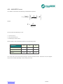
4.6.
Function 49. Thermal image protection
Thermal image is a measure of heating and cooling of an electric machine. Unlike overcurrent
protection, do not start counting the time when it detects a fault, but is continuously determining the
thermal state of the machine that monitors. The trip time depends on the thermal constants adjusted,
the current flowing and the prior thermal state of the machine.
The thermal image is calculated based on the following equation:
θ = 100 x (I/It)2 x (1 – e-t/ζ) + θ’0 x e-t/ζ
where :
I, máximum r.m.s. current of three phases
It, adjusted tap current
ζ, termal constant
θ’0, initial termal state
The trip time is given by the equation:
t = ζ x ln { [(I/It)2 – (θ’0 / 100) ] / [(I/It)2 - 1] }
The algorithm uses the maximum of the three phase currents. If the maximum is greater than 15% of
the adjusted tap, heating thermal constant is applied. If the maximum is less than 15% of the adjusted
tap cooling thermal constant is taken into account.
The overload function trips when the thermal image reaches the value of 100%. This value is reached
in time when the current flowing is equal to the function adjusted in thermal function.
It provides an adjustable level of thermal imaging to generate an alarm. If the trip occurs, the function
of overload is reset when the thermal image falls below the set alarm level.
As the current measurement algorithm used is r.m.s., in the thermal model is taken into account the
heat produced by the harmonics.
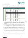
This protection function is adjusted by setting five different parameters:
www.fanox.com
42/309
Function
Description
Minimum
Step
Unit
Default
-
No
I nom
1.2
Thermal image protection function
49
Permission
-
-
Yes/No
0.10
2.40
0.01
ζ heating
3
600
1
min
3
ζ cooling
1
6
1
ζ heating
1
Alarm
20
99
1
%
80
Tap
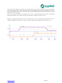
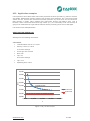
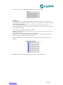
4.6.1.
Maximum
Thermal image measurement evolution graphic
On next graphic, thermal image measuremet evolution can be observed depending on applied current:
Th %
100%
75%
t
1
2
3
4
alarm
trip
We suppose that thermal image protection has and adjusted tap of 1,1 times the nominal current and
an alarm level of 75%.
www.fanox.com
43/309
Zone 1: The machine is deenergized for a long time. Therma image is 0%.
Zone 2: We supply the machine with the nominal current. Thermal image evolutions so as to get the
2
value of the thermal balance corresponding to one time the nominal current Th = (I/It) = 82%. The
time that it takes in getting the thermal balance depends on the adjusted heating constant.
Zone 3: Once reached the thermal image corresponding to the application of one time the nominal
current, we apply 1,2 times the nominal current. Therma image will evolutione so as to get the thermal
2
balance corresponding to 1,2 times the nominal current Th = (I/It) = 119%. This would occur if we had
the permission of the thermal function disabled. If the permission is disabled, 49 protection function
performs when the thermal image reachs the value of 100%. Once tripped, current is cutted and
thermal image is getting cool based on the cooling constant.
Zone 4: Before getting totally cool, nominal current is applied again and thermal balnace is reached
once passed the time determined by the heating thermal constant.
Thermal image protection alarm bit is active if the thermal image measurement is over the adjusted
alarm level.
Thermal image protection trip bit is active when the measurement of the thermal image is over 100%
and it is reset when the measurement of the thermal image is under the adjusted alarm level.
4.6.2.
Thermal image with memory
Thermal image is stored in non-volatile RAM memory periodically every second. By this way, though
the relay loses the power supply, it will keep the thermal status of the machine.
.
4.6.3.
Thermal image measurement display. Reset.
Thermal image measuremet can be displayed on Measurement menu and Counters menu.
Display is possible in Measurement menu. Display and thermal image value reset is possible in
Counters menu.
www.fanox.com
44/309
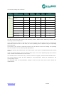
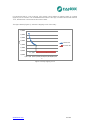
4.6.4.
Thermal protection curves
This is the thermal curve for ζ = 3 minutes.
www.fanox.com
45/309
4.7.
Function 37P. Definite-time phase undercurrent
This protection function is adjusted by setting three different parameters:
Function
Description
Minimum
Maximum
37P_1
Definite-time phase undercurrent
37P_2
Permission
Step
Unit
Default
-
-
Yes/No
-
No
Tap
0.10
30
0.01
xIB
0.50
Operating time
0.02
300.00
0.01
s
0.02
The operating time is completely independent of the operating current through the equipment, such
that should the phase current gone down the set value during the same amount of time or more than
the set one, the protection function acts (trips) and there it is not restored until the measured value of
the phase exceeds the current set point.
The function pick up occurs at 100% of the adjusted input and the dropout at 105%. The reset type is
instantaneous.
The accuracy of the “Operating time” is the set time plus a maximum of 30 ms.
4.8.
Function 59P_1 and 59P_2. Definite-time phase overvoltage
This protection function is adjusted using three parameters:
Function
Description
Minimum
Maximum
Step
Unit
Default
59P_1
Definite-time phase overvoltage
59P_2
Permission
-
-
Yes/No
-
No
Tap
4
110
1
V
75
Operating time
0.02
300.00
0.01
s
100
Reset time
0.2
1200.0
0.1
s
0.2
The operating time is completely independent from the measured phase voltage, such that if the
phase voltage exceeds the adjusted value for a period of time equal to or higher than the preestablished value, the protection function actuates (trips) and does not reset itself until the measured
phase voltage value drops below the pre-established voltage point during adjusting reset time.
The function activates at 100% of the adjusted input and deactivates at 95%. Reset is temporized and
reset time is adjusted with reset time parameter.
The accuracy of the operating time is the adjusted time ±30ms.
www.fanox.com
46/309
4.9.
Function 59N_1 and 59N_2. Definite-time neutral overvoltage
This protection function is adjusted using three parameters:
Function
Description
Minimum
Maximum
Step
Unit
Default
59N_1
Definite-time neutral overvoltage
59N_2
Permission
-
-
Yes/No
-
No
Pickup
4
110
1
V
10
Operating time
0.02
300.00
0.01
s
100
Reset time
0.2
1200.0
0.1
s
0.2
The operating time is completely independent of the measured neutral voltage, such that should the
neutral voltage exceed the set value during the same amount of time or more than the set one during
operation time, the protection function acts (trips) and there it is not restored until the measured value
of the neutral voltage drops below the voltage set point during adjusting reset time.
The function pick up occurs at 100% of the adjusted input and the dropout at 95%. The reset type is
temporized and reset time is adjusted with reset time parameter.
The accuracy of the operating time is the adjusted time ±30ms.
NB: The neutral voltage is obtained internally in the equipment, using the sum of the 3-phase voltages.
4.10. Function 27P_1 and 27P_2. Definite-time phase undervoltage
This protection function is adjusted using three parameters:
Function
Description
Minimum
Maximum
Step
Unit
Default
27P_1
Definite-time phase undervoltage
27P_2
Permission
-
-
Yes/No
-
No
Pickup
4
110
1
V
50
Operating time
0.02
300
0.01
s
100
Reset time
0.2
1200.0
0.1
s
0.2
The operating time is completely independent of the measured phase voltage, such that should the
phase voltage goes down the set value during the same amount of time or more than the set one, the
protection function acts (trips) and there it is not restored until the measured value of the phase
voltage exceeds the voltage set point during adjusting reset time.
The function pick up occurs at 100% of the adjusted input and the dropout at 105%. The reset type is
instantaneous temporized and reset time is adjusted with reset time parameter.
The accuracy of the operating time is the adjusted time ±30ms.
www.fanox.com
47/309
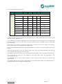
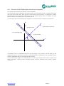
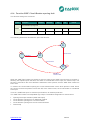
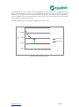
4.11. Function 32/40. Definite-time directional overpower
Four definite-time directional overpower units are available.
The intervention sector is defined in the following way: the characteristic angle is rotated anticlockwise
along the active power axis, which gives us the maximum torque direction. A straight line is drawn
perpendicular to this maximum torque direction at the adjusted pickup point, to establish two halfplanes to define the operating and non-operating zones.
The directional power protection function operates in accordance with the following characteristic:
Q
angulo caracteristico = 60º
ZONA OPERACION
Operating zone
Characteristic angle=60°
ZONA NO OPERACION
Non operating zone
S (Tap
function)
S (toma
función)
P
An operating zone is established based on the tap setting of the function and the setting of the
characteristic angle. The function trips if the measured power is maintained in the operating zone for
the time established using the corresponding time setting.
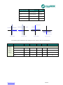
As the characteristic angle can be adjusted from 0° to 359°, we can adjust the function to obtain direct
active overpower, reverse active overpower, direct reactive overpower and reverse reactive
overpower.
www.fanox.com
48/309
Characteristic angle
Description
Address
0º
Active overpower
Direct
180º
Active overpower
Inverse
90º
Reactive overpower
Direct
270º
Reactive overpower
Inverse
characteristic angle = 90º
Q
Q
OPERATING ZONE
Q
NON OPERATING ZONE
Q
OPERATING ZONE
NON OPERATING ZONE OPERATING ZONE
S (function pikcup)
P
S (function pikcup)
P
characteristic angle = 180º
characteristic angle = 0°
(function pikcup)S
P
P
NON OPERATING ZONE
NON OPERATING ZONE
S (function pikcup)
OPERATING ZONE
characteristic angle = 270º
Direct active overpower
Inverse active overpower
Direct reactive overpower
Inverse reactive overpower
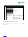
The following table establishes the settings for each function and its characteristics:
Function
Description
Minimum
Maximum
Step
Unit
Default
32_1
Definite-time directional overpower
32_2
Permission
-
-
Yes/No
-
No
32_3
Tap
0
10000
1
VA
10
32_4
Characteristic angle
0
359
1
º
0
0.02
300.00
0.01
s
100
Time
www.fanox.com
49/309
4.12. Function 81O/U. Overfrequency and underfrecuency protection
There are four protection units of the variation in frequency. Each one of them has an adjustment
which determines whether the unit acts as overfrequency or underfrequency. The reaction time of the
unit is determined by the set operating time.
In case the unit acts like overfrequency, activation of the function occurs at 100% frequency level set
and is reset when the measured frequency is 50 mHz lower than set start level.
If the unit is set as underfrequency, activation of the function occurs at 100% frequency level set and is
reset when the measured frequency is 50 mHz higher than set start level.
The reset is temporized and the reset time is determined by the reset time setting.
Accuracy of operating time and reset time is adjusted time plus a maximum of 30ms.
The frequency measurement is done from the voltage of phase B. It takes a minimum of 30 volts at
this stage for 81 functions to be operational. If the measured phase voltage is less than 30 volts, it
activates a state bit indicating function blocked. When the frequency measurement is again valid,
function begins in the start state with all bits and counters reset.
This protection function is adjusted by setting five different parameters:
Function
Description
Minimum
Maximum
Step
Unit
Default
81_1
Overfrequency or Underfrequency
81_2
Permission
-
-
Yes/No
-
No
81_3
Type
-
-
(1*)
-
Underfrequency
81_4
Activation level
45.00
65.00
0.01
Hz
55
Operating time
0.02
300.00
0.01
s
100
Reset time
0.2
1200.0
0,1
s
0.2
(1*) Overfrequency or Underfrequency
www.fanox.com
50/309
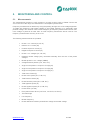
4.13. Function 52. Circuit Breaker monitoring
This function allows the status of the circuit breaker to be monitored and preventive maintenance to be
performed, for which the following parameters need to be configured:
Function
52
Description
Minimum
Maximum
Step
Unit
Default
Excess of number of openings
1
10,000
1
-
10
Maximum accumulated amperes
1
100,000
1
M(A²)
1,000
Opening time
0.02
300.00
0.01
s
0.10
Closing time
0.02
300.00
0.01
s
0.10
1
10,000
1
-
3
1.00
300.00
0.01
min
9.00
Circuit breaker monitoring
Excess of repetitive number of
openings
Time for excess of repetitive
number of openings
NOTE: The “Maximum accumulated amperes” adjustment units are M(A²) (square mega amperes)
whilst the “Accumulated amperes counter” units are K(A²) (square kilo amperes).
It is also necessary to assign the logical inputs 52a and/or 52b to a physical input.
This function provides information about the circuit breaker status and if any maintenance alarm has
been activated.
www.fanox.com
51/309
The following statuses are associated with this function:
Function
52
Status
Description
Breaker monitoring
Start
Error
Open
Opening Time
Energized/Deenergized
These are the different statuses of the circuit breaker
Opening Failure
automatic control
Close
Closing Time
Closing Failure
Configured number of openings
exceeded
Activated if the counter that measures the number
ofopenings exceeds the "Maximum number of openings"
setting
Configured accumulated amperes
exceeded
Activated if the accumulated amps counter exceeds
"Maximum accumulated amps" setting
Repetitive trips
Activated the number of openings exceeds the setting in
"Maximum repeated openings" for the time set in "Time of
maximum repeated openings"
The way that the circuit breaker is monitored becomes more or less complex depending on whether it
is fitted with one breaker contact (52a or 52b) or both (52a and 52b).
If only the circuit breaker 52a contact is available, it should be wired to the corresponding physical
input. This physical input is then assigned to the "52a Input” logical input. The 52b logical input is
calculated internally as the negative of 52a. The circuit breaker performance is shown in the following
finite state machine:
www.fanox.com
52/309
If only the circuit breaker 52b contact is available, it should be wired to the corresponding physical
input. This physical input is then assigned to the "52b Input” logical input. The 52a logical input is
calculated internally as the negative of 52b. The circuit breaker performance is shown in the following
finite state machine:
www.fanox.com
53/309
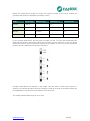
If both of the circuit breaker contacts 52a and 52b are available, they should be wired to the two
physical inputs. These physical inputs are then assigned to the corresponding logical inputs: the circuit
breaker 52a contact to the "52a Input" logical input, and the circuit breaker 52b contact to the "52b
Input" logical input. The circuit breaker's automaton is considered as having eight statuses: start,
open, closed, error, opening time, opening fault, closing time and closing fault.
The circuit breaker performance is shown in the following finite state machine:
52a & 52b
52a & 52b
Inicio
52a & 52b
ABIERTO
52a & 52b
52a & 52b
ERROR
52a & 52b
52a & 52b
CERRADO
52a & 52b
52a & 52b
Fallo
Cierre
Fallo
apertura
52a & 52b
52a & 52b
52a & 52b
+
52a & 52b
TimeOut
TimeOut
52a & 52b
+
52a & 52b
Tiempo
apertura
Tiempo
cierre
4.13.1. Circuit Breaker opening and closing commands
The circuit breaker opening and closing commands are implemented. These commands can be
executed from the HMI commands menu or using the HMI’s specific keypad or from local or remote
communications. In order that the command related to the key can run, the menu must be in standby
mode.
To carry out commands from the remote communications (ModBus or IEC60870-5-103 for non
compact SILB and ModBus, IEC60870-5-103, IEC61850 or DNP 3.0 for compact SILB) the equipment
must be in TELECONTROL mode. (see the telecontrol section).
For the commands to have an effect, they should be assigned to the corresponding outputs. The
"Open circuit breaker" and "Close circuit breaker" bits are assigned to their corresponding outputs in
the "CONTROL" status group in the status menu.
www.fanox.com
54/309
4.13.2. Counter to register the number of openings
The SIL-B equipment is fitted with a counter that registers the number of times the circuit breaker
opens.
This counter is associated with the "Excess of number of openings" setting. When the number of
openings exceeds this preset value, the "Maximum number of openings" status is activated and its
corresponding event is generated.
This counter reading can be set to any value within its range from the HMI or by using
communications.
2
4.13.3. Accumulated amps counter: I t
An accumulated amps counter is also fitted. This counter accumulates the amps that are cleared by
the circuit breaker by opening.
When the circuit breaker opens, the maximum number of primary amps in any of the phases is
detected. This reading is squared and divided by 1000 and then rescaled to KA and accumulated. If
the current detected in the opening is less than the rated current, the rated current value is used for
the accumulation.
It is used in conjunction with the counter of the number of openings, to measure the circuit breaker
aging process.
Since primary amps are being accumulated, it is essential to correctly adjust the phase CT
transformation ratio.
The "Maximum accumulated amps" setting is associated with this counter. When the number of
accumulated amps exceeds this preset value, the "Maximum accumulated amps" status is activated
and its corresponding event is generated.
The value of this counter can be started at any value within its range from the hmi or from
communications, if this protection is fitted on a circuit breaker with a previous service life.
This alarm can be replaced by modifying the Accumulated Amps counter.
The display unit shall be KA² (square kilo amperes).
4.13.4. Maximum openings in a time window
As well as counting the number of times the circuit breaker opens, the SIL-B equipment sets up a time
window and the maximum number of openings allowed during this time. Both parameters can be
adjusted.
When this number is exceeded, the " Excess of repetitive number of openings " status is activated and
its corresponding event is generated.
This alarm resets itself, when the corresponding time is exceeded with less trips than those indicated.
www.fanox.com
55/309
4.14. Function 50BF. Circuit Breaker opening fault
This function settings are as follows:
Function
Description
Minimum
Maximum
Step
Unit
Default
-
-
Yes/No
-
No
0.02
1.00
0.01
s
0.2
Circuit breaker opening fault
50BF
Permission
Opening fault time
The following automaton describes the open fault function:
Trip
50BF
t>
Imax< 8% Inominal
Run
INIT_50BF = 1
Pickup
50BF
Imax< 8% Inominal
Reset
50BF
INIT_50BF = 0
Imax< 8% Inominal
When the “50BF Start” status is activated, a switch is made to the "50BF" start and time is counted. If,
following the adjusted open fault time, the switch is not detected to have open, the function trips. The
function is reset when the circuit breaker is detected to have opened, and the “50BF Start” status has
been reset.
To monitor the circuit breaker opening the current measurement via the three phases is used. When
the current via the three phases is less than 8% of the rated current, the circuit breaker is considered
to be open.
There is a “50BF start input” to start the open fault from an external protection.
The “50BF Start” status is an adjustable logic output. The default configuration is shown below:
Opening fault input activation (50BF start input)
Circuit breaker opening from an HMI/local modbus
Circuit breaker opening from a remote modbus
Circuit breaker opening from remote communications
General trip
www.fanox.com
56/309
4.15. Function 74TCS. Trip circuit supervision
This function permits monitoring of the circuit breaker trip circuits. This is performed in two ways:
Verifying there is a trip voltage.
Verifying the continuity of the trip circuit, in both circuit breaker position, both open and closed.
For the first monitoring procedure, a digital input is fitted, with stricter activation than the other inputs.
For the second monitoring procedure, a weak current is injected which must flow from the relay to the
circuit breaker trip coil. Finally, to avoid spurious components this must be appropriately time delayed.
This function settings are as follows:
Function
Description
Minimum
Maximum
Step
Unit
Default
Trip circuit supervision
74TCS
Permission
-
-
Yes/No
-
No
Time delay
0.02
300.00
0.01
s
2.00
The schematic for this criteria is as follows:
Circuit A superv ision
Circuit B superv ision
Function permission
T
Control v oltage
T 0
T_UP
www.fanox.com
57/309
4.16. Function 79. Autorecloser
The reclosing function recloses the circuit breaker after a fault. It has a five reclosing capacity,
following which the unit shall be Locked or in “Lockout” mode.
The reclose device can be permitted or prohibited, depending on whether or not this function is
required. Prohibited must not be confused with locked. Prohibited means that the recloser shall never
be in operation, regardless of the controls performed on it. A locked recloser means that the recloser is
not operative, but either because it has reached the end of the reclosing cycle, or a fault has been
detected, or someone has performed a control procedure on it.
There is a final permission which serves to indicate, that recloser must wait a period of time before
closure. In this time, there is usually an external condition, such as closure synchronism, and this
condition is defined by an external input.
Each reclosing cycle has its own specific operation time that can be set. Apart from these times, a
further three times must be set:
Hold time. This is the time the reclosing device waits for an external condition for closure.
Reset time. This is the Hold time for the recloser for a final closure. If during this time, there is
another trip, the recloser count will increase.
Final opening time The is the time used by the recloser to declare that the circuit breaker is finally
open. In this case, the recloser understands that the opening was manual or via remote control,
and no reclosing is necessary. On exceeding this time, the recloser shall switch to locked mode.
The reclosing function settings are shown below:
Function
Description
Minimum
Maximum
Step
Unit
Default
Permission
-
-
Yes/No
-
No
Hold permission
-
-
Yes/No
-
No
Number of shots
1
5
1
-
3
Reclose 1 time
0.02
300.00
0.01
s
0.30
Reclose 2 time
0.02
300.00
0.01
s
3.00
Reclose 3 time
0.02
300.00
0.01
s
180.00
Reclose 4 time
0.02
300.00
0.01
s
180.00
Reclose 5 time
0.02
300.00
0.01
s
180.00
Hold time
0.02
300.00
0.01
s
10.00
Reset time
0.02
300.00
0.01
s
10.00
Final Opening Time
0.02
300.00
0.01
s
10.00
Reclosing device
79
www.fanox.com
58/309
It must be possible to lock the recloser, particularly is maintenance tasks are carried out on the
substation. To this end there are various SIL-B locking and unlocking possibilities:
From the HMI. There is a specific key marked 79, plus a specific signal led, allowing recloser
operation, locking or unlocking it. In order that the command related to the key can run, the menu
must be in standby mode.
From the HMI. This command can be executed from the control menu.
From two pulse inputs. If the substation is equipped with a conventional remote control, two
pulse outputs are usually assigned, where one locks the recloser and the other locks it.
Via protocol. This is performed via any means of communication. This is carried out as if it were a
control, and the normal conditions of any control must be met. For example, if we are operating
from the HMI, it is understood that the relay is in local mode, whereby if a Lock/Unlock command
is received via remote control this shall be ignored.
From a level input. In this case the recloser monitors the status of the input. This may be of use if
the company has a handle with a key.
In the first four cases, the equipment stores the lock situation in the non-volatile memory, as the last
control must be know for a possible re-start.
The auto-recloser´s start up is shown in the following figure: There are two stable conditions here,
Standby and Lockout, the other conditions are transient.
www.fanox.com
59/309
52 Close
Manual
Open
Time
STANDBY
52 Open
79 Init Input
Reclose Init
+
Configurable Init
N=N+1
TimeOut
Reclose
Time
N > Max Number Shots
TimeOut
52
Is Open?
52 Close
Wait Reclose Condition
No Hold Time
Hold
Time
TimeOut
Reclose Condition Input
Reclose Init
Close
Time
TimeOut
TimeOut
52 Close
Reset
Time
52 Close & 79 Unblock Command
TimeOut
Safety
Time
LOCKOUT
52 Open
79 Block Input + 79 Block Command
www.fanox.com
60/309
On standby. The recloser can leave this mode via three conditions:
Recloser lock, via a command.
Manual or remote control opening of the circuit breaker. In this situation it shall wait the final
opening of the same, and then it shall switch to lock mode.
Circuit breaker trip. This shall start the reclosing cycles. This start may arise either from the trip
itself, or from an external input if external protection is fitted.
When locked. The recloser shall switch from this condition as a result of two different conditions:
Manual or remote control closing of the circuit breaker. In this case it shall switch to safety time. If,
during this time, there is a trip, it shall revert to Lockout.
Unlocking of the recloser. Via a command.
Of all the remaining conditions, it is interesting to know that the recloser sends a closure command
whilst it is in the Close Time condition, and for this reason if you wish to program an output on said
command, the output must be set to the 79TmpCierre bit.
The “79 Start” status is an adjustable logical output. The default configuration is shown below:
Activation of the recloser start input (“79 start input”)
67P_1 trip
67N_1 trip
46 trip
www.fanox.com
61/309
By default, in this configuration, the recloser is not activated by the operations of functions 50P_1,
50P_2, 50N_1, 50N_2 and 50BF.
4.16.1. Counter to record the number of reclosings
The SIL-B equipment is fitted with a counter that records the number of reclosings.
4.17. Function 25. Synchronism protection function
The synchro-check function is designed to give a time window in which the voltage in both sides of the
switch are in sync. The conditions that the voltage of both ends of the switchgear must have to assert
that there is synchronization are:
-
Same module
Same phase
Same frequency
Associated with the function, we have a line voltage and bar voltage monitoring unit, which will define
the state of the line and the bar, being able to give the following combinations:
-
LLLB (Live Line - Live Bar), live line - live bar
LLDB (Live Line - Dead Bar), live line - dead bus
DLLB (Death Line - Live Bar), dead line - live bar
DLDB (Death Line - Dead Bar), dead line - dead bus
The settings associated with this unit voltage monitoring are:
Function
25
Description
Minimum
Maximum
Step
Unit
Default
Synchronism. Line and bar voltage supervision unit
Live line voltage
30
110
0,1
V
50
Dead line voltage
4
110
0,1
V
30
Live bar voltage
30
110
0, 1
V
50
Dead line voltage
4
110
0, 1
V
30
0.02
300.00
0.01
s
0.02
Voltage supervision time
A time during which it is confirmed that the end is dead or live to be sure it is not a temporary situation
is specified
www.fanox.com
62/309
According to the live or dead state of the line and the bar,four permissions exist that allow or not to
close the line over the bar:
Function
25
Description
Minimum
Maximum
Step
Unit
Default
Synchronism. Operation permissions
Permission LLLB
-
-
-
Yes/No
No
Permission LLDB
-
-
-
Yes/No
No
Permission DLLB
-
-
-
Yes/No
No
Permission DLDB
-
-
-
Yes/No
No
In case the line or bar or both are dead (LLDB, DLLB, DLDB situations) permission to close is only
determined by the setting of permission. It is not necessary the synchronism to close the switchgear.
When the line and the bar are alive is the time to check the conditions of voltage magnitude, phase
difference and frequency difference between line voltage and bar voltage to allow the closure. It is
verified that these conditions of voltage magnitude, phase difference and frequency difference is
maintained over a set time, to verify that it is not a temporary situation.
Function
25
Description
Minimum
Maximum
Step
Unit
Default
4
110
0,1
V
0
359
1
°
10
Line-Bar frequency
difference
0.02
0,50
0.01
Hz
0.02
Synchronism time
0.02
300
0.01
s
0.02
Synchronism. Synchronism algorithm
Line-Bar voltage
difference
Line-Bar phase
difference
If these conditions of synchronism are mantains during synchronism time, we will have switch close
permission.
www.fanox.com
63/309
15
The sync function generates the following bits:
Sincronismo
25
LLLB: Live line, live bar
LLDB: Live line, dead bar
DLLB: Dead line, live bar
DLDB: Dead line, dead bar
Close permission
LLLB, LLDB, DLDB and DLLB bits indicate the status of the line and the bar regardless of the
operation permissions statuses.
The closing permission signal remains active while the conditions of synchronism are accomplished. In
any case, once the signal is activated, it remains a minimum of 150 ms, in case synchronism
conditions disappear.
The following schema describes a logical diagram of the algorithm:
25 block input
52 Open
DLLB
DLLB permission
Line voltage and bar voltage supervision unit
LLDB
25 closure permission
LLDB permission
DLDB
DLDB permission
LLLB
LLLB permision
| Vline | - | Vbar | < Vset
| Qline- Qbar | < Qset
T
0
| fline - fbar| < fset
www.fanox.com
64/309
The line and bar voltage monitoring unit sets the dead or alive state of the line and bar. Transitions
from dead to live and vice versa are timed with a user adjustable time. During the transition the line or
bar is in undefined state. At such moments, as seen in the logical diagram of the algorithm, the closing
permission is not activated.
Once the voltage exceeds the live state level, a timer is started during which we turn to undefined
state until the timer ends. At this moment, indicates the live status of the bar or line.
When the voltage falls below the level of dead state, a timer is started during which we turn to
undefined state until the timer ends. At this moment, indicates the dead status of the bar or line.
www.fanox.com
65/309
4.17.1. Synchronism (25) and recloser (79)
For the circuit breaker is closed when recloser command (79) is permited, it is necessary to achieve
sync conditions. Only when these sync conditions are achieve, the recloser has the permission to do
the closure of circuit breaker. This is, for the recloser close is supervised by the closing permission
given by sync function, it is necessary to set the "Permission of closure" state of sync function to the
logical input "79 permission input".
www.fanox.com
66/309
Synchronism function (25) associated to recloser function (79)
If the parameter “Hold permission” of 79 function is prohibited any external condition will be considered
and 79 function will work normally without considering synchronism.
If “Hold permission” of 79 function is enable and it is associated with “ Permission of closure” of 25
function, could be occur:
1. If permissions LLLB, DLLB, LLDB y DLDB of 25 function are all prohibited, after tripping because
of a fault, circuit breaker never will be reclosed because “Permission of closure” bit of 25 function
will never be activated. After time adjusted in hold time, 79 function will go to LOCKOUT status.
2. If permissions LLLB, DLLB, LLDB y DLDB of 25 function are all enable, it will be distinguished the
following cases:
a) If line, bar or both of them are dead, the circuit breaker will be always reclosed, because
“Permission of closure” only depends on corresponding permission adjustment, and it is not
necessary synchronism to get the circuit breaker reclose. .
b) If both, line and bar, are alive it will be necessary to get the reclose of the circuit breaker,
not only LLLB permission to be enable either to check synchronism. If LLLB permission is
enable but synchronism conditions do not verify the reclose will not occur and vice versa.
www.fanox.com
67/309
4.17.2. Syncronism (25) and manual closure (52)
For the manual closure of 52 function is supervised by the closing permission given by sync function, it
is necessary to associate the "Permission of closure " status of sync function to the logical input "52
Permission of closure "
www.fanox.com
68/309
Synchronism function (25) associated to manual closure (52)
If “ 52 permission of closure” is associated with “Permission of closure” of synchronism function, could
be occur:
1. If permissions LLLB, DLLB, LLDB y DLDB of 25 function are all prohibited, the closure of the
circuit breaker does not occur. In spite of “close breaker” command being execute by
communication or pressing the key in the relay, circuit breaker never will close
2. If LLLB, DLDB, DLLB, y LLDB permissions of 25 function are enable it can be distinguished some
possibilities:.
a) If line, bar or both of them are dead it will always produced the manual closure of the circuit
breaker because “52 permission of closure” only depends on corresponding permission
adjustment, and it is not necessary synchronism to get the circuit breaker closure.
b) If both, line and bar, are alive it will be necessary to get the manual closure of the circuit
breaker, not only LLLB permission to be enable either to check synchronism. If LLLB
permission is enable but synchronism conditions do not verify, after pressing CLOSE
BREAKER command, circuit breaker closure does not occur and vice versa.
4.18. Cold Load Pickup
This unit is used to prevent undesired operations of the overcurrent functions in the cases where,
when the line is deenergised, all the loads enter at the same time.
This function settings are as follows:
Group
Description
Minimum
Maximum
Step
Unit
Default
Permission
-
-
Yes/No
-
No
50P_1 Multiplier
1
5
0.01
-
1
50P_2 Multiplier
1
5
0.01
-
1
67P_1 Multiplier
1
5
0.01
-
1
67P_2 Multiplier
1
5
0.01
1
50N_1 Multiplier
1
5
0.01
1
50N_2 Multiplier
1
5
0.01
-
1
67N_1 Multiplier
1
5
0.01
-
1
67N_2 Multiplier
1
5
0.01
-
1
CLP switch time
1
18000
0.01
s
15
CLP duration
1
18000
0.01
s
15
Cold Load Pickup
CLP
The two time parameters have the following meaning:
www.fanox.com
69/309
CLP switch time: If the circuit has been open for less time than that set in this parameter, the Cold
Load Pickup is not activated. When this time is exceeded, the overcurrent functions are multiplied
by the indicated constant.
CLP duration: Time from the passage of current in which time the Multiplier is applied to the
overcurrent functions tap. After this time, the relay returns to the adjusted taps.
There is a conditioner in the multiplier. The maximum protection functions are located in their tap. This
maximum can never be exceeded, regardless of the adjusted tap in the protection function and the
Cold Load function multiplier.
The function operated according to the following automaton. The automaton consists of six statuses,
three of them with normal adjustment, and the other three with the extended adjustments. During
transit, the settings are maintained according to where they come from.
The current level is used to determine the change, more than the circuit breaker situation. If the
current less than 10% of the rated level, it is understood that the line is open, with an extremely low
usage level (operating at night, or on weekends). In one case or the other CLP must start.
The relay normally operates with the settings in their active table. When the circuit breaker opens, a
timer starts. The remote control could activate circuit breaker closure, and also, if a permanent fault
occurs the circuit breaker may open again. To prevent the increase counter from resetting there is a
condition which reduces the activation time from where it was. If the counter exceeds its limit, a switch
is made to Cold Load. On the contrary, if the counter reaches zero, a switch is made to the standby
condition. This mechanism is identical in Cold Load reset.
Time to deactivate
In > 10%
Time to deactivate
CLP
incrementing
CLP
decrementing
In < 10%
Time Out
Time Out
In > 10%
Cold Load
Pickup
Run
In < 10%
Time Out
Time Out
In > 10%
Time to activate
CLP
decrementing
www.fanox.com
Time to activate
CLP
incrementing
In < 10%
70/309
4.19. General settings
General settings establish some parameters that are necessary for the relay to operate. These
settings are defined as general because they affect the entire relay, and as a result they are not
subject to a change of table.
Function
Description
Minimum
Maximum
Step
Unit
Default
Equipment identifier
-
-
-
-
“www.fanox.com”
Transformation ratio of
the phase CTs
1
2000
1
-
100
Transformation ratio of
the neutral CTs
1
2000
1
-
100
Transformation ratio of
the VTs
1
2000
1
-
100
Frequency
-
-
60/50
Hz
50
Language
-
-
-
-
English
Active table
1
3
1
-
1
Modbus address
1
254
1
-
2
Modbus baudrate
4800
38400
-
bauds
19200
General settings
Communications
1. Equipment identifier. It is an ASCII text used to identify the equipment. Protection equipments are
normally associated with a specific line or position, and this setting is used for said identification. It
is important to fill this field in correctly, as the events and oscillography data is accompanied by
this information.
2. The phase and neutral CT transformation ratio setting allows the measurements of the primary
values from the protection transformer to be viewed. Given that the SIL-B is a pass-through
module that allows several turns to be made, the number of turns must be taken into account
when the transformation ratios are adjusted.
3. Frequency. Displays the equipment’s frequency.If the device is a non compact SILB the frequency
is selected using an internal selector in the equipment, which can be accessed by removing the
rear selector access cover. If the device is a compact SILB it is not possible to change the
frequency because this parameter is imposed by the model.
4. Language. The SIL equipment has the capacity to display messages in four languages, one of
which is English in all of them. Please see the list of models to find out about available languages.
5. Active Table: see Settings
6. Communication settings (address and baudrate ModBus RTU (RS485): see Communications
www.fanox.com
71/309
The rest of the settings are grouped by functions to facilitate their operation. These groups are subject
to tables.
The equipment identifier setting can only be adjusted through communications.
The frequency setting is read-only. The frequency is selected using an internal selector in the
equipment, which can be accessed by removing the rear selector access cover.
The rest of the settings can be modified equally from the HMI or through communications.
Any change to settings involves resetting the functions, regardless if they are active or not.
4.20. Settings Group
There are three group settings tables and one general table. The settings table which is active at a
specific moment can be modified in two ways:
Changing the active Table settings. In the general group there is a setting which establishes which
table is active.
By means of two inputs. To this end four possibilities are defined.
00
This situation is governed by the active table settings.
01
Table 1
10
Table 2
11
Table 3
In the zero position the active item is defined by the active table settings defined in the general group.
Regarding other options, regardless of that established by the settings, the inputs prevail over the
settings.
If the use of both inputs is not required, then one can be used, but depending on which is used,
operation can be done with table 1 or table 2.
www.fanox.com
72/309
4.21. IEC 60255-151 Curves
The IEC curves follow the following mathematical equation:
t
A D
B D K
VP Q
Where:
V
I
I adjusted
And we have the following curves:
Inverse Curve
Very Inverse Curve
Extremely Inverse Curve
Which relate to the parameters figuring in the following table:
Parameters
A
P
Q
B
K
Ext. Inverse
80
2
1
0
0
Very Inverse
13.5
1
1
0
0
Inverse
0.14
0.02
1
0
0
The curve can mode from its axis using the D time selection device, which the user can adjust.
Iadjusted is the initial operating current, set by the user.
www.fanox.com
73/309
IEC Inverse
1000,000
100,000
Dial 0,05
Dial 0,1
Dial 0,2
10,000
Dial 0,3
Dial 0,4
t (s)
Dial 0,5
Dial 0,6
Dial 0,7
Dial 0,8
Dial 0,9
1,000
Dial 1,0
Dial 1,1
Dial 1,2
0,100
0,010
1,0
10,0
100,0
I/It
www.fanox.com
74/309
IEC Very Inverse
1000,000
100,000
Dial
0.05
Dial 0,1
10,000
Dial 0,2
Dial 0,3
t (s)
Dial 0,4
Dial 0,5
Dial 0,6
Dial 0,7
1,000
Dial 0,8
Dial 0,9
0,100
0,010
1,0
10,0
100,0
I/It
www.fanox.com
75/309
IEC Extremely Inverse
1000,000
100,000
Dial
0.05
Dial
0,1
Dial
0,2
Dial
0,3
Dial
0,4
Dial
0,5
Dial
0,6
Dial
0,7
Dial
0,8
Dial
0,9
Dial
1,0
Dial
1,1
t (s)
10,000
1,000
0,100
0,010
1,0
10,0
100,0
I/It
www.fanox.com
76/309
4.22. ANSI-IEEE Curves
The ANSI curves follow the following mathematical equation:
A
t TD P B
V 1
Where:
V
I
I adjusted
And we have the following curves:
Inverse Curve
Very Inverse Curve
Extremely Inverse Curve
Which relate to the parameters figuring in the following table:
Parameters
A
P
B
Ext. Inverse
28.2
2
0.1217
Very Inverse
19.61
2
0.491
Inverse
0.0515
0.02
0.114
The curve can move from its axis using the TD time selection device, which the user can adjust.
Iadjusted is the initial operating current, set by the user.
www.fanox.com
77/309
ANSI-IEEE Inverse
1000,000
100,000
Dial
0,05
Dial 0,1
10,000
Dial 0,2
t (s)
Dial 0,5
Dial 0,8
Dial 1
Dial 1,2
1,000
0,100
0,010
1,0
10,0
100,0
I/It
www.fanox.com
78/309
ANSI-IEEE Very Inverse
1000,000
100,000
Dial
0,05
Dial 0,1
10,000
Dial 0,2
t (s)
Dial 0,5
Dial 0,8
Dial 1
Dial 1,2
Dial 1,5
1,000
Dial 2
0,100
0,010
1,0
10,0
100,0
I/It
www.fanox.com
79/309
ANSI-IEEE Extremely Inverse
1000,000
100,000
Dial
0,05
Dial 0,1
10,000
Dial 0,2
Dial 0,5
t (s)
Dial 0,8
Dial 1
Dial 1,2
Dial 1,5
Dial 2
1,000
Dial 2,2
0,100
0,010
1,0
10,0
100,0
I/It
www.fanox.com
80/309
4.23. Application examples
It is important to know that if both overcurrent protection functions (50 and 51), phase or neutral,
are enable, definite time function (function 50) must be more restrictive. So, if overcurrent fault
values are low, inverse time overcurrent function (function 51) must work, and if overcurrent
fault reaches a certain value, definite time overcurrent function will always work. This is
because, when overcurrent fault reach high values (I>>), it is necessary to be sure that trip is
going to be instantaneous to get that the element we are protecting, does not be damaged.
It is shown somo examples below:
APPLICATION EXAMPLE 1
Starting from the following information:
Line details:
Transformation ratio of CT =100/1
Primary current: Ip=100 A
51 function settings
Curve type: IEC Inverse
Dial: 0.05
Tap: 1xIn
50 function settings
Tap: 11xIn
Operating time: 0.05 s
0,3500
0,3000
t (s)
0,2500
0,2000
0,1500
11,0000; 0,1425
Function 51
0,1000
Function 50
0,0500
0,0000
0,0000
10,0000
20,0000
30,0000
40,0000
I
Figure 1. 50 y 51 IEC Inverse
www.fanox.com
81/309
If overcurrent fault is 11xIn=1100 Ap, IEC inverse curve defines a tripping value of 0.1425s
(Figure1) for 51 function. It is considered that this time is too high, so when current fault reaches
11xIn, definite time overcurrent function will be work.
The figure below (Figure 2), shows the tripping curve of the relay:
0,3500
0,3000
t (s)
0,2500
0,2000
Function 51
0,1500
Function 50
0,1000
0,0500
11; 0,05
0,0000
0,00 4,00 8,00 12,00 16,00 20,00 24,00 28,00 32,00
I
Figure 2. Relay tripping curve
www.fanox.com
82/309
APPLICATION EXAMPLE 2:
Starting from the following information:
Line details:
Transformation ratio of CT =500/1
Primary current: Ip=500 A
51 function settings
Curve type: ANSI Extremely Inverse
Dial: 2.20
Tap: 1xIn
50 function settings
Tap: 14xIn
Operating time: 0.1 s
25,000
20,000
Function 51
t (s)
15,000
Function 50
10,000
5,000
24; 0,376
0,000
0
5
10
15
20
I
25
30
35
40
Figure 3. 50 y 51 ANSI Extremely Inverse
www.fanox.com
83/309
If overcurrent fault is 24xIn=12000 Ap, ANSI Extremely inverse curve defines a tripping value of
0.376 s (Figure 3) for 51 function. It is considered that this time is too high, so when current fault
reaches 24xIn, definite time overcurrent function will be work. 50 function tap is adjusted at
14xIn so definite time overcurrent function will trip when current fault is higher than 14xIn (50
function does not wait to reach 24xIn)
The figure below (Figure 4), shows the tripping curve of the relay:
100,000
t (s)
10,000
1,000
Function 51
Function 50
0,100
14; 0,1
0,010
0
5
10
15
20
25
30
35
I
Figure 4. Relay tripping curve
www.fanox.com
84/309
APPLICATION EXAMPLE 3:
In this example it is explained what occurs when it is selected in curve type parameter
“DEFINITE TIME”. In this case, 51 function works as 50 function.
Starting from the following information
Line details:
Transformation ratio of CT =100/1
Primary current: Ip=100 A
51 function settings
Curve type: Definite time
Tap 1xIn
Operating time: 5 s
50 function settings
Tap: 15xIn
Operating time: 1 s
6
5
15; 5
t (s)
4
3
Function51 as function 50
2
Function 50
1
0
0
20
40
60
I
Figure 5. Function 51 (as 50) and function 50.
www.fanox.com
85/309
If overcurrent fault is 15xIn=1500 Ap, Definite time curve defines a tripping value of 5 s (Figure
5) for 51 function. It is considered that this time is too high, so when current fault reaches 15xI n,
definite time overcurrent function will be work function 50).
The figure below (Figure 6), shows the tripping curve of the relay:
6
5
t (s)
4
3
Function 51 as function 50
2
Function 50
1
15; 1
0
0
10
20
30
40
50
60
I
Figure 6. Relay tripping curve
www.fanox.com
86/309
5.
MONITORING AND CONTROL
5.1.
Measurements
The measurement precision is ±2% precision in a band covering ±20% of Rated Current and
±4% in the rest of the range of measurements. 16 samples/cycle are taken.
Frequency measurement is obtained by using the passing through zero of the voltage algorithm.
To obtain line frequency and busbar voltage to get busbar frequency it is specifically used
phase B voltage. The minimum value of this voltage to get frequency measurement are 30 volts.
If the voltage of phase B is lower than 30 volts frequency mesuremint will be 0.00 Hz. The
frequency measurement accuracy is ±0.01 Hz.
The following measurements are provided:
Phase r.m.s. currents (IA, IB, IC)
Neutral r.m.s. current (IN)
Positive sequence current (I1)
Negative sequence current (I2)
Phase r.m.s. voltages (VA, VB, VC)
Residual neutral voltage (VN), calculated internally from the sum of the phase
voltages.
Busbar phase B r.m.s. voltage (VBBus)
Voltage between phases (U12, U23, U31)
Angle current phase L1 respect to VL1(ang-IA)
Angle current phase L2 respect to VL1(ang-IB)
Angle current phase L3 respect to VL1(ang-IC)
Total Active Power (P)
Phase Active power (P-A, P-B, P-C)
Total Reactive Power (Q)
Phase Reactive power (Q-A, Q-B, Q-C)
Total apparent power (S)
Phase Apparent power (S-A, S-B, S-C)
Power factor (cos Phi)
Each phase Power factor (cos Phi-A, cos Phi-B, cos Phi-C)
Thermal image
Line frequency
Busbar frequency
Phase difference between phase B line voltage and busbar voltage
www.fanox.com
87/309
Below the measurement ranges for phase and neutral currents for the SIL-B models are
provided; said values are defined as secondary current:
Model
Phase range
Neutral range
Rated phase I
Rated neutral I
SIL-B5*
1-150 A
*
5A
*
SIL-B1*
0.2-30 A
*
1A
*
SIL-B*5
*
1-150 A
*
5A
SIL-B*1
*
0.2-30 A
*
1A
In non compact SILB device, the rear parts of models 5 A and 1 A of the SIL-B equipment are
fitted with the following switches to select the secondary current. Obviously, in the 5 A phase
models the phase A, B and C switches must be set to position /5. In the 1 A phase models the
phase A, B and C switches must be set to position /1.
Compact SILB devices will depend on the model. They will have a rated current equal to 1
Ampere or 5 Amperes and they will have a frequency equal to 50 or 60 Hz, but these values are
not adjustable by user (there are not switches in the rear part).
The voltage measurement range is 4V to 130V.
www.fanox.com
88/309
5.2.
Counters
The following counters are provided:
1. Positive active energy
2. Negative active energy
3. Positive reactive energy
4. Negative reactive energy
5. Number of openings of the circuit breaker
6. Amperes accumulated (l2t) during the openings of the circuit breaker
7. Number of shots
8. Thermal Image
It is possible to change tha values of the counters to a certain value, but firstly it is necessary to
insert the correct password.
5.3.
Statuses and Events
Statuses are real time information generated by the equipment. Some statuses are defined as a
level, and others, like trips, are too brief to be displayed in real time.
Group
50P_1
Status
Level1: Phase definite-time overcurrent
50P_1 Phase A pickup
50P_1 Phase B pickup
50P_1 Phase C pickup
50P_1 Pickup
50P_1 Phase A trip
50P_1 Phase B trip
50P_1 Phase C trip
50P_1 Trip
50P_2
Level2: Phase definite-time overcurrent
50P_2 Phase A pickup
50P_2 Phase B pickup
50P_2 Phase C pickup
50P_2 Pickup
50P_2 Phase A trip
www.fanox.com
89/309
50P_2 Phase B trip
50P_2 Phase C trip
50P_2 Trip
67/51/50P_1
Level1: Phase Inverse-time directional overcurrent
67P_1 Phase A pickup
67P_1 Phase B pickup
67P_1 Phase C pickup
67P_1 pickup
67P_1 Phase A trip
67P_1 Phase B trip
67P_1 Phase C trip
67P_1 Trip
67/51/50 P_2
Level 2: Phase Inverse-time directional overcurrent
67P_2 Phase A pickup
67P_2 Phase B pickup
67P_2 Phase C pickup
67P_2 pickup
67P_2 Phase A trip
67P_2 Phase B trip
67P_2 Phase C trip
67P_2 Trip
50N_1
Level1: Neutral definite-time overcurrent
50N_1 Pickup
50N_1 Trip
50N_2
Level2: Neutral definite-time overcurrent
50N_2 Pickup
50N_2 Trip
67/51/50N_1
Level1: Neutral inverse-time directional overcurrent
67N_1 S Pickup
67N_1 Trip
67/51/50N_2
www.fanox.com
Level2: Neutral inverse-time directional overcurrent
90/309
67N_2 Pickup
67N_2 Trip
46
Negative sequence inverse-time overcurrent
46 Pickup
46 Trip
49
Thermal image protection
49 Alarm
49 Trip
37P_1
Level1: Definite time undercurrent
37P_1 Phase A pickup
37P_1 Phase B pickup
37P_1 Phase C pickup
37P_1 pickup
37P_1 Phase A trip
37P_1 Phase B trip
37P_1 Phase C trip
37P_1 Trip
37P_2
Level2: Definite time undercurrent
37P_2 Phase A pickup
37P_2 Phase B pickup
37P_2 Phase C pickup
37P_2 pickup
37P_2 Phase A trip
37P_2 Phase B trip
37P_2 Phase C trip
37P_2 Trip
59P_1
Level1: Phase definite-time overvoltage
59P_1 Phase A pickup
59P_1 Phase B pickup
59P_1 Phase C pickup
59P_1 Pickup
www.fanox.com
91/309
59P_1 Phase A trip
59P_1 Phase B trip
59P_1 Phase C trip
59P_1 Trip
59P_2
Level2: Phase definite-time overvoltage
59P_2 Phase A pickup
59P_2 Phase B pickup
59P_2 Phase C pickup
59P_2 Pickup
59P_2 Phase A trip
59P_2 Phase B trip
59P_2 Phase C trip
59P_2 Trip
59N_1
Level1: Neutral definite-time overvoltage
59N_1 Pickup
59N_1 Trip
59N_2
Level2: Neutral definite-time overvoltage
59N_2 Pickup
59N_2 Trip
27P_1
Level1: Phase definite-time undervoltage
27P_1 Phase A pickup
27P_1 Phase B pickup
27P_1 Phase C pickup
27P_1 Function pickup
27P_1 Phase A trip
27P_1 Phase B trip
27P_1 Phase C trip
27P_1 Trip
27P_2
Level2: Phase definite-time undervoltage
27P_2 Phase A pickup
27P_2 Phase B pickup
www.fanox.com
92/309
27P_2 Phase C pickup
27P_2 Function pickup
27P_2 Phase A trip
27P_2 Phase B trip
27P_2 Phase C trip
27P_2 Trip
32_1
Level1: Definite-time directional overpower
32_1 Pickup
32_1 Trip
32_2
Level2: Definite-time directional overpower
32_2 Pickup
32_2 Trip
32_3
Level3: Definite-time directional overpower
32_3 Pickup
32_3 Trip
32_4
Level4: Definite-time directional overpower
32_4 Pickup
32_4 Trip
81_1
Level1: Underfrequency/Overfrequency
81_1 Pickup
81_1 Trip
81_ 1 Block
81_2
Level2: Underfrequency/Overfrequency
81_2 Pickup
81_2 Trip
81_ 2 Block
81_3
Level3: Underfrequency/Overfrequency
81_3 Pickup
81_3 Trip
81_ 3 Block
81_4
www.fanox.com
Level4: Underfrequency/Overfrequency
93/309
81_4 Pickup
81_4 Trip
81_ 4 Block
CLP
Cold Load Pickup
CLP Activation
50BF
Circuit breaker opening fault
50BF Pickup
50BF Trip
General
General states
General trip
Battery supply
50Hz network frequency
Magnetic module error
Measurement error
Ready
Protection error
Settings changed
Manual closure
Date and time synchronization
Local telecontrol
Default settings error
e2prom error
IRIG B presence
e2prom values changed
Event log error
Inputs
Logical and physical inputs
Input 52 a
Input 52 b
Locking 50P input
Locking 50N input
External trip input
www.fanox.com
94/309
Fault start
Start 79 input
Permission 79 input
Locking 79 level input
Active table input-1
Active table input-2
Lock pulse input 79
Unlock pulse input 79
50BF init
Input 1
Input 2
Input 3
Input 4
Input 5
Input 6
Input 7
Input 8
Command voltage
Continuity coil A
Continuity coil B
Outputs
Logical and physical outputs
Output 1
Output 2
Output 3
Output 4
Output 5
Output 6
Output 7
Output 8
Output 9
Output 10
www.fanox.com
95/309
Output 11
Output 12
Start 79
Start 50BF
Start fault
Close 79 permission (models with function 25)
Close 52 permission (models with function 25)
LED ON
LED 1
LED 2
LED 3
LED 4
LED 5
79
Recloser
79 Inactive
79 Reclosing time
79 Open
79 Hold time
79 Closing time
79 Reset time
79 Lock out
79 Safety time
79 Definitive opening time
25
Synchronism
LLLB: Live line, live bar
LLDB: Live line, dead bar
DLLB: Dead line, live bar
DLDB: Dead line, dead bar
Closure permission
52
Circuit breaker monitoring
52 Start
www.fanox.com
96/309
52 Error
52 Open
52 Opening time
52 Opening failure
52 Close
52 Closure time
52 Closure failure
52 Excess of openings
52 Excess of accumulated amperes
52 Excess of openings in a time window
State 52 a
State 52 b
74TCS
Trip circuit monitoring
74TCS Pickup
74TCS Activation
ModBus com
Remote ModBus
Remote communication exists
Command selection
Open breaker
Close breaker
Lock 79
Unlock 79
Remote com
Remote com
Remote communication exists
Command selection
Open breaker
Close breaker
Lock 79
Unlock 79
Local Com
Local Modbus
Local communication exists
www.fanox.com
97/309
HMI activity
Local
Command selection
Open breaker
Close breaker
Lock 79
Unlock 79
Set Remote Control to Local
Set Remote Control to Remote
In states 52 and 79, a bit has been assigned to each state of the automaton, so that the
evolution of said automatism can be seen if the oscillography has to be observed.
A brief description of the general states can be found below:
Trip: The equipment has tripped. This bit is the OR of all the trips, of any of the functions, plus
the external trip input. If a certain function should not cause a trip, it must be individually
prohibited. In the case of the external trip input, it should be just left unconfigured.
50 Hz network frequency: activates when the frequency setting is 50Hz, and deactivated when
the frequency setting is 60Hz.
The Ready bit encompasses the correct functioning of the relay and has the following logic:
Operation
Ready
Measure error
Protection error
Default settings
This bit is normally assigned to a contact that has a NC contact.
Magnetic module error: detects if there is a problem with the connection to the external
magnetic module in non compact SILB (Compact SIL B does not have external
magnetic module)
Measurement error: The self-diagnostic algorithms have detected a problem in the
measurement block.
Protection error: The self-diagnostic algorithms have detected a problem in the
measurement block.
Setting change: Activates when a change is made to the settings.
Date-time setting: Activates when the date-time is synchronized.
www.fanox.com
98/309
Local: the sum of the "HMI activity" and "Local communication" bits in the "Local
communication" state group
Default settings: the equipment has its default settings, not executing the trip.
Eeprom error: The self-diagnostic algorithms have detected a problem in the eeprom
memory, which contains the settings.
Eeprom change: activates when the settings or configuration are changed. The
difference between this and the setting change is that this indication includes
configuration changes, which are also stored in said memory.
Error events: The self-diagnostic algorithms have detected a corrupt even in the circular
buffer. This bit is reset by deleting the events (from the HMI or through
communications)
HMI activity: this state is active if any keys have been pressed in the last fifteen
minutes. Pressing a key assumes that the relay is set to local mode.
Remote Control to Local: whether or not the remote control is activated
Some states have an associated event, which is a log of the change that occurs in the state.
Some states have one associated activation event, and other states have two associated
events: activation and reset. These events are saved in a buffer with a capacity for up to 1000
events, and a time stamp precision of one millisecond.
Events can be viewed on the HMI and through communications. Reading the log does not
delete it; it remains stored in the equipment. To clear the events from the HMI, navigate to the
events menu and press and hold the "RESET" key until the number of events reads "1" and
corresponds to "Deleted events". Use the corresponding "delete events" command to delete the
events from communications.
Events have the following structure:
Identifier
Unique event identifier: e.g.: 51_1.4 = PICKUP OF 67P_1
Value
ON(Activated) /OFF(Deactivated): events are generated for the activation and the deactivation
Year
Month
Day
Time
Minutes
Seconds
Milliseconds
www.fanox.com
99/309
The following list contains all the states of the equipment and their associated events:
Group
Status
Cause
Associated measurement
50P_1 Phase A Pickup
Activation/Deactivation
Phase A current
50P_1 Phase B Pickup
Activation/Deactivation
Phase B current
50P_1 Phase C Pickup
Activation/Deactivation
Phase C current
50P_1 Pickup
Activation/Deactivation
-
50P_1 Phase A trip
Activation/Deactivation
Phase A current
50P_1 Phase B trip
Activation/Deactivation
Phase B current
50P_1 Phase C trip
Activation/Deactivation
Phase C current
50P_1 Trip
Activation/Deactivation
-
50P_2 Phase A Pickup
Activation/Deactivation
Phase A current
50P_2 Phase B Pickup
Activation/Deactivation
Phase B current
50P_2 Phase C Pickup
Activation/Deactivation
Phase C current
50P_2 Pickup
Activation/Deactivation
-
50P_2 Phase A trip
Activation/Deactivation
Phase A current
50P_2 Phase B trip
Activation/Deactivation
Phase B current
50P_2 Phase C trip
Activation/Deactivation
Phase C current
50P_2 Trip
Activation/Deactivation
-
67P_1 Phase A Pickup
Activation/Deactivation
Phase A current
67P_1 Phase B Pickup
Activation/Deactivation
Phase B current
67P_1 Phase C Pickup
Activation/Deactivation
Phase C current
67P_1 Pickup
Activation/Deactivation
-
67P_1 Phase A trip
Activation/Deactivation
Phase A current
67P_1 Phase B trip
Activation/Deactivation
Phase B current
67P_1 Phase C trip
Activation/Deactivation
Phase C current
67P_1 Trip
Activation/Deactivation
-
Activation/Deactivation
Phase A current
Level 1 phase definite-time overcurrent
50P_1
Level 2 phase definite-time overcurrent
50P_2
Level 1 phase Inverse-time directional overcurrent
67/51/50P_1
Level 2 phase Inverse-time directional overcurrent
67/51/50P_2
www.fanox.com
67P_2 Phase A Pickup
100/309
67P_2 Phase B Pickup
Activation/Deactivation
Phase B current
67P_2 Phase C Pickup
Activation/Deactivation
Phase C current
67P_2 Pickup
Activation/Deactivation
-
67P_2 Phase A trip
Activation/Deactivation
Phase A current
67P_2 Phase B trip
Activation/Deactivation
Phase B current
67P_2 Phase C trip
Activation/Deactivation
Phase C current
67P_2 Trip
Activation/Deactivation
-
50N_1 Pickup
Activation/Deactivation
Neutral current
50N_1 Trip
Activation/Deactivation
Neutral current
50N_2 Pickup
Activation/Deactivation
Neutral current
50N_2 Trip
Activation/Deactivation
Neutral current
67N_1 Pickup
Activation/Deactivation
Neutral current
67N_1 Trip
Activation/Deactivation
Neutral current
67N_2 Pickup
Activation/Deactivation
Neutral current
67N_2 Trip
Activation/Deactivation
Neutral current
46 Pickup
Activation/Deactivation
Negative sequence current
46 Trip
Activation/Deactivation
Negative sequence current
49 Alarm
Activation/Deactivation
Thermal image measurement
49 Trip
Activation/Deactivation
Thermal image measurement
37P_1 Phase A Pickup
Activation/Deactivation
Phase A current
37P_1 Phase B Pickup
Activation/Deactivation
Phase B current
37P_1 Phase C Pickup
Activation/Deactivation
Phase C current
37P_1 Pickup
Activation/Deactivation
-
37P_1 Phase A trip
Activation/Deactivation
Phase A current
Level 1 neutral definite-time overcurrent
50N_1
Level 2 neutral definite-time overcurrent
50N_2
Level 1 neutral inverse-time directional overcurrent
67/51/50N_1
Level 2 neutral inverse-time directional overcurrent
67/51/50N_2
Negative sequence inverse-time overcurrent
46
Thermal image
49
Level1: Definite time undercurrent
37P_1
www.fanox.com
101/309
37P_1 Phase B trip
Activation/Deactivation
Phase B current
37P_1 Phase C trip
Activation/Deactivation
Phase C current
37P_1 Trip
Activation/Deactivation
-
37P_2 Phase A Pickup
Activation/Deactivation
Phase A current
37P_2 Phase B Pickup
Activation/Deactivation
Phase B current
37P_2 Phase C Pickup
Activation/Deactivation
Phase C current
37P_2 Pickup
Activation/Deactivation
-
37P_2 Phase A trip
Activation/Deactivation
Phase A current
37P_2 Phase B trip
Activation/Deactivation
Phase B current
37P_2 Phase C trip
Activation/Deactivation
Phase C current
37P_2Trip
Activation/Deactivation
-
59P_1 Phase A Pickup
Activation/Deactivation
Phase A voltage
59P_1 Phase B Pickup
Activation/Deactivation
Phase B voltage
59P_1 Phase C Pickup
Activation/Deactivation
Phase C voltage
59P_1 Pickup
Activation/Deactivation
-
59P_1 Phase A trip
Activation/Deactivation
Phase A voltage
59P_1 Phase B trip
Activation/Deactivation
Phase B voltage
59P_1 Phase C trip
Activation/Deactivation
Phase C voltage
59P_1 Trip
Activation/Deactivation
-
59P_2 Phase A Pickup
Activation/Deactivation
Phase A voltage
59P_2 Phase B Pickup
Activation/Deactivation
Phase B voltage
59P_2 Phase C Pickup
Activation/Deactivation
Phase C voltage
59P_2 Pickup
Activation/Deactivation
-
59P_2Phase A trip
Activation/Deactivation
Phase A voltage
59P_2 Phase B trip
Activation/Deactivation
Phase B voltage
59P_2 Phase C trip
Activation/Deactivation
Phase C voltage
59P_2 Trip
Activation/Deactivation
-
Level2: Definite time undercurrent
37P_2
Level 1 phase definite-time overvoltage
59P_1
Level 2 phase definite-time overvoltage
59P_2
Level 1 neutral definite-time overvoltage
www.fanox.com
102/309
59N_1
59N_1 Pickup
Activation/Deactivation
Neutral voltage
59N_1 Trip
Activation/Deactivation
Neutral voltage
59N_2 Pickup
Activation/Deactivation
Neutral voltage
59N_2 Trip
Activation/Deactivation
Neutral voltage
27P_1 Phase A Pickup
Activation/Deactivation
Phase A voltage
27P_1 Phase B Pickup
Activation/Deactivation
Phase B voltage
27P_1 Phase C Pickup
Activation/Deactivation
Phase C voltage
27P_1 Pickup
Activation/Deactivation
-
27P_1 Phase A trip
Activation/Deactivation
Phase A voltage
27P_1 Phase B trip
Activation/Deactivation
Phase B voltage
27P_1 Phase C trip
Activation/Deactivation
Phase C voltage
27P_1 Trip
Activation/Deactivation
-
27P_2 Phase A Pickup
Activation/Deactivation
Phase A voltage
27P_2 Phase B Pickup
Activation/Deactivation
Phase B voltage
27P_2 Phase C Pickup
Activation/Deactivation
Phase C voltage
27P_2 Pickup
Activation/Deactivation
-
27P_2 Phase A trip
Activation/Deactivation
Phase A voltage
27P_2 Phase B trip
Activation/Deactivation
Phase B voltage
27P_2 Phase C trip
Activation/Deactivation
Phase C voltage
27P_2 Trip
Activation/Deactivation
-
32_1 Pickup
Activation/Deactivation
-
32_1 Trip
Activation/Deactivation
-
32_2 Pickup
Activation/Deactivation
-
32_2 Trip
Activation/Deactivation
-
Activation/Deactivation
-
Level 2 neutral definite-time overvoltage
59N_2
Level 1 phase definite-time undervoltage
27P_1
Level 2 phase definite-time undervoltage
27P_2
Level 1 definite-time directional overpower
32_1
Level 2 definite-time directional overpower
32_2
Level 3 definite-time directional overpower
32_3
www.fanox.com
32_3 Pickup
103/309
32_3 Trip
Activation/Deactivation
-
32_4 Pickup
Activation/Deactivation
-
32_4 Trip
Activation/Deactivation
-
Level 4 definite-time directional overpower
32_4
Level1: Underfrequency/Overfrequency
81_1
81_1 Pickup
Activation/Deactivation
Frequency
81_ Trip
Activation/Deactivation
Frequency
81_1 Block
Activation/Deactivation
-
81_1 Pickup
Activation/Deactivation
Frequency
81_ Trip
Activation/Deactivation
Frequency
81_1 Block
Activation/Deactivation
-
81_1 Pickup
Activation/Deactivation
Frequency
81_ Trip
Activation/Deactivation
Frequency
81_1 Block
Activation/Deactivation
-
81_1 Pickup
Activation/Deactivation
Frequency
81_ Trip
Activation/Deactivation
Frequency
81_1 Block
Activation/Deactivation
-
Level2: Underfrequency/Overfrequency
81_2
Level3: Underfrequency/Overfrequency
81_3
Level4: Underfrequency/Overfrequency
81_4
Cold Load Pickup
CLP
CLP Activation
Activation/Deactivation
-
50BF Pickup
Activation/Deactivation
-
50BF Trip
Activation/Deactivation
-
Trip
Activation/Deactivation
-
Battery supply
Activation/Deactivation
-
Network frequency at 50Hz
Activation/Deactivation
-
Magnetic module error (Non
compact SILB)
Activation/Deactivation
-
Circuit breaker opening fault
50BF
General:
www.fanox.com
104/309
Measurement error
Activation/Deactivation
-
Ready
Activation/Deactivation
-
Protection error
Activation/Deactivation
-
Settings changed
Activation/Deactivation
-
Activation
-
Settings by default
Activation/Deactivation
-
Manual closure
Activation/Deactivation
-
Remote Control to Local
Activation/Deactivation
-
E2prom by default
Activation/Deactivation
-
E2prom error
Activation/Deactivation
-
IRIG B presence
Activation/Deactivation
--
Change of e2prom values
Activation/Deactivation
-
Events error
Activation
-
New oscillographic log
Activation
-
Activation/Deactivation
-
Activation
-
Pickup of some neutral function
Activation/Deactivation
-
Pickup of some phase A function
Activation/Deactivation
-
Pickup of some phase B function
Activation/Deactivation
-
Pickup of some phase C
function
Activation/Deactivation
-
Pickup of a function
Activation/Deactivation
-
Phase A trip
Activation/Deactivation
-
Phase B trip
Activation/Deactivation
-
Phase C trip
Activation/Deactivation
-
Trip of 50N_1 or 50N_2
Activation/Deactivation
-
Trip of 50P_1 or 50P_2
Activation/Deactivation
-
Input 52 a
Activation/Deactivation
-
Input 52 b
Activation/Deactivation
-
Locking 50P input
Activation/Deactivation
-
Date-time synchronization
Measurement error
Events deleted
Logical inputs
www.fanox.com
105/309
Locking 50N input
Activation/Deactivation
-
External trip input
Activation/Deactivation
-
Input oscillography start
Activation/Deactivation
-
Start 79 input
Activation/Deactivation
-
Permission 79 input
Activation/Deactivation
-
Locking 79 level input
Activation/Deactivation
-
Active table input0
Activation/Deactivation
-
Active table input1
Activation/Deactivation
-
Lock pulse input 79
Activation/Deactivation
-
Unlock pulse input 79
Activation/Deactivation
-
Start 50BF
Activation/Deactivation
-
Input 1
Activation/Deactivation
-
Input 2
Activation/Deactivation
-
Input 3
Activation/Deactivation
-
Input 4
Activation/Deactivation
-
Input 5
Activation/Deactivation
-
Input 6
Activation/Deactivation
-
Input 7
Activation/Deactivation
-
Input 8
Activation/Deactivation
-
Command voltage
Activation/Deactivation
-
Continuity coil A
Activation/Deactivation
-
Continuity coil B
Activation/Deactivation
-
Output 1
Activation/Deactivation
-
Output 2
Activation/Deactivation
-
Output 3
Activation/Deactivation
-
Output 4
Activation/Deactivation
-
Output 5
Activation/Deactivation
-
Output 6
Activation/Deactivation
-
Output 7
Activation/Deactivation
-
Physical inputs
Physical outputs
www.fanox.com
106/309
Output 8
Activation/Deactivation
-
Output 9
Activation/Deactivation
-
Output 10
Activation/Deactivation
-
Output 11
Activation/Deactivation
-
Output 12
Activation/Deactivation
-
Start 79
Activation/Deactivation
-
Start 50BF
Activation/Deactivation
-
Start oscillography
Activation/Deactivation
-
Activation/Deactivation
-
Activation/Deactivation
-
Activation/Deactivation
-
79 Reclosure time
Activation
Reclosure no.
79 Open
Activation
Reclosure no.
79 Hold time
Activation
Reclosure no.
79 Closure time
Activation
Reclosure no.
79 Reset time
Activation
Reclosure no.
Activation/Deactivation
Reclosure no.
79 Safety time
Activation
Reclosure no.
79 Definitive opening time
Activation
-
Logical outputs
79 Closure permission
(models with function 25)
52 Closure permission
(models with 25 function)
Recloser
79
79 Inactive
79 Lockout
Synchronism
25
25 LLLB: Live line, dead bar
Activation/Deactivation
-
25 DLLB: Dead line, live bar
Activation/Deactivation
-
25 LLDB: live line, dead bar
Activation/Deactivation
-
25 DLDB: Dead line, dead bar
Activation/Deactivation
-
25 Closure permission
Activation/Deactivation
-
Circuit breaker monitoring
52
www.fanox.com
52 Start
Deactivation
-
107/309
52 Error
Activation/Deactivation
-
52 Open
Activation
Opening time
52 Opening time
Activation
-
52 Opening failure
Activation/Deactivation
-
52 Close
Activation/Deactivation
Closure time
Activation
-
52 Closure failure
Activation/Deactivation
-
52 Total excess openings
Activation/Deactivation
-
52 Excess accumulated
amperes (I²t)
Activation/Deactivation
-
52 Excess of openings in a time
window
Activation/Deactivation
-
52 a
Activation/Deactivation
-
52 b
Activation/Deactivation
-
74TCS Pickup
Activation/Deactivation
-
74TCS Activation
Activation/Deactivation
-
Command selection
Activation
-
Open 52
Activation
-
Close 52
Activation
-
Lock 79
Activation
-
Unlock 79
Activation
-
Command selection
Activation
-
Open 52
Activation
-
Close 52
Activation
-
Lock 79
Activation
-
Unlock 79
Activation
-
Set Remote Control to Local
Activation
-
Set Remote Control to Remote
Activation
-
52 Closure time
Trip circuit monitoring
74TCS
Remote control
Local control
www.fanox.com
108/309
5.4.
Fault Reports
A fault report is a record of specific events in the period of time when a fault occurs. On the one
hand, an oscillography record is very extensive information, but only short regarding time for a
significant number of faults. Also, event recording can be filled with general events, which
provide no information of a fault (tables change, local pulsing, etc.) whereby it could be filled
with general information, losing any fault information. Therefore, having a specific events record
for the fault period is of significant help to resolve an incident.
This record has a 20 fault capacity, and each fault can store 80 events. At any moment, the
information of the twenty most recent fault reports is available. Each new fault report generated
is stored on the oldest, is lost, therefore, the information of this one. The fault report is time
limited by means of a fault start and a fault end, and these must be clearly established.
The twenty fault reports are generated and they are registered in no-volatile FRAM memory.
From the HMI, by pressing key “◄”, you will gain access to fault reports. The information
displayed is as follows:
Date-time at which the fault started.
List of all events occurred in the equipment during the fault
The fault start is the same as that of the oscillography, i.e. an oscillography shall always be
associated to the fault report. The fault end shall depend on whether the recloser is active. If the
recloser is prohibited, when all start ups disappear it is understood that the fault has
disappeared (this includes the circuit breaker fault). With the recloser permitted, the fault end is
given by the final condition of the recloser, regardless of whether it has been successful or it
has become blocked. As a general rule, the following logic shall provide the fault end.
5.5.
Real Time Clock (RTC)
For events, oscillographies and alarms the protection equipment required a clock for date and
time stamping. This clock must keep the date and time even with no power supply, for up to 72
hours (With the capacity charged beforehand).
If there is an events queue, and the clock is synchronized with a date and time prior to the last
stored event, the relay does not reorder the queue, but rather it stores the new events after the
events already in the queue.
This clock can be synchronized with another clock in various ways:
From the HMI. In this case the date and time can be entered using a keyboard. The relay will
save a new event indicating that it has been synchronised.
By protocol. There are two options in this case:
o
o
5.6.
Local protocol. The performance is identical to the HMI, the relay synchronises the date
and time and executes a new synchronisation event.
Remote protocols. These protocols can include continuous synchronisation sections.
For this reason, the execution of synchronisation events is inappropriate.
Oscillography
The SIL-B relay stores 2 oscillographic logs, with a resolution of 16 samples/cycle and a size of
138 cycles, of which the first 10 correspond to the pre-fault.
The oscillography can be downloaded by communications from the front or rear port through the
Modbus protocol (the protocol is documented in this manual). The SICom communications
program allows the oscillography to be downloaded and saved in COMTRADE format (IEEE
C37.111-1991).
www.fanox.com
109/309
The following information is included in each oscillographic log:
Number
Analogue channels
1
Phase A current
2
Phase B current
3
Phase C current
4
Neutral current
5
Phase A voltage
6
Phase B voltage
7
Phase C voltage
8
Busbar voltage
The primary current and voltage are expressed in amperes and volts.
As well as the analogue magnitudes, the relay stores 128 digital logs, with the same precision of
16 samples/cycle. These 128 bits have the following content:
1
50P_1 Pickup phase A
2
50P_1 Pickup phase B
3
50P_1 Pickup phase C
4
50P_1 Trip
5
50P_2 Pickup phase A
6
50P_2 Pickup phase B
7
50P_2 Pickup phase C
8
50P_2 Trip
9
67P_1 Pickup phase A
10
67P_1 Pickup phase B
11
67P_1 Pickup phase C
12
67P_1 Trip
13
67P_2 Pickup phase A
14
67P_2 Pickup phase B
15
67P_2 Pickup phase C
16
67P_2 Trip
17
50N_1 Pickup
18
50N_1 Trip
19
50N_2 Pickup
20
50N_2 Trip
21
67N_1 Pickup
22
67N_1 Trip
23
67N_2 Pickup
24
67N_2 Trip
25
46 Pickup
26
46 Trip
27
50BF Pickup
28
50BF Trip
29
CLP Activated
30
52 Error
31
52 Open
32
52 Opening failure
33
52 Close
34
General trip
35
79 Inactive
36
79 Reclosing time
37
79, 52 Open?
38
79 Hold time
39
79 Closure time
40
79 Reset time
41
79 Lockout
42
79 Safety time
www.fanox.com
110/309
43
79 Definite opening time
44
59P_1 Pickup phase A
45
59P_1 Pickup phase B
46
59P_1 Pickup phase C
47
59P_1 Trip
48
59P_2 Pickup phase A
49
59P_2 Pickup phase B
50
59P_2 Pickup phase C
51
59P_2 Trip
52
59N_1 Pickup
53
59N_1 Trip
54
59N_2 Pickup
55
59N_2 Trip
56
27_1 Pickup phase A
57
27_1 Pickup phase B
58
27_1 Pickup phase C
59
27_1 Trip
60
27_2 Pickup phase A
61
27_2 Pickup phase B
62
27_2 Pickup phase C
63
27_2 Trip
64
32_1 Pickup
65
32_1 Trip
66
32_2 Pickup
67
32_2 Trip
68
32_3 Pickup
69
32_3 Trip
70
32_4 Pickup
71
32_4 Trip
72
74TCS Pickup
73
74TCS Trip
74
49 Alarm
75
49 Trip
76
81_1 Pickup
77
81_1 Trip
78
81_2 Pickup
79
81_2 Trip
80
81_3 Pickup
81
81_3 Trip
82
81_ 4 Pickup
83
81_4 Trip
84
25 Closure permission
85
37_1 Pickup phase A
86
37_1 Pickup phase B
87
37_1 Pickup phase C
88
37_1 Trip
89
37_2 Pickup phase A
90
37_2 Pickup phase B
91
37_2 Pickup phase C
92
37_2 Trip
93
Input 1
94
Input 2
95
Input 3
96
Input 4
97
Input 5
98
Input 6
99
Input 7
100
Input 8
101
Input 52 a
102
Input 52 b
103
Blocking phase input
104
Blocking neutral input
105
External trip input
106
Oscillo starting input
107
79 starting input
108
79 permission input
109
79 blocking level input
110
Active table input 0
111
Active table input 1
112
79 Lock pulse input
113
79 unlock pulse input
114
50BF starting input
115
50BF starting
116
79 starting
117
Output 1
118
Output 2
119
Output 3
120
Output 4
121
Output 5
122
Output 6
123
Output 7
124
Output 8
125
Output 9
126
Output 10
127
Output 11
128
Output 12
www.fanox.com
111/309
The following additional information is included in the COMTRADE header file (*.hdr):
oscillography date-time, oscillography number, relay identifier and a list with all the events
generated in the equipment during the generation of the oscillography.
Below the format of a COMTRADE header file generated by the SICom program is provided:
*******.HDR COMTRADE ***************************************
Pre-fault cycles = 10
Total cycles = 138
Analogue channels = 8
Digital channels = 120
Oscillo : 41458
Date/Time : 2008/10/15
11:29:11:85
Fault queue = 15
************************************************************
Oscillo events:
************************************************************
Indicator
Value
Measurem
ent2
0
Date
1
Measurem
ent1
0
Oscillo
start
Oscillo
start
Time
0
0
0
2008/10/15 11:29:11:400
2008/10/15 11:29:11:90
************************************************************
An oscillography is started when the "Start oscillography" state is activated; this is a
configurable logical output. The default configuration is as follows:
General trip
Oscillography start input
www.fanox.com
112/309
There are different programs that allow the file to be viewed in COMTRADE format, such as
TOP, The Output Processor®, which can be downloaded from the internet at
www.pqsoft.com/top/
www.fanox.com
113/309
5.7.
Data Diagram
States GNRAL: Ready
States 50BF: Trip
States 32_4: Trip
States 32_3: Trip
States 32_2: Trip
States 32_1: Trip
States 27P_2: Phase trip
States 27P_1: Phase trip
States 59N_1: Trip
States 59P_2: Phase trip
States 59P_1: Phase trip
States 46: Trip
States 67/51/50N_2: Trip
States 67/51/50N_1: Trip
States 67/51/50P_2: Phase trip
States 67/51/50P_1: Phase trip
Output 1
Input external trip
States GNRAL: Trip
States 50P_1: Phase trip
Output 2
Input block 50P
States 50P_2: Phase trip
States 50N_1: Trip
Input block 50N
States 50BF: Trip
States 52
States 50N_2: Trip
B1
Input 1
B2
Input 2
B3
Input 3
B4
Input 4
Input 52 a
Input 52 b
52 Startup
52
52 Error
52 Open
Input oscillo init
Input 79 enable
Input 79 block
Block recloser level
Block recloser pulse
Unblock recloser
Input 79 init
B5
C1
Input 5
C2
Input 6
C3
Input 7
C4
Input 8
52 Open time
Input oscillo init
States GNRAL: Trip
52 Open error
Input 50BF init
I1- setting table
I0- setting table
Init oscillo
52 CLose
Too many trips
52 Close time
52 A contact
52 Close error
52 B contact
Output 3
Open num alarm
I2t Alarm
States LOCAL: Open breaker
States MODBUS: Open breaker
States 60870-5: Open breaker
States GNRAL: Trip
Oscillos
Output 4
Input 79 init
States 51P: Phase trip
States 51N: Phase trip
States 46: Trip
C5
States 79
Init 79
79
79 Standby
Close time
Reclose time
Reset time
Is 52 open?
Lockout
Hold time
Man. Open time
States LOCAL: Close breaker
States MODBUS: Close breaker
States 60870-5: Close breaker
States 79: Cierre del 79
Output 5
Input 50BF init
States LOCAL: Open breaker
States MODBUS: Open breaker
States 60870-5: Open breaker
States GNRAL: Trip
States 50BF
50BF Pickup
Init 50BF
50BF
50BF Trip
Output 6
Setting
table
E1
Input 9
E2
Input 10
E3
Input 11
States 74CS
74CS Pickup
74CS
74CS Trip
E4
Output 7
States 50P_1
50P_1
States 50N_1
Phase A pickup
Phase A trip
Phase B pickup
Phase B trip
Phase C pickup
Phase C trip
Phase pickup
Phase trip
50N_1
States 50N_2
Phase A trip
Phase B pickup
Phase B trip
Phase C pickup
Phase C trip
Phase pickup
Phase trip
Phase A pickup
Phase A trip
Phase B pickup
Phase B trip
Phase C pickup
Phase C trip
Phase pickup
Phase trip
50N_2
Phase A trip
Phase B pickup
Phase B trip
Phase C pickup
Phase C trip
Phase pickup
Phase trip
Ground pickup
States 46
46
States 67/51/50N_1
67/51/50N_1
Ground pickup
Pickup
Led 1
Trip
States 67/51/50N_2
Ground pickup
States 50P_1: Phase Trip
States 50P_2: Phase Trip
States 67/51/50P_1: Phase Trip
States 67/51/50P_2: Phase Trip
States 46: Trip
States 59P_1: Phase Trip
States 59P_2: Phase Trip
States 27P_1: Phase Trip
States 27P_2: Phase Trip
States 32_1
32_1
Ground trip
67/51/50N_2
Led on
Pickup
Trip
Ground trip
States 67/51/50P_2
Phase A pickup
CLP Activ ated
States GNRAL: Ready
States 67/51/50P_1
67/51/50P_2
CLP
Ground trip
States 50P_2
Phase A pickup
50P_2
67/51/50P_1
Ground pickup
States CLP
States 50N_1: Trip
States 50N_2: Trip
States 67/51/50N_1: Trip
States 67/51/50N_2: Trip
States 59N_1: Trip
States 59N_2: Trip
States 32_2
32_2
Pickup
Trip
Ground trip
Led 2
States 59P_1
States 59N_1
States 32_3
States 50BF: Trip
59P_1
Phase A pickup
Phase A trip
Phase B pickup
Phase B trip
Phase C pickup
Phase C trip
Phase pickup
Phase trip
59N_1
Ground pickup
32_3
Pickup
Trip
Ground trip
Led 3
States 59P_2
59P_2
States 59N_2
Phase A pickup
Phase A trip
Phase B pickup
Phase B trip
Phase C pickup
Phase C trip
Phase pickup
Phase trip
59N_2
Ground pickup
States 32_4
32_4
Pickup
Trip
Ground trip
States 32_1: Trip
States 32_2: Trip
States 32_3: Trip
States 32_4: Trip
Led 4
States 27P_1
27P_1
States GNRAL
States Modbus
States 60870-5
States LOCAL
Phase A pickup
Phase A trip
Trip
Set date/time
Remote COM
Remote COM
Local COM
Phase B pickup
Phase B trip
50 Hz
Telecontrol NO
Command select
Command select
MMI Activ ity
Phase C pickup
Phase C trip
Magnetic module error
Factory settings
Open breaker
Open breaker
Local Ctrl.
Phase pickup
Phase trip
Measure error
Eeprom error
Close breaker
Close breaker
Command select
Ready
Eeprom changed
Block recloser
Block recloser
Open breaker
Protection error
Ev ent error
Unblock recloser
Unblock recloser
Close breaker
States 74CS: Trip
States 27P_2
27P_2
Settings change
Block recloser
Led 5
Phase A pickup
Phase A trip
Unblock recloser
Phase B pickup
Phase B trip
No Telecontrol
Phase C pickup
Phase C trip
Telecontrol
Phase pickup
Phase trip
www.fanox.com
114/309
5.8.
Configurable inputs
The SIL-B has eight digital inputs that can be configured by the user. The inputs can be
configured from the HMI or through the SICom program.
Firstly, we will define the concepts of physical input and logical input. Physical inputs are the
equipment’s real inputs. The SIL-B has eight physical inputs: Input 1, Input 2, Input 3,... up to
Input 8. These physical inputs can be associated with the logical inputs. The SIL-B has the
following logical inputs:
Logical inputs
Description
Input 52 a
Circuit breaker contact a
Input 52 b
Circuit breaker contact b
Locking phase input
Function 50P1 and 50P2 trip lock
Locking neutral input
Function 50N1 and 50N2 trip lock
External trip input
External trip start. If a pulse of more than 20 ms is received (to
avoid false signals), a 200 ms pulse is generated to be used in the
trip output.
Oscillography Pickup Input
Oscillography Start
Input Start 79
Start of 79 through external protection
Permission 79 input
Permission to close 79
Locking 79 level input
Lock of 79 through a level input
Input-0 Table Active
Active table assignment
Input-1 Table Active
Active table assignment
Locking 79 input pulse
Lock of 79 through a pulse input of an RTU
Unlock 79 pulse input
Unlock of 79 through a pulse input of a RTU
Input start 50BF
Start of circuit breaker fault through external protection
The inputs are configured by associating the logical inputs with the required physical input, or to
none if the logical input is not used. Therefore, a single physical input can be assigned to more
than one logical input.
www.fanox.com
115/309
In the following example:
input 1 is assigned to contact a of the circuit breaker,
input 2 is assigned to contact b of the circuit breaker,
input 3 is assigned to the function 50P locking,
input 4 is assigned to the function 50N locking,
In addition, it is understood that there is an additional protection, which starts up 79 and
assigns input 5 to said start. As well as bouncing the trip, this input allows the oscillography
to start up.
A key is provided (input 6), which allows the 79 to be locked.
Similarly, this protection starts up the circuit breaker fault with input 7
and finally, the active table is controlled with input 8
The 79 permission function is not assigned to anything in particular, as a synchronizer is not
necessary for closure. However, in this case it is best to prohibit the wait time of the
recloser.
Logical inputs
Inp1
Inp2
Inp3
Inp4
Inp5
Inp6
Inp7
Inp8
Not configured
Input 52 a
Input 52 b
Locking 50P input
X
X
X
Locking 50N input
X
External trip input
Oscillography Pickup Input
Input Start 79
X
X
X
Permission 79 input
Locking 79 level input
X
Input-0 Table Active
Input-1 Table Active
X
Locking 79 input pulse
Unlock 79 pulse input
Input start 50BF
www.fanox.com
X
116/309
The default configuration of the inputs is as follows:
Logical inputs
Inp1
Inp2
Inp3
Inp4
Inp5
Inp6
Inp7
Inp8
Not configured
Input 52 a
Input 52 b
X
Locking 50P input
Locking 50N input
External trip input
Oscillography Pickup Input
Input Start 79
Permission 79 input
Locking 79 level input
Input-0 Table Active
Input-1 Table Active
Locking 79 input pulse
Unlock 79 pulse input
Input start 50BF
The “Input configuration menu” section describes the process for configuring the inputs.
5.9.
Configurable Outputs
The SIL-B has physical outputs and logical outputs. The physical outputs are the output relays
and the logical outputs are digital states that are used internally in the relay to activate its
functions. The outputs can be configured from the HMI or through the SICom program.
The following logical outputs are used internally:
Local outputs
Start 79
Start 50BF
Oscillography Start
79 Closure permission
52 Closure permission
www.fanox.com
117/309
Any available state may be assigned to an output. Up to 16 different states may be assigned to
a single output basing on the following logic:
LOGICAL GATE
HMI SYMBOL
OR
NOR
OR_LACTH
NOR_LACTH
www.fanox.com
118/309
The default output configuration is as follows:
Outputs
Description
Status
Output 1
Device alarm
Ready
Output 2
Not configured
Not configured
Output 3
50BF trip
50BF trip
Output 4
Trip/Open
Open Modbus (local) / HMI
Open Modbus (remote)
Open remote (remote)
General trip
Output 5
Reclose/Close
Close Modbus (local) / HMI
Close Modbus (remote)
Close Remote(remote)
Recloser closure state
Output 6
Not configured
Not configured
Output 7
Not configured
Not configured
Start 79
Start 79
Trip 67P_1
Trip 67N_1
Trip 46
Start 79 input
Start 50BF
Start 50BF
Start input 50BF
Open Modbus (local) / HMI
Open Modbus (remote)
Open remote (remote)
General trip
Start oscillography
Start oscillography
General trip
Oscillography start input
79 Closure permission
79 closure supervision
because of syncronism
Not configured
52 closure permission
52 closure supervision
because of syncronism
Not configured
The “Output configuration menu” section describes the process to configure the outputs.
www.fanox.com
119/309
5.10. 86 Function. Trip output lockout
When the trip utput is configured as OR_LATCH this output is locked thanks to programmable
logic.
5.11. Configurable Leds
The device features 8 LEDs, 6 of which are configurable, while the other two are assigned to
fixed purposes:
Breaker status: on when the breaker is closed.
Recloser status: on when the recloser is operational.
The other LEDs can be configured by the user, with the default configuration as follows.
LED
Description
Status
Blinking
LED ON
Ready
Ready
x
LED 1
50P/67P_1
50P_1 Trip
Latch
Negated
x
50P_2 Trip
67P_1 Trip
67P_2 Trip
46 Trip
59P_1 Trip
59P_2 Trip
27P_1 Trip
27P_2 Trip
LED 2
50N/67N_1
50N_1 Trip
x
50N_2 Trip
67N_1 Trip
67N_2 Trip
59N_1 Trip
59N_2 Trip
LED 3
50BF
50BF_Trip
x
LED 4
32/40
32_1 Trip
X
32_2 Trip
32_3 Trip
32_4 Trip
LED 5
74TCS
74TCS_Activation
X
Although the ON LED is configurable, it is recommended that its default configuration as
“Ready” not be modified.
www.fanox.com
120/309
5.12. Self-diagnosis
Diagnostic algorithms are run on device Pickup and continuously during operation of the relay.
These diagnostics guarantee the correct working of the device, as a preventive process.
The following general considerations apply:
Communications between different CPUs are confirmed with corresponding integrity
checks. Continuing anomalies will lead to the restarting of the device.
Data constituting settings are confirmed with corresponding checks. Furthermore, all
tables of settings are stored in two copies. The relay is capable of working with a corrupted
table, but not if both tables are corrupted.
A WatchDog mechanism exists, both between and within the different main CPUs. Loss
of activity in any CPU will lead to the restarting of the device, which will be logged as an event.
The state flag bits associated with this process are as follows:
Measurement error
Problem in measurement block
Protection error
Problem in protection block
EEPROM error
Problem in EEPROM memory, one of the tables is corrupted
Events error
Event log error
Magnetic module error
Connection fault detected between the device and the external magnetic
module
(Non compact SILB)
Conversely, “Default settings” indicates that the relay is working with the factory settings, with all
protection functions deactivated.
www.fanox.com
121/309
5.13. Commands
HMI
Local Comms:
Remote Comms:
ModBus
Modbus
IEC 60870-5-103
IEC 61850
DNP 3.0
Open 52
Close 52
Lock 79
Unlock 79
Remote Control to
Local
-
-
Remote control
-
-
To execute commands remotely (ModBus, IEC60870-5-103, IEC 61850 or DNP 3.0) the device
must be operating in REMOTE CONTROL mode.
Commands may be executed by HMI or local communications (ModBus), whether or not the
device is in remote control mode.
5.14. Remote Control
Changing the mode to remote control or local control can only be undertaken through the HMI.
If remote control is used, it is recommended that an LED be configured to indicate when remote
control is permitted and when it is not.
www.fanox.com
122/309
5.15. Date-Time synchronization. IRIG B
The device can be synchronized by HMI or by remote or local communications.
Depending on model, it is possible to synchronize the relay with a time code IRIG B.
IRIG-B is one of the time code IRIG (Inter-Range Instrumentation Group time codes) which is
definied in standard IRIG-STANDARD 200-04
The time code IRIG B encoding is based on the following specification:
Format B 100 pps
Modulación:
0, encoded digital signal by pulse wide
1, sinusoidal modulated signal in amplitude
2, modulated signal with Manchester codification
Frequency/Resolution:
2, 1kHz / 1ms
Encoded information:
0, BCDTOY , CF, SBS
1, BCDTOY , CF
2, BCDTOY
3, BCDTOY , SBS
4, BCDTOY , BCDYEAR, CF, SBS
5, BCDTOY , BCDYEAR, CF
6, BCDTOY , BCDYEAR
7, BCDTOY , BCDYEAR, SBS
B
1
2
X
BCDTOY , time of year encoded in BCD (Binay Coded Decimal)
BCDYEAR ,
year encoded in BCD
CF,
Control functions
SBS,
SBS time of day, seconds of day
www.fanox.com
123/309
5.16. Test program
The SIL-B device features a test menu for use in verifying the working of the LEDs and outputs.
The following table shows elements that can be verified, and their state, depending on whether
they are activated or deactivated:
LED-1
LED-2
LED-3
LED-4
LED-5
LED-79
LED-52
LED-ON
Output 1
Output 2
Output 3
Output 4
Output 5
Output 6
www.fanox.com
Not activated
LED-1 not activated
Activated
LED-1 activated
Not activated
LED-2 not activated
Activated
LED-2 activated
Not activated
LED-3 not activated
Activated
LED-3 activated
Not activated
LED-4 not activated
Activated
LED-4 activated
Not activated
LED-5 not activated
Activated
LED-5 activated
Not activated
LED-79 not activated
Activated
LED-79 activated
Not activated
LED-52 not activated
Activated
LED-52 activated
Not activated
LED-ON not activated
Activated
LED-ON activated
Not activated
Output not activated
Activated
Output activated
Not activated
Output not activated
Activated
Output activated
Not activated
Output not activated
Activated
Output activated
Not activated
Output not activated
Activated
Output activated
Not activated
Output not activated
Activated
Output activated
Not activated
Output not activated
Activated
Output activated
124/309
Output 7
Not activated
Output not activated
Activated
Output activated
The key sequence to access the test menu is as follows: From the main menu enter the key
sequence “◄”, “▼”, “►” and then press and hold “OK” until the “Test menu” is displayed,
indicating that while the test menu is active, protection is deactivated. Pressing “OK” bring up
the passcode introduction menu; if the correct passcode is introduced, the text menu is
accessed by pressing “OK” again. Navigate the menu using the “▲” and “▼” keys. Press “OK”
to toggle the state of each menu item (to activate it if it is deactivated, and to deactivate it if it is
activated). Press “C” to leave the test menu.
Inputs can be verified using the state menu.
For more detailed information, see the section on keypad and display for explanations of menu
navigation.
5.17. Power Supply
The unit’s power consumption is less than 4 Watts.
Power supply is guaranteed between ±20% of auxiliary voltage. The relay may function outside
of this range, but operation is not guaranteed.
In the cases of 110V AC/230V AC, ±20% of the established values is guaranteed (110 or 230):
so at 150V AC, the device may function, but is not guaranteed.
Front power supply is designed for fine tuning, or situations where the auxiliary voltage is not
guaranteed. In these cases, it is not guaranteed that the relay be totally operative, particularly
the outputs.
www.fanox.com
125/309
6.
TECHNICAL SPECIFICATIONS AND STANDARDS
6.1.
Technical specifications
50P_1
Function permission : yes/no
50P_2
Operating range: 0.10 to 30 xIn (step 0.01)
Operating time: 0.02 to 300.00 s (step 0.01 s)
Activation level: 100%
Deactivation level: 95%
Instantaneous deactivation
Timing accuracy: 30 ms
50N_1/50G_1
Function permission : yes/no
50N_2/50G_2
Operating range: 0.10 to 30 xIn (step 0.01)
Operating time: 0.02 to 300.00 s (step 0.01 s)
Activation level: 100%
Deactivation level: 95%
Instantaneous deactivation
Timing accuracy: 30 ms
67/51/50P_1
Function permission : yes/no
67/51/50P_2
Operating range I: 0.10 to 7 xIn (step 0.01)
Operating range V: 4 to 110V (step 1 V)
IEC 60255-151 and ANSI curves
Operating time: Inverse curve, very inverse curve, extremely inverse curve.
Defined time: 0.02 to 300 s (step 0.01 s)
Dial: 0.05 to 2.20 (step 0.01)
Directionality: yes/no
Operating angle: 0 to 359º (step 1º)
Half cone angle: 0 to 170º (step 1º)
Curve, current activation level: 110%
Curve, current deactivation level: 100%
Defined time, current activation level: 100%
Defined time, current deactivation level: 95%
Voltage activation level: 100%
www.fanox.com
126/309
Voltage deactivation level: 95%
Instantaneous deactivation
Timing accuracy: 5% or 30 ms (whichever is higher)
67/51/50N_1
Function permission : yes/no
67/51/50N_2
Operating range I: 0.10 to 7 xIn (step 0.01)
Operating range V: 4 to 110 V (step 1 V)
IEC 60255-151 and ANSI curves
Operating time: Inverse curve, very inverse curve, extremely inverse curve.
Defined time: 0.02 to 300 s (step 0.01 s)
Dial: 0.05 to 2.20 (step 0.01)
Directionality: yes/no
Operating angle: 0 to 359º (step 1º)
Half cone angle: 0 to 170º (step 1º)
Curve, current activation level: 110%
Curve, current deactivation level: 100%
Defined time, current activation level: 100%
Defined time, current deactivation level: 95%
Voltage activation level: 100%
Voltage deactivation level: 95%
Instantaneous deactivation
Timing accuracy: 5% or 30 ms (whichever is higher)
Function permission : yes/no
46
Operating range: 0.10 to 1 xIn (step 0.01)
IEC 60255-151 and ANSI curves
Operating time: Inverse curve, very inverse curve, extremely inverse curve.
Defined time: 0.02 to 300 s (step 0.01 s)
Dial: 0.05 to 2.20 (step 0.01)
Curve, current activation level: 110%
Curve, current deactivation level: 100%
Defined time, current activation level: 100%
Defined time, current deactivation level: 95%
www.fanox.com
127/309
Instantaneous deactivation
Timing accuracy: 5% or 30 ms (whichever is higher)
Function permission : yes/no
49
Tap: 0.10 a 2.40 Inominal (step 0.01)
ζ heating: 3 a 600 minutos (step 1 min)
ζ cooling: 1 a 6 veces ζ heating (step 1)
Alarm level: 20 a 99% (step 1%)
Trip level: 100%
Deactivation level: 95% of alarm level
Timing accuracy: ± 5% respect of theorical value.
Trip time curves are valid under 20 times the adjusted tap. With currents higher than 20 times the
adjusted tap, trip time and thermal image value are truncated to 20 times the adjusted tap.
37_1
Function permission : yes/no
37_2
Operating range: 0.10 to 30 xIn (step 0.01)
Operating time: 0.02 to 300 s (step 0.01 s)
Activation level: 100%
Deactivation level: 105%
Instantaneous reset
Timing accuracy: 30 ms
59P_1
Function permission : yes/no
59P_2
Operating range: 4 to 110V (step 1 V)
Operating time: 0.02 to 300 s (step 0.01 s)
Reset time: 0.2 to 1200.0 s (step 0.1 s)
Activation level: 100%
Deactivation level: 95%
Temporized deactivation
Timing accuracy: 30 ms
59N_1
Function permission : yes/no
59N_2
Operating range: 4 to 110V (step 1 V)
Operating time: 0.02 to 300 s (step 0.01 s)
Reset time: 0.2 to 1200.0 s (step 0.1 s)
www.fanox.com
128/309
Activation level: 100%
Deactivation level: 95%
Temporized deactivation
Timing accuracy: 30 ms
27P_1
Function permission : yes/no
27P_2
Operating range: 4 to 110V (step 1 V)
Operating time: 0.02 to 300 s (step 0.01 s)
Reset time: 0.2 to 1200.0 s (step 0.1 s)
Activation level: 100%
Deactivation level: 105%
Temporized deactivation
Timing accuracy: 30 ms
32_1
Function permission : yes/no
32_2
Operating range: 0 to 10000 VA (step 1 VA) – secondary values
32_3
Operating angle: 0 to 359º (step 1º)
32_4
Operating time: 0.02 to 300 s (step 0.01 s)
Activation level: 100%
Deactivation level: 95%
Instantaneous deactivation
81_1
Function permission : yes/no
81_2
Type: Underfrequency or overfrecuency
81_3
Operating range: 45.00 a 65.00 Hz (step 0.01 Hz)
81_4
Operating timr: 0.02 a 300 s (step 0.01 s)
Reset time: 0.2 a 1200.0 s (step 0.1 s)
Block function if phase b voltage is lower than 30 volts
Activation level: 100%
Underfrequency reset level:
activation level + 50mHz
Overfrequency reset level: activation level – 50 mHz
Temporized deactivation
Timing accuracy: 30 ms
www.fanox.com
129/309
Circuit breaker
monitoring
Breaker state: start, open, closed, error, opening time, opening error, closure time, closure error
52a input and/or 52b input
Opening and closure commands
Maximum number of openings alarm: 1 a 10000
Total amps alarm: 0 to 100000 (M(A²))
Excess repeated openings: 1 a 10000
Repeated openings excess time: 1 to 300 min
Function permission : yes/no
50BF
Opening failure time: 0.02 to 1.00 s (step 0. 01 s)
Open breaker activation threshold: 8% In
Open breaker reset time: 10% In
Function start: Device trip, opening failure input activation, breaker opening command activation
Function permission : yes/no
79
Wait permission: yes/no
Number of reclosings: 1 to 5
Reclosure times 1, 2, 3, 4, 5 : 0.02 to 300.00 s (step 0.01 s)
Hold time: 0.02 to 300 s (step 0.01 s)
Locking possibilities: pulse inputs, level inputs, commands.
Replacement time: 0.02 to 300.00 s (step 0.01 s)
Definitive opening time: 0.02 to 300 s (step 0.01 s)
Closure permission LLLB, LLDB, DLLB, DLDB: yes/no
25
Live line/bar voltage level: 30 to 110 V (step 0.1 V)
Dead line/bar voltage level: 4 to 110 V (step 0.1 V)
Voltage supervisión temporisation: 0.02 to 300 s (step 0.01 s)
Line-bar voltage difference: 4 to 110 V (step 0.1 V)
Line-bar phase difference: 0 to 359º (step 1 º)
Line-bar frequency difference : 0.02 to 0.50 Hz (step 0.01 Hz)
Synchro temporization: 0.02 to 300 s (step 0.01 s)
Phase B line voltage and busbar voltage
-
Modules and phases using DFT
-
Frequency using hardware circuit with the passing through zero detection.
www.fanox.com
130/309
Permission signal minimum time 150 ms
74TCS
Function permission: yes/no
Operating time: 0.02 to 300 s (step 0.01 s)
Command voltage presence: -40%
Trip continuity, in circuit a and b.
CLP
Function permission : yes/no
50P_1 multiplier range: 1 to 5
50P_2 multiplier range: 1 to 5
67P_1 multiplier range: 1 to 5
67P_2 multiplier range: 1 to 5
50N_1/50G_1 multiplier range: 1 to 5
50N_2/50G_2 multiplier range: 1 to 5
67N_1 multiplier range: 1 to 5
67N_2 multiplier range: 1 to 5
Time to pass to CLP: 1 a 18000 s (step 1 s)
CLP duration time: 1 a 18000 s (step 1 s)
CLP activation threshold: 8% In
CLP deactivation threshold: 10% In
86
Allows to latch (lock out) the contact trip due to programmable logic (PLC: OR_LATCH).
Settings tables
1 general settings table
3 protection criteria tables
Selectable by input or general setting.
RTC
Condenser charge time: 10 minutes
Functioning without auxiliary voltage: 72 hours
Oscillography
16 samples/cycle
Oscillo starting configuration
2 records: 10 cycles pre-fault and 128 post-fault
COMTRADE IEEE C37.111-1991
8 analogue channels and 120 digital channels
Fault report
20 fault reports with 80 events in each
8 configurable inputs
The voltage of the inputs is the same as the auxiliary power supply
www.fanox.com
131/309
7
configurable
outputs
250 V AC – 8 A
30 V DC – 5 A
Output 1 and output 2:Commuted ( NC + NO)
Others: NO
Frequency
50/60Hz
Current measurement
Phase currents (IA,IB,IC), neutral (IN), positive sequence (I1) and negative sequence (I2)
Real RMS
Sampling: 16 samples/cycle
2% precision in a band covering ±20% of nominal current and ±4% in the rest of the range
Voltage measurement
Phase voltage (VA,VB,VC), phase-phase voltage (VAB,VBC,VCA), neutral voltage (VN), bus voltage
(VBB)
The neutral voltage is calculated internally from the phase voltages.
Real RMS
Sampling: 16 samples/cycle
2% precision in a band covering ±20% of nominal current and 4% in the rest of the range
Angle accuracy
±2º
Power measurement
Total and per phase active power
Total and per phase reactive power
Total and per phase apparent power
Total and per phase power factor
2% accuracy in rated values with power factor between 1 and 0.7 (phase shift from 0 to ±45º).
Energy measurement
Positive and negative active energy
Positive and negative reactive energy
Frequency
measurement
Starting from phase B line voltage, passing through zero detection to line frequency
Starting from phase B busbar voltage, passing through zero detection to busbar frequency.
Minimum voltage: 30V
Accuracy: ±0.01 Hz
Communications
Local port (RS232 or USB): Modbus RTU
Remote port RS485: Modbus RTU
Remote port RS485: IEC 60870-5-103
Remote port RJ45: IEC 61850 , DNP3.0 and IEC60870-5-104
www.fanox.com
132/309
Auxiliary
supply
power
90 V DC – 300V DC / 110 V AC – 230 V AC
±20%
24V DC - 48 V DC ±20%
Environmental
conditions
Operating temperature: -10 to 70ºC
Storage temperature: -20 to 80 ºC
Relative humidity: 95%
Mechanical
characteristics
Metal case
Panel mounting
1/2 Rack – 4 U
IP-54
6.2.
Standards
IEC 61000-4-2
Electrostatic discharge immunity tests
Level 4
Contact ±8kV
IEC 61000-4-3
Testing for immunity to RF electromagnetic field interference
Air ±15kV
Level 4: 30 V/m at MHz
80-1000
800-960
1400-6000
IEC61000-4-4
Immunity to fast transients
Level 4:
±4kV – 5kHz and 0.75 ms
±20% 100kHz
IEC 61000-4-5
Surge immunity
Level 4, Class 5
±2kV Line-Line
±4kV Line-Ground
IEC 61000-4-6
Immunity to conducted disturbances induced by radio frequency
fields
Level 3
0.15 – 80 MHz
140 dB (µV)
10V
IEC 61000-4-8
Power frequency magnetic field immunity test
Level 5
Continuous: 100 A/m
3s:
1000 A/m
IEC 61000-4-9
Pulse magnetic field immunity
Level 5: 1000 A/m
IEC 61000-4-10
Immunity to damped oscillatory magnetic fields
Level 5: 100 A/m
www.fanox.com
133/309
IEC 61000-4-11
Voltage dip, short interruption and voltage variation immunity
Class 3
Voltage:
0.5 period 0%
1 period 0%
10/12 periods 40%
25/30 periods 70%
250/300 periods 80%
Interruptions: 250/300 periods 0%
IEC 61000-4-12
Interruptions: Damped RF oscillatory wave immunity
Level 4:
±2kV Line-Line
±4kV Line-Ground
IEC 61000-4-14
Voltage fluctuation immunity
Class 3: 12%
IEC 61000-4-17
Ripple on DC input power port immunity
Level 4: 15% V DC
IEC 61000-4-18
Damped oscillatory wave immunity test
Slowwaves: Level 3
(100kHz – 30MHz)
25kV common mode
1kV differential mode
Fastwaves: Level 4
4kV common mode
4kV differential mode
IEC 61000-4-27
Imbalance
Class 3
IEC 61000-4-29
Voltage dip, short interruption and voltage variation on DC input
power port immunity
Dips: 40% and 70% 1s
IEC 60255-5
Dielectric strength
Level 4
IEC 60255-5
Insulation strength
500 V DC Line-Ground
IEC 60255-5
Impulse voltage
±1kV Line-Line
Interruption: 1s
±1kV Line-Ground
EN 60068-2-1
Cold
Essay Ab, -10ºC, 72h
EN 60068-2-2
Dry heat
Essay Bb +85ºC, 72h
EN 60068-2-14
Temperature change
Essay -25ºC y + 79ºC 3h (5 cycles)
IEC 60255-21-1
Sinusoidal vibrations
Class 2: 1g 10Hz – 150Hz
IEC 60255-21-2
Shock and bump tests
Class 2: 10g/11ms
IEC 60255-21-3
Seismic tests
Class 2:
2g horizontal axis
1g vertical axis
EN 50263
Generic standard for measuring relays and protective equipment
EN 61000-6-4
Emission standard for industrial environments
www.fanox.com
134/309
EN 61000-6-2
General standard for immunity in industrial environments
EN 55011
RF energy emissions
Limitations for group 1, class A
Interruptions: Damped RF oscillatory wave immunity
Level 3
EN 55022
IEC 60255-22-1
ISO 9001:2000 Quality Management System
Fanox Quality Management System its certify according to standard ISO 9001:2008.
7.
COMMUNICATION AND HMI
The SIL-B relay features the following communications ports:
7.1.
1
LOCAL (front)
RS232
or USB
Modbus RTU
2
REMOTE (rear)
RS485
Modbus RTU
3
REMOTE (rear)
RS485
IEC 60870-5-103 (Depending on model)
4
REMOTE (rear)
RJ45
IEC 61850 (Depending on model)
5
REMOTE (rear)
RJ45
DNP 3.0 (Depending on model)
Local communication port. RS232
An RS232 port is featured on the front of the device. In non compact version the connector used
is DB-9 female – DCE. The protocol used is Modbus RTU (19200 -8 bit – no parity – 1 bit stop).
The map and documentation on the protocol can be found in an annex to this manual.
The ground from the PC should be connected to the same ground as the relay in order to
prevent communication problems.
The RS232 communication system is insulated from the auxiliary voltage, but not from the
shared voltage of the relay processors, so the cable connecting the PC to the relay should not
be excessively long in order to avoid potential electromagnetic interference with the device.
In compact SIL the frontal port is a USB port.
www.fanox.com
135/309
7.2.
Remote communications ports. RS485
SILB with two ports RS485 one for ModBus and the other one for IEC60870-5103
The device features 2 exterior RS485 connections through three terminals (+, - y GND) located
on the back of the unit. The protocols used are IEC 60870-5-103 and Modbus RTU
These ports can be used for the continuous monitoring of the device from a remote PC or
SCADA system. Up to 32 units can be connected to one bus, each with its own modbus
address. Speed and direction are configurable.
In order to minimize communications errors due to noise, a shielded twisted conductor cable is
the recommended physical medium. In order to make the connection, connect all + terminals on
one side and all – terminals on the other side.
If a 3 strand cable is used for communication, the ground terminals (GND) should be connected
to the earth cable.
If a 2 strand cable is used for communication, the ground terminals (GND) should be connected
to the cable shielding. The shielding should be connected to GND at only one point, so as to
avoid circular currents.
Resistance loads must be used at both ends if a very long cable is used. The best solution for
avoiding signal reflection is the addition of resistance loads at both ends of the cable. The value
of these resistance loads should be the same as the impedance of the cable.
rs485 are insulated from the auxiliary voltage, but there is no insulation between the two ends of
rs485 terminals. In highly aggressive environments fiber optics can be used, with the
corresponding converters.
Connection diagram of an RS485 bus:
SIA-E
+
-
SIA-E
gnd
+
-
SIA-E
gnd
+
-
gnd
C
R
R
C
+
-
gnd
RS232
RS485/RS232
www.fanox.com
136/309
SILB with one RS485 port for ModBus and one RJ45 port for IEC61850 or
DNP3.0
The device features 1 exterior RS485 connections through three terminals (+, - y GND) located
on the back of the unit. The protocol used is Modbus RTU
These ports can be used for the continuous monitoring of the device from a remote PC or
SCADA system. Up to 32 units can be connected to one bus, each with its own modbus
address. Speed and direction are configurable.
In order to minimize communications errors due to noise, a shielded twisted conductor cable is
the recommended physical medium. In order to make the connection, connect all + terminals on
one side and all – terminals on the other side.
If a 3 strand cable is used for communication, the ground terminals (GND) should be connected
to the earth cable.
If a 2 strand cable is used for communication, the ground terminals (GND) should be connected
to the cable shielding. The shielding should be connected to GND at only one point, so as to
avoid circular currents.
Resistance loads must be used at both ends if a very long cable is used. The best solution for
avoiding signal reflection is the addition of resistance loads at both ends of the cable. The value
of these resistance loads should be the same as the impedance of the cable.
RS485 are insulated from the auxiliary voltage, but there is no insulation between the two ends
of rs485 terminals. In highly aggressive environments fiber optics can be used, with the
corresponding converters.
Connection diagram of an RS485 bus:
SIA-E
+
-
SIA-E
gnd
+
-
SIA-E
gnd
+
-
gnd
C
R
R
C
+
-
gnd
RS232
RS485/RS232
Besides, there is another rear communication RJ45 port using IEC61850 or DNP3.0.
www.fanox.com
137/309
7.3.
LCD and keypad
The front of the SIL-B relay is fitted with an alphanumeric LCD screen, measuring 20x2. This
screen provides the user with access to read information about the settings parameters,
measurements, status and events. All of this information is arranged in a system of menus.
A keypad is fitted to the relay front panel, which can be used to access the information shown
on the LCD screen and to navigate through the menu system.
This membrane keyboard has 6 keys that can be used to navigate through the different menus
and to change the setting parameters. The ▲ ▼ and ◄ ► keys can be used to navigate
through the different menus, the different options in each menu and the different values for the
settings parameters.
The “OK” key is used to access the menus and the different options, as well as to approve
changes to values. The “C” key is used to delete and to go back through the menu levels.
As well as the 6 keys, there is also a "Reset" key. When “Reset” is pressed, LEDs return to
their initial position. The “Reset” key can also be used to delete all of the events in the "Events"
menu.
This is equipped with a specific key marked with 79, which permits operation on the recloser,
locking and unlocking it.
It is also equipped with a specific key marked with 52, which permits operation on the circuit
breaker, opening and closing it.
7.4.
SICom Communications program
The SIcom program, which works with the Windows® 2000/XP/7 operating system is provided,
and can be used to gain access to all of the equipment information, to modify the settings and to
save events using a graphic user interface.
The following operations can be carried out using the SIcom program:
Status reading
Measurement reading
Reading and changing settings
Reading and deleting events
Changing the user passwords
Loading settings files
Date-time synchronisation
Checking the versions of the equipment
Inputs, outputs and leds configuration
www.fanox.com
138/309
7.5.
Setting up the session: Password and access levels
Users must identify themselves with a password in order to start communications and to change
the equipment settings or configuration using the HMI. Depending on the access level, it may or
may not be possible to perform the operations shown on the table below.
ACCESS
LEVEL
Read-only
permission:
Status and
measurements
Settings
Events
1
2
3
4
5
YES
YES
YES
YES
YES
Permission to:
Change
settings
Download and
delete the
events buffer
Permission to:
Execute commands
YES
YES
NO
NO
NO
YES
YES
YES
YES
YES
Permission to:
Change
configuration
NO
NO
NO
NO
YES
Permission to
Change
protected
settings
YES
NO
NO
NO
NO
Four passwords and their associated levels of access are set up when the equipment is
configured using the SIcom program. By default, the equipment is programmed with the
following passwords and their associated levels:
PASSWORD
ACCESS LEVEL
2222
2
3333
3
4444
4
5555
5
www.fanox.com
139/309
7.6.
Menus
7.6.1.
Default screen
The default screen shows the device model and the currents in phase A, phase B, phase C, and
Neutral. Press “OK” to select a menu: measurements, states, settings, and events. If the HMI is
left in any state, it will return to the default screen after 5 minutes without any key being
pressed.
SILB555B2000BA
0.00 0.00 0.00 0.00
If an error is detected through the diagnostics, an error message will appear on the second line
of the main screen (in place of the currents) showing the following information, as applicable:
(see the section on diagnostics)
7.6.2.
PROTECTION ERROR
MEASUREMENT ERROR
EEPROM ERROR
MAGNETIC MODULE ERROR
Last Trip screen
When a trip occurs, the default screen alternates with the last trip screen, showing the cause of
the trip and the time and date of its occurrence.
Trip 27P1
13/01/11 13:51:44825
Even is auxiliary power is lost, when the SIL-B regains power, it will retain information on the
last trip. The last trip screen will only disappear when the “RESET” button is pressed and held
down.
7.6.3.
Menu access
Use the ▲, ▼, ◄ and ► keys to access different menus and options. To select and enter an
option or menu, use the “OK” key. To go back one level of the menu system, use the “C” key.
No password or passcode is necessary to view parameters, measurements, settings, etc.
A 4 digit passcode is necessary to change any parameter.
After returning to the main screen after changing a setting, the passcode must be entered again
to make any additional changes.
To switch between units in a parameter, use the ◄ and ► keys. To modify a setting, use the ▲
and ▼ keys to increase or decrease the value. If an incorrect value is input during this process,
use the “C” key to delete it.
The following section gives the most graphical description possible of menu navigation.
www.fanox.com
140/309
7.6.4.
Date-Time menu
From the default screen, press the “►” key to access the date-time menu. Press the “OK” key to
modify the date and/or time. Use the “►” and “◄” to select the digit to be changed, and then
modify the digit using “▲” and “▼” keys. Once the date and time are correct, press “OK” to
accept the changes. Pressing “C” will return to the default screen.
Access date and time information from the main screen by pressing ►.
DATE AND TIME
01/01/2000 01:43:25
C
OK
7.6.5.
0.00
SILB555B2000BA
0.00 0.00 0.00
↓
01/01/2000 01:43
C
Fault report
From the default screen, press the “◄” key to access the fault report menu. Use the “▲” and
“▼” keys to select the report of interest, and press “OK”, to access the events contained in the
fault report.
Access fault report information from the main screen by pressing ◄.
FAULT REPORT 535
02/08/12 11:18:52435
C
OK
0.00
SILB555B2000BA
0.00 0.00 0.00
12/04/12 01:57:03260
┘ New Osc. Regist
C
OK
▲▼
www.fanox.com
FAULT REPORT 534
02/08/12 11:17:12545
FAULT REPORT 535
02/08/12 11:18:52435
C
1/9: 535
┐ New Osc. Regist
C
C
141/309
7.6.6.
Versions and communications parameters
From the default screen, press and hold the “▲” key to access the versions:
Vers:
COM
1.56
DSP
1.51
PIC
1.06
C
▲
0.00
SILB555B2000BA
0.00 0.00 0.00
serial number:
0
C
From the default screen, press and hold “▼” key to access to communications parameters:
LOCAL COM Settings
1 19200-8-N-1
C
0.00
SILB555B2000BA
0.00 0.00 0.00
▼
REMOTE COM Settings
(*)
C
▼
MODBUS COM Settings
2 19200-8-N-1
C
(*) REMOTE COM parameters depend on model ( the protocol that it is used can be IEC61850,
DNP3.0 or IEC60870-5-103 depending on model)
www.fanox.com
142/309
7.6.7.
Test menu
From the default screen, enter the key sequence “◄”, “▼” , “►”, then press and hold “OK” to access the “Test menu”. Press “OK” to access the item to be
tested.
◄ ▼ ► OK
HOLD
TEST MENU y/n?
without protection!
C
OK
0.00
SILB555B2000BA
0.00 0.00 0.00
Set Password
-> 0
C
◄▼▲►
OK
0.00
SILB555B2000BA
0.00 0.00 0.00
Set Password
-> 5555
C
TEST MENU
C
OK
0.00
SILB555B2000BA
0.00 0.00 0.00
Led-1:
not activated
C
OK
▲▼
Led-2:
not activated
C
OK
www.fanox.com
143/309
Led-1:
<<ACTIVATED>>
Led-2:
<<ACTIVATED>>
▲▼
Led-3:
not activated
C
OK
▲▼
Led-4:
not activated
C
OK
▲▼
Led-5:
not activated
Led-79:
not activated
144/309
Led-5:
<<ACTIVATED>>
C
OK
www.fanox.com
Led-4:
<<ACTIVATED>>
C
OK
▲▼
Led-3:
<<ACTIVATED>>
Led-79:
<<ACTIVATED>>
▲▼
Led-52:
not activated
C
OK
▲▼
Led-ON:
not activated
C
OK
▲▼
Output 1:
not activated
Output 2:
not activated
145/309
Output 1:
<<ACTIVATED>>
C
OK
www.fanox.com
Led-ON:
<<ACTIVATED>>
C
OK
▲▼
Led-52:
<<ACTIVATED>>
Output 2:
<<ACTIVATED>>
▲▼
Output 3:
not activated
C
OK
▲▼
Output 4:
not activated
C
OK
▲▼
Output 5:
not activated
146/309
Output 4:
<<ACTIVATED>>
C
OK
www.fanox.com
Output 3:
<<ACTIVATED>>
Output 5:
<<ACTIVATED>>
▲▼
Output 6:
not activated
C
OK
▲▼
Output 7:
not activated
Output 6:
<<ACTIVATED>>
C
OK
Output 7:
<<ACTIVATED>>
NOTE: Ensure that the output configured as Trip is activated. When the device is installed it will open the circuit as though there were a trip.
www.fanox.com
147/309
7.6.8.
Functions menu
The SIL-B relay’s menu is divided into 6 main locks:
0.00
Measurements
States
Settings
Events
Meters
Commands
SILB555B2000BA
0.00 0.00 0.00
OK
▲▼
C
STATES
GEN
COM
SETTINGS
T.A=1
▲▼
EVENTS
There are 5 events
▲▼
COUNTERS
COMMANDS
0.00
SILB555B2000BA
0.00 0.00 0.00
C
▲▼
▲▼
www.fanox.com
MEASUREMENTS
C
C
C
C
148/309
To access the second level from the main screen, press the “OK” key At the second level, to move from one menu section to another use the ▲ and ▼ keys.
To return to a higher level, use the “C” key.
7.6.9.
Measurements menu
From the default screen, press the “OK” key to access the first level of menus. Use the “▲” and “▼” keys to select “MEASURES” and press “OK”. Use the “▲”
and “▼” keys to select the measurement of interest and view its value
OK
↑ MEASUREMENTS
↓
C
OK
0.00
SILB555B2000BA
0.00 0.00 0.00
I-A
0.00 A
1/37
www.fanox.com
↑ MEASUREMENTS
↓
C
OK
▲▼
I-B
0.00 A
2/37
▲▼
I-C
0.00 A
3/37
I-A
0.00 *A
1/37
C
C
149/309
www.fanox.com
▲▼
I-0
0.00 A
4/37
▲▼
I-1
0.00 A
5/37
▲▼
I-2
0.00 A
6/37
▲▼
V-A
0.00 V
7/37
▲▼
V-B
0.00 V
8/37
▲▼
V-C
0.00 V
9/37
▲▼
V-0
0.00 V
10/37
▲▼
V-BB
0.00 V
11/37
▲▼
V-AB
0.00 V
12/37
C
C
C
C
C
C
C
C
C
150/309
www.fanox.com
▲▼
V-BC
0.00 V
13/37
▲▼
ang I-A
0. deg
▲▼
ang I-B
0. deg
16/37
▲▼
ang I-C
0. deg
17/37
▲▼
P
0.00 W
18/37
▲▼
P-A
0.00 W
19/37
▲▼
P-B
0.00 W
20/37
▲▼
P-C
0.00 W
21/37
15/37
C
C
C
C
C
C
C
C
151/309
www.fanox.com
▲▼
Q
0.00 VAR
22/37
▲▼
Q-A
0.00 VAR
23/37
▲▼
Q-B
0.00 VAR
24/37
▲▼
Q-C
0.00 VAR
25/37
▲▼
S
0.00 VA
26/37
▲▼
S-A
0.00 VA
27/37
▲▼
S-B
0.00 VA
28/37
▲▼
S-C
0.00 VA
29/37
▲▼
cos Phi
0.00
30/37
C
C
C
C
C
C
C
C
C
152/309
www.fanox.com
▲▼
cosPhiA
0.00
31/37
▲▼
cosPhiB
0.00
32/37
▲▼
cosPhiC
0.00
33/37
▲▼
Thermal Image
0.
34/37
▲▼
Lin.Frequency
0.00 Hz
35/37
▲▼
Bar.Frequency
0.00 Hz
36/37
▲▼
PhaseDifferenc
0. deg
37/37
C
C
C
C
C
C
C
153/309
7.6.10. Status menu
From the default screen, press the “OK” key to access the first level of menus. Use the “▲” and “▼” keys to select “STATES” and press “OK”. This gives the
menu for groups of states. Use the “▲” and “▼” keys to select a group of states, and press “OK” to access the states belonging to the group. Use the “▲”
and “▼” keys to select different states. The information provided for each state is whether or not it is active. In the menus of groups of states, the message
“>Active” appears beneath the name if the group contains any state that is active.
The following diagrams give a graphical representation of navigation in the state menu.
↑STATES
↓
C
OK
www.fanox.com
SILB555B2000BA
0.00 0.00 0.00 0.00
States 50P1
C
↑STATES
↓
OK
Phase A Pickup
not activated
C
▲▼
Phase B Pickup:
not activated
C
▲▼
Phase C Pickup:
not activated
C
▲▼
Phase Pickup:
not activated
C
States 50P1
154/309
▲▼
www.fanox.com
States 50P2
▲▼
Phase A Trip:
not activated
C
▲▼
Phase B Trip:
not activated
C
▲▼
Phase C Trip:
not activated
C
▲▼
Phase Trip:
not activated
C
C
↑STATES
↓
OK
Phase A Pickup:
not activated
C
▲▼
Phase B Pickup:
not activated
C
▲▼
Phase C Pickup:
not activated
C
▲▼
Phase Pickup:
not activated
C
States 50P2
155/309
▲▼
www.fanox.com
States 67P1
▲▼
Phase A Trip:
not activated
C
▲▼
Phase B Trip:
not activated
C
▲▼
Phase C Trip:
not activated
C
▲▼
Phase Trip:
not activated
C
C
↑STATES
↓
OK
Phase A Pickup:
not activated
C
▲▼
Phase B Pickup:
not activated
C
▲▼
Phase C Pickup:
not activated
C
States 67P1
156/309
▲▼
www.fanox.com
States 67P2
▲▼
Phase Pickup:
not activated
C
▲▼
Phase A Trip:
not activated
C
▲▼
Phase B Trip:
not activated
C
▲▼
Phase C Trip:
not activated
C
▲▼
Phase Trip:
not activated
C
C
↑STATES
↓
OK
Phase A Pickup:
not activated
C
▲▼
Phase B Pickup:
not activated
C
▲▼
Phase C Pickup:
not activated
C
States 67P2
157/309
▲▼
www.fanox.com
States 50N1
▲▼
Phase Pickup:
not activated
C
▲▼
Phase A Trip:
not activated
C
▲▼
Phase B Trip:
not activated
C
▲▼
Phase C Trip:
not activated
C
▲▼
Phase Trip:
not activated
C
C
↑STATES
↓
OK
Ground Pickup:
not activated
C
▲▼
Ground Trip:
not activated
C
States 50N1
158/309
▲▼
▲▼
▲▼
www.fanox.com
States 50N2
States 67N1
States 67N2
C
↑STATES
↓
OK
Ground Pickup:
not activated
C
▲▼
Ground Trip:
not activated
C
C
↑STATES
↓
OK
Ground Pickup:
not activated
C
▲▼
Ground Trip:
not activated
C
C
↑STATES
↓
OK
Ground Pickup:
not activated
C
▲▼
Ground Trip:
not activated
C
States 50N2
States 67N1
States 67N2
159/309
▲▼
▲▼
▲▼
www.fanox.com
States CLP
States 50BF
States 46
C
↑STATES
↓
OK
Pickup:
not activated
C
↑STATES
↓
OK
Pickup:
not activated
C
▲▼
Trip:
not activated
C
C
↑STATES
↓
OK
Pickup:
not activated
C
▲▼
Trip:
not activated
C
C
States CLP
States 50BF
States 46
160/309
▲▼
www.fanox.com
States 59P1
C
↑STATES
↓
OK
Phase A Pickup:
not activated
C
▲▼
Phase B Pickup:
not activated
C
▲▼
Phase C Pickup:
not activated
C
▲▼
Phase Pickup:
not activated
C
▲▼
Phase A Trip:
not activated
C
▲▼
Phase B Trip:
not activated
C
▲▼
Phase C Trip:
not activated
C
▲▼
Phase Trip:
not activated
C
States 59P1
161/309
▲▼
www.fanox.com
States 59P2
C
↑STATES
↓
OK
Phase A Pickup:
not activated
C
▲▼
Phase B Pickup:
not activated
C
▲▼
Phase C Pickup:
not activated
C
▲▼
Phase Pickup:
not activated
C
▲▼
Phase A Trip:
not activated
C
▲▼
Phase B Trip:
not activated
C
▲▼
Phase C Trip:
not activated
C
States 59P2
162/309
▲▼
▲▼
▲▼
www.fanox.com
States 59N1
States 59N2
States 27P1
▲▼
Phase Trip:
not activated
C
↑STATES
↓
OK
Ground Pickup:
not activated
C
▲▼
Ground Trip:
not activated
C
C
↑STATES
↓
OK
Ground Pickup:
not activated
C
▲▼
Ground Trip:
not activated
C
C
↑STATES
↓
OK
Phase A Pickup:
not activated
C
C
States 59N1
States 59N2
States 27P1
163/309
▲▼
www.fanox.com
States 27P2
▲▼
Phase B Pickup:
not activated
C
▲▼
Phase C Pickup:
not activated
C
▲▼
Phase Pickup:
not activated
C
▲▼
Phase A Trip:
not activated
C
▲▼
Phase B Trip:
not activated
C
▲▼
Phase C Trip:
not activated
C
▲▼
Phase Trip:
not activated
C
C
↑STATES
↓
164/309
▲▼
www.fanox.com
States 32-1
OK
Phase A Pickup:
not activated
C
▲▼
Phase B Pickup:
not activated
C
▲▼
Phase C Pickup:
not activated
C
▲▼
Phase Pickup:
not activated
C
▲▼
Phase A Trip:
not activated
C
▲▼
Phase B Trip:
not activated
C
▲▼
Phase C Trip:
not activated
C
▲▼
Phase Trip:
not activated
C
C
↑STATES
↓
States 27P2
165/309
▲▼
▲▼
www.fanox.com
States 32-2
States 32-3
OK
Pickup:
not activated
C
▲▼
Trip:
not activated
C
C
↑STATES
↓
OK
Pickup:
not activated
C
▲▼
Trip:
not activated
C
C
↑STATES
↓
OK
Pickup:
not activated
C
▲▼
Trip:
not activated
C
States 32-1
States 32-2
States 32-3
166/309
▲▼
▲▼
www.fanox.com
States 32-4
States 49
C
↑STATES
↓
OK
Pickup:
not activated
C
▲▼
Trip:
not activated
C
C
↑STATES
↓
OK
Pickup:
not activated
C
▲▼
Trip:
not activated
C
States 32-4
States 49
167/309
▲▼
▲▼
www.fanox.com
States 81-1
States 81-2
C
↑STATES
↓
OK
Pickup:
not activated
C
▲▼
Trip:
not activated
C
▲▼
Function blocked:
<<ACTIVATED>>
C
C
↑STATES
↓
OK
Pickup:
not activated
C
▲▼
Trip:
not activated
C
▲▼
Function blocked:
<<ACTIVATED>>
C
States 81-1
States 81-2
168/309
▲▼
▲▼
www.fanox.com
States 81-3
States 81-4
C
↑STATES
↓
OK
Pickup:
not activated
C
▲▼
Trip:
not activated
C
▲▼
Function blocked:
<<ACTIVATED>>
C
C
↑STATES
↓
OK
Pickup:
not activated
C
▲▼
Trip:
not activated
C
▲▼
Function blocked:
<<ACTIVATED>>
C
States 81-3
States 81-4
169/309
▲▼
www.fanox.com
States 25
>Activated
C
↑STATES
↓
OK
Live L & Live B:
not activated
C
▲▼
Live L & Dead B:
not activated
C
▲▼
Dead L & Live B:
not activated
C
▲▼
Dead L & Dead B:
<<ACTIVATED>>
C
▲▼
Synchrocheck:
not activated
C
States 25
>Activated
170/309
▲▼
www.fanox.com
States 37-1
C
↑STATES
↓
OK
Phase A Pickup:
not activated
C
▲▼
Phase B Pickup:
not activated
C
▲▼
Phase C Pickup:
not activated
C
▲▼
Phase Pickup:
not activated
C
▲▼
Phase A Trip:
not activated
C
▲▼
Phase B Trip:
not activated
C
▲▼
Phase C Trip:
not activated
C
States 37-1
171/309
▲▼
www.fanox.com
States 37-2
▲▼
Phase Trip:
not activated
C
↑STATES
↓
OK
Phase A Pickup:
not activated
C
▲▼
Phase B Pickup:
not activated
C
▲▼
Phase C Pickup:
not activated
C
▲▼
Phase Pickup:
not activated
C
▲▼
Phase A Trip:
not activated
C
▲▼
Phase B Trip:
not activated
C
▲▼
Phase C Trip:
not activated
C
C
States 37-2
172/309
▲▼
www.fanox.com
States GENERAL
▲▼
Phase Trip:
not activated
C
↑STATES
↓
OK
Trip:
not activated
C
▲▼
Battery Supply:
not activated
C
▲▼
50 Hz:
<<ACTIVATED>>
C
▲▼
Mag.M. error:
not activated
C
▲▼
Measure error:
not activated
C
▲▼
Ready:
<<ACTIVATED>>
C
C
States GENERAL
173/309
www.fanox.com
▲▼
Protecti error:
not activated
C
▲▼
Setting change:
not activated
C
▲▼
Manual Close:
not activated
C
▲▼
Set Date/Time:
not activated
C
▲▼
No Telecontrol:
not activated
C
▲▼
FactorySetting:
not activated
C
▲▼
Eeprom error:
not activated
C
▲▼
IRIG-B present:
not activated
C
▲▼
Eeprom changed:
not activated
C
174/309
▲▼
www.fanox.com
States INPUTS
▲▼
Event error:
not activated
C
↑STATES
↓
OK
I. 52a:
not activated
C
▲▼
I. 52b:
not activated
C
▲▼
I. 50P block:
not activated
C
▲▼
I. 50N block:
not activated
C
▲▼
I. Ext Trip:
not activated
C
▲▼
I. Osc. Trip:
not activated
C
C
States INPUTS
175/309
www.fanox.com
▲▼
I. 79 Init:
not activated
C
▲▼
I. 79 Enable:
not activated
C
▲▼
I. 79 Block:
not activated
C
▲▼
I0-Sett Table:
not activated
C
▲▼
I1-Sett Table:
not activated
C
▲▼
Block Recloser:
not activated
C
▲▼
UnBlock Reclos:
not activated
C
▲▼
I. 50BF Init:
not activated
C
▲▼
Input 1:
not activated
C
176/309
www.fanox.com
▲▼
Input 2:
not activated
C
▲▼
Input 3:
not activated
C
▲▼
Input 4:
not activated
C
▲▼
Input 5:
not activated
C
▲▼
Input 6:
not activated
C
▲▼
Input 7:
not activated
C
▲▼
Input 8:
not activated
C
▲▼
Control Voltage:
not activated
C
177/309
▲▼
www.fanox.com
States OUTPUTS
▲▼
Continuity A:
not activated
C
▲▼
Continuity B:
not activated
C
C
↑STATES
↓
OK
LedON:
not activated
C
▲▼
Led1:
not activated
C
▲▼
Led2:
not activated
C
▲▼
Led3:
not activated
C
▲▼
Led4:
not activated
C
▲▼
Led5:
not activated
C
178/309
www.fanox.com
▲▼
Output 1:
not activated
C
▲▼
Output 2:
not activated
C
▲▼
Output 3:
not activated
C
▲▼
Output 4:
not activated
C
▲▼
Output 5:
not activated
C
▲▼
Output 3:
not activated
C
▲▼
Output 6:
not activated
C
▲▼
Output 7:
not activated
C
States OUTPUTS
179/309
www.fanox.com
▲▼
Output 8 :
not activated
C
▲▼
Output 9 :
not activated
C
▲▼
Output 10:
not activated
C
▲▼
Output 11:
not activated
C
▲▼
Output 12:
not activated
C
▲▼
79 Init:
not activated
C
▲▼
50BF Init:
not activated
C
▲▼
Osc Init:
not activated
C
▲▼
79 Enable:
not activated
C
180/309
▲▼
www.fanox.com
States 79
▲▼
Close Ena:
not activated
C
↑STATES
↓
OK
Standby:
not activated
C
▲▼
Reclose Time:
not activated
C
▲▼
79 Is 52 Open?:
not activated
C
▲▼
79 Hold Time:
not activated
C
▲▼
79 Close Time:
not activated
C
▲▼
79 Reset Time:
not activated
C
C
181/309
▲▼
www.fanox.com
States 52
>52 Open Error
▲▼
79 Lockout:
not activated
C
▲▼
79 Security T.:
not activated
C
▲▼
79 Manual Open:
not activated
C
C
↑STATES
↓
OK
52 Startup:
not activated
C
▲▼
52 Error:
not activated
C
▲▼
52 Open:
not activated
C
▲▼
52 Open Time:
not activated
C
▲▼
52 Open Error:
<<ACTIVATED>>
C
182/309
www.fanox.com
▲▼
52 Close:
not activated
C
▲▼
52 Close Time:
not activated
C
▲▼
52 Close Error:
not activated
C
▲▼
Open Num. Alarm:
<<ACTIVATED>>
C
▲▼
I2t Alarm:
<<ACTIVATED>>
C
▲▼
Too Many Trips:
not activated
C
▲▼
52A contact:
not activated
C
▲▼
52B contact:
not activated
C
183/309
▲▼
▲▼
www.fanox.com
States 74TCS
States MODBUS
C
↑STATES
↓
OK
74TCS Pickup:
not activated
C
▲▼
74TCS Alarm:
not activated
C
C
↑STATES
↓
OK
Remote COM.:
not activated
C
▲▼
Command Select:
not activated
C
▲▼
Open Breaker:
not activated
C
▲▼
Close Breaker:
not activated
C
▲▼
Block Recloser:
not activated
C
States 74TCS
States MODBUS
184/309
▲▼
www.fanox.com
States REMOTE
▲▼
UnBlock Reclos:
not activated
C
↑STATES
↓
OK
Remote COM.:
not activated
C
▲▼
Command Select:
not activated
C
▲▼
Open Breaker:
not activated
C
▲▼
Close Breaker:
not activated
C
▲▼
Block Recloser:
not activated
C
▲▼
UnBlock Reclos:
not activated
C
C
States REMOTE
185/309
▲▼
www.fanox.com
States LOCAL
>Activated
C
↑STATES
↓
OK
Local COM.:
not activated
C
▲▼
MMI Activity:
<<ACTIVATED>>
C
▲▼
Local Ctrl.:
not activated
C
▲▼
Command Select:
not activated
C
▲▼
Open Breaker:
not activated
C
▲▼
Close Breaker:
not activated
C
▲▼
Block Recloser:
not activated
C
▲▼
UnBlock Reclos:
not activated
C
States LOCAL
>Activated
186/309
▲▼
No Telecontrol:
not activated
C
▲▼
Telecontrol Yes:
not activated
C
7.6.11. Settings menu
From the default screen, press the “OK” key to access the first level of menus. Use the “▲” and “▼” keys to select the “SETTINGS” screen and press “OK”.
This gives the menu for groups of settings. Use the “▲” and “▼” keys to select a group of settings, and press “OK” to access the settings belonging to the
group. Use the “▲” and “▼” keys to select different settings. The value of each setting is shown below the name of the setting. The first time that a setting is
modified, the passcode must be entered. Once entered, settings can be modified until the unit returns to the default screen, either manually or automatically.
The device will return to the default screen automatically if no key is pressed for a period of 5 minutes.
The factory default passcode is 5555. It can be changed using SICom.
Use the ▲, ▼, ◄ and ► keys to enter the passcode. Use the ▲ and ▼ keys to change a value or character, and the ◄ and ► keys to move between digits.
If a character or number of the passcode entered must be changed due to an entry error, it can be deleted with the “C” key. Press “OK” to validate the
passcode.
www.fanox.com
187/309
↑
↓
SETTINGS
T.A.=1
GEN
COM "
C
0.00
SILB555B2000BA
0.00 0.00 0.00
OK
↑
↓
Select table
1 = T.Activated
C
▲▼
↑
↓
Select table
2
C
▲▼
↑
↓
Select table
3
C
OK
Settings 50P1
C
OK
↑
↓
SETTINGS
T.A.=1
GEN
COM "
↑
↓
SETTINGS
T.A.=1
GEN
COM
Function Enable
NO
C
OK
Settings 50P1
Set Password
-> 0
C
◄▼▲►
OK
www.fanox.com
188/309
Function Enable
NO
Set Password
-> 5555
Function Enable
NO -> NO
▲▼
Settings 50P2
▲▼
Current Tap
1.00 xIn
C
▲▼
Operating Time
0.02 s
C
C
OK
www.fanox.com
↑
↓
SETTINGS
T.A.=1
GEN
COM
Function Enable
NO
189/309
C
Settings 50P2
▲▼
Function Enable
NO -> YES
OK
Function Enable
NO > YES y/n
OK
SETTING CHANGED
Function Enable
OK
Function Enable
YES
▲▼
www.fanox.com
Settings 67P1
▲▼
Current Tap
0.20 xIn
C
▲▼
Operating Time
5.00 s
C
C
↑
↓
SETTINGS
T.A.=1
GEN
COM
OK
Function Enable
NO
C
▲▼
Curve type
Def Tim
C
▲▼
Time Dial
0.05
C
▲▼
Current Tap
0.20 xIn
C
▲▼
Operating Time
5.00 s
C
▲▼
Directional
YES
C
190/309
Settings 67P1
www.fanox.com
▲▼
Polarization V
35.0 V
C
▲▼
Operating Angle
180
C
▲▼
Halfcone Angle
3
C
191/309
▲▼
Settings 67P2
C
↑
↓
SETTINGS
T.A.=1
GEN
COM
OK
Function Enable
NO
C
▲▼
Curve type
Def Tim
C
▲▼
Time Dial
0.05
C
OK
Settings 67P2
Settings 67P2
Set Password
-> 0
C
◄ ▼ ▲ ►
OK
◄ ▼ ▲ ►
OK
www.fanox.com
192/309
Time Dial
0.05
Set Password
-> 5555
Time Dial
0.05 -> 0
Time Dial
0.05 -> 1.25
Time Dial
0.05 > 1.25 y/n
www.fanox.com
▲▼
Current Tap
1.00 xIn
C
▲▼
Operating Time
0.02 s
C
▲▼
Directional
YES
C
▲▼
Polarization V
35.0 V
C
▲▼
Operating Angle
180
C
▲▼
Halfcone Angle
3
C
193/309
OK
SETTING CHANGED
Time Dial
OK
Time Dial
1.25
▲▼
▲▼
▲▼
www.fanox.com
Settings 50N1
Settings 50N2
Settings 67N1
C
↑
↓
SETTINGS
T.A.=1
GEN
COM
OK
Function Enable
NO
C
▲▼
Current Tap
0.50 xIn
C
▲▼
Operating Time
1.00 s
C
C
↑
↓
SETTINGS
T.A.=1
GEN
COM
OK
Function Enable
NO
C
▲▼
Current Tap
0.30 xIn
C
▲▼
Operating Time
2.00 s
C
C
↑
↓
SETTINGS
T.A.=1
Settings 50N1
GEN
COM
194/309
Settings 50N2
www.fanox.com
OK
Function Enable
NO
C
▲▼
Curve type
Def Tim
C
▲▼
Time Dial
0.05
C
▲▼
Current Tap
0.20 xIn
C
▲▼
Operating Time
5.00 s
C
▲▼
Directional
YES
C
▲▼
Polarization V
35.0 V
C
▲▼
Operating Angle
180
C
195/309
Settings 67N1
▲▼
▲▼
www.fanox.com
Settings 67N2
C
Halfcone Angle
3
↑
↓
SETTINGS
T.A.=1
C
GEN
COM
OK
Function Enable
NO
C
▲▼
Curve type
Def Tim
C
▲▼
Time Dial
1.00
C
▲▼
Current Tap
1.00 xIn
C
▲▼
Operating Time
0.02 s
C
▲▼
Directional
YES
C
▲▼
Polarization V
35.0 V
C
196/309
Settings 67N2
▲▼
www.fanox.com
Settings CLP
▲▼
Operating Angle
180
C
▲▼
Halfcone Angle
3
C
C
↑
↓
SETTINGS
T.A.=1
GEN
COM
OK
Function Enable
NO
C
▲▼
Multiplier 50P1
1.00
C
▲▼
Multiplier 50P2
1.00
C
▲▼
Multiplier67P1
1.00
C
▲▼
Multiplier 67P2
1.00
C
197/309
Settings CLP
▲▼
www.fanox.com
Settings 50BF
▲▼
Multiplier 50N1
1.00
C
▲▼
Multiplier 50N2
1.00
C
▲▼
Multiplier 67N1
1.00
C
▲▼
Multiplier 67N2
1.00
C
▲▼
No Load Time
15 s
C
▲▼
Cold Load Time
15 s
C
C
↑
↓
SETTINGS
T.A.=1
GEN
COM
OK
Function Enable
NO
C
▲▼
Operating Time
0.02 s
C
198/309
Settings 50BF
▲▼
▲▼
Settings 46
Settings 59P1
C
SETTINGS
T.A.=1
GEN
COM
OK
Function Enable
NO
C
▲▼
Curve type
Def Tim
C
▲▼
Time Dial
0.05
C
▲▼
Current Tap
0.20 xIn
C
▲▼
Operating Time
0.02 s
C
C
OK
www.fanox.com
↑
↓
↑
↓
SETTINGS
T.A.=1
Settings 46
GEN
COM
Function Enable
NO
199/309
C
Settings 59P1
▲▼
▲▼
www.fanox.com
Settings 59P2
Settings 59N1
▲▼
Tap
10.0 V
C
▲▼
Operating Time
0.02 s
C
▲▼
Reset Time
0.2 s
C
C
↑
↓
SETTINGS
T.A.=1
GEN
COM
OK
Function Enable
NO
C
▲▼
Tap
5.0 V
C
▲▼
Operating Time
5.00 s
C
▲▼
Reset Time
0.2 s
C
C
↑
↓
SETTINGS
T.A.=1
GEN
COM
200/309
Settings 59P2
▲▼
www.fanox.com
Settings 59N2
OK
Function Enable
NO
C
▲▼
Tap
10.0 V
C
▲▼
Operating Time
0.02 s
C
▲▼
Reset Time
0.2 s
C
C
↑
↓
SETTINGS
T.A.=1
Settings 59N1
GEN
COM
OK
Function Enable
NO
C
▲▼
Tap
8.0 V
C
▲▼
Operating Time
10.00 s
C
201/309
Settings 59N2
▲▼
▲▼
▲▼
www.fanox.com
Settings 27P1
Settings 27P2
C
Reset Time
0.2 s
↑
↓
C
SETTINGS
T.A.=1
GEN
COM
OK
Function Enable
NO
C
▲▼
Tap
4.0 V
C
▲▼
Operating Time
0.02 s
C
▲▼
Reset Time
0.2 s
C
C
↑
↓
SETTINGS
T.A.=1
Settings 27P1
GEN
COM
OK
Function Enable
NO
C
▲▼
Tap
10.0 V
C
202/309
Settings 27P2
▲▼
▲▼
www.fanox.com
Settings 32-1
Settings 32-2
▲▼
Operating Time
5.00 s
C
▲▼
Reset Time
10.0 s
C
C
↑
↓
SETTINGS
T.A.=1
GEN
COM
OK
Function Enable
NO
C
▲▼
Tap
10 VA
C
▲▼
Operating Angle
90
C
▲▼
Operating Time
5.00 s
C
C
↑
↓
SETTINGS
T.A.=1
GEN
COM
203/309
Settings 32-1
▲▼
www.fanox.com
Settings 32-3
OK
Function Enable
NO
C
▲▼
Tap
50 VA
C
▲▼
Operating Angle
90
C
▲▼
Operating Time
2.00 s
C
C
↑
↓
SETTINGS
T.A.=1
Settings 32-2
GEN
COM
OK
Function Enable
NO
C
▲▼
Tap
100 VA
C
▲▼
Operating Angle
90
C
▲▼
Operating Time
1.00 s
C
204/309
Settings 32-3
▲▼
▲▼
www.fanox.com
Settings 32-4
Settings 49
C
↑
↓
SETTINGS
T.A.=1
GEN
COM
OK
Function Enable
NO
C
▲▼
Tap
200 VA
C
▲▼
Operating Angle
90
C
▲▼
Operating Time
0.02 s
C
C
↑
↓
SETTINGS
T.A.=1
Settings 32-4
GEN
COM "
OK
Function Enable
NO
C
▲▼
Current Tap
1.00xIn
C
205/309
Settings 49
▲▼
www.fanox.com
Settings 81-1
▲▼
z Heating constant
3 min
C
▲▼
z Cooling constant
1
C
▲▼
Alarma Level
80
C
C
↑
↓
SETTINGS
T.A.=1
GEN
COM
OK
Function Enable
NO
C
▲▼
Function Type
OVER
C
▲▼
Activation level
60.00 Hz
C
▲▼
Operating Time
0.02 s
C
▲▼
Reset Time
0.2 s
C
206/309
Settings 81-1
▲▼
▲▼
Settings 81-2
Settings 81-3
C
SETTINGS
T.A.=1
GEN
COM
OK
Function Enable
NO
C
▲▼
Function Type
OVER
C
▲▼
Activation level
50.00 Hz
C
▲▼
Operating Time
5.00 s
C
▲▼
Reset Time
0.2 s
C
C
OK
www.fanox.com
↑
↓
↑
↓
SETTINGS
T.A.=1
Settings 81-2
GEN
COM
Function Enable
NO
207/309
C
Settings 81-3
▲▼
www.fanox.com
Settings 81-4
▲▼
Function Type
UNDER
C
▲▼
Activation level
50.00 Hz
C
▲▼
Operating Time
5.00 s
C
▲▼
Reset Time
0.2 s
C
C
↑
↓
SETTINGS
T.A.=1
GEN
COM
OK
Function Enable
NO
C
▲▼
Function Type
UNDER
C
▲▼
Activation level
45.00 Hz
C
▲▼
Operating Time
0.02 s
C
208/309
Settings 81-4
▲▼
▲▼
www.fanox.com
Settings 25
C
Reset Time
0.2 s
↑
↓
C
SETTINGS
T.A.=1
GEN
COM
OK
Live L & Live B
NOT ALW
C
▲▼
Live L & Dead B
NOT ALW
C
▲▼
Dead L & Live B
NOT ALW
C
▲▼
Dead L & Dead B
NOT ALW
C
▲▼
Voltage Difference
15.0 V
C
▲▼
Phase Difference
10
C
209/309
Settings 25
▲▼
Settings 37-1
▲▼
Frequency Differ.
0.02 Hz
C
▲▼
Synchrocheck Time
0.02 s
C
▲▼
Live Line Tap
50.0 V
C
▲▼
Dead Line Tap
30.0 V
C
▲▼
Live Busbar Tap
50.0 V
C
▲▼
Dead Busbar Tap
30.0 V
C
▲▼
Voltage DelayTime
0.02 s
C
C
OK
www.fanox.com
↑
↓
SETTINGS
T.A.=1
GEN
COM
Function Enable
NO
210/309
C
Settings 37-1
▲▼
▲▼
Settings 37-2
Settings 79
▲▼
Current Tap
0.20xIn
C
▲▼
Operating Time
5.00 s
C
C
SETTINGS
T.A.=1
GEN
COM
OK
Function Enable
NO
C
▲▼
Current Tap
0.20xIn
C
▲▼
Operating Time
1.00 s
C
C
OK
www.fanox.com
↑
↓
↑
↓
SETTINGS
T.A.=1
Settings 37-2
GEN
COM
Function Enable
NO
211/309
C
Settings 79
www.fanox.com
▲▼
Hold Enable
NO
C
▲▼
Recloser Number
1
C
▲▼
Reclose 1 Time
0.02 s
C
▲▼
Reclose 2 Time
0.02 s
C
▲▼
Reclose 3 Time
1.00 s
C
▲▼
Reclose 4 Time
1.00 s
C
▲▼
Reclose 5 Time
1.00 s
C
▲▼
Hold Time
1.00 s
C
▲▼
Reset Time
1.00 s
C
212/309
▲▼
▲▼
www.fanox.com
Settings 52
C
Man. Open Time
1.00 s
↑
↓
SETTINGS
T.A.=1
C
GEN
COM
OK
Max Acumulated Open
10
C
▲▼
Max Acumulated Amp
1000 MA2
C
▲▼
Max. Open Time
0.10 s
C
▲▼
Max. Close Time
0.10 s
C
▲▼
Repetitive Open Num
3
C
▲▼
Repetitiv Open Time
9.00 min
C
213/309
Settings 52
▲▼
www.fanox.com
Settings 74TCS
C
↑
↓
SETTINGS
T.A.=1
GEN
COM
OK
Function Enable
NO
C
▲▼
Operating Time
0.02 s
C
214/309
Settings 74TCS
To access the general settings from the “SETTINGS” menu, press “◄”.
The general setting “Device name” can be read from the HMI but can only be modified using SICom.
The value of the general settings “Phase TI ratio” and “Neutral TI ratio” is the simplified ratio of the primary to the secondary. For example: With TI 500/5, the
setting would be 100.
To access the general settings from the “SETTINGS” menus, press “◄”.
To access the communication parameters from the “SETTINGS” menus, press “◄”.
◄
www.fanox.com
Identification
free text
C
↑
↓
SETTINGS
T.A.=1
GEN
COM
▲▼
CT Phase Ratio
10
C
▲▼
CT Neutral Ratio
10
C
▲▼
TT Ratio
100
C
▲▼
Frequency
50 Hz
C
▲▼
Language
ENGLISH
C
215/309
▲▼
ModBus address
2
►
C
▲▼
Active Settings T.
1
↑
↓
SETTINGS
T.A.=1
C
GEN
COM
ModBus BaudRate
19200
C
7.6.12. Events menu
From the default screen, press the “OK” key to access the first level of menus. Use the “▲” and “▼” keys to select the “EVENTS” menu; the device will return
information on the number of event reports stored in the buffer. Press “OK” and use the “▲” and “▼” keys to select each event.
↑
↓
EVENTS
There are 5
C
SILB555B2000BA
0.00 0.00 0.00
OK
12/04/12 01:57:03260
┘ Eeprom changed
C
▲▼
12/04/12 01:57:03180
┐ 52 Open Error
OK
RESET
www.fanox.com
0.00
Set Password
-> 0
C
↑
↓
EVENTS
There are 5
4/5: 0
┐ 52 Open Error
↑
↓
EVENTS
There are 5
216/309
C
Set Password
-> 5555
C
OK
Confirm
Erased Events y/n?
C
OK
↑
↓
EVENTS
There are 1
C
◄▼▲►
The “┘” and “┐” symbols indicate whether the event was due to activation or the reset of the associated state.
To clear the events buffer, select the events menu and hold down the “RESET” key, until the number of events reads 1. This one event is “Events erased”.
Each event report includes the following information:
Date-time
Event description
Size of events buffer
Position of the event in the events list
Event caused by state generation or reset
Associated measurement (if applicable)
Time
Associated
measurement
Event number
Date
01/01/00
00:54:18600
EventsErased
1/275
measurement
EventsErased
Activated or
Not activated
Event Description
www.fanox.com
217/309
7.6.13. Counters menu
From the default screen, press “OK” to access the top level of menus. Use the “▲” and “▼” keys to proceed through the screens and select “COUNTERS”,
then press “OK”,. Use the “▲” and “▼” keys to view the different counters. The value of the counter is shown under the name of the counter.
The first time that the value of a counter is changed or reset, the passcode must be entered. Once the passcode is entered, counters may be changed until
the unit is returned to the default screen, either manually or automatically. The device will return to the default screen automatically if no key is pressed for a
period of 5 minutes.
The factory default passcode is 5555. It can be changed using SICom.
Use the ▲, ▼, ◄ and ► keys to enter the passcode. Use the ▲ and ▼ keys to change a value or character, and the ◄ and ► keys to move between digits.
If a character or number of the passcode entered must be changed due to an entry error, it can be deleted with the “C” key. Press “OK” to validate the
passcode.
↑COUNTERS
↓
www.fanox.com
C
0.00
SILB555B2000BA
0.00 0.00 0.00
OK
AE+
28 Wh
C
▲▼
AE147 Wh
C
▲▼
RE+
85 VARh
C
▲▼
RE58 VARh
C
↑COUNTERS
↓
218/309
www.fanox.com
▲▼
Openings Number
133
C
▲▼
Accumulated Amps
14011325 k(A2)
C
▲▼
Reclosing Numbers
25
C
▲▼
Thermal Image
75
C
219/309
7.6.14. Commands menu
From the default screen, press “OK” to access the top level of menus. Use the “▲” and “▼”keys to proceed through the screens and select “COMMANDS”,
then press “OK”. Use the “▲” and “▼” keys to view available commands. To execute a command, press “OK”, and then confirm the command by pressing
“OK” again.
↑
↓
COMMANDS
C
OK
0.00
SILB555B2000BA
0.00 0.00 0.00
EXECUTE COMMAND y/n
Open Breaker
C
OK
↑
↓
COMMANDS
CONFIRM COMMAND y/n
Open Breaker
C
OK
▲▼
EXECUTE COMMAND y/n
Close Breaker
C
OK
↑
↓
↑
↓
COMMANDS
COMMANDS
CONFIRM COMMAND y/n
Close Breaker
C
OK
www.fanox.com
EXECUTE COMMAND y/n
Open Breaker
220/309
EXECUTE COMMAND y/n
Close Breaker
↑
↓
COMMANDS
▲▼
EXECUTE COMMAND y/n
Block Recloser
C
OK
↑
↓
COMMANDS
CONFIRM COMMAND y/n
Block Recloser
C
OK
▲▼
EXECUTE COMMAND y/n
UnBlock Reclos
C
OK
↑
↓
EXECUTE COMMAND y/n
no Telecontrol
C
CONFIRM COMMAND y/n
UnBlock Reclos
OK
↑
↓
C
COMMANDS
EXECUTE COMMAND y/n
UnBlock Reclos
↑
↓
COMMANDS
COMMANDS
CONFIRM COMMAND y/n
no Telecontrol
C
OK
www.fanox.com
↑
↓
COMMANDS
OK
▲▼
EXECUTE COMMAND y/n
Block Recloser
221/309
EXECUTE COMMAND y/n
no Telecontrol
↑
↓
COMMANDS
▲▼
EXECUTE COMMAND y/n
Telecontrol Yes
C
OK
↑
↓
COMMANDS
CONFIRM COMMAND y/n
Telecontrol Yes
C
OK
www.fanox.com
222/309
EXECUTE COMMAND y/n
Telecontrol Yes
↑
↓
COMMANDS
7.6.15. Input configuration menu
To assign a logical input to a physical input, navigate to the STATE menu of INPUTS. On viewing the state of the input (activated or deactivated), press “OK”
to view the physical input associated with that logical input, rather than the current state of the logical input. To change the associated physical input, press
“OK” and use the “▲” and “▼” keys to navigate to the desired physical input; confirm your choice by pressing “OK”. Use the “C” key to return to previous
menus.
States INPUTS
C
OK
www.fanox.com
↑STATES
↓
I. 52a:
not activated
C
States INPUTS
OK
I. 52a
Not Asigned
223/309
C
I. 52a:
not activated
OK
I. 52a
Do not Asign y/n
▲▼
I. 52a
Set to Input 1 y/n?
▲▼
I. 52a
Set to Input 2 y/n?
▲▼
I. 52a
Set to Input 3 y/n?
▲▼
I. 52a
Set to Input 4 y/n?
C
States INPUTS
OK
Configuration
Processing...
I. 52a
Asigned to Input 4
www.fanox.com
224/309
▲▼
I. 52a
Set to Input 5 y/n?
▲▼
I. 52a
Set to Input 6 y/n?
▲▼
I. 52a
Set to Input 7 y/n?
▲▼
I. 52a
Set to Input 8 y/n?
OK
7.6.16. Menu for configuration of physical outputs, logical outputs, and LEDs
The same steps are followed to assign an instantaneous state to a physical output, to an LED, or to a logical output. Navigate through the STATE menu to the
desired instantaneous state. Once the state is selected, press ► to enter the output configurations menu. Use the “▲” and “▼” keys to navigate to the desired
physical output, LED, or logical output. LEDs can be configured as NEGATED by pressing the “RESET” key, and this state is then indicated with the symbol
“¯”. LEDs can be configured as FLASHING by pressing the “◄” key, and this state is then indicated with the symbol “Ф”. LEDs can be configured as
LATCHED by pressing the “►” key, and this state is then indicated with the symbol “Θ”. Press “OK” to confirm.
After confirmation, the screen will show an index of 1 to 16 associated with the instantaneous state in the configuration. Use the “C” key to return to previous
menus.
States 50P1
C
↑STATES
↓
OK
Phase A Pickup:
not activated
C
States 50P1
▲▼
Phase B Pickup:
not activated
C
States 50P1
►
Phase B Pickup:
>
LedON y/n?
C
Phase B Pickup:
>
Led1 y/n?
►
▲▼
www.fanox.com
225/309
States 50P1
Phase B Pickup:
>
Θ
Led1 y/n?
C
States 50P1
OK
Configuration
Processing...
Con 1/16 Led1
Phase B Pickup
◄
RESET
www.fanox.com
▲▼
Phase B Pickup:
>
Led2 y/n?
▲▼
Phase B Pickup:
>
Led3 y/n?
▲▼
Phase B Pickup:
>
Led4 y/n?
▲▼
Phase B Pickup:
>
Led5 y/n?
▲▼
Phase B Pickup:
>
Output 1 y/n?
226/309
Phase B Pickup:
>
Ф
Led1 y/n?
Phase B Pickup:
>¯ Led1 y/n?
OK
www.fanox.com
▲▼
Phase B Pickup:
>
Output 2 y/n?
▲▼
Phase B Pickup:
>
Output 3 y/n?
▲▼
Phase B Pickup:
>
Output 4 y/n?
▲▼
Phase B Pickup:
>
Output 5 y/n?
▲▼
Phase B Pickup:
>
Output 6 y/n?
▲▼
Phase B Pickup:
>
Output 7 y/n?
▲▼
Phase B Pickup:
>
Output 8 y/n?
▲▼
Phase B Pickup:
>
Output 9 y/n?
227/309
www.fanox.com
▲▼
Phase B Pickup:
>
Output 10 y/n?
▲▼
Phase B Pickup:
>
Output 11 y/n?
▲▼
Phase B Pickup:
>
Output 12 y/n?
▲▼
Phase B Pickup:
>
79 Init y/n?
▲▼
Phase B Pickup:
>
50BF Init y/n?
▲▼
Phase B Pickup:
>
Osc Init y/n?
▲▼
Phase B Pickup:
>
79 Permit y/n?
▲▼
Phase B Pickup:
>
52 Permit y/n?
228/309
To view or to unassign instantaneous states that are assigned to an output, navigate to the menu of STATE of OUTPUTS. On viewing the current state
(activated or deactivated) of the output, press “OK” to switch to viewing the first instantaneous state associated with the output and its index, from 1 to 16;
from this menu, use the “▲” and “▼” keys to view each state (up to 16) associated with the physical output.
From the screen showing any instantaneous state associated with the output and its index from 1 to 16, press and hold the “RESET” key to unassign the
physical output.
www.fanox.com
229/309
MODBUS RTU PROTOCOL
8.
The communication parameters are as follows:
Adjustable Speed and Direction
8 data bits
No parity
1 stop bit
This document describes the steps to follow to read and write data on the SIL B relay, as per
the ModBUS/RTU protocol. This memory map is only valid for one piece of equipment and one
version of the memory. The positions of existing objects in the memory remain fixed from one
version to the next, but new objects will naturally have new addresses which will, in turn, remain
fixed in future versions. The memory map is described further on.
The standard ModBUS/RTU protocol is used, so any program or PC can communicate easily
with the equipment.
The SIL B always acts as a slave, which means that it never initiates communications. The
master is always responsible for initiating communications.
Only a subset of the ModBUS/RTU functions is implemented:
Reading function 3.
Writing function 16.
The ModBUS/RTU protocol is independent from the hardware. Therefore, the physical layer can
exist in different hardware configurations: RS232, RS485, fiber optic or Ethernet.
Specifically, the relay has a front RS232 port and, as an option, a rear RS485 port. The data
stream in any of the configurations is “half-duplex”.
Each byte of data is transmitted asynchronously and is made up of: 1 start bit, 8 data bits, 1
stop bit and 1 parity bit, if this is how it is programmed. Therefore, the data has 10 or 11 bits,
depending on whether or not it includes parity.
When the equipment has a single front port, the address can be configured but the rest of the
parameters are fixed: the speed is 19200, without parity and with 1 stop bit.
The equipment has two ports, one front and one rear, the following features can be configured:
speed (4800, 9600, 19200 or 38400) and the address (1 to 247).
The master must know the address of the slave that it is going to communicate with. No unit will
act on requests from the master if the message is not addressed to them. The exception is
when the 0 address, or “broadcast” address, is used, in which case the relay will act but will not
send an answer of any type.
Communications are made in packages or frames, which are groups of data that are sent
asynchronously. The master transmits a frame to the slave, and the slave then replies with
another frame (except in the case of “broadcast” messages).
The end of the frame is marked by a dead time or silence time in the communication medium.
The length of this time of silence varies depending on the transmission speed, as it is equivalent
to 3 characters.
The following table shows the generic package format that is valid for transmission and
reception. However, each function has its own peculiarities, as will be described further on.
www.fanox.com
230/309
8.1.
CLIENT
ADDRESS
1 byte
Each device on a communications bus must have a unique address, as otherwise
two devices could answer the same request at the same time. All of the ports of
the relay will use this address, which can be programmed with a value between 1
and 247. When the master device transmits a packet to the slave address 0, this
is a broadcast packet. All of the slave devices on the bus will execute the
requested action, but none will reply to the master. Broadcast will only be
accepted for write commands, as there is no meaning in transmitting a read
request on broadcast, given that no device will reply to it.
FUNCTION
CODE
1 byte
This is one of the function codes supported by the device. In this case, the only
supported function codes are 3 for read and 16 for write. When the slave has to
reply to one of these packets with an exception, this is indicated by setting the
Most Significant Bit of the corresponding function to 1. Thus, an exception for
function 3 will be indicated with 0x83 as function code, and an exception to code
16, or 0x10 in hexadecimal, is indicated with 0x90.
DATA
N bytes
This part of the packet consists of a variable number of bytes, depending on the
function code. It can include: addresses, data strings, settings, commands, or
exception codes sent by the client.
CRC
2 bytes
Two byte control code. ModBUS/RTU includes a 16 byte CRC in each packet, for
error detection. If the slave detects an erroneous packet, through the inclusion of
an incorrect CRC, it will take no action, nor will it reply to the master. The CRC
ordering is LSB-MSB.
DEAD TIME
Time
necessary to
transmit
3.5
bytes.
A packet is taken to have ended when nothing is received for a period of 3.5
bytes. That is:
8.2.
CODE
ModBus package format
15 ms at 2400 bps
2 ms at 19200 bps
...etc.
Function codes
MODBUS NAME
DEFINITION
COMMENT
0x03
3
Read Holding Logs
Read any value
This function allows the master to read 1 or more
consecutive addresses in a relay. The logs are
always 16 bits, with the most significant byte first.
The maximum number of logs that can be read in
one packet is 60.
0x10
16
Preset Multiple Logs
Write
HEX
DEC
www.fanox.com
This function allows the writing of one or more logs,
representing one or more settings. The logs are
values 2 bytes in length, transmitted with the most
significant byte first. The maximum number of logs
that can be written in one packet is 60.
231/309
8.3.
Exceptions and error responses
The error codes defined in the Modbus protocol are as follows:
01
ILLEGAL FUNCTION
The slave does not support the function with function code specified in the
message received.
02
ILLEGAL DATA ADDRESS
The master is attempting to execute an operation with an incorrect address.
03
ILLEGAL DATA VALUE
The slave has detected that a value sent by the master is not valid.
04
SLAVE DEVICE FAILURE
Indicates that an error has occurred in the slave while it was attempting to
execute the request received from the master.
05
ACKNOWLEDGE
Generic recognition
06
SLAVE DEVICE BUSY
The slave is busy and cannot execute the required operation.
07
NEGATIVE ACKNOWLEDGE
Generic non-recognition
8.4.
Data types
Type
Length
Description
UCHAR
1/2
Unsigned 1 byte
BYTE
1/2
Signed 1 byte integer
BIT16
1
Bit type in groups of 16.
Example: 0x1A41 = 0001101001000001b
BIT32
2
Bit type in groups of 32 in 32.
ENUM
1
Unsigned 16 bit integer. Each possible value of this integer has a corresponding
value in the auxiliary table of the database. This table shows the corresponding
string that should be shown for each value. Only an integer will be received into
memory.
Example: 0, 1 correspond to “CLOSED”, “OPEN”
DENUM
2
Unsigned 32 bit integer.
UINT
1
Unsigned two byte integer
INT
1
Signed two byte integer
LONG
2
Unsigned 4 byte integer
DWORD
2
Signed 4 byte integer
FLOAT
2
4 byte floating point number
ASCIIxx
xx/2
String: Variable length string of characters. The end of the string is marked with
‘\0’
Example: “ABC” 0x41x42x43x00....
MILIS
3
www.fanox.com
Minutes (passed since 00:00 on 1/1/2000 (LONG). Milliseconds (UINT)
232/309
FH
5
Year (UINT), month(UCHAR), day(UCHAR), hours(UCHAR), minutes(UCHAR),
seconds(UCHAR), hundredths(UCHAR), thousandths(UINT)
CONT
13
Index(UINT).Value(DWORD).Description(ASCII20)
EVENT
9
Criterion
index(UINT).Event
identifier(UINT).Value(UINT).Associated
measurement(UINT).Date and time(FH)
EVENT
10
Age(UINT).Event(EVENT)
CCRIT
6
Criterion number(UINT).Criterion index(UINT).Descriptive text(ASCII8)
PEST
61
Number of states(UINT).Protection state-1(BIT16). … Protection state-60(BIT16)
PCRIT
61
Number of criteria(UINT).Criterion index-1(UINT). … Criterion index-60(UINT).
CMED
8
Measurement
number(UINT).Descriptive
unit(ASCII5).Number of decimals(UCHAR)
GAJU
61
Number of groups(UINT).Criterion index-1(UINT).Criterion first setting index1(UINT). … Criterion index-30(UINT). Criterion first setting index -30(UINT).
text(ASCII7).Unit(ASCII3).Primary
When a data type format occupies more than one byte, in communications the most significant
byte is always sent first, and the least significant byte last.
8.5.
SIL-B memory map
Function
Description
Start
address
Number
logs
03
Read model and version
100
44
ASCII88
03
Read device state
160
2
BIT32
See
passcodes
and access levels
03
Read access level
162
4
UCHAR8
See
passcodes
and access levels
16
Write access passcode
168
2
UCHAR4
See
passcodes
and access levels
03
Read date and time
170
5
FH
16
Write date and time
170
5
FH
16
Write counter index
175
1
UINT
See counter map
03
Read counters
176
13
CONT
See counter map
16
Write counters
176
13
CONT
See counter map
16
Command selection
200
1
UINT
See
map
commands
16
Command confirmation
201
1
UINT
See
map
commands
16
Write event index
400
1
UINT
See
map
commands
www.fanox.com
of
Format
233/309
03
Read an event
401
10
EVENT
See events list
03
Read and delete the oldest
event
433
9
EVENT
See events list
16
Delete all events
465
1
Dummy
16
Write protection criteria index
500
1
UINT
See
protection
criteria map
03
Reading of protection states
501
61
PEST
See state map
03
Read which protection criteria
the device implements
561
61
PCRIT
See
protection
criteria map
03
Read the characteristics of a
protection criterion
681
6
CCRIT
See
protection
criteria map
16
Write the measurements index
1000
1
UINT
See measures map
03
Read measure on secondary
1001
2
FLOAT
See measures map
03
Read measure on primary
1401
2
FLOAT
See measures map
03
Read the characteristics of a
measurement
1801
8
CMED
See measures map
16
Write settings table number
3000
1
UINT
03
Read a setting
3001
2
See settings
map
16
Write a setting
3001
2
See settings
map
16
Write-Confirmation of a setting
5001
2
See settings
map
03
Read the first setting index of
each protection criterion
7001
61
GAJU
8.6.
See settings map
Counter map
1
Active positive 3 phase energy counter
2
Active negative 3 phase energy counter
3
Reactive positive 3 phase energy counter
4
Reactive negative 3 phase energy counter
5
Counter for the number of openings
6
Total amps counter: I²t
7
Reclosures counter
8
Thermal image
www.fanox.com
234/309
8.7.
Commands map
1
Open breaker
2
Close breaker
3
Lock recloser
4
Unlock recloser
5
Local control
6
Remote control
8.8.
Measurements map
1
IA
Phase A current
2
IB
Phase B current
3
IC
Phase C current
4
IN
Neutral current
5
I1
Positive sequence current
6
I2
Negative sequence current
7
VA
Phase A voltage
8
VB
Phase B voltage
9
VC
Phase C voltage
10
VN
Neutral voltage
11
VBBus
Phase B Busbar voltage
12
VAB
Voltage between phases A and B
13
VBC
Voltage between phases B and C
14
VCA
Voltage between phases C and A
15
Angle A
Angle between voltage and current in phase A
16
Angle B
Angle between voltage and current in phase B
17
Angle C
Angle between voltage and current in phase C
18
P
3 phase active power
19
PA
Active power, phase A
20
PB
Active power, phase B
21
PC
Active power, phase C
www.fanox.com
235/309
22
Q
3 phase reactive power
23
QA
Reactive power, phase A
24
QB
Reactive power, phase B
25
QC
Reactive power, phase C
26
S
3 phase apparent power
27
SA
3 phase apparent power, phase A
28
SB
3 phase apparent power, phase B
29
SC
3 phase apparent power, phase C
30
cos φ
Power factor
31
cos φA
Power factor, phase A
32
cos φB
Power factor, phase B
33
cos φC
Power factor, phase C
34
Thermal image
Thermal image mesurement
35
Line frequency
Line phase b frequency
36
Busbar frequency
Busbar phase b frequency
37
Phase difference
Phase difference between phase B line voltage and phase b bar voltage
8.9.
Protection criteria map
Criterion number
Criteria index
Criterion name
1
50*256+5
50P_1
2
50*256+5+32
50P_2
3
67*256+2
67/51/50P_1
4
67*256+2+32
67/51/50P_2
5
150*256+5
50N_1
6
150*256+5+32
50N_2
7
167*256+2
67/51/50N_1
8
167*256+2+32
67/51/50N_2
9
203*256+2
Cold Load Pickup (CLP)
10
24*256+1
50BF
11
46*256+2
46 (Negative sequence)
www.fanox.com
236/309
12
59*256+1
59P_1
13
59*256+1+32
59P_2
14
159*256+1
59N_1
15
159*256+1+32
59N_2
16
27*256+1
27P_1
17
27*256+1+32
27P_2
18
32*256+1
32_1
19
32*256+1+32
32_2
20
32*256+1+64
32_3
21
32*256+1+96
32_4
22
49*256+1
49_1
23
81*256+1
81_1
24
81*256+1+32
81_2
25
81*256+1+64
81_3
26
81*256+1+96
81_4
27
25*256+1
25 (sinchronism)
28
37*256+1
37_1
29
37*256+1+32
37_2
30
200*256+3
General state
31
255*256+6
Measurements SILBxxxx0xxxx
255*256+7
Mesurements: models SILBxxxx1xxxx and SILBxxxx2xxxx
32
253*256+8
Inputs
33
254*256+16
Outputs: SILBxxxx0xxxx
254*256+23
Outputs: models SILBxxxx1xxxx and SILBxxxx2xxxx
34
79*256+1
79 (Autorecloser)
35
52*256+1
52 (Breakers)
36
74*256+1
74TCS
37
252*256+3
Oscillography
38
249*256+2
Remote Modbus protocol
39
240*256+2
Remote IEC 60870-5-103 protocol
40
249*256+1
Local Modbus protocol
www.fanox.com
237/309
8.9.1.
States map
Criterion
50P_1
States
bit-0
Pickup, phase A
bit-1
Pickup, phase B
bit-2
Pickup, phase C
bit-3
Pickup
bit-8
Phase A Trip
bit-9
Phase B Trip
bit-10
Phase C Trip
bit-11
Trip
bit-8
Pickup, phase A
bit-9
Pickup, phase B
bit-10
Pickup, phase C
bit-11
Pickup
bit-12
Phase A Trip
bit-13
Phase B Trip
bit-14
Phase C Trip
bit-15
Trip
bit-4
Pickup
bit-12
Trip
bit-4
Pickup
bit-12
Trip
CLP
bit-12
Activated
50BF
bit-4
Pickup
bit-12
Trip
bit-4
Pickup
bit-12
Trip
bit-4
Alarm
bit-12
Trip
50P_2
67/51/50P_1
67/51/50P_2
50N1
50N2
67/51/50N_1
67/51/50N_2
46
49
www.fanox.com
238/309
37P_1
37P_2
59P_1
59P_2
59N_1
59N_2
27P_1
27P_2
32_1, 32_2, 32_3,
32_4
General:
bit-0
Pickup, phase A
bit-1
Pickup, phase B
bit-2
Pickup, phase C
bit-3
Pickup
bit-8
Phase A Trip
bit-9
Phase B Trip
bit-10
Phase C Trip
bit-11
Trip
bit-0
Pickup, phase A
bit-1
Pickup, phase B
bit-2
Pickup, phase C
bit-3
Pickup
bit-8
Phase A Trip
bit-9
Phase B Trip
bit-10
Phase C Trip
bit-11
Trip
bit-4
Pickup
bit-12
Trip
bit-0
Pickup, phase A
bit-1
Pickup, phase B
bit-2
Pickup, phase C
bit-3
Pickup
bit-8
Phase A Trip
bit-9
Phase B Trip
bit-10
Phase C Trip
bit-11
Trip
bit-4
Activation
bit-12
Trip
bit-0
Trip
bit-6
50 Hz network frequency
bit-14
Magnetic module error
www.fanox.com
239/309
Inputs
bit-15
Measurement error
bit-16
Device Pickup
bit-17
Protection error
bit-18
Settings changed
bit-20
Date and time synchronization
bit-21
Remote Control to Local
bit-22
Default settings error
bit-23
EEPROM error
bit-27
EEPROM values changed
bit-28
Events log error
bit-31
New Events
bit-48
Pickup, Neutral
bit-49
Pickup, phase A
bit-50
Pickup, phase B
bit-51
Pickup, phase C
bit-52
Pickup, GENERAL
bit-53
Phase A Trip
bit-54
Phase B Trip
bit-55
Phase C Trip
bit-56
50N Trip
bit-57
50P Trip
bit-0
Input 52a
bit-1
Input 52b
bit-2
Blocking phase input
bit-3
Blocking neutral input
bit-4
External trip input
bit-5
Oscillography Pickup Input
bit-6
Input Start 79
bit-7
Permission 79 input
bit-8
Locking 79 level input
bit-9
Input-0 Table Active
www.fanox.com
240/309
bit-10
Input-1 Table Active
bit-11
Lock pulse input 79
bit-12
Input pulse Unlock 79
bit-13
Input start 50BF
bit-16
Input -1
bit-17
Input -2
bit-18
Input -3
bit-19
Input -4
bit-20
Input -5
bit-21
Input -6
bit-22
Input -7
bit-23
Input -8
bit-24
Control voltage
bit-25
Coil A continuity
bit-26
Coil B continuity
Outputs
bit-0
Output – 1
(model
SILBxxxx0xxxx)
bit-1
Output – 2
bit-2
Output – 3
bit-3
Output – 4
bit-4
Output – 5
bit-5
Output - 6
bit-6
Output - 7
bit-7
Start 79
bit-8
Start 50BF
bit-9
Start Fault
bit-10
LED-ON
bit-11
LED -1
bit-12
LED -2
bit-13
LED -3
bit-14
LED -4
bit-15
LED -5
www.fanox.com
241/309
Outputs
(model
SILBxxxx1xxxx
and
SILBxxxx2xxxx)
79
bit-0
Led-On
bit-1
Led-1
bit-2
Led-2
bit-3
Led-3
bit-4
Led-4
bit-5
Led-5
bit-6
Output-1
bit-7
Output -2
bit-8
Output -3
bit-9
Output -4
bit-10
Output -5
bit-11
Output -6
bit-12
Output -7
bit-13
Output -8
bit-14
Output -9
bit-15
Output -10
bit-16
Output -11
bit-17
Output-12
bit-18
Start 79
bit-19
Start 50BF
bit-20
Start fault
bit-21
79 Permit
bit-22
52 Permit
bit-0
State 79 Inactive
bit-1
State 79 Reclosure Time
bit-2
State 79 Open
bit-3
State 79 Wait Time
bit-4
State 79 Closure Time
bit-5
State 79 Reset Time
bit-6
State 79 in Lockout
bit-7
State 79 Safety Time
www.fanox.com
242/309
25
52
74TCS
Remote ModBus
Remote
bit-8
State 79 Definitive Opening Time
bit-0
Live line, live bar
bit-1
Live line, dead bar
bit-2
Dead line, live bar
bit-3
Dead line, dead bar
bit-15
Synchronism permission
bit-0
State 52 Error
bit-1
State 52 Open
bit-2
State 52 Opening Time
bit-3
State 52 Opening Fault
bit-4
State 52 Closed
bit-5
State 52 Closure Time
bit-6
State 52 Closure Fault
bit-7
State 52 Excess Openings
bit-8
State 52 Excess Total Amps
bit-9
State 52 Excess Openings per Minute
bit-10
State 52-A
bit-11
State 52-B
bit-12
State 52 Error
bit-4
Pickup
bit-12
Trip
bit-0
Remote communications
bit-16
Command selection
bit-17
Open breaker
bit-18
Close breaker
bit-19
Lock 79
bit-20
Unlock 79
bit-0
Remote communications
bit-16
Command selection
bit-17
Open breaker
bit-18
Close breaker
www.fanox.com
243/309
Local ModBus
bit-19
Lock 79
bit-20
Unlock 79
bit-0
Local communications
bit-1
HMI activity
bit-16
Command selection
bit-17
Open breaker
bit-18
Close breaker
bit-19
Lock 79
bit-20
Unlock 79
bit-21
Set Remote Control to Local
bit-22
Set Remote Control to Remote
8.10. Event list
Criterion
Event nº
Event identifier
50P_1
1
50 Pickup A
2
50 Pickup B
3
50 Pickup C
4
50 Pickup P
5
50 Trip A
6
50 Trip B
7
50 Trip C
8
50 Trip P
1
67 Pickup A
2
67 Pickup B
3
67 Pickup C
4
67 Pickup P
5
67 Trip A
6
67 Trip B
7
67 Trip C
8
67 Trip P
50P_2
67/51/50P_1
67/51/50P_2
www.fanox.com
244/309
50N_1
1
50 Pickup N
2
50 Trip N
1
67 Pickup N
2
67 Trip N
CLP
1
Activation
50BF
1
Pickup
2
Activation
1
Pickup
2
Activation
1
Pickup
2
Activation
1
37 Pickup A
2
37 Pickup B
3
37 Pickup C
4
37 Pickup P
5
37 Trip A
6
37 Trip B
7
37 Trip C
8
37 Trip P
1
59 Pickup A
2
59 Pickup B
3
59 Pickup C
4
59 Pickup P
5
59 Trip A
6
59 Trip B
7
59 Trip C
8
59 Trip P
1
59 Pickup N
2
59 Trip N
50N_2
67/51/50N1
67/51/50N2
46
49
37P_1
37P_2
59P_1
59P_2
59N_1
59N_2
www.fanox.com
245/309
27P_1
27P_2
32_1, 32_2, 32_3,
32_4
General:
www.fanox.com
1
27 Pickup A
2
27 Pickup B
3
27 Pickup C
4
27 Pickup P
5
27 Trip A
6
27 Trip B
7
27 Trip C
8
27 Trip P
1
32 Pickup
2
32 Trip
1
General Trip
7
General 50Hz
17
General Ready
18
General Protection Error
19
General Setting changed
21
General time synching
22
General Local Remote Control
23
General EEPROM with default values
24
General EEPROM error
28
General EEPROM values changed
29
General Events Error
30
General New waveform captured
38
General Measurement error
40
Magnetic module error
48
General Events Erased
49
Pickup, neutral
50
Pickup, phase A
51
Pickup, phase B
52
Pickup, phase C
53
Pickup, GENERAL
54
Phase A Trip
246/309
Inputs
Outputs
www.fanox.com
55
Phase B Trip
56
Phase C Trip
57
50N Trip
58
50P Trip
1
Input 52 a
2
Input 52 b
3
Locking 50P input
4
Locking 50N input
5
External trip input
6
Oscillography start input
7
Start 79 input
8
Permission 79 input
9
Locking 79 level input
10
Input-0 Table selection
11
Input-1 Table selection
12
Lock pulse input 79
13
Unlock pulse input 79
14
Start input 50BF
17
Input 1
18
Input 2
19
Input 3
20
Input 4
21
Input 5
22
Input 6
23
Input 7
24
Input 8
1
Output 1
2
Output 2
3
Output 3
4
Output 4
5
Output 5
247/309
79
52
74TCS
www.fanox.com
9
Output 6
10
Output 7
6
Start 79
7
Start 50BF
8
Start oscillography
16
Permission 79
17
Closure permission 52
1
State 79 Inactive
2
State 79 Reclosure Time
3
State 79 Open
4
State 79 Hold Time
5
State 79 Closure Time
6
State 79 Reset Time
7
State 79 in Lockout
8
State 79 Safety Time
9
State 79 Definitive Opening Time
1
State 52 Error
2
State 52 Open
3
State 52 Opening Time
4
State 52 Opening Fault
5
State 52 Closed
6
State 52 Closure Time
7
State 52 Closure Fault
8
State 52 Excess Openings
9
State 52 Excess Total Amps
10
State 52 Excess Openings per Minute
11
State 52-A
12
State 52-B
13
State 52 Error
1
Pickup
2
Activation
248/309
Remote ModBus
Remote
Local ModBus
1
Command selection
2
Open breaker
3
Close breaker
4
Lock 79
5
Unlock 79
1
Command selection
2
Open breaker
3
Close breaker
4
Lock 79
5
Unlock 79
1
Command selection
2
Open breaker
3
Close breaker
4
Lock 79
5
Unlock 79
6
Set Remote Control to Local
7
Set Remote Control to Remote
8.11. Settings map
Start address for Modbus
read and write
Start
address
Modbus confirm.
3001
for
Type
Category
Function
5001
ASCII20
General:
Device identifier
3006
5006
LONG
General:
Phase CT ratio
3007
5007
LONG
General:
Neutral CT ratio
3008
5008
LONG
General:
VT ratio
3009
5009
DENUM
5060Hz
General:
Frequency
3010
5010
DENUM
LANGUAGE
General:
Language
3011
5011
LONG
General:
Settings group
3012
5012
LONG
Communications
Address
60870-5-103
www.fanox.com
249/309
3013
5013
DENUM
BAUDRATE
Communications
Speed
60870-5-103
3014
5014
LONG
Communications
ModBus address
3015
5015
DENUM
BAUDRATE
Communications
ModBus data rate
3016
5016
DENUM NOSI
50P_1
Permission
3017
5017
FLOAT
50P_1
Pickup
3018
5018
FLOAT
50P_1
Operating time
3019
5019
DENUM NOSI
50P_2
Permission
3020
5020
FLOAT
50P_2
Pickup
3021
5021
FLOAT
50P_2
Operating time
3022
5022
DENUM NOSI
50N_1
Permission
3023
5023
FLOAT
50N_1
Pickup
3024
5024
FLOAT
50N_1
Operating time
3025
5025
DENUM NOSI
50N_2
Permission
3026
5026
FLOAT
50N_2
Pickup
3027
5027
FLOAT
50N_2
Operating time
3028
5028
DENUM NOSI
67P_1
Permission
3029
5029
DENUM
CURVAEXT
67P_1
Curve
3030
5030
FLOAT
67P_1
Dial
3031
5031
FLOAT
67P_1
Pickup
3032
5032
FLOAT
67P_1
Operating time
3033
5033
DENUM NOSI
67P_1
Directionality
3034
5034
FLOAT
67P_1
Polarization voltage
3035
5035
LONG
67P_1
Operating angle
3036
5036
LONG
67P_1
Half-cone angle
3037
5037
DENUM NOSI
67P_2
Permission
3038
5038
DENUM
CURVAEXT
67P_2
Curve
3039
5039
FLOAT
67P_2
Dial
3040
5040
FLOAT
67P_2
Pickup
3041
5041
FLOAT
67P_2
Operating time
www.fanox.com
250/309
3042
5042
DENUM NOSI
67P_2
Directionality
3043
5043
FLOAT
67P_2
Polarization voltage
3044
5044
LONG
67P_2
Operating angle
3045
5045
LONG
67P_2
Half-cone angle
3046
5046
DENUM NOSI
67N_1
Permission
3047
5047
DENUM
CURVAEXT
67N_1
Curve
3048
5048
FLOAT
67N_1
Dial
3049
5049
FLOAT
67N_1
Pickup
3050
5050
FLOAT
67N_1
Operating time
3051
5051
DENUM NOSI
67N_1
Directionality
3052
5052
FLOAT
67N_1
Polarization voltage
3053
5053
LONG
67N_1
Operating angle
3054
5054
LONG
67N_1
Half-cone angle
3055
5055
DENUM NOSI
67N_2
Permission
3056
5056
DENUM
CURVAEXT
67N_2
Curve
3057
5057
FLOAT
67N_2
Dial
3058
5058
FLOAT
67N_2
Pickup
3059
5059
FLOAT
67N_2
Operating time
3060
5060
DENUM NOSI
67N_2
Directionality
3061
5061
FLOAT
67N_2
Polarization voltage
3062
5062
LONG
67N_2
Operating angle
3063
5063
LONG
67N_2
Half-cone angle
3064
5064
DENUM NOSI
50BF
Permission
3065
5065
FLOAT
50BF
Opening failure time
3066
5066
DENUM NOSI
46
Permission
3067
5067
DENUM
CURVAEXT
46
Curve
3068
5068
FLOAT
46
Dial
3069
5069
FLOAT
46
Pickup
3070
5070
FLOAT
46
Operating time
www.fanox.com
251/309
3071
5071
LONG
52
Excess number of openings
3072
5072
LONG
52
Maximum
amperes
3073
5073
FLOAT
52
Opening time
3074
5074
FLOAT
52
Closure time
3075
5075
LONG
52
Excess repeated openings
3076
5076
FLOAT
52
Repeated
time
3077
5077
DENUM NOSI
79
Permission
3078
5078
DENUM NOSI
79
Wait permission
3079
5079
LONG
79
Number of reclosings
3080
5080
FLOAT
79
Reclosure 1 time
3081
5081
FLOAT
79
Reclosure 2 time
3082
5082
FLOAT
79
Reclosure 3 time
3083
5083
FLOAT
79
Reclosure 4 time
3084
5084
FLOAT
79
Reclosure 5 time
3085
5085
FLOAT
79
Wait time
3086
5086
FLOAT
79
Reset Time
3087
5087
FLOAT
79
Definitive opening time
3088
5088
DENUM NOSI
59P_1
Permission
3089
5089
FLOAT
59P_1
Tap
3090
5090
FLOAT
59P_1
Operating time
3091
5091
FLOAT
59P_1
Reset Time
3092
5092
DENUM NOSI
59P_2
Permission
3093
5093
FLOAT
59P_2
Tap
3094
5094
FLOAT
59P_2
Operating Time
3095
5095
FLOAT
59P_2
Reset Time
3096
5096
DENUM NOSI
59N_1
Permission
3097
5097
FLOAT
59N_1
Tap
3098
5098
FLOAT
59N_1
Operating time
3099
5099
FLOAT
59N_1
Reset Time
3100
5100
DENUM NOSI
59N_2
Permission
www.fanox.com
accumulated
openings
252/309
excess
3101
5101
FLOAT
59N_2
Tap
3102
5102
FLOAT
59N_2
Operating time
3103
5103
FLOAT
59N_2
Reset Time
3104
5104
DENUM NOSI
27P_1
Permission
3105
5105
FLOAT
27P_1
Tap
3106
5106
FLOAT
27P_1
Operating time
3107
5107
FLOAT
27P_1
Reset Time
3108
5108
DENUM NOSI
27P_2
Permission
3109
5109
FLOAT
27P_2
Tap
3110
5110
FLOAT
27P_2
Operating Time
3111
5111
FLOAT
27P_2
Reset Time
3112
5112
DENUM NOSI
32_1
Permission
3113
5113
FLOAT
32_1
Tap
3114
5114
LONG
32_1
Characteristic angle
3115
5115
FLOAT
32_1
Time
3116
5116
DENUM NOSI
32_2
Permission
3117
5117
FLOAT
32_2
Pickup
3118
5118
LONG
32_2
Characteristic angle
3119
5119
FLOAT
32_2
Time
3120
5120
DENUM NOSI
32_3
Permission
3121
5121
FLOAT
32_3
Pickup
3122
5122
LONG
32_3
Characteristic angle
3123
5123
FLOAT
32_3
Time
3124
5124
DENUM NOSI
32_4
Permission
3125
5125
FLOAT
32_4
Pickup
3126
5126
LONG
32_4
Characteristic angle
3127
5127
FLOAT
32_4
Time
3128
5128
DENUM NOSI
49
Permission
3129
5129
FLOAT
49
Tap
3130
5130
FLOAT
49
ζheating
3131
5131
FLOAT
49
ζcooling
www.fanox.com
253/309
3132
5132
FLOAT
49
Alarm
3133
5133
DENUM NOSI
74TCS
Permission
3134
5134
FLOAT
74TCS
Timing
3135
5135
DENUM NOSI
CLP
Permission
3136
5136
FLOAT
CLP
50P_1 multiplier
3137
5137
FLOAT
CLP
50P_2 multiplier
3138
5138
FLOAT
CLP
67P_1 multiplier
3139
5139
FLOAT
CLP
67P_2 multiplier
3140
5140
FLOAT
CLP
50N_1 multiplier
3141
5141
FLOAT
CLP
50N_2 multiplier
3142
5142
FLOAT
CLP
67N_1 multiplier
3143
5143
FLOAT
CLP
67N_2 multiplier
3144
5144
FLOAT
CLP
Cold Load pass time
3145
5145
FLOAT
CLP
CLP duration time
3128
5128
DENUM NOSI
49
Permission
3129
5129
FLOAT
49
Tap
3130
5130
FLOAT
49
ζheating
3131
5131
FLOAT
49
ζcooling
3132
5132
FLOAT
49
Alarm
3133
5133
DENUM NOSI
81_1
Permission
3134
5134
DENUM
81_1
Type
3135
5135
FLOAT
81_1
Activation level
3136
5136
FLOAT
81_1
Operating time
3137
5137
FLOAT
81_1
Reset time
3138
5138
DENUM NOSI
81_2
Permission
3139
5139
DENUM
81_2
Type
3140
5140
FLOAT
81_2
Activation level
3141
5141
FLOAT
81_2
Operating time
3142
5142
FLOAT
81_2
Reset time
3143
5143
DENUM NOSI
81_3
Permission
3144
5144
DENUM
81_3
Type
www.fanox.com
254/309
3145
5145
FLOAT
81_3
Activation level
3146
5146
FLOAT
81_3
Operating time
3147
5147
FLOAT
81_3
Reset time
3148
5148
DENUM NOSI
81_4
Permission
3149
5149
DENUM
81_4
Type
3150
5150
FLOAT
81_4
Activation level
3151
5151
FLOAT
81_4
Operating time
3152
5152
FLOAT
81_4
Reset time
3153
5153
FLOAT
25
Live line voltage level
3154
5154
FLOAT
25
Dead line voltage level
3155
5155
FLOAT
25
Live bar voltage level
3156
5156
FLOAT
25
Dead bar voltage level
3157
5157
FLOAT
25
Voltage
temporisation
3158
5158
DENUM NOSI
25
Permission LLLB
3159
5159
DENUM NOSI
25
Permission LLDB
3160
5160
DENUM NOSI
25
Permission DLLB
3161
5161
DENUM NOSI
25
Permission DLDB
3162
5162
FLOAT
25
Line-bar voltage difference
3163
5163
FLOAT
25
Line-bar phase difference
3164
5164
FLOAT
25
Line-bar frequency difference
3165
5165
FLOAT
25
Synchronism time
3166
5166
DENUM NOSI
37P_1
Permiso
3167
5167
FLOAT
37P_1
Toma
3168
5168
FLOAT
37P_1
Tiempo operación
3169
5169
DENUM NOSI
37P_2
Permission
3170
5170
FLOAT
37P_2
Tap
3171
5171
FLOAT
37P_2
Operating Time
3172
5172
DENUM NOSI
74TCS
Permission
3173
5173
FLOAT
74TCS
Timing
3174
5174
DENUM NOSI
CLP
Permission
www.fanox.com
255/309
supervision
3175
5175
FLOAT
CLP
50P_1 multiplier
3176
5176
FLOAT
CLP
50P_2 multiplier
3177
5177
FLOAT
CLP
67P_1 multiplier
3178
5178
FLOAT
CLP
67P_2 multiplier
3179
5179
FLOAT
CLP
50N_1 multiplier
3180
5180
FLOAT
CLP
50N_2 multiplier
3181
5181
FLOAT
CLP
67N_1 multiplier
3182
5182
FLOAT
CLP
67N_2 multiplier
3183
5183
FLOAT
CLP
Cold Load pass time
3184
5184
FLOAT
CLP
CLP duration time
www.fanox.com
256/309
8.12. Examples of Modbus packets
Input access passcode “5555” to device number 1
addr
functi
on
01
10
Start
addr.
Start
addr.
MSB
LSB
00
A8
Reg. Num.
Reg. Num.
MSB
LSB
00
02
Num
bytes
Key
04
35,35,35,35
checksum
checksum
MSB
LSB
30
F4
And the response from the SIL-B:
addr
01
functio
n
Start addr.
Start addr.
Reg. Num.
Reg. Num.
MSB
LSB
MSB
LSB
10
00
A8
00
02
Num bytes
checksum
checksum
MSB
LSB
04
29
93
Reading of the 4 primary measurements of device 1
addr
01
functio
n
Start addr.
Start addr.
Reg. Num.
Reg. Num.
checksum
checksum
MSB
LSB
MSB
LSB
MSB
LSB
03
05
79
00
08
95
19
And the SIL-B responds with measurements IA, IB, IC, I0 in the FLOAT format:
addr
function
01
03
Num bytes
10
Measurement
IA
Measurement
IB
Measurement
IC
Measurement
IN
checksum
checksum
MSB
LSB
00,00,00,00
00,00,00,00
00,00,00,00
00,00,00,00
E4
59
Reading of protection states of device 1
addr
01
functio
n
Start addr.
Start addr.
Reg. Num.
Reg. Num.
checksum
checksum
MSB
LSB
MSB
LSB
MSB
LSB
03
01
F5
00
3D
95
D5
And the SIL-B responds:
addr
functi
on
Num
bytes
State 50P
State 67P_1
State 50N
State 67N_1
General
State
Inputs
State
Output
s State
COM
State
01
03
7A
00,09
00,00
00,00
00,00
00,00,00,D2
80.21
00,00
00,03
RESERVED
checksum
H
checksum
L
00,00,00.01.00,00,00,00,………………….…,7C,B1,0A,AF,DD
3B
1D
www.fanox.com
257/309
IEC 60870-5-103 PROTOCOL
9.
This section describes the implementation of the IEC 60870-5-103 protocol in the device.
9.1.
Physical layer
Electrical interface
X
RS-485
32
Number of loads for one protection equipment
Communication rate
X
4800 bits/s
X
9600 bits/s
X
19200 bits/s
X
38400 bits/s
Transmission parameters
Data bits
8 bit
Parity
Even
Stop bits
1
9.2.
Application layer
Application data transmission mode.
Mode 1 (octet least significant first), as defined in 4.10 of IEC 60870-5-4, is the only mode used
in this company’s standard.
The following functions are supported:
Pickup
General interrogation
Synchronization
Transmission of commands
Information in monitoring address:
<1>:= time-tagged message
www.fanox.com
258/309
<2>:= time-tagged message with relative time
<3>:= measures
<5>:= identification
<6>:= time synchronization
<8>:= general interrogation termination
Information in control address:
<6>:= time synchronization
<7>:= general interrogation
<20>:= general command
Shared ASDU address
X
A SHARED ASDU ADDRESS (the same as the station address)
More than one SHARED ASDU ADDRESSES
255
GLOBAL ADDRESS
Selection of standard information numbers in monitoring address
SIL-B
FUN
INF
Description
TYP
COT
System functions in monitoring address
X
160
<0>
General interrogation termination
8
End of GI
X
160
<0>
Synchronization
6
TS
X
160
<2>
Reset FCB
5
Reset FCB
X
160
<3>
Reset CU
5
Reset CU
X
160
<4>
Start/restart
5
Start/restart
160
<5>
Power on
State indications in monitoring address
X
160
<16>
Autorecloser active
1
SE,GI
X
160
<17>
Remote protection active
1
SE,GI
X
160
<18>
Protection active
1
SE,GI
160
<19>
LED reset
160
<20>
Monitoring address locked
160
<21>
Test mode
www.fanox.com
259/309
X
160
<22>
Local parameter setting
1
GI
X
160
<27>
Auxiliary input 1
1
SE,GI
X
160
<28>
Auxiliary input 2
1
SE,GI
X
160
<29>
Auxiliary input 3
1
SE,GI
X
160
<30>
Auxiliary input 4
1
SE,GI
1
SE,GI
Monitoring address monitoring indication
X
160
<32>
Measuring monitoring I
160
<33>
Measuring monitoring V
160
<35>
Phase sequence monitoring
160
<36>
Trip circuit monitoring
160
<38>
VT fuse fault
160
<39>
Remote protection disturbance
160
<46>
Group warning
160
<47>
Group alarm
Monitoring address ground fault indications
160
<48>
Ground fault L1
160
<49>
Ground fault L2
160
<50>
Ground fault L3
160
<51>
Ground fault front, e.g. line
160
<52>
Ground fault rear, e.g. bus
Monitoring address fault indications
X
160
<64>
L1 Pickup
2
SE
X
160
<65>
L2 Pickup
2
SE
X
160
<66>
L3 Pickup
2
SE
X
160
<67>
N Pickup
2
SE
X
160
<68>
General trip
2
SE
X
160
<69>
L1 trip
2
SE
X
160
<70>
L2 trip
2
SE
X
160
<71>
L3 trip
2
SE
160
<73>
Localizer of fault X in ohms
160
<74>
Front fault / line
www.fanox.com
260/309
160
<75>
Front fault / bus
160
<76>
Remote protection signal transmitted
160
<77>
Remote protection signal received
X
160
<84>
General Pickup
2
SE
X
160
<85>
Breaker fault
2
SE
X
160
<90>
Trip I>
2
SE
160
<91>
Trip I>>
2
SE
160
<92>
Trip IN>
2
SE
160
<93>
Trip IN>>
2
SE
1
SE
1
SE,GI
X
Monitoring address autorecloser indications
X
X
160
<128>
CB 'on' by AR
160
<129>
CB 'on' by long-time AR
160
<130>
AR locked
Monitoring address measurements
X
160
<144>
Measurement I
3.1
CYC
160
<145>
Measurements I, V
3.2
CYC
160
<147>
Measurements In, Vn
3.4
CYC
160
<148>
Measurements IL1,2,3, V L1,2,3,P,Q,f
9
CYC
Monitoring address indications of particular states
X
200
<1>
CB close / open
1
SE,GI
X
200
<2>
52 Status Closed
1
SE,GI
X
200
<3>
52 Status Open Time
2
SE
X
200
<4>
52 Status Open Failure
2
SE
X
200
<5>
52 Status Close Failure
2
SE
X
200
<6>
52 Status excessive openings
2
SE,GI
X
200
<7>
52 Status excessive sum of switched amperes
2
SE,GI
X
200
<8>
52 Status excessive openings per minute
2
SE,GI
X
200
<9>
52 Status excessive openings per minute
2
SE,GI
X
200
<10>
52-A Status
2
SE,GI
X
200
<11>
52-B Status
1
SE,GI
X
200
<12>
52 Status Error
1
SE
www.fanox.com
261/309
X
200
<16>
X
200
<17>
X
200
X
79 Status Reclose Time
2
SE
79 Status Wait Time
2
SE
<18>
79 Status Reclaim Time
2
SE
200
<19>
79 Status Security Time
2
SE
X
200
<20>
79 Status final open Time
2
SE
X
200
<21>
Start
2
SE
X
200
<23>
79 Status Wait Time
2
SE
X
200
<24>
GEN 50Hz
1
SE,GI
X
200
<25>
Magnetic module Error
1
SE,GI
X
200
<26>
GEN Measurand Error
1
SE,GI
X
200
<28>
GEN synchronism
2
SE
X
200
<29>
GEN Eeprom with default values
1
SE,GI
X
200
<30>
GEN eeprom Error
1
SE,GI
X
200
<31>
GEN Eeprom values changed
1
SE,GI
X
200
<32>
GEN Events Error
1
SE,GI
X
200
<33>
GEN New Oscillograph register
2
SE
X
200
<48>
52 a Input
1
SE. GI
X
200
<49>
52 b Input
1
SE. GI
X
200
<50>
Phase lockout input
1
SE. GI
X
200
<51>
Ground lockout input
1
SE. GI
X
200
<52>
External trip input
1
SE. GI
X
200
<53>
Oscillographic start input
1
SE. GI
X
200
<54>
79 Start input
1
SE. GI
X
200
<55>
79 Enable input
1
SE. GI
X
200
<56>
79 Level lockout input
1
SE. GI
X
200
<57>
0 Setting group input
1
SE. GI
X
200
<58>
1 Setting group input
1
SE. GI
X
200
<59>
79 pulse lockout input
1
SE. GI
X
200
<60>
79 pulse unlock input
1
SE. GI
X
200
<61>
50BF start input
1
SE. GI
X
200
<62>
Voltage command
1
SE. GI
www.fanox.com
262/309
X
200
<63>
Continuity A
1
SE. GI
X
200
<64>
Continuity B
1
SE. GI
X
200
<76>
Auxiliary input 5
1
SE. GI
X
200
<77>
Auxiliary input 6
1
SE. GI
X
200
<78>
Auxiliary input 7
1
SE. GI
X
200
<79>
Auxiliary input 8
1
SE. GI
X
200
<92>
Auxiliary output 1
1
SE. GI
X
200
<93>
Auxiliary output 2
1
SE. GI
X
200
<94>
Auxiliary output 3
1
SE. GI
X
200
<95>
Auxiliary output 4
1
SE. GI
X
200
<96>
Auxiliary output 5
1
SE. GI
X
200
<97>
Auxiliary output 6
1
SE. GI
X
200
<98>
Auxiliary output 7
1
SE. GI
X
200
<99>
Auxiliary output -8
1
SE. GI
X
200
<100>
Auxiliary output -9
1
SE. GI
X
200
<101>
Auxiliary output -10
1
SE. GI
X
200
<102>
Auxiliary output -11
1
SE. GI
X
200
<103>
Auxiliary output -12
1
SE. GI
X
200
<116>
79 start
1
SE. GI
X
200
<117>
50BF start
1
SE. GI
X
200
<118>
Oscillographic start
1
SE. GI
X
200
<119>
79 Enabled
1
SE. GI
X
200
<120>
52 Close enabled
1
SE. GI
X
200
<132>
Maneuver Selection
2
SE
X
200
<133>
CB Open
2
SE
X
200
<134>
CB Close
2
SE
X
200
<135>
79 Lockout
2
SE
X
200
<136>
79 Unlock
2
SE
X
200
<137>
Remote control into Local
2
SE
X
200
<138>
Telecontrol into Remote
2
SE
X
200
<140>
Switching selection
2
SE
www.fanox.com
263/309
X
200
<141>
Open CB
2
SE
X
200
<142>
Close CB
2
SE
X
200
<143>
Lockout 79
2
SE
X
200
<144>
Unlock 79
2
SE
X
200
<148>
Switching selection
2
SE
X
200
<149>
Open CB
2
SE
X
200
<150>
Close CB
2
SE
X
200
<151>
Lockout 79
2
SE
X
200
<152>
Unlock 79
2
SE
X
200
<160>
Activation
1
SE, GI
X
201
<1>
Start
2
SE
X
201
<2>
Trip
2
SE
X
201
<8>
Alarm
2
SE
X
201
<9>
Trip
2
SE
X
201
<16>
32 Start
2
SE
X
201
<17>
32 Trip
2
SE
X
201
<18>
32 Start
2
SE
X
201
<19>
32 Trip
2
SE
X
201
<20>
32 Start
2
SE
X
201
<21>
32 Trip
2
SE
X
201
<22>
32 Start
2
SE
X
201
<23>
32 Trip
2
SE
X
201
<24>
37 Start A
2
SE
X
201
<25>
37 Start B
2
SE
X
201
<26>
37 Start C
2
SE
X
201
<27>
37 Start P
2
SE
X
201
<28>
37 Trip A
2
SE
X
201
<29>
37 Trip B
2
SE
X
201
<30>
37 Trip C
2
SE
X
201
<31>
37 Trip P
2
SE
X
201
<32>
37 Start A
2
SE
www.fanox.com
264/309
X
201
<33>
37 Start B
2
SE
X
201
<34>
37 Start C
2
SE
X
201
<35>
37 Start P
2
SE
X
201
<36>
37 Trip A
2
SE
X
201
<37>
37 Trip B
2
SE
X
201
<38>
37 Trip C
2
SE
X
201
<39>
37 Trip P
2
SE
X
201
<40>
Start
2
SE
X
201
<41>
Activation
2
SE
X
201
<48>
50 Start N
2
SE
X
201
<49>
50 Trip N
2
SE
X
201
<50>
50 Start N
2
SE
X
201
<51>
50 Trip N
2
SE
X
201
<52>
50 Start A
2
SE
X
201
<53>
50 Start B
2
SE
X
201
<54>
50 Start C
2
SE
X
201
<55>
50 Start P
2
SE
X
201
<56>
50 Trip A
2
SE
X
201
<57>
50 Trip B
2
SE
X
201
<58>
50 Trip C
2
SE
X
201
<59>
50 Trip P
2
SE
X
201
<60>
50 Start A
2
SE
X
201
<61>
50 Start B
2
SE
X
201
<62>
50 Start C
2
SE
X
201
<63>
50 Start P
2
SE
X
201
<64>
50 Trip A
2
SE
X
201
<65>
50 Trip B
2
SE
X
201
<66>
50 Trip C
2
SE
X
201
<67>
50 Trip P
2
SE
X
201
<72>
51 Start N
2
SE
X
201
<73>
51 Trip N
2
SE
www.fanox.com
265/309
X
201
<76>
51 Start A
2
SE
X
201
<77>
51 Start B
2
SE
X
201
<78>
51 Start C
2
SE
X
201
<79>
51 Start P
2
SE
X
201
<80>
51 Trip A
2
SE
X
201
<81>
51 Trip B
2
SE
X
201
<82>
51 Trip C
2
SE
X
201
<83>
51 Trip P
2
SE
X
201
<96>
67 Start N
2
SE
X
201
<97>
67 Trip N
2
SE
X
201
<98>
67 Start N
2
SE
X
201
<99>
67 Trip N
2
SE
X
201
<100>
67 Start A
2
SE
X
201
<101>
67 Start B
2
SE
X
201
<102>
67 Start C
2
SE
X
201
<103>
67 Start P
2
SE
X
201
<104>
67 Trip A
2
SE
X
201
<105>
67 Trip B
2
SE
X
201
<106>
67 Trip C
2
SE
X
201
<107>
67 Trip P
2
SE
X
201
<108>
67 Start A
2
SE
X
201
<109>
67 Start B
2
SE
X
201
<110>
67 Start C
2
SE
X
201
<111>
67 Start P
2
SE
X
201
<112>
67 Trip A
2
SE
X
201
<113>
67 Trip B
2
SE
X
201
<114>
67 Trip C
2
SE
X
201
<115>
67 Trip P
2
SE
X
202
<1>
Live Line, Live Bus
1
SE, GI
X
202
<2>
Live Line, Dead Bus
1
SE, GI
X
202
<3>
Dead Line, Live Bus
1
SE, GI
www.fanox.com
266/309
X
202
<4>
Dead Line, Dead Bus
1
SE, GI
X
202
<5>
Synchronism Permmision
1
SE, GI
X
202
<8>
27 Start A
2
SE
X
202
<9>
27 Start B
2
SE
X
202
<10>
27 Start C
2
SE
X
202
<11>
27 Start P
2
SE
X
202
<12>
27 Trip A
2
SE
X
202
<13>
27 Trip B
2
SE
X
202
<14>
27 Trip C
2
SE
X
202
<15>
27 Trip P
2
SE
X
202
<16>
27 Start A
2
SE
X
202
<17>
27 Start B
2
SE
X
202
<18>
27 Start C
2
SE
X
202
<19>
27 Start P
2
SE
X
202
<20>
27 Trip A
2
SE
X
202
<21>
27 Trip B
2
SE
X
202
<22>
27 Trip C
2
SE
X
202
<23>
27 Trip P
2
SE
X
202
<24>
59 Start N
2
SE
X
202
<25>
59 Trip N
2
SE
X
202
<26>
59 Start N
2
SE
X
202
<27>
59 Trip N
2
SE
X
202
<28>
59 Start A
2
SE
X
202
<29>
59 Start B
2
SE
X
202
<30>
59 Start C
2
SE
X
202
<31>
59 Start P
2
SE
X
202
<32>
59 Trip A
2
SE
X
202
<33>
59 Trip B
2
SE
X
202
<34>
59 Trip C
2
SE
X
202
<35>
59 Trip P
2
SE
X
202
<36>
59 Start A
2
SE
www.fanox.com
267/309
X
202
<37>
59 Start B
2
SE
X
202
<38>
59 Start C
2
SE
X
202
<39>
59 Start P
2
SE
X
202
<40>
59 Trip A
2
SE
X
202
<41>
59 Trip B
2
SE
X
202
<42>
59 Trip C
2
SE
X
202
<43>
59 Trip P
2
SE
X
202
<48>
81 Start
2
SE
X
202
<49>
81 Trip
2
SE
X
202
<50>
81 Lockout
2
SE, GI
X
202
<51>
81 Start
2
SE
X
202
<52>
81 Trip
2
SE
X
202
<53>
81 Lockout
2
SE, GI
X
202
<54>
81 Start
2
SE
X
202
<55>
81 Trip
2
SE
X
202
<56>
81 Lockout
2
SE, GI
X
202
<57>
81 Start
2
SE
X
202
<58>
81 Trip
2
SE
X
202
<59>
81 Lockout
2
SE, GI
TYP
COT
Selection of standard information numbers in control address
SIL-B
FUN
INF
Description
System functions in control address
X
160
<0>
Initiation of general interrogation
7
Init of GI
X
160
<0>
Synchronization
6
TS
20
ACK,NACK
20
ACK,NACK
General commands in control address
X
160
<16>
Auto-recloser on / off
160
<17>
Remote protection on / off
160
<18>
Protection on / off
160
<19>
LED reset
Particular commands in control address
X
200
www.fanox.com
<1>
CB open/close
268/309
10. IEC 61850 PROTOCOL
This section describes the implementation of IEC 61850 protocol in compact SILB.
IEC 61850 protocol defines a way of structuring the available information in each device,
that is reflected in the Data Model and a way of managing and sending this information
through communications using specific Services.
SILB device will be known as a Server IED (Intelligent Electronic Device), which services
will be available using the Ethernet through its default IP (192.168.0.121)
MMS will be the used Ethernet protocol for the Client-Server communication and 102 will
be the used port.
GOOSE fast messages is not a Client-Server communication like TCP/IP but a Multicast
communication that sends messages directly to the Link Layer using MAC directions as
destination directions for publishing the GOOSE.
10.1. Data model
Server IEDs have all the information of all their events, measures, parameters and
services, organized in a hierachical structure with device’s functional units as main ones.
The main level of the structure is the name of the IED, by default TEMPLATE, with its
instance LD1
Down the IED there are Logical Nodes that represent the functional units of the IED
(Protection, Control and measure units, status of external elements like circuit breaker,
etc.)
Inside Logical Nodes there are Data objects that compose a functional unit, and inside
each Data object, there are Data attributes that give complete information about this Data
object.
As example, the ground overcurrent protection unit is represented in SILB according IEC
61850 as the logical node PIOC, with the prefix GND and the instance 1: GNDPIOC1
In the Logical Node, the starting of the unit is represented by its Data Object, Str, with a list
of Data Attributes that give information about the starting:
Attribute neut indicates the status of the starting, t attribute indicates the time stamp when
the starting has changed, etc.
www.fanox.com
269/309
The Data model of SILB according IEC 61850 is represented in the following tables:
Protection:
Function
Logical Node
Data Object
Data Attribute
General Start / Pick up
PTRC1
Str
general
Start / pick up L1
PTRC1
Str
phsA
Start / pick up L2
PTRC1
Str
phsB
Start / pick up L3
PTRC1
Str
phsC
Start / pick up N
PTRC1
Str
neut
General Trip
PTRC1
Tr
general
Trip L1
PTRC1
Op
phsA
Trip L2
PTRC1
Op
phsB
Trip L3
PTRC1
Op
phsC
50P_1 Start A
(PHS)PIOC1
Str
phsA
50P_1 Start B
(PHS)PIOC1
Str
phsB
50P_1 Start C
(PHS)PIOC1
Str
phsC
50P_1 Start P
(PHS)PIOC1
Str
general
50P_1 Trip A
(PHS)PIOC1
Op
phsA
50P_1 Trip B
(PHS)PIOC1
Op
phsB
50P_1 Trip C
(PHS)PIOC1
Op
phsC
www.fanox.com
270/309
50P_1 Trip P
(PHS)PIOC1
Op
general
50P_2 Start A
(PHS)PIOC2
Str
phsA
50P_2 Start B
(PHS)PIOC2
Str
phsB
50P_2 Start C
(PHS)PIOC2
Str
phsC
50P_2 Start P
(PHS)PIOC2
Str
general
50P_2 Trip A
(PHS)PIOC2
Op
phsA
50P_2 Trip B
(PHS)PIOC2
Op
phsB
50P_2 Trip C
(PHS)PIOC2
Op
phsC
50P_2 Trip P
(PHS)PIOC2
Op
general
67N_1 Start N
(GND)PTOC1
Str
general
67N_1 Trip N
(GND)PTOC1
Op
general
67N_2 Start N
(GND)PTOC2
Str
general
67N_2 Trip N
(GND)PTOC2
Op
general
67P_1 Start A
(PHS)PTOC1
Str
phsA
67P_1 Start B
(PHS)PTOC1
Str
phsB
67P_1 Start C
(PHS)PTOC1
Str
phsC
67P_1 Start P
(PHS)PTOC1
Str
general
67P_1 Trip A
(PHS)PTOC1
Op
phsA
67P_1 Trip B
(PHS)PTOC1
Op
phsB
67P_1 Trip C
(PHS)PTOC1
Op
phsC
67P_1 Trip P
(PHS)PTOC1
Op
general
67P_2 Start A
(PHS)PTOC2
Str
phsA
67P_2 Start B
(PHS)PTOC2
Str
phsB
67P_2 Start C
(PHS)PTOC2
Str
phsC
67P_2 Start P
(PHS)PTOC2
Str
general
67P_2 Trip A
(PHS)PTOC2
Op
phsA
67P_2 Trip B
(PHS)PTOC2
Op
phsB
67P_2 Trip C
(PHS)PTOC2
Op
phsC
67P_2 Trip P
(PHS)PTOC2
Op
general
RCLP1
Op
general
(NGS)PTOC1
Str
general
CLP Activation
46 Start
www.fanox.com
271/309
46 Trip
(NGS)PTOC1
Op
general
49 Alarm
PTTR1
AlmThm
general
49 Trip
PTTR1
Op
general
32_1 Start
PDOP1
Str
general
32_1 Trip
PDOP1
Op
general
32_2 Start
PDOP2
Str
general
32_2 Trip
PDOP2
Op
general
32_3 Start
PDOP3
Str
general
32_3 Trip
PDOP3
Op
general
32_4 Start
PDOP4
Str
general
32_4 Trip
PDOP4
Op
general
37P_1 Start A
PTUC1
Str
phsA
37P_1 Start B
PTUC1
Str
phsB
37P_1 Start C
PTUC1
Str
phsC
37P_1 Start P
PTUC1
Str
general
37P_1 Trip A
PTUC1
Op
phsA
37P_1 Trip B
PTUC1
Op
phsB
37P_1 Trip C
PTUC1
Op
phsC
37P_1 Trip P
PTUC1
Op
general
37P_2 Start A
PTUC2
Str
phsA
37P_2 Start B
PTUC2
Str
phsB
37P_2 Start C
PTUC2
Str
phsC
37P_2 Start P
PTUC2
Str
general
37P_2 Trip A
PTUC2
Op
phsA
37P_2 Trip B
PTUC2
Op
phsB
37P_2 Trip C
PTUC2
Op
phsC
37P_2 Trip P
PTUC2
Op
general
50BF Start
RBRF1
Str
general
Break Failure
RBRF1
OpEx
general
50BF Activation
RBRF1
OpIn
general
(GND)PIOC1
Str
general
50N_1 Start
www.fanox.com
272/309
50N_1 Trip
(GND)PIOC1
Op
general
50N_2 Start
(GND)PIOC2
Str
general
50N_2 Trip
(GND)PIOC2
Op
general
Live Line, Live Bus
RSYN1
LivLinBus
stVal
Live Line, Dead Bus
RSYN1
LivLin
stVal
Dead Line, Live Bus
RSYN1
LivBus
stVal
Dead Line, Dead Bus
RSYN1
DeaLinBus
stVal
Synchronism Permmision
RSYN1
Rel
stVal
27P_1 Start A
(PHS)PTUV1
Str
phsA
27P_1 Start B
(PHS)PTUV1
Str
phsB
27P_1 Start C
(PHS)PTUV1
Str
phsC
27P_1 Start P
(PHS)PTUV1
Str
general
27P_1 Trip A
(PHS)PTUV1
Op
phsA
27P_1 Trip B
(PHS)PTUV1
Op
phsB
27P_1 Trip C
(PHS)PTUV1
Op
phsC
27P_1 Trip P
(PHS)PTUV1
Op
general
27P_2 Start A
(PHS)PTUV2
Str
phsA
27P_2 Start B
(PHS)PTUV2
Str
phsB
27P_2 Start C
(PHS)PTUV2
Str
phsC
27P_2 Start P
(PHS)PTUV2
Str
general
27P_2 Trip A
(PHS)PTUV2
Op
phsA
27P_2 Trip B
(PHS)PTUV2
Op
phsB
27P_2 Trip C
(PHS)PTUV2
Op
phsC
27P_2 Trip P
(PHS)PTUV2
Op
general
59N_1 Start
(GND)PTOV1
Str
general
59N_1 Trip
(GND)PTOV1
Op
general
59N_2 Start
(GND)PTOV2
Str
general
59N_2 Trip
(GND)PTOV2
Op
general
59P_1 Start A
(PHS)PTOV1
Str
phsA
59P_1 Start B
(PHS)PTOV1
Str
phsB
59P_1 Start C
(PHS)PTOV1
Str
phsC
www.fanox.com
273/309
59P_1 Start P
(PHS)PTOV1
Str
general
59P_1 Trip A
(PHS)PTOV1
Op
phsA
59P_1 Trip B
(PHS)PTOV1
Op
phsB
59P_1 Trip C
(PHS)PTOV1
Op
phsC
59P_1 Trip P
(PHS)PTOV1
Op
general
59P_2 Start A
(PHS)PTOV2
Str
phsA
59P_2 Start B
(PHS)PTOV2
Str
phsB
59P_2 Start C
(PHS)PTOV2
Str
phsC
59P_2 Start P
(PHS)PTOV2
Str
general
59P_2 Trip A
(PHS)PTOV2
Op
phsA
59P_2 Trip B
(PHS)PTOV2
Op
phsB
59P_2 Trip C
(PHS)PTOV2
Op
phsC
59P_2 Trip P
(PHS)PTOV2
Op
general
Measures:
Function
Logical Node
Data Object
Data Attribute
Current Phase A
MMXU1
A.phsA
cVal.mag.i
Current Phase B
MMXU1
A.phsB
cVal.mag.i
Current Phase C
MMXU1
A.phsC
cVal.mag.i
Voltage Phase A
MMXU1
PhV.phsA
cVal.mag.i
Voltage Phase B
MMXU1
PhV.phsB
cVal.mag.i
Voltage Phase C
MMXU1
PhV.phsC
cVal.mag.i
Active Power
MMXU1
TotW
mag.i
Reactive Power
MMXU1
TotVAr
mag.i
Frequency
MMXU1
Hz
mag.i
Logical Node
Data Object
Attribute
LLN0
LocKey
stVal
System Functions:
Function
Teleprotection active
www.fanox.com
274/309
Protection active
LPHD1
PwrUp
stVal
Auxiliary Input 1
GGIO1
Ind1
stVal
Auxiliary Input 2
GGIO1
Ind2
stVal
Auxiliary Input 3
GGIO1
Ind3
stVal
Auxiliary Input 4
GGIO1
Ind4
stVal
Auxiliary Input 5
GGIO1
Ind5
stVal
Auxiliary Input 6
GGIO1
Ind6
stVal
Auxiliary Input 7
GGIO1
Ind7
stVal
Auxiliary Input 8
GGIO1
Ind8
stVal
Auxiliary Output 1
GGIO1
Ind9
stVal
Auxiliary Output 2
GGIO1
Ind10
stVal
Auxiliary Output 3
GGIO1
Ind11
stVal
Auxiliary Output 4
GGIO1
Ind12
stVal
Auxiliary Output 5
GGIO1
Ind13
stVal
Auxiliary Output 6
GGIO1
Ind14
stVal
Auxiliary Output 7
GGIO1
Ind15
stVal
Auxiliary Output 8
GGIO1
Ind16
stVal
Auxiliary Output 9
GGIO1
Ind17
stVal
Auxiliary Output 10
GGIO1
Ind18
stVal
Auxiliary Output 11
GGIO1
Ind19
stVal
Auxiliary Output 12
GGIO1
Ind20
stVal
79 Enabled
GGIO2
Ind1
stVal
Local Parameter Setting
GGIO2
Ind2
stVal
Trip Circuit Supervision
GGIO2
Ind3
stVal
Trip I>
GGIO2
Ind4
stVal
Trip IN>
GGIO2
Ind5
stVal
CB on by AR
GGIO2
Ind6
stVal
52 Status Open Failure
GGIO2
Ind7
stVal
52 Status Close Failure
GGIO2
Ind8
stVal
52 Status excessive openinigs
GGIO2
Ind9
stVal
GGIO2
Ind10
stVal
52
Status
www.fanox.com
excessive
sum
of
275/309
switched amperes
52 Status excessive openings per
minute
GGIO2
Ind11
stVal
52-A Status
GGIO2
Ind12
stVal
52-B Status
GGIO2
Ind13
stVal
52 Status Error
GGIO2
Ind14
stVal
79 Status Reclose Time
GGIO2
Ind15
stVal
79 Status Open
GGIO2
Ind16
stVal
79 Status Wait Time
GGIO2
Ind17
stVal
79 Status Reclaim Time
GGIO2
Ind18
stVal
79 Status Security Time
GGIO2
Ind19
stVal
79 Status Final opne Time
GGIO2
Ind20
stVal
GEN 50Hz
GGIO2
Ind21
stVal
Magnetic module Error
GGIO2
Ind22
stVal
GEN Measurand Error
GGIO2
Ind23
stVal
GEN Synchronism
GGIO2
Ind24
stVal
GEN Eeprom with default values
GGIO2
Ind25
stVal
GEN eeprom Error
GGIO2
Ind26
stVal
GEN Eeprom values changed
GGIO2
Ind27
stVal
GEN Events Error
GGIO2
Ind28
stVal
GEN New Oscillograph register
GGIO2
Ind29
stVal
52 a Input
GGIO2
Ind30
stVal
52 b Input
GGIO2
Ind31
stVal
Phase lockout input
GGIO2
Ind32
stVal
Ground lockout input
GGIO3
Ind1
stVal
External trip input
GGIO3
Ind2
stVal
Oscillographic start input
GGIO3
Ind3
stVal
79 Start input
GGIO3
Ind4
stVal
79 Enable input
GGIO3
Ind5
stVal
79 Level lockout input
GGIO3
Ind6
stVal
0 Setting group input
GGIO3
Ind7
stVal
1 Setting group input
GGIO3
Ind8
stVal
www.fanox.com
276/309
79 pulse lockout input
GGIO3
Ind9
stVal
79 pulse unlock input
GGIO3
Ind10
stVal
50BF start input
GGIO3
Ind11
stVal
Voltage command
GGIO3
Ind12
stVal
Continuity A
GGIO3
Ind13
stVal
Continuity B
GGIO3
Ind14
stVal
79 start
GGIO3
Ind15
stVal
50BF start
GGIO3
Ind16
stVal
79 Enabled
GGIO3
Ind17
stVal
52 Close enabled
GGIO3
Ind18
stVal
Start
SCBC1
ColFail
stVal
Trip Circuit Supervision
SCBC1
Mod
stVal
Oscillographic start
RDRE1
RcdStr
stVal
52 Status
XCBR1
Pos
stVal
52 Status Open Time
CSWI1
OpOpn
stVal
52 Status Close Time
CSWI1
OpCls
stVal
52 Open
CSWI1
Pos
Oper$ctlVal
52 Close
CSWI1
Pos
Oper$ctlVal
www.fanox.com
277/309
10.2. Services
Compact SILB disposes of the following services according IEC 61850:
DATASETS
A Dataset is a grouping of information from the data model of the IED:
These groupings can be used by other services for the sending of information (GOOSE,
RCB, BRC).
The definition of Datasets has to be made in a IEC61850’s file with extension .ICD (IED
Capability Description) that is provided with the device.
By default there are 4 Datasets, grouped according the functionality (Trips, Measures,
Events and Goose):
Trips, with the name of Trips and the following data objects:
www.fanox.com
278/309
Measures, with the name of Measures and the following data objects:
Events, with the name of Events and the following data objects:
www.fanox.com
279/309
Goose, with the name of Goose and the following data attributes:
REPORTS
The Report service is used for the sending of values from elements of a Dataset to a
communication client that enables the report service (Central unit of Substation, remote
unit o software application).
The use of Reports optimizes the communication when the information of the
associated Dataset is only sent when there is a change of value, when is requested or
time integrity is enabled.
There are 2 kind of Reports, BRCB and URCB.
BRCB have a time buffer to store reports in the case a client has disconnected or the
information had lost.
It is usually used for reporting events, alarms and trips.
URCB have not this time buffer and it is not possible recovering lost or past reports.
They are usually used for reporting of measures.
Compact SILB device is pre configured with 10 URCB associated to the Measures
Dataset:
10 BRCB associated to Events Dataset and another 10 to Trips Dataset:
www.fanox.com
280/309
This way, up to 10 different clients can dispose of the whole information of events and
measures.
GOOSE
Goose service allows the Multicast sending (to multiple devices) of the existing information
in a Dataset.
Goose message is an Ethernet message that is continuously cast to the Ethernet and
every device can analyze it.
Compact SILB disposes by default a Goose message associated to the Goose Dataset:
This message is sent to the Ethernet with a latency time of 30 seconds till one of the
values of the element of the Dataset changes, then the message is sent immediately in a
repeating way in a short time, increasing till reaching the latency time.
10.3. Operation
Compact SILB is pre configured with a sample configuration to be integrated in an IEC
61850 system.
It disposes all the Data model with all the functionallity available via MMS (using a
software application like IEDScout) or via Reports (with their Event, measure or Trip
Datasets) in case a client needs to receive information from the device.
To retrieve the data model from the device to a PC with an IEC 61850 tool, it is only
required the IP of the device (by default 192.168.0.121).The tool has to be able of asking
the data model automatically.
The name of the IED is by default TEMPLATELD1 and below it there is the data model
with its logical nodes, data objects and data attributes according IEC 61850.
The common way to integrate a new IED in a SCADA is using reports and the ICD files
from SILB provided for this purpose.
From the ICD file of SILB, the client device has to select a Report with the associated
Dataset. This way, client will have a list of signals that will use to configure its own
www.fanox.com
281/309
database. Once client device is configured, the communication between server could be
initiated by the client by enabling the report and receving the existing information from the
report.
Each client has different ways of configuring, so it will be necessary referring to
IEC61850’s configuration chapter from the client’s manual.
Goose message is activated by default and is published with the information from the
Goose dataset (General Trips and Starts) into the net.
One IED that requires the information from a Goose has to be configured using the ICD
file from SILB. In this file appears the default parameters of the Goose message.
www.fanox.com
282/309
11. DNP 3.0 PROTOCOL
11.1. Device profile document
DNP V3.00
DEVICE PROFILE DOCUMENT
This document must be accompanied by : Implementation Table and Point List.
FANOX Electronic, S.L.
Vendor Name:
Device Name:
SIL-B
Highest DNP Level Supported:
For Requests
For Responses
2
2
Device Function:
Master Slave
Notable objects, functions, and/or qualifiers supported in addition to the Highest DNP Levels
Supported (the complete list is described in the attached table):
For static (non-change-event) object requests, request qualifier codes 07 and 08 (limited
quantity), and 17 and 28 (index) are supported. Static object requests sent with qualifiers
07, or 08, will be responded with qualifiers 00 or 01.
16-bit, 32-bit and Floating Point Analog Change Events with Time may be requested.
Maximum Data Link Frame Size (octets):
Transmitted _____292______
Received _____292______
Maximum Data Link Re-tries:
None
Fixed at ____________________
Configurable, from _0_ to _255_
Default, 3
Requires Data Link Layer Confirmation:
Maximum Application Fragment Size (octets):
Transmitted ___2048___
Received ___2048___
Maximum Application Layer Re-tries:
None
Configurable
Never
Always
Sometimes. If 'Sometimes', when? ____________________________________________
Configurable as Never, Only for multi-frame messages, or Always. Default Never
Requires Application Layer Confirmation:
Never
Always (not recommended)
When reporting Event Data (Slave devices only)
When sending multi-fragment responses (Slave devices only)
www.fanox.com
283/309
Sometimes. If 'Sometimes', when?
Configurable as: “Only when reporting event data”, or “When reporting event data or
multi-fragment messages.”
Timeouts while waiting for:
Data Link Confirm
Complete Appl. Fragment
Application Confirm
Complete Appl. Response
Configurable
None
riable
Configurable
None
Others Need Time Interval, configurable, default Enable
Need Restart IIN, configurable, default Disable
Unsolicited Response Retry Delay, configurable, default 2000ms
Unsolicited Offline Interval, configurable, default 3000ms
Sends/Executes Control Operations:
WRITE Binary Outputs
SELECT (3) / OPERATE (4)
DIRECT OPERATE (5)
DIRECT OPERATE - NO ACK (6)
Never
Never
Count > 1
Pulse On
Pulse Off
Latch On
Latch Off
Never
ever
Always
Always
Always
Always
Always
Always
Queue
Never
imes
Clear Queue
Never
_______________________________________________________________________
Attach explanation:
All points support the same Function Codes :Direct Operate and Direct Operate-No ACK
All points support the same Control Codes : Pulse ON, Latch ON, Latch OFF, Pulse OFF
and Trip-Pulse ON.
www.fanox.com
284/309
FILL OUT THE FOLLOWING ITEMS FOR SLAVE DEVICES ONLY:
Reports Binary Input Change Events when no
specific variation requested:
Reports time-tagged Binary Input Change Events
when no specific variation requested:
Never
Never
Only time-tagged
Binary Input Change With Time
Only non-time-tagged
Binary Input Change With Relative Time
Configurable to send both, one or the
Configurable (attach explanation)
other (attach explanation)
Sends Unsolicited Responses:
Sends Static Data in Unsolicited Responses:
Never
Never
Configurable
When Device Restarts
Only certain objects (Class 1)
When Status Flags Change
Sometimes (attach explanation)
No other options are permitted.
ENABLE/DISABLE UNSOLICITED
Function codes supported
Default Counter Object/Variation:
Counters Roll Over at:
No Counters Reported
No Counters Reported
Configurable (attach explanation)
Configurable (attach explanation)
Default Object
16 Bits
____________
32 Bits
Default Variation ____________
Point-by-point list attached
Other Value _____________
Point-by-point list attached
Yes
Sends Multi-Fragment Responses:
No
QUICK REFERENCE FOR DNP3.0 LEVEL 2 FUNCTION CODES & QUALIFIERS
7
Function Codes
1
2
3
4
5
6
13
14
20
21
23
129
130
Read
Write
Select
Operate
Direct Operate
Direct Operate-No ACK
Cold Start
Warm Start
Enable Unsol. Messages
Disable Unsol. Messages
Delay Measurement
Response
Unsolicited Message
www.fanox.com
6
5
4
Index Size
Index Size
0123456-
No Index, Packed
1 byte Index
2 byte Index
4 byte Index
1 byte Object Size
2 byte Object Size
4 byte Object Size
3
2
1
0
Qualifier Code
Qualifier Code
0- 8-Bit Start and Stop Indices
1- 16-Bit Start and Stop Indices
2- 32-Bit Start and Stop Indices
3- 8-Bit Absolute address Ident.
4- 16-Bit Absolute address Ident.
5- 32-Bit Absolute address Ident.
6- No Range Field (all)
7- 8-Bit Quantity
8- 16-Bit Quantity
9- 32-Bit Quantity
11-(0xB) Variable array
285/309
11.2. Implementation table
OBJECT
Func
Codes
(dec)
Qual
Codes
(hex)
1
6
RESPONSE
(BCD will respond)
Func
Codes
(dec)
Qual
Codes
(hex)
Notes
129
1
Assigned to
Class 0.
28
Assigned to
Class 1.
Obj
Var
1
0
Binary Input – All variations
1
1
Binary Input
2
0
Binary Input Change – All variations
1
6,7,8
2
1
Binary Input Change without Time
1
6,7,8
129
2
2
Binary Input Change with Time
1
6,7,8
129,130
2
3
Binary Input Change with Relative Time
1
6,7,8
129
10
0
Binary Outputs – All variations
1
6
129
12
1
Control Relay Output Block
4,5,6
17,28
129
17,28
30
0
Analog Input – All variations
1
6
30
2
16-Bit Analog Input
129
1
Assigned to
Class 0.
32
0
Analog Change Event – All variations
32
4
16-Bit Analog Change Event with Time
129,130
28
Assigned to
Class 2.
50
1
Time and Date
2
52
2
Time Delay Fine
23
60
1
Class 0 Data
1
6
60
2
Class 1 Data
1
6,7,8
20,21
6
1
6,7,8
20,21
6
1
6,7,8
20,21
6
0
index=7
60
60
3
4
Description
REQUEST
(BCD will parse)
Class 2 Data
Class 3 Data
1
80
1
Internal Indications
2
--
--
No Object (Cold Start)
13
--
--
No Object (Warm Start)
14
www.fanox.com
6,7,8
7
count=1
129
129
7
count=1
286/309
--
--
No Object (Delay Measurement)
23
11.3. Point list
BINARY INPUT (OBJECT 1) -> Assigned to Class 0.
BINARY INPUT CHANGE (OBJECT 2) -> Assigned to Class 1.
Index
Description
0
Protection active
1
Auxiliary input 1
2
Auxiliary input 2
3
Auxiliary input 3
4
Auxiliary input 4
5
Auxiliary input 5
6
Auxiliary input 6
7
Auxiliary input 7
8
Auxiliary input 8
9
Auxiliary output 1
10
Auxiliary output 2
11
Auxiliary output 3
12
Auxiliary output 4
13
Auxiliary output 5
14
Auxiliary output 6
15
Auxiliary output 7
16
Auxiliary output 8
17
Auxiliary output 9
18
Auxiliary output 10
19
Auxiliary output 11
20
Auxiliary output 12
21
Auto-recloser active
22
Teleprotection active
23
Local parameter setting
24
Trip circuit supervision
25
Start / pick-up L1
26
Start / pick-up L2
27
Start / pick-up L3
28
Start / pick-up N
29
General trip
30
Trip L1
31
Trip L2
32
Trip L3
33
General start / pick-up
34
Breaker failure
35
Trip I>>
36
Trip IN>>
37
CB 'on' by AR
38
AR blocked
39
CB close / open
40
52 Status Closed
41
52 Status Open Time
42
52 Status Open Failure
43
52 Status Close Failure
44
52 Status excessive openings
45
52 Status excessive sum of switched amperes
www.fanox.com
287/309
BINARY INPUT (OBJECT 1) -> Assigned to Class 0.
BINARY INPUT CHANGE (OBJECT 2) -> Assigned to Class 1.
Index
Description
46
52 Status excessive openings per minute
47
52-A Status
48
52-B Status
49
52 Status Error
50
79 Status Reclose Time
51
79 Status Open
52
79 Status Wait Time
53
79 Status Reclaim Time
54
79 Status Security Time
55
79 Status final open Time
56
Start Trip Circuit Supervision
57
GEN 50Hz
58
Magnetic module Error
59
Measurand Error
60
synchronism
61
Eeprom with default values
62
eeprom Error
63
Eeprom values changed
64
Events Error
65
New Oscillograph register
66
52 a Input
67
52 b Input
68
Phase lockout input
69
Ground lockout input
70
External trip input
71
Oscillographic start input
72
79 Start input
73
79 Enable input
74
79 Level lockout input
75
0 Setting group input
76
1 Setting group input
77
79 pulse lockout input
78
79 pulse unlock input
79
50BF start input
80
Voltage command
81
Continuity A
82
Continuity B
83
79 start
84
50BF start
85
Oscillographic start
86
79 Enabled
87
52 Close enabled
88
Maneuver Selection (local)
89
CB Open (local)
90
CB Close (local)
91
79 Lockout (local)
92
79 Unlock (local)
93
Remote control into Local
94
Telecontrol into Remote
95
Maneuver Selection (Modbus remote)
96
Open CB (Modbus remote)
97
Close CB (Modbus remote)
98
Lockout 79 (Modbus remote)
www.fanox.com
288/309
BINARY INPUT (OBJECT 1) -> Assigned to Class 0.
BINARY INPUT CHANGE (OBJECT 2) -> Assigned to Class 1.
Index
Description
99
Unlock 79 (Modbus remote)
100
Maneuver Selection (remote)
101
Open CB (remote)
102
Close CB (remote)
103
Lockout 79 (remote)
104
Unlock 79 (remote)
105
CLP Activation
106
46 Start
107
46 Trip
108
49 Alarm
109
49 Trip
110
32_1 Start
111
32_1 Trip
112
32_2 Start
113
32_2 Trip
114
32_3 Start
115
32_3 Trip
116
32_4 Start
117
32_4 Trip
118
37_1 Start A
119
37_1 Start B
120
37_1 Start C
121
37_1 Start P
122
37_1 Trip A
123
37_1 Trip B
124
37_1 Trip C
125
37_1 Trip P
126
37_2 Start A
127
37_2 Start B
128
37_2 Start C
129
37_2 Start P
130
37_2 Trip A
131
37_2 Trip B
132
37_2 Trip C
133
37_2 Trip P
134
50BF Start
135
50BF Activation
136
50_1 Start N
137
50_1 Trip N
138
50_2 Start N
139
50_2 Trip N
140
50_1 Start A
141
50_1 Start B
142
50_1 Start C
143
50_1 Start P
144
50_1 Trip A
145
50_1 Trip B
146
50_1 Trip C
147
50_1 Trip P
148
50_2 Start A
149
50_2 Start B
150
50_2 Start C
151
50_2 Start P
www.fanox.com
289/309
BINARY INPUT (OBJECT 1) -> Assigned to Class 0.
BINARY INPUT CHANGE (OBJECT 2) -> Assigned to Class 1.
Index
Description
152
50_2 Trip A
153
50_2 Trip B
154
50_2 Trip C
155
50_1 Trip P
156
67_1 Start N
157
67_1 Trip N
158
67_2 Start N
159
67_2 Trip N
160
67_1 Start A
161
67_1 Start B
162
67_1 Start C
163
67_1 Start P
164
67_1 Trip A
165
67_1 Trip B
166
67_1 Trip C
167
67_1 Trip P
168
67_2 Start A
169
67_2 Start B
170
67_2 Start C
171
67_2 Start P
172
67_2 Trip A
173
67_2 Trip B
174
67_2 Trip C
175
67_2 Trip P
176
Live Line, Live Bus
177
Live Line, Dead Bus
178
Dead Line, Live Bus
179
Dead Line, Dead Bus
180
Synchronism Permmision
181
27_1 Start A
182
27_1 Start B
183
27_1 Start C
184
27_1 Start P
185
27_1 Trip A
186
27_1 Trip B
187
27_1 Trip C
188
27_1 Trip P
189
27_2 Start A
190
27_2 Start B
191
27_2 Start C
192
27_2 Start P
193
27_2 Trip A
194
27_2 Trip B
195
27_2 Trip C
196
27_2 Trip P
197
59_1 Start N
198
59_1 Trip N
199
59_2 Start N
200
59_2 Trip N
201
59_1 Start A
202
59_1 Start B
203
59_1 Start C
204
59_1 Start P
www.fanox.com
290/309
BINARY INPUT (OBJECT 1) -> Assigned to Class 0.
BINARY INPUT CHANGE (OBJECT 2) -> Assigned to Class 1.
Index
Description
205
59_1 Trip A
206
59_1 Trip B
207
59_1 Trip C
208
59_1 Trip P
209
59_2 Start A
210
59_2 Start B
211
59_2 Start C
212
59_2 Start P
213
59_2 Trip A
214
59_2 Trip B
215
59_2 Trip C
216
59_2 Trip P
217
81_1 Start
218
81_1 Trip
219
81_1 Lockout
220
81_2 Start
221
81_2 Trip
222
81_2 Lockout
223
81_3 Start
224
81_3 Trip
225
81_3 Lockout
226
81_4 Start
227
81_4 Trip
228
81_4 Lockout
CONTROL RELAY OUTPUT BLOCK (OBJECT 12)
Index
Description
0
Lock/Unlock 79
1
52 open/close
ANALOG INPUT (OBJECT 30) -> Assigned to Class 0.
ANALOG INPUT CHANGE (OBJECT 32) -> Assigned to Class 2.
Index
Description
Full Scale Range (Referenced to In=1A or In=5A)
0
Phase A current
0 to 6 / 0 to 1,2 Amps
(0 to 4095).
1
Phase B current
0 to 6 / 0 to 1,2 Amps
(0 to 4095).
2
Phase C current
0 to 6 / 0 to 1,2 Amps
(0 to 4095).
3
Phase A voltage
0 to 76,2 Volts
(0 to 4095).
4
Phase B voltage
0 to 76,2 Volts
(0 to 4095).
5
Phase C voltage
0 to 76,2 Volts
(0 to 4095).
6
Active Power
0 to 228,6 / 0 to 1143 Watts
(0 to 4095).
7
Reactive Power
0 to 228,6 / 0 to 1143 Watts
(0 to 4095).
8
Frequency
0 to 60 / 0 to 72 Hz
(0 to 4095).
www.fanox.com
291/309
11.4. DNP3 protocol settings
Type
Minimum
Value
Maximum
Value
Default
Value
Step
RTU Address
Integer
0
65535
1
1
Validate Source Address
Boolean
0 (No)
1 (Yes)
0
1
Application Confirm
Timeout
Integer
0
4294967295
5000
1
Enable Unsol. Report
Boolean
0 (No)
1 (Yes)
1 (Yes)
1
Source Address
Integer
0
65534
4
1
Unsol. Retry Delay
Integer
0
4294967295
2000
1
Unsol. Max Retries
Integer
0
65535
3
1
Unsol. Offline Retry Delay
Integer
0
4294967295
3000
1
Setting Name
Current Value
msec.
msec.
msec.
RTU Address : Remote Terminal Unit Address.
Validate Source Address: Slave respond only if the source address in received requests
matches configured source.
Application Confirm Timeout: Specifies how long the slave DNP device will wait for an
application layer confirmation from the master.
Enable Unsolicited Reporting: Enables or disables Unsolicited responses.
Source Address: Destination address of the Master device to which the unsolicited responses
are to be sent.
Unsolicited Retry Delay: Specifies the time to delay after an unsolicited confirm timeout before
retrying the unsolicited response.
Unsolicited Max. Retries: How many times should this slave resend Unsols before declaring
the station offline
Unsolicited Offline Retry Delay: How often to retry unsolicited responses after maxRetries
attempts
www.fanox.com
292/309
12. APPENDIX
12.1. Identification
Date:
………………………………………………….…………………………………………
Person responsible:……………………………………………...……………………
Substation:…………………………………………………………………………………………
Circuit: …………………………………………….………………………………………………
Model : …………………………………………………………………………………………….
Serial Nº:
………………………………………………………………………………..……
Software versions:
www.fanox.com
…………………………………………………………………………
293/309
S I
L B
MODEL SELECTION TABLE
Example: SILB515B0000AA
1
1 A phase measurement
5
5 A phase measurement
1
1 A neutral measurement
5
5 A neutral measurement
5
50 Hz
6
60 Hz
A
24- 48 Vdc
B
90 Vdc – 300 Vdc / 110 Vac – 230 Vac
-
0
1
2
+ 81U/O(4) + 25 + 37(2)
+ 81U/O(4) + 25 + 37(2) + IRIG-B
---(in compact & non compact version) ---
0
RS485: ModBus + IEC 60870-5-103
1
FOP: ModBus + IEC 60870-5-103
2
FOC-ST: ModBus + IEC 60870-5-103
---(in compact version) --IEC61850 + ModBus (RS485)
3
DNP3.0 (TCP/IP) + ModBus (RS485)
4
IEC 60870-5-104 + ModBus (RS485)
5
0
7 outputs - 8 inputs
0
4U x ½ rack + External MMS
1
Compact: 4U x ½ rack
A
English, Spanish, French and German
B
English, Spanish, French and Turkish
D
English, Spanish, French and Russian
A -
www.fanox.com
294/309
12.2. Checks
Cabling verification:
Case earth:
Vaux value:
12.3. Switch configurations
60 Hz
50 Hz
/5
A
/1
/5
B
/1
/5
C
/1
/5
N
/1
12.4. Test menu
LED -1:
Output 1:
LED -2:
Output 2:
LED -3:
Output 3:
LED -4:
Output 4:
LED -5:
Output 5:
LED -79:
Output 6:
LED -52:
Output 7:
LED -ON:
12.5. Acceptance setting log
Password:
…………………………………….……………………………………………….
Identification: ……………………….……………….....................………………………………..
www.fanox.com
295/309
Rated phase and neutral currents:
Rated phase current:
………………………………………………………………….
Rated neutral current: ……………………………………………………………………
50P_1
Permitted
Permission
Current pickup
…………………xIn
Definite-time
…………s
Prohibited
50P_2
Permitted
Permission
Current tap
…………………xIn
Definite time
…………s
Prohibited
67/51/50P_1
Permitted
Permission
Prohibited
Current pickup
.……………… xIn
Curve type
IEC Inverse IEC Very Inverse
IEC Extr Inverse
ANSI Inverse ANSI Very Inverse
ANSI Extr Inverse
Definite-time
Dial
…………………………
Definite-time
……… s
Directionality
Permitted
Polarization voltage
……………… V
Operating angle
……………… º
Half-cone angle
……………… º
Prohibited
67/51/50P_2
Permitted
Permission
Prohibited
Current pickup
.……………… xIn
Curve type
IEC Inverse IEC Very Inverse
IEC Extr Inverse
ANSI Inverse ANSI Very Inverse
ANSI Extr Inverse
Definite-time
Dial
…………………………
Definite-time
……… s
Directionality
Permitted
Polarization voltage
……………… V
Operating angle
……………… º
www.fanox.com
Prohibited
296/309
……………… º
Half-cone angle
50N_1
Permitted
Permission
Current pickup
.………………. xIn
Definite-time
……… s
Prohibited
50N_2
Permitted
Permission
Current pickup
.………………. xIn
Definite-time
……… s
Prohibited
67/51/50N_1
Permitted
Permission
Prohibited
Current pickup
.……………… xIn
Curve type
IEC Inverse IEC Very Inverse
IEC Extr Inverse
ANSI Inverse ANSI Very Inverse
ANSI Extr Inverse
Definite-time
Dial
…………………………
Definite-time
……… s
Directional
Permitted
Polarization voltage
……………… V
Operating angle
……………… º
Half-cone angle
……………… º
Prohibited
67/51/50N_2
Permitted
Permission
Prohibited
Current pickup
.……………… xIn
Curve type
IEC Inverse IEC Very Inverse
IEC Extr Inverse
ANSI Inverse ANSI Very Inverse
ANSI Extr Inverse
Definite-time
Dial
…………………………
Definite-time
……… s
Directional
Permitted
Polarization voltage
……………… V
Operating angle
……………… º
Half-cone angle
……………… º
www.fanox.com
Prohibited
297/309
46
Permitted
Permission
Prohibited
Current pickup
.………………. xIn
Curve type
IEC Inverse IEC Very Inverse
IEC Extr Inverse
ANSI Inverse ANSI Very Inverse
ANSI Extr Inverse
Definite-time
Dial
Definite-time
…………………………
……… s
49
Permitted
Permission
Current tap
.………………. xIn
ζ heating
.………………. min
ζcooling.
………………. x ζ heating
Alarm
Prohibited
……… %
37_1
Permission
Tap
Operating time
Permitted
Prohibited
…………………xIn
…………………s
37_2
Permission
Tap
Operating time
Permitted
Prohibited
…………………xIn
…………………s
59P_1
Permission
Permitted
Voltage pickup
…………………V
Definite-time
…………s
Reset time
…………s
Prohibited
59P_2
Permission
Permitted
Voltage pickup
…………………V
Definite-time
…………s
Reset time
…………s
www.fanox.com
Prohibited
298/309
59N_1
Permitted
Permission
Voltage pickup
…………………V
Definite-time
…………s
Reset time
…………s
Prohibited
59N_2
Permitted
Permission
Voltage pickup
…………………V
Definite-time
…………s
Reset time
…………s
Prohibited
27P_1
Permitted
Permission
Voltage pickup
…………………V
Definite-time
…………s
Reset time
…………s
Prohibited
27P_2
Permitted
Permission
Voltage pickup
…………………V
Definite-time
…………s
Reset time
…………s
Prohibited
32_1
Permitted
Permission
Tap
Prohibited
…………………xIn
…………………s
Operating time
Characteristic angle
…………………°
32_2
Permitted
Permission
Tap
Prohibited
…………………xIn
Operating time
Characteristic angle
…………………s
…………………°
32_3
Permission
www.fanox.com
Permitted
Prohibited
299/309
Tap
…………………xIn
…………………s
Operating time
Characteristic angle
…………………°
32_4
Permitted
Permission
Tap
Prohibited
…………………xIn
Operating time
Characteristic angle
…………………s
…………………°
81_1
Permission
Permitted
Prohibited
Type
Underfrequency
Overfrequency
Activation level
………………… Hz
Operating time
………………… s
Reset time
………………… s
81_2
Permission
Permitted
Prohibited
Type
Underfrequency
Overfrequency
Activation level
………………… Hz
Operating time
………………… s
Reset time
………………… s
81_3
Permission
Permitted
Prohibited
Type
Underfrequency
Overfrequency
Activation level
………………… Hz
Operating time
………………… s
Reset time
………………… s
81_4
Permission
Permitted
Prohibited
Type
Underfrequency
Overfrequency
Activation level
………………… Hz
Operating time
………………… s
Reset time
………………… s
www.fanox.com
300/309
Cold Load Pickup
Permitted
Permission
Prohibited
50P_1 multiplier
…………………………………………….
50P_2 multiplier
…………………………………………….
67P_1 multiplier
…………………………………………….
67P_2 multiplier
…………………………………………….
50N_1 multiplier
…………………………………………….
50N_2 multiplier
…………………………………………….
67N_1 multiplier
.................................................................
67N_2 multiplier
.................................................................
Time to pass to CLP
……………………………………
CLP duration time
…………………………………………….
50BF
Permitted
Permission
Operation time
……..…
Prohibited
s
79
Permission
Permitted
Prohibited
Wait permission
Permitted
Prohibited
Number of reclosings
.……………
1st reclosure time
…………………… s
2nd reclosure time
…………………… s
3rd reclosure time
…………………… s
4th reclosure time
…………………… s
5th reclosure time
…………………… s
Wait time
…………………… s
Reset time
…………………… s
Definitive opening time
…………………….s
25
Permission LLLB
Permitted
Prohibited
Permission LLDB
Permitted
Prohibited
Permission DLLB
Permitted
Prohibited
Permission DLDB
Permitted
Prohibited
Live line voltage level ……………………………..V
Dead line voltage level ………………………........V
Live bar voltage level ………………………….......V
www.fanox.com
301/309
Dead bar voltage level……………………….……V
Voltage supervisión temporisation ………………..s
Line-bar voltage difference ………………………..V
Line-bar phase difference ……………………….…º
Line-bar frequency difference -barra …………mHz
Synchronism time …………………………………. s
52
……………………….
Maximum number of openings
Maximum number of accumulated amps
Maximum opening time
……………..
………………………………..
………………………
Maximum closure time
Number openings/time: number of openings …………………
Time period …………………… ..min
74TCS
Permission
Permitted
Operation time ……..…
s
Prohibited
12.6. Inputs
Input -1:
Input -5:
Input -2:
Input -6:
Input -3:
Input -7:
Input -4:
Input -8:
www.fanox.com
302/309
12.7. Input configuration
Logical inputs
Inp1
Inp2
Inp3
Inp4
Inp5
Inp6
Inp7
Inp8
Not configured
52 a
52 b
50P locking
50N locking
Oscillography
input
start
Input Start 79
79 permission
79 level locking
79 pulse locking
79 pulse unlocking
Input start 50BF
Table 0
Table 1
External trip
www.fanox.com
303/309
12.8. Output configuration
Outputs
Output 1
Output 2
Output 3
Output 4
Output 5
Output 6
Output 7
Start 79
www.fanox.com
304/309
Start 50BF
Start oscillography
79 Closure permission
52 closure permission
www.fanox.com
305/309
12.9. LED’s configuration
LEDs
Blinking
Latch
Negate
d
LED On
LED 1
LED 2
LED 3
LED 4
LED 5
www.fanox.com
306/309
12.9.1. LED’s configuration template
ON
Phase Trip
Neutral Trip
50BF
32/40
74TCS
12.10. Comments
……………………………………………………………………………………………………..…
……………………………………………………………………………………………………..…
……………………………………………………………………………………………………..…
……………………………………………………………………………………………………..…
……………………………………………………………………………………………………..…
……………………………………………………………………………………………………..…
……………………………………………………………………………………………………..…
……………………………………………………………………………………………………..…
……………………………………………………………………………………………………..…
……………………………………………………………………………………………………..…
……………………………………………………………………………………………………..…
……………………………………………………………………………………………………..…
……………………………………………………………………………………………………..…
……………………………………………………………………………………………………..…
……………………………………………………………………………………………………..…
……………………………………………………………………………………………………..…
……………………………………………………………………………………………………..…
……………………………………………………………………………………………………..…
……………………………………………………………………………………………………..…
……………………………………………………………………………………………………..…
……………………………………………………………………………………………………..…
……………………………………………………………………………………………………..…
……………………………………………………………………………………………………..…
……………………………………………………………………………………………………..…
Acceptance approved by……………………………..
Date……………
Maintenance undertaken on……………………… by …….………………………………...
www.fanox.com
307/309
NOTES:
……………………………………………………………………………………………………..…
……………………………………………………………………………………………………..…
……………………………………………………………………………………………………..…
……………………………………………………………………………………………………..…
……………………………………………………………………………………………………..…
……………………………………………………………………………………………………..…
……………………………………………………………………………………………………..…
……………………………………………………………………………………………………..…
……………………………………………………………………………………………………..…
……………………………………………………………………………………………………..…
……………………………………………………………………………………………………..…
……………………………………………………………………………………………………..…
……………………………………………………………………………………………………..…
……………………………………………………………………………………………………..…
……………………………………………………………………………………………………..…
……………………………………………………………………………………………………..…
……………………………………………………………………………………………………..…
……………………………………………………………………………………………………..…
……………………………………………………………………………………………………..…
……………………………………………………………………………………………………..…
……………………………………………………………………………………………………..…
……………………………………………………………………………………………………..…
……………………………………………………………………………………………………..…
……………………………………………………………………………………………………..…
……………………………………………………………………………………………………..…
……………………………………………………………………………………………………..…
www.fanox.com
308/309
FANOX ELECTRONIC S.L.
Parque Tecnológico de Bizkaia
Astondo bidea, Edif. 604
ES-48160 DERIO
BIZKAIA
Tel. + 34 94 471 14 09
Fax + 34 94 471 05 92
[email protected]
www.fanox.com
www.fanox.com
309/309