1
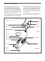
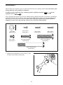
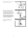
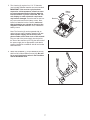
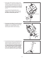
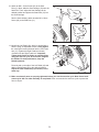
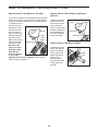
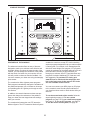
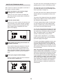
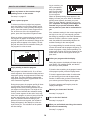
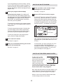
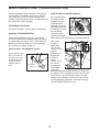
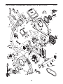
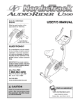
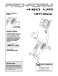
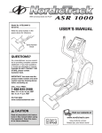
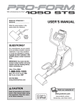
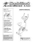
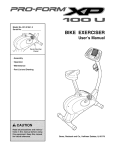
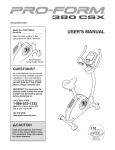
Model No. NTEX3196.0
Serial No.
USER'S MANUAL
Serial Number
Decal (under frame)
QUESTIONS?
As a manufacturer, we are committed to providing complete
customer satisfaction. If you
have questions, or if parts are
damaged or missing, PLEASE
CONTACT OUR CUSTOMER
SERVICE DEPARTMENT
DIRECTLY.
Visit our website at
www.proform.com
new products, prizes,
fitness tips, and much more!
CALL TOLL-FREE:
1-888-825-2588
Mon.–Fri., 6 a.m.–6 p.m. MST
Sat. 8 a.m.–4 p.m. MST
ON THE WEB:
www.nordictrackservice.com
CAUTION
Read all precautions and instructions in this manual before using
this equipment. Keep this manual
for future reference.
Visit our website at
www.healthrider.com
new products, prizes,
fitness tips, and much more!
Visit our website at
www.nordictrack.com
new products, prizes,
fitness tips, and much more!
TABLE OF CONTENTS
IMPORTANT PRECAUTIONS . . . . . . . . . . . . . . . . . . . . . . . . . . . . . . . . . . . . . . . . . . . . . . . . . . . . . . . . . . . . . . . .3
BEFORE YOU BEGIN . . . . . . . . . . . . . . . . . . . . . . . . . . . . . . . . . . . . . . . . . . . . . . . . . . . . . . . . . . . . . . . . . . . . . .4
ASSEMBLY . . . . . . . . . . . . . . . . . . . . . . . . . . . . . . . . . . . . . . . . . . . . . . . . . . . . . . . . . . . . . . . . . . . . . . . . . . . . . . .5
HOW TO OPERATE THE EXERCISE CYCLE . . . . . . . . . . . . . . . . . . . . . . . . . . . . . . . . . . . . . . . . . . . . . . . . . . .10
MAINTENANCE AND TROUBLESHOOTING . . . . . . . . . . . . . . . . . . . . . . . . . . . . . . . . . . . . . . . . . . . . . . . . . . .17
CONDITIONING GUIDELINES . . . . . . . . . . . . . . . . . . . . . . . . . . . . . . . . . . . . . . . . . . . . . . . . . . . . . . . . . . . . . . .18
PART LIST . . . . . . . . . . . . . . . . . . . . . . . . . . . . . . . . . . . . . . . . . . . . . . . . . . . . . . . . . . . . . . . . . . . . . . . . . . . . . .22
EXPLODED DRAWING . . . . . . . . . . . . . . . . . . . . . . . . . . . . . . . . . . . . . . . . . . . . . . . . . . . . . . . . . . . . . . . . . . . .23
ORDERING REPLACEMENT PARTS . . . . . . . . . . . . . . . . . . . . . . . . . . . . . . . . . . . . . . . . . . . . . . . . . .Back Cover
LIMITED WARRANTY . . . . . . . . . . . . . . . . . . . . . . . . . . . . . . . . . . . . . . . . . . . . . . . . . . . . . . . . . . . . . .Back Cover
NordicTrack is a registered trademark of ICON IP, Inc.
2
IMPORTANT PRECAUTIONS
WARNING:
To reduce the risk of serious injury, read the following important precautions before using the exercise cycle.
1. Read all instructions in this manual and all
warnings on the exercise cycle before using
the exercise cycle.
10. The pulse sensor is not a medical device.
Various factors, including the user's movement, may affect the accuracy of heart rate
readings. The pulse sensor is intended only
as an exercise aid in determining heart rate
trends in general.
2. Use the exercise cycle only as described in
this manual.
3. It is the responsibility of the owner to ensure
that all users of the exercise cycle are adequately informed of all precautions.
11. Always keep your back straight while using
the exercise cycle; do not arch your back.
12. If you feel pain or dizziness while exercising,
stop immediately and cool down.
4. The exercise cycle is intended for home use
only. Do not use the exercise cycle in
a commercial, rental, or institutional setting.
13. The decal shown below has been placed on
the exercise cycle. If the decal is missing or
illegible, call the toll-free telephone number
on the front cover of this manual and order a
free replacement decal. Apply the decal in
the location shown.
5. Keep the exercise cycle indoors, away from
moisture and dust. Place the exercise cycle
on a level surface, with a mat beneath it to
protect the floor or carpet. Make sure that
there is enough clearance around the exercise cycle to mount, dismount, and use it.
6. Inspect and properly tighten all parts regularly. Replace any worn parts immediately.
7. Keep children under the age of 12 and pets
away from the exercise cycle at all times.
8. Wear appropriate clothes while exercising;
do not wear loose clothes that could become
caught on the exercise cycle. Always wear
athletic shoes for foot protection.
9. The exercise cycle should not be used by
persons weighing more than 300 lbs.
(136 kg).
WARNING:
Before beginning this or any exercise program, consult your physician.
This is especially important for persons over the age of 35 or persons with pre-existing health problems. Read all instructions before using. ICON assumes no responsibility for personal injury or
property damage sustained by or through the use of this product.
3
BEFORE YOU BEGIN
after reading this manual, please see the front cover
of this manual. To help us assist you, note the product
model number and serial number before contacting
us. The model number is NTEX3196.0. The serial
number can be found on a decal attached to the exercise cycle (see the front cover of this manual for the
location of the decal).
Congratulations for selecting the revolutionary
NordicTrack® AUDIORIDER U300 exercise cycle.
Cycling is one of the most effective exercises for
increasing cardiovascular fitness, building endurance,
and toning the entire body. The AUDIORIDER U300
exercise cycle offers an impressive array of features
designed to let you enjoy this healthful exercise in the
comfort and convenience of your home.
Before reading further, please familiarize yourself with
the parts that are labeled in the drawing below.
For your benefit, read this manual carefully before
you use the exercise cycle. If you have questions
Handgrip Pulse Sensor
Fan
Handlebar
Console
Stereo Speakers
Padded Armrest
Water Bottle Holder
(no water bottle is included)
FRONT
Seat
Seat Knob
Pedal with Strap
Seat Post
Seat Post Knob
Wheel
Side Shield
REAR
RIGHT SIDE
Leveling Foot
4
ASSEMBLY
Place all parts of the exercise cycle in a cleared area and remove the packing materials. Do not dispose of the
packing materials until assembly is completed.
In addition to the included hex keys, assembly requires a phillips screwdriver
adjustable wrench
.
and an
As you assemble the exercise cycle, use the drawings below to identify small parts. The number in parentheses
below each drawing is the key number of the part, from the PART LIST on page 22. The number following the
parentheses is the quantity used in assembly. Note: Some small parts may have been preassembled for
shipping. If a part is not in the parts bag, check to see if it has been preassembled.
M10 Split
Washer (55)–3
M6 x 10mm
Screw (60)–2
M4 x 12mm
Screw (64)–1
M4 x 16mm
Screw (54)–6
M6 x 30mm Button
Screw (46)–4
M4 x 19mm
Screw (47)–2
M10 x 50mm Button
Screw (48)–3
M10 x 85mm Button
Screw (56)–4
1. Attach the Front Stabilizer (2) to the Frame (1) with
two M10 x 85mm Button Screws (56).
1
1
2
56
5
2. Attach the Rear Stabilizer (3) to the Frame (1) with
two M10 x 85mm Button Screws (56).
2
3
1
56
3. While another person holds the Handlebar Post (6)
near the Frame (1), connect the Upper Wire
Harness (51) to the Lower Wire Harness (50) and
the Power Jack Wire (65). Next, pull the excess
Upper Wire Harness out of the top of the Handlebar
Post, and slide the Handlebar Post onto the Frame.
Be careful not to pinch the Wire Harnesses.
3
6
55
55
48
48
51
55
Attach the Handlebar Post (6) to the Frame (1) with
three M10 x 50mm Button Screws (48) and three
M10 Split Washers (55); tighten the two Button
Screws in the front of the Handlebar Post first,
and then tighten the third Button Screw.
50
65
1
4. Attach the Water Bottle Holder (18) to the
Handlebar Post (6) with two M4 x 19mm
Screws (47).
4
18
6
47
6
5. The Console (9) requires four 1.5V “D” batteries
(not included); alkaline batteries are recommended.
IMPORTANT: If the exercise cycle has been
exposed to cold temperatures, allow it to warm
to room temperature before inserting batteries
into the Console. If you do not do this, the console displays or other electronic components
may become damaged. Press the tabs on the battery covers and remove the battery covers. Next,
insert four batteries into the Console; make sure
that the batteries are oriented as shown by the
diagrams inside the Console. Then, reattach the
battery covers.
5
Battery
Covers
Batteries
Batteries
9
Note: The Console (9) can be operated with an
optional power supply instead of batteries. To purchase a power supply, call the toll-free telephone number on the front cover of this manual.
Plug one end of the power supply into the jack at
the front of the exercise cycle. Plug the other end of
the power supply into an appropriate outlet that is
properly installed in accordance with all local codes
and ordinances.
6. Attach the Handlebar (7) to the Handlebar Post (6)
with four M6 x 30mm Button Screws (46). Be careful to avoid pinching the wires in the Handlebar
and the Handlebar Post.
6
46
7
6
7
7. While another person holds the Console (9) near
the Handlebar (7), connect the wire harness on the
Console to the Upper Wire Harness (51). Next, connect the pulse wire on the Console to the Pulse Grip
Wire (10). Note: The remaining wire on the Console
is used during the manufacturing process; disregard
this wire.
7
9
Pulse
Wire
Insert the excess wiring downward into the
Handlebar Post (6). Attach the Console (9) to the
Handlebar (7) with four M4 x 16mm Screws (54).
Be careful to avoid pinching the wires.
10
7
Wire Harness
51
54
6
8. Slide the Bottom Handlebar Cover (33) into the slots
in the bottom of the Console (9). Attach the Bottom
Handlebar Cover to the Handlebar (7) and the Top
Handlebar Cover (30) with two M4 x 16mm
Screws (54) and one M4 x 12mm Screw (64).
8
30
9
7
Slot
33
54
64
54
9. Turn the Seat Post Knob (20) counterclockwise several turns to loosen it. Next, pull the Seat Post Knob
outward, and insert the Seat Post (11) into the
Frame (1). Slide the Seat Post upward or downward
to the desired position, and release the Seat Post
Knob. Move the Seat Post up or down slightly to
make sure that the Seat Post Knob is engaged
in one of the adjustment holes in the Seat Post.
Then, turn the Seat Post Knob clockwise to tighten it.
9
11
1
20
8
10. Attach an M6 x 10mm Screw (60) to the Seat
Post (11). Next, slide the Seat Carriage (19) onto the
Seat Post. Then, adjust the Seat Carriage to the
desired position and tighten the Seat Knob (31) into
the Seat Carriage.
10
60
11
31
See the inset drawing. Attach another M6 x 10mm
Screw (60) to the Seat Post (11).
19
60
11
11. Identify the Left Pedal (40), which is marked with a
sticker. Using an adjustable wrench, firmly tighten
the Left Pedal counterclockwise into the Left Crank
Arm (15). Tighten the Right Pedal (not shown)
clockwise into the Right Crank Arm. Important:
Tighten both Pedals as firmly as possible. After
using the exercise cycle for one week, retighten
the Pedals. For best performance, keep the
Pedals tightened.
11
25
Press the tab on the side of the Left Pedal (40) and
adjust a Pedal Strap (25) to the desired position.
Adjust the other Pedal Strap (not shown) in the
same way.
Tab
40
15
12. Make sure that all parts are properly tightened before you use the exercise cycle. Note: Some hardware may be left over after assembly is completed. Place a mat under the exercise cycle to protect the
floor or carpet.
9
HOW TO OPERATE THE EXERCISE CYCLE
HOW TO ADJUST THE HEIGHT OF THE SEAT
HOW TO ADJUST THE LATERAL POSITION OF
THE SEAT
For effective exercise, the seat should be at the proper
height. As you pedal, there should be a slight bend in
your knees when the pedals are in the lowest position.
To adjust the seat,
first turn the seat
post knob counterclockwise several
Seat
turns to loosen it.
Next, pull the knob,
slide the seat post
Seat
upward or downPost
Knob
ward to the desired
position, and then
Seat Post
release the knob.
Move the seat
post up or down
slightly to make
sure that the
knob is engaged
in one of the
adjustment holes in the seat post. Then, turn the
knob clockwise to tighten it.
To adjust the lateral
position of the seat,
first loosen the seat
knob a few turns.
Then, move the seat
forward or backward
to the desired position, and firmly tighten the seat knob.
Seat
Seat Knob
Seat Post
HOW TO ADJUST THE PEDAL STRAPS
To adjust the pedal
straps, first pull the
ends of the straps
off the tabs on the
pedals. Adjust the
straps to the
desired position,
and press the ends
of the straps onto
the tabs.
10
Strap
Tab
CONSOLE DIAGRAM
FEATURES OF THE CONSOLE
The advanced console offers an array of features
designed to make your workouts more effective and
enjoyable. When you select the manual mode of the
console, you can change the resistance of the pedals
with the touch of a button. As you exercise, the console will provide continuous exercise feedback. You
can even measure your heart rate using the handgrip
pulse sensor.
The console also offers eighteen preset programs.
Each program automatically changes the resistance of
the pedals and prompts you to increase or decrease
your pedaling pace as it guides you through an effective workout.
In addition, the console features two heart rate programs that change the resistance of the pedals to
keep your heart rate near target heart rate settings
while you exercise.
The console also features the new iFIT Interactive
Workout System. The iFIT Interactive Workout System
enables the console to accept iFIT Cards containing
workout programs designed to help you achieve specific fitness goals. For example, lose unwanted pounds
with the 8-week Weight Loss program. iFIT programs
control the resistance of the pedals while the voice of a
personal trainer coaches you and motivates you
through your workouts. One iFIT Card with three new
programs is included. Additional iFIT Cards are available separately. To purchase iFIT Cards, go to
www.iFIT.com or call the toll-free telephone number on the front cover of this manual. iFIT Cards
are also available at select stores.
You can even connect your MP3 player or CD player
to the console’s stereo sound system and listen to
your favorite workout music or audio books while you
exercise.
To use the manual mode of the console, follow the
steps beginning on page 12. To use a preset
program, see page 14. To use a heart rate program,
see page 15. To use an iFIT program, see page 16.
To use the stereo sound system, see page 16.
11
The lower left corner of the display will show your
pedaling speed, in miles or kilometers per hour.
HOW TO USE THE MANUAL MODE
The upper right corner of the display will show
your heart rate when you use the handgrip pulse
sensor (see step 5 on page 13).
Note: If there is a sheet of clear plastic on the face of
the console, remove the plastic.
1
Press any button on the console or begin
pedaling to turn on the console.
The lower right corner of the display will show the
distance that you have pedaled, in miles or kilometers.
When you turn on the console, the display will
light. A tone will then sound and the console will
be ready for use.
2
The center of the display will show the resistance
setting of the pedals for a few seconds each time
the resistance setting changes.
Select the manual mode.
When you turn on the console, the manual mode
will be selected. If you have selected a program,
reselect the manual mode by pressing the Heart
Rate Programs button repeatedly until zeros
appear in the display.
To view the approximate number of calories that
you are burning per hour and the approximate
number of calories that you have burned during
your workout, press the Display button.
You can also view selected information at a larger
size. Press the Display button repeatedly to view
the elapsed time, the distance that you have pedaled, your pedaling speed, or the approximate
number of calories that you have burned.
To again view the elapsed time, your pedaling
speed, and the distance that you have pedaled,
press the Display button again.
3
To view the total distance pedaled since the exercise cycle was purchased and the trip distance,
press the Odometer button. The information will
appear in the display for a few seconds. To reset
the trip distance, hold down the Odometer button
for a few seconds.
Begin pedaling and change the resistance of
the pedals as desired.
As you pedal, change the resistance of the pedals by pressing the OneTouch Resistance buttons. There are sixteen resistance levels. Note:
After you press the buttons, it will take a moment
for the pedals to reach the selected resistance
level.
4
Note: The console can show speed and distance in either miles or kilometers. To determine
which unit of measurement is selected, hold down
the decrease button below the Odometer button
for a few seconds. The words UNITS: ENGLISH or
UNITS: METRIC will appear in the display. Press
the increase button to change the unit of measurement if desired. Then, press the decrease button
again. Note: When the batteries are replaced, it
may be necessary to reselect the desired unit of
measurement.
Follow your progress with the display.
While you pedal, the upper left corner of the display will show the elapsed time.
12
5
Measure your heart rate if desired.
6
If there are
sheets of clear
Contacts
plastic on the
metal contacts
on the handgrip
pulse sensor,
remove the plastic. In addition,
make sure that
your hands are
clean. To measure your heart
rate, hold the handgrip pulse sensor with your
palms resting against the metal contacts. Avoid
moving your hands or gripping the contacts
tightly.
Turn on the fan if desired.
To turn on the fan at high speed, press the Fan
button. To turn on the fan at low speed, press the
Fan button a second time. To select the auto
mode, press the Fan button again; when the auto
mode is selected, the speed of the fan will automatically increase or decrease as you increase or
decrease your pedaling speed.
Pivot the fan louvers above the display upward or
downward to direct the airflow from the fan.
To turn off the fan, press the Fan button again.
Note: If the pedals are not moved for about thirty
seconds, the fan will automatically turn off to conserve the batteries.
7
When your pulse is detected, your heart rate will
be shown in the display. For the most accurate
heart rate reading, hold the contacts for at least 15
seconds.
When you are finished exercising, the console
will turn off automatically.
If the pedals are not moved for several seconds, a
series of tones will sound and the console will
pause.
If your heart rate is not shown, make sure that
your hands are positioned as described. Be careful not to move your hands excessively or to
squeeze the metal contacts tightly. For optimal
performance, clean the metal contacts using a
soft cloth; never use alcohol, abrasives, or
chemicals to clean the contacts.
If the pedals are not moved for about five minutes, the console will turn off and the displays will
be reset.
13
As you exercise, you
will be prompted to
Arrow
keep your pedaling
pace near the target
pace setting for the
current segment.
When an upward-pointing arrow appears in the
display, increase your pace. When a downwardpointing arrow appears, decrease your pace.
When no arrow appears, maintain your current
pace. Important: The target pace settings are
intended only to provide motivation. Make
sure to pedal at a pace that is comfortable for
you.
HOW TO USE A PRESET PROGRAM
1
Press any button on the console or begin
pedaling to turn on the console.
See step 1 on page 12.
2
Select a preset program.
To select one of the six weight loss programs,
press the Weight Loss Programs button repeatedly; to select one of the six aerobic fitness programs, press the Aerobic Fitness Programs button; to select one of the six competition programs, press the Competition Programs button.
If the resistance setting for the current segment is
too high or too low, you can manually override
the setting by pressing the OneTouch Resistance
buttons. However, when the current segment
ends, the pedals will automatically adjust to the
resistance setting for the next segment.
When you select a preset program, the name of
the program will appear in the display for a few
seconds. A profile of the resistance settings of the
program will then appear in the display. The display will also show the first resistance setting for
the program for a few seconds.
If you stop pedaling for several seconds, a series
of tones will sound and the program will pause. To
restart the program, simply resume pedaling. The
program will continue until the last segment of the
profile flashes and the last segment of the program ends.
Profile
4
Follow your progress with the display.
During the program, the display will show the program profile, your pedaling speed, and the distance that you have pedaled.
3
Begin pedaling to start the program.
To view the time remaining in the program instead
of the program profile, press the Display button.
Each program is divided into 20, 30, or 45 oneminute segments. One resistance setting and one
target pace setting are programmed for each segment. Note: The same resistance setting and/or
target pace setting may be programmed for two or
more consecutive segments.
To view the approximate number of calories that
you are burning per hour and the approximate
number of calories that you have burned during
your workout, press the Display button again.
To view the program profile again, press the
Display button again.
During the program, the program profile will show
your progress (see the drawing above). The
flashing column of the profile represents the current segment of the program. The height of the
flashing column indicates the resistance setting
for the current segment. At the end of each segment of the program, a series of tones will sound
and the next segment of the profile will begin to
flash. If a different resistance setting is programmed for the next segment, the resistance
setting will appear in the display for a few seconds to alert you. The resistance of the pedals
will then change.
5
Measure your heart rate if desired.
See step 5 on page 13.
6
Turn on the fan if desired.
See step 6 on page 13.
7
When you are finished exercising, the console
will turn off automatically.
See step 7 on page 13.
14
Heart rate program 2 is divided into 30 oneminute segments. One target heart rate setting is
programmed for each segment. Note: The same
target heart rate setting may be programmed for
consecutive segments.
HOW TO USE A HEART RATE PROGRAM
1
Press any button on the console or begin
pedaling to turn on the console.
During the program, the program profile in the
display will show your progress. The flashing column of the profile represents the current segment
of the program. The height of the flashing column
indicates the target heart rate setting for the current segment. At the end of each segment of the
program, a series of tones will sound and the
next segment of the profile will begin to flash.
See step 1 on page 12.
2
Select a heart rate program.
To select one of the heart rate programs, press
the Heart Rate Programs button repeatedly until
the words HEART RATE 1 or HEART RATE 2
appear in the display.
3
Enter a target heart rate setting.
Profile
A few seconds after you select a heart rate program, the words ENTER HEART RATE will
appear in the display and the number 110 will
begin to flash.
Arrow
During heart rate program 1, the same target
heart rate setting will be programmed for all segments of the program. If you have selected heart
rate program 1, press the increase and decrease
buttons below the Odometer button to enter the
desired target heart rate setting (see EXERCISE
INTENSITY on page 18).
During both programs, the console will regularly
compare your heart rate to the target heart rate
setting for the current segment of the program. If
your heart rate is too far below or above the target heart rate setting, the resistance of the pedals
will automatically increase or decrease to bring
your heart rate closer to the target heart rate setting. Each time the resistance changes, the resistance setting will appear in the display for a few
seconds to alert you.
During heart rate program 2, different target
heart rate settings will be programmed for different segments of the program. If you have selected heart rate program 2, press the increase and
decrease buttons below the Odometer button to
enter the desired maximum target heart rate setting for the program (see EXERCISE INTENSITY
on page 18).
4
While you exercise, you will be prompted to
maintain a constant pedaling pace. If an upwardpointing arrow appears in the display (see the
drawing above), increase your pace. If a downward-pointing arrow appears, decrease your
pace. When no arrow appears, maintain your current pace.
Hold the handgrip pulse sensor.
It is not necessary to hold the handgrip pulse
sensor continuously during heart rate programs;
however, you should hold the handgrip pulse sensor frequently for the programs to operate properly. Each time you hold the handgrip pulse sensor, keep your hands on the metal contacts
for at least 30 seconds.
5
If the resistance setting for the current segment is
too high or too low, you can manually override
the setting by pressing the OneTouch Resistance
buttons. However, when the console compares
your heart rate to the target heart rate setting, the
resistance of the pedals may automatically
increase or decrease to bring your heart rate
closer to the target heart rate setting.
Begin pedaling to start the program.
Heart rate program 1 is divided into 40 oneminute segments. Note: For a shorter workout,
stop exercising or select a different program
before the program ends.
15
If you stop pedaling for several seconds, a series
of tones will sound and the program will pause. To
restart the program, simply resume pedaling. The
program will continue until the last segment of the
program ends.
6
HOW TO USE AN IFIT PROGRAM
1
Press any button on the console or begin
pedaling to turn on the console.
See step 1 on page 12.
Follow your progress with the display.
During heart rate program 1, the display will
show your heart rate, your pedaling speed, and
the distance that you have pedaled. During heart
rate program 2, the display will show the program profile, your pedaling speed, and the distance that you have pedaled.
2
Insert an iFIT Card and select a program.
To use an iFIT program, insert an iFIT Card into
the iFIT slot; make sure that the iFIT Card is oriented so the metal contacts are face-down and
are facing the slot. When the iFIT Card is properly inserted, the indicator next to the slot will light
and the words IFIT 1 will appear in the display.
To view the time remaining in the program instead
of your heart rate or the program profile, press the
Display button.
To view the approximate number of calories that
you are burning per hour and the approximate
number of calories that you have burned during
your workout, press the Display button again.
iFIT Slot
iFIT Card
To view your heart rate or the program profile
again, press the Display button again.
7
Next, select the desired program on the iFIT Card
by pressing the up and down buttons next to the
iFIT slot.
Turn on the fan if desired.
See step 6 on page 13.
8
A moment after you select a program, the voice
of a personal trainer will begin guiding you
through your workout. iFIT programs work in the
same way as preset programs. To use the program, see steps 3 to 6 on page 14.
When you are finished exercising, the console
will turn off automatically.
See step 7 on page 13.
HOW TO USE THE STEREO SOUND SYSTEM
To play music or audio
books through the console’s stereo sound system
Cable
while you exercise, first
locate the stereo audio
cable in the center of the
console above the speakers. Plug the cable into a
jack on your MP3 player or CD player; make sure
that the audio cable is fully plugged in.
Next, press the play button on your MP3 player or CD
player. Adjust the volume of the speakers using the
volume control on your MP3 player or CD player.
When it is not in use, insert the stereo audio cable
into the storage recess on the console.
16
MAINTENANCE AND TROUBLESHOOTING
Inspect and properly tighten all parts of the exercise
cycle regularly. The exercise cycle can be cleaned
with a soft, damp cloth. To prevent damage to the
console, keep liquids away from the console and keep
the console out of direct sunlight.
HOW TO ADJUST THE REED SWITCH
If the console does
4
not display correct
feedback, the reed
switch should be
8
adjusted. First, use a
small flat screwdriver
to carefully pry off the
14
left Side Shield
Cover (14). Next,
rotate the left Pedal
Guard (8) and pull it away from the Left Side Shield (4).
TIGHTENING THE PEDALS
For best performance, regularly tighten both pedals.
CONSOLE TROUBLESHOOTING
If the console display becomes dim, the batteries
should be replaced. See assembly step 5 on page 6
for replacement instructions. If the console does not
display your heart rate when you use the handgrip
pulse sensor, see step 5 on page 13.
Next, locate
the Reed
Switch (49).
Turn the Left
15
Crank Arm (15)
until the
Magnet (23) is
aligned with
49
the Reed
23
Switch.
54
Loosen, but do
not remove,
the indicated
M4 x 16mm
Screw (54).
Slide the Reed Switch slightly closer to or away from
the Magnet. Then, retighten the Screw. Turn the Left
Crank Arm for a moment. Repeat until the console
displays correct feedback. When the Reed Switch is
correctly adjusted, reattach the left Pedal Guard (8)
and the left Side Shield Cover (14).
HOW TO LEVEL THE EXERCISE CYCLE
If the exercise cycle
does not sit flat on
your floor, turn one
or both of the leveling feet until the
exercise cycle is
level.
Leveling
Feet
17
CONDITIONING GUIDELINES
Fat Burning
WARNING:
To burn fat effectively, you must exercise at a relatively low intensity level for a sustained period of time.
During the first few minutes of exercise, your body
uses easily accessible carbohydrate calories for energy. Only after the first few minutes of exercise does
your body begin to use stored fat calories for energy. If
your goal is to burn fat, adjust the intensity of your
exercise until your heart rate is near the lowest number or the middle number in your training zone as you
exercise.
Before beginning this or any exercise program, consult your physician. This is especially important for individuals over the age
of 35 or individuals with pre-existing health
problems.
The pulse sensor is not a medical device.
Various factors may affect the accuracy of
heart rate readings. The pulse sensor is
intended only as an exercise aid in determining heart rate trends in general.
Aerobic Exercise
If your goal is to strengthen your cardiovascular system, your exercise must be “aerobic.” Aerobic exercise
is activity that requires large amounts of oxygen for
prolonged periods of time. This increases the demand
on the heart to pump blood to the muscles, and on the
lungs to oxygenate the blood. For aerobic exercise,
adjust the intensity of your exercise until your heart
rate is near the highest number in your training zone.
The following guidelines will help you to plan your
exercise program. Remember that proper nutrition and
adequate rest are essential for successful results.
EXERCISE INTENSITY
Whether your goal is to burn fat or to strengthen your
cardiovascular system, the key to achieving the
desired results is to exercise with the proper intensity.
The proper intensity level can be found by using your
heart rate as a guide. The chart below shows recommended heart rates for fat burning, maximum fat burning, and cardiovascular (aerobic) exercise.
WORKOUT GUIDELINES
Each workout should include the following three parts:
A warm-up, consisting of 5 to 10 minutes of stretching
and light exercise. A proper warm-up increases your
body temperature, heart rate, and circulation in preparation for exercise.
Training zone exercise, consisting of 20 to 30 minutes of exercising with your heart rate in your training
zone. (During the first few weeks of your exercise program, do not keep your heart rate in your training
zone for longer than 20 minutes.)
A cool-down, with 5 to 10 minutes of stretching. This
will increase the flexibility of your muscles and will
help to prevent post-exercise problems.
To find the proper heart rate for you, first find your age
at the bottom of the chart (ages are rounded off to the
nearest ten years). Next, find the three numbers above
your age; the three numbers are your “training zone.”
The lowest number is the recommended heart rate for
fat burning; the middle number is the recommended
heart rate for maximum fat burning; and the highest
number is the heart rate for aerobic exercise.
EXERCISE FREQUENCY
To maintain or improve your condition, plan three workouts each week, with at least one day of rest between
workouts. After a few months of regular exercise, you
may complete up to five workouts each week, if
desired. The key to success is make exercise a regular and enjoyable part of your everyday life.
18
SUGGESTED STRETCHES
The correct form for several basic stretches is shown at the right.
Move slowly as you stretch—never bounce.
1
1. Toe Touch Stretch
Stand with your knees bent slightly and slowly bend forward from
your hips. Allow your back and shoulders to relax as you reach
down toward your toes as far as possible. Hold for 15 counts,
then relax. Repeat 3 times. Stretches: Hamstrings, back of knees
and back.
2
2. Hamstring Stretch
Sit with one leg extended. Bring the sole of the opposite foot
toward you and rest it against the inner thigh of your extended
leg. Reach toward your toes as far as possible. Hold for 15
counts, then relax. Repeat 3 times for each leg. Stretches:
Hamstrings, lower back and groin.
3. Calf/Achilles Stretch
3
With one leg in front of the other, reach forward and place your
hands against a wall. Keep your back leg straight and your back
foot flat on the floor. Bend your front leg, lean forward and move
your hips toward the wall. Hold for 15 counts, then relax. Repeat
3 times for each leg. To cause further stretching of the achilles
tendons, bend your back leg as well. Stretches: Calves, achilles
tendons and ankles.
4
4. Quadriceps Stretch
With one hand against a wall for balance, reach back and grasp
one foot with your other hand. Bring your heel as close to your
buttocks as possible. Hold for 15 counts, then relax. Repeat 3
times for each leg. Stretches: Quadriceps and hip muscles.
5. Inner Thigh Stretch
5
Sit with the soles of your feet together and your knees outward.
Pull your feet toward your groin area as far as possible. Hold for
15 counts, then relax. Repeat 3 times. Stretches: Quadriceps and
hip muscles.
19
NOTES
20
NOTES
21
PART LIST—Model No. NTEX3196.0
Key No. Qty.
1
2
3
4
5
6
7
8
9
10
11
12
13
14
15
16
17
18
19
20
21
22
23
24
25
26
27
28
29
30
31
32
33
34
1
1
1
1
1
1
1
2
1
2
1
1
1
2
1
1
2
1
1
1
2
1
1
1
2
2
1
1
2
1
1
1
1
1
Description
R0408A
Key No. Qty.
Frame
Front Stabilizer
Rear Stabilizer
Left Side Shield
Right Side Shield
Handlebar Post
Handlebar
Pedal Guard
Console
Pulse Grip/Wire
Seat Post
Seat
Collar
Side Shield Cover
Left Crank Arm
Right Crank Arm
Wheel
Water Bottle Holder
Seat Carriage
Seat Post Knob
Crank Bearing
Left Armrest
Magnet
Right Armrest
Pedal Strap
Crank Cover
Crank
Belt
Leveling Foot
Top Handlebar Cover
Seat Knob
Crank Snap Ring
Bottom Handlebar Cover
Pulley
35
36
37
38
39
40
41
42
43
44
45
46
47
48
49
50
51
52
53
54
55
56
57
58
59
60
61
62
63
64
65
*
*
2
1
1
1
1
1
1
2
2
1
2
4
2
3
1
1
1
4
4
29
3
4
4
4
1
2
4
4
4
1
1
1
2
Description
Wheel Cover
“J” Bracket
Right Pedal
Crank Washer
Flywheel
Left Pedal
Resistance Motor
Stabilizer Endcap
M8 Nylon Jamnut
Clamp
5/16" x 1" Flange Screw
M6 x 30mm Button Screw
M4 x 19mm Screw
M10 x 50mm Button Screw
Reed Switch/Wire
Lower Wire Harness
Upper Wire Harness
M6 x 16mm Screw
M6 Nylon Locknut
M4 x 16mm Screw
M10 Split Washer
M10 x 85mm Button Screw
M8 Nylon Locknut
M8 Split Washer
M4 x 5mm Screw
M6 x 10mm Screw
M6 Split Washer
M6 Washer
M6 Nylon Locknut
M4 x 12mm Screw
Power Jack/Wire
User’s Manual
Hex Key
Note: “*” indicates a non-illustrated part. Specifications are subject to change without notice. See the back cover
of this manual for information about ordering replacement parts.
22
EXPLODED DRAWING—Model No. NTEX3196.0
R0408A
37
9
10
25
24
54
16
22
26
5
54
46
45
54
14
54
54
54
7
8
30
54
54
54
54
54
60
54
33
18
64
54
47
19
20
13
58
6
58
35
51
55
55 48
48
57
49
17 43
55
2
21
23
61
17
32
56
34
38 52
63
1
65
43
27
52
54
44
59
36
54
53
12 11
31
61
62
21
42
62
41
35 54
39
29
3
54
54
25
56
29
45
42
54
28
4
26
50
8
15
14
54
40
23
ORDERING REPLACEMENT PARTS
To order replacement parts, please see the front cover of this manual. To help us assist you, be prepared to
provide the following information when contacting us:
• the MODEL NUMBER of the product (NTEX3196.0)
• the NAME of the product (NordicTrack AUDIORIDER U300 exercise cycle)
• the SERIAL NUMBER of the product (see the front cover of this manual)
• the KEY NUMBER and DESCRIPTION of the part(s) (see pages 22 to 23)
LIMITED WARRANTY
ICON Health & Fitness, Inc. (ICON) warrants this product to be free from defects in workmanship and
material, under normal use and service conditions, for a period of one (1) year from the date of purchase.
There is a lifetime warranty on the frame. This warranty extends only to the original purchaser. ICON's
obligation under this warranty is limited to replacing or repairing, at ICON's option, the product through
one of its authorized service centers. All repairs for which warranty claims are made must be pre-authorized by ICON. If the product is shipped to a service center, freight charges to and from the service center will be the customer’s responsibility. For in-home service, the customer will be responsible for a minimal trip charge. This warranty does not extend to any product or damage to a product caused by or attributable to freight damage, abuse, misuse, improper or abnormal usage or repairs not provided by an ICON
authorized service center; products used for commercial or rental purposes; or products used as store
display models. No other warranty beyond that specifically set forth above is authorized by ICON.
ICON is not responsible or liable for indirect, special or consequential damages arising out of or in connection with the use or performance of the product or damages with respect to any economic loss, loss
of property, loss of revenues or profits, loss of enjoyment or use, costs of removal or installation or other
consequential damages of whatsoever nature. Some states do not allow the exclusion or limitation of incidental or consequential damages. Accordingly, the above limitation may not apply to you.
The warranty extended hereunder is in lieu of any and all other warranties and any implied warranties of
merchantability or fitness for a particular purpose is limited in its scope and duration to the terms set forth
herein. Some states do not allow limitations on how long an implied warranty lasts. Accordingly, the above
limitation may not apply to you.
This warranty gives you specific legal rights. You may also have other rights which vary from state to state.
ICON HEALTH & FITNESS, INC., 1500 S. 1000 W., LOGAN, UT 84321-9813
Part No. 243950 R0408A
Printed in China © 2008 ICON IP, Inc.