1
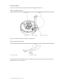
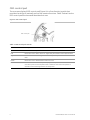
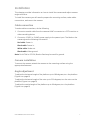
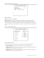
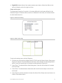
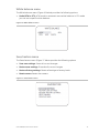
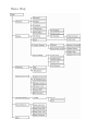
GE
Security
UVD-XP3DNR(-P) Camera User
Manual
REV 01.00 • ISS 02SEP09
Copyright
© 2009 GE Security, Inc.
This document may not be copied in whole or in part or otherwise reproduced without prior
written consent from GE Security, Inc., except where specifically permitted under US and
international copyright law.
Disclaimer
The information in this document is subject to change without notice. GE Security, Inc.
(“GE Security”) assumes no responsibility for inaccuracies or omissions and specifically disclaims
any liabilities, losses, or risks, personal or otherwise, incurred as a consequence, directly or
indirectly, of the use or application of any of the contents of this document. For the latest
documentation, contact your local supplier or visit us online at www.gesecurity.com.
This publication may contain examples of screen captures and reports used in daily operations.
Examples may include fictitious names of individuals and companies. Any similarity to names
and addresses of actual businesses or persons is entirely coincidental.
Trademarks and patents
GE and the GE monogram are trademarks of General Electric Company. The UltraView name
and logo are trademarks of GE Security.
Other trade names used in this document may be trademarks or registered trademarks of the
manufacturers or vendors of the respective products.
Intended use
Use this product only for the purpose it was designed for; refer to the data sheet and user
documentation for details. For the latest product information, contact your local supplier or visit
us online at www.gesecurity.com.
FCC compliance
This equipment has been tested and found to comply with the limits for a Class A digital device,
pursuant to part 15 of the FCC Rules. These limits are designed to provide reasonable protection
against harmful interference when the equipment is operated in a commercial environment.
This equipment generates, uses, and can radiate radio frequency energy and, if not installed
and used in accordance with the instruction manual, may cause harmful interference to radio
communications.
You are cautioned that any changes or modifications not expressly approved by the party
responsible for compliance could void the user ’s authority to operate the equipment.
Certification and compliance
European Union directives
1999/5/EC (R&TTE directive): Hereby, GE Security declares that this device is in compliance with
the essential requirements and other relevant provisions of Directive 1999/5/EC.
2002/96/EC (WEEE directive): Products marked with this symbol cannot be disposed of as
unsorted municipal waste in the European Union. For proper recycling, return this product to
your local supplier upon the purchase of equivalent new equipment, or dispose of it at
designated collection points. For more information see: www.recyclethis.info.
2004/108/EC (EMC directive): Non-European manufacturers must designate an authorized
representative in the Community. Our authorized manufacturing representative is:
GE Security B.V., Kelvinstraat 7,
6003 DH Weert, The Netherlands.
Contact information
For contact information see our Web site: www.gesecurity.com
EMEA: For contact information see our Web site: www.gesecurity.eu
Content
Preface 3
Safety terms 3
Product description 4
Features 4
User guidelines 4
Components 5
OSD control pad 6
Installation 7
Cable connection 7
Camera installation 7
Angle adjustment 7
Focus adjustment 8
Connect the monitor 8
Programming 9
Navigation 9
Main menu 9
Presets menu 10
Setup menu 10
Viewing menu 14
Exposure menu 14
White balance menu 15
Save/restore menu 15
Menu Map 16
UVD-XP3DNR(-P) Camera User Manual
i
Preface
This is the UVD-XP3DNR(-P) Camera. This document includes an overview of the
product and detailed instructions explaining:
•
how to connect the camera; and
•
how to program the camera.
•
how to adjust the camera angle and focus
To use this document effectively, you should have the following minimum
qualifications:
•
a basic knowledge of CCTV systems and components; and
•
a basic knowledge of electrical wiring and low-voltage electrical connections.
Note: A qualified service person, complying with all applicable codes, should perform
all required hardware installation.
Safety terms
These terms may appear in this manual:
CAUTION: Cautions identify conditions or practices that may result in damage to the
equipment or other property.
WARNING: Warnings identify conditions or practices that could result in equipment
damage or serious personal injury.
UVD-XP3DNR(-P) Camera User Manual
3
Product description
The UVD-XP3DNR(-P) (rugged dome) color video cameras is a 24 VAC/12 VDC model.
The cameras are equipped with a digital signal processor (DSP) for processing the
video signal.
Features
Camera features include:
•
Next-generation XPosure technology.
•
Improved low-light performance and color balance.
•
540 TVL lines color.
•
Dynamic range 95 dB (typical), 120 dB (maximum).
•
Preset modes optimized for various environments.
•
Onscreen display interface.
User guidelines
Use the following guidelines:
•
Program as many camera settings as possible before mounting the camera. Take
appropriate safety precautions while completing programming after installation.
•
Always use a 12 VDC or 24 VAC UL listed Class 2 power supply to power the
camera.
Do not use the camera outside the temperature range specifications: -57 to 122°F
(-50 to +50°C).
•
If the light source where the camera is installed experiences rapid, widevariations in lighting, the camera may not operate as intended.
WARNING: To reduce the risk of fire or electronic shock, do not expose the camera to
rain or moisture and do not remove the cover or back.
4
UVD-XP3DNR(-P) Camera User Manual
Components
Figure 1 shows the main components of the rugged dome unit.
Figure 1: Rugged dom2e unit
Lens body
Camera body
Bubble
OSD control pad
Video monitor output
Figure 3 shows the monitor output components.
Figure 2: Monitor output cable
A. Monitor output BNC
B. Monitor output RCA
Plug the monitor output RCA into the video monitor output and connect the monitor
output BNC to the TV monitor.
UVD-XP3DNR(-P) Camera User Manual
5
OSD control pad
The onscreen display (OSD) control pad (Figure 4) is a five-direction joystick that
provides the ability to manually control the camera functions. Table 1 below lists the
OSD control pad functions and describes their use.
Figure 3: OSD control pad
OSD control pad
Table 1: OSD control pad controls
6
Pad directions
Description
Up
Moves the cursor upward to select an item
Left
Moves the cursor left to select or adjust the parameters of the selected item.
Right
Moves the cursor to the right to select or adjust the parameters of the selected
item.
Down
Moves the cursor downward to select an item.
Enter
Press the center of the control pad to display the Setup menu. If the selected item has its
own menu, press the control pad to enter a submenu. Press the control pad for 2
seconds to save all settings and exit the Setup menu.
UVD-XP3DNR(-P) Camera User Manual
Installation
This chapter provides information on how to install the camera and adjust camera
angle and focus.
To install the camera you will need to prepare the mounting surface, make cable
connections, and mount the camera.
Cable connection
To make cable connections, do the following:
1. Connect a coaxial cable from the camera’s BNC connector to a CCTV monitor or
video recording device.
2. Connect a 12 VDC or 24 VAC power supply to the power input. The label on the
camera gives the following information:
Red cable. Power in.
Black cable. Power in.
White cable. Video out.
Black cable. Video ground.
Note: For AC24V or DC12V, Black or Red may be used for ground.
Camera installation
To mount the camera, attach the camera to the mounting surface using the
appropriate fasteners.
Angle adjustment
To adjust the horizontal angle of the platform up to 180 degrees, turn the platform
(Figure 4 on page 8).
To adjust the horizontal angle of the rotor up to 350 degrees, turn the rotor on the
platform (Figure 4 on page 8).
To adjust the vertical angle of the platform up to 90 degrees, turn the platform
(Figure 4 on page 8).
UVD-XP3DNR(-P) Camera User Manual
7
Figure 4: Camera adjustment
Platform horizontal adjustment
Platform vertical adjustment
Rotor horizontal adjustment
Focus adjustment
To adjust the camera zoom and focus, see Figure 6 and do the following:
1. Loosen the zoom ring thumbscrew.
2. Turn the zoom ring to set the desired zoom.
3. Tighten the zoom ring thumbscrew.
4. Loosen the focus ring thumbscrew.
5. Turn the focus ring to set the desired focus.
6. Tighten the focus ring thumbscrew.
Figure 5: Zoom and focus adjustment
Zoom ring thumbscrew for VA2 and focus ring for VA9 lens
Focus ring thumbscrew for VA2 and zooming ring for
VA9 lens
Connect the monitor
Program the cameras by attaching a standard video monitor to the system.
To connect the monitor, do the following:
1. Plug the monitor output cable (Figure 2 on page 5) to the video monitor output
connector (Figure 1 on page 5).
2. Connect the BNC cable to the video monitor.
3. Press Enter (see OSD control pad on page 9) to display the Setup menu.
8
UVD-XP3DNR(-P) Camera User Manual
Programming
This chapter describes how to navigate the programming menus to adjust the
camera settings.
Navigation
To access and navigate the menus, press and hold the center of the OSD control pad
(Figure 4 on page 7). Press Up or Down on the control pad to move between items,
and press Enter (center of the control pad) to select the item. Press Right or Left on
the control pad to select the different options available for the item.
You can return to the previous menu from any of the menus (except the Main menu)
by selecting the Previous page option.
Main menu
The Main menu (Figure 7) provides the following options:
•
“Presets menu” en page 10.
•
“Setup menu” en page 10.
•
“Viewing menu” en page 14.
•
“Exposure menu” en page 14.
•
“White balance menu” en page 15.
•
“Save/restore menu” en page 15.
•
Exit menu (exits the menu system).
There is a menu map provided on the back page of the manual.
Figure 6: Main menu
UVD-XP3DNR(-P) Camera User Manual
9
Presets menu
The Presets menu options include:
Normal. This is the camera default preset for general lighting conditions out of the
box. This mode supports 14 bits of dynamic range and gives priority to rendering the
highlights in the scene.
Indoor. This preset supports 16 bits of dynamic range and gives priority to rendering
the shadows in the scene.
Outdoor. This preset offers the highest dynamic range of 17 bits and gives priority to
rendering the highlights in the scene.
Flickerless. This mode uses line lock to eliminate phase roll under fluorescent lights. It
must be used with a 24 VAC power supply.
NTSC50Hz. This mode uses a DC iris lens to reduce phase roll under fluorescent lights.
This mode will not function correctly with a manual iris lens.
Setup menu
The Setup menu (Figure 8) provides the following options:
•
“Camera ID setup menu” più sotto.
•
“Sync menu” en page 11.
•
“Motion detection setup” en page 11.
•
WDR setup (safe area, center spot, lower 1/3, or full screen).
Figure 7: Setup menu
Camera ID setup menu
The Camera ID setup menu (Figure 9) provides the following options:
•
ID display (off or on).
•
Camera ID. Press Right to move the cursor to edit the camera ID. Press Up or
Down to select the ID. When complete, press Up or Down to leave the editing field.
•
ID position (up-left, up-center, up-right, down-left, or down-left).
10
UVD-XP3DNR(-P) Camera User Manual
Figure 8: Camera ID setup
Sync menu
The SYNC option in Setup menu (Figure 8 on page 19) provides the following INT or LL
(LINE LOCK) options:
INT. Internal sync. Used with DC power input to reduce the phase roll of fluorescent
lights.
LL. Line lock. Used to sync video for AC power input so that the sync matches the
frequency of the power input to eliminate the roll caused by fluorescent lights. (Figure
10)
Figure 9: LineLock menu
Motion detection setup
The Motion detection setup display (Figure 10 on page 12) provides the following
options:
•
“Motion options” en page 12.
•
“Setup motion zone” en page 13
UVD-XP3DNR(-P) Camera User Manual
11
Figure 10: Motion detection zone setup
Motion options
Off. Motion detection is disabled.
Motion det. Motion detection is enabled, with default motion settings. Enter the
submenu (Figure 11 below) to change the settings (see “Motion detection menu”
below). When motion is detected, the word “Alarm” is displayed on the top left of the
screen, and the image is zoomed, tilted, and panned to the area setup in Setup alarm
zone.
Figure 11: Motion detection menu
Motion detection menu
The Motion detection menu (Figure 11 above) provides the following options:
•
Motion Threshold. Set the level of sensitivity of the motion detection.
•
Digital zoom. Determine how far in the camera zooms upon alarm. By default, the
camera zooms to the center of the screen.
•
Digital pan. Adjust where the camera zooms upon alarm. Move the slider to the
left to pan left, and to the right to pan right.
12
UVD-XP3DNR(-P) Camera User Manual
•
Digital tilt. Adjust where the camera zooms upon alarm. Move the slider to the
left to tilt down, and to the right to tilt up.
Setup motion zone
The camera will monitor for motion in the area defined in the boxes defined in this
submenu (Figure 12 below). When motion is detected in this area, the camera issues
an alarm and zooms in.
Figure 12: Motion zone setup
Figure 13: Alarm zone setup
To set up the alarm zone, do the following:
1. Choose one of the options Adjust Zone 1/2/3/4 from the Setup Motion Zone menu
(Figure 12 above). The selected zone will have a thick border and be highlighted in
white. Press the arrow keys to change the selected zone (Figure 14).
2. Press Enter. The selected zone becomes green. Press the arrow keys to increase
the zone area.
3. Press Enter. The selected zone becomes red. Press the arrow keys to shrink the
zone area.
4. Press Enter for a few moments to leave the Alarm Zone Setup menu and return to
Motion Zone Setup menu.
UVD-XP3DNR(-P) Camera User Manual
13
Viewing menu
The Viewing menu (Figure 14 below) provides the following options:
•
Flip. (OFF, HORIZ, VERT, BOTH)
Turn horizontal flip off or on.
•
Resolution. (HIGH, NORMAL) High or normal. The High option over-sharpens the
image for higher resolution.
Figure 14: Viewing menu
Exposure menu
The Exposure menu (Figure 15 below) provides the following options:
•
AGC (medium, high, custom, or low). The camera automatically adjusts the image
quality in low light conditions.
•
AE preferences (highlights or shadows).
•
Range control (low, normal, high, or custom).
•
Shutter limit (x2, x4, x8, x16, x32, or off). A fast shutter speed captures clear
images of fast action.
•
Frame RPT (OFF/ON).
•
B/W Control (OFF/ON).
Figure 15: Exposure menu
14
UVD-XP3DNR(-P) Camera User Manual
White balance menu
The White balance menu (Figure 16 below) provides the following options:
•
Mode (ATW or PTL). ATW mode is automatic trace white balance. In PTL mode
you can set a specific white balance.
Figure 16: White balance menu
Save/restore menu
The Save/restore menu (Figure 17 below provides the following options:
•
Save user settings. Saves all current changes.
•
Restore user settings. Discards all current changes.
•
Restore factory settings. Resets all settings to factory levels.
•
Reset camera. Resets the camera.
Figure 17: Save/restore menu
UVD-XP3DNR(-P) Camera User Manual
15
Menu Map