1
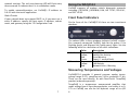
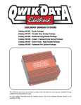
Contents
INTRODUCTION .................................................................................. 2
Who uses the J2534 API?
How to use a PassThru device
GETTING STARTED WITH CARDAQ2534 ................................ 4
Hardware Setup
Software setup
USING CARDAQ2534 ........................................................................ 8
Front Panel Indicators
Measuring Temperatures and Voltages
EXISTING SOFTWARE......................................................................10
OEM Diagnostic Software
OEM Reflashing Software
DrewTech Examples
Sourceforge SAE J1699 Implementation
DEVELOPING CUSTOM APPLICATIONS ..................................12
Using C, C++ under Windows
Using Linux, and Other Environments
Using LabVIEW
TROUBLESHOOTING AND SUPPORT .......................................13
SPECIFICATIONS AND CONNECTORS .....................................15
Isolated RS-232 Connector
Analog Connector
Vehicle Connector
Ethernet Connector
NOTICES ABOUT TESTING AND CERTIFICATION..............18
Statements
United States
European Union
Introduction
In 1994, the EPA mandated that all light-duty vehicles have a
standard connector for On-Board Diagnostics (OBD). The SAE
(Society of Automotive Engineers) created the OBD standard,
also known as 'J1962'. This standard specifies the size,
position and design of the OBD connector. Anyone can plug
a device (called a scan tool) into the connector to monitor
the car's emissions and review any recent emission-related
faults.
A computer in the car called the Engine Control Unit (ECU)
controls the fuel injection, spark plugs and (indirectly) the
car's emissions. The software running on the ECU is called
'firmware' because it's more difficult to change than normal
software. One ECU can be used in many different car models
with only slight changes to the ECU firmware. In fact, one car
model can comply with emission laws in different countries
just by modifying the firmware. Upgraded firmware can fix
bugs and tighten emissions output long after a car leaves the
factory.
The EPA quickly realized that a car's emissions are only as
good as the firmware on the ECU. Until now, only auto
dealers were able to upgrade the ECU firmware with tools
that sometimes cost as much as the car itself. Starting with
model year 2004, the EPA wants anyone (including auto
repair shops and car enthusiasts) to be able to upgrade their
car "for a reasonable cost." To accomplish this, they asked
SAE to create the J2534 API.
Who uses the J2534 API?
The EPA requires car manufacturers to release software that
updates the firmware on their cars. The application must run
on Windows and use the J2534 API to talk to the car. Anyone
can buy this software, even individual car enthusiasts. The
software must be sold “for a reasonable price”.
2
The combination of “reasonable price” ECU upgrade software
and competition among J2534 device manufacturers will
create new markets. We predict that car repair shops and
some car enthusiasts will find it profitable to charge for ECU
upgrades. Imagine pulling into Midas or Jiffy Lube and
learning, "Your car manufacturer recommends new ECU
firmware. It will cost a few dollars, but it will help your
engine run cleaner." By purchasing the upgrade, consumers
will be helping to cleanup the environment.
How to use a PassThru device
A PassThru device plugs into a car's OBD connector on one
side, and a computer on the other side. These devices are
not made by car manufacturers, but by any company that
sees an opportunity. Under the hood, the device must speak
a myriad of different vehicle protocols (ISO9141,
J1850VPW/PWM, CAN, etc.) used by the different
manufacturers. Each protocol has different voltage and
timing requirements, so this is no trivial task. Fortunately,
each device comes with a software driver that implements
the J2534 API. Since the driver invisibly handles
communication to the device, application software writers
don't have to worry about the connection details or low-level
car protocols.
Getting Started with CarDAQ2534
Thank you for choosing CarDAQ2534! This multi-protocol
“PassThru” network adapter lets your PC communicate and
perform ECU reprogramming on any modern vehicle
diagnostic bus. It also provides 6 general purpose analog
inputs for measuring temperature or voltage.
Your package includes: the CarDAQ2534 hardware, a serial
cable, an Ethernet cable, and a CD including drivers, sample
programs, and source code. The J1962 vehicle interface
cable is not included, and can be ordered separately.
Hardware Setup
CarDAQ provides two host interfaces: serial and Ethernet.
Although both interfaces are optically isolated from vehicle
power surges, we strongly recommend Ethernet. It is
approximately 100x faster than serial, and is much easier to
configure.
Powering CarDAQ
Your PC cannot power CarDAQ2534 over its RS-232 or
Ethernet ports. There are three options for powering the
CarDAQ2534:
1. Attached to a vehicle: The vehicle supplies power on
pin 16 of its OBD-II (SAE J1962) connector. CarDAQ is
powered whenever it is connected to a vehicle.
2. Signal breakout box: Using the DrewTech J1962 to
banana jack adapter, apply between +6 to +15 VDC at
the Vbatt (pin 16) terminal. Use ChGnd (pin 4) for
reference.
3. Custom harness: Using the CarDAQ connector kit
(available upon request), build a custom wiring
harness. Refer to pin diagrams in the CarDAQ2534
manual for details.
3
4
Connecting CarDAQ to a PC
There are several options for connecting CarDAQ to your PC:
Then, run cardaq_setup.exe on your installation CD and
select the proper CarDAQ discovery algorithm:
Automatic: Search Ethernet and COM1-COM4 for one or
more CarDAQs. Present a selection dialog box if more
than one has been detected. (Default)
Standalone Laptop Ethernet Connection
Plug the CarDAQ’s Ethernet cable directly into your Ethernet
port. The included cable is a crossover type, intended to
connect directly to a computer.
Name: Search Ethernet and COM1-COM4, but only for a
single CarDAQ with this host name.
LAN Ethernet Connection
If you want to connect CarDAQ to a LAN, you must “uncrossover” the Ethernet wires. DrewTech sells a kit (P/N
CD2534-ENET-Wall) with the adapter necessary for
connecting to an Ethernet hub, switch, or wall plate.
Serial Connection
Plug the CarDAQ’s serial cable into your PC. Make sure all
programs are disabled which might interfere with the serial
port including: Microsoft ActiveSync, Palm Desktop, etc.
Note: Although the CarDAQ DLL (v6.00+) supports COM1COM16, it will only auto-detect on COM1-COM4.
Many users have reported success with USB-to-Serial
interfaces. This may be an option if you are unable to use
Ethernet, and your PC has no serial port.
Fixed IP: Search only this IP address for a single CarDAQ.
COM: Search only this COM port for a single CarDAQ. This
setting permits COM1-COM16.
Since searching the serial ports is relatively slow, the fixed IP
and COM settings are ideal for algorithms like J1699 which
repeatedly call PassThruConnect. These settings eliminate
the slow search of COM1-COM4 by checking a single
location.
Setting CarDAQ’s Network IP Address (Ethernet Only)
We strongly recommend CarDAQ’s auto configure mode,
since it is relatively easy to forget a static IP address setting.
Run cardaq_setup.exe on your installation CD, and make any
changes on the IP Configuration tab.
Auto configure mode (Default)
Software setup
Although you have received our latest software on CD, we
periodically release updates to increase performance and
correct problems. Please check the download section of our
website for details.
On most LANs, CarDAQ can obtain its IP address, subnet
mask, and gateway automatically using DHCP. Ask your
network administrator if this service is available on your
network.
Note: A race condition exists for multiple CarDAQs using
DHCP on a LAN. When multiple units are powered-on
simultaneously, Unit B might steal the DHCP address
response intended for Unit A. To avoid this (rare) LAN
problem, power-on CarDAQs sequentially.
Installing CarDAQ’s Driver Software
Run J2534install.exe on the installation CD. This installs the
CarDAQ driver on your PC, and registers the CarDAQ as an
available vehicle network interface.
5
When disconnected from the LAN, CarDAQ will start an
internal mini-DHCP server to auto-configure the laptop’s
6
network settings. The red error/warning LED will flash every
three seconds to indicate that it is in standalone mode.
To enable autoconfiguration, set CarDAQ’s IP address to
0.0.0.0 with the tester application.
Static IP mode
If your network does not support DHCP, or if you must use a
static IP address: specify the host name, IP address, subnet
mask, and gateway using the “IP Configuration” tab.
Using CarDAQ2534
CarDAQ supports all modern vehicle diagnostic protocols
including: J1850VPW, J1850PWM, CAN, ISO 15765, ISO 9141,
and ISO 14230.
Front Panel Indicators
On the front of the CarDAQ2534 there are two translucent
windows.
The colored LEDs in these windows indicate CarDAQ’s status.
On a properly connected CarDAQ, look for the power (1 Hz
flashing green) and Ethernet link (solid green) lights. See the
following table for a definition of all other indications:
Vehicle
Ethernet
Color
Green
Yellow
Red
Green
Green
Yellow
Red
Description
Host/PC Interface Activity
Vehicle Bus Activity
Error/Warning
Power (1 second flash)
Link Connected
LAN Activity
Network Error / Warning
Measuring Temperatures and Voltages
CarDAQ2534 provides 6 general purpose analog inputs:
voltage range 0-27V, sampling rate 2 kHz, resolution 12 bit.
These can be used directly, or with DrewTech’s TempDAQ
product (ordered separately).
7
TempDAQ is a temperature compensated amplifier that
reads voltage from K-type thermocouples, and scales it to 027V so CarDAQ can use the full dynamic range of its A/D
8
subsystem. It also provides BNC connectors to pass 0-27v
range signals directly into CarDAQ, without any re-scaling.
It measures a temperature range -200OC to +1250OC with 2OC
accuracy and better than 1OC of resolution. Please contact
DrewTech if you are interested in a CarDAQ2534 factoryupgrade (0.1% tolerance resistors) which improves accuracy
to better than 1OC.
Existing Software
Your CarDAQ2534 is compatible with any J2534-compliant
application. Once the CarDAQ driver is installed, and the
hardware is properly connected, it should appear in the
application’s list of available vehicle network interfaces.
OEM Diagnostic Software
CarDAQ works with any J2534-compliant diagnostic software.
For any OEM proprietary applications, please contact your
internal helpdesk for support.
OEM Reflashing Software
The EPA requires vehicle manufacturers to release J2534compliant software to update firmware. The application must
run on Windows and use the J2534 API to talk to the car.
For more information, see the following websites:
OEM
Audi
BMW
Chrysler
Ford
General
Motors
Honda
Jaguar
Mercedes
Benz
Mitsubishi
Porsche
Saab
Toyota
Volkswagen
9
10
Site
http://erwin.audi.de/erWinAudi
http://www.bmwtechinfo.com/
http://www.techauthority.com/
http://www.motorcraft.com/
http://www.gmtechinfo.com/
http://www.serviceexpress.honda.com/
http://www.jaguartechinfo.com/
http://www.startekinfo.com/
http://www.mitsubishitechinfo.com/
http://techinfo.porsche.com/
http://www.saabtechinfo.com/
http://techinfo.toyota.com/
http://www.erwin.volkswagen.de/erWinVW
DrewTech Examples
Developing Custom Applications
The CarDAQ tester application can be used to configure,
test, and update the firmware of CarDAQ2534. It allows the
user to connect to a vehicle network, monitor traffic, and
send messages.
Unlike conventional scantools or code readers, CarDAQ2534
is a fully programmable device. With your own custom
software, you can perform initialization sequences, read and
write messages, apply filters, send periodic messages, and
assert ECU reprogramming signals.
The bridge application can be used to convert messages
between the various protocols, or transmit the analog inputs
across a vehicle network.
Sourceforge SAE J1699 Implementation
This project is an Open-Source (GPL) implementation of the
SAE J1699 test specification. SAE J1699 is an SAE standard
for testing cars for compliance with CARB/EPA OBD II
mandates, built upon the J2534 Pass-Thru device API.
CarDAQ is fully compliant with the SAE J2534 API. This
standard set of functions allows a software application to
discover and use any vendor’s PassThru hardware as the
vehicle network interface.
Using C, C++ under Windows
User applications are expected to parse the Windows registry
to discover which hardware devices are installed, and which
protocols are supported by each device.
Please refer to the Programmer’s Reference manual for a list
and description of available functions in the J2534 API, and
refer to the installation CD for source code of example
programs.
Using Linux, and Other Environments
Platforms without a registry (Linux, Labview-RT, etc.) can still
use PassThru functions. Statically link to the CarDAQ DLL or
Linux shared library; there is no standard method for
automatic J2534 DLL discovery on non-Windows platforms.
Using LabVIEW
DrewTech offers a complete set of LabVIEW VIs, with native
datatypes and context-sensitive help. A Labview-RT driver is
available separately, upon request.
11
12
Troubleshooting and Support
DrewTech is available 9:00am to 5:30pm eastern standard
time, Monday through Friday, to answer any questions.
Please email [email protected] if you need assistance.
the serial cable to your PC, and use the tester application to
reset the IP address configuration over RS-232 serial.
Since it is relatively easy to forget a fixed IP address setting,
we recommend using DHCP whenever possible.
If you cannot communicate with CarDAQ2534
Ask the following questions:
Does CarDAQ have power, and is the green power LED
flashing once per second?
Is the battery or power supply voltage between 6VDC and
15VDC, with correct polarity?
Could any firewall or PDA software be interfering with the
Ethernet or serial ports?
Are you attempting to connect to a LAN without the wall
kit?
Is the green Ethernet link LED on?
If these issues have been addressed, verified, and you are
still having trouble, please email [email protected].
Updating CarDAQ’s Drivers and Firmware
Your CarDAQ contains field-upgradeable firmware. Updates
are regularly released which: include new features, improve
performance, and correct problems. Please visit DrewTech’s
download page at:
http://www.drewtech.com/downloads
Apply power to CarDAQ. Run J2534install.exe, similar to a
new installation, to install the new J2534 DLL on the PC.
Then, run cardaq_setup.exe to reprogram CarDAQ with the
new firmware.
Resetting a CarDAQ Configured for an Unknown Fixed-IP
Address
If you have previously configured CarDAQ for fixed-IP mode,
but do not remember what address was configured: connect
13
14
Specifications and Connectors
CarDAQ 2534 (Rev. J) Specifications:
Name
Input Voltage Range
Supply Current
Operating
Temperature
Storage Temperature
Operating Humidity
Storage Humidity
Vibration
Shock
Value
6VDC to 15VDC
320mA @ 6VDC, 200mA @12VDC,
170mA @15VDC
-40C to +80C ambient
-65C to +100C ambient
95%RH @ 40C for 24 hours
(waterproof option available)
95%RH @65C for 24 hours
4g at 55Hz for 10 minutes
30g (1/2 sine, 11msec duration)
CarDAQ utilizes Switchcraft’s EN3 weather-tight series for all
external connections. Pin 1 is indicated by a small bump
inside the male connector at the “11 o’clock” position. The
remaining pins are in a counter-clockwise pattern, with the
last pin in the center for the six and eight pin connectors.
All images in this section were obtained from Switchcraft’s
product data sheet. The connector pin-outs (also found on
the bottom label of CarDAQ) follow:
Isolated RS-232 Connector
Mating connector: EN3C6F (DigiKey P/N SC1162-ND)
Pin #
1
2
3
4
5
6
Function
Ground
CTS (input)
RX (input)
RTS (output)
TX (output)
No Connect
Direction
In
In
Out
Out
Analog Connector
Mating connector: EN3C8F (DigiKey P/N SC1164-ND)
The 12-bit analog inputs are setup for an input range of 0 to
27.5VDC and electrically protected against reverse voltage
and over voltage conditions.
Pin #
1
2
3
4
5
6
7
8
Function
Channel 1
Channel 2
Channel 3
Channel 4
Channel 5
Channel 6
Battery Voltage
Ground
Direction
In
In
In
In
In
In
Out
Vehicle Connector
Mating connector: EN3C8F (DigiKey P/N SC1164-ND)
The RS-232 port is electrically isolated from the vehicle by
over 1500V.
15
16
Note: Drawing current in excess of 200ma from the FEPS line
will damage the CarDAQ-2534 hardware. Avoid grounding
the FEPS line!
Pin #
1
2
3
4
5
6
7
8
Function
Programming
Voltage (5-20 VDC)
CAN+ (CAN-C only)
CAN- (CAN-C only)
J1850PWM+ /
J1850VPW
J1850PWMISO 9141 K-line
Ground
Battery Voltage
(200mA @ 12VDC)
Direction
Out
In/Out
In/Out
In/Out
Notices about Testing and Certification
Drew Technologies equipment is designed and built using
best commercial practices. None of our equipment is
subjected to any kind of compliance testing nor is the
equipment certified to meet any particular requirements with
regards to EMI, EMC, ESD, or others. This applies to all of
our products unless specified otherwise.
Additional details are provided here.
Statements
In/Out
In/Out
Our equipment is marketed only to the automotive and
related industries.
In
Users of our equipment are intended to be qualified
engineers and technicians.
Ethernet Connector
Our equipment
environment.
Mating connector: EN3C4F (Digikey P/N SC1158-ND)
is intended for
use
in
an
industrial
Our equipment is intended to be test equipment.
Pin #
1
2
3
4
Function
TXD+
TXDRXD+
RXD-
Our equipment requires integration with other test
equipment to function. At a minimum a computer and a 'unit
under test' are required. The 'unit under test' may be a
module, several modules, an entire motor vehicle, or similar
test set-up.
Direction
Our equipment is not intended for use by consumers or in a
consumer environment.
We do not sell to individual consumers.
United States
The governing body is the FCC (Federal Communications
Commission).
17
18
Point #1
Point #1
The controlling law is Title 47, Code of Federal Regulations,
Part 15 "Radio Frequency Devices".
The governing Directive is: EMC Directive (89/336/EEC
including all amendments). We do not test our equipment to
meet this directive. (See Point #3, below.)
We state that our equipment is classified as a: "Class A
Digital Device." We cite 47 CFR, Part 15, Subpart A, section
15.3 "Definitions", paragraph (h): "Class A digital device. A
digital device that is marketed for use in a commercial,
industrial or business environment, exclusive of a device
which is marketed for use by the general public or is
intended to be used in the home."
Additionally, our equipment is considered an un-intentional
radiator.
We state that our equipment is exempt from the certification
requirements of Part 15. We cite 47 CFR, Part 15, Subpart B,
section 15.103 "Exempted Devices", paragraph (c): "A digital
device used exclusively as industrial, commercial, or medical
test equipment."
We do not test our equipment to meet any requirements of
47 CFR Part 15.
Point #2
The governing Directive is: Low Voltage Directive (73/23/EEC
including all amendments). We do not test our equipment to
meet this directive. (See Point #3, below.)
Point #3
Our equipment can only be sold and exported to EU
customers under very narrow terms. Our equipment has no
intrinsic function (it requires other equipment with which to
work). Our equipment is considered a component of a larger
equipment item or system. The customer is responsible for
integrating our equipment into their equipment or system.
The customer is responsible for all subsequent testing and
certification of the resulting equipment or system.
All questions should be addressed to: Engineering Dept.,
Drew Technologies, Inc.
Point #2
The controlling law is Title 47, Code of Federal Regulations,
Part 18 "Industrial, Scientific, and Medical Equipment".
We cite 47 CFR, Part 18, Subpart A, section 18.115
"Elimination and investigation of harmful interference". The
user assumes responsibility for eliminating the source of
harmful interference.
European Union
The governing body is the European Community (and its
various bodies).
19
20