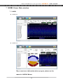
1
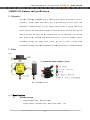
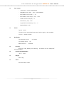
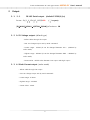
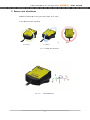
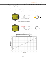
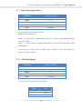
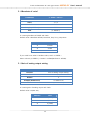
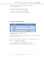
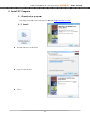
3-A Axis Acce elerometter & 3-A Axis Gyro o MSE M ENS S-GY Y User's Ma anuall 09-3,, Yangno-ri, Bib bong-myeon, Hwaseong-si, H Gy yeonggi-do, Ko orea [445-842] http://www.daas-co.com T) +8 82-31-356-3541, F) +82-31-3556-3572 3-axis accelerometer & 3-axis gyro sensor MSENS-GY User’s manual Before using 1. This equipment is 3-axis, use the following information to be checked. 2. Check used to test the power. 10 ~ 30Vdc voltage is used. In noisy environments must be connected to the ground. 3. Connect the correct cable to determine the index, please. Incorrect connection may result in damage of the equipment. 4. 1 year warranty on this product. Applications 1. Navigation of vehicle, Speed detecting. 2. Earthquake Detection, Tilt measurement 3. Motion Control 4. Virtual Reality System Application 5. Measurement of the bridge safety inspection 6. vibration of Facilities, equipment and structures detection 2 3-axxis accelerom meter & 3-axis gyro sensor MSENS NS-GY Useer’s manuaal 1MSENS-GY fea atures an nd specifficationss 1-1Features The ma ain advantag ge of MSEN NS-GY is to measure motion aboutt all directio ons, and it is possible to outpu ut angle vaalue about gyro. It provides p beest solution about anyy applica ation by Miccroprocessorr. The user settings can n be stored d in internal memory of o sensor. (direction, the t analog o output range e, the sensor ID, specifyy the initial value, v etc.) In n addition, because the sensor RS-485 com mmunication n can be co onnected to o more than n 1Km, a line can be e connected d to Maximu um 254 sensors. Core ssensor shield d to prevent penetra ation through the stro ong noise, motors, ettc. can be used in strong s noise e environ nment. Senso ors have beeen molded silicone s insid de can be ussed in inclem ment weathe er 1-2Size Pic P 1.1 MSEN NS-GY size 1-3Spec cifications s Measu uring Range e Angle( Roll,Pittch, Yaw) : ± ±180 full-ran nge Angular veloccity. ( Roll,Pittch, Yaw) : ±250, ± ±500, ±2000 〬/seec 3 3-axis accelerometer & 3-axis gyro sensor MSENS-GY User’s manual Core sensor - 3 axis gyro + 3 axis accelelometer. - Range(Roll ,Pitch, Yaw, 〬/sec) : ±250 (default) - Bias Stability In-Run(°/hr) : < 12 - Bias Stability Over Temp(〬/sec) : <±0.5 - Scale Factor Accuracy(%) : <1 - Resolution(〬/sec) : 0.02 - Angle Random Walk(°/sq-rt hr) : <3 - Bandwidth(Hz) : 100 Power Typical : 12Vdc The sensor was unregulated power (10~30Vdc) supply is also available. Current : <50mA at 12Vdc Resolution Gyro angular velocity : 8.75 mdps Gyro Angle output : 0.1° Max total error : 0.25%(FS) Housing IP66, PVC Case, Water-proof Housing : The Sensor can be waterproof silicone molding. OperationgTemperature -20 to .. +85°C Weight about 68g Cable 6P Shield cable, 50CM 4 3-axis accelerometer & 3-axis gyro sensor 2 MSENS-GY User’s manual Output 2-1 2-1 RS-485 Serial output (default 115200,8,1,n) format : Ex) [101234451923]54CR (’’ is space) [IDMODEX(ROLL)Y(PITCH)Z(YAW)]+Checksum+ CR 2-2 0~5V Voltage output. (default type) - Yellow cable through the output. - User can change output axis by serial command. - Lowest range : 100mV (It can be changed between 100 ~ 1,000mV by order made) - Highest range : 4900mV (It can be changed between 4000 ~ 4900mV by order made) - Center Value : middle value between Low output and High output 2-3 4~20mA Current output .(order made) - Yellow cable through the output. - User can change output axis by serial command. - Lowest range : 4.32mA - Highest range : 19.68mA - Center Value : 12mA. 5 3-axxis accelerom meter & 3-axis gyro sensor MSENS NS-GY Useer’s manuaal 3 Se ensor axis directions MSESE--GY measure es 3-axis gyrro sensor (Ro oll, Pitch, Yaw). 3-axis directions d are following. X Y ( Pitch ) Z ( Yaw ) h axis direction Pic .3-1 Each Pic .3-2 3-axis dirrections 6 (Roll ) 3-axxis accelerom meter & 3-axis gyro sensor 4 MSENS NS-GY Useer’s manuaal Wiriing MSESE--GY for a sixx-stranded s hielded cablle is used. Supply voltag ge 2-line, RS S-485 2-line, mA output consists of a line. RS-4 485 and the e unused lin ne of mA ou utput ot touch the e other by cu utting the ca able must be insulated. When using g RSdoes no 485 disstance is lo onger than 50M 120 Ohm O termin nation is reecommended d. In addition, if multip ple sensors connected in parallel to use in the termina ation resistorrs. 4-1RS-485 Wiring. RS-485 communications can n be read sensor value when thee one or more m onnected in parallel to a line. Howe ever, caution n this time, each sensorrs can be co sensorr's ID to be different, co ontinuous da ata read (# READ) R instrucction, such as a ID and to o answer all the sensorss, regardless of instructio on should n not be used. And when you use multiple sensorrs to allow sufficient s pow wer supply w wiring should be ned. design Pic 4.1 Cable Index Pic 4.2 RS-4 485 Parallel connection c diagram d 7 3-axxis accelerom meter & 3-axis gyro sensor MSENS NS-GY Useer’s manuaal 4-2 Analog Wirring The an nalog output is voltage((default) or current c output. Outp put axis of analog is chaanged by user command d. The defau ult output axxis is Yaw. (mV) outt V GND Pic 4.3 3 Analog of voltage wiring A GND 4 Analog of current c wirin ng Pic 4.4 Accelera ation VS Vo oltage outp put 8 3-axis accelerometer & 3-axis gyro sensor MSENS-GY User’s manual 5MSENS-GY Communication Commands First of all the transfer of 'CR' will be sent by appending. Example> In case ID = 1 , MODE = 0, Send format : <1 Command> + Check-sum + CR Receive format : [1 0 “Pich”“Roll”“Yaw”] + Check-sum + CR Example of calculation checksum) <1 START> = ‘<‘ XOR ‘1‘ XOR ‘‘ XOR ‘S’ XOR ‘T’ XOR ‘A’ XOR ‘R’ XOR ‘T’ XOR ‘>’ = CHECK_SUM Command 데이터출력 Echo CMD VALUE Function Data output <1> x x 1time data [1 0 1234 45 4567] <1 START> [1 START] x Continues [1 0 1234 45 4567] data 설정명령어 <1 STOP> [1 STOP] x Stop output <1 ID 254> [1 ID 254] 1~254 ID Change <1 SPEED 1> [1 SPEED 0] 1, 2, 3 baudrate <1 MODE 0> [1 MODE 0] Angle:0, MODE angular change velocity :1 <1 SCALE 1> [1 SCALE 1] <1 ANALOG 2> [1 ANALOG 2] GY: 1,2,8 Full Scale AC: 2,4,8 Setting X:0, Y:1, Z:2 Analog 출력 축 설정 <1 OFFSET 3.5> [1 OFFSET 3.5] Voltage(mV) Analog output axis offset <1 SPAN 1.05> <1 CALI> [1 SPAN 1.05] Scale Analog output Factor span [1 CALI 12 34 56] x Gyro Bias Calibration <1 INIT> [1 INIT] x Set to YAW 0 <1 SAVE> [1 SAVE] x Save Setting <1 RESTORE> [1 RESTORE] x Default setting values return <1 VER> [1 VER MSENS-GY 01.00] x Version information Table 5.1 Command 9 3-axis accelerometer & 3-axis gyro sensor MSENS-GY User’s manual 5-1 One-time data output COMMAND <1> Function One-time data output Example (id=1) <1> Echo 없음 Output [1 0 1234 45 1923] Attention) All of following example is for ID 1, MODE 1. Mode ’0’ Output data is applied Kalman filler. It is good for slow measurement and more correct value. Unit is mg/DIGIT. [10123445 1923] ex) 1234 = 1234 mg = 1.234 g ID=1, MODE=0, X=1234, Y=45, Z=1923 Mode ‘1’ Output data is not applied Kalman filler. It is good for fast and more roughly measurement. Unit is mg/DIGIT ex) 1234 = 1234 mg = 1.234 g Output is include scale value. [1 11 522 2345 1253] ID=1, MODE=1 ,SCALE=1,X=522, Y=2345, Z=1253 (Attention) When the Mode is ‘1’, output interval is 10msec. 10 3-axis accelerometer & 3-axis gyro sensor MSENS-GY User’s manual 5-2 Continuously data output COMMAND <1 START> Function Continuously data output Example (id=1) <1 START> Echo [1 START] Output(mode=0) [1 0 1234 45 1923] After send command, send the save command. If don’t send save command, lost command when turn off. Attention) Do not send ‘START’ command to more 2 device with RS485. 5-3 Stop data output COMMAND <1 STOP> Function Stop data output Example (id=1) <1 STOP> Echo [1 STOP] If output speed is high, Send ‘STOP’ command several times until data output is stop. 11 3-axis accelerometer & 3-axis gyro sensor MSENS-GY User’s manual 5-4 ID Setting COMMAND <1 ID “New ID”> Function ID Setting and check Default 1 Example (new id=123) <1 ID 123> Echo [1 ID 123] MSENS-GY has own ID number (1~254). Default ID number is ‘1’. You want know ID number, do following Connect to pc on RS45 and send <0>. The return value is ID,, MODE , X,Y,Z. [1 0 1234 45 1923] It mean is ID=1 , MODE=0, X=1234, Y=45, Z=1923 (Attention) After send command, send the save command. If don’t send save command, lost command when turn off. 12 3-axis accelerometer & 3-axis gyro sensor MSENS-GY User’s manual 5-5 Data output type setting COMMAND <1 MODE “VALUE”> Function Data output type setting Value 0,1 Default 0 Example (new MODE=1) <1 MODE1> Echo [1 MODE1] It is setting data output type and check. Default value of MODE is ‘0’ MODE 0 : Output data is applied Kalman filler. It is good for slow measurement and more correct value. MODE 1 : Output data is not applied Kalman filler. It is good for fast and more roughly measurement. If you wand know what is the set MODE, Send <1 MODE>. Then return value is [1 MODE 0]. It mean is MODE 0. 5-6 Full Scale Setting COMMAND <1 SCALE “VALUE”> Function Full Scale Setting Value 1, 2, 8 Default 1 Example (NEW SCALE=8) <1 SCALE 8> Echo [1 SCALE 8] It is to set full scale of gyro sensor and check. SCALE DPS 1 ±250 2 ±500 8 ±2000 13 3-axis accelerometer & 3-axis gyro sensor MSENS-GY User’s manual Default value is 1(±250 DPS) If you want know what is SCALE value, send <1 SCALE> Return value is [1 SCALE 8]. It means the scale value is 8(±2000 DPS) Output unit is always mdps. 5-7Data output interval COMMAND <1 INTERVAL “VALUE”> Function Data output interval Value 10 ~ 1000 Default 100 Example (INTERVAL=10mS) <1 INTERVAL 10> Echo [1 INTERVAL 10] It is setting data output interval and check. The setting unit is msec. Range is from 10[msec] to 1000[msec]. Setting step is 10[msec]. Default value is 100 [msec. But, interval is only 10[msec] when MODE 1. Send Command : <1 INTERVAL> Return value : [1 INTERVAL 10] It mean is 10[msec]. 14 3-axis accelerometer & 3-axis gyro sensor MSENS-GY User’s manual 5-8Baudrate of serial COMMAND <1 SPEED “VALUE”> Function RS485 Baudrate of serial Value 1, 2, 3 Default 1 Example (SPEED=2) <1 SPEED 2> Echo [1 SPEED 2] It is setting baudrate of RS485 and check.. Default value is Baudrate:115200, Data bit:8, Stop bit:1, parity:None SPEED BAUD RATE 1 115200 2 57600 3 38400 If you wand know what is baudrate value, send <1 SPEED >. Return value is [1 SPEED 1]. It mean is 115200(baudrate is 115200). 5-9Axis of analog output setting COMMAND <1 ANALOG “VALUE”> Function Axis of analog output setting Value 0, 1, 2 Default 2 Example (ANALOG=0) <1 ANALOG 0> Echo [1 ANALOG 0] It is setting axis of analog output and check. Default value is 2(Yaw axis). ANALOG AXIS 0 X (ROLL), 1 Y (PITCH) 2 Z (YAW) 15 3-axis accelerometer & 3-axis gyro sensor MSENS-GY User’s manual If you want know what is output axis of analog. Send <1 ANALOG>. Return value is [1 ANALOG 0]. Analog value is deferent depend on FULL SCALE. ±2g : -2g : 0.5V, 0g : 2.5V, +2g : 4.5V 출력. ±8g : -8g : 0.5V, 0g : 2.5V, +8g : 4.5V 출력 4~20 mA : 0.5V = 5.6 mA, 2.5V = 12 mA, 4.5V = 18.4 mA 5-10Analog output offset setting COMMAND <1 OFFSET“VALUE”> Function Analog output offset setting Value Real Default 0 Example (OFFSET=3.5) <1 OFFSET 3.5> Echo [1 OFFSET 3.5] It is setting for analog output offset and check. Default value is 0[mV]. It has two kind of type. One of them is voltage, other one is current. It is setting by order made. Default is voltage. If sensor is current output type and setting value is 1, output is change to 3.2uA up. Example) <1 OFFSET 3.5> 3,5mV up. <1 OFFSET -12.5> -12.5mV down. If you want know what is offset setting value, send <1 OFFSET>. Return value is [1 OFFSET -12.5]. It means offset setting value is -12.5 mV. 16 3-axis accelerometer & 3-axis gyro sensor MSENS-GY User’s manual 5-11 Span of analog output setting COMMAND <1 SPAN“VALUE”> Function Span of analog output setting Value Real Default 1 Example (SPAN=1.00452) <1 SPAN1.00452> Echo [1 SPAN1.00452] It is setting for span of analog (mV or mA) output and check. Default value is 1. Example) <1 SPAN 1.00452> Voltage output is FULL SCALE * 1.00452 <1 SPAN 0.9987> Voltage output is FULL SCALE * 0.9987 If you wand know what is SPAN setting value, Send <1 SPAN. Return value is [1 SPAN0.9987 5-12GyroBiasCalibration COMMAND <1 CALI > Function Gyro Bias Calibration Example <1 CALI> 응 답 [1 CALI 123 24 43] It is to calibration for bias of core gyro sensor It needs about one second. Do not change except if you know this function well. Return value is [1 CALI123 24 43]. It means X-bias : 123 , Y-bias : 23 , Z-bias : 43 5-13Z(Yaw) 0 Degree Initial Setting COMMAND <1 INIT> Function 1-1Z(Yaw) 0 Degree Initial Setting Example <1 INIT> Echo [1 INIT] 17 3-axis accelerometer & 3-axis gyro sensor MSENS-GY User’s manual It is to change the value of angle of Yaw to 0. It is same that the blue-line is connected red-line(+V) very sort time. 5-14Save setting values COMMAND <1 SAVE> Function Save setting values Example <1 SAVE> Echo [1 SAVE] It is to save to EEPROM setting values. 5-15Conform the S/W version COMMAND <1 VER> Function Conform the S/W version Example <1 VER> 응 답 [1 VER MSENS-GY 01.00] If you want know what is S/W version, send <1 VER> Return value is [1 VER MSENS-AC 01.0]. 5-16Return all setting values to default COMMAND <1 RESTORE> Function Return all setting values to default Example <1 RESTORE> Echo [1 RESTORE] All setting values in EEPROM are return to default except baudrate. 18 3-axxis accelerom meter & 3-axis gyro sensor MSENS NS-GY Useer’s manuaal 6 Install PC Pro ogram 6-1Do ownload pc p program m The settup program m is technica l board of website( w http p://www.das--co.com). 6-2 In nstall Double clicck the icon of o setup. Input the install path. Finish 19 3-axxis accelerom meter & 3-axis gyro sensor MSENS NS-GY Useer’s manuaal 7 MSEN NS-Viewer Main window w 7-1MAIN MSENS-AC MSENS-GY Iff you wan nt more in nformation n about program, p please see e the m manual of MSENS-V Viewer. 20 3-axis accelerometer & 3-axis gyro sensor MSENS-GY User’s manual The information contained in the product manual without prior notice for quality improvement. Described above are subject to change copyright of all content on DAS CO.,LTD And reproduced without prior consent, and may not be distributed by. DAS Co., Ltd Copyright ⓒ by Das Co.,Ltd. All Right Reserved Website : www.das-co.com Phone No : +82 - (0)31 - 356 - 3541 FAX No : +82 - (0)31 – 356 - 3572 e-mail : Address : 09-3, Yangno-ri, Bibong-myeon, Hwaseong-si, Gyeonggi-do, Korea [email protected] [445-842] 21