1
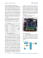
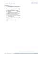
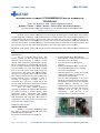
ISSN: 2277-9655
2277
[Sakhare, 2(4): April, 2013]
IJESRT
INTERNATIONAL JOURNA
JOURNAL OF ENGINEERING SCIENCES
ENCES & RESEARCH
TECHNOLOGY
Time for Action to End Violence against Women
Radhika S Sakhare *1, Nikita V Hebbar 2, Sailee D Patil 3, Harshada M Wasade 4
*1, 2,3,4
Veermata Jijabai Technological Institute (VJTI), Mumbai
Mumbai-400019,
400019, Maharashtra, India
[email protected]
Abstract
Incidents of crime against women have been increasing at an alarming pace in Indian cities, most common
incidents being rape, kidnapping, sexual harassment and eve teasing. While a lot of legal and NGO authorities are
coming forward with their plans to prevent such crimes and make the cities safer for women, in this age of
technology, mobile
ile phone is one gadget almost everyone uses to keep in touch with family and friends. Women can
definitely make good use of inbuilt technology to use their mobile phones as a SOS tool in case of emergencies. This
paper describes a system using which a wom
woman
an in distress can call for help with the click of a button.
Keywords: Crime
rime against women, help with the click of a button, Interactive Voice Response System, mobile SOS
tool.
Introduction
This is a personal safety service that
instantly connects you with your safety network and
authorities in an emergency. It employs a central
database which contains the registered user’s profile.
When in need of help or emergency the user can dial
the service number
umber and select various alert options by
pressing a number key. This action sends a DTMF
tone to the IVR system which then executes the
selected service. The options will include sending a
message to the emergency contact enlisted in the data
base, sendingg notification to the police, sending users
location through service providing or GPS or
recording an emergency message. This is a
convenient and easy-to-use
use system which will
provide instant notification to family and concerned
authorities without drawing much attention.
There are many mobile applications
operating on platforms like android, iOS, Blackberry
etc. which are aimed at women’s security. These
applications require Smartphone and internet
connections. However, everyone is not acquainted
with Smartphone
tphone and using apps. This system is
designed for a wider range of users as it requires just
basic phone with cellular services.
•
•
•
•
EGSM 900 MHz, DCS 1800 MHz and
PCS1900 MHz working on GSM networks in
all countries across the world.
wor
Two serial ports for interfacing with
computer.
Speaker and Headphone jacks - so that you
can send DTMF signals or play recording
like an answering machine.
Short Message Service - so that you can send
small amounts of data over the network
(ASCII or raw
aw hexadecimal).
The sim card corresponding to the service
number is placed in the sim 300 sim card slot.
The module is connected to a microcontroller
through Max232 interface for serial
communication. When a user calls the service
number, the ring is detected
dete
and using AT
command ATA the call gets received
automatically.
With the help of AT
commands the user’s number is available.
Elements of the System
SIM300 GSM Module
SIM300 is a Tri-band
band GSM/GPRS engine
that works on frequencies EGSM 900 MHz, DCS
1800 MHz and PCS1900 MHz.
Key feature of sim300 used in our project are:
•
•
http: // www.ijesrt.com
(C) International Journal of Engineering Sciences & Research Technology[863-866]
Technology
ISSN: 2277-9655
[Sakhare, 2(4): April, 2013]
Dual Tone Multi Frequency Technology
I. Dual tone multi frequency technology uses
mixture of two pure tones to represent a digit pressed
on the phone keypad..The DTMF keypad is a 4×4
matrix, with each row representing a low frequency,
and each column representing a high frequency. On
pressing a single key (such as 1), a sinusoidal tone is
sent for each of the two frequencies (697 and
1209Hz). The tones are sent to a DTMF decoder
which converts these tones into corresponding 4 bit
BCD number. In our project, the user selects alert
options by pressing a key on the keypad. Received
DTMF tone is then decoded and processed by the
microcontroller to identify the alert option selected.
II. M-8870
M-8870 operating function include a band split filter
that separates the high and low tones of the received
pair, and a digital decoder that verifies both the
frequency and duration of the received tones before
passing the resulting 4-bit code to the output bus.
of registers providing enhanced features and
accelerated port access or the legacy group of
registers. We use GPIO pins to take the data from
DTMF decoder and then transmit it to computer via
UART1. The ARM7TDMI-S processor also employs
a unique architectural strategy known as THUMB,
which makes it ideally suited to high-volume
applications with memory restrictions, or applications
where code density is an issue. The key idea behind
THUMB is that of a super-reduced instruction set.
Essentially, the ARM7TDMI-S processor has two
instruction sets:
1. The standard 32-bit ARM instruction set.
2. 16-bit THUMB instruction set.
Microcontroller ARM LPC2148
In our project we have used ARM processor
LPC2148. A 128-bit wide memory interface and
unique accelerator architecture enable 32-bit code
execution at the maximum clock rate. For critical
code size applications, the alternative 16-bit Thumb
mode reduces code by more than 30 % with minimal
performance penalty. Due to their tiny size and low
power consumption, the LPC214x family is ideal for
applications where miniaturization is a key
requirement, such as access control and point-of-sale.
The CPU operating voltage ranges from 3.0 V to 3.6
V (3.3 V ± 10 %) with 5 V tolerant I/O pads. The
ARM architecture is based on Reduced Instruction
Set Computer (RISC) principles, and the instruction
set and related decode mechanism are much simpler
than those of Micro-programmed Complex
Instruction Set Computers. We use two UARTs of
LPC2148, one for interfacing with GSM module and
other with computer. Microcontroller communicates
with GSM module through RXD0 and TXD0 and
with computer through RXD1 and TXD1. Every
physical GPIO port is accessible via either the group
MAX 232 Serial Interface
A standard RS-232 interface for computer
uses voltage levels ranging from -12V to +12V. In
order to adjust the microcontroller voltage levels
(TTL standards) for compatibility with the computer,
voltage level converters are necessary. Max-232, is
an integrated circuit, that provides this necessary
adjustment.
http: // www.ijesrt.com
Block Diagram
(C) International Journal of Engineering Sciences & Research Technology[863-866]
ISSN: 2277-9655
[Sakhare, 2(4): April, 2013]
Operation
A woman in distressed emergency situation
dials the service number. This call is recognized by
the GSM module used in the IVR system and the
appropriate
signal
is
transmitted
to
the
microcontroller through the Tx pin of GSM module.
The microcontroller signals the GSM module to
receive the call through Rx pin of the GSM module
and also asks the GSM module to transmit the user
number. After a brief welcome message, the IVR lays
out different options like sending an SOS alert to
family, to the police , sending user location etc. The
woman selects one of the options by pressing the
relevant number. This results in DTMF tones being
generated by the user . These tones are received by
the GSM module and are sent to the microcontroller
via the DTMF decoder. The microcontroller forwards
these DTMF signals to the computer via UART. The
front end program running on the computer (like
Visual basics , Python etc) will search for the number
stored in the database which is the back end software
(like MySQL, MsAccess etc.) and retrieve relevant
information.
The
computer
signals
the
microcontroller to send appropriate signals to the
GSM module to terminate the call and to execute the
selected
action.
Software
AT Commands for GSM Module
The controlling device controls the GSM
module by sending AT Command via its serial
interface. The "AT" or "at" prefix must be set at the
beginning of each command line. The AT command
set implemented by SIM300 is a combination of
GSM07.05, GSM07.07 and ITU-T recommendation
V.25ter and the AT commands developed by
SIMCOM.
The AT commands used are:
COMMAND
AT+CLIP=1
ATD><n>
ATH
ATS0
AT+CMSS
USE
For accessing caller number
Originate call to phone number in
current memory
Disconnect existing connection
SET NUMBER OF RINGS
BEFORE
AUTOMATICALLY
ANSWERING THE CALL
SEND SMS MESSAGE FROM
STORAGE
VB and Ms Access
Microsoft access is used to store the profile of the
registered users. The profile contains the emergency
contact, address and other personal details. Every
users profile is tagged by the user phone number.
http: // www.ijesrt.com
Thus when the call for help arrives, the system scans
the database for the caller’s phone number and
corresponding profile is forwarded to the authorities
Programs can be written in Visual Basic to access
Microsoft access databases. Some programming
concepts such as subroutines and looping along with
knowledge of databases and SQL may be required to
write programs to link Microsoft Access database to
Microsoft Visual Basic code. The ADODB object is
used to create a connection to the database and access
the records using ADODB .connection and ADODB
recordset APIs respectively. SQL is used to search
the database for records that match the information
provided as parameters to the subroutines. Data in the
records can also be manipulated in the Visual Basic
program code.
Microcontroller Programming
Microcontroller waits for the GSM module to
transmit the data of incoming call using UART0.
Then it receives the call and transfers the number to
computer using UART1. Microcontroller waits for
the DTMF decoded binary data on PORT0 and upon
receiving validation signal; it sends the signal to
computer via UART1. UARTs have Receiver Buffer
Register and Transmit Holding Register for 8-bit read
and write operation (U0RBR, U0THR, U1RBR, and
U1THR). For control and status operation, it has
U0LCR U0LSR, U1LCR, and U1LSR for UART0
and UART1 respectively. To enable transmission, we
use U0TER and U1TER. Upon receiving the data in
the buffer, it issues the interrupt in Interrupt Enable
Register U0IER and U1IER. To read the value of
input GPIO pins we use IOPIN register. To set the
value of output pins we use IOSET register. To make
the given port pins input or output, register IODIR is
used. Here, WinARM is used to write the
microcontroller program and get the binary file to
burn into the microcontroller through USB
programmer.
Conclusion
This paper reviews the interactive voice
response system which is helpful for women in the
incidents of crime. The key objective is to develop a
low cost system which can store the data of the
members in the particular locality and provide
immediate alert in case of crime against women. This
provides women security.
Acknowledgement
The authors would like to thank our project
guide, Prof. A. Jeykumar, Professor, Electrical
Department, V.J.T.I, to motivate us for this
innovative project and also for her support in the
overall development of the product.
(C) International Journal of Engineering Sciences & Research Technology[863-866]
[Sakhare, 2(4): April, 2013]
ISSN: 2277-9655
References
[1] LPC214x datasheet user manual by Philips
Semiconductors.
[2] AT commands manual by Simcom.
[3] http://www.engineersgarage.com/articles/gs
m-gprs-modules?page=1
[4] GSM Simcom’s SIM300 user manual.
[5] H.S.Kalshi,
Electronics
Instrumentation,Tata, Mc Grawhill.
[6] http://www.functionx.com/vbaccess/Lesson
01.htm
[7] http://raviyp.in/index.php/embedded
[8] David E.Simon, Programming in embedded
‘C’, Pearson Education.
[9] D.Roy Chodhary, Shile B.Jani, Linear
integrated circuits.
[10] http://www.datasheet4u.net/
[11] http://www.alldatasheet.com/
http: // www.ijesrt.com
(C) International Journal of Engineering Sciences & Research Technology[863-866]