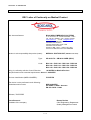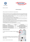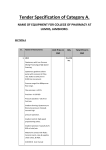
1
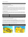
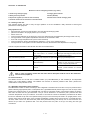
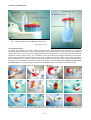
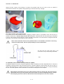
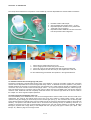
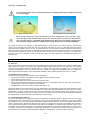
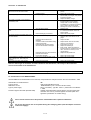
2003/09 Rev. E1 USMAN2012-E
MEDICAL SUCTION UNIT BOSCAROL
OB 2012 FA
OB 2012 LINER
USER MANUAL
OB2012FA with autoclavabile jar
OB2012FM with disposable jar
MANUFACTURED BY:
www.boscarol.it
1 - 19
2003/09 Rev. E1 USMAN2012-E
1. Caution notice.
PLEASE READ BEFORE THE USE!
•
•
•
•
•
•
•
•
•
•
Before the use of the OB2012 Suction Unit, please read this instruction manual carefully.
The OB2012 Suction Unit is an independent active medical device. Laws in force restricts this device to sale,
distribution, and use by-or on the order of a physician, emergency medical technician, or other medical practitioner
Do not use the suction unit in presence of flammable agents or anesthetics.
Due to the nature of the unit's use, all precautions must be taken to ensure the unit's reliability (cleaning, storage,
environmental conditions, etc.).
In case of suction without the jar and/or the protection filter, or in the case of a suspicion that any substances are
penetrated in the unit, send immediately the suction unit to the service center for the control and the
decontamination (see the 6. chapter).
Before cleaning the unit and/or to proceed to the maintenance of the device, disconnect the unit from the wallbracket or from the recharging cable. Do not put the unit in water or fluid substances to avoid the damage of the
device.
Do not suction substances for disinfecting or cleaning fluid in the unit, without the protection filter and/or the jar.
These substances can damages the internal parts of the unit.
There are no serviceable components in the unit, refer always to trained service people.
Use only original and authorized spare parts furnished from the manufacturer (Boscarol Emergency Systems), to
have always the maximum security and efficiency of the device.
Do not alter the mechanical and/or electrical parts on the wall-bracket unit. The change and/or the alteration of
parts on this unit can be very dangerous for the security retention. Never change, release and/or modify the spring
on the wall-bracket. This part is very important for the security in the case of very high negative acceleration force
(up 10g negative force).
Internal battery:
•
•
•
•
•
•
Reconnect the suction unit for charging after every use. The charging switch on automatically, when the unit is put
on the wall bracket, when it is connected with the external cable to a 12VDC source or with the optional battery
charger (from the main supply). On receipt of the suction unit from the manufacturer, recharge the unit at least for
24 hours.
The correct use and recharging of the internal battery guarantees a typical lifetime of 2-3years. After this time it is
better to change the internal battery.
If it is impossible to recharge the battery (in case of not use for long time, for example) verify every month the
good operation of the unit and recharge the internal battery for not less of 24 hours.
Never forget to store the suction unit after the use, without to have recharged the battery. When sealed acid battery
voltage fail following a "deep discharge", have to be replaced.
The replace of the internal battery is not possible from the user and/or customer. Refer always to the service
authorized.
During the recharging time verify the light on the front side. On the charging phase the colour of the light is red,
and switch on green colour when the battery is completely recharged.
Security inspection:
The device have to be checked form the service authorized people, at less every 24 mounth from the receipt date of
the suction unit.
2 - 19
2003/09 Rev. E1 USMAN2012-E
Index.
1.
Caution notices.
2.
Introduction.
2.1 Package contents.
2.2 General description.
2.3 Contra-indication use.
2.4 Technical features of the device.
2.5 Special storage and operating instruction.
2.5.1 Storage requirements.
2.5.2 Operating instructions.
2.5.3 Operating in the rain.
2.6 Guarantee.
3.
Description of the device.
3.1 Controls, indications and check panel.
3.1.1 Mechanical controls.
3.1.2 Lighting indications.
3.1.3 Test of the device.
3.2 Collect container (Jar).
3.2.1 Reusable collect container.
3.2.2 Protection filter.
3.2.3 Reusable collect container with disposable liner.
3.3 Suction catheter Jankauer and/or Finger-typ joint connector.
3.4 Power and recharging of the battery.
4.
Maintenance and reuse.
4.1 After use of the suction unit.
4.2 Reusable collect container.
4.2.1 Decontamination of the collect container.
4.2.2 Replacing of the protection filter.
4.3 Reusable collect container with disposable liner.
4.4 Discharg of the contamined and/or disposable parts.
4.5 Cleaning of the unit.
4.6 Recharging of the unit.
4.7 Verify of the battery capacity.
4.8 Security on the device.
4.9 Demolition and out of order.
5.
Accessories and spare parts, optionals.
5.1 Code and index.
6.
Service.
7.
Trouble shooting.
8.
Technical data and report to the international law.
8.1 Classification on the MDD 93/42/EEC.
8.2 Size and dimensions.
8.3 Technical features of the device.
8.4 Power supply.
8.5 Enviromental condition.
8.6 Technical data of the protection filter.
8.7 Simbology.
8.8 Declaration of the conformity.
8.9 Return-traceability of the suction unit (EN46001:1996 – ISO13485:2002).
3 - 19
2003/09 Rev. E1 USMAN2012-E
2. Introduction.
2.1 Package contents
OB2012 FA Medical suction unit:
•
N.1 Suction unit OB 2012 ready to use.
•
n.1 1000cc reusable collect container with integrated overfill valve.
•
N.1 protection filter (type AIR SAFETY 60mm).
•
N.1 external recharging cable 4 poles.
•
N.1 sterile Jankauer suction catheter complete with suction tube.
•
N.1 red carrying bag.
•
N.2 spare fuse of T15A.
•
N.1 user manual.
OB2012 LINER Medical suction unit:
•
N.1 Suction unit OB 2012 ready to use.
•
N.1 1000cc reusable collect container with disposable liner complete with integrated filter.
•
N.1 external recharging cabel 4 poles.
•
N.1 sterile Jankauer suction catheter complete with suction tube.
•
N.1 red carrying bag.
•
N.2 spare fuse of 15AT.
•
N.1 user manual.
Optional (only if needed by customers):
•
Battery charger from the main supply (100÷230Vac 50-60Hz).
•
Set patient silicon tube with end piece Finger-typ.
•
Wall bracket with electrical connections for the recharging in the vehicle (12Vdc).
•
Blue colour carrying bag.
2.2 General description.
The OB 2012 FA/LINER is a portable, battery operated medical suction unit used to clear the upper airway and restore
breathing either spontaneously or forced. The unit is suitable for use in paramedic services, in a doctor’s office or for
home medical care. The OB2012 is powered by sealed acid battery capable of driving the unit at full power for about
40 minutes (±10%). The internal battery (12V) is recharged with a special inside electronical circuit (DC-DC converter)
which is activated by the connection to the vehicle electrical system (12Vdc). Upon request the unit can be fitted with a
special charging/retention shelf (wall-bracket OB20WB).
2.3 Contra-indication use.
Do not use the suction unit OB2012 for the thorax drainage.
2.4 Technical features of the device.
The OB2012 Suction unit is manufactured in accordance with the laws in force, and is engineered for a very easy use
during the emergency situations. The most benefits are these:
•
Very strong ABS antischock chassis, with special design, easy to clean and protected against the penetration of
fluid subsatances and water.
•
Easy way to replace the disposable and/or maintenance parts.
•
Dual mode battery charger: with the external cable (with cigarette lighter socket) or with the optional wall-bracket.
•
It is possible to recharge the battery from a main supply with a optional battery charger (230VAC or 100VAC).
•
When the unit is put on the wall bracket or at the external cable, the unit doesn't use the energy from the internal
battery.
•
Easy switch on of the device with a protected switch accessible also with glove.
•
Realtime value of depressure on the double range analogic gauge (mbar/kPa).
•
Vacuum regulation from minimum to maximum without step (linear). It is possible to set any value from a
minimum of -800mbar (-80kPa).
•
Very high powerful pump motor (about 30LPM).
•
High affidable system with double piston pump.
•
Realtime indication of battery autonomy with light indicator (4 steps).
•
Realtime indication of recharging with green colour led.
•
All controls are on the front side of the unit, to be used also when the unit is fixed on the wall-bracket.
4 - 19
2003/09 Rev. E1 USMAN2012-E
2.5 Special storage and operating instructions.
2.5.1 Storage and transport conditions.
The unit must be stored in a dry room and protected against high value of temperatures. When not utilized for a long
time period, the unit must be checked every month and recharge the battery for not less of 24 consecutive hours. The
temperature range for the right storage is between -25°C and +60°C (degrees C), and the humidity range is f rom 10%
to maximum 80% (relative value, not condensed) in order to prevent sudden discharge of the internal batteries. The
storage is possible only with the original package, which avoid damage and discharge of the internal batteries. When
disassembled for cleaning operation, see this manual for the right operation. Atmospheric pressure range:
700/1060hPa (700/1060mbar).
2.5.2 Operating instructions.
While in operation, the unit should not be exposed to extreme temperature fluctuations. Normal operations should only
take place between -10°C and +50°C. The acceptable humi dity range is between 20% and 90%UR. If the unit is
operating correctly outside the displayed values, these values in relation to suction, pressure and charging could be
distorted. Never operate the unit in temperatures above +60°C. Be aware that if the unit is operating at al titude over
2,500 meters above NN, the pressure value can slightly decrease. This is caused by the decrease in the atmospheric
pressure. We suggest recharging the unit with temperature range between 15 and 30°C. Atmospheric pressure range :
700/1060hPa (700/1060mbar).
2.5.3 Operating in the rain.
The OB2012 FA/LINER is protected against the rain penetration. Otherwise the unit should never be operated by very
heavy rain. Whether during operation or storage the unit must always stand upright. In the event that water gets into
the side compartments suction unit clear and then dry throughly.
2.6 Guarantee.
The Boscarol Emergency Systems offers for the OB2012 FA e OB2012 LINER a 36 months guarantee from the date of
the first purchase. Boscarol Emergency Systems, guarants that each new OB2012FA and OB2012 FM products is free
of defects in material and workmanship. From this guarantee are excluded: the collect container and/or the liner, the
external cable for the recharging, the internal battery, the normally wear and tear of the unit, discoloration,
colour alteration and all the other aesthetical irregularity which not produced degradations the operations of the
unit. If returned to Boscarol Emergency Systems, the factory will arrange for repairs or replacement within the terms of
this guarantee. The defective device should be decontamined and returned properly packaged, with included writing
note about the defect of the unit. All costs for the shipment (postal and/or courier) are to sender expense.
The guarantee shall not apply to any Boscarol product which has been repaired by otherone other than authorized
Boscarol emergency Systems representative, or altered in any way so as, in Boscarol's judgment, to affect its safety or
efficacy, nor which has had the serial number altered, effaced or removed. Neither shall this guarantee apply to any
Boscarol product which has been connected or charged otherwise than in accordance with the instructions furnished by
Boscarol.
Conditions for the validity of the guarantee
For the validity of the guarantee, the customer shall produce this documentation:
•
Copy of the invoice and/or the purchase declaration with the serial number of the unit and the date of the
purchasing.
For all legal purposes, Boscarol Emergency Systems is responsible for the security, operation and affidability only if:
•
•
•
All technical operations, repairs, modify and mainenance actions are executed from the Boscarol Emergency
Systems and/or from the authorized service center.
The device is right used, as indicated in this user manual.
The electrical systems where the suction unit is connected, is performed on the international norms and national
law in force.
Refer to above descripted, Boscarol Emergency Systems is not responsible for accidental or indirectal damage resulted
by not authorized modify, not authorized repair, not authorized technical intervents, or when any parts of the unit are
damaged in case of incident, accident, bad use and/or misuse. On the OB2012 suction unit doesn't is it other
guarantee (limited, etc.) and/or other ability not descripted on the present user manual. Jurisdiction for legal
department is Bolzano - Italy.
5 - 19
2003/09 Rev. E1 USMAN2012-E
3. Description of the device.
3.1 Controls, indications and check panel.
All the controls of the suction unit are on the front side of the unit. The control of the unit is possible also when the unit
is fitted on the wall-bracket and/or with the carryng bag.
3.1.1 Mechanical controls.
On the front side the switch (4) is protected against the penetration of humidity, water and fluid substances. Adjustment
of the negative pressure can be accomplished with the knob (5) also found on the front side. Turning the knob
clockwise achieves maximum depressure. The double range analogic gauge (1) shows in realtime the value of the
negative pressure on the patient side. The range of the gauge is in millibar (mbar) and kilo-Pascal (kPa). On the back
side of the unit the two contacts (7) are located for the connection of the unit in the wall-bracket. The contacts are
maintenance free. The recharging is possible also with the external cable to put on the socket (6) near the switch. Do
not force the insertion of the connector into the socket (refer to the figure 1 and 2).
3.1.2 Lighting indications.
On the front side of the unit the lighting indicators allow the control of the switch condition, the battery autonomy (3)
and the recharging phasis (2) (see fig.1). All lighting indicators are easy to see in presence of strong sun light. The
autonomy of the internal battery is displayed by four red leds. The table belove indicates the condition of the leds and
the relative value of the autonomy:
LED'S STATUS
AUTONOMY VALUE
4 LED on
>80% maximum autonomy
3 LED on
50-75% of the maximum autonomy
2 LED on
20-40% of the maximum autonomy
1 LED on
<20% low battery voltage - recharging immediately
The use of the unit with low battery voltage damages the internal battery and reduces his lifetime. It is very
important to reconnect the unit to charge after each use.
The replaced of the internal battery is always excluded from the guarantee.
At side of the autonomy indicator is the control light for the charging phase (2). This indicator is a red/green coloured
led: red indicates rechargement, green indicates rechargement terminated. The not lighting of this led indicates a
bad work condition of the internal electronic circuit, and/or absence of external power source, and/or bad connection of
the external cable, and/or bad connection of the wall-bracket. Verify always the insertion of the unit on the wall bracket
and/or the cigar lighter plug in the power source. It is possible that the noise and vibration of the vehicles disconnect
the cigar lighter plug from the socket. The continuos recharging of the unit doesn't make damage on the internal
battery. Otherwise this condition offers the maximum autonomy of the battery.
CHG/ON LED STATUS
AUTONOMY VALUE
red colour on
charging phase
green colour on
charging terminated
6 - 19
2003/09 Rev. E1 USMAN2012-E
Mechanical controls and lighting indicators (fig.1 and 2).
1. Double range analogical gauge
2. Charging phase indicator
3. Battery autonomy indicator
4. Switch (ON-OFF)
5. Depressure regulator (increase the value clockwise)
6. Socket for the external recharging cable
7. Electrical contacts for the connection on the wall bracket
3.1.3 Testing of the unit.
This operation agrees the user to verify the right operation of the unit. Establish a daily check-list to assure good
performance of the equipment.
Daily operations list:
•
disconnect the unit from the wall bracket or from the external recharging cable
•
place the unit stabil in an upright position (ex. on a table)
•
switch on the unit
•
control the light indicator for the autonomy on the front side (with fully charged battery all red light have to be on)
•
turning the knob of the regulator depressure clockwise for the maximum value
•
close with a finger the patient tube (on the collect container)
•
verify the maximum value of the depressure (-800mbar +/-10%) on the analogical gauge
•
turning the knob of the regulator counter-clockwise and verify the decrease of the depressure on the gauge
At finish compare the results of this test with the value on the table belove:
Test - phase
Switch on of the unit.
Result
Action to be taken with negative result
The indication lights for the autonomy and the Pump
failure
and/or
battery
completely
pump motor switch in on condition (noise discharged. Recharging the battery and verify
from the motor).
the depended light (green).
Verify of the autonomy indicator.
With battery fully charged all red lights have Recharging immediately the unit.
Verify of the maximum vacuum.
Value range between 750 and 800 mbar Check to be sure that the lid on the collect
to be on.
(75kPa and 80kPa).
container is tight and vacuum connections
are sure. Change the disposable liner.
Check of the regulation the vacuum.
Value
range
between
maximum.
minimum
and Check the vacuum connections and/or the
regulator (counter-clockwise for minimum
vacuum).
Note: in case of negative results after the action above descripted send the unit to the authorized
service center (chapter 6).
3.2 Collect container.
The OB2012 suction unit is sold with a reusable 1000cc jar (code OB2012FA) or with reusable jar and disposable
1000cc liner (code OB2012 LINER). The OB2012 FA includes an external protection filter which prevents the
contamination of the pneumatic circuit.
3.2.1 Reusable autoclavable collect container.
The OB2012FA includes a 1000cc reusable jar with integrated a mechanical shut-off valve. The jar is produced with a
plastic material (polypropilene) and it is transparent with a graduated external printed range. The cover of the jar, allow
inserting the protection filter on the VACUUM side. The filter is hydrofobic (PTFE), which doesn't allows the flowing
back from the fluid and wet gas substances. The jar can be sterilized in an autoclave (max. pressure 2bar and
maximum temperature 121°C) for maximum 15 minutes. T he maximum number of sterilization procedures is 30. When
this limit is achieved the jar has to be replaced. During the jar's use must always be used in an upright position. If the
vacuum during the use shuts down, empty contents immediately or replace the jar with a new one. To release the shutoff valve, switch off the unit; disconnect the patien tube (VACUUM writing over the lid). Do not use the suction unit
without the jar and/or the protection filter. The next pictures show the parts of the jar, the tubing and the right
connections.
7 - 19
2003/09 Rev. E1 USMAN2012-E
Fig. 3 – OB-J FA inserted in the OB2012 FA suction unit
Fig. 4 OB-J FA Jar ⇒
3.2.2 Protection filters.
To prevent fluid overflow on the unit, a special protection filter is used between the jar and the unit. The filter is
produced with PTFE hydrofobic material, which blockes the way of fluid substances into the pneumatic circuit. Working
together with the shut-off valve on the jar, the filter isolates the pneumatic suction pump from gas and fluid contamined
substances. When the filter is wet, it is not possible to suction and have to be changed immediately. The protection
filter can not be sterilzed or decontaminated. In the case of possible contamination, and/or colour change, change the
filter immediately. Do not forget to connect the side with the green point on the jar side. Otherwise the filter doesn't
function in the right operation, and doesn't protect the pneumatic circuit. Do not use the suction unit without the
protection filter! On the next drawing, the sequence of the disassembling of the protection filter and of the jar.
Disassembling of the reusable jar and of the protection filter (OB2012FA):
Place all components on a stable and safety table. During the assemblyng phases, verify always the absence of
damage on the components. The shut-off valve includes one special floating, which run on the plastic yellow rail. Verify
8 - 19
2003/09 Rev. E1 USMAN2012-E
always the easy running of this floating. To extract the protection filter from the cover of the jar, operate to
screw/unscrew the filter. This operation allows extracting of the filter without any damage!
3.2.2.1 Use's caution of the protection filter.
If the suction unit is used on patient and/or in emergency situation, where is not possible to know the real risk of a
possible contamination, change always the filter after every use. Otherwise when the clinic pathology of the patient
is known, and/or doesn't exist the danger of a direct possible contamination, we recommende to change the filter after
every duty, or at most every month even if the unit is not used.
Note: Control that the insertion of the protection filter is as illustrated on the draw 6. The wrong
insertions break the filter, with the right possibility of a unit contamination.
The side with the green point have to be
connected on the jar side (writing VACUUM).
fig.6
3.2.3 Reusable collect container with disposable liner (LINER).
The OB2012 LINER is sold with a transparent graduated 1000cc reusable jar and with a disposable liner. In the liner is
integrated a special protection filter with double function: protection against the fluid overflow and shut off valve. In
case of fluid substances go in contact with this filter, the suction is blocked, and the user has to change immediately
the liner. The clean operation and the disinfection of the tubes are descripted on the 4 Chapter.
Note: Always verify before the use, the right insertion of the jar into the unit. The joint of the jar
(yellow part) have to go in the special hole on the suction unit. Insert completely the liner in the jar
and verify the good close of the lid. Otherwise the maximum depressure can not be reached.
9 - 19
2003/09 Rev. E1 USMAN2012-E
The next pictures ilustrates the composition of the reusable jar, with the disposable liner and the related connections.
1.
2.
3.
4.
1.
2.
3.
4.
Reusable 1000cc OB-J FM jar.
Silicone patient tube (length 130cm – 51,2in).
Disposable plastic connector to the patient tube.
Tube (and to fix on the liner).
Disposable 1000cc ABBOTT liner with connection
tube and protection filter integrated.
Disconnect the patient tube from the liner.
On the upright position extract the jar from the unit.
On the lid of the jar close the patient side with the disconnected tube.
Extract and dispose the liner form the jar, after replace with a new one.
For the reassembling proceed with the operation in the opposite direction.
3.3 Jankauer suction tube and Finger-typ end-piece.
The device is soled with a special sterile suction probe, type Jankauer, connect to one plastic suction tube. The probe
and the tube are disposable and must be changed after every suction. To facilitate the suction operation’s, the probe is
bended and allow the entrance on the mouth and on the respiratory way. Under customer request it is possible to order
one suction set, which include one silicone tube (length 130cm – 51,1in) and one special sterile joint, called Finger-typ.
This joint allows the user to control the vacuum with a finger. When the hole is completely open, the vacuum reach the
minimum value. Otherwise with hole completely closed the vacuum can reach the right value set on the unit. Refer to
the chapter 4 for the change and replace operations.
3.4 Power supply and recharging of the unit.
The internal battery of the OB2012 suction unit can be recharged with the external cable or when the unit is fixed on the
wall-bracket. The range of the external power source has to be from 12VDC to 15VDC (direct current). The right
operation during the charging is confirmed by the front bicolour light (see fig.1). The connection with an external power
source allows sparing the internal energy from the battery and at the same time recharges the battery at the maximum
efficiency. The power of the external source have to be minimum 6A (working current). If needed by customer, it is
possible to recharge the unit with a special adapter (optional) from the main supply (230VAC or 100VAC). Boscarol
Emergency Systems has a large family of this adapter with the right plug every type of market (UK, Japan, USA,
Europe, etc.). Refer to page 13 for the right codes.
10 - 19
2003/09 Rev. E1 USMAN2012-E
Do not use the suction unit on the patient during the recharging phase with the adapter connected
to the main supply!
Silicone patient tube and Finger-typ
Sterile Jankauer probe
Note: Do not connect the suction unit direct to the main supply! You have to be sure, of the
value and type of the external power source. The external power source have to be protected
with a security fuse for a minimum 10AT (delayed type). Never open the battery charger! It will
work with main supply (100VAC or 230VAC) and it is very dangerous for the people (DANGER!)
The maximum time for the recharging of the internal battery is about 15 hours. For reduce this time reconnect the
suction unit to charging source after each use. The permanent connection of the unit on the vehicle electrical system
doesn't damage the battery and/or the unit. A special electronic circuit controls the battery voltage and optimizes the
efficiency of the battery. The contacts on the back side of the unit are performed for the connection on the wall-bracket.
The contacts are maintenance free. Do not alterate these contacts. Do not introduce any parts in or between the
contacts. In the case of alteration, break or misuse the contact can be changed only by the authorized people of the
service centre.
4. Maintenance and reuse.
4.1 After use.
After the use switch off the device, disconnect the disposable parts (finger-typ, catheters, liner, and etc.) and dispose it.
Verify always the integrity of the device, the connection tubes and the controls on the front side. Control the chassis
and verify the possible anomalies (chassis broken or alterate, knob and vacuum regulator, etc.). Proceed to the
cleaning and disinfection of the unit as descript on the chapter 4.5, replace the disposable parts and recharge the
device with the external cable or on the wall-bracket. Establish a daily checklist as descript on the 3.1.3 chapter.
4.2 Reusable collect container.
Operations list for the clean and disinfection of the reusable jar:
•
Put gloves and protection (if needed protective glasses and/or protection mask).
•
Disconnect the jar from the unit.
•
Disconnect all tubes from the jar and from the protection filter.
•
Empty the jar and dispose the content, if necessary the filter, the disposable Finger-typ, the suction catheter (refer
to the local law in force for the dispose of this material).
•
Disassemble the parts of the jar (lid, shut-off valve, ribbon, etc.).
Follow the indication on the draw of page 8 for the disassembling and reassembling of all parts. After the dispose of the
disposable parts, put the other parts in cold water and good rinse. After this operation rinse the parts in hot water
(temperature not higher of 60°C) with a soft not alco holic detergent. Good wash the parts and if necessary use soft
brushes. At finish rinse the parts with hot water (30-40°C max.) and after dry the parts with a not abrasive to wel. Before
the reassembling, control that all parts are cleaned, dry and not broken.
4.2.1 Decontamination of the jar.
The jar can be disinfected with appropriate chemical substances not aggressive and not abrasive. Do not use any type
of substances which contains alcohol and solvents. Do not use coloured disinfection substances, which may reduced
the transparency of the jar. Never use pure disinfectant substances (only solution). The jar is on special material and it
offers a good protection against the water and the humidity, but longer time immersion on the water may produce a
lower chemical decomposition, which with the time reduce the resistance of mechanical and pressure crash. For the
sterilization use only steam autoclaves, at the maximum temperature of 121°C (max. pressure 2bar) for a max. ti me of
15 minutes. The jar has to be inserted in the autoclave upside-down. At the finish of the sterile cycle, put the parts on a
table and leave to cool at the ambient temperature. Before the reassembling, verify the integrity off all parts.
11 - 19
2003/09 Rev. E1 USMAN2012-E
•
•
•
•
•
•
CAUTION:
Do not put weight on the parts during the sterilization cycle.
Observe the maximum limits for temperature, pressure e timing on the autoclave.
Never exceed the value of 60°C during the wash and cleaning operations.
All the cleaning, disinfection and sterilization operations have to be making from qualify people.
Every 30 sterilization cycles, replace the jar with a new one. All tubes, joint and plastic connectors have to
be replacing with the jar.
At the finish of the reassembling of the jar, verify the good closing of the lid on the jar.
4.2.2 Replacing of the protection filter.
Disconnect the tube from the contemned filter, extract them from the cover and dispose it (refer to the local laws in
force). Replace the new filter and reconnect the tube. Verify that the green point side on the filter have to be connected
to the jar (writing VACUUM on the lid of the jar). The opposite connection causes the immediately break of the filter
(draw 6).
4.3 Reusable collect container with disposable Abbott® liner.
After the use, extract the complete jar (with the liner) from the unit and put it security on a table. Put for the operation
mask, glasses and gloves. Leave the liner from the jar in the upright position and disconnect the tube to the jar. Close
with this tube the entrance with the writing VACUUM and dispose the liner. Replace the liner with a new one and
reassembling the jar proceeding in the opposite direction of the disassembling.
4.4 Disposing of the disposable contemned parts.
Refer always to the local law and norms in force for the disposing of the contemned parts. Never store the used parts
near the new and sterile parts.
4.5 Cleaning of the device (chassis).
To clean the chassis of the suction unit, use soft towel and/or a moist sponge (if need, use a soft not alcoholic
detergent). To finish the cleaning operations, rinse the chassis only with a moist sponge and dry it with a soft dry towel.
•
•
•
CAUTION:
Before to proceed on the cleaning operations, put out the suction unit from the wall-bracket or disconnect
the external recharging cable.
Never dip or immerse the suction unit into fluid substances and/or water.
Do not use abrasive substances, alcohol, and/or solvents that can damage the plastic chassis of the unit
and destroy the label.
4.6 Recharging of the internal battery.
The recharging of the internal battery is possible with the external charger cable, or if the unit is fixed on the wallbracket (see chapter 3.4). An optional battery charger (only if needed by customers) permits the recharge of the battery
from the main supply (see code on page 13). This unit can be used only indoor and can not be connected when the unit
is used on the patient. The internal battery can not be changed from the user. Refer always to the authorized people
from the service centre. The normal lifetime of the battery, if good recharged, is about 24/30 months. We suggest
replacing battery every 30 months. The maximum time for the recharging (with a completely discharged battery) is
about 15 following hours.
Never use different battery charger as indicated on page 13!
4.7 Test on the battery capacity.
For testing and verify the real capacity of the battery, and/or if presumed the bad quality of the battery, proceed with
this operations list:
•
Recharging the suction unit for at least 15 following hours.
•
Set the maximum value of the vacuum.
•
Running the suction unit on a free air cycle for at least 20 minutes.
•
If the suction unit stops the running before this time period, the battery is damaged and need to be replaced. Send
the unit to the service people (chapter 6).
4.8 Security on the device.
The OB2012 is performed with special electrical security for the fault conditions. Any of these securities are placed
inside the unit and are not accessible from the user. Only the fuse for the protection of the battery circuit is accessible
from the user. To replace this fuse, please remove with a planar screw-driver the head of the fuse holder on the back
side of the unit. The value of this fuse is T15A (delayed function). The customers become from the Boscarol
Emergency Systems 2 spare fuses pro each suction unit. Do not use other type of fuse. Replace the fuse and verify the
good closed of the head on the home-fuse. If after the replacing of the fuse goes again broken, refer to the service
people.
12 - 19
2003/09 Rev. E1 USMAN2012-E
4.9 Demolition and out of order.
The OB2012 suction unit contents electrical parts and one sealed acid battery. In case of demolition and/or for out of
service, do not put the unit in fire or water. Refer to the local law in force.
5. Accessories and spare parts.
5.1 Accessoires liste and identification code.
Index Code
BSU100
BSU102
BSU150
BSU152
ASP 72000
BSU730
BSU732
BSU734
BSU700
BSU702
BSU704
BSU502
BSU500
BSU770
BSU750
BSU752
BSU754
BSU780
BSU782
BSU784
BSU786
BSU788
BSU790
ZC42000/UK
BSU902
BSU906
SPS66000
SPS65000
SPS67000
BSU852
BSU834
BSU830
BSU800
BSU862
BSU866
BSU868
Description
Medical suction unit OB2012 LINER (white) with reusable jar and disposable 1000cc Abbott liner
Medical suction unit OB2012 LINER (yellow) with reusable jar and disposable 1000cc Abbott liner
Medical suction unit OB2012 FA (white) with reusable 1000cc jar
Medical suction unit OB2012 FA (yellow) with reusable 1000cc jar
User parts
Protection filter type AIR SAFETY 60mm for the OB2012 FA (1 piece)
Protection filter type AIR SAFETY 60mm for the OB2012 FA (set 5 pieces)
Protection filter type AIR SAFETY 60mm for the OB2012 FA (set 15 pieces)
Protection filter type AIR SAFETY 60mm for the OB2012 FA (set 40 pieces)
Disposable 1000cc ABBOTT liner with tube and connector (set 10 pieces)
Disposable 1000cc ABBOTT liner with tube and connector (set 30 pieces)
Disposable 1000cc ABBOTT liner with tube and connector (set 50 pieces)
Reusable 1000cc OB-J FM iar without disposable liner
Reusable 1000cc OB-J FA autoclavable jar with connectors and protection filter
Sterile rigid probe type Jankauer complete with plastic connections tube
End-piece sterile disposable Finger-typ (set 5 pieces)
End-piece sterile disposable Finger-typ (set 15 pieces)
End-piece sterile disposable Finger-typ (set 50 pieces)
Sterile suction catheter Ch.10 black
Sterile suction catheter Ch.12 white
Sterile suction catheter Ch.14 green
Sterile suction catheter Ch.16 orange
Sterile suction catheter Ch.18 red
Sterile suction catheter Ch.20 yellow
Spare parts
Multilanguage user manual in English language
Silicone patient tube length 130cm / 51,2inch (int.diam.6mm/ext.12mm)
Connection tube between the protection filter and the suction unit with plastic joint
90° yellow plastic connector for the OB -J FA jar (on the cover) (5pieces)
Complete kit shut-off valve for the OB-J FA jar (3 pieces)
Complete “T” connector for the OB-J FM jar (3 pieces)
External recharging cable with cigar lighter plug
Accessories and optionals
Carrying bag (with safety belt) red colour
Carrying bag (with safety belt) blue colour
Charging/Retention shelf mounting (Wall-bracket) OB20WB with recharging cable for the 12Vdc
Battery charger 100/240VCA 50/60Hz Euro-plug
Battery charger 100/240VCA 50/60Hz UK-plug
Battery charger 100/240VCA 50/60Hz Japan-plug
Note: the list above can be modified from the manufacturer without notice to the customers!
6. Service.
There are no serviceable components within, refer to trained service people for service. Do not open the suction unit,
do not modify any parts and/or the electronic circuit. Refer always to the manufacturer for the update spare list. Each
intervent, even if not important for the right operations on the unit, declines immediately the guarantee and doesn't
guarantee the technical requirements scheduled on the MDD 93/42/EEC and refer to the norm ISO 10079-1:1999.
7. Trouble shooting.
Malfunction
The suction unit doesn't work with the internal •
energy from the battery.
•
The suction unit doesn't work if fixed on the
•
wall bracket or with the external charger
•
cable.
•
Possible cause
Completely discharged battery.
Battery damaged.
Cable damaged.
Damaged wall bracket and/or contacts
on the suction unit.
External power source failure
(12/15VDC - min.6A).
13 - 19
•
•
•
•
•
Corrective action
Charge the unit at least 24 following
hours.
Refer to the service people.
Replace the cable.
Replace the wall-bracket.
Verify the external power source and the
value of the voltage.
2003/09 Rev. E1 USMAN2012-E
The suction unit works only if fixed on the
wall-bracket or with the external cable
The battery charger doesn't work property.
The suction unit works, but the indicator of
the autonomy is off.
The autonomy of the suction unit is very
short.
The vacuum power on the patient side is very
low and/or absent.
•
Battery fuses protection broken.
•
•
•
Damaged battery.
Battery charger damaged.
•
•
•
Damaged internal circuit.
•
•
•
•
Very low battery voltage.
Damaged battery.
•
•
•
Internal recharging circuit failure.
Regulator vacuum completely open.
•
•
•
Protection filter blocked and/or
damaged.
Connection tubes closed and/or folding
and/or disconnected.
Disposable liner not good inserted.
Shut off valve blocked or damaged.
•
•
•
•
Disposable liner full of fluid substances,
protection filter blocked.
Pump motor damaged.
Fault on the internal pneumatic circuit.
Replace and/or reconnect the tubes,
verify the jar connections.
Insert the liner on the jar.
Replace the reusable jar.
Empty the jar, and/or disconnect the
tube from the jar for unblock the shut-off
valve. The unit can work only on the
upright position.
Replace the disposable liner.
•
•
Refer to the service people.
Refer to the service people.
•
Internal pump damaged.
•
Refer to the service people.
•
•
•
•
It is impossible the regulation of the vacuum,
which is always max., even if the jar is
extracted.
High noise, low suction, high vibration.
•
•
•
•
•
Replace the fuse under the front cover
(T15A).
Refer to the service people.
Verify the front light indicator. If it is on,
but the battery not charged, refer please
to the service people.
Replace the battery charger.
Verify the indicator work if connected to
the wall-bracket or to the external
charger cable. If works recharging
immediately the unit at least 24 following
hours o refer to the service people.
Recharge the suction unit at least 24
following hours.
Make the test descript on the chapter
4.7 of this manual and/or refer to the
service people.
Refer to the service people.
Turning clockwise the regulator and
verify the value of the vacuum on the
gauge.
Replace the filter.
Note: For others type of anomalies, and not indicated on the table above, refer always to the authorized
service centre and/or to the manufacturer.
8. Technical data and conformity to the international law.
8.1 Classification on the MDD 93/42/EEC.
ACTIVE MEDICAL SUCTION UNIT for the field use, transportable use and performed on the norm ISO10079:1-1999.
Classification for medical device:
Type of suction:
Destination of use:
Type of power supply:
Protection against the water (IEC529:1989)
IIb
HIGH VACUUM-HIGH FLOW
TEMPORARELY (max. continue use 60 minutes)
SELV (12/15VDC) - type BF - class II - performed on the IEC6011:1988
IPX32d (Protected against the penetration of a solid matter with
diameter over 2.5mm, protected against the water splash and
against the penetration of metallic wiring)
Do not use the suction unit in the presence of flammable and/or explosive substances!
Do not use the suction unit on the patient during the recharging phase (with the adapter connected
to the main supply!)
14 - 19
2003/09 Rev. E1 USMAN2012-E
8.2 Size and dimensions.
Max dimensions:
Weight:
Tolerance max on all measures:
350mm (width) x 120mm (depth) x 240mm (height).
13,77inch (width) x 4,72inch (depth) x 9,44inch (height).
4,6Kg max. complete with all accessories.
±5%.
8.3 Technical features of the device.
Max vacuum power:
Vacuum Regulation:
Regulation range of the vacuum:
Max flow rate:
Max autonomy with the maximum current-load:
Approximante max. noise :
Precision of the analogical gauge:
Precision of the battery voltage monitor:
800mbar, 80kPa, 610mmHg ±10% on the range.
linear.
30÷800mbar (0-80kPa).
30 LPM (litre pro minute) on free air ±10%.
about 40 minutes ±10%.
70dB.
±5%.
±5%.
8.4 Power supply.
Working/recharging:
Max current load:
Battery:
capacity.
Max time for recharging:
External Fuse:
Internal Fuse:
12÷15Vdc (Direct Current).
70W (max. current 6A).
internal, hermetically, sealed acid, rechargeable with 4Ah
15 following hours.
T15A.
1x F2,5A + 2x 7A RAY + 1x F0,5A (not accessible from the user).
Note: the external power source must supply at least 6ADC for the working and the recharging of the internal battery.
With the battery charger from the main supply, the unit during the work uses the internal battery energy.
8.5 Environmental and transport conditions.
Working/recharging temperatures:
Suggested temperature for charging:
Storage temperatures:
Humidity /UR% for the work and the storage:
Range of atmospheric pressure:
0° ÷ 50°C.
15° ÷ 30°C.
-25° ÷ 55°C (with original package).
20 ÷ 80%, non condensed.
700 ÷ 1060hPa (700/1060mbar).
8.6 Technical data of the protection filter.
Type AIR SAFETY 60mm, with PTFE filter and polypropylene hermetical chassis
Max pressure applicable:
1bar (100kPa)
Retention capacity:
•
for water solution:
up to 0,9bar (90kPa)
•
nebulized parts:
0,1um 99,99%
8.7 Simbology.
VCA =
VDC =
°C
bar
kPa
mmHg
Conversion formula:
Voltage (alternate current)
Voltage (direct current)
degrees °C
unit for pressure and vacuum
unit for pressure and vacuum
unit for pressure
1bar = 100kPa = 750mmHg
15 - 19
2003/09 Rev. E1 USMAN2012-E
023555
Device conforms to the requirements of Directive
72/245/EEC.
16 - 19
2003/09 Rev. E1 USMAN2012-E
8.8 Declaration of conformity
EEC Letter of Conformity on Medical Product
We, the manufacturer:
BOSCAROL EMERGENCY SYSTEMS
V. G. Di Vittorio, 33 - 39100 BOLZANO – ITALY
Tel. +39 0471 932893 – Fax. +39 0471 932331
www.boscarol.it - Email : [email protected]
Certifies UNI EN ISO 9001 :2000
Certificate N° 9120.BOS1
Certifies UNI EN ISO 13485 :1996
Certificate N° 9124.BOS2
Emission: IMQ –ITALY – Notify body: 0051
Annex II for Medical Suction Unit N°666/Med
declare in sole responsibility the product (name):
MEDICAL SUCTION UNIT (UMDMS Code: 15016)
Type:
OB 2012 FA – OB 2012 LINER (SELV)
Code:
BSU 100 – BSU 102 – BSU 104 – BSU 106
BSU 108 – BSU 110 – BSU 150 – BSU 152
BSU 154 – BSU 156 – BSU 158 – BSU 160
being, in conformity with the Council Directive:
93/42/EEC for Medical Devices
and performed on the essential requirements: Annex I – 93/42/EEC
Devices classification (MDD 93/42/EEC):
The device is also performed on the following
Guidelines and/or norms:
CLASS IIb
MDD 93/42/EEC
IEC 60601-1:1988 + Annexes
EN ISO 10079-1:1999
Bolzano, 30.09.2003
Oscar Boscarol
President of the company
Brazzo Daniele
Chief Engineering Department
Quality Management Control
17 - 19
2003/09 Rev. E1 USMAN2012-E
8.9 Traceability of the product (MDD 93/42/CEE)
DEVICE:
SERIAL NUMBER:
Date of purchasing:
from:
Actual property:
Address:
Post N°:
City/Town:
Phone:
Fax:
Date :
Signature:
MONITORING OF THE BACK-INFORMATION THE PRODUCT
Your observations, critics, suggestions, help the Boscarol Emergency Systems to get better the production
activities, the products, the service office and the business way. Thank You!
Please fill in the form and send by fax to the number: +39 0471 932331 or by E-mail to the address:
[email protected]
All data are only used to perform the request of the MDD 93/42/EEC and norm UNI CEI EN 46001 – ISO13485:1996.
18 - 19
2003/09 Rev. E1 USMAN2012-E
Italy: BOSCAROL EMERGENCY SYSTEMS SRL
V. G. Di Vittorio 33, 39100 BOLZANO
Tel.
+39 0471 932893
Fax.
+39 0471 932331
Polonia: PARAMEDICA POLSKA
02-815 WARSZAWA, UL.ZOLNY 11
Tel.
+4822 6435920, 6433581
Fax.
+4822 6449359
Austria: CHEMOMEDICA GMBH
Wìipplingerstrasse 19
Postfach 80, WIEN
Tel.
+43 1 53326660
Fax.
+43 1 535330658
Japan: NORMECA ASIA Co, LTD Tokyo
Daito Shiko Blvd. 17/27
1-3-11 KURAMAE, TAITO-KU
Tel.
+81 3 56873899
Fax.
+81 3 56873911
Belgio: M.E.D.I.Q. EMERGENCY SYSTEMS
Alexander Farneselaan 15
B-9120 MELSELE
Tel.
+32 3 3142569
Fax.
+32 3 3149687
Slovakia: DARTIN S.R.O.
Masarikova 16
08001 PRESOV
Tel.
+421517734403
Fax.
+421517734403
Czech Republik: DARTIN SPOOL S.R.O.
Budejovicka 47/615
14000 PRAHA
Tel.
+420241470361
Fax.
+420261216076
Email : [email protected]
Spain: EMERGENCIA 2000
Velencia De D. Juan, 23
E-28940 FUENLABRADA (MADRID)
Tel.
+34 91 6420009
Fax.
+34 91 6420359
United Kingdom and Ireland: MERLIN MEDICAL
The Whitbread Centre
RHYMNEY GWENT
NP22 5XD UK
Tel.
+44 (0)1685 843676
Fax.
+44 (0)1685 843860
China: MEDTEC INT'L Co, (HK) LTD
Rm. 202,2/F, At Tower 180 Electric Rd
North Point- HONG KONG
Tel.
+852 28875432
Fax.
+852 28070908
France: DIRECT MEDICAL
84, Bis Route De Behobie - BP 424
F-64700 HENDAYE
Tel.
+33 5 59480557
Fax.
+33 5 59480263
New Zealand: Frontier Medical
North Shore Mail Centre P.O. Box 101-715
AUCKLANDGWENT
NP22 5XD UK
Tel.
+649 4145640
Fax.
+649 4145642
Germany: MEDITEACH GBR
Frau Nauses 46
D-64823 GROSS-UMSTADT
Tel.
+49 6078 75208
Fax.
+49 6078 75208
Indonesia: PT.DYTANDO ALDA ABADI
JL.MERUYA ILIRRAYA
11650 JAKARTA BARAT - INDONESIA
Tel.
+62 021 5863569 70
Fax.
+62 21 58491102
Netherland: KP MEDICAL BV
Rumpsterweg 16A
3981 AK BUNNIK
The Netherlands
Tel.
+31 (0)30 2439114
Fax.
+31 (0)30 6668073
www.boscarol.it
Printed in Italy by Boscarol Emergency Systems
2003/09 Rev.E1 USMAN2012-E
19 - 19