1
E X C E L L E N C E
I N
M O T I O N®
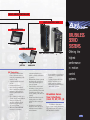
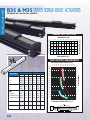
ALL NEW CONTROL SYSTEMS
•Brushless Servo
•Stepper
•Brushed DC
MECHANICAL ACTUATORS
•Screw-drives
•Belt-drives
New B3B Series!
ELECTRIC LINEAR MOTION PRODUCTS FROM
®
TOL-O-MATIC
3600-4077
CONTENTS
A COMPLETE FAMILY OF MOTION CONTROL PRODUCTS
MOTOR MOUNTING AND SYSTEM ACCESSORIES
Introduction . . . . . . . . . . . . . . . . . . . . . . . . . . . . 2
Typical Application Solutions. . . . . . . . . . . . . . . . . . . . 4
Motor Mounting Screw-Drives . . . . . . . . . . . . . . . . .
Couplers and Motor Mount Kits for In-line Mounting . .
In-line Gearhead Mounting . . . . . . . . . . . . . . . . .
In-line Motor/Gearhead Combination Mount Dimensions .
In-line Motor Mounting Dimensions . . . . . . . . . . . .
Reverse-Parallel Mounting. . . . . . . . . . . . . . . . . .
Motor Mounting Belt-Drives . . . . . . . . . . . . . . . . . .
Direct-Drive Mounting Kits, Couplers and Gearheads . . .
Direct-Drive Mounting Dimensions . . . . . . . . . . . . .
Reduction Drive Mounting . . . . . . . . . . . . . . . . .
PIT Panel Interface . . . . . . . . . . . . . . . . . . . . . .
JS Joystick Interface . . . . . . . . . . . . . . . . . . . . . .
SIT Hand-held Interface . . . . . . . . . . . . . . . . . . . .
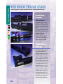
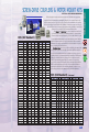
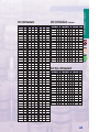
Cables. . . . . . . . . . . . . . . . . . . . . . . . . . . . . .
Switches . . . . . . . . . . . . . . . . . . . . . . . . . . . .
CONTROLLERS, DRIVES AND MOTORS
Systems Overview . . . . . . . . . . . .
Brushless Servo Systems. . . . . . .
Stepper Systems . . . . . . . . . . .
Brushed Dc Systems. . . . . . . . .
Controllers . . . . . . . . . . . . . . . .
SSC . . . . . . . . . . . . . . . . . .
MSC. . . . . . . . . . . . . . . . . .
Controller/Drive Combinations . . . . . .
MSS. . . . . . . . . . . . . . . . . .
MSCLDC. . . . . . . . . . . . . . . .
DM5C & DM6C . . . . . . . . . . .
Drives. . . . . . . . . . . . . . . . . . .
SSD. . . . . . . . . . . . . . . . . .
MSD . . . . . . . . . . . . . . . . .
DMCLDC . . . . . . . . . . . . . . .
DM5 & DM6. . . . . . . . . . . . .
Motors . . . . . . . . . . . . . . . . . .
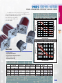
MRV Brushless Servo Motors . . . .
MRS Stepper Motors. . . . . . . . .
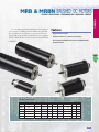
MRB & MRBN Brushed Dc Motors .
.
.
.
.
.
.
.
.
.
.
.
.
.
.
.
.
.
.
.
.
.
.
.
.
.
.
.
.
.
.
.
.
.
.
.
.
.
.
.
.
.
.
.
.
.
.
.
.
.
.
.
.
.
.
.
.
.
.
.
.
.
.
.
.
.
.
.
.
.
.
.
.
.
.
.
.
.
.
.
.
.
.
.
.
.
.
.
.
.
.
.
.
.
.
.
.
.
.
.
.
.
.
.
.
.
.
.
.
.
.
.
.
.
.
.
.
.
.
.
.
.
.
.
.
.
.
.
.
.
.
.
.
.
.
.
.
.
.
.
.
.
.
.
.
.
.
.
.
.
.
.
.
.
.
.
.
.
.
.
.
.
.
.
.
.
.
.
.
.
.
.
.
.
.
.
.
.
.
.
.
.
.
.
.
.
.
.
.
.
.
.
.
.
.
.
.
.
.
.
.
.
.
.
.
.
.
.
.
.
.
.
.
.
.
.
.
.
.
.
.
.
.
.
.
.
.
.
.
.
.
.
.
.
.
.
.
.
.
.
.
.
.
.
.
.
.
.
.
.
.
.
.
.
.
.
.
.
.
.
.
12
14
16
18
20
21
27
30
31
34
37
39
40
44
46
48
50
51
55
57
Overview . . . . . . . . . . . . . . . . . . . .
Basic Selection . . . . . . . . . . . . . . . . .
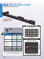
Screw-drive Actuators . . . . . . . . . . . . .
BCS/MCS Series. . . . . . . . . . . . . . .
SLS/MLS Series . . . . . . . . . . . . . . .
B3S/M3S Series. . . . . . . . . . . . . . .
Belt-drive Actuators . . . . . . . . . . . . . .
BCB Series . . . . . . . . . . . . . . . . .
B3B/M3B Series . . . . . . . . . . . . . .
Actuator Accessories . . . . . . . . . . . . . .
Dual Carrier . . . . . . . . . . . . . . . .
Dual 180˚ Carrier. . . . . . . . . . . . .
Floating Mount Bracket . . . . . . . . . .
Tube Supports . . . . . . . . . . . . . . .
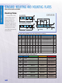
Standard Mounting and Mounting Plates.
.
.
.
.
.
.
.
.
.
.
.
.
.
.
.
.
.
.
.
.
.
.
.
.
.
.
.
.
.
.
.
.
.
.
.
.
.
.
.
.
.
.
.
.
.
.
.
.
.
.
.
.
.
.
.
.
.
.
.
.
.
.
.
.
.
.
.
.
.
.
.
.
.
.
.
.
.
.
.
.
.
.
.
.
.
.
.
.
.
.
.
.
.
.
.
.
.
.
.
.
.
.
.
.
.
.
.
.
.
.
.
.
.
.
.
.
.
.
.
.
.
.
.
.
.
.
.
.
.
.
.
.
.
.
.
.
.
.
.
.
.
.
.
.
.
.
.
.
.
.
63
65
69
74
76
78
81
84
86
88
88
90
93
94
95
MECHANICAL ACTUATORS
.
.
.
.
.
.
.
.
.
.
.
.
.
.
.
.
.
.
.
.
.
.
.
.
.
.
.
.
.
.
98
99
103
109
112
114
118
119
120
121
124
125
126
127
129
ORDERING
Actuator Requirements. . . . . . . . . . . . . . . . . . . . . . . 134
Motor and Control Requirements . . . . . . . . . . . . . . . . . 135
Field Retrofit Kits . . . . . . . . . . . . . . . . . . . . . . . . . 136
ENGINEERING RESOURCES
Glossary of Terms . . . . . . . . . . .
Conversion Tables . . . . . . . . . . .
Selecting a Motor Drive Technology. .
Basic Sizing Equations. . . . . . . . .
Sizing and Selection Limiting Factors.
Application Data Guidelines . . . . . .
Terms and Conditions of Sale. . . . .
.
.
.
.
.
.
.
.
.
.
.
.
.
.
.
.
.
.
.
.
.
.
.
.
.
.
.
.
.
.
.
.
.
.
.
.
.
.
.
.
.
.
.
.
.
.
.
.
.
.
.
.
.
.
.
.
.
.
.
.
.
.
.
.
.
.
.
.
.
.
.
.
.
.
.
.
.
.
.
.
.
.
.
.
.
.
.
.
.
.
.
.
.
.
.
.
.
.
138
140
142
143
148
150
152
©Copyright 1997, Tol-O-Matic, Inc. All rights reserved. No part of this publication may be reproduced, transmitted, transcribed, stored in a retrieval system, or translated into any language in any
form by any means without the written permission of Tol-O-Matic, Inc.
Tol-O-Matic, Axidyne, and Excellence in Motion are registered trademarks, Tol-O-Matic, Inc. Other
product and corporate names may be trademarks of other companies, and are used only for
explanation and to the owner’s benefit, without intent to infringe.
Information furnished in this catalog is believed to be accurate and reliable. However, Tol-O-Matic
assumes no responsibility for its use or for any errors that may appear in this document. Tol-OMatic reserves the right to change the design or operation of the equipment described herein and
any associated motion products without notice. Information in this document is subject to change
without notice.
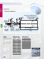
A COMPLETE
FAMILY OF
MOTION
CONTROL
PRODUCTS
1
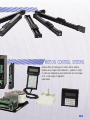
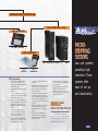
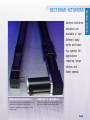
AXIDYNE MECHANICAL ACTUATORS
SYSTEM
SOLUTIONS
Five different
actuator body
types combine
with eleven
different
motion control
configurations
for the widest
variety of
application
solutions from
one source –
TOL-O-MATIC
2
The Tol-O-Matic Axidyne line of mechanical actuators offers a choice of
three load carrier support and guidance systems. Any one of the wide
variety of models available can be combined with any of the
Axidyne Motion Control Systems to create flexible, dependable and easy-to-use motion control
solutions for your application requirements.
MOTION CONTROL SYSTEMS
Axidyne offers all three types of motion control systems—
brushless servo, stepper and brushed dc—available in single
or multi-axis configurations with performance and cost ranges
to fill a wide range of application
requirements.
3
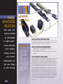
SYSTEM
TYPICAL
APPLICATION
SOLUTIONS
From lower cost,
mature brushed
dc technologies
to higher performance brushless
servo systems,
Axidyne controls
and actuator
combinations will
get your design
up and running.
4
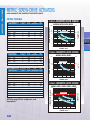
1
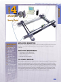
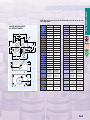
APPLICATION:
Surgical Tubing
Winder
APPLICATION DESCRIPTION:
A manufacturer of surgical tubing winds the tubing on a spool with a
constant tension as it is drawn. Constant tension is critical so as to not
stretch and decrease the opening or wall thickness.
Tol-O-Matic
Tol-O-Matic System
System
Components:
Components:
• SSC2 two axis controller
• SSD digital brushless
•
•
•
servo drive/MRV brushless servo motor
MSD microstepping
drive/MRS stepper
motor
BCS screw drive rod
bearing actuator
Motor couplings, motor
adapters and cabling
automatically selected
using the Tol-OMotion™ sizing software configuration
generator
APPLICATION REQUIREMENTS:
• Constant tension to tubing provided by winding spool
• Reciprocating tube position guide
• Tube guide and tensioning must compensate for process speed
variations
TOL-O-MATIC SOLUTION:
For precise tension control the SSD drive operating in torque mode, with
a MRV brushless servo motor provides an optimal solution. The controller must be able to provide torque adjustment that is inversely proportional to the spool diameter. This adjustment will be made each time
the tube position guide changes direction. The controller must also be
able to provide linear interpolation between the spool motor position
and the reciprocating tube guide position. A low cost solution for the
reciprocating guide is a BCS Series screw-drive actuator driven by the
MSD microstepping drive and a MRS series stepper motor. Therefore,
the controller must be able to provide an analog torque signal for the
servo drive as well as a step and direction signal for the microstepping
drive. Also, the controller must be able to supply a correction algorithm
for tension control with linear interpolation between the two axis. The
controller for this application is the SSC2 two axis/multi-function
controller.
SYSTEM
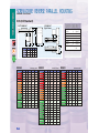
2
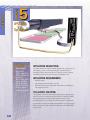
APPLICATION:
Metal Fabrication
Spot Welder
Tol-O-Matic System
Components:
• SSC2 two-axis controller
• Two MSD microstepping
•
•
•
•
•
•
drives
MRS342 stepper motor
MRS343 stepper motor
JS two-axis joystick
B3S20 screw-drive recirculating ball bearing
actuator
BCS15 screw-drive rod
bearing actuator
Motor couplings, motor
adapters, and cabling
automatically selected
using the Tol-O-Motion
sizing software configuration generator
APPLICATION DESCRIPTION:
A sheet metal fabricator needed to perform multiple spot welds on lot sizes ranging from 50 to 100
pieces. No two lots had welds in the same locations; therefore, setup simplicity was crucial..
APPLICATION REQUIREMENTS:
•
•
•
•
•
Two axis positioning system
Teach mode
Repeatability better than ± 0.005
Speed = 25 inches per second
Weld head load = 10 lbs
TOL-O-MATIC SOLUTION:
The SSC2 two axis controller with the Tol-O-Motion™ SSC user interface software provides a dedicated
joystick teach mode unlike any other for simplicity of multiple axis point-to-point programming. The flexible SSC controller is capable of providing control for any of the Tol-O-Matic drivers (brushed dc servo,
brushless servo, or steppers) but since speed and torque requirements allowed the use of a low cost
stepper system, the MSD microstepping drives with the MRS stepper motors provided the most cost
effective solution. A B3S20 (2" cylinder-style body B3S Series screw-drive) was selected for the primary
axis actuator due to the large moment load generated by the secondary axis actuator, motor and load.
For the secondary axis a BCS15 (11/2" cylinder-style body BCS Series screw-drive) actuator was selected.
5
SYSTEM
APPLICATIONS
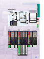
3
APPLICATION:
Furniture Gluing
Tol-O-Matic System
Components:
• SSC2 two-axis controller
• Two MSD microstepping
drives
• MRS342 stepper motor
• MRS233 stepper motor
• B3S15 screw-drive
•
•
•
6
recirculating ball bearing rodless actuator
BCS10 screw-drive
rodless actuator
BC210 pneumatic
rodless actuator
Motor couplings, motor
adapters and cabling
automatically selected
using the Tol-O-Motion
sizing and selection
software configuration
generator
APPLICATION DESCRIPTION:
A manufacturer of patio furniture needs to lay a bead of glue in various patterns as one part of a
subassembly process to be performed on a single panel as it passes through the machine.
APPLICATION REQUIREMENTS:
•
•
•
•
•
Two-axis control with circular and linear interpolation for glue head positioning
Ability to quickly and easily define glue pattern
Glue head feed
Constant move velocity/glue bead diameter
Communication to PLC
TOL-O-MATIC SOLUTION:
The SSC2 two-axis controller, using the Tol-O-Motion SSC mouse teach mode, allowed the user to
define arcs and line segments with the click of a mouse. With only moderate to low speed
requirements for positioning the gluing head, this application was solved most cost effectively
with the MDS microstepping drives and MRS stepper motors. In this application a positional
accuracy better than 0.1 was all that was required. Therefore, the BCS style actuator was first
choice. However, the moment load generated by the second axis actuator and gluing head
drove the application to a B3S15 actuator as the primary axis. Also, by choosing Tol-O-Matic, this
customer was able to save additional cost by integrating a rodless pneumatic cylinder as a constant force glue feed, in place of an additional drive, motor, and electric actuator.
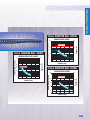
APPLICATIONS
SYSTEM
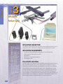
4
APPLICATION:
Scanning Device
Tol-O-Matic
Tol-O-Matic System
System
Components:
Components:
• SSC3 three-axis multi•
•
•
•
•
•
function controller
Two SSD20 digital
servo drives
Two MRV341 brushless
servo motors
SSD10 digital servo
drive
Two B3B15 belt-drive
actuators
B3S10 screw-drive
actuator
Motor couplings, motor
adapters and cabling
automatically selected
using the Tol-O-Motion
sizing and selection
software configuration
generator
APPLICATION DESCRIPTION:
The developer of a new scanning device requires a method of traversing the device 48 inches in the X axis
in less than 1 second and then indexing along the Y axis over a distance of 72 inches following each
X axis scan.
APPLICATION REQUIREMENTS:
•
•
•
•
X-Y positioning of a 50 lb. scanning head
48-inch X axis move in less than 1 second
72-inch Y travel distance
Better than 0.010-inch repeatability
TOL-O-MATIC SOLUTION:
Speed and stroke requirements in the X axis do not allow the use of a screw actuator. The moment load generated by the scanning head and 72-inch Y axis does not allow a single actuator to be used for the X-axis.
Therefore, two B3B150 belt-drive actuators were used in the gantry configuration shown. The speed requirement also do not allow the use of stepper or brushed dc systems. MRV brushless servos, driven by the SSD
drives were used in this system and controlled by a 3-axis SSC3 controller. The two X axis motors/drives
were electronically geared together while operating the third axis independently. Programming was done
over RS232 from a PC using the user friendly Tol-O-Motion™ SSC programming software.
7
SYSTEM
APPLICATIONS
5
APPLICATION:
Dye Dispenser
Tol-O-Matic
Tol-O-Matic System
System
Components:
Components:
• MSS microstepping
•
•
•
drive/controller
MRS341 stepper motor
B3S150 screw-drive rodless actuator
Motor couplings, motor
adapters and cabling
automatically selected
using the Tol-O-Motion
sizing and selection
configuration generation.
APPLICATION DESCRIPTION:
A clothing manufacturer needed to maintain constant levels of dye in a tray dispenser that they used to continuously supply dye. They had a method of
detecting the levels of die in a tray and were looking for a method to traverse
back and forth across the tray to both detect levels and dispense dye.
APPLICATION REQUIREMENTS:
• Single axis system
• Very slow speed (less than 1-inch per second
• Watch for level low detector and evaluate which of three dye dispensers to
turn on based on location.
TOL-O-MATIC SOLUTION:
This application was solved with the simplest system to set up and use, along
with the lowest cost controller/drive product offered by Tol-O-Matic. The MSS
microstepping system combines the basic single axis controller with a
microstepping drive in one package. This controller is capable of being easily
programmed to accept the level sensing input and turn on one of three outputs
based on its position. The drive is capable of driving any of Tol-O-Matic’s MRS
stepper motors.
8
APPLICATIONS
SYSTEM
6
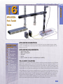
APPLICATION:
Parts Transfer
Station
APPLICATION DESCRIPTION:
Tol-O-Matic
Tol-O-Matic System
System
Components:
Components:
• MRV232 brushless servo
motor
• SSD10 digital servo
•
•
•
•
•
drive
MSC basic controller
BCB15 belt-drive
actuator
BC220 pneumatic rodless cylinder
GPP100 parallel
gripper
Motor couplings, motor
adapters and cabling
automatically selected
using the Tol-O-Motion
sizing and selection
configuration generator
A machine shop wanted to automate the removal of parts from a conveyor passing through a cleaning
solution to an assembly line conveyor. Speed was the primary consideration in this application with cost
being a close second.
APPLICATION REQUIREMENTS:
•
•
•
•
•
Two-axis linear motion
Method of grasping parts
High speed
Low cost
Input to controller from sensor to communicate part availability
TOL-O-MATIC SOLUTION:
High speed, low cost and long end-of-stroke positioning describes pneumatics. Partnering with Tol-O-Matic
assures the best system solution of both electric and pneumatic components. Therefore, the BC220 (2" bore
BC2 Series Band Cylinder) pneumatic actuator was used for the primary axis to limit the dynamic moment
load generated at the ends of stroke. Pneumatics was also used to grasp the parts by using a GPP100 parallel gripper. Since the secondary axis required stops in three different positions and a controlled deceleration
when placing parts onto the conveyor, pneumatics was not a good choice for the secondary axis. In order
to achieve the highest possible speed a belt-drive was selected instead of a screw-drive so the actuator critical screw speed was not an issue. The MRV brushless servo motor and SSD brushless servo drive were
selected for their high speed capability of up to 6000 RPM. For basic single axis servo control with I/O
available to receive a part availability signal from the proximity sensor and send commands to activate
valves for the primary axis and gripper, the MSC was a low-cost, simple to use choice.
9
SYSTEM
APPLICATIONS
7
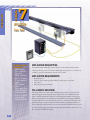
APPLICATION:
Parts Feed
Tol-O-Matic System
Components:
• MSCLDC single-axis
•
•
•
•
10
basic controller/brush
motor driver
MRB342 brush motor
with 500 line encoder
PIT panel mount user
interface
B3B20 belt-drive
actuator
Motor couplings, motor
adapters and cabling
automatically selected
using the Tol-O-Motion
sizing and selection
configuration generator.
APPLICATION DESCRIPTION:
An industrial racking manufacturer requires a method of boring numerous inline holes into
stands up to 10 feet in length. Hole locations and spacings change from lot to lot, therefore, it is
necessary to provide for quick and easy changes of hole positions.
APPLICATION REQUIREMENTS:
•
•
•
•
Single-axis system
Controller output to initiate plunge and drilling operation, input on completion
10-foot stroke
Easy-to-use operator panel interface
TOL-O-MATIC SOLUTION:
This customer was very concerned about minimizing noise, therefore more interested in dc
rather than stepper systems. Torque and speed requirements could be satisfied with either
brush or brushless systems. Since their shop was currently using a number of brush motors
and they were accustomed to brush replacement, the MRB brush motors with the MSCLDC
controller/brushed servo motor driver was the perfect low cost solution. The PIT panel mount
interface was set up to prompt the user for the first hole index, hole spacing and number of
holes, providing an operable system for even the most unexperienced users. In order to provide
the long strokes and support the moment load generated when drilling at locations up to 5 feet
from the carrier, the B3B20 was selected.
CONTROLLERS,
DRIVES AND
MOTORS
11
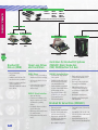
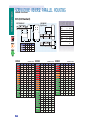
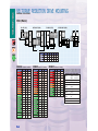
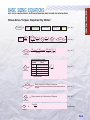
CONTROL SYSTEMS
AXIDYNE MOTION CONTROL SYSTEMS OVERVIEW
MECHANICAL ACTUATORS
AN AXIDYNE
ELECTRONIC LINEAR
MOTION CONTROL SYSTEM
IS COMPRISED OF
SEVERAL ELEMENTS:
• A mechanical actuator to convert
motor rotary motion to linear
motion.
• A motor to initiate motion.
• A drive to respond to signals from
the controller and deliver power to
move the motor.
• A controller to store and/or interpret high level commands received
from a computer or operator interface, and to generate the necessary
signals to control motor velocity,
acceleration, position, and direction
based on program and discrete
inputs.
• An operator interface to allow system operators to program or signal
the controller remotely.
This modular approach provides flexibility in control system design and
helps provide the most cost-effective
solution to a range of linear motion
control requirements.
12
(B3S, BCS, SLS, M3S, MSC, MLS,
B3B, BCB, M3B, MCB)
MOTORS
MRV (Brushless Servo)
MRS (Stepper)
MRB (Brushed DC)
DRIVES
SSD
MSD
DM5/6, DMCLDC
CONTROLLER/DRIVES
MSS
MSCLDC DM5/6C
CONTROLLERS
MSC, SSC
OPERATOR INTERFACES
PIT, JS, SIT
• The motor must provide the torque and speed necessary for the
actuator to meet the application requirements.
• The drive must convert the local power source to the power
input required by the motor.
• The motor and the drive power ratings (watts) must match the
peak and the RMS requirements of the application.
• The controller allows inputs from the operator or supervisory system (PLC or computer) to properly control the motor and achieve
the required motion profile(s).
Axidyne Motion Control Systems
Axidyne systems include brushless servos, brushed dc servos,
microsteppers, and open loop dc.
• Brushless Servo System
▲ Extremely smooth and quiet operation
CONTROL SYSTEMS
General Requirements:
Easy
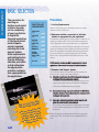
SIZING AND SELECTION SOFTWARE
Tol-O-Matic is your one source solution! Complete
electric motion solutions from Tol-O-Matic eliminate the time and hassle of mixing, matching
and integrating components. Use the
Free Tol-O-Motion Sizing & Selection
Software to select the exact
system you need.
▲ Good for high torques [up to 45 in-lbs. (5.08 N-m) continuous,
140 in-lbs. (15.82 N-m) peak]
▲ Good for high speeds, up to 6,000 RPM
▲ High resolution, 4,000 counts per revolution
▲ Provide torque control
▲ Good for short, repetitive moves
▲ Maintenance free
Easier
Or call your Tol-O-Matic distributor or the factory.
Use our expertise to help you select the best system for your application.
• Brushed DC System
▲ Low to medium cost
▲ Smooth and quiet operation
▲ Good for speeds generally less than 2500 RPM
▲ Good for torques up to 32 in-lbs. (3.62 N-m) continuous, 48 in-
lbs. (5.42 N-m) peak
▲ Good for resolutions of 1,000 counts per revolution
▲ Servo or open loop
• Microstepping System
▲ Lowest cost for precise positioning
▲ Highest resolution [up to 50,800 steps- rev] without feedback
device
▲ Good for speeds less than 2,000 RPM
▲ Good for torque requirements less than 35 in-lbs. (3.95 N-m)
▲ Smoothness better than full or half step, but not as good as
servos
▲ Good for short, repetitive moves
Easiest
MOTION CONTROL SOFTWARE
Set up is easy too. Controllers use the absolute
easiest-to-program Tol-O-Motion Motion
Control Software. Plain English commands mean no more difficult-toremember commands and
the shortest possible
startup time.
▲ Maintenance free
13
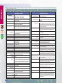
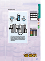
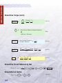
MOTORS
CONTROL SYSTEMS
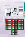
SERVO DRIVE ONLY
BASIC SINGLE AXIS
MRV231
MRV232
MRV233
MRV234
MRV341
MRV342
MRV343
SSD
MSC
Brushless Servo
Motors (MRV)
Brushless Servo
Drive (SSD)
• Rugged industrial
enclosures
• Large shafts and bearings
for longer life with high
radial axial loads
• Convenient MS connectors
to simplify motor termination and provide excellent
noise immunity
• Common industrial mechanical flanges (NEMA 23, 34)
• Integral Hall-effect devices
for commutation
• Integral temperature sensor
• Integral 1000 line TTL
encoder with differential line
driver outputs
• Ideally suited for use with
SSD drives (motor parameters are stored within drive)
• Drive MRV series brushless
servo motors
• Continuous output ratings of
0.5 kW (SSD5), 1.0
kW(SSD10), 2.0 kW (SSD20)
• Superior performance and
functionality to drives over
twice the size
• Auxiliary master encoder
input with electronic
gearing
• 8 preset positions/ speeds/
torques selected via 3 digital
input lines
• Digital autotuning for quick
and easy setup
• 4 dedicated I/O plus 5 userselectable optically isolated
digital inputs and outputs
(sourcing/active high)
14
+
SSD
Controllers for Brushless Servos
(MSC) Basic Single Axis
(SSC) Multifunction, 1-4 Axis
MSC Controller:
• Tol-O-Motion MS Motion
Control Software allows
setup & programming with
intuitive icons
• Built-in power supplies: 24
VDC, 100mA is provided for
the user for sensors and I/O
circuits.
• Differential step and direction outputs
• Accepts 110 or 220 volt AC
power
• 4 dedicated, optically isolated inputs: CW and CCW jog,
2 limits
• 4 general purpose, optically
isolated inputs
• Drive fault output
• 3 general purpose, optically
isolated outputs
• Pluggable screw terminal
connectors for I/O, motor,
AC power (all mating connectors included)
• Compact package
• Microstep resolution from
200 to 50,800 counts per
motor revolution
SERVO DRIVE/CONTROLLER
MULTI-FUNCTION / AXIS
USER INTERFACES
BRUSHLESS
SERVO
SYSTEMS
PIT PANEL CONTROL
USER INTERFACES
SSC1, SSC2, SSC3 or SSC4
JS
JOYSTICK
+
SSD
SIT
HAND-HELD
SSC Controller:
• Tol-O-Motion SSC Motion
Control Software allows
setup & programming with
intuitive icons
• Joystick and Mouse teach
modes
• Industrial enclosure
• Uses a 32-bit specialized
microcomputer and custom,
submicron gate array for
highest performance and
speed
• Up to 4 axes per unit - up to
4 units can be daisy-chained
• 8,000,000 counts/sec
encoder feedback allows
high-speed operation–2
encoders per axis
• 4M non-volatile EEPROM
memory for executing
•
•
•
•
custom application programs–permits stand-alone
operation
Multitasking feature permits
simultaneous execution of
four independent applications programs
Performs any motion task
including jogging, point-topoint positioning, linear and
circular interpolation, electronic gearing, cam and contouring
Relative and absolute positioning with more than
±2,000,000,000 counts per
move
Dedicated optoisolated
inputs for home, abort, forward and reverse limits —
noise immune
• 8 uncommitted, optoisolated
inputs and 8 programmable
outputs
• 7 analog inputs with 12-bit
ADC for interface to joysticks, sensors, pressure
transducers, potentiometers
(16-bit ADC optional)
Offering the
highest
performance
in motion
control
systems.
Brushless Servo
User Interfaces
(Host PC, SIT, PIT, JS)
Tol-O-Matic offers three
types of user friendly interfaces:
PIT panel mount, JS joystick or
SIT hand-held controller.
15
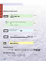
MOTORS
CONTROL SYSTEMS
MICROSTEPPING DRIVE ONLY
MRS231
MRS232
BASIC SINGLE AXIS
MRS341
MRS342
MRS343
MSD
MSS
Stepper Motors
(MRS)
Microstepping
Drive (MSD)
Controllers for Steppers
(MSS) Basic Single Axis
(SSC) Multifunction, 1-4 Axis
• Long life bearings
• High temperature insulation
• Exceptional thermal dissipation properties
• NEMA 23 and 34 mounting
• High torque to inertia ratio
•
MSS Controller/Drive:
•
•
•
•
•
16
Motor current from 0.5 to
5.5 peak amps/phase
(switch selectable, 51
settings)
Step, direction, amplifier
enable inputs, fault output,
optically isolated
16 switch selectable
microstepping resolutions:
200, 400, 1000, 2000, 5000,
10000, 12800, 18000,
20000, 21600, 25000,
25400, 25600, 36000,
50000, 508000,steps/rev
Over-temperature
protection
Idle current reduction (50%
switch selectable)
Pluggable screw terminal
connectors, mating connectors included
• Combines basic single axis
controller and drive
• Tol-O-Motion MS Motion
Control Software allows
setup & programming with
intuitive icons
• Software selectable motor
current: 0.5 to 5.5 peak
amps/phase
• Drive Voltage: 80 VDC
• Input Voltage: 110 or 220 VAC
• Microstep Resolution: 13
software selectable resolutions, 2000 to 50800
steps/revolution
• Automatic idle current reduction: 0%, 25%, 50% or 100%
software selectable
• Two dedicated, optically isolated limit switch inputs, 5 24 VDC
• CW and CCW jog inputs
• Four general purpose, filtered inputs
• Drive fault output
• 3 general purpose, optically
isolated outputs for interfacing to other equipment
STEPPER DRIVE/CONTROLLER
MULTI-FUNCTION / AXIS
USER INTERFACES
MICROSTEPPING
SYSTEMS
PIT PANEL CONTROL
USER INTERFACES
SSC1, SSC2, SSC3 or SSC4
JS
JOYSTICK
+
MSD
SIT
HAND-HELD
SSC Controller:
• Tol-O-Motion SSC Motion
Control Software allows
setup & programming with
intuitive icons
• Joystick and Mouse teach
modes
• Up to 4 axes per unit - up to
4 units can be daisy-chained
• Industrial enclosure
• Uses a 32-bit specialized
microcomputer and custom,
submicron gate array for
highest performance and
speed
• 8,000,000 counts/sec
encoder feedback allows
high-speed operation–2
encoders per axis
• 4M non-volatile EEPROM
memory for executing custom applications pro-
•
•
•
•
grams–permits stand-alone
operation
Multitasking feature permits
simultaneous execution of
four independent applications programs
Performs any motion task
including jogging, point-topoint positioning, linear and
circular interpolation, electronic gearing, cam and contouring
Relative and absolute positioning with more than
±2,000,000,000 counts per
move
Dedicated optoisolated
inputs for home, abort, forward and reverse limits —
noise immune
• 8 uncommitted, optoisolated inputs and 8 programmable outputs
• 7 analog inputs with 12-bit
ADC for interface to joysticks, sensors, pressure
transducers, potentiometers
(16-bit ADC optional)
Low cost systems
providing high
resolution. These
systems offer
ease of set up
and stabilization.
Stepper User
Interfaces
(Host PC, SIT, PIT, JS)
Tol-O-Matic offers three
types of user friendly interfaces:
PIT panel mount, JS joystick or
SIT hand-held controller.
17
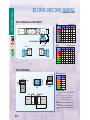
MOTORS
CONTROL SYSTEMS
MRB231
MRB231N*
MRB341
MRB341N*
MRB342
MRB342N*
MRB401
MRB401N*
MRB402
MRB402N*
* No encoder version for use with open loop configuration.
OPEN LOOP
DC DRIVE
DC DRIVE/CONTROLLER
DC DRIVE
DM5
DM6
BASIC SINGLE AXIS
DM5C
DM6C
DMCLDC
MSCLDC
Brushed DC
Motors (MRB)
Open Loop Drives
and Controllers
Controllers for Brushed DC Systems
(MSCLDC) Basic Single Axis
(SSC) Multifunction 1-4 Axis
• Rugged industrial
enclosures
• Available with 500 line TTL
encoder for servo operation
• Ideal for operation with DM
open loop drives or
DMCLDC/MSCLDC brushed
servo drives
DM5/6 Drive:
MSCLDC Controller/Drive:
• Choice of two power ratings
(matched to dc motor ratings)
• Self resetting fuse for dc supply to drive
• Lockout fault protection for
dc power supply output
under-voltage
• Combines basic single axis and
drive controller
• Tol-O-Motion MS motion control
SW allows setup and programming with intuitive icons
• Position feedback accomplished
via a two channel (A&B) differential incremental encoder
• Proportional + Derivative (PD)
feedback loop for closing the
loop around the motor.
• Enclosed configuration
DM5/6C Drive/Controller:
• Same as DM plus:
• Continuous oscillating cycle,
single complete cycle or single direction operating
modes
• Predictable first move direction for all modes
• Different profiles can be used
for each direction
• Independent dwell at end of
move
18
• Final position error of ± 3 encoder
counts. and repeatability of ± 1
encoder count
• Current trip point potentiometer
for setting torque fault limit
• Fault condition indication via 2
L.E.D.s to indicate current trip
and position error faults for field
diagnostics
• Opto-isolated external power
• Potentiometer for Damping and
Gain adjustment
Brushed Dc Servo Drive (DMCLDC)
• Line fuse protection
• Position feedback accomplished
via a two channel (A&B) differential incremental encoder
• Proportional + derivative (PD)
feedback loop for closing the
loop around the motor
• Open chassis configuration
• Final position error of ±3 encoder
counts
• Repeatability of ±1 encoder count
• Current trip point potentiometer for
setting fault limit
• Opto-isolated inputs, 5-30 Vdc
(Pulse, Direction, Reset Quad/Full)
SERVO
DRIVE/CONTROLLER
USER INTERFACES
MULTI-FUNCTION / AXIS
BRUSHED
DC
SYSTEMS
USER INTERFACES
PIT PANEL CONTROL
JS
JOYSTICK
SIT
HAND-HELD
SSC1, SSC2, SSC3 or SSC4
+
DMCLDC
SSC Controller:
• Tol-O-Motion SSC Motion
Control Software allows
setup & programming with
intuitive icons
• Joystick and Mouse teach
modes
• 8,000,000 counts/sec
encoder feedback allows
high-speed operation–2
encoders per axis
• Industrial enclosure
• Uses a 32-bit specialized
microcomputer and custom,
submicron gate array for
highest performance and
speed
• 4M non-volatile EEPROM
memory for executing custom applications programs–permits stand-alone
operation
• Up to 4 axes per unit - up to
4 units can be daisy-chained
• Multitasking feature permits
simultaneous execution of
four independent applications programs
• Performs any motion task
including jogging, point-topoint positioning, linear and
circular interpolation, electronic gearing, cam and contouring
• Relative and absolute positioning with more than
±2,000,000,000 counts per
move
• Dedicated optoisolated
inputs for home, abort, forward and reverse limits —
noise immune
• 7 analog inputs with 12-bit
ADC for interface to joysticks, sensors, pressure
transducers, potentiometers
(16-bit ADC optional)
• 8 uncommitted, optoisolated
inputs and 8 programmable
outputs
A low cost
technology to
meet basic linear
motion needs with
smooth quiet
motion.
Brushed DC User
Interfaces
(Host PC, SIT, PIT, JS)
Tol-O-Matic offers three
types of user friendly interfaces:
PIT panel mount, JS joystick or
SIT hand-held controller.
19
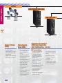
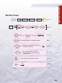
CONTROLLERS
CONTROLLERS
Axidyne controllers are available for brushless, microstepping and
brushed dc systems. Used with Tol-O-Motion motion control software these
controllers solve complex motion control problems with ease.
SSC Multi-Axis/
MultiFunction
Servo / Stepper
Controller
Axidyne’s high performance, state-of-the-art
motion controller for up
to 4 axes of servo or
stepper control
MSC Single-Axis
Servo /Stepper
Controller
This Axidyne motion
controller provides the
simplest, quickest way
to get up and running
20
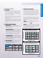
SSC1-4 SERVO/STEPPER CONTROLLER
The SSC is a high-performance, state-of-the-art
motion controller designed for stand-alone operation.
Using a 32 bit specialized microprocessor, a custom
sub micron gate array, and the Tol-O-Motion SSC
visual basic software, the controller provides DSP
performance without sacrificing ease of use and cost
effectiveness.
The SSC is available with up to 4 axes per unit
allowing the user to purchase only the number of
axes required. The SSC can also be used to control
stepper and /or servo systems.
Designed to solve complex motion problems
with superior precision, the SSC can be used for
applications requiring jogging, vector positioning of
1-4 axis, 2-D linear or circular interpolation, contouring and electronic gearing.
With the Tol-O-Motion SSC software there is no
need to learn another new programming language.
Complex motion control is made easy with the plain
English programming icons that lead you through
the entire programming process from setup to execution. Mouse and joystick teach modes allow the user
to setup coordinated motion programs by moving to
and clicking on desired locations.
Features:
• High performance motion control
packaged in an industrial enclosure
• Uses a 32-bit specialized microcomputer and custom, submicron
gate array for highest performance
and speed
• Up to 4 axes per unit - up to 4 units
can be daisy-chained
• 125 µsec per axis servo update rate
for high bandwidth
• Controls servo motors and/or step
motors
• Sophisticated PID filter with velocity
and acceleration feed forward for
optimum precision
• 16 bit DAC for fine resolution control
• 8,000,000 counts/sec encoder feedback allows high-speed operation–2
encoders per axis
• 4M EEPROM memory for executing
custom applications programs–permits stand-alone operation
• Multitasking feature permits simultaneous execution of four independent applications programs
• Programmable acceleration and
deceleration with profile smoothing
to eliminate jerk
• 7 analog inputs with 12-bit ADC for
interface to joysticks, sensors, pressure transducers, potentiometers
(16-bit ADC optional)
• Position feedback for each axis can
be from analog signal or encoder
• Continuous vector feed of infinite
number of linear and arc segments
for smooth motion
• Auxiliary encoder inputs and dualloop damping — ideal for backlash
compensation
• Contour mode for profiling along
computer generated paths such as
parabolic or spherical profiles
• Programmable event triggers for
monitoring elapsed time, position,
speed, and motion complete
• Selectable linear scale simplifies
linear motion programming
• I/O functions, timers, and logic
functions for executing PLC tasks
• Performs any motion task including
jogging, point-to-point positioning,
linear and circular interpolation, electronic gearing, cam and contouring
• 254 symbolic variables and 8000
element array space for data storage
• Relative and absolute positioning
with more than ±2,000,000,000
counts per move
• Dedicated optoisolated inputs for
home, abort, forward and reverse
limits — noise immune
• Compact size: 13" high x 2.5" wide x
6.6" deep
• Internal, universal switching power
supply for direct connection to AC
outlet (110V or 220V)
• IDC connectors on front panel connect to DIN rail mounted screw terminal breakouts included
• 8 uncommitted, optoisolated inputs
and 8 programmable outputs
21
CONTROLLERS
FEATURES • SPECIFICATIONS • PROGRAMMING • DIMENSIONS • CONNECTORS • ORDERING
CONTROLLERS
SPECIFICATIONS
SPECIFICATIONS
Performance
Servo Loop Cycle Time:
Block Execution Time:
Position Accuracy:
Velocity Accuracy:
Synchronization:
Position Capture Accuracy:
Parameter Ranges
Position Range:
Velocity Range:
Acceleration/deceleration:
Error Limit:
Gear Ratio:
Filter Constants:
Motor Command Resolution:
Step Motor Control Mode:
Step Pulse Frequency:
Number of Variables:
Array Size:
Memory Size:
Mechanical
Dimensions:
Weight:
Inputs/Outputs
Feedback:
General Purpose Inputs:
General Purpose Outputs:
General Purpose
Analog Inputs:
Dedicated Inputs per Axis:
Dedicated Outputs per Axis:
SSC Multi-Axis/Multi-Function
Servo/Stepper Controller
SSC 1: 250 µsec; SSC 2: 375 µsec
SSC 3: 500 µsec; SSC 4: 500 µsec
In contour mode, up to 1000 blocks (moves)/sec with full trajectory calculation
±1 quadrature count
Long-term: phase-locked, better than .003%
Short-term: system dependent
All axes in the same unit are perfectly synchronized and
share the same servo cycle. All cards sharing synchronization are perfectly synchronized in the same servo cycle.
25 µsec with optoisolation; 1 µsec if by-pass optoisolation.
±2,147,483,647 counts/move; automatic rollover; no limit in
jog or vector modes.
Up to 8,000,000 counts/sec
1,024 to 67,107,840 c/sec2
±32,767 counts
±127.9999
Kp: 0 to 1023.875
Kd: 0 to 4095.875
Ki: 0 to 2047.875
16 bits or .0003 V
Full, half or microstep
2,000,000 pulse/sec
254
8000 elements in up to 30 arrays
1000 lines x 80 characters
13" high x 2.5" wide x 6.6" deep
6 lbs.
Two channels of A/B quadrature per axis with third channel
for index. In servo mode, includes auxiliary encoder inputs for
each axis. Single ended or differential. Can be configured for
quadrature, pulse and direction, or from analog inputs.
8 optoisolated inputs
8 TTL outputs
7, ±10 V; 12-bit resolution (16-bit optional)
Forward and reverse limits, high-speed position latch, home.
Analog motor command, pulse and direction, amplifier
enable, encoder output compare.
Available Power to Drive External Devices
+5 V
1.5 Amp
+12 V
750 mA
-12 V
200 mA
22
SPECIFICATIONS
SSC Multi-Axis/Multi-Function
Servo/Stepper Controller
Environment
Operating Temperature:
32° to 158° F (0° to 70° C)
Communication Interface
Selectable Baud Rate:
300, 1200, 4800, 9600, 19200, 38400. Handshake mode
available.
I/O Description (Inputs)
Encoder, A+, B+:
Position feedback from incremental encoder with two channels in quadrature.The encoder can be analog (±12V) or TTL.
Note: Encoder that produce outputs in th format of pluses and
direction can also be used.
Encoder Index I+:
Once-per-revolution encoder pulse; used in Homing sequence
or Find Index command. Minimum index pulse width is 120
nsec.
Encoder, A-, B-, I-:
Optional differential inputs from encoder; used for enhanced
noise immunity.
Auxiliary Encoder:
Inputs for additional encoder; used when encoders on both
the motor and the load are required.
Abort*#:
Stops commanded motion instantly and also aborts application program.
Reset*#:
System reset.
Forward and Reverse
When active, inhibits motion in forward or
Limit Switch #:
reverse direction and also causes the limit
switch subroutine #LIMSWI to execute.
Home Switch #:
Input for Homing (HM) and Find Edge (FE) instructions.
Input 1 - Input 8#:
Uncommitted inputs; can be defined by the user to trigger
events or interrupt program.
Latch#:
High-speed position latch to capture axis position within 25
µsec (bypass optoisolation for .1 µsec capture). AL command
arms latch. Input 1, 2, 3, 4 latches X, Y, Z, W respectively.
Analog 1 - Analog 7:
Analog inputs that can be connected to external analog signals such as force or pressure transducers. Can also be used
for position feedback. 12-bit resolution ADC for ±10 V input.
I/O Description (Outputs)
Analog Motor Command:
±10 V range signal for driving servo amplifiers; 16-bit resolution or .0003 V, 3 mA.
Amp enable*:
Signal to disable and enable an amplifier. Amp enable goes
low when a motor-off condition occurs. For step motors, this
pin provides for reduced current when low.
Step Out:
Pulses for input to a step motor driver.The pulses can be
either active low or high. Upon Reset, the output will be low if
the SM jumper is on, Tristate if off.The STEP OUT pin also
provides the PWM signal for servo motors.
Direction:
Used with the STEP OUT signal to give direction to step
motors or servo motors in the sign magnitude mode.
Error*:
The signal goes low when the position error on any axis
exceeds the limit specified by the error command, ER.
Output 1 - Output 8:
These 8 TTL outputs are uncommitted and can be designated by the user to toggle relays and trigger external events.
The output lines are toggled by Set Bit (SB), Clear Bit (CB),
Define Bit (OB), and OP instructions. Upon reset these signals will be low.
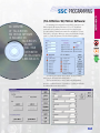
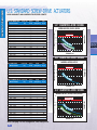
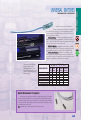
SSC PROGRAMMING
CONTROLLERS
(Tol-O-Motion SS) Motion Software:
AN OVERVIEW
OF TOL-O-MOTION
SSC MOTION SOFTWARE
IS INCLUDED ON
TOL-O-MATIC’S
CD-ROM.
CALL YOUR
DISTRIBUTOR
OR TOL-O-MATIC
1-800-328-2174
Programming is accomplished through RS232 connection to an
IBM compatible PC running Windows 3.1, 95 or NT. Visual Basic
panels start out by guiding the user through the complete setup
process including communications and axis configuration. The user
then is able to enter into different program options including Display
panel, Jog, Teach, Programmer, Tune and Data Acquisition.
The Display panel (shown above) allows the user to identify
axis locations and status faults, limits, and I/O.
The Jog panels allow the user to easily setup independent
motion or coordinated motion. The panels for Jog Setup and Circular
Coordinated Motion are shown below.
23
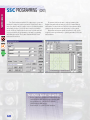
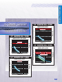
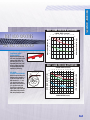
SSC PROGRAMMING
(CONT.)
CONTROLLERS
Two Teach modes are available. The easiest way to get up and
running is by using the joystick teach mode. This allows the user to
write a program by using a joystick to move to the desired positions
and pressing a button to record. For more complex coordinated
moves, the Mouse Teach mode allows the user to define arcs and
vectors on a scaled plot representation of the axis by positioning
and clicking the mouse. The Joystick Teach and Mouse Teach
modes are shown below.
Program mode allows the user to write programs in plain
English commands, without having to pull out command listings
and formats. The user clicks on a button for a given function and is
guided through the function with various easy to follow panels.
Diagnostics and autotune panels are included to help get the
complete system up and running to optimal performance, with ease
and confidence.
Tol-O-Matic System Compatibility
•
•
24
Used to control any combination of brushless servo systems (SSD drives/MRV motors), stepper systems (MSD
drives/MRS motors), or Brushed servo systems
(DMCLDC drives/MRB motors)
Hand held (SIT) or joystick (JS) user interfaces
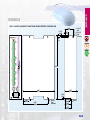
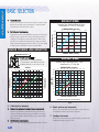
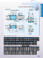
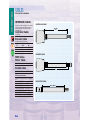
SSC 1-4 MULTI-AXIS/MULTI-FUNCTION SERVO/STEPPER CONTROLLER
0.175"
(4.45)
R 0.18"
(4.6)
0.35"
(8.9)
ERROR
J3
1
J5
13.00"
J4
X Y Z W
OFFSET
1
AMP
1
GENERAL I / 0
AUX ENCODER
1
J2
RESET
MAIN
R 0.10"
(2.5)
2 Places
Stepper/Servo
Controller
POWER
1.80"
(45.7)
0.70"
(17.8)
AUX SERIAL
MAIN SERIAL
MRST
1200
9600
19.2K
HSHK
2.50"
(63.5)
6.60"
(167.6)
0.20"
(5.1)
TOL-O-MATIC
Hamel, MN
1.40"
(35.6)
5.20"
(132.1)
R 0.12"
(3.0)
4 Places
1.15"
(29.2)
1.25"
(31.8)
1.35"
(34.3)
R 0.10"
25
CONTROLLERS
DIMENSIONS
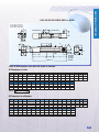
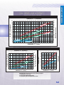
SSC ORDERING INFORMATION AND CONNECTORS
CONTROLLERS
Connectors
SSC J2 MAIN; 60-PIN IDC;
1 Ground
2 5V
3 Error
4 Reset
5 Switch Common
6 Forward Limit - X
7 Reverse Limit - X
8 Home - X
9 Forward Limit - Y
10 Reverse Limit - Y
11 Home - Y
12 Forward Limit - Z
13 Reverse Limit - Z
14 Home - Z
15 Forward Limit - W 16 Reverse Limit - W
17 Home - W
18 Output 1
19 Input Common
20 Latch X or Input 1
21 Latch Y or Input 2 22 Latch Z or Input 3
23 Latch W or Input 4 24 Abort Input
25 Motor Command X 26 Amp Enable X
27 Motor Command Y 28 Amp Enable Y
29 Motor Command Z 30 Amp Enable Z
31 Motor Command W 32 Amp Enable W
33 A+ X
34 A- X
35 B+ X
36 B- X
37 I+ X
38 I- X
39 A+ Y
40 A- Y
41 B+ Y
42 B- Y
43 I+ Y
44 I- Y
45 A+ Z
46 A- Z
47 B+ Z
48 B- Z
49 I+ Z
50 I- Z
51 A+ W
52 A- W
53 B+ W
54 B- W
55 I+ W
56 I- W
57 +12 V
58 -12 V
59 5 V
60 Ground
SSC J5 GENERAL I/O; 26-PIN IDC;
1 Analog 1
2 Analog 2
3 Analog 3
4 Analog 4
5 Analog 5
6 Analog 6
7 Analog 7
8 Ground
9 5V
10 Output 1
11 Output 2
12 Output 3
13 Output 4
14 Output 5
15 Output 6
16 Output 7
17 Output 8
18 Input 8
19 Input 7
20 Input 6
21 Input 5
22 Input 4 (Latch W)
23 Input 3 (Latch W)
24 Input 2 (Latch W)
25 Input 1 (Latch W)
26 Input Common
(Isolated 5 V)
26
SSC J3 AUXILIARY ENCODER;
20-PIN IDC;
1 Sample Clock
2 Reserved
3 B- Aux W
4 B+ Aux W
5 A- Aux W
6 A+ Aux W
7 B- Aux Z
8 B+ Aux Z
9 A- Aux Z
10 A+ Aux Z
11 B- Aux Y
12 B+ Aux Y
13 A- Aux Y
14 A+ Aux Y
15 B- Aux X
16 B+ Aux X
17 A- Aux X
18 A+ Aux X
19 5 V
20 Ground
SSC J4 DRIVER; 20-PIN IDC;
1 Motor Command X 2 Amp Enable X
3 PWM X/Step X
4 Sign X/Dir X
5
6 Motor
Command Y
7 Amp Enable Y
8 PWM Y/Step Y
9 Sign Y/Dir Y
10
11 Motor Command Z 12 Amp Enable Z
13 PWM Z/Step Z
14 Sign Z/Dir Z
15 5 V
16 Motor
Command W
17 Amp Enable W
18 PWM W/Step
W
19 Sign W/Dir W
20 Ground
AC POWER INPUTS; 4-PIN
DETACHABLE SCREW TYPE:
Hot Connects to 110 or 220 AC
NC
No Connect
Neutral Return for AC
Earth
Chassis input
RS232 - MAIN PORT; 9-PIN:
1 CTS - output
2 Transmit data output
3 Receive data - output 4 RTS - input
5 Ground
6 CTS - output
7 RTS - input
8 CTS - output
9 5V
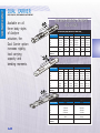
Configuration
Code
Includes
See below • 7ft. (2m) RS232 Cable
• 60 pin/18" (457mm) ribbon cable & 60 pin breakout*
• 26 pin/18" (457mm) ribbon cable & 26 pin breakout*
• If any axis configured w/ step & direction output
- 20 pin/18" (457mm) ribbon cable & 20 pin breakout**
• User Manual
• Tol-O-Motion SSC Software
SSC _ _
(MULTI-AXIS/MULTI-FUNCTION SERVO STEPPER CONTROLLER)
Configuration
Code
Axis X**
SSC 10
SSC 21
SSC 22
SSC 31
SSC 32
SSC 33
SSC 34
SSC 41
SSC 42
SSC 43
SSC 44
SSC 45
SSC 46
SSC 47
SSC 48
Axis Y
Axis Z
Axis W
Tol-O-Matic
Part #
per Drive
per Drive
ST
per Drive
SV
per Drive
ST
ST
per Drive
ST
SV
per Drive
SV
ST
per Drive
SV
SV
per Drive
ST
ST
ST
per Drive
ST
ST
SV
per Drive
ST
SV
ST
per Drive
ST
SV
SV
per Drive
SV
ST
ST
per Drive
SV
ST
SV
per Drive
SV
SV
ST
per Drive
SV
SV
SV
ST = STEP AND DIRECTION OUTPUT SV = ± 10 V OUTPUT
3600-0044
3600-0045
3600-0046
3600-0047
Systems will be preconfigured at factory by using the appropriate
5th digit in configurator. The unit may be changed by the user at a
later time by the insertion or removal of jumper.
* To avoid shipping with DIN rail mount break out terminals, add BON to configurator
** X axis is configured according to drive ordered
•If DMCLDC or MSD configured for step and direction output
•If SSD configured for ±10 V output
CABLES
RS232 - AUXILIARY PORT; 9-PIN:
1 CTS - input
2 Transmit data input
3 Receive data - output 4 RTS - output
5 Ground
6 CTS - input
7 RTS - output
8 CTS - input
9 5V
Description
20 pin breakout
26 pin breakout
60 pin breakout
20 pin ribbon cable
Tol-O-Matic
Part No.
3600-1340
3600-1341
3600-1342
3600-1345
Description
26 pin ribbon cable
60 pin ribbon cable
RS232 Cable
Tol-O-Matic
Part No.
3600-1346
3600-1347
3600-1172
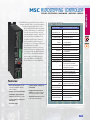
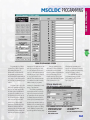
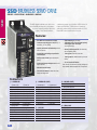
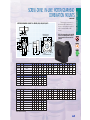
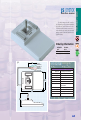
MSC MICROSTEPPING CONTROLLER
The MSC Microstepping Controller provides the
simplest, quickest way to get up and running
in a single axis application. The Tol-OMotion MSC software allows sophisticated programming to be achieved by
even the most novice user, through
icons arranged in a simple, easy to follow format. Once programmed over
the RS232 the PC may be removed
and program interaction achieved
through I/O, or by using the PIT panel
mount interface. The MSC
Microstepping controller comes as a
stand alone controller making it ideal
for operation with the SSD brushless
servo drive, or in a similar configuration integral to the MSD microstepping drive (MSS) or the DMCLDC
brushed DC motor driver (MSCLDC).
SPECIFICATIONS
SPECIFICATIONS
Power
Input Voltages (AC line):
Input Current (AC line):
Input Fuses
(AC line, L1 & L2/N):
Parameter Ranges
Distance:
Speed:
Acceleration:
Deceleration:
Time Delays:
Output Pulse Widths:
Iterations per loop:
Microstep Resolution:
Outputs
5V:
24V:
Features:
• Built-in power supplies: 24 VDC,
100mA is provided for sensors
and I/O circuits.
• Accepts 110 or 220 volt AC power
• 4 dedicated, optically isolated
inputs: CW and CCW jog, 2 limits
• 4 general purpose, optically isolated inputs
• 3 general purpose, optically isolated outputs
• Pluggable screw terminal connectors for I/O, motor, AC power
(all mating connectors included)
• Selectable linear scale simplifies
linear motion programming
STEP & Dir (logic high):
STEP & Dir (logic low):
STEP output frequency:
STEP output duty cycle:
I/O
Inputs:
Input impedance - IN 1-4,
CW Jog, CCW Jog, limits:
Outputs:
output current (Out 1-3):
output voltage (Out 1-3):
Environment
Ambient Temp. Range:
MSC Microstepping Controller
110 or 220 Vac, 50-60Hz (switch selected)
0.2A max. at 110 Vac
0.25A fast acting TR5 style
1 to 16,000,000 steps
.025 to 50 revolutions per second (in any
microstep resolution)
1 to 3000 rev/sec/sec
1 to 3000 rev/sec/sec (set independently
from acceleration)
0.1 to 25.5 seconds
2 to 500 milliseconds
1 to 255
200-50800 steps/rev
50 mA used by PIT (if connected)
±5%, 100 mA max, self resetting fuse,Not
isolated from internal circuitry
±5%, 100 mA max, self resetting fuse,
Not isolated from internal circuitry
2.5V min, 3.4V typ, with 20mA load
0.5V max, 0.3V typ, with 20mA load
50 Hz to 2.54 MHz
50%
bidirectional, optically isolated, 5-24 Vdc
2200 Ohms
optically isolated, sourcing or sinking
100mA max
24Vdc max
32° to 122° F (0 to 50° C)
• Drive fault output
27
CONTROLLERS
FEATURES • SPECIFICATIONS • PROGRAMMING • DIMENSIONS • ORDERING
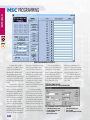
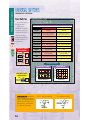
MSC PROGRAMMING
CONTROLLERS
MAIN PROGRAMMING SCREEN
Programmable by RS232
connection to an IBM compatible PC running Windows 3.1,
Windows 95 or Windows NT.
Programming software and
cable included. Programming is
very easy to learn and requires
no previous programming experience.
Programs can be up to 100
lines long. Instructions are powerful, so 100 lines can provide
the user with a sophisticated
program. For example, in one
program line the motor can be
moved until a sensor changes
state, then fed a precise distance to stop, delayed and
returned to the starting point.
Distances, delays, feed and
return speeds, acceleration and
deceleration parameters are all
included in the single program
28
instruction. The same move can
take 10 program lines or more
on other indexers. There are a
total of 13 different instructions,
including input/output, branches, loops and motion commands. These instructions can
be combined to make a nearly
infinite variety of programs,
meeting the demands of a wide
range of applications.
The main programming
screen is shown above. On the
right of the screen are the 100
program lines. In the center are
command buttons and on the
left are global parameters such
as microstep resolution and jog.
Clicking on a program step icon
brings up a sequence of dialog
boxes, making program selection and parameter setting easy.
Once programmed, the
cable can be removed and the
indexer-drive will run stand
alone. Programs and parameters
are stored internally in nonvolatile memory. Upon power
up, the drive automatically senses the connection to the
Windows programming software. If no connection is detected, the program is automatically
executed starting on line 1.
The MSC also allows program interaction to take place
using the PIT user interface
(page 124).
TYPICAL DIALOG BOX
(FOR SETTING FEED TO LENGTH INSTRUCTIONS
THE COMMAND BUTTON FEATURES INCLUDE:
•
•
•
•
DOWNLOAD PROGRAM TO DRIVE
UPLOAD PROGRAM FROM DRIVE
EXECUTE PROGRAM
SAVE PROGRAM TO DISK
• LOAD PROGRAM FROM DISK
• PRINT PROGRAM
• QUIT THE PROGRAMMING SOFTWARE
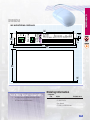
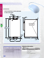
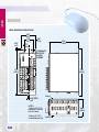
CONTROLLERS
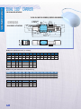
DIMENSIONS
MSC MICROSTEPPING CONTROLLER
7.17"
(182.1)
+24 VDC
24V GND
+5 VDC
GND
STEP+
STEP–
DIR+
DIR–
OUT1+
OUT1–
OUT2+
OUT2–
OUT3+
OUT3–
IN/JOG COM
IN1
IN2
IN3
IN4
CWJOG/IN5
CCWJOG/IN6
LIMIT COM
CW LIMIT
CCW LIMIT
STOP
MicroStepping
Motor Controller
MSC
TOL-O-MATIC
PC/MMI
Hamel, MN
AC POWER
G
L2/N
L1
1.250"
(31.8)
0.625"
(15.9)
0.20"
(5.1)
PWR
7.625"
(193.7) 8.000"
(203.2)
3.86"
(98.0)
0.06"
(1.5)
Ordering Information
Tol-O-Matic System Compatibility
•
•
Provides control for SSD Brushless Servo Drive
PIT (Panel Mount User Interface)
Configuration
Code
MSC
Includes
• Microstepping Controller
• 7ft. RS232 Cable
• User Manual
• Tol-O-Motion MSC Software
Tol-O-Matic Part #
3600-0040
29
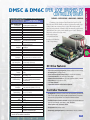
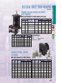
CONTROLLER/DRIVES
CONTROLLER/DRIVE COMBINATIONS
Axidyne controller/drive combinations are available for microstepper and
brushed dc systems. These controller/drives combine flexibility and superior
performance in compact packages
MSCLDC Brushed DC
Servo
Controller/Driver
For use with Axidyne MRB
motors, for applications that
require a servo system, without
the expense of brushless motors.
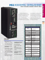
MSS Microstepping
Controller/Driver
For use with Axidyne MRS
motors, this stand alone unit is
the simplest and most cost effective way to provide single axis
motion to Tol-O-Matic’s stepper
motor/ actuator systems.
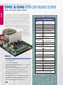
DM5/6C Open Loop
Brushed DC
Controller/ Drive
Module
30
For use with Axidyne MRB
motors, this low cost
controller/drive module is
intended for systems that do not
require position feedback.
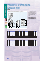
FEATURES • SPECIFICATIONS • PROGRAMMING • DIMENSIONS • ORDERING
Tol-O-Matic’s MSS stand alone
microstepping controller/drive system is
absolutely the simplest and most costeffective way to provide single axis
motion to Tol-O-Matic’s stepper
motor/actuator systems. The Tol-OMotion MSS software allows sophisticat-
ed programming to be achieved by even
the most novice user, through icons
arranged in a simple, easy to follow format. Once programmed over the RS232
the PC may be removed and program
interaction achieved through I/O or the
PIT (Panel Mount Interface).
SPECIFICATIONS
SPECIFICATIONS
Power
Input Current (AC line):
Input Voltages (AC line):
Input Fuses
(AC line):
Motor Current Output:
Internal Bus Voltage:
Parameter Ranges
Distance:
Speed:
Features:
• Motor Current: 0.5 to 5.5
amps/phase, (software selectable)
Acceleration:
Deceleration:
• Two dedicated, optically isolated
limit switch inputs, 5 - 24 VDC
• Drive Voltage: 80 VDC (from internal linear, toroidal power supply)
• CW and CCW jog inputs
• Input Voltage: 110 or 220 VAC
(switch selectable)
• Four general purpose, filtered
inputs
• Microstep Resolution: 13 resolutions, 2000 to 50800 steps/revolution (software selectable)
• Drive fault output (activated by
overcurrent or over-temperature
condition)
• Automatic idle current reduction:
0%, 25%, 50% or 100% (software
selectable)
• 3 general purpose, optically isolated outputs for interfacing to
other equipment
• Connectors: pluggable, screw terminal connectors are included.
• Uses Tol-O-Motion MSS Software
Time Delays:
Microstep Resolution:
Inputs
Input Current - Input 1-4,
CW Jog, CCW Jog:
Input Current - CW Limit,
CCW Limit:
Outputs
Outputs 1-3:
5V Output:
Environment
Maximum Case Temp.:
Ambient Temp. Range:
MSS Microstepping Controller/Driver
Varies with motor & load
6.0A max. at 110 Vac
110 or 220 Vac, 50-60Hz (switch selected)
6.3A time lag, TR5 style
0.5 - 5.5 A / phase peak
80 Vdc (unregulated)
1 to 16,000,000 steps
.025 to 50 revolutions per second (in any
microstep resolution)
1 to 3000 rev/sec/sec
1 to 3000 rev/sec/sec (set independently
from acceleration)
0.1 to 25.5 seconds
2000-50800 steps/rev
5 mA (internally pulled up to 5 Vdc)
5 - 15 mA
(internally limiting resistor for 5v logic)
Optically isolated, 24 Vdc max, 100mA
±5%, 100mA max, self resetting fuse
50 mA used by PIT (if connected)
167° F (75° C)
32° to 113° F (0 to 45° C)
31
CONTROLLER/DRIVES
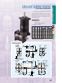
MSS MICROSTEPPING CONTROLLER/DRIVER
CONTROLLER/DRIVES
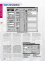
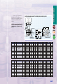
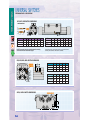
MSS PROGRAMMING
MAIN PROGRAMMING SCREEN
Programmable by RS232
connection to IBM compatible
PC running Windows 3.1,
Windows 95 or Windows NT.
Programming software and
cable included. Programming is
very easy to learn and requires
no previous programming experience.
Programs can be up to 100
lines long. Instructions are powerful, so 100 lines can provide
the user with a sophisticated
program. For example, in one
program line the motor can be
moved until a sensor changes
state, then fed a precise distance to stop, delayed and
returned to the starting point.
Distances, delays, feed and
return speeds, acceleration and
deceleration parameters are all
included in the single program
32
instruction. The same move can
take 10 program lines or more
on other indexers. There are a
total of 13 different instructions,
including input/output, branches, loops and motion commands. These instructions can
be combined to make a nearly
infinite variety of programs,
meeting the demands of a wide
range of applications.
The main programming
screen is shown above. On the
right of the screen are the 100
program lines. In the center are
command buttons and on the
left are global parameters such
as microstep resolution and jog.
Clicking on a program step icon
brings up a sequence of dialog
boxes, making program selection and parameter setting easy.
Once programmed, the
cable can be removed and the
indexer-drive will run stand
alone. Programs and parameters
are stored internally in nonvolatile memory. Upon power
up, the drive automatically senses the connection to the
Windows programming software. If no connection is detected, the program is automatically
executed starting on line 1.
The MSS also allows program interaction to take place
using the PIT user interface
(page 124).
TYPICAL DIALOG BOX
(FOR SETTING FEED TO LENGTH INSTRUCTIONS
THE COMMAND BUTTON FEATURES INCLUDE:
•
•
•
•
DOWNLOAD PROGRAM TO DRIVE
UPLOAD PROGRAM FROM DRIVE
EXECUTE PROGRAM
SAVE PROGRAM TO DISK
• LOAD PROGRAM FROM DISK
• PRINT PROGRAM
• QUIT THE PROGRAMMING SOFTWARE
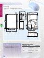
CONTROLLER/DRIVES
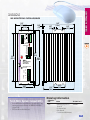
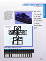
DIMENSIONS
MSS MICROSTEPPING CONTROLLER/DRIVER
3.00"
(76.2) 1.25"
(31.8)
0.06"
(1.5)
0.25"
(6.3)
5.45"
(138.4)
2.02"
(51.3)
LIMITS
CW+
CWIN 1
CCW+
IN 2
CCWIN 3
GND
IN 4
GND
JOG CW
+5V
JOG CCW
+5V
GND
GND
POWER
OVER TEMP
OVER CURRENT
OUT 1+
OUT 1OUT 2+
OUT 2OUT 3+
OUT 3FAULT+
FAULT-
RS232
STOP
8.00"
(203.2)
MSS
8.97"
(227.8)
9.25"
(234.9)
MicroStepping
Controller /
Motor Drive
AC POWER
MOTOR
TOL-O-MATIC, INC.
Hamel, MN
B–
B+
A–
A+
GND
N
L
3.07"
(78.0)
5.30"
(134.6)
2.15"
(54.6)
Ordering Information
Tol-O-Matic System Compatibility
Configuration
Code
•
MSS
•
Drives MRS series stepper motors to provide motor./drive
system performance shown in the MRS motor section
(pages 55-56)
PIT (Panel Mount User Interface)
Includes
Tol-O-Matic Part #
• Microstepping Drive &
3600-9603
Controller
• 7ft. RS232 Cable
• User Manual
• Tol-O-Motion MSS Software
33
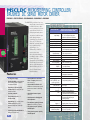
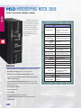
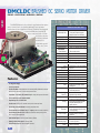
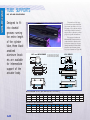
MSCLDC MICROSTEPPING CONTROLLER/
BRUSHED DC SERVO MOTOR DRIVER
FEATURES • SPECIFICATIONS • PROGRAMMING • DIMENSIONS • ORDERING
The MSCLDC provides a low cost
single axis controller and
brushed dc servo drive
in one package, for those
applications that do not
justify significantly more
expensive brushless systems. Setup and programming is performed
with the Tol-O-Motion
MSCLDC software, allowing sophisticated programming to be
achieved by even the
most novice user,
through icons arranged
in a simple easy to follow
format. Once programmed over the RS232,
the PC may be removed
and program interaction
achieved through I/O or
the PIT (Panel Mount
User Interface).
Features:
• 10 Amp power supply
• Position feedback accomplished via
a two channel (A&B) differential
incremental encoder
• Proportional + Derivative (PD)
feedback loop for closing the loop
around the motor
• Line fuse protection
• Final position error of +/- 3
encoder counts
• Repeatability of ± 1 encoder count
• Position error L.E.D. (± 127
encoder counts) and current trip
faults
• Current trip point potentiometer for
setting torque fault limit
34
• Fault conditions via solid state
Form “C” output (position error
and current trip)
• Fault condition indication via 2
L.E.D.s to indicate current trip and
position error faults for field diagnostics
• Opto-isolated external power
(Vdc I/O).
• Potentiometer for Damping and
Gain adjustment
• Four dedicated, optically isolated
inputs: CW & CCW jog, 2 limits
• Four general purpose, optically
isolated inputs
• Three general purpose, optically
isolated outputs
SPECIFICATIONS
SPECIFICATIONS
Power
Input Voltages:
Input Frequency:
Input Current:
Output Voltage (DC line):
Output Continuous Current:
Output Peak Current:
Performance
System Resolution:
Repeatability:
Final Position Accuracy:
P.W.M. Frequency:
Over Current Rating:
Parameter Ranges
Distance:
Speed:
Acceleration:
Deceleration:
Time Delays:
Inputs
INPUT CURRENT - Input
1-4, CW Jog CCW Jog:
INPUT CURRENT - CW
Limit, CCW Limit:
Potentiometer Inputs
Current Trip:
Gain:
Damping:
Outputs
Outputs 1-3
5V Output
Environment
Ambient Temp. Range:
MSCLDC Microstepping Controller/
brushed DC Servo Motor Driver
85 - 132 Vac (European input power
available on request as a modification)
60 Hz
7 Amp (max.)
48 Vdc (no-load condition)
10 Amp
15 Amp
(1 second operating at peak condition)
1000 counts per revolution
± 1 encoder count
± 3 encoder counts
20 KHz
125% of continuous rating
1 to 16,000,000 steps
.025 to 50 rev/sec
1 to 3000 rev/sec/sec
1 to 3000 rev/sec/sec
(independent of acceleration)
0.1 to 25.5 seconds
5 mA (internally pulled up to 5 Vdc)
5 - 15 mA (internal limiting resistor
for 5 V logic)
Adjustment of Torque Fault Limit
Position error adjustment between
commanded and actual feedback signals
System setting time adjustment between
the system natural frequency and
operating frequency
Optically isolated, 24 Vdc max., 100 mA
±5%, 100 mA max, self resetting fuse
32° to 113° F (0 to 45° C)
MAIN PROGRAMMING SCREEN
Programmable by RS232
connection to IBM compatible
PC running Windows 3.1,
Windows 95 or Windows NT.
Programming software and
cable included. Programming is
very easy to learn and requires
no previous programming experience.
Programs can be up to 100
lines long. Instructions are powerful, so 100 lines can provide
the user with a sophisticated
program. For example, in one
program line the motor can be
moved until a sensor changes
state, then fed a precise distance to stop, delayed and
returned to the starting point.
Distances, delays, feed and
return speeds, acceleration and
deceleration parameters are all
included in the single program
instruction. The same move can
take 10 program lines or more
on other indexers. There are a
total of 13 different instructions,
including input/output, branches, loops and motion commands. These instructions can
be combined to make a nearly
infinite variety of programs,
meeting the demands of a wide
range of applications.
The main programming
screen is shown above. On the
right of the screen are the 100
program lines. In the center are
command buttons and on the
left are global parameters such
as microstep resolution and jog.
Clicking on a program step icon
brings up a sequence of dialog
boxes, making program selection and parameter setting easy.
Once programmed, the
cable can be removed and the
indexer-drive will run stand
alone. Programs and parameters
are stored internally in nonvolatile memory. Upon power
up, the drive automatically senses the connection to the
Windows programming software. If no connection is detected, the program is automatically
executed starting on line 1.
The MSCLDC also allows
program interaction to take
place using the PIT user interface (page 124)
TYPICAL DIALOG BOX
(FOR SETTING FEED TO LENGTH INSTRUCTIONS
THE COMMAND BUTTON FEATURES INCLUDE:
•
•
•
•
DOWNLOAD PROGRAM TO DRIVE
UPLOAD PROGRAM FROM DRIVE
EXECUTE PROGRAM
SAVE PROGRAM TO DISK
• LOAD PROGRAM FROM DISK
• PRINT PROGRAM
• QUIT THE PROGRAMMING SOFTWARE
35
CONTROLLER/DRIVES
MSCLDC PROGRAMMING
CONTROLLER/DRIVE
DIMENSIONS
MSCLDC MICROSTEPPING CONTROLLER/BRUSHED
DC SERVO MOTOR DRIVER
0.500"
(12.70)
1.500"
(38.10)
2.500"
(63.50)
Ø.242 [4]"
(6.15)
0.850"
(21.59)
R
Not Required When
Used with SMK-100
Mounting Bracket
10.250" 9.500"
(260.35) (241.30)
0.750" [2]
(19.05)
0.375"
(95.25)
2.000"
(50.80)
6.750"
(171.45)
1.500"
(38.10)
5.500"
(139.70)
0.500
(12.70)
Ordering Information
Tol-O-Matic System Compatibility
Configuration
Code
Includes
•
MSCLDC
•
36
Drives MRB series brushed DC Servo Motors to provide
motor/drive system performance shown in the MRB
motor section (see pages 57-62)
PIT (Panel Mount User Interface)
Tol-O-Matic Part #
• Microstepping Controller/
3600-0037
brushed DC Servo Motor Driver
• 7ft. RS232 Cable
• User Manual
• Tol-O-Motion MSCLDC Software
FEATURES • SPECIFICATIONS • DIMENSIONS • ORDERING
SPECIFICATIONS
Basic Controller Inputs
Decel CW/CCW:
Accel CW/CCW:
Brake CW/CCW:
Home CW/CCW:
Reset 1, 2:
0 - 10V:
0 - 5V:
4 - 20 mA:
Basic Controller Outputs
EOM CW / CCW:
Fault Out:
DM_C Open Loop
Brushed DC Controller/Driver
Limit switch inputs for accel/decel profile
Starts move after end-of-move dwell
Limit switch inputs to provide braking profile
Initiates home move after power-up or reset
Open connection clears fault
0-10 vdc analog speed signal input
0-5 vdc analog speed signal input
4 - 20 mAdc analog input
Defines start and end of end-of-stroke
Trip indicator (Outputs are open collector for sinking up
to 50 mAdc at 50 Vdc max.)
Basic Controller Outputs (to dc Drive)
Accel/Decel:
to On/Off input
Brake :
to Brake input
CW/CCW:
to FWD/REV input
Speed:
to Speed input
Reset 1, 2:
to Reset 1, 2
Dwell at End-of-Stroke
Potentiometer:
25 turn potentiometer to set dwell times at each end
Max Dwell Time:
Up to 5 seconds
Drive Power
Input Current (AC line):
115 Vac/60 Hz (85-128 Vac range)
Output Voltage:
DM5: 32 Vdc; DM6: 48 Vdc
Continuous Current:
DM5: 15 Amp; DM6: 10 Amp
Peak Current:
DM5, DM6: 30 Amp (5 millisecond rating)
Max. Power:
DM5, DM6: 480 Watts
P.W.M
Frequency:
20 kHz
% P.W.M. vs Potentiometer:
0% PWM @ 1.5 Vdc to
Voltage Reference:
100% PWM @ 4.1 Vdc
Auxiliary Speed Control
Potentiometer Range:
10K Ω range for externally provided potentiometer
(included with drive)
Analog input:
1.5 to 4.1 Vdc
Accel./Deceleration Range:
0 to 7.0 seconds
Over-Current Trip Setting
Potentiometer:
25 turn potentiometer adjustable to 125% of rating
Delay:
0.2 second delay / self adjusting for accel.
Environment
Temperature Range:
32° to 122° F (0° to 50° C)
Humidity:
10 - 95% non-condensing
Reset:
Normally closed momentary reset input.
Fault Indicator
L.E.D.:
on Drive
OUTPUT:
for external L.E.D.
Drive Module Optically-Isolated Inputs•
On/Off:
Initiates acceleration or deceleration profile
Brake:
Stopping of motor with dynamic braking
Fwd/Rev:
Reversing motor direction
Enable:
Disabling or enabling power to the drive
Fault Reset - Clears current trip fault
•Dc voltage supply (5 to 25 Vdc/25 mA. max.) required to power Drive Module opto-isolation when NOT used with Basic Controller Module.
Consisting of an Axidyne Controller and an Open Loop DC
Drive Module, (DM5C, DM6C) provides a cost-effective means of providing continuous reversing motion control. End-of-stroke dwell
times are independently adjustable while an external potentiometer
(included with drive) can provide variable speed control. Change of
direction is achieved through end-ofstroke switch inputs
(compatible switches
include reed, Hall-effect,
or 24 Vdc proximity).
DC Drive Features:
•
•
•
•
•
•
•
•
Choice of two power rating configurations (matched to Axidyne dc motor ratings)
Self resetting fuse for dc supply to drive
Optional solid state dynamic braking circuitry for accuracy and consistency
Lockout fault protection for dc power supply under voltage
Adjustable current limit detection for over current (overload condition) protection
Fault condition (lock out) output for L.E.D.
L.E.D. status indicators
Independent acceleration and deceleration adjustment
Controller Features:
• Operating Modes: A) Continuous cycle end-to-end with independently adjustable dwell
(0.05 to 5 sec.) at each end; B) Single complete cycle (both directions) in response to
start command; C) Single direction move in response to direction command
• Predictable first move direction for all modes. Hook-up of limit switches selects move
profile: A) Accel / Decel; B) Accel / Brake: C) Accel / Decel-Brake
• Different profiles can be used for each direction
• Homing function after power-up or reset
• Accepts analog speed signal inputs and provides isolation (0-10V, 0-5V, 4-20mAdc)
37
CONTROLLER/DRIVE
DM5C & DM6C OPEN LOOP BRUSHED DC
CONTROLLER/DRIVER
CONTROLLER/DRIVE
DIMENSIONS
DM5C & DM6C BRUSHED DC CONTROLLER/DRIVER
3.75"
(95.3)
Ø .15 [4]
(3.8)
5.50"
(139.7)
1.01"
(25.7)
1.75"
(44.5)
3.63"
(92.2)
TOL-O-MATIC
0.38"
(9.7)
9.46"
(240.3)
8.96"
(227.6)
2.50"
(63.5)
0.25"
(6.4)
1.21"
(30.7)
4.25"
(108.0)
6.71"
(170.4)
Tol-O-Matic System Compatibility
•
38
Drives MRB series DC brush motors to provide
motor/drive system performance shown in the MRB
motor section (see pages 57-62)
3.6"
(91.4)
2.60"
(66.0)
Ø 4.60"
(116.8)
Ordering Information
Configuration Code
Includes
Tol-O-Matic Part #
DM5C
• Open Chassis Brush
Servo Motor Drive
• User Manual
3600-0106
DM6C
• Open Chassis Brush
Servo Motor Drive
• User Manual
3600-0107
DRIVES
DRIVES
Axidyne drives are available for brushless servo, microstepping and
brushed dc systems. These drives combine flexibility and
superior performance in compact packages
SSD Brushless
Servo Drive
For use with Axidyne
MRV motors, this
servo drive provides
continuous torques up
to 44in.-lbs. (4.97 N-m)
in a 34 frame, 15.6
in-lbs. (1.76 N-m) in a
23 frame.
DMCLDC
Brushed DC
Servo Motor
Driver
For use with Axidyne
MRB motors, for
applications that
require a servo
system, without the
expense of brushless
motors.
MSD
Microstepping
Motor Drive
For use with Axidyne
MRS motors, this stand
alone microstepping
drive is an economical
solution for use within
multi-axis stepper
applications.
DM5/6 Open
Loop Brushed
DC Drive
Module
For use with Axidyne
MRB motors, this
low-cost drive module
is intended for systems
that do not require
position feedback.
39
SSD BRUSHLESS SERVO DRIVE
FEATURES • SPECIFICATIONS • DIMENSIONS • ORDERING
DRIVES
The SSD digital brushless servo drive combines flexibility and superior performance
in a very compact package. With three
output power ratings available,
continuous torques up to 44 in-lbs. (4.97 N-m) in a 34
frame, and 15.6 in-lbs. (1.76 N-m) in a 23 frame are
achievable when used in conjunction with the Tol-OMatic MRV series brushless servo motors.
Features:
• Drive MRV series brushless servo motors
• Continuous output ratings of 0.5 kW (SSD5), 1.0
kW(SSD10), 2.0 kW (SSD20)
• Superior performance and functionality to drives
over twice the size
• Accepts either ± 10V analog or step/direction
command signal
• Auxiliary master encoder input with electronic
gearing
• 8 preset positions/speeds/torques selected via 3
digital input lines
• RS232/485 communications
• Digital autotuning for quick setup
• 4 dedicated I/O plus 5 user-selectable optically
isolated digital inputs and outputs
(sourcing/active high)
• Internally shielded output filter for electromagnetic compatibility (EMC)
• 1 analog input for external current limit
• 1 analog output for variable monitoring or torque
sharing
• UL, cUL listed and CE marked
Note: the use of an external ac line filter and appropriately shielded cables are required for CE compliance.
• Point and click software for setup and control,
displays and diagnostics
Connectors
J1 - CONTROLLER
1 Encoder +5 V DC
3 Encoder +5 V DC
5 Isolated +24 V DC
7 Motor Output Channel A+
9 Motor Output Channel B+
11 Motor Output Index +
13 Isolated 24 V Com
15 Auxiliary Channel A17 Auxiliary Channel B19 Auxiliary Index A21 Fault Reset
23 Analog Cmnd 25 Drive Ready 27 Positive Current Limit
29 Negative Current Limit
31 Analog Output 2
40
2
4
6
8
10
12
14
16
18
20
22
24
26
28
30
32
Encoder Com
Encoder Com
Isolated +24 V Com
Motor Output Channel AMotor Output Channel BMotor Output Index Auxiliary Channel A+
Auxiliary Channel B+
Auxiliary Index A+
Drive Enable
Analog Cmnd +
Drive Ready +
Isolated +24 V DC
Analog Com
Analog Output 1
Selectable Input 1
J1 - CONTROLLER (CONT.)
33 Selectable Input 2
34 Selectable Input 3
35 Selectable Input 4
36 RSVD
37 RSVD
38 RSVD
39 RSVD
40 RSVD
41 RSVD
42 Selectable Output 1
43 Selectable Output 2
44 Selectable Output 3
45 Selectable Output 4
46 RSVD
47 RSVD
48 RSVD
49 Brake Enable +
50 Brake Enable J2 - ENCODER
1 Encoder Pwr
2 Encoder Com
3 Encoder Pwr
4 Encoder Com
5 Encoder Pwr Sense +
6 Encoder Pwr Sense 7 Motor Encoder Input Chnl A+
8 Motor Encoder Input Chnl A-
J2 - ENCODER (CONT.)
9 Motor Encoder Input Chnl B+
10 Motor Encoder Input Chnl B11 Motor Encoder Input Chnl I+
12 Motor Encoder Input Chnl I13 Hall A
14
15 Hall C
16
17 RSVD
18
19 Thermal Switch +
20
J3 - SERIAL PORT
1 RCV+ RS-485
3 XMT RS-232
5 COM
7 RCV- RS-485
9 RSVD
2
4
6
8
Hall B
Absolute Position
RSVD
Thermal Switch -
RCV RS-232
XMT+ RS-485
RSVD
XMT- RS-485
DRIVES
SPECIFICATIONS
SPECIFICATIONS
Power
Peak Output Current:
Continuous Output Current:
Continuous Output Power:
Continuous Input Current:
Input Voltage:
Input Frequency:
Command Sources
Analog Velocity Input:
Step and Direction,
Step Up/ Step Down:
Master Encoder Following:
SSD Brushless Servo Drive
SSD5
SSD10
7.5 Amps 15 Amps
2.5 Amps 5 Amps
0.5 kW
1.0 kW
5 Amps
9 Amps
100 to 240 Vac RMS nominal
47 to 63 Hz
SSD20
30 Amps
10 Amps
2.0 kW
18 Amps
± 10 V
1 MHz maximum frequency
Differential or single ended line drivers
1 MHz maximum frequency
Differential or single ended line drivers
Serial Communication Port
Type:
RS232, four-wire RS485
Baud Rate:
1200 to 19,200 baud
Multiple Drive Addressing:
Up to 32 drives
Control Loops
Modes:
Torque, velocity and position control
Type:
All loops digital
Velocity Loop Bandwidth:
300 Hz (maximum)
Inputs and Outputs
Selectable Digital Inputs:
3 optically isolated, 24 Volt, active high
User-selectable as: Drive Mode Select,
Integrator Inhibit, Follower Enable, Forward
Enable, Reverse Enable, Preset Select,
Analog Override
SPECIFICATIONS
Selectable Digital Outputs:
Dedicated Relay Inputs:
Dedicated Relay Outputs:
Analog Inputs:
Analog Outputs:
Encoder Output:
Motor Feedback:
Connectors
Serial:
Control and Feedback:
Power:
Environmental
Storage Temperature:
Operating Temperature:
Humidity:
Altitude:
Vibration:
Shock:
Weight:
SSD Brushless Servo Drive
2 optically isolated, 24 Volt, active high
User-selectable as: In Position, Within
Position Window, Zero Speed, Within Speed
Window, At Speed, Current Limit, Drive
Enable, Bus Charged, various fault indications
Enable, Fault Reset (Optically isolated, 24
Volt, active high)
Ready/Not Faulted, Brake Output
1 external analog current limit, 0 to 10 Volt
1 user programmable, ±10 Volt
1 MHx maximum line frequency
Differential Line Drivers
Scalable by 1, 1/2, 1/4 1/8
Incremental encoder
9 pin D-Shell
20 and 50 pin high density Mini D
Screw terminal block
-40°C to 70°C
-5°C to 55°C
5% to 90%, non-condensing
1500m / 5000 ft.
10 to 2000 Hz at 2g
15 g 11 msec half sine
SSD5
SSD10
SSD20
3.7 lbs.
4.47 lbs.
4.41 lbs.
1.68 kg.
2.03 kg.
2.0 kg.
Ordering Information
Tol-O-Matic System Compatibility
•
•
Drives MRV series brushless servo motors to provide
motor/drive system performance shown in the MRV
motor section (see pages 51-55)
Easily integrated to the MSC single axis basic controller
or the SSC multi-axis/multi-function controller.
Configuration Code
SSD5*
SSD10*
SSD20*
CR2**
CR4**
CR6**
Description
0.5 kW Drive
1.0 kW Drive
2.0 kW Drive
Encoder Cable
Encoder Cable
Encoder Cable
Controller Cable
MRV Motor Cable
Length
2m
4m
6m
4m
6m
Tol-O-Matic Part #
3600-0041
3600-0042
3600-0043
3600-1162
3600-1163
3600-1164
3600-1161
3600-1165
* Includes RS232 cable, user manual and Tol-O-Motion SSD Software
** Choice of one length Encoder Cable with each SSD unit (priced separately)
41
DRIVES
DIMENSIONS
SSD05 BRUSHLESS SERVO DRIVE
2.56"
(65.1)
1.50"
(38.1)
0.25"
(6.3)
0.52"
(13.3)
5.08"
(129.0)
0.73"
(18.6)
CLEARANCE
HOLE FOR
#10 (M5)
SCREWS
Status
J5
7.35"
(186.7)
7.80"
(198.0)
DC Bus
J2
L1
L2/N
100-240
VAC
50/60 Hz
R
J1
S
Motor
T
Note 2
0.22" [REF]
(5.5)
NOTES:
1. Allow 3.00" (76.2)
Clearance in Front of
Unit for Cables
2. Allow .50" (12.7)
on Both Sides of Unit
42
2.86"
(198.0)
Note 2
DRIVES
DIMENSIONS
SSD10/SSD20 BRUSHLESS SERVO DRIVE
2.56"
(65.1)
1.50"
(38.1)
0.52"
(13.3)
5.08"
(129.0)
0.73"
(18.6)
0.25" (6.3)
AIR EXHAUST
CLEARANCE
HOLE FOR
#10 (M5)
SCREWS
Status
J5
7.35"
(186.7)
7.80"
(198.0)
DC Bus
J2
L1
L2/N
100-240
VAC
50/60 Hz
R
J1
S
Motor
T
0.22" [REF]
(5.5)
AIR INTAKE
Note 2
3.83"
(97.3)
NOTES:
1. Allow 3.00" (76.2)
Clearance in Front of
Unit for Cables
2. Allow .50" (12.7)
on Both Sides of Unit
Note 2
FAN ON SSD20 ONLY
43
MSD MICROSTEPPING MOTOR DRIVE
FEATURES • SPECIFICATIONS • DIMENSIONS • ORDERING
DRIVES
The MSD is a stand alone
microstepping drive, making it
a low cost solution for use within multi-axis stepper applications. With switch selectable
current settings the MSD is the
perfect drive for all of Tol-OMatic’s MRS high torque stepper motors.
Features:
• Motor current from 0.5 to 5.5 amps/phase (switch selectable, 51 settings)
• Built-in 80 V power supply (accepts 110 or 220 VAC power)
• MOSFET pulse width modulation switching amplifiers (3 state)
• Step, direction, amplifier enable inputs, fault output, optically isolated
• 2 MHz max input frequency
• 16 switch selectable microstepping resolutions: 200, 400, 1000, 2000,
5000, 10000, 12800, 18000, 20000, 21600, 25000, 25400, 25600, 36000,
50000, 508000,steps/rev
• Over-temperature protection
• Short circuit protection
• Surge protection
• Idle current reduction (50% switch selectable)
• Pluggable screw terminal connectors, mating connectors included
• Integral heat sink
44
SPECIFICATIONS
SPECIFICATIONS
Power
Input Voltages (AC line):
Input Voltage (DC line):
Amplifiers
Pulse Width Modulated
Switching:
Phase Peak
Output Current:
Output Power:
Protection:
Automatic Idle Current
Reduction:
Inputs
Step, Direction & Enable:
Input Current:
Motor Steps
Minimum Pulse
Maximum Step Rate
Minimum Set Up Time:
Directional Signal
Minimum Hold Time:
Fault Output
Photo Transistor:
Voltage:
Current
Environment
Max Case Temperature:
MSD Microstepping Motor Drive
110 or 220 Vac, 60Hz (switch selected)
400 W max
(a 50/60Hz version can be special ordered)
75 Vdc full load, 90 Vdc no load
Dual, MOSFET H-bridge, 3 state at 20 kHz
0.5 - 5.5 Amps
400 watts max
Overcurrent and over-temperature
Reduces current to 50% of setting after
one second (defeatable)
Optically isolated differential 5-12V logic
5 mA minimum, 20 mA maximum
on falling edge of step input
1 µsec
2 MHz
1 µsec
50 µs
Optically isolated, uncommitted (open
collector, open emitter)
30V max.
20 mA max.
158° F (70° C)
DRIVES
DIMENSIONS
MSD MICROSTEPPING MOTOR DRIVE
3.00"
(76.2) 1.25"
(31.8)
0.06"
(1.5)
0.25"
(6.3)
5.45"
(138.4)
2.02"
(51.3)
DIR+
DIR–
STEP+
STEP–
EN+
EN–
FAULT+
FAULT–
POWER
OVER TEMP
OVER CURRENT
8.00"
(203.2)
1 2 3 4
MICROSTEP
RESOLUTION
1 2 3 4 5 6 7
50% IDLE
0.1
0.2
0.4
0.8
1.6
1.9
CURRENT
(BASE = 0.5 A)
MSD
MicroStepping
Motor Drive
8.97"
(227.8)
9.25"
(234.9)
AC POWER
MOTOR
TOL-O-MATIC, INC.
Hamel, MN
B–
B+
A–
A+
GND
N
L
3.07"
(78.0)
5.30"
(134.6)
2.15"
(54.6)
Tol-O-Matic System Compatibility
• Dip switch covers included
•
• Two (2) mounting brackets included
•
•
Drives MRS series stepper motors to provide motor/drive
system performance shown in the MRS motor section
(see pages 55-56)
Easily integrated to the SSC multi-axis/multi-function controller (see pages 21-26). When ordering with controller all
interconnecting cabling is automatically configured and
included.
Integral to single axis controller - (MSS see pages 31-33)
Ordering Information
Configuration Code
Includes
Tol-O-Matic Part #
MSD
• Microstepping Drive
• User Manual
3600-0039
45
DMCLDC BRUSHED DC SERVO MOTOR DRIVER
FEATURES • SPECIFICATIONS • DIMENSIONS • ORDERING
DRIVES
The DMCLDC driver is the solution for applications that require
a servo system, but do not justify significantly more expensive
brushless motors and digital servo drivers. This driver was designed
to drive the MRB series brushed DC
motors configured with a 2 channel 500 line encoder
to achieve positional
accuracy of ±3
counts and repeatability of ± 1 count.
Features:
• 10 Amp power supply
• Line fuse protection
• Position feedback accomplished via a two channel (A&B) differential incremental encoder for resolution of 1000 counts per revolution
• Proportional + Derivative (PD) feedback loop for closing the loop around the motor
• Final position error of ± 3 encoder counts
• Repeatability of ± 1 encoder count
• Position error L.E.D. (±127 encoder counts) and current trip faults.
• Current trip point potentiometer for setting torque fault limit
• Fault conditions via solid state Form “C” output (position error and current trip)
• Fault condition indication via 2 L.E.D.s to indicate current trip and position
error faults for field diagnostics
• Opto-isolated inputs, 5-30 Vdc (Pulse, Direction, Reset)
• Normally closed Reset input for clearing faults
• Pulse/Direction input for remote stepper controller
46
SPECIFICATIONS
SPECIFICATIONS
Power
Input Current (AC line):
DMCLDC
Brushed DC Servo Motor Driver
7.0 Amp max. (European Input power
available on request as a modification)
85-132 Vac
60 Hz
48 Vdc (no-load condition)
10 Amp
15 Amp (1 sec. operating at peak condition)
Input Voltages (AC line):
Input Frequency:
Output Voltage:
Output Continuous Current:
Output Peak Current:
Performance
System Resolution:
1000 counts per revolution
Repeatability:
±1 encoder count
Final Position Accuracy:
±3 encoder counts
P.W.M. Frequency:
20 KHz
Over Current Rating:
125% of continuous rating
Inputs - Pulse (Step and Direction Signal)
Circuit:
Optically isolated; 1K Ohm input impedance
Input Current:
5 mA (min)
Input Voltage Low:
5 V (max)
Input Voltage High:
25 V (max)
Directional Input:
Direction changes on transition
Pulse (Step) Input:
Drive steps on positive going transition
Minimum Step Pulse Width:
10 microseconds
Max Frequency:
20 KHz
Reset:
Normally closed momentary contact for
resetting faults
Encoder Resolution:
Jumper connection for selecting quadrature
or full encoder pulse count
Potentiometer Inputs
Current Trip:
Adjustment of torque fault limit
Gain:
Position error adjustment between
commands and actual feedback signals
Damping:
System settling time adjustment between
the system natural frequency and
operating frequency
Outputs
Fault Output:
Form C solid state relay output for position
or current trip setting
Fault L.E.D. Output:
Diagnostic indication of current trip or
position error
+5 Vdc L.E.D. Output:
Indicate power to CLDC Drive Module
Environment
Ambient Temp. Range:
32° to 122° F (0 to 50° C)
Humidity:
10-95% non-condensing
DRIVES
DIMENSIONS
DMCLDC BRUSHED DC SERVO MOTOR DRIVER
3.75"
(95.3)
Ø .15 [4]
(3.8)
5.50"
(139.7)
1.01"
(25.7)
1.75"
(44.5)
3.63"
(92.2)
TOL-O-MATIC
0.38"
(9.7)
9.46"
(240.3)
8.96"
(227.6)
2.50"
(63.5)
0.25"
(6.4)
1.21"
(30.7)
4.25"
(108.0)
6.71"
(170.4)
3.6"
(91.4)
2.60"
(66.0)
Ø 4.60"
(116.8)
Tol-O-Matic System Compatibility
•
•
•
Drives MRB series brushed DC servo motors to provide
motor/drive system performance shown in the MRB motor
section (see pages 57-62)
Easily integrated to the SSC multi-axis/multi-function controller (see pages 21-26)
When ordering with Controller all interconnecting cabling is
automatically configured and included.
Integral to single axis controller (MSCLDC, see pages 34-36)
Ordering Information
Configuration Code
Includes
Tol-O-Matic Part #
DMCLDC
• Open Chassis Brushed
DC Servo Motor Drive
• User Manual
3600-0049
47
DM5 & DM6 OPEN LOOP BRUSHED DC DRIVE
FEATURES • SPECIFICATIONS • DIMENSIONS • ORDERING
DRIVES
DM open loop, brushed DC motor drive modules are available
with two different power supply options. Available in open chassis
configuration, DMs can be ordered as part of a complete, matched
Axidyne Dc Control System (with controller, motor and actuator) or
separately for use with customer-provided control systems. Four
inputs (On/Off, Brake, Fwd/Rev, Enable) are available for use with a
Tol-O-Matic or customer-supplied controller, a PLC, or with manual
control from separately-mounted switches. Speed control can be provided by a potentiometer or dc analog voltage input. Inputs are optically isolated for transient voltage protection and noise
immunity to help
simplify integration
into almost all control environments.
Features
• Choice of two power rating configurations (matched to Axidyne dc motor ratings).
• Open-chassis configuration
• Self resetting fuse for dc supply to drive
• Jumper selectable speed control with potentiometer or 1.5 to 4.1 V.dc analog signal from PLC or controller modules
• Optional solid state dynamic braking circuitry for accuracy and consistency
• Lockout fault protection for dc power supply output under-voltage
• Adjustable current trip level for over current (overload condition) protection
• Fault condition (lock out) output for L.E.D.
• L.E.D. status indicators for enabled and fault (open-chassis configuration only)
• Independent acceleration and deceleration adjustment (0 to 7.0 seconds)
• Inhibit drive using Enable input for immediate dc drive shut down
48
SPECIFICATIONS
SPECIFICATIONS
Power
Input Current (AC line):
DM5 Output Voltage:
DM5 Continuous Current:
DM6 Output Voltage:
DM6 Continuous Current:
DM5, DM6 Peak Current:
DM5, DM6 Max. Power:
P.W.M
Frequency
% P.W.M. vs Potentiometer
Voltage Reference
Auxiliary Speed Control
Potentiometer Range:
DM Open Loop
Brushed DC Drive Module
115 Vac/60 Hz (85-128 Vac range)
32 Vdc
15 Amp
48 Vdc
10 Amp
30 Amp (5 millisecond rating)
480 Watts
20 kHz
0% PWM @ 1.5 Vdc to
100% PWM @ 4.1 Vdc
10K Ω range for externally provided potentiometer (included with drive)
1.5 to 4.1 Vdc
0 to 7.0 seconds
Analog input:
Accel./Deceleration Range:
Over-Current Trip Setting
Potentiometer:
25 turn potentiometer adjustable to 125% of
rating
Delay:
0.2 second delay / self adjusting for accel.
Environment
Temperature Range:
32° to 122° F (0° to 50° C)
Humidity:
10 - 95% non-condensing
Reset:
Normally closed momentary reset input.
Fault Indicator
L.E.D.:
on Drive
OUTPUT:
for external L.E.D.
Drive Module Optically-Isolated Inputs•
On/Off:
Initiates acceleration or deceleration profile
Brake:
Stopping of motor with dynamic braking
Fwd/Rev:
Reversing motor direction
Enable:
Disabling or enabling power to the drive
Fault Reset - Clears current trip fault
•Dc voltage supply (5 to 25 Vdc/25 mA. max.) required to power Drive
Module opto-isolation when NOT used with Basic Controller Module.
DRIVES
DIMENSIONS
DM OPEN LOOP BRUSHED DC DRIVE MODULE
3.75"
(95.3)
Ø .15 [4]
(3.8)
5.50"
(139.7)
1.01"
(25.7)
1.75"
(44.5)
3.63"
(92.2)
TOL-O-MATIC
0.38"
(9.7)
9.46"
(240.3)
8.96"
(227.6)
2.50"
(63.5)
0.25"
(6.4)
1.21"
(30.7)
4.25"
(108.0)
6.71"
(170.4)
3.6"
(91.4)
2.60"
(66.0)
Ø 4.60"
(116.8)
Ordering Information
Tol-O-Matic System Compatibility
•
Drives MRB series brushed DC servo motors to provide
motor/drive system performance shown in the MRB
motor section (see pages 51-62)
Configuration Code Includes
Tol-O-Matic Part #
DM5
• Open Chassis Open Loop 3600-0406
Brushed DC Drive Module
• User Manual
DM6
• Open Chassis Open Loop 3600-0407
Brushed DC Drive Module
• User Manual
49
MOTORS
MOTORS
Axidyne motors are available for brushless servo, microstepping and
brushed dc systems. These motors combine flexibility
and superior performance in compact packages
MRB Brushed DC
Motors
Axidyne’s MRB brushed dc motors
are the choice for cost sensitive
applications requiring smooth and
quiet low speed operation.
MRV Brushless Servo
Motors
Designed for maximum power density, these motors come with integral commutation Hall-effect
devices and internally mounted
1000 line encoder.
MRS Stepper Motors
Axidyne’s MRS stepper motors are
the best cost/performance value
available, with high torque to inertia ratios and exceptional thermal
dissipation properties.
50
MRV BRUSHLESS SERVO MOTORS
FEATURES • SPECIFICATIONS • PERFORMANCE DATA • DIMENSIONS • ORDERING
MOTORS
Tol-O-Matic’s MRV series brushless servo motors provide a wide
range of rated torques and speeds for applications requiring long life
under continuous, difficult environment operation. These motors are
designed for maximum power density. The MRV series motor come
with integral commutation Hall-effect devices and an internally
mounted 1000 line encoder.
Features
• Rugged industrial enclosures
• Large shafts and bearings for longer life with high radial axial loads
• Dual convenient MS connectors to simplify motor termination and provide
excellent noise immunity
• Common industrial mechanical flanges (NEMA 23, 34)
• Integral Hall-effect devices for commutation
• Integral 1000 line TTL encoder with differential line driver outputs
• Ideally suited for use with SSD drives (motor parameters are stored with
drive)
SPECIFICATIONS
T CONT
T PEAK
KE
KT
RT
I CONT I PEAK
OZ•IN N•M OZ•IN N•M VOLTS/1000 RPM OZ•IN/AMP N•M/AMP OHMS ±10% AMPS
AMPS
MRV231
MRV232
MRV233
MRV234
MRV341
MRV342
MRV343
60
120
160
198
271
512
748
0.42
0.85
1.13
1.40
1.91
3.62
5.28
180
360
550
752
1157
2168
3168
1.27
2.54
3.88
5.31
8.17
15.31
22.37
24.50
19.59
29.40
39.19
31.00
47.00
56.00
33.1
26.4
39.7
52.9
41.9
63.5
75.6
0.23
0.19
0.28
0.37
0.30
0.45
0.53
9.16
2.04
2.73
3.36
2.50
2.00
1.40
2.1
5.2
4.6
4.3
6.9
8.6
10.5
8
21
18
17
28
34
42
RTH
°C/WATT
1.80
1.30
1.23
1.16
0.72
0.58
0.56
L
±15% MH
7.6
2.1
2.9
3.8
6.1
6.1
5.1
JR
OZ•IN2 GM•CM2
WEIGHT
LBS. KGS.
0.77
1.55
2.32
3.09
6.18
11.21
16.23
2.2
3.1
4.0
5.0
8.0
11.5
15.0
140.8
283.5
424.3
565.2
1130.3
2050.3
2968.5
1.0
1.4
1.8
2.3
3.6
5.2
6.8
All
All ratings
ratings typical
typical and
and at
at 77°F
77°F (25°C)
(25°C) unless
unless otherwise
otherwise noted.
noted. Winding
Winding temperature
temperature at
at 257°F
257°F (125°C).
(125°C).
51
MOTORS
PERFORMANCE DATA
MRV231/SSD5
SPEED
TORQUE
MRV231 SPEED
TORQUE
CURVECURVE
300
2.12
4.24
PEA
1.77
K (23
K (2
500
0VAC
.71
400
2.12
200
.35
2
3
4
5
SPEED (RPM in Thousands)
100
0
6
MRV232/SSD10
SPEED
TORQUE
MRV232 SPEED
TORQUE
CURVE CURVE
PEAK (ALL)
200
1.41
150
500
200
50
.35
100
2
3
4
5
SPEED (RPM in Thousands)
6
0
4.94
4.24
3.53
2.82
2.12
300
.71
1
30V
AC)
400
100
0
52
1.06
CONTINUOUS (ALL)
600
TORQUE (oz.-in.)
TORQUE (oz.-in.)
1.77
K (2
CONTINUOUS (230VAC)
CONTINUOUS (110VAC)
(230VAC)
1.41
.71
1
2
3
4
5
SPEED (RPM in Thousands)
60
TORQUE (N-m)
250
PEA
0VAC)
2.12
6
5.65
PEAK (11
300
2
3
4
5
SPEED (RPM in Thousands)
700
TORQUE (N-m)
2.47
1
800
2.82
350
.71
MRV234/SSD10
SPEED
TORQUE
MRV234 SPEED
TORQUE
CURVE CURVE
3.18
450
400
1.41
CONTINUOUS (230VAC)
CONTINUOUS (110VAC)
(230VAC)
50
1
2.82
300
CONTINUOUS (ALL)
0
3.53
TORQUE (N-m)
100
30V
AC)
0VAC)
10VAC)
PEAK (1
1.06
TORQUE (N-m)
1.41
TORQUE (oz.-in.)
)
200
150
600
PEAK (11
PEA
250
TORQUE (oz.-in.)
MRV233/SSD10
SPEED
TORQUE
MRV233 SPEED
TORQUE
CURVE CURVE
MOTORS
MRV341/SSD20
SPEED
TORQUE
MRV341 SPEED
TORQUE
CURVE CURVE
8.47
1200
7.77
1100
6.36
5.65
0VAC)
TORQUE (oz.-in.)
800
30V
AC)
700
4.94
600
4.24
500
3.53
400
2.82
300
CONTINUOUS (230VAC)
2.12
200
CONTINUOUS (110VAC)
(230VAC)
1.41
TORQUE (N-m)
PEAK (11
900
7.06
K (2
PEA
K (2
2000
6
1500
10.59
0VAC)
2
3
4
5
SPEED (RPM in Thousands)
14.12
7.06
1000
MRV342/SSD20
SPEED
TORQUE
MRV342 SPEED
TORQUE
CURVE CURVE
14.12
9.89
8.47
1000
7.06
800
5.65
600
30VAC)
NUO
NTI
US
0
1
1
(230VAC)
(110VAC)
2
3
4
5
SPEED (RPM in Thousands)
6
2.82
CO
200
0
3.53
4.24
CONTINUOUS (2
400
TORQUE (N-m)
0VAC)
TORQUE (oz.-in.)
S
11.30
30V
AC)
PEAK (11
1200
UOU
K (2
1400
500
12.71
PEA
1600
30VAC)
TIN
1800
CONTINUOUS (2
CON
2000
TORQUE (N-m)
1
30V
AC)
PEAK (11
0
17.65
2500
.71
100
MRV343/SSD20
SPEED
TORQUE
MRV343 SPEED
TORQUE
CURVE CURVE
TORQUE (oz.-in.)
PEA
1000
1.41
(230VAC)
(110VAC)
2
3
4
5
SPEED (RPM in Thousands)
6
53
MOTORS
DIMENSIONS
MRV231, 232, 233, 234
1/8 (3.2) SQ. x
1.00" (25.4)
Long Key
Ø .5000/.4995"
(12.700/12.687)
2.25" SQ.
(57.2)
Ø 1.500"/1.498
(38.10/38.05)
0.10"
(2.5)
1.50" ±.03
(38.1)
0.44"
(11.2)
2.34" REF. [2]
(59.4)
MRV 231 4.75" (120.7) ±.06"
MRV 232 5.75" (146.1) ±.06"
MRV 233 6.75" (171.5) ±.06"
MRV 234 7.75" (196.9) ±.06"
MRV341, 342, 343
Motor Connector
MS3112E-14-8P
Sensor/Feedback
Connector
MS3112E-14-19P
Ø .218 (5.54)
Thru (4) EQ. Spaced
as Shown on a
Ø 3.875 (98.43) B.C.
1/8 (3.2) SQ. x
1.00" (25.4)
Long Key
Ø .500/.499"
(12.70/12.67)
Motor cable and encoder cable
are included when ordering
SSD drives. (see page 141 )
54
3.19" REF. [2]
(81.0)
0.10"
(2.5)
Ø 2.875/2.873"
(73.03/72.97)
3.54" SQ.
(89.9)
Cables
0.31"
(7.9)
MRV 341 6.11" (155.2) ±.06"
MRV 342 7.36" (186.9) ±.06"
MRV 343 8.61" (218.7) ±.06"
1.25" ±.03
(31.8)
Ordering
MOUNTING INFO
Configuration
Code
Tol-O-Matic
Part #
Configuration
Code
Tol-O-Matic
Part #
MRV231
3600-6120
MRV341
3600-6125
MRV232
3600-6122
MRV342
3600-6126
MRV233
3600-6123
MRV343
3600-6127
MRV234
3600-6124
SCREW-DRIVES
Couplers/Motor Mounting Kits
In-line Gearhead Mounting
In-line Gearhead Mount Dim.
In-line Motor Mounting Dim
Reverse-Parallel Mounting
Page 99
Page 103
Page 109
Page 112
Page 114
BELT-DRIVES
Direct Drive Mounting
Reduction Drive Mounting
Page 119
Page 121
MRS STEPPER MOTORS
FEATURES • PERFORMANCE DATA • SPECIFICATIONS • DIMENSIONS • ORDERING
MOTORS
The MRS series motors provide the best cost/performance
value available in stepper motors. Available with NEMA 23 and 34
mounting, the MRS series stepper motors
can be driven from one common
microstepping drive (MSD or controller/drive (MSS)
PERFORMANCE DATA
WITH
WITH MSS
MSS CONTROLLER/DRIVE
CONTROLLER/DRIVE OR
OR MSD
MSD DRIVE
DRIVE
MRS231/232
TORQUE
CURVE
MRS231/232SPEED
SPEED TORQUE
CURVE
1.13
160
MR
140
.99
S23
2
.85
.71
100
MR
S23
80
.56
1
60
.42
40
.28
20
.14
0
4
8
12 16 20 24 28
REVS PER SECOND
32
36
TORQUE (N-m)
TORQUE (oz.-in.)
120
40
MRS341/342/343
TORQUE
CURVE
MRS341/342/343SPEED
SPEED TORQUE
CURVE
600
4.24
500
3.53
2.12
200
MRS341
1.41
.71
100
• NEMA 23 and 34 mounting
• High torque to inertia ratio
0
4
SPECIFICATIONS
HOLDING TORQUE*
RATED
2 PHASES ON
CURRENT/PHASE**
OZ-IN (±10%) N•M
AMPS, RMS
MRS231
MRS232
MRS341
MRS342
MRS343
109
203
236
627
995
0.77
1.43
1.67
4.43
7.03
1.51
2.50
5.40
5.60
7.90
PHASE
RESISTANCE
OHMS ±10%
2.61
1.22
0.29
0.39
0.26
PHASE
THERMAL
INDUCTANCE† RESISTANCE††
MH
°C/WATT
10.3
6.2
2.3
3.7
3.1
TORQUE (N-m)
• Exceptional thermal dissipation properties
2
• High temperature insulation
300
S34
• Long life bearings
MR
TORQUE (oz.-in.)
3
S34
MR
Features
2.82
400
5.5
4.5
3.9
2.7
2.0
8
12 16 20 24 28
REVS PER SECOND
ROTOR
INERTIA
OZ-IN2 GM•CM2
0.66
1.39
3.21
6.57
9.66
120.7
254.2
587.1
1201.7
1766.8
32
36
40
WEIGHT
LBS
KGS.
1.5
2.5
3.2
5.3
7.6
0.68
1.13
1.45
2.40
3.45
** With
With rated
rated current
current applied.
applied. Windings
Windings at
at 130°C
130°C and
and motor
motor unmounted
unmounted and
and inin still
still air
air at
at 40°C
40°C (without
(without heat
heat sink).
sink).
**
** Windings
Windings at
at 130°C
130°C and
and motor
motor inin still
still air
air at
at 40°C
40°C (without
(without heat
heat sink).
sink). Operation
Operation of
of these
these motors
motors above
above rated
rated current
current may
may cause
cause demagnetization.
demagnetization. Contact
Contact factory.
factory.
†† Small
Small signal
signal inductance
inductance as
as measured
measured with
with impedance
impedance bridge
bridge at
at 1kHz,
1kHz, 11 amp.
amp.
††
†† Thermal
Thermal resistance
resistance measured
measured with
with motor
motor hanging
hanging inin still
still air
air (unmounted).
(unmounted).
55
DIMENSIONS
MOTORS
A Square
[2X B]
C
MRS231, 232
.25±.00/.06
12.0±2.0/0.0
J Max.
Motor Only
4X D
THRU EQUALLY
SPACED ON A
H Max. with Mating
Connector Plugged In
E
B.C.
45° (2)
MOTOR LEADS
Black, Orange,
Red, Yellow
+.0000"
-.0005"
G
NOTE: #22 AWG
PVC Leads
K
F ± .002"
M
L Max.
N
A Square
[2X B]
MOTOR LEADS
Black, Orange,
Red, Yellow
4X D
THRU EQUALLY
SPACED ON A
MRS341, 342, 343
NOTE:
4 Lead Motors: #18 AWG
Minimum 12.0
E
304,8
Plus Green/Yellow Ground
B.C.
45° (2)
G
+.0000"
-.0005"
F ± .002"
K
M
L Max.
N
A
B
MRS 231 2.25 1.85
MRS 232 2.25 1.85
MRS 341 3.38 2.735
MRS 342 3.38 2.735
MRS 343 3.38 2.735
Above Dimensions in Inches
C
0.99
0.99
NA
NA
NA
D
Ø .200
Ø .200
Ø .218
Ø .218
Ø .218
MRS Motors Dimensions
E
F
G
Ø 2.625
1.500
Ø 0.2500
Ø 2.625
1.500
Ø 0.2500
Ø 3.875
2.875
Ø 0.3750
Ø 3.875
2.875
Ø 0.3750
Ø 3.875
2.875
Ø 0.3750
A
B
MRS 231 57.2 47.0
MRS 232 57.2 47.0
MRS 341 85.9 69.4
MRS 342 85.9 69.4
MRS 343 85.9 69.4
Above Dimensions in Millimeters
C
25.1
25.1
NA
NA
NA
D
Ø 5.08
Ø 5.08
Ø 5.54
Ø 5.54
Ø 5.54
MRS Motors Dimensions
E
F
G
Ø 66.68
38.10
Ø 6.35
Ø 66.68
38.10
Ø 6.35
Ø 98.43
73.03
Ø 9.53
Ø 98.43
73.03
Ø 9.53
Ø 98.43
73.03
Ø 9.53
H
0.48
0.48
NA
NA
NA
J
0.18
0.18
NA
NA
NA
K
0.20
0.20
0.18
0.18
0.18
L
2.06
2.06
2.58
3.76
3.76
M
0.055
0.055
0.060
0.060
0.060
N
0.81
0.81
1.25
1.25
1.25
H
12.2
12.2
NA
NA
NA
J
4.6
4.6
NA
NA
NA
K
5.1
5.1
4.6
4.6
4.6
L
52.3
52.3
65.5
95.5
95.5
M
1.4
1.4
1.5
1.5
1.5
N
20.6
20.6
31.8
31.8
31.8
MOUNTING INFO
SCREW-DRIVES
Couplers/Motor Mounting Kits
In-line Gearhead Mounting
In-line Gearhead Mount Dim.
In-line Motor Mounting Dim
Reverse-Parallel Mounting
Ordering
56
Configuration Code
Tol-O-Matic Part #
MRS231
3600-6130
MRS232
3600-6131
MRS341
3600-6132
MRS342
3600-6133
MRS343
3600-6134
Page 99
Page 103
Page 109
Page 112
Page 114
BELT-DRIVES
Direct Drive Mounting
Reduction Drive Mounting
Page 119
Page 121
MRB & MRBN BRUSHED DC MOTORS
FEATURES • SPECIFICATIONS • PERFORMANCE DATA • DIMENSIONS • ORDERING
MOTORS
For cost sensitive applications requiring smooth and quiet low
speed operation, Tol-O-Matic provides the MRB series brushed DC
motors. Available with a wide range of torque/speed characteristics, the MRB motors are ideal for operation in an open loop system
(DM5/6 or DM5C/6C drive module) or in a servo system (DMCLDC
or MSCLDC).
Features
• Rugged industrial enclosures
• Available with 500 line TTL encoder for servo operation
• Ideal for operation with DM5/6 open loop drives or DMCLDC/MSCLDC
brushed servo drives
SPECIFICATIONS
MRB231
MRB341
MRB342
MRB401
MRB402
KE
VOLTS/1000 RPM
OZ•IN/AMP
12.70
15.12
15.83
20.10
38.00
17.10
19.75
20.35
27.20
51.36
KT
N•M/AMP
0.12
0.14
0.14
0.19
0.36
RA
OHMS
1.70
0.97
0.51
0.60
0.60
ROTOR INERTIA
OZ•IN2
GM•CM2
1.92
15.36
20.48
100.67
122.28
351
2809
3746
18413
22365
THERMAL RES
°C/W
0.40
2.80
2.10
1.09
0.90
WEIGHT
LBS
KGS
3.5
6.0
8.4
17.0
20.0
1.6
2.7
3.8
7.7
9.1
57
MRB231
SPEED
TORQUE CURVE
(
)
Closed Loop
2.47
20
3500
17.5
3000
15
2500
12.5
2000
10
1500
7.5
4000
2.5
0
50
100
150
200
250
TORQUE (oz.-in.)
300
350
MRB341 (CLOSED) SPEED-TORQUE CHARACTERISTICS
MRB341 SPEED TORQUE CURVE
3.53
3500
35
3000
30
2500
25
2000
20
15
1500
20%
DUTY
1000
0
200
300
400
TORQUE (oz.-in.)
500
600
MRB342
(CLOSED)SPEED
SPEED-TORQUE
CHARACTERISTICS
MRB342
TORQUE
CURVE
1.41
TORQUE (N-m)
2.12 2.82 3.53
4.94
5.65
40
3500
35
3000
30
2500
25
2000
20
1500
15
100%
1000 DUTY
20%
DUTY
10
500
0
5
100
200
30
2500
25
2000
20
1500
15
300 400 500 600
TORQUE (oz.-in.)
700
800
100%
DUTY
20%
DUTY
10
500
5
0
100 200 300 400 500 600 700 800 900 1000
TORQUE (oz.-in.)
1.41
2.82
TORQUE (N-m)
4.24 5.65 7.06
8.47
9.89
11.30
40
1750
35
1500
30
1250
25
1000
20
750
15
500
4.24
250
0
CURRENT (AMPS)
SPEED (RPM)
.71
3000
2000
5
100
35
MRB402
(CLOSED)SPEED
SPEED-TORQUE
CHARACTERISTICS
MRB402
TORQUE
CURVE
10
100%
500 DUTY
TORQUE (N-m)
1.41 2.12 2.82 3.53 4.24 4.94 5.65 6.36 7.06
40
.71
3500
1000
4.24
40
CURRENT (AMPS)
SPEED (RPM)
TORQUE (N-m)
1.41
2.12
2.82
.71
4000
58
MRB401
(CLOSED)SPEED
SPEED-TORQUE
CHARACTERISTICS
MRB401
TORQUE
CURVE
5
500
4000
WITH
WITH MSCLDC
MSCLDC CONTROLLER/DRIVE
CONTROLLER/DRIVE OR
OR DMCLDC
DMCLDC DRIVE
DRIVE
SPEED (RPM)
1000
20%
DUTY
100%
DUTY
PERFORMANCE DATA
CURRENT (AMPS)
2.12
SPEED (RPM)
MOTORS
SPEED (RPM)
TORQUE (N-m)
1.06
1.41
1.77
20%
DUTY
100%
DUTY
200
400
600 800 1000 1200 1400
TORQUE (oz.-in.)
10
5
1600
CURRENT (AMPS)
4000
.71
CURRENT (AMPS)
.35
MRB231
SPEED TORQUE
CURVE
MRB231 SPEED-TORQUE
CHARACTERISTICS
17.5
UE
3000 100%
DUTY
2500
RQ
15
O
S/T
P
AM
12.5
20%
DUTY
10
SP
EE
D/T
OR
QU
SP
E4
EE
8V
D/T
OL
OR
TS
QU
E3
2V
OL
TS
1500
1000
500
0
50
100
150
200
250
TORQUE (oz.-in.)
7.5
300
TORQUE (N-m)
1.41
2.12
2.82
4000
3.53
MRB401
SPEED TORQUE
CURVE
MRB401 SPEED-TORQUE
CHARACTERISTICS
5
4000
2.5
3500
35
3000
30
35
2500
25
AM
20
100%
DUTY
1500
1500
20%
DUTY
1000
100%
500 DUTY
0
15
SPE
ED
SPE
ED/
TOR
60%
DUTY
QU
20
/TO
E3
RQ
UE
VO
LTS
2V
OLT
S
200
300
400
TORQUE (oz.-in.)
100
600
MRB342
SPEED TORQUE
CURVE
MRB342 SPEED-TORQUE
CHARACTERISTICS
.71
1.41
4.24
4.94
3500
E
U
RQ
SPEED (RPM)
/TO
PS
AM
2500
25
20%
DUTY
2000
20
SPE
1500
ED/
100%
1000 DUTY
SPE
QU
E4
ED/
500
60%
DUTY
100
15
TOR
200
TOR
Q
UE
32 V
8V
8.47
9.89
11.30
40
1750
35
1500
30
1250
SPE
TOR
Q
UE
AM
48 V
OLT
100%
750 S
DUTY
PEE
D/TO
R
QUE
500
32 V
S
60%
DUTY
OLT
200
E
QU
R
TO
PS/
ED/
1000
0
30
TORQUE (N-m)
4.24 5.65 7.06
2.82
250
35
3000
0
5.65
40
1.41
400
S
25
20
15
10
20%
DUTY
600 800 1000 1200 1400
TORQUE (oz.-in.)
5
1600
CURRENT (AMPS)
4000
TORQUE (N-m)
2.12 2.82 3.53
10
UE 4
60%
DUTY 20% 8 VOLT
S
5
UE 3
2 VO
DUTY
LTS
100 200 300 400 500 600 700 800 900 1000
TORQUE (oz.-in.)
ED/T
ORQ
2000
5
500
ED/T
ORQ
MRB402
SPEED TORQUE
CURVE
MRB402 SPEED-TORQUE
CHARACTERISTICS
10
48
15
SPE
SPE
500
SPEED (RPM)
2000
25
2000
CURRENT (AMPS)
SPEED (RPM)
E
QU
R
TO
PS/
U
RQ
/TO
PS
AM
0
2500
30
E
1000
4.24
40
3500
TORQUE (N-m)
1.41 2.12 2.82 3.53 4.24 4.94 5.65 6.36 7.06
40
.71
3000
350
MRB341
SPEED TORQUE
CURVE
MRB341 SPEED-TORQUE
CHARACTERISTICS
.71
PERFORMANCE DATA
CURRENT (AMPS)
60%
DUTY
2000
Open Loop
2.47
20
CURRENT (AMPS)
SPEED (RPM)
2.12
MOTORS
3500
TORQUE (N-m)
1.06
1.41
1.77
SPEED (RPM)
4000
.71
CURRENT (AMPS)
.35
10
OLT
S
5
OLT
S
300 400 500 600
TORQUE (oz.-in.)
700
800
59
MOTORS
DIMENSIONS
MRB231N
Ø .195 THRU (4)
EQ. SPD. AS SHOWN
ON A Ø 2.625 B.C.
ROTATION
+ RED
Ø 2.25"
(57.2)
0.70 ±.03"
(17.8)
5.51 ±.06"
(140.0)
Ø 2.00"
(50.8)
Ø 0.2500/.2495"
(6.3/6.3)
2.25" (Sq)
(57.2)
2.91"(Max)
(73.9)
0.81"
(20.6)
±.03
0.10"
(2.5)
Ø 1.500/1.498"
(38.1/38.0)
Ø 0.2498/.2495"
(6.3/6.3)
FLAT .015 (.38) DP X .63 (16.0)
MRB231
Ø .195 THRU (4)
EQ. SPD. AS SHOWN
ON A Ø 2.625 B.C.
ROTATION
+ RED
Ø 2.25"
(57.2)
5.51 ±.06"
(140.0)
ENCODER WITH
INDEX AND
LINE DRIVERS
Ø 0.2500/.2495"
(6.3/6.3)
2.25" (Sq)
(57.2)
2.91"(Max)
(73.9)
Ø 1.500/1.498"
(38.1/38.0)
60
0.81"
(20.6)
±.03
0.10"
(2.5)
FLAT .015 (.38) DP X .63 (16.0)
#4-40 UNC-2B X .20 DEEP
MIN. (2) EQ. SPD. AS SHOWN
ON A Ø 1.812 B.C.
ENCODER CABLE
18" (457.2) LONG
0.82"
(20.8)
1.53"
(38.9)
MOTORS
DIMENSIONS
MRB 341N/342N MOTOR
MRBN341 / 5.80"
(147.3)
MRBN342 / 7.00"
(177.8)
SHAFT DETAIL
.125" ±.03
(3.18)
.430" +.000
(10.92) -.015
0.82" Max.
(20.8)
0.10"
(2.5)
1.25" ±.03
(31.8)
0.10"
(2.5)
1.00"
(25.4)
0.42"
(10.7)
MRB 341/342 MOTOR
Leadwires
24" (610mm)
From Frame
MRB341 / 5.80"
(147.3)
MRB342 / 7.00"
(177.8)
Encoder Cable
18" ±1" Long
(460)
Ø 1.53"
(138.9)
0.82" ±.03
(20.8)
3.26" Sq.
(82.8)
1.25" ±.03
(31.8)
0.10"
(2.5)
1.00"
(25.4)
0.42"
(10.7)
2.74" Sq.
(69.6)
1.37"
(34.8)
Ø.218
[4] Holes
(5.5)
Ø.500
(12.7)
Ø 2.875"
(73.0)
61
MOTORS
DIMENSIONS
MRB401/402 AND MRBN401/402
1.90" ±0.3
(47.5)
45°
Encoder Wire Harness [MRB Models Only]
Motor Wire 16 Ga Red & Black
0.615"
24" (610) Long Typical
(15.6)
1/2 NPT Lead Exit
0.512/.502"
(13.00/12.75)
Ø 4.00 ±.01"
(101.6)
Ø 2.498/2.495"
(63.45/63.37)
Ø.625 / .623"
(15.88 / 15.82)
MRB 401[402] 10.85" ±.06
(275.6)
MRBN 401[402] 10.19" ±.06
(258.8)
1/4"-20 UNC-28
0.10"
x 0.50" DP 0.62"
0.187" (4.75)
Drill Depth EQ
Square Key X
Spaced on a
Ø 3.250" B.C. [4] 1.00" (25.4) Long
Cables
Ordering Info
All MRB series motors include a
24-inch flying lead motor power
cable.
Configuration
Code
Tol-O-Matic
Part #
MRB231
3600-6145
Encoder cables are 18 inch flying lead with the following
pinout:
MRB341
3600-6146
MRB342
3600-6147
MRB401
3600-6148
MRB402
3600-6149
MRB231N
3600-6140
MRB341N
3600-6141
MRB342N
3600-6142
MRB401N
3600-6143
MRB402N
3600-6144
Wire Colors
PIN
1
2
3
4
5
6
7
8
CA FUNCTION
+VCC
GND
CH A
CH A Not
CH B
CH B Not
Index
Index Not
Shield
WIRE COLOR
Red
Black
White
Yellow
Green
Blue
Orange
Brown
Drain
MOUNTING INFO
SCREW-DRIVES
Couplers/Motor Mounting Kits
In-line Gearhead Mounting
In-line Gearhead Mount Dim.
In-line Motor Mounting Dim
Reverse-Parallel Mounting
BELT-DRIVES
Direct Drive Mounting
Reduction Drive Mounting
62
Page 99
Page 103
Page 109
Page 112
Page 114
Page 119
Page 121
MECHANICAL
ACTUATORS
63
MECHANICAL
ACTUATORS
Screw actuators in
three load
carrying designs
for accurate
positioning of
heavy, offset loads.
Belt actuators in
two load carrying
designs for higher
speeds and longer
strokes.
PATENTED SEALED RECIRCULATING
BEARINGS FOR LONG LIFE
B3S/M3S Screw- and B3B/M3B Belt-Drives
For high load and
moment load capacity
with consistent tracking,
this series of actuators
features a patented*
heavy duty recirculating
bearing system in gothic
arch rail guides. This system offers wear resistance with repeated
accuracy. Bearings are
sealed for long wear and
extended performance.
B3S Screw-Drive
B3B Belt-Drive
• 3 body sizes
• 3 body sizes
• Same envelope size as BCS
actuators with higher load
capacities
• Neoprene belt material for
higher speeds.
The B3S and B3B Series
provide the highest load
(over 2000 lbs) and
moment load capacity of
all Axidyne actuators
with consistent tracking
for full actuator life.
• Custom order strokes in any
incremental length
* U.S. Patent No. 5,555,789
64
• 20 standard (inch) models
Three body sizes and 20 different screw/nut combinations.
• 12 metric models
Three body sizes and 12
screw/nut combinations.
• 3:1 Reduction drive
Available for matching motor
speed and inertia.
• Custom-order stroke lengths
Custom strokes up to18 feet
in any incremental length.
(For longer strokes, consult the
factory.)
PATENTED ADJUSTABLE CARRIER
PATENTED BAND RETENTION SYSTEM
BEARINGS ON GROUND
STEEL SHAFTS
SELF-LUBRICATING ROD BEARINGS
SLS/MLS Screw-Drives
These pre-engineered,
load-supporting and fully
enclosed slide-style actuators use a guidance system of recirculating bearings on ground steel
shafts providing consistent carrier tracking and
long actuator life. Using
the same patented band
retention system as the
BCS style actuators, SLS
actuators are available in
one body size and offer a
rigid, low-profile design,
ideal for space-sensitive
applications.
• Extruded work table
Fully extruded anodizedaluminum work table has
two parallel “T’ slots for
mounting flexibility and stability.
• Single-piece housing
Fully extruded anodized
aluminum housing increases stability and provides
continuous bearing rod support along full stroke.
• 6 standard (inch) models
One body size and two different screw sizes with antibacklash option.
• 4 metric models
One body size and two
screw sizes in ACME or Ball
selections.
• Custom-order strokes in any
incremental length
BCS/MCSScrew- and BCBBelt-Drives
This group of actuators
utilizes a guidance system consisting of a
patented* adjustable carrier bracket designed to
transmit the load to the
cylinder body instead of
the screw or belt for true
tracking, superior load
support and controlled
minimum friction load.
The load-bearing carrier
system uses two selflubricating Delrin bearing rods to pass force
directly to the cylinder
tube.. A patented** band
retention system uses a
T-shaped elastomer strip
bonded to a stainless
steel band inserted
directly into the body
housing forming a tight
metal-to-metal seal.
BCS Screw-Drive
• 20 standard (inch) models
Three body sizes combined
with 20 different screw/nut
combinations.
• 12 metric models
Three body sizes and 9 different screw sizes also with antibacklash option.
• Custom-order strokes in any
incremental length
BCB Belt-Drive
• Higher speeds and longer
strokes.
• Two-chamber tube extrusion
• Two choices of belt material
Polyurethane for lighter loads
or neoprene for higher speeds.
• 3:1 Reduction drive
Available for increased thrust
or for matching motor inertia.
• Custom-order stroke lengths
Custom strokes up to 20 feet
in any incremental length.
* U.S. Patent No. 4724744
•• U.S. Patent No. 4545290
65
ACTUATOR SELECTION
BASIC SELECTION
The procedure for
selecting an
Axidyne mechanical
actuator depends
on the complexity
of your application.
A simple but
thorough evaluation
of the application’s
motion requirements is required
including the load
support system,
force requirements
and limiting factors.
Use the following
selection procedure
to help determine
the appropriate
actuator configuration appropriate for
the application.
Procedure
SELECTION KEY
REQUIREMENTS
1. List Key Requirements
Begin the selection process by identifying actuator key requirements shown in the chart at left.
STROKE LENGTH
(in) [mm]
LOAD WEIGHT
(lb) [kg]
LOAD SPEED
(in/sec) [mm/sec]
THRUST FORCE
(lb) [kg]
RESOLUTION/
REPEATABILITY
(in) [mm]
ACTUATOR
ORIENTATION
MOMENT LOADS
(in-lb) [N-m]
2. Determine whether a screw-style or belt-style
actuator is appropriate for your application.
The maximum operating speed of screw actuators is limited by the
critical speed characteristic of the screw. Belt-drive actuators are
used in applications where speed(consult factory for applications
over 100 inches/sec) and stroke length requirements exceed screw
critical speed limitations. Screw actuators provide finer resolution
and better repeatability than belt-drive units and are preferred for
short stroke, high move repetition requirements. (See “Limiting
Factors” in the “Comprehensive Product Selection” section of this
catalog.)
DUTY CYCLE
Selection
NOTE: Belt-drive actuators are NOT recommended for vertical
applications. Please consult the factory for further information.
3. Evaluate Load Support System.
The Tol-O-Matic Axidyne product family provides a selection of
three load carrier support and guidance systems.
A. Adjustable carrier bracket with self-lubricating plastic bearing rods
for BCS and BCB series cylinder-style actuators
The BCS series actuators provide good general purpose load
capacity and tracking accuracy. Periodic carrier adjustment
and bearing rod maintenance may be required.
B.
ZING
TION SI RE!
O
M
O
L
A
NEW TO CTION SOFTW
E
L
E
AND S
cthe sele
h
g
u
o
r
h
-step
you t
Leads ocess step-by ose
tion pr t easy to cho f
i
o
making combination y
t
dl
h
n
g
the ri
ser frie
u
a
n
i
s
product ows format.
i
W nd
66
Recirculating bearings on ground steel shafts for SLS10 Series
slide-style actuators. These actuators provide consistent carrier
tracking for full actuator life.
C. Heavy duty enclosed recirculating bearings in gothic arch
guide rail for B3S and B3B series actuators.
This series provides the highest load and moment load capacity with consistent tracking and low carrier friction for the full
actuator life.
Review the application requirements and select the appropriate
actuator style. Then choose either metric or standard (inch) versions.
Precision Rolled Ball Screw - Used with ball nuts, this hardened screw has a pitch accuracy rating of .003 in/ft. This
combination provides higher thrust capacity and longer life
in continuous-duty applications.
2. Select Nut Configuration. Once the screw form is selected,
refer to Figure 1 then select the appropriate nut style
depending on backlash concerns.
SOLID
NUT
Backlash (in)
Backlash (mm)
Designation
Single
.007
.018
SN
AntiBacklash
.003
—
SNA
Figure 1
BALL
Single
.015
0.25
BN
LowBacklash
.002
0.05
BNL
SCREW SPEED • STANDARD MODELS
Conversion: Screw Revolutions/Minute to Carrier
Inches/Second for Various Screw Pitches (turns/inch)
3000
2000
I
I
2 TP
5 TP
2500
1 TPI
1500
1000
500
0
0
10
5
15
20
30
25
CARRIER SPEED (in/sec)
SCREW SPEED • METRIC MODELS
Conversion: Screw Revolutions/Minute to Carrier
Inches/Second for Various Screw Pitches (turns/millimeters)
3000
m
2500
2000
12 m
5 mm
Standard Rolled ACME Screw - Used with engineered solid
plastic nuts, this non-hardened screw has a pitch accuracy
rating of .005 in/ft. This combination is a cost-effective solution for most requirements. An ACME thread with a solid
nut may reduce back driving in vertical applications.
8 TPI
Select Screw Form and Nut Configuration.
1. Select Screw Form. Evaluate the application for accuracy,
backlash, smoothness requirements, and life, then select the
appropriate screw form:
2.5 mm
B.
If the screw size first selected is not adequate, move to the
next appropriate body and screw size and reevaluate. Repeat
this process until the correct screw pitch and body size are
identified.
Pitch/Lead - Lower pitch (higher lead) provides higher linear
speed, yet requires more drive torque.
AND
Body Size - Larger bodies provide more load support capability
and accommodate larger diameter screws. Larger screw diameters permit higher rotational speeds, more thrust capability,
and allow the use of longer screw lengths.
SCREW SPEED (rpm)
A. Select body style.
First evaluate the application’s load and support requirements
(consult performance and moment load charts for each body
style — see performance data on pages 74, 76 and 78. Next,
determine whether a standard or metric model is appropriate
then choose one of the following:
Cylinder— BCS: Cost and size effective for most moment load
and linear accuracy requirements. B3S: Heavier load capacity
with higher accuracy.
Slide — Load-supporting housing and bearings provide lower
friction, high load and moment-load capacity, improved torsional stability, and greater linear-path accuracy over the life of the
actuator.
Select Screw Pitch/Lead and Body Size.
Evaluate the application’s thrust, speed and stroke requirements in relation to the screw capability curves. Refer to the
Performance Data charts of “Speed and Thrust vs Stroke” for
the screws available in each model size. The screw speed
charts (figure 2) and the chart of available models on pages 70
and 72 will help find a starting point for this evaluation.
SCREW SPEED (rpm)
B.
25 mm
1500
1000
500
0
0
200
400
600
750
CARRIER SPEED (in/sec)
Figure 2
67
ACTUATOR SELECTION
4. If screw-style is selected:
C. Confirm Selection.
Refer to the reference section in this catalog for detailed calculations of thrust and torque requirement to confirm actuator
selection and to help select motor/drive.
BCB BELT SPEED
Conversion: Motor Revolutions/Minute to Carrier
Inches/Second for 1:1 and 3:1 Drive Ratios
CARRIER SPEED (mm/sec)
3000
MOTOR (revs/min)
D. B3S Deflection Considerations.
In applications where substantial Ms moments come into play,
deflection of the cylinder tube, carrier and supports must be
considered. The deflection factors shown in the chart below
are based on a cylinder mounted with tube supports at minimum recommended spacing. (Refer to Figure 3.) If more rigidity
is desired, refer to Dual Carrier option on pages 90-92.
0
508
1016
1524
2032
2540
80
100
2500
atio
2000
R
3:1
1500
tio
1:1 Ra
1000
500
B3S/B3B CYLINDER LOAD DEFLECTION
0
F
0
20
B3B BELT SPEED
Figures calculated with the following considerations:
Conversion: Motor Revolutions/Minute to Carrier
Inches/Second for 1:1 Drive Ratio
1.) Tube supports spaced at minimum distances for each bore size
2.) Measurement distance from F to center of carrier is 13 inches
CARRIER SPEED (mm/sec)
Ms (N-m)
.160
60
Figure 4
DEF.
0
40
CARRIER SPEED (in/sec)
MEASUREMENT DISTANCE: 13"
18.08 36.16 54.24 72.31 90.39 108.47 126.55 144.63 162.71 180.78
4.064
2000
0
508
1016
1524
2032
2540
3048
3556
4064
4572
100
120
140
160
180
1800
3.556
B3S
15
2.540
.080
2.032
.060
1.524
.040
1.016
.020
.508
0
0
160
320
480
640
800
960
1120
1360
1520
10
1400
DEFLECTION (mm)
.100
3.048
B3B
20
B3S
B3S10
.120
1600
0
1680
Ms (in.-lbs.)
INPUT RPM
.140
DEFLECTION (in.)
ACTUATOR SELECTION
BASIC SELECTION
1200
15
B3B
1000
800
20
B3B
600
400
200
0
0
20
40
60
80
CARRIER SPEED (in/sec)
For speeds over 100 in/sec, consult the factory.
Figure 3
5. If belt-style is selected:
A. Evaluate the application’s load and support requirements
Consult the performance data and moment load charts for
Axidyne belt-drive actuators on page 82-84. Refer to the belt
speed charts in Figure 4 and 5 at right to select either BCS or
B3S body styles.
B. B3B Deflection Considerations
Refer to “D.” B3S Deflection Considerations and Figure 3 above.
68
Figure 5
6. Select options and accessories
Refer to the options and accessories section of this catalog for
the available options for the actuator selected.
7. Configure the order
When the product selection process is complete, proceed to the
Ordering Information pages 133-136.
Axidyne screwdrive actuators
are available in
three body styles
each employing a
different loadcarrying bearing
system for the
widest number of
solutions to your
application
requirements
SLS Actuators
BCS Actuators
B3S Actuators
Rigid, low-profile design
ideal for space-sensitive
applications.
Moderate load-carrying
capacity cylinders are
available in three body
sizes
Heavy duty recirculating
bearing system for high
load-carrying and
moment capacity available in three body sizes.
69
SCREW-DRIVE ACTUATORS
SCREW-DRIVE ACTUATORS
MODEL AVAILABILITY AND LEADSCREW THRUST/SPEED CAPACITY
NOTE: See page 134 for configurator code descriptions.
70
THRUST (lb)
LINEAR SPEED (ins/sec)
100
cal
Lin
ear
Crit Speed
(1 TP
ical
I)
L
nea inear Spe
e d (2 T
r Sp
PI)
eed (
5 TPI)
30
12
10
1
0
10 20
30 40
50
60
70 80
10
1
90 100 110 120
STROKE (in)
5/8" DIAMETER ACME SCREW
MODELS: BCS15, BC315
1000
1000
MAXIMUM THRUST
100
60
35
THRUST (lb)
LINEAR SPEED (ins/sec)
100
Lin
ear
Spe
e d (2
TPI)
10
1
0
10 20
30 40
50
60
10
70 80
90 100 110 120
1
STROKE (in)
3/4" DIAMETER ACME SCREW
MODELS: BCS15, BCS20, B3S15, B3S20
1000
1000
MAXIMUM THRUST
100
60
30
100
al L
inea
al L
inea
10
r Sp
r Sp
eed (
1 TPI)
10
eed (
2T
PI)
1
0
10 20
30 40
50
60
70 80
STROKE (in)
90 100 110 120
1
THRUST (lb)
Screw
Pitch
Nut
Form (turns per in) Style
STD
1
Solid
STD
2
Solid
STD
2
Solid
STD
5
Solid
PRE
8
Ball
PRE
8
Ball
STD
1
Solid
STD
2
Solid
STD
2
Solid
PRE
2
Ball
PRE
2
Ball
PRE
5
Ball
PRE
5
Ball
STD
1
Solid
STD
2
Solid
STD
2
Solid
PRE
2
Ball
PRE
2
Ball
PRE
5
Ball
PRE
5
Ball
100
60
ic
Crit
B3S CYLINDER-STYLE Screw Dia.
Model Number
(in)
B3S10 SN01
1/2
B3S10 SN02
1/2
B3S10 SNA02
1/2
B3S10 SN05
1/2
B3S10 BN08
3/8
B3S10 BNL08
3/8
B3S15 SN01
3/4
B3S15 SN02
5/8
B3S15 SNA02
5/8
B3S15 BN02
1/2
B3S15 BNL02
1/2
B3S15 BN05
5/8
B3S15 BNL05
5/8
B3S20 SN01
3/4
B3S20 SN02
3/4
B3S20 SNA02
3/4
B3S20 BN02
3/4
B3S20 BNL02
3/4
B3S20 BN05
3/4
B3S20 BNL05
3/4
MAXIMUM THRUST
ic
Crit
Screw
Pitch
Nut
Form (turns per in) Style
STD
1
Solid
STD
2
Solid
STD
2
Solid
STD
5
Solid
PRE
8
Ball
PRE
8
Ball
1000
l
ica
Screw Dia.
(in)
1/2
1/2
1/2
1/2
3/8
3/8
MODELS: BCS10, SLS10, B3S10
1000
Crit
SLS SLIDE-STYLE
Model Number
SLS10 SN01
SLS10 SN02
SLS10 SNA02
SLS10 SN05
SLS10 BN08
SLS10 BNL08
1/2" DIAMETER ACME SCREW
Li
ical
Crit
Screw Dia. Screw
Pitch
Nut
(in)
Form (turns per in) Style
1/2
STD
1
Solid
1/2
STD
2
Solid
1/2
STD
2
Solid
1/2
STD
5
Solid
3/8
PRE
8
Ball
3/8
PRE
8
Ball
3/4
STD
1
Solid
5/8
STD
2
Solid
5/8
STD
2
Solid
1/2
PRE
2
Ball
1/2
PRE
2
Ball
5/8
PRE
5
Ball
5/8
PRE
5
Ball
3/4
STD
1
Solid
3/4
STD
2
Solid
3/4
STD
2
Solid
3/4
PRE
2
Ball
3/4
PRE
2
Ball
3/4
PRE
5
Ball
3/4
PRE
5
Ball
i
Crit
BCS CYLINDER-STYLE
Model Number
BCS10 SN01
BCS10 SN02
BCS10 SNA02
BCS10 SN05
BCS10 BN08
BCS10 BNL08
BCS15 SN01
BCS15 SN02
BCS15 SNA02
BCS15 BN02
BCS15 BNL02
BCS15 BN05
BCS15 BNL05
BCS20 SN01
BCS20 SN02
BCS20 SNA02
BCS20 BN02
BCS20 BNL02
BCS20 BN05
BCS20 BNL05
LINEAR SPEED (ins/sec)
SCREW-DRIVE ACTUATORS
U.S. STANDARD SCREW-DRIVE ACTUATORS
SCREW-DRIVE ACTUATORS
U.S. STANDARD LEADSCREW
5/8" DIAMETER BALL SCREW
MODELS: BCS15, B3S15
1000
MODELS: BCS10, SLS10, B3S10
1000
100
10
ee d
(8
0
10 20
30 40
TPI)
50
60
70 80
90 100 110 120
1
1000
MAXIMUM THRUST
100
Crit
ical
Lin
Spe
ed (
ear
10 20
30 40
60
70 80
90 100 110 120
10
1
MODELS: BCS20, B3S20
10000
MAXIMUM THRUST (2TPI)
100
1000
MAXIMUM THRUST (5TPI)
ritic
al
ritic Linear S
al L
inea peed (2
T
r Sp
eed PI)
(5 TP
I)
30
13
10
1
THRUST (lb)
100
0
50
C
MODELS: BCS15, B3S15
1000
1
30 40
T P I)
C
1/2" DIAMETER BALL SCREW
10
10 20
10
1000
STROKE (in)
50
0
ine
ar S
pee
d (5
3/4" DIAMETER BALL SCREW
LINEAR SPEED (ins/sec)
16
10
al L
STROKE (in)
THRUST (lb)
MAXIMUM THRUST
100
1
LINEAR SPEED (ins/sec)
15
10
1
p
rS
inea
ca l L
Criti
LINEAR SPEED (ins/sec)
1000
100
THRUST (lb)
3/8" DIAMETER BALL SCREW
100
0
10 20
30 40
50
60
70 80
100
90 100 110 120
THRUST (lb)
THRUST/SPEED CAPACITIES
MAXIMUM THRUST
ic
Crit
LINEAR SPEED (ins/sec)
1000
1
STROKE (in)
2 TPI)
50
60
70 80
90 100 110 120
1
STROKE (in)
71
MODEL AVAILABILITY AND LEADSCREW THRUST/SPEED CAPACITY
Screw Dia. Screw
Lead
Nut
(mm)
Form (mm per turn) Style
12
ACME
25
Solid
12
ACME
12
Solid
10
Ball
2.5
Ball
10
Ball
2.5
Ball
19
ACME
25
Solid
15
ACME
12
Solid
16
Ball
5
Ball
16
Ball
5
Ball
19
ACME
25
Solid
19
ACME
12
Solid
20
Ball
5
Ball
20
Ball
5
Ball
NOTE: See page 134 for configurator code
descriptions.
MAXIMUM THRUST
l Spe
C ri t
ed (25
ical
mm L
Spe
EAD)
ed (
12mm
LEAD)
100
100
10
10
0
500
1000
1500
2000
2500
STROKE (mm)
15mm DIAMETER ACME SCREW
MODELS: MCS15, M3S15
10,000
10,000
MAXIMUM THRUST
1000
750
1000
Spe
ed (12
100
25mm L
EAD)
100
10
10
0
500
1000
1500
2000
2500
STROKE (mm)
19mm DIAMETER ACME SCREW
MODELS: MCS15, MCS20, M3S15, M3S20
10,000
10,000
MAXIMUM THRUST
1500
1000
750
Criti
cal Sp
ee
Crit
ical
Spee
d
100
M3S2
1000
d (25mm
LEAD)
0 only (
12mm L
EAD)
100
10
10
0
500
1000
1500
STROKE (mm)
72
1000
ritic
a
THRUST (N)
1500
1000
750
l
ica
Crit
B3S CYLINDER-STYLE
Model Number
M3S10
SN25
M3S10
SN12
M3S10
BN02
M3S10
BNL02
M3S15
SN25
M3S15
SN12
M3S15
BN05
M3S15
BNL05
M3S20
SN25
M3S20
SN12
M3S20
BN05
M3S20
BNL05
10,000
THRUST (N)
Screw Dia. Screw
Lead
Nut
(mm)
Form (mm per turn) Style
12
ACME
25
Solid
12
ACME
12
Solid
10
Ball
2.5
Ball
10
Ball
2.5
Ball
MODELS: MCS10, SLS10, M3S10
10,000
2000
2500
THRUST (N)
SLS SLIDE-STYLE
Model Number
SLS10
SN25
SLS10
SN12
SLS10
BN02
SLS10
BNL02
12mm DIAMETER ACME SCREW
LINEAR SPEED (mm/sec)
Screw Dia. Screw
Lead
Nut
(mm)
Form (mm per turn) Style
12
ACME
25
Solid
12
ACME
12
Solid
10
Ball
2.5
Ball
10
Ball
2.5
Ball
19
ACME
25
Solid
15
ACME
12
Solid
16
Ball
5
Ball
16
Ball
5
Ball
19
ACME
25
Solid
19
ACME
12
Solid
20
Ball
5
Ball
20
Ball
5
Ball
C
MCS CYLINDER-STYLE
Model Number
MCS10
SN25
MCS10
SN12
MCS10
BN02
MCS10
BNL02
MCS15
SN25
MCS15
SN12
MCS15
BN05
MCS15
BNL05
MCS20
SN25
MCS20
SN12
MCS20
BN05
MCS20
BNL05
LINEAR SPEED (mm/sec)
METRIC MODELS
LINEAR SPEED (mm/sec)
SCREW-DRIVE ACTUATORS
METRIC SCREW-DRIVE ACTUATORS
SCREW-DRIVE ACTUATORS
METRIC LEADSCREW
16mm DIAMETER BALL SCREW
MODELS: MCS15, M3S15
MODELS: MCS10, SLS10, M3S10
10,000
1000
400
itic
al S
pee
d (5
mm L
EAD)
100
1000
MAXIMUM THRUST
10
10
eed
100
(2.5
mm
10
0
500
1000
100
LEAD
500
1000
1500
2000
20mm DIAMETER BALL SCREW
MODELS: MCS20, M3S20
10,000
)
1500
STROKE (mm)
10
2000
2500
2500
STROKE (mm)
LINEAR SPEED (mm/sec)
450
320
THRUST (N)
1000
100
THRUST (N)
1000
0
Sp
ical
C ri t
LINEAR SPEED (mm/sec)
10,000
MAXIMUM THRUST
Cr
10mm DIAMETER BALL SCREW
10,000
10,000
MAXIMUM THRUST
1000
1000
Crit
ical
Sp
330
100
ee d
(5mm
100
LEAD
)
THRUST (N)
THRUST/SPEED CAPACITIES
LINEAR SPEED (mm/sec)
10,000
10
10
0
500
1000
1500
2000
2500
STROKE (mm)
73
PERFORMANCE DATA • SPECIFICATIONS • DIMENSIONS
CARRIER FRICTION FORCE
Mv
BCS/MCS SERIES
SPECIFICATIONS
Ms
SPECIFICATION
U.S. STANDARD
BCS10 BCS15 BCS20
Max. Bending Moment*
M
100 in-lb 500 in-lb 1100 in-lb
Ms
55 in-lb 275 in-lb 300 in-lb
Mv
30 in-lb 200 in-lb 325 in-lb
Max. Load
L
60 lb
180 lb 300 lb
Pre-Load Torque
Dead Length (2 x S dim)
25 oz-in
8.16 in
30 oz-in 45 oz-in
.18 N-m .21 N-m
9.92 in 11.76 in 207.2 mm 252.0 mm 298.8 mm
* For Dual Carrier option, refer to bending moment chart on page 88
74
.318 N-m
36.3
45.4
54.4
63.5
72.6
81.6
90.7
13.6
20
9.1
15
6.8
BCS10
10
4.5
BCS15
5
2.3
10
BCS
0
20
40
60
80
100
120
140
160
180
200
0
LOAD WEIGHT (lb)
TUBE SUPPORT REQUIREMENTS
DISTANCE BETWEEN SUPPORTS (m)
136.1 kg
Weights
Carrier Weight
.69 lb 1.94 lb 2.81 lb .31 kg .88 kg 1.27 kg
Base Weight (incl.carrier) 2.91 lb 6.61 lb 14.59 lb 1.32 kg 2.9 kg 6.62 kg
Weight per length of stroke .176 lb/in .392 lb/in .666 lb/in 3.1 g/mm 7.0 g/mm 11.9 g/mm
27.2
11.3
0
11.3 N-m 56.5 N-m 124.3 N-m
6.2 N-m 31.1 N-m 33.9 N-m
3.4 N-m 22.6 N-m 36.7 N-m
81.6 kg
18.1
25
METRIC
MCS10 MCS15 MCS20
27.2 kg
9.1
300
280
260
240
220
200
180
160
140
120
100
80
60
40
20
0
0 0.3
0.6 0.9 1.2 1.5 1.8
2.1 2.4 2.7 2.0 2.4
BCS20
BCS15
BCS10
0
12
24
36
48
60
72
84
3.7 3.9
136.1
127.0
117.9
108.8
99.7
90.7
81.6
72.5
63.5
54.4
45.3
36.2
27.2
18.1
9.1
0
96 108 120 132 144 156
DISTANCE BETWEEN SUPPORTS (in)
LOAD WEIGHT (kg)
L
M
FRICTION FORCE (lb)
30
0
FRICTION FORCE (kg)
LOAD WEIGHT (kg)
LOAD WEIGHT (lb)
SCREW-DRIVE ACTUATORS
BCS & MCS SERIES SCREW-DRIVE ACTUATORS
DIMENSIONS
D
F
C
E
SCREW-DRIVE ACTUATORS
REFERENCE CAD FILE: BCS10, BCS15 AND BCS20
I J
B
CL
A
FF
K
G H
GG
Q
EE
R
JJ
L
M
U II
O P
M REF
N
STROKE
STROKE + 2S
S
X
Y
AA
V
W
S
L REF
T
BB
CC
DD
X
B
Z
HH
All Dimensions in inches
MODELS
BCS10
BCS15
BCS20
A
2.14
2.88
3.75
B
1.07
1.44
1.88
C
3.150
4.250
5.000
D
1.575
2.125
2.500
E
1.000
1.000
2.500
F
0.50
0.500
1.250
G
0.65
0.90
1.16
H
1.31
1.80
2.31
I
1.09
1.75
2.22
J
2.18
3.50
4.44
K
0.95
1.25
1.44
L
2.30
3.54
4.44
M
1.50
2.13
2.75
N
0.80
1.41
1.691
O
1.96
2.91
3.85
P
1.16
1.50
2.00
MODELS
BCS10
BCS15
BCS20
R
2.38
2.96
3.68
S
4.08
4.96
5.88
T
2.06
2.93
3.62
U
0.250
0.375
0.438
U*
—
0.25
—
V
0.46
0.62
0.81
V†
1.46
1.87
2.31
W
0.55
0.66
0.81
W†
1.55
1.91
2.31
X
0.500
0.625
0.720
Y
1.750
2.500
3.120
Z
0.875
1.250
1.560
AA
1.100
1.812
2.250
BB
0.550
1.032
1.250
CC
0.550
0.907
1.125
DD
1.100
1.812
2.250
GG
1/4-20 X 0.25 DP
1/4-20 X 0.40 DP
3/8-16 X .44 DP
HH
10-24 X 0.62 DP
1/4-20 X 0.62 DP
1/4-20 X .62 DP
II
0.19
0.25
0.25
JJ
0.15
0.15
0.19
*For 1/2" 2TPI SCREW style only.
† For EXTENDED SHAFT style only.
P
29.5
38.1
54.0
MODELS
EE
BCS10 10-24 X 0.43 DP
BCS15 1/4-20 X 0.50 DP
BCS20 5/16-28 X .875 DP
FF
10-32 X 0.25 DP
5/16-18 X 0.37 DP
3/8-16 X .44 DP
Q
4.75
5.91
7.37
All Dimensions in millimeters
MODELS
MCS10
MCS15
MCS20
A
54.4
73.2
95.3
B
27.2
36.6
47.8
C
80.0
180.0
127.0
D
39.9
54.1
63.5
E
25.4
25.4
63.5
F
12.7
12.7
31.8
G
16.5
22.9
29.5
H
33.3
45.7
58.7
I
27.7
44.5
56.4
J
55.4
88.9
112.8
K
24.1
31.8
36.6
L
58.4
89.9
112.8
M
38.1
54.1
69.9
N
20.3
35.8
42.9
O
49.8
73.9
97.8
MODELS
MCS10
MCS15
MCS20
R
60.5
75.2
93.5
S
103.6
126.0
149.4
T
52.3
74.4
92.0
U
6.0
8.0
11.0
V
11.7
15.8
20.6
V†
37.1
47.5
58.7
W
14.0
16.8
20.6
W†
39.4
48.5
58.7
X
12.7
15.9
18.3
Y
44.5
63.5
79.3
Z
22.4
31.8
39.6
AA
27.9
46.0
57.2
BB
14.0
26.2
31.8
CC
14.0
23.1
28.7
DD
27.9
46.0
57.2
II
4.8
6.0
6.0
JJ
3.8
3.8
4.8
MODELS
EE
FF
GG
HH
MCS10 M5-0.8 X 11.0mm DP M6-1.0 X 6mm DP M6-1.0 X 6mm DP M5-0.8 X 16mm DP
MCS15 M6-1.0 X 12mm DP M8-1.25 X 10mm DP M6-1.0 X 12mm DP M6-1.0 X 16mm DP
MCS20 M8-1.25 X 22.2mm DP M10-1.5 X 11mm DP M10-1.5 X 11mm DP M6-1.0 X 16mm DP
Q
120.7
150.1
187.2
† For EXTENDED SHAFT style only.
75
PERFORMANCE DATA • SPECIFICATIONS • DIMENSIONS
CARRIER FRICTION FORCE
Ms
SPECIFICATION
Max. Bending Moment*
M
Ms
Mv
Max. Load
L
SLS/MLS SERIES
SPECIFICATIONS
U.S. STANDARD
SLS10
METRIC
MLS10
80 in-lb
80 in-lb
125 in-lb
9.0 N-m
9.0 N-m
14.1 N-m
100 lb
4.4
9.1
13.6
0
10
20
30
Pre-Load Torque
1.54 lb
6.05 lb
.404 lb/in
25 oz-in
.177 N-m
9.22 in
234.4 mm
* For Dual Carrier option, refer to bending moment chart on page 88
31.8
36.3
40.1
40
50
60
70
80
90
100
.15
.30
.46
.61
.76
.91
1.06
4.5
.0
TUB
" DE .050"5"DD
ES
EEFFL
FLE
UP
CTIO LEECCT
PO
TIIOON
RT
N
N
RE
QU
IRE
DA
.003"
BO
VE
DEFL
THI
ECTIO
SL
N
.002"
INE
DEFLE
CTION
.004
90
70
60
50
40
4.1
3.6
3.2
2.7
2.3
1.8
30
1.4
.001" DEFL
ECTION
.9
10
.5
0
0
6
12
18
24
30
36
DISTANCE BETWEEN SUPPORTS (in)
76
45.4
5.0
4.5
4.1
3.6
3.2
2.7
2.3
1.8
1.4
.9
.5
0
100
DISTANCE BETWEEN SUPPORTS (m)
0
20
Dead Length (2 x S dim)
27.2
MOUNTING SUPPORT REQUIREMENTS
45.4 kg
69 kg
2.74 kg
7.23 g/mm
22.7
LOAD WEIGHT (lb)
80
Weights
Carrier Weight
Base Weight (incl.carrier)
Weight per length of stroke
18.1
FRICTION FORCE (kg)
Mv
11
10
9
8
7
6
5
4
3
2
1
0
0
42
0
LOAD WEIGHT (kgs)
L
M
FRICTION FORCE (lb)
LOAD WEIGHT (kg)
LOAD WEIGHT (lbs)
SCREW-DRIVE ACTUATORS
SLS & MLS SERIES SCREW-DRIVE ACTUATORS
SCREW-DRIVE ACTUATORS
REFERENCE CAD FILE: SLS10
DIMENSIONS
D
SECTION A-A
FF
C
WW
XX
B
VV
I
UU
A
TT
J
RR
SS
SLOTS WILL ACCOMODATE .50 SQUARE NUT,
.266 THICK MAX, 1/4-20
K
Q
CL
A
R
JJ
T
N
X
S
OO
NN
AA BB
V
W
A
STROKE
STROKE + 2S
S
PP
TOL-O-MATIC
U II
M
L
EE
QQ
KK
CC
DD
MM
LL
HH
Z
Y
All Dimensions in inches
A
4.25
B
2.13
C
1.000
D
2.000
I
2.38
J
4.75
K
0.95
L
2.34
M
1.52
N
0.82
W†
1.545
X
0.500
Y
3.500
Z
0.375
AA
1.149
BB
0.59
CC
0.375
DD
0.75
EE
#10-24 X 0.43 DP
LL
2.500
MM
0.565
NN
1.500
OO
#10-24 X 0.50 DP
PP
0.426
QQ
0.85
RR
1.19
SS
2.38
M
38.7
Q
5.50
R
2.75
S
4.61
T
2.07
U
0.250
V
0.461
V†
1.461
FF
Ø.250 X 0.200 DP
HH
#10-24 X 0.63 DP
II
0.188
JJ
0.155
KK
1.250
TT
0.51
UU
0.39
VV
1.000
WW
2.000
XX
0.472
N
20.7
Q
139.7
R
69.8
S
117.2
T
52.6
W
0.545
† For EXTENDED SHAFT style only.
All Dimensions in millimeters
A
107.9
B
54.0
C
25.40
D
50.80
I
60.3
J
120.6
K
24.1
L
59.4
U
6.4
V
11.7
V†
37.1
W†
39.2
X
12.70
Y
88.90
Z
9.53
AA
29.19
BB
15.1
CC
9.5
DD
EE
FF
HH
19.0 M5-0.8 X 11.0mm DP Ø6.0 X 5.1mm DP M5-0.8 X 16.0mm DP
II
5.0
JJ
3.9
KK
31.75
LL
63.50
MM
14.35
NN
OO
38.10 M5-0.8 X 24.1mm DP
PP
10.8
QQ
21.6
RR
30.2
† For EXTENDED SHAFT style only.
SS
60.3
TT
12.9
UU
9.8
VV
25.40
WW
50.80
XX
12.0
W
13.8
77
PERFORMANCE DATA • SPECIFICATIONS • DIMENSIONS
CARRIER FRICTION FORCE
0
91
181
272
544
726
816
907
2.27
3.0
1.36
B3S15
0.91
2.0
B3S10
1.0
0
0
200
400
0.45
600
800
1000
1200
1400
1600
0
2000
1800
LOAD WEIGHT (lbs.)
Mv
TUBE SUPPORT REQUIREMENTS
B3S/M3S SERIES
SPECIFICATIONS
1800
U.S. STANDARD
METRIC
B3S10 B3S15 B3S20 M3S10 M3S15 M3S20
1200
1050
900
750
Dead Length (2 x S dim)
5.62 in 8.376 in 10.52 in 142.8 mm 212.7 mm 267.2 mm
300
AX
150
0
914.4
990.6
204.1
0
3
6
9
IM U
136.1
ML
OAD
12 15 18 21 24 27 30 33 36 39
MAX DISTANCE BETWEEN SUPPORTS (in.) “L”
Weight
* For Dual Carrier option, refer to bending moment chart on page 88
762.0
838.2
340.2
272.2
M
25 oz-in 30 oz-in 50 oz-in .177 N-m .212 N-m .353 N-m
544.3
408.2
B 3S 1 0
Pre-Load Torque
612.3
476.3
600
450
.85 lb 1.56 lb 2.14 lb .4 kg
.70 kg .97 kg
2.15 lb 8.75 lb 14.38 lb 1.0 kg 3.96 kg 6.52 kg
.30 lb/in .570 lb/in .880 lb/in 5.4 g/mm 10.18 g/mm 15.73g/mm
680.4
L
68.0
0
LOAD WEIGHT (Kgs.)
2008 lb 68.1 kg 659.5 kg 910.8 kg
1159 lb 154.7 kg 381.0 kg 525.7 kg
1350
748.4
D
1454 lb
840 lb
1500
816.5
LOA
591 lb
341 lb
1650
884.5
L O AD
269 in-lb 1033 in-lb 1472 in-lb 30.4 N-m 116.7 N-m 166.3 N-m
250 in-lb 859 in-lb 1662 in-lb 28.2 N-m 97.1 N-m 187.8 N-m
156 in-lb 596 in-lb 850 in-lb 17.9 N-m 67.3 N-m 96.0 N-m
304.8
381.0
457.2
533.4
609.6
685.8
1950
UM
B3S 1 5 M A X I M
Max. Bending Moment*
M
Ms
Mv
Max. Load
Fy
Fx
Weights
Carrier Weight
Base Weight (incl.carrier)
Weight per length of stroke
1360.7
3000
B3S20 MAXIMUM
SPECIFICATION
MAX DISTANCE BETWEEN SUPPORTS (mm) “L”
152.4
228.6
Ms
78
635
1.81
76.2
M
454
B3S20
4.0
Fy
Fx
363
5.0
FRICTION FORCE (kgs.)
FRICTION FORCE (lbs.)
LOAD WEIGHT (kgs.)
LOAD WEIGHT (Lbs.)
SCREW-DRIVE ACTUATORS
B3S & M3S SERIES SCREW-DRIVE ACTUATORS
SCREW-DRIVE ACTUATORS
REFERENCE CAD FILE: B3S10
DIMENSIONS
VIEW B-B
I
Q
F
G TAPPED
HOLE (4)
F/2
C/2
EE
Ø DD
P
B
A
B/2
B
M
O
K/2
R/2
T
N
R
K
SECTION A-A OUTLINE ONLY
QQ
X
B
NUT FOR SLOTS
W
Y
S
STROKE
STROKE + 2S
S
CC
U
N/2
V
L
Ø PP TAPPED
THRU (8)
4 AS SHOWN
4 OPPOSITE
J
C
H
Q/2
I/2
D DOWEL HOLE
FF
Z
AA
A
All dimensions in inches.
BB
ØHH TAPPED HOLE
THRU CENTERED ON HH
GG
† For EXTENDED SHAFT Style Only
B
3.67
C
1.781
D*
.252/.251 x .25
F
2.250
G
1/4-20
H
0.50
I
2.16
J
1.54
K
2.25
L
2.29
M
.750
N
1.775
O
.328
Q
1.063
R
1.250
S
2.81
T
.557
U
.557
V
1.094
W
.710
X
1.47
Y
.266
Z
1.656
AA
2.19
BB
.710
CC
.550
CC†
1.75
DD
.250
EE
.156
FF
.75
GG
.25
HH
#10-24
QQ
.177
PP
#10-24
*DOWEL PINS
.003, 08mm
All dimensions in millimeters.
P
.81
M
† For EXTENDED SHAFT Style Only
B
93.3
C
45.24
D*
6.05/6.02 X 64.
F
57.15
G
M6-1.0
H
12.7
I
54.8
J
39.1
K
57.2
L
58.2
M
19.05
N
45.085
O
8.33
Q
27.0
R
31.75
S
71.4
T
14.15
U
14.15
V
27.79
W
18.03
X
37.3
Y
6.76
Z
42.06
AA
55.6
BB
18.03
CC
13.97
CC†
44.5
DD
6.35
EE
39.37
FF
19.1
GG
6.4
HH
M5-0.8
QQ
4.50
PP
4.78
P
20.57
79
SCREW-DRIVE ACTUATORS
B3S & M3S SERIES SCREW-DRIVE ACTUATORS
DIMENSIONS
REFERENCE CAD FILE: B3S15 or B3S20
DIMENSIONS
H TAPPED HOLE (4)
F/2
VIEW B-B B3S15
I
T
D DOWEL HOLE (2)
F
A
I/2
M
O
B
A
Q
XW
S
STROKE
STROKE + 2S
A
NUT FOR SLOTS
BORE
CENTER LINE
V
BB
EE
Z
AA
All dimensions in inches.
MODELS A
B
C
D*
B3S15 .155
6.75
2.156
.252/.251 x .25
B3S20
.19
7.25
3.125
.252/.251 X .25
F
4.500
4.750
G
.500
1.31
H
1/4-20
5/16-18
I
2.88
3.84
J
2.109
2.66
K
3.00
4.25
L
3.18
4.20
MODELS
B3S15
B3S20
X
2.34
3.16
Y
.344
.500
Z
2.53
3.438
P
1.37
1.78
Q
.188
.25
R
.315** or .394
.500
S
4.188
5.26
T
2.188
2.668
U
1.438
1.969
V
.762
1.016
W
1.575
2.141
MODELS AA
B3S15 2.88
B3S20 3.94
BB
.969
1.375
CC
.94
.94
EE
.25
.41
OO
1/4-20
1/4-20
PP
.688
1.36
PP†
1.95
2.11
QQ
—
2.188
F
114.30
120.65
G
12.70
33.2
H
M6-1.0
M8-1.25
I
73.0
92.5
J
53.37
67.5
K
72.6
107.9
L
80.8
106.6
S
106.4
133.6
T
55.58
67.7
U
36.53
50.0
V
19.35
25.8
W
40.00
54.3
X
59.4
80.2
Y
8.74
12.7
Z
64.29
87.3
EE
6.4
10.4
OO
M6-1.0
M6-1.0
PP
17.48
34.5
PP†
49.5
53.59
QQ
—
55.5
DD
1/4-20
5/16-18
DD
TAPPED HOLE THRU
CENTERED ON HH
CC
Y
S
T/2
N
T
K
U
L
QQ T
PO X
SECTION A-A OUTLINE ONLY
B/2
*DOWEL PINS
M
.750
—
N
1.312.
1.625
.003, 08mm
O
875
1.156
M
** For B3S15 BN02 and BCS15 BNLO2
† For EXTENDED SHAFT Style Only
All dimensions in millimeters.
MODELS
M3S15
M3S20
A
3.94
4.8
B
171.5
184.1
MODELS
M3S15
M3S20
P
34.7
45.2
Q
4.57
6.35
MODELS AA
M3S15 73.0
M3S20 100.0
BB
24.61
34.9
80
C
54.76
79.3
D*
6.05/6.02 x 6.4
6.05/6.02 X 6.4
R
8.0** or 10.0
12.7
CC
23.8
23.8
DD
M6-1.0
M8-1.25
OO TAPPED
HOLES (4)
BOTH ENDS
K/2
J A
N
K/2
B
T
T/2
K
I
N/2
N/2
PP
I/2
Ø OO
THRU (4)
P
ØR
B
T/2
J
C/2 C
G
VIEW B-B B3S20
M
19.1
—
N
33.32
41.2
O
22.23
29.3
T/2
Axidyne belt-drive
actuators are
available in two
different body
styles and bearing systems for
applications
requiring longer
strokes and
faster speeds.
B3B Series Actuators
BCB Series Actuators
Heavy duty recirculating bearing system for high load-carrying and
moment capacity, available in three
body sizes.
Moderate load-carrying capacity cylinder is available in one body size.
81
BELT-DRIVE ACTUATORS
BELT-DRIVE ACTUATORS
BELT-DRIVE ACTUATORS
BELT-DRIVE ACTUATORS
MODEL AVAILABILITY • BELT LOAD CAPACITIES • BELT CONSTRUCTION
U.S. STANDARD MODELS
METRIC MODELS
BCB BELT-STYLE
Model Number
BCB15
BCB15
BCB15
BCB15
BCB15
BCB15
BCB15
BCB15
Drive
Reduction
DD_
RD__
DD_
RD__
SD_
SD__
SD_
SD__
Belt
Width
BW05 (1/2")
BW05 (1/2")
BW07 (3/4")
BW07 (3/4")
BW05 (1/2")
BW05 (1/2")
BW07 (3/4")
BW07 (3/4")
Belt
Material
P
P
N
N
P
P
N
N
B3B BELT-STYLE
Model Number
B3B10
B3B10
B3B15
B3B15
B3B20
Drive
Reduction
SD_
SD__
SD_
SD__
SD_
Belt
Width
BW05 (1/2")
BW05 (1/2")
BW10 (1")
BW10 (1")
BW18 (1.18")
Belt
Material
N
N
N
N
N
NOTE: See page 134 for configurator code descriptions.
82
M3B BELT-STYLE
Model Number
M3B10
M3B10
M3B15
M3B15
M3B20
Drive
Belt
Reduction
Width
SD_
BW05 (12.7mm)
SD__
BW05 (12.7mm)
SD_
BW10 (25.4mm)
SD__
BW10 (25.4mm)
SD_
BW18 (30mm)
Belt
Material
N
N
N
N
N
BELT-DRIVE ACTUATORS
BELT
LOAD
FORFORBCB
ACTUATORS
BELT LOAD
CAPACITY
1/2"AND
3/4" BELTS
LINEAR SPEED (mm/sec)
508
762
1016
1270
1524
1778
BELT LOAD CAPACITY (lb)
120
AND BELT CONSTRUCTION
TRAPEZOIDAL TOOTH:
(BCB ACTUATORS)
Offered in polyurethane body
with multi-strand steel tension
members. Belt width is 1/2"
and tooth pitch is 3/8". The
trapezoidal tooth form is well
suited for lighter load, lower
horsepower applications with
emphasis on positioning.
BCB
100
2032
54.4
45.3
15BW
N07
36.2
80
60
27.2
BCB
15BW
N0 5
40
18.1
9.0
20
0
0
10
20
30
40
50
60
70
80
0
LINEAR SPEED (in/sec)
BELT LOAD FOR B3B ACTUATORS
LINEAR SPEED (mm/sec)
0
180
HTD Tooth Profile
BELT PITCH
LINE
PITC
H
DIAM
ETER
E
SID
OUT ETER
M
DIA
BELT LOAD CAPACITY (lb)
PITCH (circular pitch)
254 508 762 1016 1270 1524 1778 2032 2286 2540
81.6
160
72.5
B3B2
0BW18BCB15BWN07
B33B15
BW1100
140
120
63.5
54.4
100
45.3
80
36.2
60
BCB15BWP05
40
B3B10BW05
27.2
18.1
20
9.1
0
BELT LOAD CAPACITY (kg)
HTD TOOTH:
(BCB AND B3B ACTUATORS)
Offered in neoprene body with
fiberglass tension members or
in poly-kevlar. Belt width for
B3B actuators is .5", 1" and
1.18"with 5mm tooth pitch.
Belt width for BCB actuators is
3/4" with 5mm tooth pitch
The HTD belt is selected for
higher speed, higher load applications. Heavy duty drive and
idler pulley bearings are used.
254
BELT LOAD CAPACITY (kg)
BELT LOAD CAPACITIES
0
0
0
10
20
30
40
50
60
70
80
90
100
LINEAR SPEED (in/sec)
83
PERFORMANCE DATA • SPECIFICATIONS • DIMENSIONS
Model is shown with direct drive motor mounting. See page 119 in the Motor Mounting and
System Accessories section for more information
on mounting configurations.
CARRIER FRICTION FORCE
LOAD WEIGHT (kg)
Ms
SPECIFICATION
Max. Bending Moment*
M
Ms
Mv
Max. Load
L
Weights
Carrier Weight
Base Weight (incl.carrier)
Weight per length of stroke
Belt Weight per inch
Pre-Load Torque (at drive wheel)
Drive Wheel Pitch Diameter
Inertia: Drive + Idler Wheel
Dead Length
BCB SERIES
SPECIFICATIONS
U.S. STANDARD
BCB15BW05
BCB15BW07
500 in-lb (56.4 N-m)
275 in-lb (31.0 N-m)
200 in-lb (22.5 N-m)
500 in-lb (56.4 N-m)
275 in-lb (31.0 N-m)
200 in-lb (22.5 N-m)
180 lb (81.6 kg)
180 lb (81.6 kg)
30
* For Dual Carrier option, refer to bending moment chart on page 88
18.1
27.2
36.3
45.4
54.4
63.5
72.6
81.6
13.6
11.3
20
9.1
15
6.8
10
5
0
4.5
BCB15
0
20
40
60
80
2.3
100
120
140
160
180
200
0
LOAD WEIGHT (lb)
TUBE SUPPORT REQUIREMENTS
DISTANCE BETWEEN SUPPORTS (m)
300
280
260
240
220
200
180
160
140
120
100
80
60
40
20
0
0.3
0.6 0.9 1.2 1.5 1.8
2.1 2.4 2.7 2.0 2.4
3.7 3.9
BCB15
0
12
24
36
48
60
72
84
96 108 120 132 144 156
DISTANCE BETWEEN SUPPORTS (in)
84
90.7
25
0
1.94 lb (.87 kg)
1.94 lb (.87 kg)
8.40 lb (3.81 kg)
8.50 lb (3.85 kg)
0.33 lb/in (149.6 g/mm) 0.33 lb/in (149.6 g/mm)
0.044 oz (1.24 g)
0.067 oz (1.89 g)
10 oz-in ( .070 N-m)
12 oz-in (1.355 N-m)
1.194 in (30.3 mm)
1.128 in (28.6 mm)
0.46 oz-in2 (84.13 g-cm2) 0.71 oz-in2 (129.8 g-cm2)
17.18 in (436.3 mm)
17.18 in (436.3 mm)
9.1
136.1
127.0
117.9
108.8
99.7
90.7
81.6
72.5
63.5
54.4
45.3
36.2
27.2
18.1
9.1
0
LOAD WEIGHT (kg)
Mv
FRICTION FORCE (lb)
M
0
FRICTION FORCE (kg)
L
LOAD WEIGHT (lb)
BELT-DRIVE ACTUATORS
BCB SERIES BELT-DRIVE ACTUATORS
BELT-DRIVE ACTUATORS
CLICK ON CAD FILE: BCB15
DIMENSIONS
All dimensions in inches.
4.25
TOP
2.13
1.00
.50
.79
.50
.90
Optional Stub Shaft
3.50
1.80
1.59
1.75
4.88
1.87
2.50
1/4-20 X .40 DEEP
5/16-18 X .37 DEEP
5.91
SIDE
2.96
.97
1.25
2.13
3.75
1.63
1.88
STROKE
STROKE + 17.18
8.59
BOTTOM
1.00
.19
.25
1/4-20 X .50 DEEP
85
PERFORMANCE DATA • SPECIFICATIONS • DIMENSIONS
BREAKAWAY TORQUE/CARRIER LOAD
CARRIER LOAD (kgs.)
1.41
150
1.05
B3B15
100
.706
B3B10
.353
50
0
0
200
400
600
0
800 1000 1200 1400 1600 1800 2000
CARRIER LOAD (lbs.)
Mv
B3B/M3B SERIES
SPECIFICATIONS
MOUNTING PLATE REQUIREMENTS
914.4
990.6
762.0
838.2
304.8
381.0
457.2
533.4
609.6
685.8
MAX DISTANCE BETWEEN PLATES (mm) “L”
152.4
228.6
Ms
1360.7
3000
1800
1650
1454 lb
840 lb
2008 lb 68.1 kg 659.5 kg
1159 lb 154.7 kg 381.0 kg
910.8 kg
525.7 kg
1500
1350
1200
1050
900
750
450
300
.501 oz-in 4.84oz-in 10.41oz-in 91.6 g-cm 185.2 g-cm 1903.9 g-cm
60 oz-in 90 oz-in 240 oz-in .423 N-m .635 N-m 1.694 N-m
16 oz-in 30 oz-in 38 oz-in .113 N-m .212 N-m .286 N-m
2
2
2
2
2
0
748.4
680.4
612.3
544.3
476.3
408.2
340.2
204.1
AX
IM U
ML
OAD
150
2
816.5
272.2
600
M
.85 lb 1.56 lb 2.14 lb .4 kg
.70 kg
.97 kg
7.54 lb 25.12 lb 35.4 lb 3.4 kg 11.4 kg 6.52 kg
.388 lb/in .394 lb/in .714 lb/in 175.9 g/mm 178.7 g/mm 323.8 g/mm
884.5
0
3
6
9
12 15 18 21 24 27 30 33 36 39
MAX DISTANCE BETWEEN PLATES (in) “L”
13.56 in 18.84 in 18.66 in 344.4 mm 478.5 mm 473.9 mm
L
136.1
68.0
0
LOAD WEIGHT (Kgs.)
1033 in-lb 1472 in-lb 30.4 N-m 116.7 N-m 166.3 N-m
859 in-lb 1662 in-lb 28.2 N-m 97.1 N-m 187.8 N-m
596 in-lb 850 in-lb 17.9 N-m 67.3 N-m 96.0 N-m
* For Dual Carrier option, refer to bending moment chart on page 88
86
1950
U.S. STANDARD
METRIC
B3B10 B3B15 B3B20 M3B10 M3B15 M3B0
B3SB10
Max. Bending Moment*
M 269 in-lb
Ms 250 in-lb
Mv 156 in-lb
Max. Load
Fy 591 lb
Fx 341 lb
Weights
Carrier Weight
Base Weight (incl.carrier)
Weight per length of stroke
Inertia:
Drive + Idler Wheel
Pre-Load Torque
Breakaway Torque
(without carrier)
Dead Length (2 x A dim)
L O AD
B3SB20 MAXIMUM
O AD
UM L
B3SB15 MAXIM
SPECIFICATION
1.76
B3B20
200
76.2
M
90.7 181.4 272.1 362.8 453.5 544.3 635.0 725.7 816.4 907.18
2.11.
250
Fy
Fx
0
INPUT TORQUE (N-m)
INPUT TORQUE (oz-in)
300
LOAD WEIGHT (Lbs.)
BELT-DRIVE ACTUATORS
B3B & M3B SERIES BELT-DRIVE ACTUATORS
BELT-DRIVE ACTUATORS
CLICK ON CAD FILE: B3B10, B3B15 or B3B20
DIMENSIONS
W
W/2
F
Ø DD TAPPED HOLE (4)
E
Ø D DOWEL HOLE (2)
F/2
G
X
Z Y
C/2 C
AA
BB
SECTION A-A
B
G
ØT
B/2
G
A
45˚
H S H I
Q
K
R/2
V
A
J
E
R
A
STROKE
A
STROKE + 2A
L x M DP (B)
4 EQ SPACED
ON A Ø N B.C.
4 AS SHOWN
4 OPPOSITE
ØP
O
CC
NOTE: All B3B actuators come with stub shafts as standard.
All Dimensions in inches
MODELS
B3B10
B3B15
B3B20
A
6.78
9.42
9.33
B
4.08
6.75
7.25
C
1.781
2.156
3.125
D*
.252/.251 X .25
.252/.251 X .25
.252/.251 X .25
E
2.06
2.29
1.79
F
2.148
4.500
4.750
G
2.96
3.37
3.84
H
3.25
3.98
4.49
I
3.00
3.11
3.25
J
3.81
4.85
4.60
K
1.500
1.602
1.75
L
#10-24
#10-24
#10-24
M
.50
.50
.50
MODELS
B3B10
B3B15
B3B20
Q
NA
1.44
1.44
R
2.45
3.45
4.62
S
3.33
4.12
4.62
T
2.635
2.635
2.635
U
2.25
2.25
2.25
V
.13
.13
.13
W
2.19
2.88
3.94
X
.56
.762
.949
Y
1.555
2.205
2.324
Z
2.32
2.97
3.34
AA
.27
.344
.50
BB
1.922
2.531
3.438
CC
1.87
1.87
1.87
DD
1/4-20
1/4-20
1/4-20
*DOWEL PINS
.003, 08mm
N
3.536
3.536
3.536
O
2.188
3.000
3.938
P
.50
.500
.500
N
89.81
89.81
89.81
O
55.58
76.2
100.03
P
12.7
12.70
12.70
M
All Dimensions in millimeters
MODELS A
B3B10 172.2
B3B15 239.2
B3B20 237.0
B
103.6
171.5
184.2
C
45.24
54.76
79.38
D*
6.05/6.02 X 6.4
6.05/6.02 X 6.4
.6.05/6.02 X 6.4
E
52.3
58.3
45.5
F
54.56
114.30
120.65
G
59.0
85.7
92.2
H
82.6
101.1
114.1
I
76.2
79.0
82.6
J
96.8
123.2
116.8
K
38.10
40.69
44.5
L
M5 X .8
M5 X .8
M5 X .8
M
12.7
12.7
12.7
MODELS Q
B3B10
NA
B3B15 38.1
B3B20 36.57
R
64.5
87.6
108.2
S
84.6
104.6
117.4
T
66.93
66.93
66.93
V
3.2
3.2
3.2
W
55.63
73.2
100.1
X
14.2
19.35
21.10
Y
39.50
56.00
59.03
Z
58.93
75.44
84.8
AA
6.86
8.74
12.7
BB
48.82
64.29
87.33
CC
47.5
47.5
47.5
DD
M6 X 1.0
M6 X 1.0
M6 X 1.0
U
57.2
57.2
57.2
87
ACTUATOR ACCESSORIES
DUAL CARRIER
BCS, BCB, SLS, B3S AND B3B ACTUATORS
Available on all
three body styles
of Axidyne
actuators, the
Dual Carrier option
increases rigidity,
load carrying
capacity and
bending moments.
MAXIMUM BENDING MOMENTS
AND LOADS
L
Mv
M
Ms
“D”
BCS/M3S AND BCB ACTUATORS
Fy
Fx
U.S. STANDARD
SPECIFICATION BCS(B)10 BCS(B)15 BCS(B)20
Moment
M
287 in-lb 1453 in-lb 2430 in-lb
MS
110 in-lb 550 in-lb 600 in-lb
MV
287 in-lb 1453 in-lb 2430 in-lb
Load
L
120 lb
360 lb
600 lb
Dimension “D” 5.10 in
6.5 in
8.10 in
(Minimum)
METRIC
MCS(B)10 MCS(B)15 MCS(B)20
32.40 N-m 164.10 N-m 274.60 N-m
12.40 N-m 62.10 N-m 67.80 N-m
32.40 N-m 164.10 N-m 274.60 N-m
54.40 kg
121 mm
163.30 kg 272.20 kg
165 mm 206 mm
Mv
M
Ms
“D”
B3S/M3S AND B3B/M3B ACTUATORS
L
M
Mv
U.S. STANDARD
SPECIFICATION B3S(B)10 B3S(B)15 B3S(B)20
Moment
MA
2825 in-lb 11,734 in-lb 16,265 in-lb
MSA
500 in-lb 1718 in-lb 3324 in-lb
MVA
1630 in-lb 6779 in-lb 9388 in-lb
Load
FYA
1182 lb
2908 lb
4016 lb
FXA
682 lb
1680 lb
2318 lb
Dimension “D” 4.88 in
8.07 in
8.10 in
(Minimum)
METRIC
M3S(B)10 M3S(B)15 M3S(B)20
319.2 N-m 1325.8 N-m 1837.8 N-m
56.5 N-m 194.1 N-m 375.6 N-m
184.2 N-m 765.9 N-m 1060.8 N-m
536.1 kg
309.3 kg
124.4 mm
1319.0 kg 1821.6 kg
762.0 kg 1051.4 kg
205.9 mm 205.7 mm
Ms
“D”
SLS/MLS ACTUATORS
SPECIFICATION
Moment
M
MS
MV
Load
L
Dimension “D”
(Minimum)
88
U.S. STANDARD
SLS10
METRIC
MLS10
177.80 in-lb
160.00 in-lb
277.80 in-lb
20.09 N-m
18.08 N-m
31.30 N-m
200 lb
5.5 in
90.8 kg
139.7 mm
ACTUATOR ACCESSORIES
DUAL CARRIER LOAD vs. DISTANCE
B3S/M3S AND B3B/M3B ACTUATORS
DIMENSION “D” millimeters
)
MENT
MO
0 (MA
44
4.9716
)2
B3S(B
40
4.5196
36
4.0676
32
3.6157
28
5 (MA
3S(B)1
24
3.1637
NT)
MOME
NT)
A MOME
(B)20 (MV
B
2.2598
T)
MOMEN
)15 (MVA
16
1.8078
B3S(B
12
8
4
0
2.7117
B3S
20
.9039
ENT)
OM
B3S(B)10 (MA M
4
5
6
7
1.3559
N-m (in thousands)
IN.-LBS. (in thousands)
101.6 127.0 152.4 177.8 203.2 228.6 254.0 279.0 304.8 330.2 355.6 381.0 406.4 431.8 457.2 482.6 508.0 533.4 558.8 584.2 609.6 635.0
52
5.8754
48
5.4235
MENT)
B3S(B)10 (MVA MO
8
9
10
11
12
13
14
15
16
17
18
19
20
21
22
23
24
.4519
0
25
DIMENSION “D” inches
BCS/M3S AND BCB ACTUATORS
SLS/MLS ACTUATORS
DIMENSION “D” (Meters)
508
483
457
432
406
381
356
330
305
279
254
229
203
178
152
127
102
DIMENSION “D” (millimeters)
5
0.5650
0.4520
4
0
BCS(B)2
3
0.3390
0.2260
2
BCS(B)20
1
4
5
6
7
8
9
10
11
12
13
14
0.1130
15
DIMENSION “D” (inches)
16
17
18
19
20
0
M/Mv (In.-Lbs.)
0.6779
)20
B
BCS(
0.13
0.25
0.38
0.51
0.64
0.76
124.3
1000
113.0
900
101.7
800
90.4
Mv
700
79.1
600
67.8
500
56.5
M
400
45.2
300
33.9
200
22.6
100
11.3
0
0
5
10
15
20
M/Mv (N-m)
M & Mv (lb•in) (Thousands)
6
M & Mv (N•m) (Thousands)
0.7909
7
0
1100
0
25
30
0
DIMENSION “D” (Inches)
NOTE: Rates shown on charts were calculated with the following assumptions:
1.) Coupling between carriers is rigid.
2.) Load is equally distributed between carriers.
3.) Coupling device applies no misalignment loads to carriers.
89
ACTUATOR ACCESSORIES
DUAL 180˚ CARRIER
B3S AND B3B ACTUATORS
The Dual 180˚
Carrier option
may be used
when load or
deflection
factors exceed
those of a
single carrier
actuator. This
option allows the
load to be
rotated 90˚ from
the cylinder’s
carrier providing
an additional
load bearing
surface.
NOTE: The Dual 180˚
Carrier option requires its own
proprietary tube supports and
foot mounts. See dimensional
information. Breakaway torque
will increase when using the
Dual 180˚ Carrier option.
FYD
FXD
MVD
MD
MSD
MAXIMUM
BENDING MOMENTS
AND LOADS
B3S/M3S AND B3B/M3B ACTUATORS
U.S. STANDARD
SPECIFICATION B3S(B)10 B3S(B)15 B3S(B)20
Moment
MD
312 in-lb 1192 in-lb 1700 in-lb
MSD
657 in-lb 2468 in-lb 4527 in-lb
MVD
538 in-lb 2066 in-lb 2944 in-lb
Load
FYD
1182 lb
2908 lb
4016 lb
FXD
682 lb
1680 lb
2318 lb
METRIC
M3S(B)10 M3S(B)15 M3S(B)20
35.3 N-m
74.2 N-m
60.8 N-m
134.7 N-m 192.1 N-m
278.9 N-m 511.2 N-m
233.4 N-m 332.6 N-m
536.1 kg
309.3 kg
1319.0 kg 1821.6 kg
762.0 kg 1051.4 kg
DUAL 180˚ CARRIER WEIGHTS
U.S. STANDARD
METRIC
SPECIFICATION B3S(B)10 B3S(B)15 B3S(B)20 M3S(B)10 M3S(B)15 M3S(B)20
Base Weight
2.66lb
6.26lb
11.88lb
1.2 kgs
2.8 kgs
5.4 kgs
Weight per/in .087 lb
.16 lb
.26 lb
.04 kgs
.07 kgs
.12 kgs
of stroke
90
ACTUATOR ACCESSORIES
CLICK ON CAD FILES: B3SD10, B3SD15, B3SD20
DIMENSIONS
NUT FOR SLOTS
B3S SERIES ACTUATORS
B
P
NN
B/2
P/2
ØO
GG, CENTERED ON HH
QQ
OO
PP
II
HH
G
V
W
K L M
Q
RR
ØH
ØN
Z/2
Z
Ø D DOWEL HOLE
OPTIONAL TUB SUPPORT
Q/2
R
E
S
F
F
Ø SS
Ø X (8)
4 AS SHOWN
4 OPPOSITE
J
C
U
J/2
A
SECTION A-A
OUTLINE ONLY
E
E/2
FF
VV A
XX
I
STROKE
A
DD EE
Y
A
STROKE + 2A
CC
AA
BB
B3S Series (All dimensions in inches)
MODELS
B3SD10
B3SD15
B3SD20
A
2.81
4.180
5.26
B C
D*
3.67 0.50 .252/.251 x .25
6.75 .500 .252/.251 x .25
7.25 1.312 .252/.251 x .25
MODELS
X
Y
B3SD10 #10-24 THRU 1.09
B3SD15 1/4-20 THRU 1.438
B3SD20 1/4-20 x .75 DP 1.969
Z
1.775
2.188
2.668
AA
NA
1.575
2.14
E
2.25
3.000
4.25
F
2.86
3.735
4.83
G
H
0.155 0.250
.155 .315 OR .394**
0.190 0.500
BB
1.47
2.34
3.16
CC
0.266
.344
0.500
DD
1.922
2.188
3.438
EE
2.19
2.88
3.94
I
J K L
0.550 3.67 2.87 2.438
.688 6.25 4.038 3.375
1.360 6.75 5.25 5.125
FF
GG
HH
0.710 #10-24 THRU 0.500
.969 1/4-20 THRU .94
1.375 3/8-18 THRU 0.94
M3S Series (All dimensions in millimeters)
MODELS
M3SD10
M3SD15
M3SD20
A
71.4
106.4
133.6
B
93.2
171.5
184.2
MODELS
X
M3SD10 M5 x .8 THRU
M3SD15 M6 x 1.0 THRU
M3SD20 M6 x 1.0 x 19 DP
C
D*
E F G
H
12.70 6.05/.6.02 x 6.4 57.2 72.6 3.94
6.35
12.70 6.05/.6.02 x 6.4 76.20 94.87 3.94 8.0 OR 10.0**
33.32 6.05/6.02 x 6.4 108.0 122.7 4.83
12.70
Y
27.7
36.53
50.01
Z
45.09
55.58
67.77
AA
—
40.00
54.4
BB
37.3
59.4
80.26
CC
6.76
8.74
12.70
DD
48.82
55.58
87.33
EE
55.6
73.0
100.1
II
0.125
.25
.41
M
N
O
1.607 1/4-20 THRU #10-24 x .375 DP
3.218 5/16-18 THRU #10-24 X .375 DP
3.845 3/8-18 THRU 1/4-20 x .50 DP
NN
3.125
3.000
3.00
*DOWEL PINS
HH
12.70
23.9
23.9
PP
0.281
.375
0.375
.003, 08mm
I
J K L
13.97 93.2 72.9 61.93
17.48 158.75 102.56 85.73
34.54 171.5 133.4 130.18
FF
GG
18.03 M5 x .8 THRU
24.16 M6 x 1.0 THRU
34.93 8 x 1.25 THRU
OO
2.563
2.250
2.250
II
3.18
6.4
10.4
QQ
0.281
.328
0.375
M
OO
65.10
57.15
57.15
PP
7.14
8.89
9.53
QQ
7.14
8.33
9.53
Q
1.114
2.188
2.668
RR
SS
2.938 0.266
4.438 .530 THRU
5.25
0.63
R S U V
0.14 1.462 2.826 4.31
.14 2.219 3.703 5.566
0.13 2.422 4.80 7.41
VV
0.516
0.656
0.624
WW
—
4.328
—
W
2.183
2.978
3.498
XX
0.03
.062
0.16
** .315 (8.0mm) for models B3SD15 BN02 and BNR02
M
N
O
40.82 M6 x 1.0 THRU M5 x .8 x 10 DP
81.74 M8 x 1.25 THRU M6 x 1.0 x 9.5 DP
97.66 8 x 1.25 THRU 6 x 1.0 12 DP
NN
79.38
76.20
76.2
P
3.063
4.500
6.000
P Q
77.80 28.30
114.3 55.58
152.40 67.77
RR
SS
74.63
6.76
112.73 13.46 THRU
133.4
16.0
R S U V
3.6 37.13 71.78 109.5
3.6 56.36 102.57 94.06
3.2 61.52 121.9 188.2
VV
13.11
16.66
15.85
WW
—
109.93
—
W
55.45
141.12
88.85
XX
0.8
1.57
4.1
91
ACTUATOR ACCESSORIES
DUAL 180˚ CARRIER
FOR B3S AND B3B ACTUATORS
CLICK ON CAD FILE: B3BD10, B3BD15 AND B3BD20
U TAPPED HOLE
X V DEEP (4)
DIMENSIONS
B3B SERIES ACTUATORS
B
C
J
K
P
N
M
L
R S
F
H
G
T DOWEL HOLE (2)
A
STROKE
STROKE + 2A
A
D
E
B3B Series (All dimensions in inches)
MODELS
B3BD10
B3BD15
B3BD20
A
6.78
9.42
9.33
B
2.739
3.225
3.877
C
5.158
6.203
7.598
D
3.266
4.250
5.297
E
1.547
2.016
2.594
F
2.341
2.987
3.171
G
4.38
5.72
6.25
MODELS
B3BD10
B3BD15
B3BD20
P
2.00
3.00
3.00
R
2.062
2.657
2.796
S
3.813
5.062
5.500
T
.252/.251 X .25
.252/.251 X .25
.252/.251 X .25
U
1/4-20
5/16-18
3./8-16
V
.47
.59
.66
H
1.784
2.114
2.766
J
3.250
4.000
5.375
K
1.531
2.250
3.000
L
3.062
4.500
6.000
M
.28
.38
.38
N
1.438
2.250
2.250
H
45.3
53.6
70.2
J
82.5
101.6
136.5
K
38.8
57.1
76.2
L
77.7
114.3
152.4
M
7.1
9.6
9.6
N
36.5
57.1
57.15
M3B Series (All dimensions in millimeters)
MODELS
M3B10
M3B15
M3B20
A
172.2
239.2
236.9
B
69.5
81.9
98.4
C
131.0
157.5
192.9
D
82.9
107.9
134.5
MODELS
M3B10
M3B15
M3B20
P
50.8
76.2
76.2
R
52.3
67.49
71.02
S
96.8
128.57
139.70
T
6.4/6.3 X 6.4
6.4/6.3 X 6.4
6.40/6.38 x 6.4
92
E
39.2
50.4
65.8
F
59.4
75.8
80.5
G
111.2
145.2
158.7
U
1/4-20
5/16-18
3/8-16
V
11.9
15.0
16.8
FOR BCS AND BCB ACTUATORS
Available on BCS and BCB
screw- and belt-drive actuators,
floating mount brackets should
be used when independentlyguided loads are not parallel to
the actuator to eliminate actuator binding. Use of the floating
mount bracket option adds .014"
(0.36 mm) to backlash.
A
DIMENSIONS
B
L
M
N
These bracket
kits compensate
for non-parallelism between
the actuator and
an external
support/guidance
system.
K
C
W
V
P
J
M
X
E
D
F
S
Q
R
G
H
U
Y
CL
T
BCS and BCB Series (All dimensions in inches)
MODELS
B(M)CS10
B(M)CS(B)15
B(M)CS20
PART NO. A
0510-9007 3.15
0515-9007 4.25
0520-9007 5.00
B
1.57
2.12
2.50
C
0.65
0.90
1.16
D
1.30
1.80
2.31
E
1.09
1.75
2.22
F
2.18
3.50
4.44
G
4.75
5.85
7.37
H
2.37
2.92
3.68
J
#10-32
5/16"-18
3/8"-16
K
0.63
1.77
1.97
L
1.26
3.54
3.94
MODELS
B(M)CS10
B(M)CS(B)15
B(M)CS20
PART NO. N
0510-9007 1.81
0515-9007 2.95
0520-9007 3.24
P
0.90
1.48
1.63
Q
0.31
1.48
1.58
R
0.62
2.95
3.15
S
0.22
—
0.34
T
0.31
0.44
0.63
U
0.15
0.23
0.25
V
—
1.08
—
W
—
2.17
—
X
—
0.28
—
Y
1.99
2.95
3.77
M
0.13
0.27
0.28
93
ACTUATOR ACCESSORIES
FLOATING MOUNT BRACKET
ACTUATOR ACCESSORIES
TUBE SUPPORTS
BCS, BCB AND B3S ACTUATORS
Designed to fit
into dovetail
grooves running
the entire length
of the cylinder
tube, these blackanodized
aluminum brackets are available
for intermediate
support of the
actuator body.
The number of tube support brackets required and their
placement depends on the overall length of the cylinder and the
load weight being moved and
supported (see actuator product
pages for specific information).
Tube support brackets for
BCS and BCB actuators must be
ordered with the cylinder order
as they are mounted to the unit
during assembly. (B3B and SLS
actuators use mounting plates,
for proper clearance see page 92)
BCS and BCB SERIES
TOL-O-MATIC
DIMENSIONS
B3S SERIES
LJ
H M
N
KK
P
ØA (4)
R
B
C
Q
S
U T
D
(CARRIER NOT SHOWN)
Ø V THRU (4)
W
G
F
E
BCS and BCB Series (All dimensions in inches)
MODELS
B(M)CS10
B(M)CS(B)15
B(M)CS20
PART NO. A
4510-1010 0.22
4515-1010 0.27
4520-1010 0.41
B
1.00
1.50
1.88
C
2.00
3.00
3.75
D
3.00
4.50
5.75
E
3.50
5.00
6.38
F
2.50
4.00
5.00
G
0.50
0.50
0.69
H
0.25
0.31
0.38
J
0.41
0.70
0.87
T
1.53
1.97
2.56
U
1.76
2.19
2.84
V
.206
.266
.328
W
1.09
1.16
1.50
B3S Series (All dimensions in inches)
MODELS
B(M)3S(B)10
B(M)3S(B)15
B(M)3S(B)20
94
PART NO. N
3410-9006 2.438
3415-9006 3.624
3420-9006 4.53
P
.188
.188
.188
Q
2.75
3.75
4.00
R
.25
.38
.31
S
2.250
3.000
3.375
K
2.36
3.50
4.44
L
2.43
3.62
4.53
M
0.14
0.24
0.15
Standard Mounting Configurations
“T-Slot” Nuts
All SLS, B3S and B3B actuators are provided with T-nuts in
the base of the cylinder body.
Four T-nuts for the first 24
inches of stroke is standard.
Two nuts are provided for each
additional 20 inches of stroke.
NOTE: SLS10 tube and work
table accept 1/4" threaded
square nuts. MLS10 tube and
work table accept M6 threaded
square nuts.
Tapped mounting
holes
Axidyne
actuators can be
base mounted
with standard
mounting
configurations
provided or by
using base
mounting plates.
All BCS and BCB actuators
are provided with mounting
holes on the underside of the
the cylinder heads. To mount,
transfer location of holes to the
receiving surface. Drill mounting holes 1/32" larger than
diameter of the mounting
screws and attach securely
with appropriate screws.
95
ACTUATOR ACCESSORIES
STANDARD MOUNTING AND MOUNTING PLATES
ACTUATOR ACCESSORIES
STANDARD MOUNTING AND MOUNTING PLATES
FOR B3S, B3B. BCS AND SLS ACTUATORS
Mounting Plates
Mounting Plates provide
clearance height for motors
and motor mounts when
mounting an actuator on a
flush surface. Designed to
mount to either tapped mounting holes on cylinder heads or
to T-Nuts, these plates provide
the means for top mounting
access. Kits include plates and
mounting screws.
DIMENSIONS
SLS ACTUATORS
B
C
D
A/2
H
A
C/2
D/2
BCS, B3S AND B3B ACTUATORS
E
B
A/2
A
SLS, BCS, B3S
MODELS PART NO.
SLS10 0610-9010
SLS10 0610-9045*
BCS10 0910-9133
BCS15 0915-9135
BCS20 0920-9038
B3S(B)10 3410-1232
B3S(B)10 3410-1233
B3S(B)15 3415-1332
B3S(B)15 3415-1333
B3S(B)20 3420-1232
B3SD10 3410-1269
B3SD15 3415-1369
B3SD20 3420-1269
Ø G (2)
Ø F THRU (2)
E/2
and B3B Series (All dimensions in inches)
A
B
C
D
E
F
G
5.50 0.25
5.00
2.375
0.75 Ø 0.25
Ø.270 THRU, C’SINK Ø.531 X 82˚
5.50 0.50
5.00
2.375
0.75 Ø 0.50
Ø.281 THRU, C’BORE Ø.44 X .28 DP
3.75 1.00
2.940 1.750
0.75 Ø .22 (2)
Ø.22 THRU, C’BORE Ø.38 X .22 DP
4.37 0.50
3.675 2.500
1.25 Ø.28 (2)
Ø.28 THRU, C’BORE Ø.43 X .28 DP
5.25 1.00
4.550 3.125
0.35 Ø.28 (2)
Ø.28 THRU, C’BORE Ø.43 X .22 DP
3.52 0.50
3.060 1.656
.750
.206
Ø.221 THRU, C’BORE Ø.38 X .22 DP
3.52 1.00
3.060 1.656
.750
.206
Ø.221 THRU, C’BORE Ø.38 X .22 DP
4.380 0.50
3.942 2.188
.750
.266
Ø.281 THRU, C’BORE Ø.44 X .22 DP
4.380 1.00
3.942 2.188
.750
.266
Ø.281 THRU, C’BORE Ø.44 X .22 DP
5.688 .50
5.125 2.938
.750
.328
Ø.344 THRU, C’BORE Ø.53 X .34 DP
4.26
.63
3.60
1.607
.63
.206
Ø.221 THRU, C’BORE Ø.38 X .22 DP
5.56
.63
4.72
3.218
.63
.266
Ø.221 THRU, C’BORE Ø.38 X .22 DP
7.30
.63
6.30
3.845
1.31
.391
Ø.281 THRU, C’BORE Ø.44 X .28 DP
H
0.25
0.25
0.41
0.35
0.35
.023
0.23
0.22
0.22
0.28
0.33
0.42
0.50
* These plates provide clearance for motors and motor mounts
MOUNTING KIT/MOTOR COMPATIBILITY
MODELS
PART NO.
BRUSHED DC MOTORS
SLS10
0610-9045
MRB 231, 232
SLS10
0610-9066
—
SLS10
0610-9067
MRB 341, 342, 343
BCS10
0910-9133
MRB 231, 232, 341, 342, 343
BCS10
0510-9126
—
BCS15
0915-9135
MRB all frame sizes
BCS20
0920-9038
MRB 341, 342, 343, 401, 402
B3S10
3410-9056
MRB 231, 232
B3S10
3410-9057
MRB 341, 342, 343
B3S15
3415-9056
MRB 231, 232
B3S15
3415-9057
MRB 341, 342, 343, 401, 402
B3S20
3420-9056
MRB all frame sizes
B3SD10
3410-9053
MRB 231, 232, 341, 342, 343
B3SD15
3415-9061
MRB all frame sizes
B3SD20
3420-9057
MRB all frame sizes
B3B10
3415-9056
MRB all frame sizes
B3B15
3420-9056
MRB all frame sizes
B3B20
3420-9056
MRB all frame sizes
96
STEPPER MOTORS
MRS 231, 232
—
MRS 341, 342, 343
MRS all frame sizes
—
MRS 341, 342, 343
MRS 341, 342, 343
MRS 231, 232
MRS 341, 342, 343
MRS 231, 232
MRS 341, 342, 343
MRS all frame sizes
MRS all frame sizes
MRS all frame sizes
MRS all frame sizes
MRS all frame sizes
MRS all frame sizes
MRS all frame sizes
BRUSHLESS SERVO
—
MRV 231, 232, 233, 234
MRV 341, 342, 343
MRV all frame sizes
MRV 231, 232, 233, 234
MRV all frame sizes
MRV 341, 342, 343
MRV 231, 232, 233, 234
MRV all frame sizes
MRV 231, 232, 233, 234
MRV 341, 342, 343
MRV all frame sizes
MRV all frame sizes
MRV all frame sizes
MRV all frame sizes
MRV all frame sizes
MRV all frame sizes
MRV all frame sizes
MOTOR
MOUNTING
AND
SYSTEM
ACCESSORIES
97
SYSTEM ACCESSORIES
MOTOR MOUNTING SCREW-DRIVE ACTUATORS
MOUNTING KIT DIMENSIONS • COUPLER AND MOTOR MOUNT KIT SELECTION • GEARHEAD DIMENSIONS AND SELECTION
IN-LINE MOTOR
MOUNTING
MOTOR MOUNTING KITS
Designed for a variety of dc and
stepper motors, kits include mounting bracket, spacers and mounting
bolts.
Shaft couplers are not included—see
pages 99-102 for available selections.
GEARHEAD REDUCTION
Used in applications requiring
reduction for inertia matching or
higher torque at lower speeds.
REVERSE-PARALLEL
MOUNTING
When overall length is a design constraint, these standard factoryassembled configurations allow offset mounting of the motor to either
side of, or below the actuator. The
options are available on BCS, MCS,
B3S, and M3S screw drive cylinderstyle actuators. They can be selected with appropriately rated Tol-OMatic motors and with 1:1 or 2:1
drive ratio. Reverse-parallel units use
a rugged toothed belt for quiet, zerobacklash coupling of the motor to
the actuator screw shaft. The 2:1
reduction provides further options in
motor selection for torque, speed
and inertia match considerations.
98
SELECTION • PARTS ORDERING INFORMATION
B3S (US Standard)
ACTUATOR
Series
Shaft
B3S10 (SN01) 0.250"
B3S10 (SN01) 0.250"
B3S10 (SN01) 0.250"
B3S10 (SN01) 0.250"
B3S10 (others) 0.250"
B3S10 (others) 0.250"
B3S10 (others) 0.250"
B3S10 (others) 0.250"
B3S10
0.250"
B3S10
0.250"
B3S10
0.250"
B3S10
0.250"
B3S10
0.250"
B3S10 (others) 0.250"
B3S10 (others) 0.250"
B3S10 (others) 0.250"
B3S15 (all BN02) 0.315"
B3S15 (all BN02) 0.315"
B3S15 (all BN02) 0.315"
B3S15 (all BN02) 0.315"
B3S15 (all BN02) 0.315"
B3S15 (all BN02) 0.315"
B3S15 (all BN02) 0.315"
B3S15 (all BN02) 0.315"
B3S15 (all BN02) 0.315"
B3S15 (all BN02) 0.315"
B3S15 (all BN02) 0.315"
B3S15 (all BN02) 0.315"
B3S15 (all BN02) 0.315"
B3S15 (all BN02) 0.315"
B3S15 (all BN02) 0.315"
B3S15 (others) 0.394"
B3S15 (others) 0.394"
B3S15 (others) 0.394"
B3S15 (others) 0.394"
B3S15 (others) 0.394"
B3S15 (others) 0.394"
B3S15 (others) 0.394"
B3S15 (others) 0.394"
B3S15 (others) 0.394"
B3S15 (others) 0.394"
B3S15 (others) 0.394"
and
+
+
+
+
+
+
+
+
+
+
+
+
+
+
+
+
+
+
+
+
+
+
+
+
+
+
+
+
+
+
+
+
+
+
+
+
+
+
+
+
+
+
Model
MRV231
MRV232
MRV233
MRV234
MRV231
MRV232
MRV233
MRV234
MRB231
MRS231
MRS232
MRS341
MRS342
MRS343
MRB341
MRB342
MRB231
MRS231
MRS232
MRS341
MRS342
MRS343
MRB341
MRB342
MRV231
MRV232
MRV233
MRV234
MRV341
MRV342
MRV343
MRB231
MRS231
MRS232
MRS341
MRS342
MRS343
MRB341
MRB342
MRB401
MRB402
MRV231
When selecting an actuator and motor system from Tol-O-Matic, the appropriate
coupler and motor mounting kit is automatically selected for the system, based on the
specific actuator and motor type chosen. The following tables summarize the couplings
and motor mounting kits associated with Tol-O-Matic screw-drive actuators and motors.
For couplings and motor mounting kits associated with gearheads for screw-drive
actuators, refer to pages 103-108. Dimensional charts follow.
The stepper and brushed dc type servo system have been developed as low cost, moderate performance systems. For these systems,
vibration isolation and shock damping, low cost, and tolerance to parallel and angular misalignment were the key selection criteria. Therefore,
COUPLER
MOUNT KIT
with these systems a jaw style coupler was selected. Motor mounting
Model Part #
Part #
hardware for the stepper and brushed dc systems consists of a spacer, a
COC51 3600-9213 3410-9201
motor mounting plate, and fasteners.
COC51 3600-9213 3410-9201
Brushless servos have been provided as the high performance soluCOC51 3600-9213 3410-9201
COC51 3600-9213 3410-9201
tion (precision positioning with high reverse-load capability) and thereZOA51 3600-6163 3410-9201
fore, high torsional stiffness and zero backlash were the key criteria for
ZOA51 3600-6163 3410-9201
coupling selection. For these systems flexible metal disc couplings with
ZOA51 3600-6163 3410-9201
clamp-type mounting hubs were chosen. These couplers were sized
ZOA51 3600-6163 3410-9201
based on the maximum thrust limit of the actuator, as a protective
COB11 3600-9204 3410-9050
COB11 3600-9204 3410-9050
device for the actuator. Note that all 10 Series actuators using a SN01 or
COB11 3600-9204 3410-9050
SN25 screw/nut use a jaw style coupler in servo applications due to
COC21 3600-9206 3410-9078
adapter space limitations. Motor mounting hardware consists of a one
COC21 3600-9206 3410-9078
piece adapter pinned to the actuator head for precision alignment.
COC21 3600-9206 3410-9078
MOTOR
use
Part # Shaft
3600--6120 0.500" =
3600--6123 0.500" =
3600--6124 0.500" =
3600--6125 0.500" =
3600-6120 0.500" =
3600-6122 0.500" =
3600-6123 0.500" =
3600-6124 0.500" =
3600-6145 0.250" =
3600-6130 0.250" =
3600-6131 0.250" =
3600-6132 0.375" =
3600-6133 0.375" =
3600-6134 0.375" =
3600-6146 0.500" = COC51 3600-9213
3600-6147 0.500" = COC51 3600-9213
3600-6145 0.250" = COC13 3415-9039
3600-6130 0.250" = COC13 3415-9039
3600-6131 0.250" = COC13 3415-9039
3600-6132 0.375" = COC23 3415-9041
3600-6133 0.375" = COC23 3415-9041
3600-6134 0.375" = COC23 3415-9041
3600-6146 0.500" = COC53 3415-9043
3600-6147 0.500" = COC53 3415-9043
3600-6120 0.500" = ZOA53 3600-6169
3600-6122 0.500" = ZOA53 3600-6169
3600-6123 0.500" = ZOA53 3600-6169
3600-6124 0.500" = ZOA53 3600-6169
3600-6125 0.500" = ZOA53 3600-6169
3600-6126 0.500" = ZOA53 3600-6169
3600-6127 0.500" = ZOA53 3600-6169
3600-6145 0.250" = COC19 3415-9040
3600-6130 0.250" = COC19 3415-9040
3600-6131 0.250" = COC19 3415-9040
3600-6132 0.375" = COC29 3415-9042
3600-6133 0.375" = COC29 3415-9042
3600-6134 0.375" = COC29 3415-9042
3600-6146 0.500" = COC59 3415-9044
3600-6147 0.500" = COC59 3415-9044
3600-6148 0.625" = COD69 3415-9046
3600-6149 0.625" = COD69 3415-9046
3600-6120 0.500" = ZOB59 3600-6170
3410-9078
3410-9078
3415-9087
3415-9087
3415-9087
3415-9088
3415-9088
3415-9088
3415-9088
3415-9088
3415-9201
3415-9201
3415-9201
3415-9201
3415-9200
3415-9200
3415-9200
3415-9087
3415-9087
3415-9087
3415-9088
3415-9088
3415-9088
3415-9088
3415-9088
3415-9204
3415-9204
3415-920
B3S (US Standard)
ACTUATOR
Series
Shaft
B3S15 (others) 0.394"
B3S15 (others) 0.394"
B3S15 (others) 0.394"
B3S15 (others) 0.394"
B3S15 (others) 0.394"
B3S15 (others) 0.394"
B3S20
0.500"
B3S20
0.500"
B3S20
0.500"
B3S20
0.500"
B3S20
0.500"
B3S20
0.500"
B3S20
0.500"
B3S20
0.500"
B3S20
0.500"
B3S20
0.500"
B3S20
0.500"
B3S20
0.500"
B3S20
0.500"
B3S20
0.500"
B3S20
0.500"
B3S20
0.500"
B3S20
0.500"
and
+
+
+
+
+
+
+
+
+
+
+
+
+
+
+
+
+
+
+
+
+
+
+
Model
MRV232
MRV233
MRV234
MRV341
MRV342
MRV343
MRB401
MRB402
MRV231
MRV232
MRV233
MRV234
MRV341
MRV342
MRV343
MRS231
MRS232
MRS341
MRS342
MRS343
MRB231
MRB341
MRB342
MOTOR
Part #
3600-6122
3600-6123
3600-6124
3600-6125
3600-6126
3600-6127
3600-6148
3600-6149
3600-6120
3600-6122
3600-6123
3600-6124
3600-6125
3600-6126
3600-6127
3600-6130
3600-6131
3600-6132
3600-6133
3600-6134
3600-6145
3600-6146
3600-6147
Continued
use
Shaft
0.500"
0.500"
0.500"
0.500"
0.500"
0.500"
0.625"
0.625"
0.500"
0.500"
0.500"
0.500"
0.500"
0.500"
0.500"
0.250"
0.250"
0.375"
0.375"
0.375"
0.250"
0.500"
0.500"
=
=
=
=
=
=
=
=
=
=
=
=
=
=
=
=
=
=
=
=
=
=
=
COUPLER
MOUNT KIT
Model Part #
Part #
ZOB59 3600-6170 3415-9201
ZOB59 3600-6170 3415-9201
ZOB59 3600-6170 3415-9201
ZOB59 3600-6170 3415-9200
ZOB59 3600-6170 3415-9200
ZOB59 3600-6170 3415-9200
COD65 3420-9042 3420-9204
COD65 3420-9042 3420-9204
ZOB55 3600-6173 3420-9201
ZOB55 3600-6173 3420-9201
ZOB55 3600-6173 3420-9201
ZOC55 3600-6174 3420-9201
ZOC55 3600-6174 3420-9200
ZOC55 3600-6174 3420-9200
ZOC55 3600-6174 3420-9200
COC51 3600-9208 3420-9050
COC51 3600-9208 3420-9050
COC52 3600-9209 3420-9051
COC52 3600-9209 3420-9051
COC52 3600-9209 3420-9051
COC51 3600-9213 3420-9050
COC55 3600-9219 3420-9051
COC55 3600-9219 3420-9051
99
SYSTEM ACCESSORIES
SCREW-DRIVE COUPLERS & MOTOR MOUNT KITS
SYSTEM ACCESSORIES
SCREW-DRIVE COUPLERS & MOTOR MOUNT KITS
SELECTION • PARTS ORDERING INFORMATION
M3S Style (Metric)
ACTUATOR
Series
Shaft
M3S10 (SN25) 6.35mm
M3S10 (SN25) 6.35mm
M3S10 (SN25) 6.35mm
M3S10 (SN25) 6.35mm
M3S10 (others) 6.35mm
M3S10 (others) 6.35mm
M3S10 (others) 6.35mm
M3S10 (others) 6.35mm
M3S10
6.35mm
M3S10
6.35mm
M3S10
6.35mm
M3S10
6.35mm
M3S10
6.35mm
M3S10
6.35mm
M3S10
6.35mm
M3S10
6.35mm
M3S15 (SN12) 8mm
M3S15 (SN12) 8mm
M3S15 (SN12) 8mm
M3S15 (SN12) 8mm
M3S15 (SN12) 8mm
M3S15 (SN12) 8mm
M3S15 (SN12) 8mm
M3S15 (SN12) 8mm
M3S15 (SN12) 8mm
M3S15 (SN12) 8mm
M3S15 (SN12) 8mm
M3S15 (SN12) 8mm
M3S15 (SN12) 8mm
M3S15 (SN12) 8mm
M3S15 (SN12) 8mm
M3S15 (SN12) 8mm
M3S15 (SN12) 8mm
M3S15 (others) 10mm
M3S15 (others) 10mm
M3S15 (others) 10mm
M3S15 (others) 10mm
M3S15 (others) 10mm
M3S15 (others) 10mm
M3S15 (others) 10mm
M3S15 (others) 10mm
M3S15 (others) 10mm
M3S15 (others) 10mm
M3S15 (others) 10mm
M3S15 (others) 10mm
M3S15 (others) 10mm
100
and
+
+
+
+
+
+
+
+
+
+
+
+
+
+
+
+
+
+
+
+
+
+
+
+
+
+
+
+
+
+
+
+
+
+
+
+
+
+
+
+
+
+
+
+
+
+
Model
MRV231
MRV231
MRV231
MRV231
MRV231
MRV232
MRV233
MRV234
MRB231
MRS231
MRS232
MRS341
MRS342
MRS343
MRB341
MRB342
MRB231
MRS231
MRS232
MRS341
MRS342
MRS343
MRB341
MRB342
MRB401
MRB402
MRV231
MRV232
MRV233
MRV234
MRV341
MRV342
MRV343
MRB231
MRS231
MRS232
MRS341
MRS342
MRS343
MRB341
MRB342
MRB401
MRB402
MRV231
MRV232
MRV233
MOTOR
Part #
3600-6120
3600-6122
3600-6123
3600-6124
3600-6120
3600-6122
3600-6123
3600-6124
3600-6145
3600-6130
3600-6131
3600-6132
3600-6133
3600-6134
3600-6146
3600-6147
3600-6145
3600-6130
3600-6131
3600-6132
3600-6133
3600-6134
3600-6146
3600-6147
3600-6148
3600-6149
3600-6120
3600-6122
3600-6123
3600-6124
3600-6125
3600-6126
3600-6127
3600-6145
3600-6130
3600-6131
3600-6132
3600-6133
3600-6134
3600-6146
3600-6147
3600-6148
3600-6149
3600-6120
3600-6122
3600-6123
M3S Style (Metric) Continued
use
Shaft
0.500"
0.500"
0.500"
0.500"
0.500"
0.500"
0.500"
0.500"
0.250"
0.250"
0.250"
0.375"
0.375"
0.375"
0.500"
0.500"
0.250"
0.250"
0.250"
0.375"
0.375"
0.375"
0.500"
0.500"
0.625"
0.625"
0.500"
0.500"
0.500"
0.500"
0.500"
0.500"
0.500"
0.250"
0.250"
0.250"
0.375"
0.375"
0.375"
0.500"
0.500"
0.625"
0.625"
0.500"
0.500"
0.500"
=
=
=
=
=
=
=
=
=
=
=
=
=
=
=
=
=
=
=
=
=
=
=
=
=
=
=
=
=
=
=
=
=
=
=
=
=
=
=
=
=
=
=
=
=
=
COUPLER
MOUNT KIT
Model Part #
Part #
COC51 3600-9213 4410-9201
COC51 3600-9213 4410-9201
COC51 3600-9213 4410-9201
COC51 3600-9213 4410-9201
ZOA51 3600-6163 4410-9201
ZOA51 3600-6163 4410-9201
ZOA51 3600-6163 4410-9201
ZOA51 3600-6163 4410-9201
COB11 3600-9204 4410-9050
COB11 3600-9204 4410-9050
COB11 3600-9204 4410-9050
COC21 3600-9206 4410-9054
COC21 3600-9206 4410-9054
COC21 3600-9206 4410-9054
COC51 3600-9213 4410-9054
COC51 3600-9213 4410-9054
COMC21 4520-9108 4415-9058
COMC21 4520-9108 4415-9058
COMC21 4520-9108 4415-9058
COMC22 4520-9111 4415-9051
COMC22 4520-9111 4415-9051
COMC22 4520-9111 4415-9051
COMC52 4520-9112 4415-9051
COMC52 4520-9112 4415-9051
COMD61 4520-9118 4415-9204
COMD61 4520-9118 4415-9204
ZOMB52 3600-6182 4415-9201
ZOMB52 3600-6182 4415-9201
ZOMB52 3600-6182 4415-9201
ZOMB52 3600-6182 4415-9201
ZOMB52 3600-6182 4415-9200
ZOMB52 3600-6182 4415-9200
ZOMB52 3600-6182 4415-9200
COC19 3415-9040 4415-9058
COC19 3415-9040 4415-9058
COC19 3415-9040 4415-9058
COC29 3415-9042 4415-9051
COC29 3415-9042 4415-9051
COC29 3415-9042 4415-9051
COC59 3415-9044 4415-9051
COC59 3415-9044 4415-9051
COD69 3415-9046 4415-9204
COD69 3415-9046 4415-9204
ZOB59 3600-6170 4415-9201
ZOB59 3600-6170 4415-9201
ZOB59 3600-6170 4415-9201
ACTUATOR
Series
Shaft
M3S15 (others) 10mm
M3S15 (others) 10mm
M3S15 (others) 10mm
M3S15 (others) 10mm
M3S20
12.7mm
M3S20
12.7mm
M3S20
12.7mm
M3S20
12.7mm
M3S20
12.7mm
M3S20
12.7mm
M3S20
12.7mm
M3S20
12.7mm
M3S20
12.7mm
M3S20
12.7mm
M3S20
12.7mm
M3S20
12.7mm
M3S20
12.7mm
M3S20
12.7mm
M3S20
12.7mm
M3S20
12.7mm
M3S20
12.7mm
and
+
+
+
+
+
+
+
+
+
+
+
+
+
+
+
+
+
+
+
+
+
Model
MRV234
MRV341
MRV342
MRV343
MRB401
MRB402
MRV231
MRV232
MRV233
MRV234
MRV341
MRV342
MRV343
MRS231
MRS232
MRS341
MRS342
MRS343
MRB231
MRB341
MRB342
MOTOR
Part #
3600-6124
3600-6125
3600-6126
3600-6127
3600-6148
3600-6149
3600-6120
3600-6122
3600-6123
3600-6124
3600-6125
3600-6126
3600-6127
3600-6130
3600-6131
3600-6132
3600-6133
3600-6134
3600-6145
3600-6146
3600-6147
use
Shaft
0.500"
0.500"
0.500"
0.500"
0.625"
0.625"
0.500"
0.500"
0.500"
0.500"
0.500"
0.500"
0.500"
0.250"
0.250"
0.375"
0.375"
0.375"
0.250"
0.500"
0.500"
=
=
=
=
=
=
=
=
=
=
=
=
=
=
=
=
=
=
=
=
=
COUPLER
MOUNT KIT
Model Part #
Part #
ZOB59 3600-6170 4415-9201
ZOB59 3600-6170 4415-9200
ZOB59 3600-6170 4415-9200
ZOB59 3600-6170 4415-9200
COD65 3420-9042 4420-9204
COD65 3420-9042 4420-9204
ZOB55 3600-6173 4420-9201
ZOB55 3600-6173 4420-9201
ZOB55 3600-6173 4420-9201
ZOC55 3600-6174 4420-9201
ZOC55 3600-6174 4420-9200
ZOC55 3600-6174 4420-9200
ZOC55 3600-6174 4420-9200
COC51 3600-9208 4420-9050
COC51 3600-9208 4420-9050
COC52 3600-9209 4420-9051
COC52 3600-9209 4420-9051
COC52 3600-9209 4420-9051
COC51 3600-9213 4420-9050
COC55 3600-9219 4420-9051
COC55 3600-9219 4420-9051
Call Toll Free
ACTUATOR
Series
Shaft
BCS10
0.250"
BCS10
0.250"
BCS10
0.250"
BCS10
0.250"
BCS10
0.250"
BCS10
0.250"
BCS10
0.250"
BCS10
0.250"
BCS10 (SN01) 0.250"
BCS10 (SN01) 0.250"
BCS10 (SN01) 0.250"
BCS10 (SN01) 0.250"
BCS10 (others) 0.250"
BCS10 (others) 0.250"
BCS10 (others) 0.250"
BCS10 ( others) 0.250"
BCS15 (all BN02) 0.250"
BCS15 (all BN02) 0.250"
BCS15 (all BN02) 0.250"
BCS15 (all BN02) 0.250"
BCS15 (all BN02) 0.250"
BCS15 (all BN02) 0.250"
BCS15 (all BN02) 0.250"
BCS15 (all BN02) 0.250"
BCS15 (all BN02) 0.250"
BCS15 (all BN02) 0.250"
BCS15 (all BN02) 0.250"
BCS15 (all BN02) 0.250"
BCS15 (all BN02) 0.250"
BCS15 (all BN02) 0.250"
BCS15 (all BN02) 0.250"
BCS15 (others) 0.375"
BCS15 (others) 0.375"
BCS15 (others) 0.375"
BCS15 (others) 0.375"
BCS15 (others) 0.375"
BCS15 (others) 0.375"
BCS15 (others) 0.375"
BCS15 (others) 0.375"
BCS15 (others) 0.375"
BCS15 (others) 0.375"
BCS15 (others) 0.375"
BCS15 (others) 0.375"
BCS15 (others) 0.375"
BCS15 (others) 0.375"
BCS15 (others) 0.375"
BCS15 (others) 0.375"
BCS15 (others) 0.375"
and
+
+
+
+
+
+
+
+
+
+
+
+
+
+
+
+
+
+
+
+
+
+
+
+
+
+
+
+
+
+
+
+
+
+
+
+
+
+
+
+
+
+
+
+
+
+
+
+
Model
MRB231
MRS231
MRS232
MRS341
MRS342
MRS343
MRB341
MRB342
MRV231
MRV231
MRV231
MRV231
MRV231
MRV232
MRV233
MRV234
MRV231
MRV232
MRV233
MRV234
MRV341
MRV342
MRV343
MRB231
MRS231
MRS232
MRS341
MRS342
MRS343
MRB341
MRB342
MRV231
MRV232
MRV233
MRV234
MRV341
MRV342
MRV343
MRB231
MRS231
MRS232
MRS341
MRS342
MRS343
MRB401
MRB402
MRB341
MRB342
MOTOR
Part #
3600-6145
3600-6130
3600-6131
3600-6132
3600-6133
3600-6134
3600-6146
3600-6147
3600-6120
3600-6122
3600-6123
3600-6124
3600-6120
3600-6122
3600-6123
3600-6124
3600-6120
3600-6122
3600-6123
3600-6124
3600-6125
3600-6126
3600-6127
3600-6145
3600-6130
3600-6131
3600-6132
3600-6133
3600-6134
3600-6146
3600-6147
3600-6120
3600-6122
3600-6123
3600-6124
3600-6125
3600-6126
3600-6127
3600-6145
3600-6130
3600-6131
3600-6132
3600-6133
3600-6134
3600-6148
3600-6149
3600-6146
3600-6147
BCS (US Standard)
use
Shaft
0.250"
0.250"
0.250"
0.375"
0.375"
0.375"
0.500"
0.500"
0.500"
0.500"
0.500"
0.500"
0.500"
0.500"
0.500"
0.500"
0.500"
0.500"
0.500"
0.500"
0.500"
0.500"
0.500"
0.250"
0.250"
0.250"
0.375"
0.375"
0.375"
0.500"
0.500"
0.500"
0.500"
0.500"
0.500"
0.500"
0.500"
0.500"
0.250"
0.250"
0.250"
0.375"
0.375"
0.375"
0.625"
0.625"
0.500"
0.500"
=
=
=
=
=
=
=
=
=
=
=
=
=
=
=
=
=
=
=
=
=
=
=
=
=
=
=
=
=
=
=
=
=
=
=
=
=
=
=
=
=
=
=
=
=
=
=
=
COUPLER
MOUNT KIT
Model Part #
Part #
COB11 3600-9204 0910-9129
COB11 3600-9204 0910-9129
COB11 3600-9204 0910-9129
COC21 3600-9206 0910-9152
COC21 3600-9206 0910-9152
COC21 3600-9206 0910-9152
COC51 3600-9213 0910-9152
COC51 3600-9213 0910-9152
COC51 3600-9213 4410-9201
COC51 3600-9213 4410-9201
COC51 3600-9213 4410-9201
COC51 3600-9213 4410-9201
ZOA51 3600-6163 3410-9201
ZOA51 3600-6163 3410-9201
ZOA51 3600-6163 3410-9201
ZOA51 3600-6163 3410-9201
ZOA51 3600-6163 3415-9201
ZOA51 3600-6163 3415-9201
ZOA51 3600-6163 3415-9201
ZOA51 3600-6163 3415-9201
ZOA51 3600-6163 3415-9200
ZOA51 3600-6163 3415-9200
ZOA51 3600-6163 3415-9200
COC11 3410-9039 0915-9156
COC11 3410-9039 0915-9156
COC11 3410-9039 0915-9156
COC21 3600-9206 0915-9157
COC21 3600-9206 0915-9157
COC21 3600-9206 0915-9157
COC51 3600-9213 0915-9157
COC51 3600-9213 0915-9157
ZOB52 3600-6164 3415-9201
ZOB52 3600-6164 3415-9201
ZOB52 3600-6164 3415-9201
ZOB52 3600-6164 3415-9201
ZOB52 3600-6164 3415-9200
ZOB52 3600-6164 3415-9200
ZOB52 3600-6164 3415-9200
COC21 3600-9206 0915-9156
COC21 3600-9206 0915-9156
COC21 3600-9206 0915-9156
COC22 3600-9207 0915-9157
COC22 3600-9207 0915-9157
COC22 3600-9207 0915-9157
COD62 3600-9212 3415-9204
COD62 3600-9212 3415-9204
COC52 3600-9216 0915-9157
COC52 3600-9216 0915-9157
ACTUATOR
Series
Shaft
BCS20
0.438"
BCS20
0.438"
BCS20
0.438"
BCS20
0.438"
BCS20
0.438"
BCS20
0.438"
BCS20
0.438"
BCS20
0.438"
BCS20
0.438"
BCS20
0.438"
BCS20
0.438"
BCS20
0.438"
BCS20
0.438"
BCS20
0.438"
BCS20
0.438"
BCS20
0.438"
BCS20
0.438"
and
+
+
+
+
+
+
+
+
+
+
+
+
+
+
+
+
+
Model
MRV231
MRV232
MRV233
MRV234
MRV341
MRV342
MRV343
MRB231
MRS231
MRS232
MRS341
MRS342
MRS343
MRB341
MRB342
MRB401
MRB402
MOTOR
Part #
3600-6120
3600-6122
3600-6123
3600-6124
3600-6125
3600-6126
3600-6127
3600-6145
3600-6130
3600-6131
3600-6132
3600-6133
3600-6134
3600-6146
3600-6147
3600-6148
3600-6149
Continued
use
Shaft
0.500"
0.500"
0.500"
0.500"
0.500"
0.500"
0.500"
0.250"
0.250"
0.250"
0.375"
0.375"
0.375"
0.500"
0.500"
0.625"
0.625"
COUPLER
MOUNT KIT
Model Part #
Part #
ZOB54 3600-6166 0520-9201
ZOB54 3600-6166 0520-9201
ZOB54 3600-6166 0520-9201
ZOC54 3600-6167 0520-9201
ZOC54 3600-6167 0520-9200
ZOC54 3600-6167 0520-9200
ZOC54 3600-6167 0520-9200
COC14 3600-9208 0920-9113
COC14 3600-9208 0920-9113
COC14 3600-9208 0920-9113
COC24 3600-9209 0920-9114
COC24 3600-9209 0920-9114
COC24 3600-9209 0920-9114
COC54 3600-9215 0920-9114
COC54 3600-9215 0920-9114
COD64 3600-9217 0520-9204
COD64 3600-9217 0520-9204
=
=
=
=
=
=
=
=
=
=
=
=
=
=
=
=
=
SLS Style (US Standard)
ACTUATOR
Series
Shaft
SLS10
0.250"
SLS10
0.250"
SLS10
0.250"
SLS10
0.250"
SLS10
0.250"
SLS10
0.250"
SLS10
0.250"
SLS10
0.250"
SLS10 (SN01) 0.250"
SLS10 (SN01) 0.250"
SLS10 (SN01) 0.250"
SLS10 (SN01) 0.250"
SLS10 (others) 0.250"
SLS10 (others) 0.250"
SLS10 (others) 0.250"
SLS10 (others) 0.250"
and
+
+
+
+
+
+
+
+
+
+
+
+
+
+
+
+
Model
MRB231
MRS231
MRS232
MRS341
MRS342
MRS343
MRB341
MRB342
MRV231
MRV232
MRV233
MRV234
MRV231
MRV232
MRV233
MRV234
MOTOR
Part #
3600-6145
3600-6130
3600-6131
3600-6132
3600-6133
3600-6134
3600-6146
3600-6147
3600-6120
3600-6122
3600-6122
3600-6124
3600-6120
3600-6122
3600-6123
3600-6124
use
Shaft
0.250"
0.250"
0.250"
0.375"
0.375"
0.375"
0.500"
0.500"
0.500"
0.500"
0.500"
0.500"
0.500"
0.500"
0.500"
0.500"
=
=
=
=
=
=
=
=
=
=
=
=
=
=
=
=
COUPLER
MOUNT KIT
Model Part #
Part #
COB11 3600-9204 0610-9016
COB11 3600-9204 0610-9016
COB11 3600-9204 0610-9016
COC21 3600-9206 0610-9063
COC21 3600-9206 0610-9063
COC21 3600-9206 0610-9063
COC51 3600-9213 0610-9063
COC51 3600-9213 0610-9063
COC51 3600-9213 3410-9201
COC51 3600-9213 3410-9201
COC51 3600-9213 3410-9201
COC51 3600-9213 3410-9201
ZOA51 3600-6163 3410-9201
ZOA51 3600-6163 3410-9201
ZOA51 3600-6163 3410-9201
ZOA51 3600-6163 3410-9201
101
SYSTEM ACCESSORIES
BCS (US Standard)
SYSTEM ACCESSORIES
SCREW-DRIVE COUPLERS & MOTOR MOUNT KITS
SELECTION • PARTS ORDERING INFORMATION
MCS Style (Metric)
ACTUATOR
Series
Shaft
MCS10
6mm
MCS10
6mm
MCS10
6mm
MCS10
6mm
MCS10
6mm
MCS10
6mm
MCS10
6mm
MCS10
6mm
MCS10 (SN25) 6mm
MCS10 (SN25) 6mm
MCS10 (SN25) 6mm
MCS10 (SN25) 6mm
MCS10 (others) 6mm
MCS10 (others) 6mm
MCS10 (others) 6mm
MCS10 (others) 6mm
MCS15
8mm
MCS15
8mm
MCS15
8mm
MCS15
8mm
MCS15
8mm
MCS15
8mm
MCS15
8mm
MCS15
8mm
MCS15
8mm
MCS15
8mm
MCS15
8mm
MCS15
8mm
MCS15
8mm
MCS15
8mm
MCS15
8mm
MCS15
8mm
MCS15
8mm
MCS20
11mm
MCS20
11mm
MCS20
11mm
MCS20
11mm
MCS20
11mm
MCS20
11mm
MCS20
11mm
MCS20
11mm
MCS20
11mm
MCS20
11mm
MCS20
11mm
MCS20
11mm
MCS20
11mm
MCS20
11mm
MCS20
11mm
MCS20
11mm
MCS20
11mm
102
and
+
+
+
+
+
+
+
+
+
+
+
+
+
+
+
+
+
+
+
+
+
+
+
+
+
+
+
+
+
+
+
+
+
+
+
+
+
+
+
+
+
+
+
+
+
+
+
+
+
+
Model
MRB231
MRS231
MRS232
MRS341
MRS342
MRS343
MRB341
MRB342
MRV231
MRV232
MRV233
MRV234
MRV231
MRV232
MRV233
MRV234
MRV231
MRV232
MRV233
MRV234
MRV341
MRV342
MRV343
MRB231
MRS231
MRS232
MRS341
MRS342
MRS343
MRB401
MRB402
MRB341
MRB342
MRV231
MRV232
MRV233
MRV234
MRV341
MRV342
MRV343
MRB231
MRS231
MRS232
MRS341
MRS342
MRS343
MRB341
MRB342
MRB401
MRB402
MOTOR
Part #
3600-6145
3600-6130
3600-6131
3600-6132
3600-6133
3600-6134
3600-6146
3600-6147
3600-6120
3600-6122
3600-6123
3600-6124
3600-6120
3600-6122
3600-6123
3600-6124
3600-6120
3600-6122
3600-6123
3600-6124
3600-6125
3600-6126
3600-6127
3600-6145
3600-6130
3600-6131
3600-6132
3600-6133
3600-6134
3600-6148
3600-6149
3600-6146
3600-6147
3600-6120
3600-6122
3600-6123
3600-6124
3600-6125
3600-6126
3600-6127
3600-6145
3600-6130
3600-6131
3600-6132
3600-6133
3600-6134
3600-6146
3600-6147
3600-6148
3600-6149
MLS Style (Metric)
use
Shaft
0.250"
0.250"
0.250"
0.375"
0.375"
0.375"
0.500"
0.500"
0.500"
0.500"
0.500"
0.500"
0.500"
0.500"
0.500"
0.500"
0.500"
0.500"
0.500"
0.500"
0.500"
0.500"
0.500"
0.250"
0.250"
0.250"
0.375"
0.375"
0.375"
0.625"
0.625"
0.500"
0.500"
0.500"
0.500"
0.500"
0.500"
0.500"
0.500"
0.500"
0.250"
0.250"
0.250"
0.375"
0.375"
0.375"
0.500"
0.500"
0.625"
0.625"
=
=
=
=
=
=
=
=
=
=
=
=
=
=
=
=
=
=
=
=
=
=
=
=
=
=
=
=
=
=
=
=
=
=
=
=
=
=
=
=
=
=
=
=
=
=
=
=
=
=
COUPLER
MOUNT KIT
Model Part #
Part #
COMB11 4520-9103 0510-9101
COMB11 4520-9103 0510-9101
COMB11 4520-9103 0510-9101
COMC12 4520-9106 0510-9122
COMC12 4520-9106 0510-9122
COMC12 4520-9106 0510-9122
COMC51 4520-9107 0510-9122
COMC51 4520-9107 0510-9122
COMC51 4520-9107 4410-9201
COMC51 4520-9107 4410-9201
COMC51 4520-9107 4410-9201
COMC51 4520-9107 4410-9201
ZOMA51 3600-6181 4410-9201
ZOMA51 3600-6181 4410-9201
ZOMA51 3600-6181 4410-9201
ZOMA51 3600-6181 4410-9201
ZOMB52 3600-6182 4415-9201
ZOMB52 3600-6182 4415-9201
ZOMB52 3600-6182 4415-9201
ZOMB52 3600-6182 4415-9201
ZOMB52 3600-6182 4415-9200
ZOMB52 3600-6182 4415-9200
ZOMB52 3600-6182 4415-9200
COMC21 4520-9108 0515-9188
COMC21 4520-9108 0515-9188
COMC21 4520-9108 0515-9188
COMC22 4520-9111 0515-9189
COMC22 4520-9111 0515-9189
COMC22 4520-9111 0515-9189
COMD61 4520-9118 4415-9204
COMD61 4520-9118 4415-9204
COMC52 4520-9112 0515-9189
COMC52 4520-9112 0515-9189
ZOMB54 3600-6183 4520-9201
ZOMB54 3600-6183 4520-9201
ZOMB54 3600-6183 4520-9201
ZOMC54 3600-6184 4520-9201
ZOMC54 3600-6184 4520-9200
ZOMC54 3600-6184 4520-9200
ZOMC54 3600-6184 4520-9200
COMC14 4520-9110 0520-9060
COMC14 4520-9110 0520-9060
COMC14 4520-9110 0520-9060
COMC24 4520-9114 0520-9061
COMC24 4520-9114 0520-9061
COMC24 4520-9114 0520-9061
COMD54 4520-9122 0520-9061
COMD54 4520-9122 0520-9061
COMD64 4520-9123 4520-9204
COMD64 4520-9123 4520-9204
ACTUATOR
Series
Shaft
MLS10
6mm
MLS10
6mm
MLS10
6mm
MLS10
6mm
MLS10
6mm
MLS10
6mm
MLS10
6mm
MLS10
6mm
MLS10 (SN25) 6mm
MLS10 (SN25) 6mm
MLS10 (SN25) 6mm
MLS10 (SN25) 6mm
MLS10 (others) 6mm
MLS10 (others) 6mm
MLS10 (others) 6mm
MLS10 (others) 6mm
and
+
+
+
+
+
+
+
+
+
+
+
+
+
+
+
+
Model
MRB231
MRS231
MRS232
MRS341
MRS342
MRS343
MRB341
MRB342
MRV231
MRV232
MRV233
MRV234
MRV231
MRV232
MRV233
MRV234
MOTOR
Part #
3600-6145
3600-6130
3600-6131
3600-6132
3600-6133
3600-6134
3600-6146
3600-6147
3600-6120
3600-6122
3600-6123
3600-6124
3600-6120
3600-6122
3600-6123
3600-6124
use
Shaft
0.250"
0.250"
0.250"
0.375"
0.375"
0.375"
0.500"
0.500"
0.500"
0.500"
0.500"
0.500"
0.500"
0.500"
0.500"
0.500"
=
=
=
=
=
=
=
=
=
=
=
=
=
=
=
=
COUPLER
MOUNT KIT
Model Part #
Part #
COMB11 4520-9103 0610-9052
COMB11 4520-9103 0610-9052
COMB11 4520-9103 0610-9052
COMC12 4520-9106 0610-9064
COMC12 4520-9106 0610-9064
COMC12 4520-9106 0610-9064
COMC51 4520-9107 0610-9064
COMC51 4520-9107 0610-9064
COMC51 4520-9107 4410-9201
COMC51 4520-9107 4410-9201
COMC51 4520-9107 4410-9201
COMC51 4520-9107 4410-9201
ZOMA51 3600-6181 4410-9201
ZOMA51 3600-6181 4410-9201
ZOMA51 3600-6181 4410-9201
ZOMA51 3600-6181 4410-9201
Call Toll Free
SELECTION • DIMENSIONS • ORDERING INFORMATION
For those applications requiring reduction for inertia matching
or higher torque at lower speeds, Tol-O-Matic offers high efficiency,
single stage, true planetary gearheads. Two ratios are available as
ideal reduction solutions with most Tol-O-Matic Nema 23 and 34
face motors and actuators.
Specifications
Efficiency: 85%
Backlash: less than 10 arc minutes
Max. Input Speed: 4000 RPM
Reflected
Config. Part Frame Gear
Inertia*
Input
Number Number Size Ratio oz-in2 N-m Shaft Dia.
GHK20 3600-6150 23
5.5 : 1 .34 .0024
.250"
GHJ20 3600-6151 23
5.5 : 1 .34 .0024
.500"
GHJ21 3600-6152 23
10 : 1 .29 .0020
.500"
GHK30 3600-6153 34
5.5 : 1 1.81 .0128
.375"
GHJ30 3600-6154 34
5.5 : 1 1.81 .0128
.500"
GHJ31 3600-6155 34
10 : 1 1.42 .0100
.500"
Weight
Lbs. Kgs.
1.78 0.81
2.00 0.91
1.98 0.90
4.68 2.12
4.60 2.09
4.78 2.17
* Reflected Inertia is inertia at motor side of gearhead.
GEARHEAD DIMENSIONS
23 FRAME
GEARHEAD
0.375"
(9.53)
Adapter Plate
3.120"
(79.25)
1.250"
(31.75)
Ø 1.500"
(38.10)
Ø .205" (4)
(5.21)
Ø 2.625" BC
(66.68)
0.063"
(1.60)
0.062"
(1.57)
1.625"
(41.28)
Input Shaft
Length
Ø 1.48 x 1.16 Deep
(37.60 x 29.46)
Ø 1.502 x .10 Deep
01 (38.15 x 2.54)
Ø .500"
(12.70)
2.250"
(57.15)
Square
0.250"
(6.35)
34 FRAME GEARHEAD
Ø 2.60 x 1.68 DP
(66.0 x 42.7)
4.560"
(115.82)
Ø .500"
(12.7)
1.500"
(38.10)
Ø .221" (4)
(5.61)
Ø 2.875"
(73.03)
Ø 3.875" BC
(98.43)
0.102"
(2.59)
Ø 2.88 x .15 DP
(73.2 x 3.8)
1.750"
(44.45)
Input Shaft
Length
0.062"
(1.57)
0.375"
(9.53)
3.250"
(82.55)
Square
103
SYSTEM ACCESSORIES
SCREW-DRIVE GEARHEAD MOUNTING
SYSTEM ACCESSORIES
B3S Style (US Standard)
ACTUATOR
and
Series
Shaft
Model
B3S10 (SN01) 0.250" + MRV231
B3S10 (SN01) 0.250" + MRV232
B3S10 (SN01) 0.250" + MRV233
B3S10 (SN01) 0.250" + MRV234
B3S10 (others) 0.250" + MRV231
B3S10 (others) 0.250" + MRV232
B3S10 (others) 0.250" + MRV233
B3S10 (others) 0.250" + MRV234
B3S10
0.250" + MRB231
B3S10
0.250" + MRS341
B3S10
0.250" + MRS342
B3S10
0.250" + MRS343
B3S10
0.250" + MRB341
B3S10
0.250" + MRB342
B3S15 (all BN02) 0.315" + MRB231
B3S15 (all BN02) 0.315" + MRS341
B3S15 (all BN02) 0.315" + MRS342
B3S15 (all BN02) 0.315" + MRS343
B3S15 (all BN02) 0.315" + MRB341
B3S15 (all BN02) 0.315" + MRB342
B3S15 (all BN02) 0.315" + MRV231
B3S15 (all BN02) 0.315" + MRV232
B3S15 (all BN02) 0.315" + MRV233
B3S15 (all BN02) 0.315" + MRV234
B3S15 (all BN02) 0.315" + MRV341
B3S15 (all BN02) 0.315" + MRV342
B3S15 (all BN02) 0.315" + MRV343
B3S15 (others) 0.394" + MRB231
B3S15 (others) 0.394" + MRS341
B3S15 (others) 0.394" + MRS342
B3S15 (others) 0.394" + MRS343
B3S15 (others) 0.394" + MRB341
B3S15 (others) 0.394" + MRB342
B3S15 (others) 0.394" + MRV231
B3S15 (others) 0.394" + MRV232
B3S15 (others) 0.394" + MRV233
B3S15 (others) 0.394" + MRV234
B3S15 (others) 0.394" + MRV341
B3S15 (others) 0.394" + MRV342
B3S15 (others) 0.394" + MRV343
B3S20
0.500" + MRV231
B3S20
0.500" + MRV232
B3S20
0.500" + MRV233
B3S20
0.500" + MRV234
B3S20
0.500" + MRV341
B3S20
0.500" + MRV342
B3S20
0.500" + MRV343
B3S20
0.500" + MRS341
B3S20
0.500" + MRS342
B3S20
0.500" + MRS343
B3S20
0.500" + MRB231
B3S20
0.500" + MRB341
B3S20
0.500" + MRB342
104
MOTOR
Part #
3600-6120
3600-6122
3600-6123
3600-6124
3600-6120
3600-6122
3600-6123
3600-6124
3600-6145
3600-6132
3600-6133
3600-6134
3600-6146
3600-6147
3600-6145
3600-6132
3600-6133
3600-6134
3600-6146
3600-6147
3600-6120
3600-6122
3600-6123
3600-6124
3600-6125
3600-6126
3600-6127
3600-6145
3600-6132
3600-6133
3600-6134
3600-6146
3600-6147
3600-6120
3600-6122
3600-6123
3600-6124
3600-6125
3600-6126
3600-6127
3600-6120
3600-6122
3600-6123
3600-6124
3600-6125
3600-6126
3600-6127
3600-6132
3600-6133
3600-6134
3600-6145
3600-6146
3600-6147
and
Shaft
0.500"
0.500"
0.500"
0.500"
0.500"
0.500"
0.500"
0.500"
0.250"
0.375"
0.375"
0.375"
0.500"
0.500"
0.250"
0.375"
0.375"
0.375"
0.500"
0.500"
0.500"
0.500"
0.500"
0.500"
0.500"
0.500"
0.500"
0.250"
0.375"
0.375"
0.375"
0.500"
0.500"
0.500"
0.500"
0.500"
0.500"
0.500"
0.500"
0.500"
0.500"
0.500"
0.500"
0.500"
0.500"
0.500"
0.500"
0.375"
0.375"
0.375"
0.250"
0.500"
0.500"
+
+
+
+
+
+
+
+
+
+
+
+
+
+
+
+
+
+
+
+
+
+
+
+
+
+
+
+
+
+
+
+
+
+
+
+
+
+
+
+
+
+
+
+
+
+
+
+
+
+
+
+
+
Model(s)
GHJ20, GHJ21
GHJ20, GHJ21
GHJ20, GHJ21
GHJ20, GHJ21
GHJ20,GHJ21
GHJ20,GHJ21
GHJ20,GHJ21
GHJ20,GHJ21
GHK20
GHK30
GHK30
GHK30
GHJ30,GHJ31
GHJ30,GHJ31
GHK20
GHK30
GHK30
GHK30
GHJ30,GHJ31
GHJ30,GHJ31
GHJ20,GHJ21
GHJ20,GHJ21
GHJ20,GHJ21
GHJ20,GHJ21
GHJ30,GHJ31
GHJ30,GHJ31
GHJ30,GHJ31
GHK20
GHK30
GHK30
GHK30
GHJ30,GHJ31
GHJ30,GHJ31
GHJ20,GHJ21
GHJ20,GHJ21
GHJ20,GHJ21
GHJ20,GHJ21
GHJ30,GHJ31
GHJ30,GHJ31
GHJ30,GHJ31
GHJ20,GHJ21
GHJ20,GHJ21
GHJ20,GHJ21
GHJ20,GHJ21
GHJ30,GHJ31
GHJ30,GHJ31
GHJ30,GHJ31
GHK30
GHK30
GHK30
GHK20
GHJ30,GHJ31
GHJ30,GHJ31
GEARHEAD
Part #(s)
3600-6151, 3600-6152
3600-6151, 3600-6152
3600-6151, 3600-6152
3600-6151, 3600-6152
3600-6151,3600-6152
3600-6151,3600-6152
3600-6151,3600-6152
3600-6151,3600-6152
3600-6150
3600-6153
3600-6153
3600-6153
3600-6154,3600-6155
3600-6154,3600-6155
3600-6150
3600-6153
3600-6153
3600-6153
3600-6154,3600-6155
3600-6154,3600-6155
3600-6151,3600-6152
3600-6151,3600-6152
3600-6151,3600-6152
3600-6151,3600-6152
3600-6154,3600-6155
3600-6154,3600-6155
3600-6154,3600-6155
3600-6150
3600-6153
3600-6153
3600-6153
3600-6154,3600-6155
3600-6154,3600-6155
3600-6151,3600-6152
3600-6151,3600-6152
3600-6151,3600-6152
3600-6151,3600-6152
3600-6154,3600-6155
3600-6154,3600-6155
3600-6154,3600-6155
3600-6151,3600-6152
3600-6151,3600-6152
3600-6151,3600-6152
3600-6151,3600-6152
3600-6154,3600-6155
3600-6154,3600-6155
3600-6154,3600-6155
3600-6153
3600-6153
3600-6153
3600-6150
3600-6154,3600-6155
3600-6154,3600-6155
use
Shaft
0.500"
0.500"
0.500"
0.500"
0.500"
0.500"
0.500"
0.500"
0.500"
0.500"
0.500"
0.500"
0.500"
0.500"
0.500"
0.500"
0.500"
0.500"
0.500"
0.500"
0.500"
0.500"
0.500"
0.500"
0.500"
0.500"
0.500"
0.500"
0.500"
0.500"
0.500"
0.500"
0.500"
0.500"
0.500"
0.500"
0.500"
0.500"
0.500"
0.500"
0.500"
0.500"
0.500"
0.500"
0.500"
0.500"
0.500"
0.500"
0.500"
0.500"
0.500"
0.500"
0.500"
=
=
=
=
=
=
=
=
=
=
=
=
=
=
=
=
=
=
=
=
=
=
=
=
=
=
=
=
=
=
=
=
=
=
=
=
=
=
=
=
=
=
=
=
=
=
=
=
=
=
=
=
=
COUPLER
Model
Part #
COC51
3600-9213
COC51
3600-9213
COC51
3600-9213
COC51
3600-9213
ZOA51
3600-6163
ZOA51
3600-6163
ZOA51
3600-6163
ZOA51
3600-6163
COC51
3600-9213
COC51
3600-9213
COC51
3600-9213
COC51
3600-9213
COC51
3600-9213
COC51
3600-9213
COC53
3415-9043
COC53
3415-9043
COC53
3415-9043
COC53
3415-9043
COC53
3415-9043
COC53
3415-9043
ZOA53
3600-6169
ZOA53
3600-6169
ZOA53
3600-6169
ZOA53
3600-6169
ZOA53
3600-6169
ZOA53
3600-6169
ZOA53
3600-6169
COC59
3415-9044
COD59
3415-9048
COD59
3415-9048
COD59
3415-9048
COD59
3415-9048
COD59
3415-9048
ZOB59
3600-6170
ZOB59
3600-6170
ZOB59
3600-6170
ZOC59
3600-6171
ZOC59
3600-6171
ZOC59
3600-6171
ZOC59
3600-6171
ZOB55
3600-6173
ZOB55
3600-6173
ZOB55
3600-6173
ZOC55
3600-6174
ZOC55
3600-6174
ZOC55
3600-6174
ZOC55
3600-6174
COD55
3420-9041
COD55
3420-9041
COD55
3420-9041
COD55
3420-9041
COD55
3420-9041
COD55
3420-9041
MOUNT KIT
Part #
3410-9203
3410-9203
3410-9203
3410-9203
3410-9203
3410-9203
3410-9203
3410-9203
3410-9203
3410-9200
3410-9200
3410-9200
3410-9200
3410-9200
3415-9203
3415-9200
3415-9200
3415-9200
3415-9200
3415-9200
3415-9203
3415-9203
3415-9203
3415-9203
3415-9200
3415-9200
3415-9200
3415-9203
3415-9200
3415-9200
3415-9200
3415-9200
3415-9200
3415-9203
3415-9203
3415-9203
3415-9203
3415-9200
3415-9200
3415-9200
3420-9203
3420-9203
3420-9203
3420-9203
3420-9200
3420-9200
3420-9200
3420-9200
3420-9200
3420-9200
3420-9203
3420-9200
3420-9200
PARTS ORDERING INFORMATION
M3S Style (Metric)
ACTUATOR
and
Series
Shaft
Model
M3S10 (SN25) 6.35mm + MRV231
M3S10 (SN25) 6.35mm + MRV232
M3S10 (SN25) 6.35mm + MRV233
M3S10 (SN25) 6.35mm + MRV234
M3S10 (others) 6.35mm + MRV231
M3S10 (others) 6.35mm + MRV232
M3S10 (others) 6.35mm + MRV233
M3S10 (others) 6.35mm + MRV234
M3S10
6.35mm + MRB231
M3S10
6.35mm + MRS341
M3S10
6.35mm + MRS342
M3S10
6.35mm + MRS343
M3S10
6.35mm + MRB341
M3S10
6.35mm + MRB342
M3S15 (SN12)
8mm + MRB231
M3S15 (SN12)
8mm + MRS341
M3S15 (SN12)
8mm + MRS342
M3S15 (SN12) 8mm + MRS343
M3S15 (SN12)
8mm + MRB341
M3S15 (SN12)
8mm + MRB342
M3S15 (SN12)
8mm + MRV231
M3S15 (SN12)
8mm + MRV232
M3S15 (SN12)
8mm + MRV233
M3S15 (SN12)
8mm + MRV234
M3S15 (SN12)
8mm + MRV341
M3S15 (SN12)
8mm + MRV342
M3S15 (SN12)
8mm + MRV343
M3S15 (others) 10mm + MRB231
M3S15 (others) 10mm + MRS341
M3S15 (others) 10mm + MRS342
M3S15 (others) 10mm + MRS343
M3S15 (others) 10mm + MRB341
M3S15 (others) 10mm + MRB342
M3S15 (others) 10mm + MRV231
M3S15 (others) 10mm + MRV232
M3S15 (others) 10mm + MRV233
M3S15 (others) 10mm + MRV234
M3S15 (others) 10mm + MRV341
M3S15 (others) 10mm + MRV342
M3S15 (others) 10mm + MRV343
M3S20
12.7mm + MRV231
M3S20
12.7mm + MRV232
M3S20
12.7mm + MRV233
M3S20
12.7mm + MRV234
M3S20
12.7mm + MRV341
M3S20
12.7mm + MRV342
M3S20
12.7mm + MRV343
M3S20
12.7mm + MRS341
MOTOR
Part #
3600-6120
3600-6122
3600-6123
3600-6124
3600-6120
3600-6122
3600-6123
3600-6124
3600-6145
3600-6132
3600-6133
3600-6134
3600-6146
3600-6147
3600-6145
3600-6132
3600-6133
3600-6134
3600-6146
3600-6147
3600-6120
3600-6122
3600-6123
3600-6124
3600-6125
3600-6126
3600-6127
3600-6145
3600-6132
3600-6133
3600-6134
3600-6146
3600-6147
3600-6120
3600-6122
3600-6123
3600-6124
3600-6125
3600-6126
3600-6127
3600-6120
3600-6122
3600-6123
3600-6124
3600-6125
3600-6126
3600-6127
3600-6132
and
Shaft
0.500"
0.500"
0.500"
0.500"
0.500"
0.500"
0.500"
0.500"
0.250"
0.375"
0.375"
0.375"
0.500"
0.500"
0.250"
0.375"
0.375"
0.375"
0.500"
0.500"
0.500"
0.500"
0.500"
0.500"
0.500"
0.500"
0.500"
0.250"
0.375"
0.375"
0.375"
0.500"
0.500"
0.500"
0.500"
0.500"
0.500"
0.500"
0.500"
0.500"
0.500"
0.500"
0.500"
0.500"
0.500"
0.500"
0.500"
0.375"
+
+
+
+
+
+
+
+
+
+
+
+
+
+
+
+
+
+
+
+
+
+
+
+
+
+
+
+
+
+
+
+
+
+
+
+
+
+
+
+
+
+
+
+
+
+
+
+
Model(s)
GHJ20,GHJ21
GHJ20,GHJ21
GHJ20,GHJ21
GHJ20,GHJ21
GHJ20,GHJ21
GHJ20,GHJ21
GHJ20,GHJ21
GHJ20,GHJ21
GHK20
GHK30
GHK30
GHK30
GHJ30,GHJ31
GHJ30,GHJ31
GHK20
GHK30
GHK30
GHK30
GHJ30,GHJ31
GHJ30,GHJ31
GHJ20,GHJ21
GHJ20,GHJ21
GHJ20,GHJ21
GHJ20,GHJ21
GHJ30,GHJ31
GHJ30,GHJ31
GHJ30,GHJ31
GHK20
GHK30
GHK30
GHK30
GHJ30,GHJ31
GHJ30,GHJ31
GHJ20,GHJ21
GHJ20,GHJ21
GHJ20,GHJ21
GHJ20,GHJ21
GHJ30,GHJ31
GHJ30,GHJ31
GHJ30,GHJ31
GHJ20,GHJ21
GHJ20,GHJ21
GHJ20,GHJ21
GHJ20,GHJ21
GHJ30,GHJ31
GHJ30,GHJ31
GHJ30,GHJ31
GHK30
GEARHEAD
Part #(s)
3600-6151,3600-6152
3600-6151,3600-6152
3600-6151,3600-6152
3600-6151,3600-6152
3600-6151,3600-6152
3600-6151,3600-6152
3600-6151,3600-6152
3600-6151,3600-6152
3600-6150
3600-6153
3600-6153
3600-6153
3600-6154,3600-6155
3600-6154,3600-6155
3600-6150
3600-6153
3600-6153
3600-6153
3600-6154,3600-6155
3600-6154,3600-6155
3600-6151,3600-6152
3600-6151,3600-6152
3600-6151,3600-6152
3600-6151,3600-6152
3600-6154,3600-6155
3600-6154,3600-6155
3600-6154,3600-6155
3600-6150
3600-6153
3600-6153
3600-6153
3600-6154,3600-6155
3600-6154,3600-6155
3600-6151,3600-6152
3600-6151,3600-6152
3600-6151,3600-6152
3600-6151,3600-6152
3600-6154,3600-6155
3600-6154,3600-6155
3600-6154,3600-6155
3600-6151,3600-6152
3600-6151,3600-6152
3600-6151,3600-6152
3600-6151,3600-6152
3600-6154,3600-6155
3600-6154,3600-6155
3600-6154,3600-6155
3600-6153
use
Shaft
0.500"
0.500"
0.500"
0.500"
0.500"
0.500"
0.500"
0.500"
0.500"
0.500"
0.500"
0.500"
0.500"
0.500"
0.500"
0.500"
0.500"
0.500"
0.500"
0.500"
0.500"
0.500"
0.500"
0.500"
0.500"
0.500"
0.500"
0.500"
0.500"
0.500"
0.500"
0.500"
0.500"
0.500"
0.500"
0.500"
0.500"
0.500"
0.500"
0.500"
0.500"
0.500"
0.500"
0.500"
0.500"
0.500"
0.500"
0.500"
=
=
=
=
=
=
=
=
=
=
=
=
=
=
=
=
=
=
=
=
=
=
=
=
=
=
=
=
=
=
=
=
=
=
=
=
=
=
=
=
=
=
=
=
=
=
=
=
COUPLER
Model
Part #
COC51
3600-9213
COC51
3600-9213
COC51
3600-9213
COC51
3600-9213
ZOA51
3600-6163
ZOA51
3600-6163
ZOA51
3600-6163
ZOA51
3600-6163
COC51
3600-9213
COC51
3600-9213
COC51
3600-9213
COC51
3600-9213
COC51
3600-9213
COC51
3600-9213
COMC52 4520-9112
COMD52 4520-9117
COMD52 4520-9117
COMD52 4520-9117
COMD52 4520-9117
COMD52 4520-9117
ZOMB52 3600-6182
ZOMB52 3600-6182
ZOMB52 3600-6182
ZOMB52 3600-6182
ZOMB52 3600-6182
ZOMB52 3600-6182
ZOMB52 3600-6182
COMC53 4520-9115
COMD53 4520-9120
COMD53 4520-9120
COMD53 4520-9120
COMD53 4520-9120
COMD53 4520-9120
ZOB59
3600-6170
ZOB59
3600-6170
ZOB59
3600-6170
ZOB59
3600-6170
ZOB59
3600-6170
ZOB59
3600-6170
ZOB59
3600-6170
ZOB55
3600-6173
ZOB55
3600-6173
ZOB55
3600-6173
ZOC55
3600-6174
ZOC55
3600-6174
ZOC55
3600-6174
ZOC55
3600-6174
COD55
3420-9041
MOUNT KIT
Part #
4410-9203
4410-9203
4410-9203
4410-9203
4410-9203
4410-9203
4410-9203
4410-9203
4410-9203
4410-9200
4410-9200
4410-9200
4410-9200
4410-9200
4415-9203
4415-9200
4415-9200
4415-9200
4415-9200
4415-9200
4415-9203
4415-9203
4415-9203
4415-9203
4415-9200
4415-9200
4415-9200
4415-9203
4415-9200
4415-9200
4415-9200
4415-9200
4415-9200
4415-9203
4415-9203
4415-9203
4415-9203
4415-9200
4415-9200
4415-9200
4420-9203
4420-9203
4420-9203
4420-9203
4420-9200
4420-9200
4420-9200
4420-9200
105
SYSTEM ACCESSORIES
SCREW-DRIVE GEARHEAD MOUNTING
SYSTEM ACCESSORIES
SCREW-DRIVE GEARHEAD MOUNTING
PARTS ORDERING INFORMATION
M3S Style (Metric) continued
ACTUATOR
and
Series
Shaft
Model
M3S20
12.7mm + MRS342
M3S20
12.7mm + MRS343
M3S20
12.7mm + MRB231
M3S20
12.7mm + MRB341
M3S20
12.7mm + MRB342
MOTOR
Part #
3600-6133
3600-6134
3600-6145
3600-6146
3600-6147
and
Shaft
0.375"
0.375"
0.250"
0.500"
0.500"
+
+
+
+
+
Model(s)
GHK30
GHK30
GHK20
GHJ30,GHJ31
GHJ30,GHJ31
GEARHEAD
Part #(s)
3600-6153
3600-6153
3600-6150
3600-6154,3600-6155
3600-6154,3600-6155
use
Model(s)
GHK20
GHK30
GHK30
GHK30
GHJ30,GHJ31
GHJ30,GHJ31
GHJ20,GHJ21
GHJ20,GHJ21
GHJ20,GHJ21
GHJ20,GHJ21
GHJ20,GHJ21
GHJ20,GHJ21
GHJ20,GHJ21
GHJ20,GHJ21
GEARHEAD
Part #(s)
3600-6150
3600-6153
3600-6153
3600-6153
3600-6154,3600-6155
3600-6154,3600-6155
3600-6151,3600-6152
3600-6151,3600-6152
3600-6151,3600-6152
3600-6151,3600-6152
3600-6151,3600-6152
3600-6151,3600-6152
3600-6151,3600-6152
3600-6151,3600-6152
Shaft
0.500"
0.500"
0.500"
0.500"
0.500"
0.500"
0.500"
0.500"
0.500"
0.500"
0.500"
0.500"
0.500"
0.500"
Shaft
0.500"
0.500"
0.500"
0.500"
0.500"
=
=
=
=
=
COUPLER
Model
Part #
COD55
3420-9041
COD55
3420-9041
COD55
3420-9041
COD55
3420-9041
COD55
3420-9041
MOUNT KIT
Part #
4420-9200
4420-9200
4420-9203
4420-9200
4420-9200
COUPLER
Model
Part #
COC51
3600-9213
COC51
3600-9213
COC51
3600-9213
COC51
3600-9213
COC51
3600-9213
COC51
3600-9213
COC51
3600-9213
COC51
3600-9213
COC51
3600-9213
COC51
3600-9213
ZOA51
3600-6163
ZOA51
3600-6163
ZOA51
3600-6163
ZOA51
3600-6163
MOUNT KIT
Part #
3410-9203
3410-9200
3410-9200
3410-9200
3410-9200
3410-9200
3410-9203
3410-9203
3410-9203
3410-9203
3410-9203
3410-9203
3410-9203
3410-9203
COUPLER
Model
Part #
COMC51 4520-9107
COMC51 4520-9107
COMC51 4520-9107
COMC51 4520-9107
COMC51 4520-9107
COMC51 4520-9107
COMC51 4520-9107
COMC51 4520-9107
COMC51 4520-9107
COMC51 4520-9107
ZOMA51 3600-6181
ZOMA51 3600-6181
ZOMA51 3600-6181
ZOMA51 3600-6181
MOUNT KIT
Part #
4410-9203
4410-9200
4410-9200
4410-9200
4410-9200
4410-9200
4410-9203
4410-9203
4410-9203
4410-9203
4410-9203
4410-9203
4410-9203
4410-9203
SLS Style (US Standard)
ACTUATOR
and
Series
Shaft
Model
SLS10
0.250" + MRB231
SLS10
0.250" + MRS341
SLS10
0.250" + MRS342
SLS10
0.250" + MRS343
SLS10
0.250" + MRB341
SLS10
0.250" + MRB342
SLS10 (SN01) 0.250" + MRV231
SLS10 (SN01) 0.250" + MRV232
SLS10 (SN01) 0.250" + MRV233
SLS10 (SN01) 0.250" + MRV234
SLS10 (others) 0.250" + MRV231
SLS10 (others) 0.250" + MRV232
SLS10 (others) 0.250" + MRV233
SLS10 (others) 0.250" + MRV234
MOTOR
Part #
3600-6145
3600-6132
3600-6133
3600-6134
3600-6146
3600-6147
3600-6120
3600-6122
3600-6123
3600-6124
3600-6120
3600-6122
3600-6123
3600-6124
and
Shaft
0.250"
0.375"
0.375"
0.375"
0.500"
0.500"
0.500"
0.500"
0.500"
0.500"
0.500"
0.500"
0.500"
0.500"
MOTOR
Part #
3600-6145
3600-6132
3600-6133
3600-6134
3600-6146
3600-6147
3600-6120
3600-6122
3600-6123
3600-6124
3600-6120
3600-6122
3600-6123
3600-6124
Shaft
0.250"
0.375"
0.375"
0.375"
0.500"
0.500"
0.500"
0.500"
0.500"
0.500"
0.500"
0.500"
0.500"
0.500"
+
+
+
+
+
+
+
+
+
+
+
+
+
+
use
=
=
=
=
=
=
=
=
=
=
=
=
=
=
MLS Style (Metric)
ACTUATOR
and
Series
Shaft
Model
MLS10
6mm + MRB231
MLS10
6mm + MRS341
MLS10
6mm + MRS342
MLS10
6mm + MRS343
MLS10
6mm + MRB341
MLS10
6mm + MRB342
MLS10 (SN25) 6mm + MRV231
MLS10 (SN25) 6mm + MRV232
MLS10 (SN25) 6mm + MRV233
MLS10 (SN25) 6mm + MRV234
MLS10 (others) 6mm + MRV231
MLS10 (others) 6mm + MRV232
MLS10 (others) 6mm + MRV233
MLS10 (others) 6mm + MRV234
106
and
+
+
+
+
+
+
+
+
+
+
+
+
+
+
use
=
=
=
=
=
=
=
=
=
=
=
=
=
=
ACTUATOR
and
Series
Shaft
Model
BCS10
0.250" + MRB231
BCS10
0.250" + MRS341
BCS10
0.250" + MRS342
BCS10
0.250" + MRS343
BCS10
0.250" + MRB341
BCS10
0.250" + MRB342
BCS10 (SN01) 0.250" + MRV231
BCS10 (SN01) 0.250" + MRV232
BCS10 (SN01) 0.250" + MRV233
BCS10 (SN01) 0.250" + MRV234
BCS10 (others) 0.250" + MRV231
BCS10 (others) 0.250" + MRV232
BCS10 (others) 0.250" + MRV233
BCS10 (others) 0.250" + MRV234
BCS15 (all BN02) 0.250" + MRV231
BCS15 (all BN02) 0.250" + MRV232
BCS15 (all BN02) 0.250" + MRV233
BCS15 (all BN02) 0.250" + MRV234
BCS15 (all BN02) 0.250" + MRV341
BCS15 (all BN02) 0.250" + MRV342
BCS15 (all BN02) 0.250" + MRV343
BCS15 (all BN02) 0.250" + MRB231
BCS15 (all BN02) 0.250" + MRS341
BCS15 (all BN02) 0.250" + MRS342
BCS15 (all BN02) 0.250" + MRS343
BCS15 (all BN02) 0.250" + MRB341
BCS15 (all BN02) 0.250" + MRB342
BCS15 (others) 0.375" + MRV231
BCS15 (others) 0.375" + MRV232
BCS15 (others) 0.375" + MRV233
BCS15 (others) 0.375" + MRV234
BCS15 (others) 0.375" + MRV341
BCS15 (others) 0.375" + MRV342
BCS15 (others) 0.375" + MRV343
BCS15 (others) 0.375" + MRB231
BCS15 (others) 0.375" + MRS341
BCS15 (others) 0.375" + MRS342
BCS15 (others) 0.375" + MRS343
BCS15 (others) 0.375" + MRB341
BCS15 (others) 0.375" + MRB342
BCS20
0.438" + MRV231
BCS20
0.438" + MRV232
BCS20
0.438" + MRV233
BCS20
0.438" + MRV234
BCS20
0.438" + MRV341
BCS20
0.438" + MRV342
BCS20
0.438" + MRV343
BCS20
0.438" + MRB231
BCS20
0.438" + MRS341
MOTOR
Part #
3600-6145
3600-6132
3600-6133
3600-6134
3600-6146
3600-6147
3600-6120
3600-6122
3600-6123
3600-6124
3600-6120
3600-6122
3600-6123
3600-6124
3600-6120
3600-6122
3600-6123
3600-6124
3600-6125
3600-6126
3600-6127
3600-6145
3600-6132
3600-6133
3600-6134
3600-6146
3600-6147
3600-6120
3600-6122
3600-6123
3600-6124
3600-6125
3600-6126
3600-6127
3600-6145
3600-6132
3600-6133
3600-6134
3600-6146
3600-6147
3600-6120
3600-6122
3600-6123
3600-6124
3600-6125
3600-6126
3600-6127
3600-6145
3600-6132
and
Shaft
0.250"
0.375"
0.375"
0.375"
0.500"
0.500"
0.500"
0.500"
0.500"
0.500"
0.500"
0.500"
0.500"
0.500"
0.500"
0.500"
0.500"
0.500"
0.500"
0.500"
0.500"
0.250"
0.375"
0.375"
0.375"
0.500"
0.500"
0.500"
0.500"
0.500"
0.500"
0.500"
0.500"
0.500"
0.250"
0.375"
0.375"
0.375"
0.500"
0.500"
0.500"
0.500"
0.500"
0.500"
0.500"
0.500"
0.500"
0.250"
0.375"
+
+
+
+
+
+
+
+
+
+
+
+
+
+
+
+
+
+
+
+
+
+
+
+
+
+
+
+
+
+
+
+
+
+
+
+
+
+
+
+
+
+
+
+
+
+
+
+
+
Model(s)
GHK20
GHK30
GHK30
GHK30
GHJ30,GHJ31
GHJ30,GHJ31
GHJ20,GHJ21
GHJ20,GHJ21
GHJ20,GHJ21
GHJ20,GHJ21
GHJ20,GHJ21
GHJ20,GHJ21
GHJ20,GHJ21
GHJ20,GHJ21
GHJ20,GHJ21
GHJ20,GHJ21
GHJ20,GHJ21
GHJ20,GHJ21
GHJ30,GHJ31
GHJ30,GHJ31
GHJ30,GHJ31
GHK20
GHK30
GHK30
GHK30
GHJ30,GHJ31
GHJ30,GHJ31
GHJ20,GHJ21
GHJ20,GHJ21
GHJ20,GHJ21
GHJ20,GHJ21
GHJ30,GHJ31
GHJ30,GHJ31
GHJ30,GHJ31
GHK20
GHK30
GHK30
GHK30
GHJ30,GHJ31
GHJ30,GHJ31
GHJ20,GHJ21
GHJ20,GHJ21
GHJ20,GHJ21
GHJ20,GHJ21
GHJ30,GHJ31
GHJ30,GHJ31
GHJ30,GHJ31
GHK20
GHK30
GEARHEAD
Part #(s)
3600-6150
3600-6153
3600-6153
3600-6153
3600-6154,3600-6155
3600-6154,3600-6155
3600-6151,3600-6152
3600-6151,3600-6152
3600-6151,3600-6152
3600-6151,3600-6152
3600-6151,3600-6152
3600-6151,3600-6152
3600-6151,3600-6152
3600-6151,3600-6152
3600-6151,3600-6152
3600-6151,3600-6152
3600-6151,3600-6152
3600-6151,3600-6152
3600-6154,3600-6155
3600-6154,3600-6155
3600-6154,3600-6155
3600-6150
3600-6153
3600-6153
3600-6153
3600-6154,3600-6155
3600-6154,3600-6155
36006151,36006152
3600-6151,3600-6152
3600-6151,3600-6152
3600-6151,3600-6152
3600-6154,3600-6155
3600-6154,3600-6155
3600-6154,3600-6155
3600-6150
3600-6153
3600-6153
3600-6153
3600-6154,3600-6155
3600-6154,3600-6155
3600-6151,3600-6152
3600-6151,3600-6152
3600-6151,3600-6152
3600-6151,3600-6152
3600-6154,3600-6155
3600-6154,3600-6155
3600-6154,3600-6155
3600-6150
3600-6153
use
Shaft
0.500"
0.500"
0.500"
0.500"
0.500"
0.500"
0.500"
0.500"
0.500"
0.500"
0.500"
0.500"
0.500"
0.500"
0.500"
0.500"
0.500"
0.500"
0.500"
0.500"
0.500"
0.500"
0.500"
0.500"
0.500"
0.500"
0.500"
0.500"
0.500"
0.500"
0.500"
0.500"
0.500"
0.500"
0.500"
0.500"
0.500"
0.500"
0.500"
0.500"
0.500"
0.500"
0.500"
0.500"
0.500"
0.500"
0.500"
0.500"
0.500"
=
=
=
=
=
=
=
=
=
=
=
=
=
=
=
=
=
=
=
=
=
=
=
=
=
=
=
=
=
=
=
=
=
=
=
=
=
=
=
=
=
=
=
=
=
=
=
=
=
COUPLER
Model
Part #
COC51
3600-9213
COC51
3600-9213
COC51
3600-9213
COC51
3600-9213
COC51
3600-9213
COC51
3600-9213
COC51
3600-9213
COC51
3600-9213
COC51
3600-9213
COC51
3600-9213
ZOA51
3600-6163
ZOA51
3600-6163
ZOA51
3600-6163
ZOA51
3600-6163
ZOA51
3600-6163
ZOA51
3600-6163
ZOA51
3600-6163
ZOA51
3600-6163
ZOA51
3600-6163
ZOA51
3600-6163
ZOA51
3600-6163
COC51
3600-9213
COC51
3600-9213
COC51
3600-9213
COC51
3600-9213
COC51
3600-9213
COC51
3600-9213
ZOB52
3600-6164
ZOB52
3600-6164
ZOB52
3600-6164
ZOB52
3600-6164
ZOB52
3600-6164
ZOB52
3600-6164
ZOB52
3600-6164
COD52
3600-9165
COD52
3600-9165
COD52
3600-9165
COD52
3600-9165
COD52
3600-9165
COD52
3600-9165
ZOB54
3600-6166
ZOB54
3600-6166
ZOB54
3600-6166
ZOC54
3600-6167
ZOC54
3600-6167
ZOC54
3600-6167
ZOC54
3600-6167
COC54
3600-9215
COD54
3600-9164
MOUNT KIT
Part #
3410-9203
3410-9200
3410-9200
3410-9200
3410-9200
3410-9200
3410-9203
3410-9203
3410-9203
3410-9203
3410-9203
3410-9203
3410-9203
3410-9203
3415-9203
3415-9203
3415-9203
3415-9203
3415-9200
3415-9200
3415-9200
3415-9203
3415-9200
3415-9200
3415-9200
3415-9200
3415-9200
3415-9203
3415-9203
3415-9203
3415-9203
3415-9200
3415-9200
3415-9200
3415-9203
3415-9200
3415-9200
3415-9200
3415-9200
3415-9200
05209203
05209203
05209203
05209203
05209200
05209200
05209200
05209203
05209200
107
SYSTEM ACCESSORIES
BCS Style (US Standard)
SYSTEM ACCESSORIES
BCS Style (US Standard) continued
ACTUATOR
and
Series
Shaft
Model
BCS20
0.438" + MRS342
BCS20
0.438" + MRS343
BCS20
0.438" + MRB341
BCS20
0.438" + MRB342
MOTOR
Part #
3600-6133
3600-6134
3600-6146
3600-6147
Shaft
0.375"
0.375"
0.500"
0.500"
and
MOTOR
Part #
3600-6145
3600-6132
3600-6133
3600-6134
3600-6146
3600-6147
3600-6120
3600-6122
3600-6123
3600-6124
3600-6120
3600-6122
3600-6123
3600-6124
3600-6120
3600-6122
3600-6123
3600-6124
3600-6125
3600-6126
3600-6127
3600-6145
3600-6132
3600-6133
3600-6134
3600-6146
3600-6147
3600-6120
3600-6122
3600-6123
3600-6124
3600-6125
3600-6126
3600-6127
3600-6145
3600-6132
3600-6133
3600-6134
3600-6146
3600-6147
Shaft
0.250"
0.375"
0.375"
0.375"
0.500"
0.500"
0.500"
0.500"
0.500"
0.500"
0.500"
0.500"
0.500"
0.500"
0.500"
0.500"
0.500"
0.500"
0.500"
0.500"
0.500"
0.250"
0.375"
0.375"
0.375"
0.500"
0.500"
0.500"
0.500"
0.500"
0.500"
0.500"
0.500"
0.500"
0.250"
0.375"
0.375"
0.375"
0.500"
0.500"
+
+
+
+
Model(s)
GHK30
GHK30
GHJ30,GHJ31
GHJ30,GHJ31
GEARHEAD
Part #(s)
3600-6153
3600-6153
3600-6154,3600-6155
3600-6154,3600-6155
Shaft
0.500"
0.500"
0.500"
0.500"
use
Model(s)
GHK20
GHK30
GHK30
GHK30
GHJ30,GHJ31
GHJ30,GHJ31
GHJ20,GHJ21
GHJ20,GHJ21
GHJ20,GHJ21
GHJ20,GHJ21
GHJ20,GHJ21
GHJ20,GHJ21
GHJ20,GHJ21
GHJ20,GHJ21
GHJ20,GHJ21
GHJ20,GHJ21
GHJ20,GHJ21
GHJ20,GHJ21
GHJ30,GHJ31
GHJ30,GHJ31
GHJ30,GHJ31
GHK20
GHK30
GHK30
GHK30
GHJ30,GHJ31
GHJ30,GHJ31
GHJ20,GHJ21
GHJ20,GHJ21
GHJ20,GHJ21
GHJ20,GHJ21
GHJ30,GHJ31
GHJ30,GHJ31
GHJ30,GHJ31
GHK20
GHK30
GHK30
GHK30
GHJ30,GHJ31
GHJ30,GHJ31
GEARHEAD
Part #(s)
3600-6150
3600-6153
3600-6153
3600-6153
3600-6154,3600-6155
3600-6154,3600-6155
3600-6151,3600-6152
3600-6151,3600-6152
3600-6151,3600-6152
3600-6151,3600-6152
3600-6151,3600-6152
3600-6151,3600-6152
3600-6151,3600-6152
3600-6151,3600-6152
3600-6151,3600-6152
3600-6151,3600-6152
3600-6151,3600-6152
3600-6151,3600-6152
3600-6154,3600-6155
3600-6154,3600-6155
3600-6154,3600-6155
3600-6150
3600-6153
3600-6153
3600-6153
3600-6154,3600-6155
3600-6154,3600-6155
3600-6151,3600-6152
3600-6151,3600-6152
3600-6151,3600-6152
3600-6151,3600-6152
3600-6154,3600-6155
3600-6154,3600-6155
3600-6154,3600-6155
3600-6150
3600-6153
3600-6153
3600-6153
3600-6154,3600-6155
3600-6154,3600-6155
Shaft
0.500"
0.500"
0.500"
0.500"
0.500"
0.500"
0.500"
0.500"
0.500"
0.500"
0.500"
0.500"
0.500"
0.500"
0.500"
0.500"
0.500"
0.500"
0.500"
0.500"
0.500"
0.500"
0.500"
0.500"
0.500"
0.500"
0.500"
0.500"
0.500"
0.500"
0.500"
0.500"
0.500"
0.500"
0.500"
0.500"
0.500"
0.500"
0.500"
0.500"
=
=
=
=
COUPLER
Model
Part #
COD54
3600-9164
COD54
3600-9164
COD54
3600-9164
COD54
3600-9164
MOUNT KIT
Part #
05209200
05209200
05209200
05209200
COUPLER
Model
Part #
COMC51 4520-9107
COMC51 4520-9107
COMC51 4520-9107
COMC51 4520-9107
COMC51 4520-9107
COMC51 4520-9107
COMC51 4520-9107
COMC51 4520-9107
COMC51 4520-9107
COMC51 4520-9107
ZOMA51 3600-6181
ZOMA51 3600-6181
ZOMA51 3600-6181
ZOMA51 3600-6181
ZOMB52 3600-6182
ZOMB52 3600-6182
ZOMB52 3600-6182
ZOMB52 3600-6182
ZOMB52 3600-6182
ZOMB52 3600-6182
ZOMB52 3600-6182
COMC52 4520-9112
COMD52 4520-9117
COMD52 4520-9117
COMD52 4520-9117
COMD52 4520-9117
COMD52 4520-9117
ZOMB54 3600-6183
ZOMB54 3600-6183
ZOMB54 3600-6183
ZOMC54 3600-6184
ZOMC54 3600-6184
ZOMC54 3600-6184
ZOMC54 3600-6184
COMC54 3600-9215
COMD54 4520-9122
COMD54 4520-9122
COMD54 4520-9122
COMD54 4520-9122
COMD54 4520-9122
MOUNT KIT
Part #
4410-9203
4410-9200
4410-9200
4410-9200
4410-9200
4410-9200
4410-9203
4410-9203
4410-9203
4410-9203
4410-9203
4410-9203
4410-9203
4410-9203
4415-9203
4415-9203
4415-9203
4415-9203
4415-9200
4415-9200
4415-9200
4415-9203
4415-9200
4415-9200
4415-9200
4415-9200
4415-9200
4520-9203
4520-9203
4520-9203
4520-9203
4520-9200
4520-9200
4520-9200
4520-9203
4520-9200
4520-9200
4520-9200
4520-9200
4520-9200
MCS Style (Metric)
ACTUATOR
and
Series
Shaft
Model
MCS10
6mm + MRB231
MCS10
6mm + MRS341
MCS10
6mm + MRS342
MCS10
6mm + MRS343
MCS10
6mm + MRB341
MCS10
6mm + MRB342
MCS10 (SN25) 6mm + MRV231
MCS10 (SN25) 6mm + MRV232
MCS10 (SN25) 6mm + MRV233
MCS10 (SN25) 6mm + MRV235
MCS10 (others) 6mm + MRV231
MCS10 (others) 6mm + MRV232
MCS10 (others) 6mm + MRV233
MCS10 (others) 6mm + MRV234
MCS15
8mm + MRV231
MCS15
8mm + MRV232
MCS15
8mm + MRV233
MCS15
8mm + MRV234
MCS15
8mm + MRV341
MCS15
8mm + MRV342
MCS15
8mm + MRV343
MCS15
8mm + MRB231
MCS15
8mm + MRS341
MCS15
8mm + MRS342
MCS15
8mm + MRS343
MCS15
8mm + MRB341
MCS15
8mm + MRB342
MCS20
11mm + MRV231
MCS20
11mm + MRV232
MCS20
11mm + MRV233
MCS20
11mm + MRV234
MCS20
11mm + MRV341
MCS20
11mm + MRV342
MCS20
11mm + MRV343
MCS20
11mm + MRB231
MCS20
11mm + MRS341
MCS20
11mm + MRS342
MCS20
11mm + MRS343
MCS20
11mm + MRB341
MCS20
11mm + MRB342
108
and
+
+
+
+
+
+
+
+
+
+
+
+
+
+
+
+
+
+
+
+
+
+
+
+
+
+
+
+
+
+
+
+
+
+
+
+
+
+
+
+
use
=
=
=
=
=
=
=
=
=
=
=
=
=
=
=
=
=
=
=
=
=
=
=
=
=
=
=
=
=
=
=
=
=
=
=
=
=
=
=
=
DIMENSIONS
These one-piece mounts are for
use with the MRV brushless servo
motors, or with gearheads combined
with the indicated MRS or MRB
motors.
MOTOR/GEARHEAD MOUNT 10 SERIES, B3S, M3S, BCS, MCS
ØV
U
Ø X THRU (4)
E
F
R**
E/2
R**/2
ØS
F/2
W°
R/2
Ø H x Y DP (2)
D
A
B
NOTE: kits corresponding to MRS and MRB
motors in the following table are only for
motors attached to the same frame size
gearhead.
**DIMENSION IS SLIGHTLY
LARGER DUE TO DRAFT
R
C
ØZ
T
G/2
Ø N x P DP
K x L DP (4)
EQ SPACED ON Ø M BOLT CIRCLE
J
G
KIT # SERIES MOTOR/GEARHEAD
3410-9200 10
MRS 34x, MRB 34x
3410-9201 10
MRV 23x
3410-9202 10
MRS 23x, MRB 23x
3410-9203 10
J/K 33x
A
2.06
2.06
2.06
2.06
B
0.80
0.80
0.80
0.80
C
0.298
0.298
0.298
0.298
D
1.010
1.010
1.010
1.010
E
2.380
2.380
2.380
2.380
F
1.870
1.870
1.870
1.870
KIT # SERIES
3410-9200 10
3410-9201 10
3410-9202 10
3410-9203 10
U
0.73
0.73
0.73
0.73
V
0.640
0.640
0.640
0.640
W
45°
45°
45°
45°
X
0.221
0.221
0.221
0.221
Y
0.23
0.23
0.23
0.23
Z
1.40
1.40
1.40
1.40
MOTOR/GEARHEAD
MRS 34x, MRB 34x
MRV 23x
MRS 23x, MRB 23x
J/K 33x
G
1.870
1.870
1.870
1.870
H
0.156
0.156
0.156
0.156
J
2.24
2.49
1.80
2.24
K
#10-24
#10-24
#10-24
#10-24
L
0.75
0.75
0.75
0.75
M
3.875
2.625
2.625
2.625
N
2.879
1.504
1.504
1.504
P
0.15
0.15
0.15
0.15
R
3.25
2.80
2.80
2.80
S
1.40
1.40
1.40
1.40
T
1.340
1.340
1.340
1.340
G
47.5
47.5
47.5
47.5
H
4.0
4.0
4.0
4.0
J
56.9
63.2
45.7
56.9
K
M5 x .8
M5 x .8
M5 x .8
M5 x .8
L
19.1
19.1
19.1
19.1
M
98.4
66.7
66.7
66.7
N
73.1
38.2
38.2
38.2
P
3.8
3.8
3.8
3.8
R
82.6
71.1
71.1
71.1
S
35.6
35.6
35.6
35.6
T
34.0
34.0
34.0
34.0
Above dimensions in inches
KIT #
4410-9200
4410-9201
4410-9202
4410-9203
SIZE
25mm
25mm
25mm
25mm
MOTOR/GEARHEAD
MRS 34x, MRB 34x
MRV 23x
MRS 23x, MRB 23x
J/K 33x
A
52.3
52.3
52.3
52.3
B
20.3
20.3
20.3
20.3
C
7.6
7.6
7.6
7.6
D
25.7
25.7
25.7
25.7
E
60.5
60.5
60.5
60.5
F
47.5
47.5
47.5
47.5
KIT #
4410-9200
4410-9201
4410-9202
4410-9203
SIZE
25mm
25mm
25mm
25mm
MOTOR/GEARHEAD
MRS 34x, MRB 34x
MRV 23x
MRS 23x, MRB 23x
J/K 33x
U
18.4
18.4
18.4
18.4
V
16.3
16.3
16.3
16.3
W
45°
45°
45°
45°
X
5.6
5.6
5.6
5.6
Y
5.8
5.8
5.8
5.8
Z
35.6
35.6
35.6
35.6
Above dimensions in millimeters
109
SYSTEM ACCESSORIES
SCREW-DRIVE IN-LINE MOTOR/GEARHEAD
COMBINATION MOUNTS
SYSTEM ACCESSORIES
SCREW-DRIVE IN-LINE MOTOR/GEARHEAD
COMBINATION MOUNTS
DIMENSIONS
These one-piece mounts are for
use with the MRV brushless servo
motors, or with gearheads combined
with the indicated MRS or MRB
motors.
MOTOR/GEARHEAD MOUNT 15 SERIES, B3S, M3S, BCS, MCS
ØV
U
F
R**
F/2
Ø B x T DP (2)
NOTE: kits corresponding to MRS and MRB
motors in the following table are only for
motors attached to the same frame size
gearhead.
R**/2
W°
E°
A
R
E°
A/2
R/2
ØS
A**/2
A**/2
Ø C THRU (4)
EQ SPACED ON
Ø D BOLT CIRCLE
KIT # SERIES MOTOR/GEARHEAD
3415-9200 15 MRS 34x, MRV 34x, MRB 34x
3415-9201 15
MRV 23x
3415-9202 15
MRS 23x, MRB 23x
3415-9203 15
J/K 33x
3415-9204 15
MRB 40x
G
H
Ø N x P DP
K x L DP (4) EQ SPACED
ON Ø M BOLT CIRCLE
J
A
2.88
2.88
2.88
2.88
2.88
B
0.187
0.187
0.187
0.187
0.187
C
0.221
0.221
0.221
0.221
0.221
D
2.488
2.488
2.488
2.488
2.488
E
15°
15°
15°
15°
15°
F
2.488
2.488
2.488
2.488
2.488
G
0.45
0.45
0.45
0.45
0.45
H
1.47
1.47
1.47
1.47
1.47
J
2.38
2.63
1.94
2.38
3.16
K
#10-24
#10-24
#10-24
#10-24
#10-24
L
0.75
0.75
0.75
0.75
0.75
M
3.875
2.625
2.625
2.625
4.596
N
2.879
1.504
1.504
1.504
2.879
P
0.15
0.15
0.15
0.15
0.15
R
3.75
2.63
2.63
2.63
3.75
S
1.83
1.40
1.40
1.40
1.63
T
0.89
0.89
0.89
0.89
0.89
U
0.640
0.640
0.640
0.640
0.640
V
45°
45°
45°
45°
45°
W
0.23
0.23
0.23
0.23
0.23
A
73.2
73.2
73.2
73.2
73.2
B
4.7
4.7
4.7
4.7
4.7
C
5.6
5.6
5.6
5.6
5.6
D
63.2
63.2
63.2
63.2
63.2
E
15°
15°
15°
15°
15°
F
63.2
63.2
63.2
63.2
63.2
G
11.4
11.4
11.4
11.4
11.4
H
37.3
37.3
37.3
37.3
37.3
J
60.5
66.8
49.3
60.5
80.3
K
M5 x .8
M5 x .8
M5 x .8
M5 x .8
M5 x .8
L
19.1
19.1
19.1
19.1
19.1
M
98.4
66.7
66.7
66.7
116.7
N
73.1
38.2
38.2
38.2
73.1
P
3.8
3.8
3.8
3.8
3.8
R
95.3
66.8
66.8
66.8
95.3
S
41.4
35.6
35.6
35.6
41.4
T
22.6
22.6
22.6
22.6
22.6
U
16.3
16.3
16.3
16.3
16.3
V
45°
45°
45°
45°
45°
W
5.8
5.8
5.8
5.8
5.8
Above dimensions in inches
KIT # SERIES MOTOR/GEARHEAD
4415-9200 15 MRS 34x, MRV 34x, MRB 34x
4415-9201 15
MRV 23x
4415-9202 15
MRS 23x, MRB 23x
4415-9203 15
J/K 33x
4415-9204 15
MRB 40x
Above dimensions in millimeters
110
SYSTEM ACCESSORIES
These one-piece mounts are for
use with the MRV brushless servo
motors, or with gearheads combined
with the indicated MRS or MRB
motors.
MOTOR/GEARHEAD MOUNT 20 SERIES, B3S, M3S, BCS, MCS
ØU
T
NOTE: kits corresponding to MRS and MRB
motors in the following table are only for
motors attached to the same frame size
gearhead.
F
R**
F/2
R**/2
Ø B x T DP (2)
ØA
V°
E°
R
E°
KIT # SERIES MOTOR/GEARHEAD
0520-9200 20 MRS 34x, MRV 34x, MRB 34x
0520-9201 20
MRV 23x
0520-9202 20
MRS 23x, MRB 23x
0520-9203 20
J/K 33x
0520-9203 20
MRB 40x
3420-9200 20 MRS 34x, MRV 34x, MRB 34x
3420-9201 20
MRV 23x
3420-9202 20
MRS 23x, MRB 23x
3420-9203 20
J/K 33x
3420-9204 20
MRB 40x
G
Ø C THRU (4)
EQ SPACED ON
Ø D BOLT CIRCLE
Ø B x W DP (2)
ØS
Ø N x P DP
R/2
Ø K x L DP (4) EQ SPACED
ON Ø M BOLT CIRCLE
H
J
A
3.39
3.39
3.39
3.39
3.39
3.39
3.39
3.39
3.39
3.39
B
0.187
0.187
0.187
0.187
0.187
0.187
0.187
0.187
0.187
0.187
C
0.221
0.221
0.221
0.221
0.221
0.221
0.221
0.221
0.221
0.221
D
3.010
3.010
3.010
3.010
3.010
3.010
3.010
3.010
3.010
3.010
E
15°
15°
15°
15°
15°
15°
15°
15°
15°
15°
F
3.010
3.010
3.010
3.010
3.010
3.010
3.010
3.010
3.010
3.010
G
0.46
0.46
0.46
0.46
0.46
0.46
0.46
0.46
0.46
0.46
H
1.47
1.47
1.47
1.47
1.47
1.47
1.47
1.47
1.47
1.47
J
2.50
2.75
2.06
2.50
3.28
3.05
3.30
2.61
3.05
3.83
K
#10-24
#10-24
#10-24
#10-24
#10-24
#10-24
#10-24
#10-24
#10-24
#10-24
L
0.75
0.75
0.75
0.75
0.75
0.75
0.75
0.75
0.75
0.75
M
3.875
2.625
2.625
2.625
4.596
3.875
2.625
2.625
2.625
4.596
N
2.879
1.504
1.504
1.504
2.879
2.879
1.504
1.504
1.504
2.879
P
0.15
0.15
0.15
0.15
0.15
0.15
0.15
0.15
0.15
0.15
R
3.75
3.00
3.00
3.00
3.75
3.75
3.00
3.00
3.00
3.75
S
1.83
1.40
1.40
1.40
1.83
1.83
1.40
1.40
1.40
1.68
T
0.89
0.89
0.89
0.89
0.89
0.89
0.89
0.89
0.89
0.89
U
0.640
0.640
0.640
0.640
0.640
0.640
0.640
0.640
0.640
0.640
V
45°
45°
45°
45°
45°
45°
45°
45°
45°
45°
W
0.23
0.23
0.23
0.23
0.23
0.23
0.23
0.23
0.23
0.23
A
86.1
86.1
86.1
86.1
86.1
86.1
86.1
86.1
86.1
86.1
B
4.7
4.7
4.7
4.7
4.7
4.7
4.7
4.7
4.7
4.7
C
5.6
5.6
5.6
5.6
5.6
5.6
5.6
5.6
5.6
5.6
D
76.4
76.4
76.4
76.4
76.4
76.4
76.4
76.4
76.4
76.4
E
15°
15°
15°
15°
15°
15°
15°
15°
15°
15°
F
76.4
76.4
76.4
76.4
76.4
76.4
76.4
76.4
76.4
76.4
G
11.6
11.6
11.6
11.6
11.6
11.6
11.6
11.6
11.6
11.6
H
37.3
37.3
37.3
37.3
37.3
37.3
37.3
37.3
37.3
37.3
J
63.5
69.8
52.3
63.5
83.3
77.4
83.8
66.2
77.4
97.2
K
#10-24
#10-24
#10-24
#10-24
#10-24
#10-24
#10-24
#10-24
#10-24
#10-24
L
0.75
0.75
0.75
0.75
0.75
0.75
0.75
0.75
0.75
0.75
M
98.4
66.6
66.6
66.6
116.7
98.4
66.6
66.6
66.6
116.7
N
73.1
38.2
38.2
38.2
73.1
73.1
38.2
38.2
38.2
73.1
P
3.81
3.81
3.81
3.81
3.81
3.81
3.81
3.81
3.81
3.81
R
95.2
76.2
76.2
76.2
95.2
95.2
76.2
76.2
76.2
95.2
S
46.4
35.5
35.5
35.5
46.4
46.4
35.5
35.5
35.5
42.6
T
22.6
22.6
22.6
22.6
22.6
22.6
22.6
22.6
22.6
22.6
U
16.2
16.2
16.2
16.2
16.2
16.2
16.2
16.2
16.2
16.2
V
45°
45°
45°
45°
45°
45°
45°
45°
45°
45°
W
5.8
5.8
5.8
5.8
5.8
5.8
5.8
5.8
5.8
5.8
Above dimensions in inches
KIT # SERIES MOTOR/GEARHEAD
0520-9200 20 MRS 34x, MRV 34x, MRB 34x
0520-9201 20
MRV 23x
0520-9202 20
MRS 23x, MRB 23x
0520-9203 20
J/K 33x
0520-9203 20
MRB 40x
3420-9200 20 MRS 34x, MRV 34x, MRB 34x
3420-9201 20
MRV 23x
3420-9202 20
MRS 23x, MRB 23x
3420-9203 20
J/K 33x
3420-9204 20
MRB 40x
Above dimensions in millimeters
111
SYSTEM ACCESSORIES
SCREW-DRIVE IN-LINE MOTOR MOUNTS
DIMENSIONS
NOTE: These motor mounts are for use with MRS and MRB motors only and are not to be used
with gearheads.
MOTOR MOUNT BCS, MCS
TYPE A
M
L
K
V
J
W
A
E
D
G
H
G
H
F
AA Y
C
B
N
Q
P
Z
U
T
R
S
TYPE B
M
L
K
V
J
W
A
E
D
F
AA Y
C
B
P
Q
N
Z
Above dimensions in inches
U
T
R
112
ACTUATOR BCS10, MCS10 BCS10, MCS10
MOTOR
MRS, MRB
MRS, MRB
NEMA
23
34
KIT #
0910-9129
0910-9152
DRAWING
Type A
Type A
A
2.220
3.270
B
2.220
3.270
C
1.110
1.635
D
1.110
1.635
E
0.550
0.550
F
0.928
1.370
G
1.100
1.100
H
1.856
2.740
J
0.550
0.550
K
0.928
1.370
L
1.100
1.100
M
1.856
2.740
N
0.375
0.500
P
1.770
2.390
Q
0.500
0.500
R
0.125
0.125
S
1.750
1.750
T
0.125
0.125
U
1.750
1.750
V
10-24 UNC
10-24 UNC
2B THRU (4)
2B THRU (4)
Ø.221 THRU
Ø.221 THRU
W
C'BORE ø.375 C'BORE ø.375
X .30 DP (4)
X .34 DP (4)
X
1.506/1.503
Ø2.363/2.367
x .070 DP
X .12 DP
Y
Ø1.063 THRU Ø1.063 THRU
Z
Ø.640 THRU
Ø.640 THRU
1 WALL ONLY 1 WALL ONLY
AA
—
Ø2.878/2.882
X .080 DP
S
BCS15, MCS15
MRS, MRB
23
0915-9156
Type B
3.000
3.000
1.500
1.500
1.032
1.312
1.812
2.625
0.906
1.312
1.812
2.625
0.750
2.000
0.500
0.250
2.500
0.250
2.500
10-24 UNC
2B THRU (4)
Ø.281 THRU
C'BORE ø.437
X .28 DP (4)
1.506/1.503
THRU
—
Ø.640 THRU
1 WALL ONLY
—
BCS15, MCS15
MRS, MRB
34
0915-9157
Type A
3.270
3.270
1.635
1.635
1.032
1.370
1.812
2.740
0.906
1.370
1.812
2.740
0.500
2.500
0.500
0.250
2.500
0.250
2.500
10-24 UNC
2B THRU (4)
Ø.281 THRU
C'BORE ø.437
X .40 DP (4)
Ø2.363/2.367
x .12 DP
Ø1.500 THRU
Ø.640 THRU
1 WALL ONLY
Ø2.878/2.882
X .080 DP
BCS20, MCS20
MRS, MRB
23
0920-9113
Type B
3.250
3.250
1.625
1.687
1.250
1.312
2.250
2.625
1.125
1.312
2.250
2.625
0.875
2.155
0.500
0.188
3.000
0.188
3.000
10-24 UNC
2B THRU (4)
Ø.344 THRU
C'BORE ø.531
X .34 DP (4)
Ø1.506/1.503
X .12 DP
Ø1.063 THRU
Ø.640 THRU
1 WALL ONLY
—
BCS20, MCS20
MRS, MRB
34
0920-9114
Type B
4.250
4.250
2.125
2.125
1.250
1.937
2.250
3.874
1.125
1.937
2.250
3.874
1.000
2.650
0.500
0.188
3.000
0.188
3.000
10-24 UNC
2B THRU (4)
Ø.344 THRU
C'BORE ø.531
X .42 DP (4)
Ø2.363/2.367
x .12 DEEP
Ø2.000 THRU
Ø.640 THRU
1 WALL ONLY
Ø2.878/2.882
X .080 DEEP
IN-LINE MOTOR MOUNT
SLS, MLS ACTUATOR
L
J
M
V W
K
G
A
E
D
C
B
F
X
Y
AA
Z
N
P
R
H
ACTUATOR
MOTOR
FRAME
KIT #
A
B
C
D
E
F
G
H
J
K
L
M
N
P
R
S
T
V
Z
W
T
S
X
Y
Z
AA
SLS10
MRB
NEMA 23
0610-9016
2.375
3.000
1.500
1.190
0.565
0.928
1.500
1.856
1.250
0.928
2.500
1.856
0.375
1.025
1.770
0.815
2.000
10-24 UNC
2B THRU (4)
Ø.221 THRU
C'BORE Ø.375
X .22 DP (4)
Ø.750 THRU
Ø1.503/1.506
x .12 DP
Ø1.375 THRU
—
SLS10
MRB
NEMA 34
0610-9017
3.270
3.270
1.630
1.630
0.565
1.370
1.500
2.739
1.250
1.370
2.500
2.739
0.500
1.150
2.130
0.815
2.000
10-24 UNC
2B THRU (4)
Ø.221 THRU
C'BORE Ø.375
X .30 DP (4)
Ø1.125 THRU
Ø2.363/2.367
x .12 DP
Ø1.375 THRU
Ø2.878/2.882
X .110 DP
ACTUATOR
MOTOR
FRAME
KIT #
A
B
C
D
E
F
G
H
J
K
L
M
N
P
R
S
T
V
W
X
Y
Z
AA
MLS10
MRB
NEMA 23
0610-9052
60.33
76.20
38.10
30.23
14.35
23.57
38.10
47.14
31.75
23.57
63.50
47.14
9.53
26.04
44.96
20.70
50.80
10-24 UNC
2B THRU (4)
Ø5.61 THRU
C'BORE Ø9.53
x 5.59 DP (4)
Ø19.05 THRU
Ø38.18/38.25
x 3.05 DP
Ø34.93 THRU
—
Above dimensions in millimeters
MLS10
MRB
NEMA 34
0610-9053
83.06
83.06
41.40
41.40
14.35
34.80
38.10
69.57
31.75
34.80
63.50
69.57
12.70
29.21
54.10
20.70
50.80
10-24 UNC
2B THRU (4)
Ø5.61 THRU
C'BORE Ø9.53
x 7.62 DP (4)
Ø28.58 THRU
Ø60.02/60.12
x 3.05 DP
Ø34.93 THRU
Ø73.10/73.20
X 2.79 DP
Above dimensions in inches
113
SYSTEM ACCESSORIES
NOTE: These motor mounts are for use with MRS and MRB motors only and are not to be
used with gearheads.
SYSTEM ACCESSORIES
SCREW-DRIVE REVERSE PARALLEL MOUNTING
DIMENSIONS • SPECIFICATIONS
B3S (US Standard)
BOTTOM MOUNT
A
G
F
H
SPECIFICATIONS
SIDE MOUNT
(Right Shown)
B
Reduction Inertia at Motor Shaft
BCS10
1 : 1 0.28 oz•in2
BCS10
2 : 1 0.78 oz•in2
BCS15
1 : 1 0.28 oz•in2
BCS15
2 : 1 0.78 oz•in2
BCS20
1 : 1 0.50 oz•in2
BCS20
2 : 1 5.61 oz•in2
J
K
D
C
Reduction Efficiency
ACTUATOR A
B
C D
BCS10
1.88 7.93 1.80 3.96
BCS15
1.88 8.43 2.13 3.96
BCS20
2.71 10.25 2.50 3.96
B3S10
MOTOR
MRV231
MRV232
MRV233
MRV234
MRS231
MRS232
MRS341
MRS342
MRS343
MRB231
MRB231N
MRB341
MRB341N
MRB342
MRB342N
114
Dimensions in inches
F
1.79
1.79
1.79
1.79
1.79
1.79
1.23
1.23
1.23
1.79
1.79
1.29
1.29
1.29
1.29
G
1.84
1.84
1.84
1.84
1.84
1.84
1.28
1.28
1.28
1.84
1.84
1.34
1.34
1.34
1.34
H
4.75
5.75
6.75
7.75
2.06
2.06
2.58
3.76
3.76
5.51
5.51
5.80
5.80
7.00
7.00
J
1.51
1.51
1.51
1.51
1.51
1.51
0.94
0.94
0.94
1.51
1.51
1.00
1.00
1.00
1.00
K
1.51
1.51
1.51
1.51
1.51
1.51
0.94
0.94
0.94
1.51
1.51
1.00
1.00
1.00
1.00
0.95
D
B3S15
MOTOR
MRV231
MRV232
MRV233
MRV234
MRV341
MRV342
MRV343
MRS231
MRS232
MRS341
MRS342
MRS343
MRB231
MRB231N
MRB341
MRB341N
MRB342
MRB342N
MRB401
MRB401N
MRB402
MRB402N
Dimensions in inches
F
1.74
1.74
1.74
1.74
1.09
1.09
1.09
1.74
1.74
1.17
1.17
1.17
1.17
1.17
1.23
1.23
1.23
1.23
0.86
0.86
0.86
0.86
G
1.74
1.74
1.74
1.74
1.09
1.09
1.09
1.74
1.74
1.17
1.17
1.17
1.17
1.17
1.23
1.23
1.23
1.23
0.86
0.86
0.86
0.86
H
4.75
5.75
6.75
7.75
6.11
7.36
8.61
2.06
2.06
2.58
3.76
3.76
5.51
5.51
5.80
5.80
7.00
7.00
10.85
10.19
10.85
10.19
J
1.61
1.61
1.61
1.61
0.96
0.96
0.96
1.61
1.61
1.04
1.04
1.04
1.04
1.04
1.10
1.10
1.10
1.10
0.73
0.73
0.73
0.73
K
1.67
1.67
1.67
1.67
1.02
1.02
1.02
1.67
1.67
1.10
1.10
1.10
1.10
1.10
1.16
1.16
1.16
1.16
0.79
0.79
0.79
0.79
B3S20
MOTOR
MRV341
MRV342
MRV343
MRS341
MRS342
MRS343
MRB341
MRB341N
MRB342
MRB342N
MRB401
MRB401N
MRB402
MRB402N
Dimensions in inches
F
1.70
1.70
1.70
1.78
1.78
1.78
1.84
1.84
1.84
1.84
1.47
1.47
1.47
1.47
G
1.70
1.70
1.70
1.78
1.78
1.78
1.84
1.84
1.84
1.84
1.47
1.47
1.47
1.47
H
6.11
7.36
8.61
2.58
3.76
3.76
5.80
5.80
7.00
7.00
10.85
10.19
10.85
10.19
J
1.35
1.35
1.35
1.43
1.43
1.43
1.50
1.50
1.50
1.50
1.13
1.13
1.13
1.13
K
1.51
1.51
1.51
1.59
1.59
1.59
1.66
1.66
1.66
1.66
1.29
1.29
1.29
1.29
BOTTOM MOUNT
A
G
F
H
B
M3S10
MOTOR
MRV231
MRV232
MRV233
MRV234
MRS231
MRS232
MRS341
MRS342
MRS343
MRB231
MRB231N
MRB341
MRB341N
MRB342
MRB342N
G
46.9
46.9
46.9
46.9
46.9
46.9
32.6
32.6
32.6
46.9
46.9
34.1
34.1
34.1
34.1
H
121.0
146.5
172.0
197.5
52.5
52.5
65.7
95.8
95.8
140.4
140.4
147.8
147.8
178.4
178.4
J
38.5
38.5
38.5
38.5
38.5
38.5
24.0
24.0
24.0
38.5
38.5
25.5
25.5
25.5
25.5
J
K
Reduction Efficiency
D
100.6
100.6
100.6
Dimensions in millimeters
F
45.6
45.6
45.6
45.6
45.6
45.6
31.3
31.3
31.3
45.6
45.6
32.9
32.9
32.9
32.9
Reduction Inertia at Motor Shaft
MCS10
1 : 1 51.2 g•cm2
MCS10
2 : 1 143.1 g•cm2
MCS15
1 : 1 51.2 g•cm2
MCS15
2 : 1 143.1 g•cm2
MCS20
1 : 1 91.5 g•cm2
MCS20
2 : 1 1025.6 g•cm2
D
C
ACTUATOR A
B
C
M3S10
47.8 214.1 54.1
M3S15
47.8 201.4 45.7
M3S20
68.8 260.4 63.5
SPECIFICATIONS
SIDE MOUNT
(Right Shown)
K
38.5
38.5
38.5
38.5
38.5
38.5
24.0
24.0
24.0
38.5
38.5
25.5
25.5
25.5
25.5
0.95
D
M3S15
MOTOR
MRV231
MRV232
MRV233
MRV234
MRV341
MRV342
MRV343
MRS231
MRS232
MRS341
MRS342
MRS343
MRB231
MRB231N
MRB341
MRB341N
MRB342
MRB342N
MRB401
MRB401N
MRB402
MRB402N
Dimensions in millimeters
F
44.3
44.3
44.3
44.3
27.8
27.8
27.8
44.3
44.3
29.8
29.8
29.8
29.8
29.8
31.3
31.3
31.3
31.3
21.9
21.9
21.9
21.9
G
44.3
44.3
44.3
44.3
27.8
27.8
27.8
44.3
44.3
29.8
29.8
29.8
29.8
29.8
31.3
31.3
31.3
31.3
21.9
21.9
21.9
21.9
H
121.0
146.5
172.0
197.5
155.7
187.5
219.4
52.5
52.5
65.7
95.8
95.8
140.4
140.4
147.8
147.8
178.4
178.4
276.5
259.6
276.5
259.6
J
41.0
41.0
41.0
41.0
24.5
24.5
24.5
41.0
41.0
26.5
26.5
26.5
26.5
26.5
28.0
28.0
28.0
28.0
18.6
18.6
18.6
18.6
K
42.6
42.6
42.6
42.6
26.0
26.0
26.0
42.6
42.6
28.0
28.0
28.0
28.0
28.0
29.6
29.6
29.6
29.6
20.1
20.1
20.1
20.1
M3S20
MOTOR
MRV341
MRV342
MRV343
MRS341
MRS342
MRS343
MRB341
MRB341N
MRB342
MRB342N
MRB401
MRB401N
MRB402
MRB402N
Dimensions in millimeters
F
43.3
43.3
43.3
45.4
45.4
45.4
46.9
46.9
46.9
46.9
37.5
37.5
37.5
37.5
G
43.3
43.3
43.3
45.4
45.4
45.4
46.9
46.9
46.9
46.9
37.5
37.5
37.5
37.5
H
155.7
187.5
219.4
65.7
95.8
95.8
147.8
147.8
178.4
178.4
276.5
259.6
276.5
259.6
J
34.4
34.4
34.4
36.4
36.4
36.4
38.2
38.2
38.2
38.2
28.8
28.8
28.8
28.8
K
38.4
38.4
38.4
40.4
40.4
40.4
42.2
42.2
42.2
42.2
32.8
32.8
32.8
32.8
115
SYSTEM ACCESSORIES
M3S Style (Metric)
SYSTEM ACCESSORIES
SCREW-DRIVE REVERSE PARALLEL MOUNTING
DIMENSIONS • SPECIFICATIONS
BCS (US Standard)
BOTTOM MOUNT
A
G
F
H
SPECIFICATIONS
SIDE MOUNT
(Right Shown)
B
K
Reduction Inertia at Motor Shaft
BCS10
1 : 1 0.28 oz•in2
BCS10
2 : 1 0.78 oz•in2
BCS15
1 : 1 0.28 oz•in2
BCS15
2 : 1 0.78 oz•in2
BCS20
1 : 1 0.50 oz•in2
BCS20
2 : 1 5.61 oz•in2
J
D
C
Reduction Efficiency
ACTUATOR A
B
C D
BCS10
1.88 7.93 1.80 3.96
BCS15
1.88 8.43 2.13 3.96
BCS20
2.71 10.25 2.50 3.96
BCS10
MOTOR
MRV231
MRV232
MRV233
MRV234
MRS231
MRS232
MRS341
MRS342
MRS343
MRB231
MRB231N
MRB341
MRB341N
MRB342
MRB342N
116
Dimensions in inches
F
1.81
1.81
1.81
1.81
1.81
1.81
1.24
1.24
1.24
1.81
1.81
1.30
1.30
1.30
1.30
G
1.83
1.83
1.83
1.83
1.83
1.83
1.26
1.26
1.26
1.83
1.83
1.32
1.32
1.32
1.32
H
4.75
5.75
6.75
7.75
2.06
2.06
2.58
3.76
3.76
5.51
5.51
5.80
5.80
7.00
7.00
J
1.54
1.54
1.54
1.54
1.54
1.54
0.97
0.97
0.97
1.54
1.54
1.03
1.03
1.03
1.03
K
1.52
1.52
1.52
1.52
1.52
1.52
0.95
0.95
0.95
1.52
1.52
1.01
1.01
1.01
1.01
0.95
D
BCS15
MOTOR
MRV231
MRV232
MRV233
MRV234
MRV341
MRV342
MRV343
MRS231
MRS232
MRS341
MRS342
MRS343
MRB231
MRB231N
MRB341
MRB341N
MRB342
MRB342N
MRB401
MRB401N
MRB402
MRB402N
Dimensions in inches
F
1.70
1.70
1.70
1.70
1.05
1.05
1.05
1.70
1.70
1.13
1.13
1.13
1.70
1.70
1.19
1.19
1.19
1.19
0.82
0.82
0.82
0.82
G
1.86
1.86
1.86
1.86
1.21
1.21
1.21
1.86
1.86
1.29
1.29
1.29
1.86
1.86
1.35
1.35
1.35
1.35
0.98
0.98
0.98
0.98
H
4.75
5.75
6.75
7.75
6.11
7.36
8.61
2.06
2.06
2.58
3.76
3.76
5.51
5.51
5.80
5.80
7.00
7.00
10.85
10.19
10.85
10.19
J
1.67
1.67
1.67
1.67
1.02
1.02
1.02
1.67
1.67
1.10
1.10
1.10
1.67
1.67
1.16
1.16
1.16
1.16
0.79
0.79
0.79
0.79
K
1.36
1.36
1.36
1.36
0.71
0.71
0.71
1.36
1.36
0.79
0.79
0.79
1.36
1.36
0.85
0.85
0.85
0.85
0.48
0.48
0.48
0.48
BCS20
MOTOR
MRV341
MRV342
MRV343
MRS341
MRS342
MRS343
MRB341
MRB341N
MRB342
MRB342N
MRB401
MRB401N
MRB402
MRB402N
Dimensions in inches
F
1.79
1.79
1.79
1.87
1.87
1.87
1.93
1.93
1.93
1.93
1.56
1.56
1.56
1.56
G
1.86
1.86
1.86
1.94
1.94
1.94
2.00
2.00
2.00
2.00
1.63
1.63
1.63
1.63
H
6.11
7.36
8.61
2.58
3.76
3.76
5.80
5.80
7.00
7.00
10.85
10.19
10.85
10.19
J
1.60
1.60
1.60
1.68
1.68
1.68
1.75
1.75
1.75
1.75
1.38
1.38
1.38
1.38
K
1.26
1.26
1.26
1.34
1.34
1.34
1.41
1.41
1.41
1.41
1.04
1.04
1.04
1.04
BOTTOM MOUNT
A
G
F
H
B
MCS10
MOTOR
MRV231
MRV232
MRV233
MRV234
MRS231
MRS232
MRS341
MRS342
MRS343
MRB231
MRB231N
MRB341
MRB341N
MRB342
MRB342N
G
46.6
46.6
46.6
46.6
46.6
46.6
32.1
32.1
32.1
46.6
46.6
33.6
33.6
33.6
33.6
H
121.0
146.5
172.0
197.5
52.5
52.5
65.7
95.8
95.8
140.4
140.4
147.8
147.8
178.4
178.4
J
39.2
39.2
39.2
39.2
39.2
39.2
24.7
24.7
24.7
39.2
39.2
26.2
26.2
26.2
26.2
J
Reduction Efficiency
D
100.6
100.6
100.6
Dimensions in millimeters
F
46.1
46.1
46.1
46.1
46.1
46.1
31.6
31.6
31.6
46.1
46.1
33.1
33.1
33.1
33.1
K
Reduction Inertia at Motor Shaft
MCS10
1 : 1 51.2 g•cm2
MCS10
2 : 1 142.6 g•cm2
MCS15
1 : 1 51.2 g•cm2
MCS15
2 : 1 142.6 g•cm2
MCS20
1 : 1 91.5 g•cm2
MCS20
2 : 1 1026.0 g•cm2
D
C
ACTUATOR A
B
C
MCS10
47.8 201.4 45.7
MCS15
47.8 214.1 54.1
MCS20
68.8 260.4 63.5
SPECIFICATIONS
SIDE MOUNT
(Right Shown)
K
38.7
38.7
38.7
38.7
38.7
38.7
24.2
24.2
24.2
38.7
38.7
25.7
25.7
25.7
25.7
0.95
D
MCS15
MOTOR
MRV231
MRV232
MRV233
MRV234
MRV341
MRV342
MRV343
MRS231
MRS232
MRS341
MRS342
MRS343
MRB231
MRB231N
MRB341
MRB341N
MRB342
MRB342N
MRB401
MRB401N
MRB402
MRB402N
Dimensions in millimeters
F
43.3
43.3
43.3
43.3
26.8
26.8
26.8
43.3
43.3
28.8
28.8
28.8
43.3
43.3
30.3
30.3
30.3
30.3
20.9
20.9
20.9
20.9
G
47.4
47.4
47.4
47.4
30.8
30.8
30.8
47.4
47.4
32.9
32.9
32.9
47.4
47.4
34.4
34.4
34.4
34.4
25.0
25.0
25.0
25.0
H
121.0
146.5
172.0
197.5
155.7
187.5
219.4
52.5
52.5
65.7
95.8
95.8
140.4
140.4
147.8
147.8
178.4
178.4
276.5
259.6
276.5
259.6
J
42.6
42.6
42.6
42.6
26.0
26.0
26.0
42.6
42.6
28.0
28.0
28.0
42.6
42.6
29.6
29.6
29.6
29.6
20.1
20.1
20.1
20.1
K
34.7
34.7
34.7
34.7
18.1
18.1
18.1
34.7
34.7
20.1
20.1
20.1
34.7
34.7
21.7
21.7
21.7
21.7
12.2
12.2
12.2
12.2
MCS20
MOTOR
MRV341
MRV342
MRV343
MRS341
MRS342
MRS343
MRB341
MRB341N
MRB342
MRB342N
MRB401
MRB401N
MRB402
MRB402N
Dimensions in millimeters
F
45.6
45.6
45.6
47.6
47.6
47.6
49.2
49.2
49.2
49.2
39.7
39.7
39.7
39.7
G
47.4
47.4
47.4
49.4
49.4
49.4
51.0
51.0
51.0
51.0
41.5
41.5
41.5
41.5
H
155.7
187.5
219.4
65.7
95.8
95.8
147.8
147.8
178.4
178.4
276.5
259.6
276.5
259.6
J
40.8
40.8
40.8
42.8
42.8
42.8
44.6
44.6
44.6
44.6
35.2
35.2
35.2
35.2
K
32.1
32.1
32.1
34.1
34.1
34.1
35.9
35.9
35.9
35.9
26.5
26.5
26.5
26.5
117
SYSTEM ACCESSORIES
MCS Style (Metric)
SYSTEM ACCESSORIES
MOTOR MOUNTING BELT-DRIVE ACTUATORS
DIMENSIONS • SPECIFICATIONS
DIRECT-DRIVE
MOTOR MOUNTING
Drive motor is mounted directly to
the drive end assembly. Motor may
be mounted directly on the left or
right side.
B3B GEARHEAD REDUCTION
Available on B3B/M3B actuators
only, this mounting is used in applications requiring reduction for inertia matching or higher torque at
lower speeds.
REDUCTION DRIVE
MOUNTING
Motor is mounted to the reduction
assembly, providing a 3:1 speed
reduction from the motor to the beltdrive wheel.
118
SPECIFICATIONS
MOUNTING KITS AND COUPLERS FOR MOTORS
WITH GEARHEADS
B3B (US Standard) & M3B (Metric) All Sizes
GEARHEAD
T-O-M
T-O-M
Config. # Part #
MOTORS
Tol-O-Matic
Configuration #
GHJ20
GHJ21
GHJ30
3600-6151
3600-6152
3600-6154
GHJ31
3600-6155
GHK30
GHK20
3600-6153
3600-6150
MRV 231, 232, 233, 234
MRV 231, 232, 233, 234
MRV 341, 342, 343,
MRB 341, 342, 341N, 342N
MRV 341, 342, 343,
MRB 341, 342, 341N, 342N
MRS 341, & 342
MRS 231, 232, MRB 231, 231N
MOTOR
C O U P L E R
MNTNG KIT
JAW STYLE
FLEX DISC
Part #
T-O-M Part # COUPLING T-O-M Part # COUPLING
3410-9075
3410-9075
3410-9076
—
—
3420-9041
—
—
COD55
3600-6177
3600-6177
3600-6174
ZOA55
ZOA55
ZOD55
3410-9076
3420-9041
COD55
3600-6174
ZOD55
3410-9076
3410-9075
3600-9236
3600-9219
COD55
COD55
—
—
—
—
For Gearhead dimensional information, refer to page 109.
Weight
Lbs. Kgs.
1.78 0.81
2.00 0.91
1.98 0.90
4.68 2.12
4.60 2.09
4.78 2.17
Config. Part Frame Gear
Inertia
Input
Number Number Size Ratio oz-in N-m Shaft Dia.
GHK20 3600-6150 23
5.5 : 1 .34 .0024
.250"
GHJ20 3600-6151 23
5.5 : 1 .34 .0024
.500"
GHJ21 3600-6152 23
10 : 1 .29 .0020
.500"
GHK30 3600-6153 34
5.5 : 1 1.81 .0128
.375"
GHJ30 3600-6154 34
5.5 : 1 1.81 .0128
.500"
GHJ31 3600-6155 34
10 : 1 1.42 .0100
.500"
SPECIFICATIONS
Efficiency:
Backlash:
Max. Input Speed:
85%
less than 10 arc minutes
4000 RPM
MOUNTING KITS AND COUPLERS
FOR MOTORS
B3B (US Standard) & M3B (Metric)
Tol-O-Matic Tol-O-Matic MOTOR
COUPLERS
MOTOR
MOTOR MNTNG KIT
JAW STYLE
FLEX DISC
Config. #
Part #
Part # T-O-M Part # CODE T-O-M Part # CODE
MRB 401N
MRB 402N
MRB 231
MRB 341
MRB 342
MRB 401
MRB 402
MRS 341
MRS 342
MRS 343
3600-6143
3600-6144
3600-6145
3600-6146
3600-6147
3600-6148
3600-6149
3600-6132
3600-6133
3600-6134
3410-9074
3410-9074
3410-9072
3410-9073
3410-9073
3410-9074
3410-9074
3410-9077
3410-9077
3410-9077
3600-9218
3600-9218
3600-9219
3600-9219
3600-9219
3600-9218
3600-9218
3600-9216
3600-9216
3600-9216
COD65
COD65
COC55
COC55
COC55
COD65
COD65
COC52
COC52
COC52
—
—
—
—
—
—
—
—
—
—
—
—
—
—
—
—
—
—
—
—
Tol-O-Matic Tol-O-Matic MOTOR
COUPLERS
MOTOR
MOTOR MNTNG KIT
JAW STYLE
FLEX DISC
Config. #
Part #
Part # T-O-M Part # CODE T-O-M Part # CODE
MRV 231
MRV 232
MRV 233
MRV 234
MRV 341
MRV 342
MRV 343
MRB 231N
MRB 341N
MRB 342N
3600-6120
3600-6122
3600-6123
3600-6124
3600-6125
3600-6126
3600-6127
3600-6140
3600-6141
3600-6142
3410-9072
3410-9072
3410-9072
3410-9072
3410-9073
3410-9073
3410-9073
3410-9072
3410-9073
3410-9073
—
—
—
—
—
—
—
3600-9219
3600-9219
3600-9219
—
—
—
—
—
—
—
COC55
COC55
COC55
3600-6177
3600-6177
3600-6177
3600-6174
3600-6174
3600-6174
3600-6174
—
—
—
ZOA55
ZOA55
ZOA55
ZOC55
ZOC55
ZOC55
ZOC55
—
—
—
119
SYSTEM ACCESSORIES
BELT-DRIVE DIRECT DRIVE MOUNTING
SYSTEM ACCESSORIES
BELT-DRIVE DIRECT-DRIVE MOUNTING
DIMENSIONS • SPECIFICATIONS
B3B (US Standard) & M3B (Metric)
B3B
Dimensions in inches
MOTOR
MRV23_
MRV34_
MRS34_
MRB23_
MRB34_
MRB40_
G
L
PLATE FOR THE MRB40x
B3B10
L
G
3.81 6.00
3.77 5.96
3.56 5.75
3.12 5.31
3.77 5.96
4.42 6.66
B3B15
L
G
3.81 6.81
3.77 6.77
3.56 6.56
3.12 6.12
3.77 6.77
4.42 7.42
M3B10
L
G
96.7 152.4
95.7 115.3
90.4 147.7
79.2 134.9
95.7 115.3
112.2 167.9
M3B15
L
G
96.7 172.4
95.7 171.9
90.4 166.6
79.2 155.4
95.7 171.9
112.2 188.5
B3B20
L
G
3.56 7.50
3.77 7.71
3.56 7.50
3.81 7.75
3.77 7.71
4.42 8.36
4.0 square
M3B
RIGHT
LEFT
Dimensions in millimeters
MOTOR
MRV23_
MRV34_
MRS34_
MRB23_
MRB34_
MRB40_
M3B20
L
G
90.4 190.5
95.7 195.8
90.4 190.5
96.7 196.8
95.7 195.8
112.2 212.3
BCB (US Standard)
2.16
BCB
Dimensions in inches
MOTOR
.50
MOTOR
Optional
3.25
1.625
1.87
BOTTOM
SIDE
MOTOR
MRS341
MRS342
MRS343
MRB342
MRB342N
BCB15
A
4.58
5.76
7.06
8.50
8.60
STUB SHAFT OPTION
TOP
LEFT
TOL-O-MATIC
TOL-O-MATIC
RIGHT
MOTOR
MOTOR
A
120
A .50in dia. x 1.87 in. long stub shaft in
place of the direct mounted motor is available. Motor Mounting Kits for stub shaft
actuators are treated as a special.
NOTE:
• All configurations are viewed from motor end of actuator
with carrier up
• If customer chooses to provide motor items and/or reduction drive, these items must be provided to the factory for
assembly
DIMENSIONS • SPECIFICATIONS
B3B (US Standard)
TOP LEFT (SDTL)
BOTTOM LEFT (SDBL)
TOP RIGHT (SDTR)
BOTTOM RIGHT (SDBR)
E
H
J
C
F
D
A
B
G
ACTUATOR A
B3B10
2.25
B3B15
2.25
B3B20
2.25
B3B10
MOTOR
MRV231
MRV232
MRV233
MRV234
MRV341
MRV342
MRV343
MRS341
MRS342
MRS343
MRB231
MRB231N
MRB341
MRB341N
MRB342
MRB342N
MRB401
MRB401N
MRB402
MRB402N
Dimensions in inches
G
6.82
7.82
8.82
9.82
8.36
9.61
10.86
4.66
5.89
5.84
8.41
8.28
7.60
7.48
8.80
8.68
17.10
17.54
16.21
17.54
H
1.60
1.60
1.60
1.60
1.07
1.07
1.07
1.03
1.03
1.03
1.60
1.60
1.10
1.10
1.10
1.10
1.07
1.07
1.07
1.07
J
1.35
1.35
1.35
1.35
.82
.82
.82
.781
.781
.781
1.35
1.35
.85
.85
.85
.85
.82
.82
.82
.82
B3B15
MOTOR
MRV231
MRV232
MRV233
MRV234
MRV341
MRV342
MRV343
MRS341
MRS342
MRS343
MRB231
MRB231N
MRB341
MRB341N
MRB342
MRB342N
MRB401
MRB401N
MRB402
MRB402N
B
3.06
5.25
6.19
Dimensions in inches
G
6.82
7.82
8.82
9.82
8.36
9.61
10.86
4.66
5.84
5.84
8.41
8.28
7.60
7.48
8.80
8.68
17.10
16.21
17.54
17.54
H
1.49
1.49
1.49
1.49
.85
.85
.85
.92
.92
.92
1.50
1.50
.99
.99
.99
.99
.61
.61
.61
.61
J
1.60
1.60
1.60
1.60
.95
.95
.95
1.03
1.03
1.03
1.60
1.60
1.09
1.09
1.09
1.09
.72
.72
.72
.72
C
9.00
9.00
9.00
D E F
.88 5.00 .43
.78 5.00 .206
.63 5.00 .71
B3B20
MOTOR
MRV233
MRV234
MRV341
MRV342
MRV343
MRS342
MRS343
MRB401
MRB401N
MRB402
MRB402N
Dimensions in inches
G
9.00
10.00
8.36
9.61
10.86
6.01
7.31
16.71
15.84
18.05
17.17
H
1.35
1.35
.70
.70
.70
.70
.70
.47
.47
.47
.47
J
1.60
1.60
.95
.95
.95
.95
.95
.72
.72
.72
.72
SPECIFICATIONS
Reduction Inertia at Motor Shaft
B3B10 3:1 MRV23/34 2.77 oz-in2
MRV40
3.19 oz-in2
B3B15 3:1 MRV34/40 4.85 oz-in2
B3B20 3:1 MRV34/40 4.85 oz-in2
Weight of Reduction Drive
B3B10
4.4 lb
B3B15
4.8 lb
B3B20
4.8 lb
Reduction Efficiency
B3B10
0.95
B3B15
0.95
B3B20
0.95
121
SYSTEM ACCESSORIES
BELT-DRIVE REDUCTION DRIVE MOUNTING
SYSTEM ACCESSORIES
BELT-DRIVE REDUCTION DRIVE MOUNTING
DIMENSIONS • SPECIFICATIONS
M3B (Metric)
TOP LEFT (SDTL)
BOTTOM LEFT (SDBL)
TOP RIGHT (SDTR)
BOTTOM RIGHT (SDBR)
E
H
J
C
D
A
B
G
ACTUATOR A
B
C
M3B10
57.15 77.7 228.6
M3B15
57.15 133.3 228.6
M3B20
57.15 157.2 228.6
M3B10 Dimensions in millimeters
MOTOR
MRV231
MRV232
MRV233
MRV234
MRV341
MRV342
MRV343
MRS341
MRS342
MRS343
MRB231
MRB231N
MRB341
MRB341N
MRB342
MRB342N
MRB401
MRB401N
MRB402
MRB402N
122
G
173.2
198.6
224.0
249.4
212.3
244.0
275.8
118.3
149.6
148.3
213.6
210.3
193.0
189.9
223.5
220.4
434.3
445.5
411.7
445.5
H
40.6
40.6
40.6
40.6
27.1
27.1
27.1
26.1
26.1
26.1
40.6
40.6
27.9
27.9
27.9
27.9
27.1
27.1
27.1
27.1
J
34.2
34.2
34.2
34.2
20.8
20.8
20.8
19.8
19.8
19.8
34.2
34.2
21.5
21.5
21.5
21.5
20.8
20.8
20.8
20.8
M3B15 Dimensions in millimeters
MOTOR
MRV231
MRV232
MRV233
MRV234
MRV341
MRV342
MRV343
MRS341
MRS342
MRS343
MRB231
MRB231N
MRB341
MRB341N
MRB342
MRB342N
MRB401
MRB401N
MRB402
MRB402N
G
173.2
198.6
224.0
249.4
212.3
244.0
275.8
118.3
148.3
148.3
213.6
210.3
193.0
189.9
223.5
220.4
434.3
411.7
445.5
445.5
H
37.8
37.8
37.8
37.8
21.5
21.5
21.5
23.3
23.3
23.3
38.1
38.1
25.1
25.1
25.1
25.1
15.4
15.4
15.4
15.4
J
40.6
40.6
40.6
40.6
24.1
24.1
24.1
26.1
26.1
26.1
40.6
40.6
27.6
27.6
27.6
27.6
18.2
18.2
18.2
18.2
D E F
22.3 127.0 10.9
19.8 127.0 5.2
16.0 127.0 18.0
M3B20 Dimensions in millimeters
MOTOR
MRV233
MRV234
MRV341
MRV342
MRV343
MRS342
MRS343
MRB401
MRB401N
MRB402
MRB402N
G
228.6
254.0
212.3
244.1
275.8
152.6
185.7
424.4
402.3
458.5
436.1
H
34.3
34.3
17.8
17.8
17.8
17.8
17.8
11.9
11.9
11.9
11.9
J
40.6
40.6
24.1
24.1
24.1
24.13
24.13
18.2
18.2
18.2
18.2
SPECIFICATIONS
Reduction Inertia at Motor Shaft
M3B10 3:1 MRV23/34 506.6 g-cm2
MRV40
583.4 g-cm2
M3B15 3:1 MRV34/40 887.1 g-cm2
M3B20 3:1 MRV34/40 887.1 g-cm2
Weight of Reduction Drive
M3B10
1995.8 g
M3B15
2177.2 g
M3B20
2177.2 g
Reduction Efficiency
M3B10
0.95
M3B15
0.95
M3B20
0.95
SPECIFICATIONS
3:1 Reduction Drive Configuration
Reduction Inertia at Motor Shaft
BCB15 3:1 9.54 oz-in2
4.30
2.16
1.87
Weight of Reduction Drive
BCB15
3.46 lb
MOTOR
3:1 Reduction Housing
7.41
1.75
Reduction Efficiency
BCB15
0.95
3.63
1.88
SIDE
MOTOR
BOTTOM
TOP
TOP LEFT
BOTTOM LEFT
TOP RIGHT
TOL-O-MATIC
MOTOR
J
TOL-O-MATIC
BOTTOM RIGHT
TOL-O-MATIC
MOTOR
TOL-O-MATIC
BCB15
H
MOTOR
MOTOR
G
MOTOR
MRS341
MRS342
MRS343
MRB342
MRB342N
Dimensions in inches
G
4.34
5.52
6.82
8.26
8.26
H
.34
.34
.34
.40
.40
J
.34
.34
.34
.40
.40
NOTE: The reducer box projects below the plane of the idler and
drive wheel enclosures. If the entire length of a reduction drive
actuator is to be mounted on a flat plane surface, spacers will be
required under the tube supports to provide clearance under the
reduction drive box.
Call Toll Free
123
SYSTEM ACCESSORIES
BCB (US Standard)
SYSTEM ACCESSORIES
PIT PANEL MOUNT USER INTERFACE
SPECIFICATIONS • DIMENSIONS
User interaction with the MSS, MSCLDC, or the MSC is simple
with the PIT panel mount user interface. The Tol-O-Motion MS software allows visual setup of the panel to status the user on a particular
action taking place, or to prompt the user to make a decision or provide information such as move distance, move speed, repeat count.
Features
• Flush or surface mounting
• Four line by 20 character LCD display
• RS232 communication to MSC, MSCLDC, or MSS controllers
• Uses RS232 cable supplied with MSC, MSCLDC, or MSS controllers
Cables
Motor cable and encoder cable are included when ordering MSC,
MSCLDC, or MSS controllers (see page 127)
Ordering Information
Configuration
Code
Tol-O-Matic
Part #
PIT
3600-9607
PIT
4.90
(124.5)
3.875
(98.4) CENTERED
1.38
(35.1)
2.988
(75.9)
0.13
(3.3)
0.960
(24.4)
0.963
(24.5)
4.90
(124.5)
3.875
(98.4)
CENTERED
1
4
7
.
2
5
8
0
3
6
9
YES
NO
1.975
(50.2)
SPACE BKSP ENTER
0.425 (10.8)
124
SPECIFICATIONS • DIMENSIONS
For simple setup of the SSC controller
the JS joystick provides 2-axis manipulation.
Used with the Joystick Teach mode of the
Tol-O-Motion SSC software, moves can be
made with velocity control, and then stored
using a separate button integrated into the
joystick housing.
Ordering Information
3.0"
(76.2)
JS
Tol-O-Matic
Part #
JS
3600-9162
SPECIFICATIONS
BLUE (Vcc)
GREEN (Ground)
WHITE (Button 2)
RED (Button 1)
BROWN (X-Axis)
BLACK (Y-Axis)
SPECIFICATIONS
4.75"
(120.7)
7.75"
(196.9)
Configuration
Code
Joystick Travel
Mechanical Life Cycle
Trim Movement (Optional)
Main Ball Pivot
Stick Shaft
Potentiometers
Potentiometer Calibration
Return to Center Repeatability
Deflection Force
Switches
Cable
JS Joystick
27° from design center in all directions
5 million (minimum)
±7° (total trim 14°) for each axis
Precision ground stainless steel
3/16" brass plated
Set at center of resistance
Thumb tab provides up to 114° of potentiometer calibration
±1%
.14 lbs. at 27° at 2-7/8" from pivot point
2 elongated pushbutton switches
Integrated 7' (2.1m) cable with strain relief
3.50"
(88.9)
125
SYSTEM ACCESSORIES
JS JOYSTICK
SYSTEM ACCESSORIES
SIT HAND HELD USER INTERFACE
SPECIFICATIONS • DIMENSIONS
SPECIFICATIONS
SPECIFICATIONS
SIT Hand Held User Interface
Weight
Character Set
8.0 oz. (.23 Kg.)
ASCII with upper case transmit,
upper and lower case receive
Molded, high impact ABS
with retractable hanger
15 user-programmable function keys
Transreflective LCD
with 5 by 7 character font
30 mA maximum, regulated, 5 Vdc ±5%
(Received through RS 232 cable)
Audible key click, bell and alert
-4° F (-20° C) to 158° F (+70° C)
32°F (0° C) to 122° F (+50° C)
10% to 90% non-condensing
Case
Keypad
Display
Power Requirements
Speaker
Storage Temperature
Operating Temperature
Relative Humidity
For user interaction with the SSC 1-4
multi-function controllers the SIT hand held user
interface provides flexibility and setup simplicity. The
Tol-O-Motion SS software (included with the SSC 1-4 controllers) has a setup page for use with the SIT to allow the
controller to status the user, or to prompt the user for information,
eliminating the need for a PC following setup.
Features:
0.95"
(24.1)
4.10"
(104.1)
TOL-O-MATIC
45 key, alpha-numeric tactile keypad
4 row by 20 character LCD display
Rugged, high impact ABS housing
7 foot (2.1m) RS232 cable with 9-pin “D” connector for connection to the
SSC 1-4
• 5 Vdc power supplied from SSC 1-4 controller over RS232
•
•
•
•
Ordering Information
Configuration
Code
Tol-O-Matic
Part #
SIT
3600-9161
126
SIT
F1 F2 F3 F4 F5
+
A
–
F
/
K
*
P
=
R
^
T
,
V
”
Y
(
)
<
>
B
C
D
E
!
_
[
]
G
H
I
J
&
:
;
?
L
M
N
O
@
Q
#
S
$
U
%
.
CTRL
W
X
ESC BACKSP
ENTER SHIFT
SPACE
Z
7
4
1
8
5
2
0
9
6
3
7.15"
(181.6)
SPECIFICATIONS • DIMENSIONS
MOTOR
Cables included for interconnection between motors, drives,
and controllers are summarized below. For more specific information
Tol-O-Matic
Code
MRS
MRBN
MRB
Cable
Length
12" (305mm)
24" (610mm)
24" (610mm)
18" (457mm)
–
Connectors
–
J1 of SSD to Flying Lead
DMCLDC
MSS
MSCLDC
MSC
Motor Power
RS232
–
RS232
RS232
RS232
RS232
Main/Driver Signals
–
13' (4m)
7' (2m),
13' (4m),
or 20' (6m)
20' (6m)
7' (2m)
–
7' (2m)
7' (2m)
7' (2m)
7' (2m)
3' (1m)
SSC
I/O
3' (1m)
Step/Dir Signals
(only if using
DMCLDC or MSD Drives)
3' (1m)
MRV
CONTROLLER
CONTROLLER/
DRIVE
DRIVE
MSD
Cables
Included
Motor Power
Motor Power
Motor Power
Encoder
Cables ordered as part
of SSD Drive
–
Controller
Encoder
regarding cables and connectors see the respective components section of this catalog.
SSD
Flying Lead
Flying Lead
Flying Lead
Flying Lead
–
Replacement
Part Number
–
–
–
–
–
–
3600-1161
3600-1162,
J2 of SSD to MRV Motor
3600-1163,
or 3600-1164
MRV Motor to Flying Lead
3600-1165
J3 of SSD to DB9 Female
3600-1173
–
–
MSS to DB9 Female
–
MSCLDC to DB9 Female
–
MSC to DB9 Female
–
SSC to DB9 Female
3600-1172
J2 of SSC to Screw Terminals Ribbon 3600-1347,
Breakout 3600-1342
J5 of SSC to Screw Terminals Ribbon 3600-1346,
Breakout 3600-1341
J4 of SSC to Screw Terminals
Ribbon 3600-1345,
Breakout 3600-1340
127
SYSTEM ACCESSORIES
CABLES
SYSTEM ACCESSORIES
CABLES
SPECIFICATIONS • DIMENSIONS
INTERFACE CABLES
*When ordering the SSD drives the RS232 cable is automatically
included.The controller, encoder, and MRV motor cable are
included by ordering CR2, CR4 or CR6 which selects the
encoder cable length.
CONTROLLER CABLE
157.5" REF
(4M)
Controller Cable
(J1 to flying leads)
Encoder Cable
(J2 to MRV Series Motor Encoder Connector)
Length
Configuration
Part
(A)
Code
No.
2 meter
CR2
3600-1162
4 meter
CR4
3600-1163
6 meter
CR6
3600-1164
ENCODER CABLE
MRV Series
Motor Cable
Part Number
3600-1165
RS-232 Cable
Part Number
3600-1173
Mating Connectors Reference
Cross reference of mating connectors with J1, J2 connectors on
drive.
J1
J2
Style
Connector AMP 2-175677-7 AMP 2-175677-2 Solder
Backshell AMP 176793-7
AMP 176793-2
Connector 3M 10150-6000EC 3M 10120-6000EC Crimp*
Backshell 3M 10350-A200-00 3M 10320-A200-00
Connector 3M 10150-3000VE 3M 10120-3000VE Crimp*
Backshell 3M 10350-52F0-008 3M 10320-52F0-008
*For use with MDR Hand Press Tool Kit, 3M part number 3829
128
A
MRV MOTOR CABLE
236.2" (6M) Ref.
PERFORMANCE DATA • SPECIFICATIONS
Available for use on all of Tol-O-Matic’s
Axidyne actuators, these switches are activated by
the cylinder’s internal magnet, or on some actuators, the carrier
mounted magnet. DC Reed, Hall-effect and AC Triac switches contain reverse polarity protection.
DC Reed Switches are designed for signalling end-of-stroke
position to devices such as programmable controllers. They can be
used to operate dc relays and solenoids if a protection circuit is used
and if current and voltage limits are observed.
Hall-effect switches are available in either sinking type (NPN),
or sourcing type (PNP). They are designed to signal devices such as
programmable controllers, dc loads, and TTL or CMOS circuits.
AC Triac Reed Switches are designed for signalling end-ofstroke position to devices such as programmable controllers. They
can be used to operate ac relays and solenoids if a protection circuit
is used and if current and voltage limits are observed.
This chart is a quick reference
to help select the correct
Tol-O-Matic switch to use in
your application. See the specifications for each switch to confirm your choice.
S
REQUIREMENTS
AC
DC
Mechanical Switch
Solid State Switch (Zero Bounce)
Input-Programmable Controller
Coil Direct
Longest Life
Reverse Polarity Protection
W
I
T
C
H
DC
DC
AC
DC
DC
Reed Reed Triac Hall-effect Hall-effect
Form C Form A Reed Sinking Sourcing
•
•
•
•
•
•
•
•
•
•
•
•
•
•
•
•
•
•
•
•
•
•
•
•
•
Quick-Disconnect Couplers
Quick-disconnect couplers are available for all switches in 2m and 5m lengths.
These couplers allow switches to be removed quickly and easily. Switch includes
one male-end coupler (hard wired to switch) and one female-end coupler with additional cable for in-line splice. Replacement switch with hard-wired male-end connector is available as a service part.
Note: Quick-disconnect coupler is positioned 6" from the sensor.
129
SYSTEM ACCESSORIES
UNIVERSAL SWITCHES
PERFORMANCE DATA • SPECIFICATIONS
Reed Switches
See the following pages for
mounting dimensions.
NOTE: Cable is
UNSHIELDED. Reed switches
can be used to operate relays
and solenoids if a protection circuit is used and if current,
wattage and voltage limits are
observed. (Call the factory for
more information.)
PERFORMANCE DATA
DC REED SWITCH SPECIFICATIONS
SPECS
REED SWITCH Ð FORM A
REED SWITCH Ð FORM C
CONTACTS
Single-pole, single-throw,
normally open
Single-pole, double-throw, normally-open /
normally-closed
CONTACT RATING
10 Watts, maximum current 500mA (not to
exceed 10VA) (Refer to Temperature vs.
Current and Voltage Derating charts.)
3 Watts, maximum current 250mA (not to
exceed 3VA) (Refer to Temperature vs.
Current and Voltage Derating charts.)
INPUT VOLTAGE
200Vdc maximum
120Vdc/ac maximum
RESISTANCE
0.1 Ω Initial (Maximum)
0.1 Ω Initial (Maximum)
RELEASE TIME
1.0 m s ec. maximum
1.0 m s ec. maximum
OPERATING TIME
0.6 m s ec. maximum (including bounce)
0.7 m s ec. maximum (including bounce)
OPERATING TEMP.
-40° F (-40° C) to 158° F (70° C)
-40° F (-40° C) to 158° F (70° C)
INDICATOR
Red LED lit when 4mA min.
flows through contacts
None
*LIFE EXPECTANCY
Up to 200,000,000 cycles
(depending on load current,duty cycle and
environmental conditions)
Up to 200,000,000 cycles
(depending on load current,duty cycle and
environmental conditions)
CABLE
5 meter with PVC jacket
2m or 5m Quick-Disconnect with PVC jacket
5 meter with PVC jacket
2m or 5m Quick-Disconnect with PVC jacket
VOLTAGE DROP
2.6V typical @ 100mA
NA
REED SWITCH, FORM A
WIRING DIAGRAM
(+)
LOAD
BRO
BR
OWN
(+)
BLUE
(-)
(-)
REED
SWITCH
OR
BRO
BR
OWN
(+)
(+)
LOAD
(-)
BLUE
(-)
REED
SWITCH
* Data available from manufacturer.
VOLTAGE DERATING
TEMPERATURE VS CURRENT
REED
SWITCH
AN IMPORTANT NOTE Regarding Field
Retrofit of Quick-Disconnect Couplers: If
replacing a Quick-Disconnect switch manufactured before 7-1-97 it will also be necessary to replace or rewire the femaleend coupler with the in-line splice.
VOLTAGE A.C. or D.C.
500
REED FORM A
400
300
200
REED FORM C
100
0
0
20
40
60
80
100
120 140
CURRENT – Quick Disconnect Wiring
BLUE
-
BROWN
BLACK
SIGNAL
130
160
OPERATING TEMPERATURE (°F)
+
200
150
100
D
50
0
E
COMMON
NORMALLY CLOSED
NORMALLY OPEN
BROWN
BRO
BLACK
BLUE
600
RE
REED SWITCH, FORM C
WIRING DIAGRAM
LOAD CURRENT (mA)
SYSTEM ACCESSORIES
UNIVERSAL SWITCHES
0
FOR
MC
REED FO
RM A
100
200
300
400
CURRENT D.C (mA)
500
OLD – Quick-Disconnect Wiring
BROWN
BLUE
SIGNAL
BLACK
+
-
PERFORMANCE DATA
Refer to next pages for mounting data.
NOTE: Cable is UNSHIELDED.
DC HALL-EFFECT SWITCH SPECIFICATIONS
HALL-EFFECT SOURCING
SWITCH WIRING DIAGRAM
BRO
BR
OWN(+)
(+)
HALL-EFFECT BLACK
SOURCING
SWITCH
BLUE (-)
SPECIFICATIONS
HALL-EFFECT SOURCING
HALL-EFFECT SINKING
INPUT VOLTAGE
5 to 25 Vdc
5 to 25 Vdc
OUTPUT
Open collector transistor switch
Open collector transistor switch
OUTPUT RATING
25 Vdc, 200mA dc
25 Vdc, 200mA dc
ON TRIP POINT
150 Gauss maximum
150 Gauss maximum
OFF TRIP POINT
40 Gauss minimum
40 Gauss minimum
OPERATING
TEMP.
0° F (-18° C) to 150° F (66° C)
0° F (-18° C) to 150° F (66° C)
OPERATING
SPEED
< 10 micro s ec.
< 10 micro s ec.
INDICATOR
Red LED lit when sensor is
activated
Red LED lit when sensor is
activated
CABLE
5 meter with PVC jacket
2m or 5m Quick-Disconnect with
PVC jacket
5 meter with PVC jacket
2m or 5m Quick-Disconnect with
PVC jacket
(-)
LOAD
HALL-EFFECT SINKING
SWITCH WIRING DIAGRAM
(+)
(-)
LOAD
AC Triac Reed
Switches
See next pages for mounting
dimensions.
NOTE: Cable is UNSHIELDED.
Reed switches can be used to
operate relays and solenoids if a
protection circuit is used and if
current, wattage and voltage
limits are observed. (Call the
factory for more information.)
TRIAC REED SWITCH
WIRING DIAGRAM
120Vac
Max.
BLUE
PERFORMANCE DATA
TEMPERATURE vs CURRENT
1000
LOAD CURENT (mA)
BRO
BR
OWN(+)
HALL-EFFECT BLACK
SINKING
SWITCH
BLUE (-)
SYSTEM ACCESSORIES
DC Hall-effect
Switches
TRIAC
800
600
400
200
0
0
20
40
60
SPECIFICATIONS
TRIAC SWITCH
CONTACTS
Single-pole, single-throw,
normally open
INPUT VOLTAGE
120Vac maximum
FREQUENCY
47 - 63 Hz
CONTINUOUS
CURRENT
1 Amp at 86° F (30° C);
0.5 Amp at 140° F (60° C)
PEAK SURGE
CURRENT
10 Amp
OPERATING
TEMP.
-40° F (-40° C) to 158° F
(70° C)
INDICATOR
None
LIFE
EXPECTANCY*
Up to 200,000,000 cycles
(depending on load
current,duty cycle and
environmental conditions)
CABLE
5 meter with PVC jacket
2m or 5m Quick-Disconnect
with PVC jacket
80 100 120 140 160
OPERATING TEMPERATURE (°F)
AC
COM
MOV
AC TRIAC REED SWITCH SPECIFICATIONS
LOAD
BRO
BR
OWN
TRIAC
SWITCH
INPUT
* Data available from manufacturer.
131
SYSTEM ACCESSORIES
UNIVERSAL SWITCHES
PERFORMANCE DATA • SPECIFICATIONS
BCS, MCS, BCB SWITCH DIMENSIONS
SWITCH DIMENSIONS
D
SENSING
SURFACE
SURFACE
E
A
F
B
G
C
MODEL
A
B
C
D
E
F
G
MODEL
A
B
C
D
E
F
G
BCS10
BCS15 / BCB15
BCS20
.38
.38
.38
.010
.19
.39
.48
.52
.53
.219
.219
.219
.315
.315
.315
1.250
1.250
1.250
.500
.500
.500
MCS10
MCS15
MCS20
9.73
13.92
18.59
0.28
4.09
8.74
11.38
10.97
11.38
5.56
5.56
5.56
8.00
8.00
8.00
31.75
31.75
31.75
12.70
12.70
12.70
Dimensions in inches
Dimensions in millimeters
NOTE:The scored face of the switch indicates the sensing
surface and must face toward the magnet.
Some actuators may require switch mounting on a specific side of the
assembly. Call Tol-O-Matic 1-800-328-2174 for details.
B3S, M3S, B3B, M3B SWITCH DIMENSIONS
E
D
SENSING
SURFA
SURF
ACE
BC
A
SLS10, MLS10 SWITCH DIMENSIONS
MODEL
A
B
C
D
E
B3S10 / B3B10
.194
.822
.906
.500
1.250
B3S15 / B3B15
.160
1.428
1.721
.500
1.250
B3S20 / B3B20 .036
Dimensions in inches
1.994
2.287
.500
1.250
D
E
MODEL
A
B
C
M3S10 / M3B10
4.93
20.88
23.01
12.70 31.75
M3S15 / M3B15
4.06
36.27
43.71
12.70 31.75
M3S20 / M3B20 0.91
Dimensions in millimeters
50.65
58.09
12.70 31.75
SENSING SURFA
SURFACE
.08"
1.31"
.37"
CE
132
SYSTEM
ORDERING
5-DAY DELIVERY IS STANDARD!
133
SYSTEM ORDERING
AXIDYNE ACTUATORS, MOTORS AND CONTROLS
SELECT THE ACTUATOR REQUIREMENTS
B A S E
1
1.
BCS
MCS
SLS
MLS
B3S
B3SD
M3S
M3SD
BCB
B3B
B3BD
M3B
M3BD
2
3
TUBE BORE DIAMETER
1-inch (25 mm) bore
11/2-inch (40 mm) bore
2-inch (50 mm) bore
4.
SK
7
7.
Solid Nut, Standard Rolled
Solid Nut, Standard Rolled, Anti-backlash
Ball Nut, Precision Rolled
Ball Nut, Precision Rolled, Low-backlash
LEAD SCREW PITCH (Screw-Drive Models Only)
METRIC MODELS
02
2.5 mm per Turn
05
5 mm per Turn
12
12 mm per Turn
25
25 mm per Turn
BELT MATERIAL AND WIDTH (Belt-Drive Actuators Only)
BWP05 1/2-inch Polyurethane/Steel Belt (BCB15)
BWN07 3/4-inch Neoprene/Fiberglass Belt (BCB15)
BWN05 1/2-inch NeopRene/Fiberglass Belt (B3B10)
BWN10 1-inch Neoprene/Fiberglass Belt (B3B15)
BWN15 1.18-inch Neoprene/Fiberglass Belt (B3B20)
6.
M O D E L
6
NUT/SCREW CONFIGURATION (Screw-Drive Models Only)
STANDARD MODELS
01
1 Turn per Inch
02
2 Turns per Inch
04
4 Turns per Inch
05
5 Turns per Inch
08
8 Turns per Inch
16
16 Turns per Inch
5.
5
BCS Series Standard Electric Screw Cylinder
BCS Series Metric Electric Screw Cylinder
Linear Slide Standard Electric Screw
Linear Slide Metric Electric Screw
B3S Series Standard Electric Screw Cylinder
B3S Series Standard Electric Screw Cylinder with Dual 180˚ Carrier
B3S Series Metric Electric Screw Cylinder
B3S Series Metric Electric Screw Cylinder with Dual 180˚ Carrier
BCB Series Standard Belt-Drive Cylinder
B3B Series Standard Belt-Drive Cylinder
B3B Series Standard Belt-Drive Cylinder with Dual 180˚ Carrier
B3B Series Metric Belt-Drive Cylinder
B3B Series Metric Belt-Drive Cylinder with Dual 180˚ Carrier
10
15
20
SN
SNA
BN
BNL
M O D E L
MODEL TYPE
2.
3.
4
STROKE LENGTH
Stroke, then enter desired stroke length in decimal inches
8
9
O P T I O N S
10
11
TUBE SUPPORTS AND MOUNTING PLATES (both may be selected)
TS _ Tube Supports and the quantity desired
MP Mounting Plates
8.
FL
9.
FLOATING MOUNT BRACKET (BCS and BCB Series Only)
If Floating Mount Bracket is desired
DUAL (AUXILIARY) CARRIER
DC_ _ Dual Carrier, then center-to-center spacing desired in decimal inches. (Center-toCenter spacing will add to overall deadlength and will not subtract from the stroke
length.)
10. SWITCHES
RM_
RU_
RT_
BM_
BU_
BT_
KM_
KU_
KT_
TM_
TU_
TT_
CM_
CU_
CT_
Reed Switch (Form A) with 5-meter lead/QD, and quantity desired
Reed Switch (Form A) with 2-meter lead/QD, and quantity desired
Reed Switch (Form A) with 5-meter lead, and quantity desired
Reed Switch (Form C) with 5-meter lead/QD, and quantity desired
Reed Switch (Form C) with 2-meter lead/QD, and quantity desired
Reed Switch (Form C) with 5-meter lead, and quantity desired
Hall-effect Sinking Switch with 5-meter lead/QD, and quantity desired
Hall-effect Sinking Switch with 2-meter lead/QD, and quantity desired
Hall-effect Sinking Switch with 5-meter lead, and quantity desired
Hall-effect Sourcing Switch with 5-meter lead/QD, and quantity desired
Hall-effect Sourcing Switch with 2-meter lead/QD, and quantity desired
Hall-effect Sourcing Switch with 5-meter lead, and quantity desired
TRIAC Switch with 5-meter lead/QD, and quantity desired
TRIAC Switch with 2-meter lead/QD, and quantity desired
TRIAC Switch with 5-meter lead, and quantity desired
11. MOTOR MOUNTING / REDUCTIONS
BELT-DRIVE (BCB) DIRECT MOUNT
DDR Direct Drive on right
DDL Direct Drive on left
RDTL 3:1 Reduction Drive on top left
RDTR 3:1 Reduction Drive on top right
RDBL 3:1 Reduction Drive on bottom left
RDBR 3:1 Reduction Drive on bottom right
SCREW-DRIVE ACTUATORS
LMI In-Line mounting
RPL1 1:1 Reverse-Parallel mount left
RPR1 1:1 Reverse-Parallel mount right
RPB1 1:1 Reverse-Parallel mount bottom
RPT1 1:1 Reverse-Parallel mount top
RPL2 2:1 Reverse-Parallel mount left
RPR2 2:1 Reverse-Parallel mount right
BELT- DRIVE (BCB/B3B) Stub Shaft Orientation RPB2 2:1 Reverse-Parallel mount bottom
SDL Direct Drive on left
RPT2 2:1 Reverse-Parallel mount top
SDR Direct Drive on right
B3B BELT-DRIVE ONLY
SDTL 3:1 Reduction Drive on top left
SDTR 3:1 Reduction Drive on top right
SDBL 3:1 Reduction Drive on bottom left
SDBR 3:1 Reduction Drive on bottom right
GEARHEADS (For Direct-Drive or In-Line mounting configurations only)
GHK20 Gearhead for 1/4-inch shaft, 23 frame motor, reduction ratio of 5.5
GHK30 Gearhead for 3/8-inch shaft, 34 frame motor, reduction ratio of 5.5
GHJ20 Gearhead for 1/2-inch shaft, 23 frame motor, reduction ratio of 5.5
GHJ21 Gearhead for 1/2-inch shaft, 23 frame motor, reduction ratio of 10
GHJ30 Gearhead for 1/2-inch shaft, 34 frame motor, reduction ratio of 5.5
GHJ31 Gearhead for 1/2-inch shaft, 34 frame motor, reduction ratio of 10
134
SYSTEM ORDERING
SELECT THE MOTOR AND CONTROL REQUIREMENTS
M O T O R / D R I V E / C O N T R O L L E R
12
C A B L I N G
13
12. MOTOR / DRIVE TYPE / SIZE
MRB_ _ _ Dc Brush Motor, then add motor frame size (231, 341, 342, 401 or 402)
MRS_ _ _ Stepper Motor, then add motor frame size (231, 232, 341, 342, or 343)
MRV_ _ _ Brushless Servo Motor, then add frame size (231, 232, 233, 234, 341, 342,
or 343)
FOR OPEN LOOP DC ONLY
MRB_ _ _N Dc Brush Motor, then add motor frame size (231, 341, 342, 401 or 402),
and “N” for no encoder
DM5
Open Loop Dc Drive, 32 volt/15 Amp
DM6
Open Loop Dc Drive, 48 volt/10 Amp
NO MOTOR DRIVE/MOTOR OPTION
X
Add, if motor Drive is NOT required
XY*
Motor(s) supplied by customer, Tol-O-Matic to mount using standard
hardware and couplers
XJ*
Motor(s) supplied and mounted by customer, Tol-O-Matic to furnish
standard hardware and couplers
Once motor type and frame size is selected, the configurator picks the appropriate adapter and couplers
required.
If X is selected, the configuration string is complete.
If X is NOT selected, the configurator determines compatible drive selections based
on motor choice. If no controller is selected in (13). below, it will choose the
DMCLDC for MRB motor; MSD for MRS motor; or SSD for MRV motor and
configuration string is complete.
* NOTE: For XY and XJ options, customer must provide full endface and shaft dimensions
prior to ordering actuator. Customer motors must be directly interchangeable with Tol-OMatic motors.
13. CONTROLLER / DRIVE
SINGLE AXIS APPLICATIONS
MS Code used to order the following:
MSCLDC controller/drive if MRB motor is selected
MSS controller/drive if MRS motor is selected
MSC controller and SSD drive if MRV motor is selected
SSC10 Stepper/Servo Controller, 1 axis application
(Configurator will select either the DMCLDC drive if MRB motor; SSD drive if MRV
motor; or MSD if MRS motor is chosen in (12.) above.
14
4 Axis Application
4th Axis
SSC41 Stepper
SSC42 Stepper
SSC43 Stepper
SSC44 Stepper
SSC45 Servo
SSC46 Servo
SSC47 Servo
SSC48 Servo
MULTI AXIS APPLICATIONS
2 Axis Application
2nd Axis 1st Axis
SSC21 Stepper Determined by Drive
SSC22 Servo
Determined by Drive
3 Axis Application
3rd Axis
SSC31 Stepper
SSC32 Stepper
SSC33 Servo
SSC34 Servo
2nd Axis
Stepper
Servo
Stepper
Servo
3rd Axis
Stepper
Stepper
Servo
Servo
Stepper
Stepper
Servo
Servo
1st Axis
Determined by Drive
Determined by Drive
Determined by Drive
Determined by Drive
2nd Axis
Stepper
Servo
Stepper
Servo
Stepper
Servo
Stepper
Servo
1st Axis
Determined by Drive
Determined by Drive
Determined by Drive
Determined by Drive
Determined by Drive
Determined by Drive
Determined by Drive
Determined by Drive
14. CABLING
For MSC, MSCLDC, MSS, DM5C and DM6C drive/controllers:
RS232 cables are automatically included
For SSD Drives:
RS232 cable is included.
Power Cable (6 meters), Controller Cable (4 meters) and Encoder Cable are included by
specifying the encoder cable length.
CR2 2 meter encoder cable, power cable, controller cable
CR4 4 meter encoder cable, power cable, controller cable
CR6 6 meter encoder cable, power cable, controller cable
For SSC Controllers:
Cables included are: RS232, 2 foot ribbon cables and DIN rail mount breakout terminals.
If terminal blocks are not required, enter:
BON No breakout terminals
For Motors:
MRS motors: include 12-inch leads
MRB motors: include 24-inch power leads and 18-inch encoder leads
MRV motors: do not include cables (they are included with drive) and are supplied with
MS connectors
15. CONTROLLER INTERFACES
PIT
SIT
JS
Panel user interface
Hand-held user interface
Joy Stick
CONFIGURATOR
CONFIGURATOR EXAMPLE
EXAMPLE
BASE
Add to DM5 or DM6 open loop drive to include controller
I N T E R F A C E S
15
FOR OPEN LOOP DC ONLY
C
A N D
1
2
3
4
MODEL
AND
OPTIONS
7
6
10
11
B3 S 1 0 SN 0 2 SK3 0 T S1 KT 3 L MI
MOTOR / DRIVE / CONTROLLER
12
13
13
•
CABLING AND INTERFACES
13
MRV2 3 2 SSC21 CR4 J S
The following example describes a: U.S. standard B3S10 screw-drive actuator with a solid, standard
rolled nut and a lead screw pitch of 2 turns per inch and a stroke of 30 inches. Actuator options
include one set of tube supports, three Hall-effect sinking switches with 5-meter leads and a in-line
motor mounting configuration.
Motor selected is an MRV232 brushless servo motor. Controller selected is a SSC21 for a two axis
application with the 2nd axis requiring a stepper drive. Because an MRV brushless servo motor has
been selected, the configurator will automatically select the SSD drive for this application. The SSD
drive requires a specified length of the encoder cable and in this a 4-meter cable has been selected
along with a joystick operator interface.
135
HOW TO ORDER
FIELD RETROFIT KITS
Mounting Plates Controller/Drives Switches
See page 96
for part number and motor compatibility
Tube Supports
See page 94
Model
BCS10, MCS10
BCS15, MCS15, BCB15
BCS20, MCS20
B3S10, M3S10
B3S15, M3S15
B3S20, M3S20
Part #
4510-1010
4515-1010
4520-1010
3410-9006
3415-9006
3420-9006
Floating Mount
Bracket
See page 93
Model
BCS10
MCS10
BCS15
MCS15
BCB15
BCS20
MCS20
Part #
0510-9007
0510-9007
0515-9007
0515-9007
0515-9007
0520-9007
0520-9007
Motor Mounts
and Couplers
See pages 99-102 and 119
Gearheads
See page 103-111 and 119
Controllers
See page 20 - 29
Model
SSC
MSC
Cables
See page 127-128
136
Part #
See page 26
3600-9605
See page 30 - 38
Model
MSS
MSCLDC
DM5C
DM6C
Part #
3600-9603
3600-0037
3600-0106
3600-0107
Drives
See page 39 - 49
Model
SSD05
SSD10
SSD20
MSD
DMCLDC
DM5
DM6
Part #
3600-9600
3600-9601
3600-9602
3600-9604
3600-0049
3600-0406
3600-0407
Motors
See pages 50 - 62
Model Part #
MRV231 3600-6120
MRV232 3600-6122
MRV233 3600-6123
MRV234 3600-6124
MRV341 3600-6125
MRV342 3600-6126
MRV343 3600-6127
MRS231 3600-6130
MRS232 3600-6131
MRS341 3600-6132
MRS342 3600-6133
Model Part #
MRS343 3600-6134
MRB231 3600-6145
MRB341 3600-6146
MRB342 3600-6147
MRB401 3600-6148
MRB402 3600-6149
MRB231N 3600-6140
MRB241N 3600-6141
MRB242N 3600-6142
MRB401N 3600-6143
MRB402N 3600-6144
Controller
Interfaces
see pages 118 - 120
Model
PIT
JS
SIT
Part #
3600-9607
3600-9162
3600-9161
See page 129-132
Type
Config. No.***
Reed Switch (Form A), 5 meter lead with quick-disconnect
RM
Reed Switch (Form A), 2 meter lead with quick-disconnect
RU
Reed Switch (Form A), 5 meter lead
RT
Reed Switch (Form C), 5 meter lead with quick-disconnect
BM
Reed Switch (Form C), 2 meter lead with quick-disconnect
BU
Reed Switch (Form C), 5 meter lead
BT
Hall-effect Sinking Switch, 5 meter lead with quick-disconnect
KM
Hall-effect Sinking Switch, 2 meter lead with quick-disconnect
KU
Hall-effect Sinking Switch, 5 meter lead
KT
Hall-effect Sourcing Switch, 5 meter lead with quick-disconnect
TM
Hall-effect Sourcing Switch, 2 meter lead with quick-disconnect
TU
Hall-effect Sourcing Switch, 5 meter lead
TT
TRIAC Switch, 5 meter lead with quick-disconnect
CM
TRIAC Switch, 2 meter lead with quick-disconnect
CU
TRIAC Switch, 5 meter lead
CT
Connector (Female), 2 meter lead
Connector (Female), 5 meter lead
Part No.**
3600-9083*
3600-9083*
3600-9082
3600-9085*
3600-9085*
3600-9084
3600-9091*
3600-9091*
3600-9090
3600-9089*
3600-9089*
3600-9088
3600-9087*
3600-9087*
3600-9086
2503-1021
2503-1025
* Sensor 6" from male coupler on Quick-disconnect units
** Switch Only
*** Includes Switch and Hardware Kit
To order field retrofit switch and hardware kits for all Tol-O-Matic actuators:
SW (Then the model and bore size, and type of switch needed)
Example: SWBCS15RT (Hardware and Form A Reed switch, 5 meter lead for BCS15)
IMPORTANT NOTES:
1 Mounting hardware is required if replacing switch for any actuator manufactured before 7/1/97.
2 If field retrofitting a quick-disconnect switch on and actuator manufactured before 7/1/97 it will be
necessary to rewire connections. See page 130
3 Contact Tol-O-Matic regarding magnet requirements for actuators that did not previously have a
switch or if replacing a Reed or Triac switch with a Hall-effect switch.
4 For field retrofit of SLS and MLS actuators that do not currently have the rail it will be necessary to
order the rail and indicate stroke length.
SLS10 & MLS10
Part # 0610-9100
ENGINEERING
RESOURCES
137
ENGINEERING RESOURCES
GLOSSARY OF TERMS
Absolute Move
Critical Speed
A move with reference to a fixed absolute zero location.
Rotational speed of a lead screw at which the screw begins to
oscillate or whip. This speed is dependent on the screw length
and diameter.
AC Servo
Motor/Drive that generates sinusoidal motor currents and sinusoidal back EMF in a brushless motor.
Commutation
Switching of drive voltage to the motor windings necessary to
provide continuous rotation. A brush motor uses mechanical
switching through a brush-bar contact. Brushless motors use
separate devices such as Hall Sensors to sense the rotor position. This information is then processed by the drive to determine the switching sequence.
Accuracy
Measure of the difference between ideal predicted position and
actual position of a motor or mechanical system.
Acme Screw/Nut
Threaded screw and nut design which utilizes sliding surfaces
between the two. Typical efficiencies are between 60-70%.
Duty Cycle
Ratio of on time to total cycle time.
Back EMF
Voltage produced across a motor winding due to the winding
turns being cut by a magnetic field. This voltage is directly proportional to rotor velocity and is opposite in polarity to the
applied voltage.
Duty Cycle =
Efficiency
Ratio of power output to power input.
Backlash
Linear distance which is lost in positioning the nut or carrier
when the screw direction of rotation changes.
Encoder
Device used to provide relative position and velocity information to a drive or controller by sensing mechanical motion and
providing a corresponding pulse rate as output.
Ball Screw/Nut
Screw and nut design utilizing a nut that contains one or more
circuits of recirculating steel balls which roll between the screw
and nut.
Flatness
When traveling in a straight horizontal line, the vertical deviation above or below the horizontal plane of travel of the carrier.
Baud Rate
Number of binary bits transmitted per second in a serial communication system.
Holding Torque
Maximum external torque that can be applied to a stopped,
energized motor without causing the rotor to rotate.
Breakaway Torque
Torque required to start an actuator in motion. In an electric
actuator this consists primarily of the torque to overcome the
preload of the lead screw nut assembly and the static friction
of the carrier bearings.
Brushless DC Servo
Inertia
Measure of an object’s resistance to change in motion that is a
function of the object’s mass and shape.
Inertia Match
If the reflected inertia of the load is equal to the rotor inertia of
the motor, the system will operate optimally for efficiency and
dynamic performance.
Motor/drive that generates trapezoidal motor currents and
trapezoidal back EMF in a brushless motor.
Closed Loop
System where the output is measured and compared to the
input. If this system is capable of making corrections to minimize the difference it is classified as a servo.
On Time
(On Time + Off Time)
Lead
Linear travel of a lead screw nut or carriage for every one full
rotation of the lead screw.
Moment Load
Rotational forces applied to the carrier equal to the linear force
applied (weight) multiplied by the distance between the location
of the force (center of gravity) and the surface center of the carrier. Typically expressed as yaw (Mv), pitch (M) and Roll (Ms).
138
RS232
Definition of an objects position and velocity relationships in
time during a move.
A standard for data communication that defines voltages and
time requirements for information to be transferred on a single
line in sequential format.
Microstepping
Type of drive that proportions the current in a step motor’s
windings to provide intermediate positions between full steps.
Advantages over full and half stepping include smoothness of
rotation and higher position resolution.
Open Loop
Servo
System that compares the output of a device (by monitoring
position, velocity, and/or torque) with the desired outcome,
and makes corrections to minimize the difference.
Servo Motor
Motion control system where no position or velocity signals are
provided for correction. Typically stepper systems run as open
loop systems.
Optically Isolated
Motor used in closed loop systems where feedback is used to
control motor position, velocity, and/or torque, usually expected to have high torque/inertia ratio.
Stepper Motor
Transmission of a signal from one device to another with a light
source and sensor, in order to avoid direct electrical contact.
Pitch
Motor which translates electrical pulses into motion, where the
pulse rate controls velocity and position.
Slew
Number of revolutions required by a leadscrew to move the
nut or carrier one inch.
PWM
Constant non-zero velocity portion of a motion profile.
Static Torque
Maximum torque available at zero speed.
Pulse Width Modulation is a method of controlling current in
the windings of a motor by on-off switching of transistors to
vary the duty cycle.
Repeatability
How accurately a positioning device can return to an exact
location. This may be defined as unidirectional (does not
include backlash), or bidirectional.
Stiffness
System ability to maintain accuracy when subject to disturbance.
Straightness
When traveling in a straight horizontal line, the side to side
deviation within the horizontal plane of travel of the carrier.
Thrust
Resolution
The smallest position increment that can be achieved.
Measurement of linear force.
Torque
Resolver
A feedback device consisting of a stator and rotor, that provides
position and velocity information to the drive for commutation.
RMS Torque
In an intermittent application, this is the torque provided to
generate equivalent motor heating to one operating in a steady
state.
Trms =
∑
∑
where: Ti = Torque during interval i
ti = Time of interval i
Measurement of force producing rotation.
Torque Constant
Torque generated in a DC motor per ampere applied to the
windings.
Kt =
T (oz.-in.)
A (amp)
Voltage Constant
Back EMF generated by a DC motor usually in units of volts per
1000 rpm.
139
ENGINEERING RESOURCES
Motion Profile
ENGINEERING RESOURCES
CONVERSION TABLES
(TO CONVERT FROM A TO B, MULTIPLY BY ENTRY IN TABLE)
Mass
Length
A
B
in
ft
yd
mm
cm
m
in
ft
yd
mm
cm
m
1
12
36
0.03937
0.3937
39.37
0.0833
1
3
0.00328
0.03281
3.281
.028
.333
1
1.09 x 10 -3
1.09 x 10 -2
1.09
25.4
304.8
914.4
1
10
1000
2.54
30.48
91.44
0.1
1
100
0.0254
0.3048
.914
0.001
0.01
1
Force
A
B
A
B
gm
1
1000
14590
453.6
28.35
gm
kg
slug
lb(m)
oz(m)
kg
slug
.001
1
14.59
.45359
.02835
6.852 x 10 2.205 x 10
6.852 x 10 -2
2.205
1
32.2
.0311
1
1.94 x 10 -3
.0625
lb(f)
N
4.4482
1
.00001
.27801
9.80665
---
NOTE: lb(f) = 1 slug x 1 ft/s2
dyne
oz(f)
5
4.448 x 10
100.000
1
2.78 x 10⁴
--1.02 x 10 -3
kg(f)
16
3.5967
3.59 x 10 -5
1
35.274
.03527
N = 1 kg x 1 m/s2
gm(f)
.45359
.10197
--.02835
1
.001
453.6
--980.6
28.35
1000
1
A
B
Watts
kw
hp(English)
hp(Metric)
ft-lb/s
in-lb/s
Watts
KW
dyne-cm
gm-cm
oz-in
kg-cm
lb-in
N-m
lb-ft
kg-m
140
.03527
35.274
514.72
16
1
HP (English) HP(Metric) ft-lb/s
-3
1
1 x 10
1000
1
746
.746
736
.736
1.35 1.36 x 10 -3
.113 1.13 x 10 -4
-3
1.34 x 10
1.34
1
.986
1.82 x 10 -3
1.52 x 10 -4
-3
1.36 x 10
1.36
1.01
1
1.84 x 10 -3
1.53 x 10 -4
in-lb/s
.74
738
550
543
1
8.3 x 10 -2
8.88
8880
6600
6516
12
1
dyne = 1gm x 1 cm/s2
Torque
B
oz(m)
-3
Power
lb(f)
1
N .22481
dyne 2.248 x 10 -6
oz(f) .0625
kg(f) 2.205
gm(f) 2.205 x 10 -3
A
lb(m)
-5
Temperature
dyne-cm
gm-cm
oz-in
kg-cm
lb-in
N-m
lb/ft
kg/m
1
980.665
7.061 x 10 4
9.806 x 10 5
1.129 x 10 6
107
1.355 x 10 7
9.806 x 10 7
1.019 x 10 -2
1
72.007
1000
1.152 x 10 3
1.019 x 10 4
1.382 x 10 4
10 5
1.416 x 10 -5
1.388 x 10 -2
1
13.877
16
141.612
192
1.388 x 10 3
1.0197 x 10 -6
10-3
7.200 x 10⁻²
1
1.152
10.197
13.825
100
8.850 x 10 -7
8.679 x 10 -4
6.25 x 10 -2
.8679
1
8.850
12
86.796
10 -7
9.806 x 10 -5
7.061 x 10 -3
9.806 x 10 -2
.112
1
1.355
9.806
7.375 x 10 -6
7.233 x 10 -5
5.208 x 10 -3
7.233 x 10 -2
8.333 x 10 -2
.737
1
7.233
1.019 x 10 -6
10-5
7.200 x 10 -4
10-2
1.152 x 10 -2
.102
.138
1
°F = (1.8 x°C) + 32
°C = .555 (°F - 32)
Gravity
(Acceleration Constant)
g = 386 in/s2 = 32.2 ft/s2 = 9.8 m/s2
B
A
gm-cm2
oz-in2
gm-cm-s2
kg-cm2
lb-in2
oz-in-s2
lb-ft2
kg-cm-s2
lb-in-s2
lb-ft-s2
NOTE: Mass inertia =
gm-cm2
oz-in2
gm-cm-s2
kg-cm2
lb-in2
oz-in-s2
lb-ft2
kg-cm-s2
lb-in-s2
1
182.9
980.6
1000
2.92 x 10 3
7.06 x 10⁴
4.21 x 10⁵
9.8 x 10 5
1.129 x 10⁴
1.355 x 10⁷
5.46 x 10 -2
1
5.36
5.46
16
386.08
2304
5.36 x 10³
6.177 x 10³
7.41 x 10⁴
1.01 x 10 -3
.186
1
1.019
2.984
72.0
429.71
1000
1.152 x 10 3
1.38 x 10 4
10 -3
.182
.9806
1
2.925
70.615
421.40
980.66
1.129 x 10 3
1.35 x 10 4
3.417 x 10 -4
.0625
.335
.3417
1
24.13
144
335.1
386.08
4.63 x 10 3
1.41 x 10 -5
2.59 x 10 -2
1.38 x 10 -2
1.41 x 10 -2
4.14 x 10 -2
1
5.967
13.887
16
192
2.37 x 10 -6
4.34 x 10 -4
2.32 x 10 -3
2.37 x 10 -3
6.94 x 10 -3
.1675
1
2.327
2.681
32.17
1.01 x 10 -4
1.86 x 10⁻⁴
10-3
1.019 x 10 -3
2.96 x 10 -3
7.20 x 10 -2
.4297
1
1.152
13.825
8.85 x 10 -7
1.61 x 10 -4
8.67 x 10 -4
8.85 x 10 -4
2.59 x 10 -3
6.25 x 10 -2
.3729
.8679
1
12
deg/s
1
57.3
6
360
rad/s
1.75 x 10
1
.105
6.28
rpm
-2
.167
9.55
1
60
lb-ft-s2 or
slug-ft-s2
7.37 x 10 -4
1.34 x 10 -5
7.23 x 10 -5
7.37 x 10 -5
2.15 x 10 -4
5.20 x 10 -3
3.10 x 10 -2
7.23 x 10 -2
8.33 x 10 -2
1
Linear Velocity
Angular Velocity
B
A
deg/s
rad/s
rpm
rps
wt. inertia
g
B
A
in/min
ft/min
in/sec
ft/sec
cm/sec
m
rps
-3
2.78 x 10
.159
1.67 x 10 -2
1
in/min
1
12
60
720
23.62
2362.2
ft/min
.0833
1
5
60
1.97
196.9
in/sec
.0167
.2
1
12
.3937
39.37
ft/sec
1.39 x 10
.0167
.083
1
.0328
3.281
-3
mm/sec
m/sec
0.42
5.08
25.4
304.8
10
1000
4.2 x 10 -4
5.08 x 10 -3
.0254
.3048
0.01
1
Abbreviated Terms
C
cm
F
ft
g
gm
gm(f)
=
=
=
=
=
=
=
Celsius
centimeter
Fahrenheit
foot
gravity
gram
gram force
hp
in
kg
kg(f)
kw
lb(f)
lb(m)
=
=
=
=
=
=
=
horse power
inch
kilogram
kilogram force
Kilowatt
pound force
pound mass
min
mm
m
N
oz(f)
oz(m)
rad
=
=
=
=
=
=
=
minute
millimeter
meter
Newton
ounce force
ounce mass
radians
rpm = revs per minute
rps = revs per second
s = seconds
141
ENGINEERING RESOURCES
Inertia (Rotary)
ENGINEERING RESOURCES
SELECTING A MOTOR/DRIVE TECHNOLOGY
BASIC SELECTION CRITERIA
ADVANTAGES OF A:
• Brushless Servo System
▲ Extremely smooth and quiet operation
▲ Good for high torques [up to 45 in-lbs. (5.08 N-m) continuous,
140 in-lbs. (15.82 N-m) peak]
▲ Good for high speeds, up to 6,000 RPM
▲ High resolution, 4,000 counts per revolution
▲ Provide torque control
▲ Good for short, repetitive moves
▲ Maintenance free
▲ No moving contacts
• Brushed DC System
▲ Low to medium cost
▲ Smooth and quiet operation
▲ Good for speeds generally less than 2500 rpm
▲ Good for torques up to 32 in-lbs. (3.62 N-m) continuous, 48 in-
lbs. (5.42 N-m) peak
▲ Good for resolutions of 1,000 counts per revolution
• Microstepping System
▲ Lowest cost for precise positioning
▲ Highest resolution [up to 50,800 steps- rev] without feedback
device
▲ Good for speeds less than 2,000 rpm
▲ Good for torque requirements less than 35 in-lbs. (3.95 N-m)
▲ Smoothness better than full or half step, but not as good as
servos
▲ Good for short, repetitive moves
▲ Maintenance free
▲ No moving contacts
142
ENGINEERING RESOURCES
BASIC SIZING EQUATIONS
NOTE: USE TOL-O-MOTION SIZING & SELECTION SOFTWARE AND AVOID THE NEED FOR THESE EQUATIONS
Screw-Drive Torque: Required By Motor:
TTOTAL = TACC + TFRICTION + TPRELOAD + TGRAVITY + TEXT.
TACC =
ω
JLOAD
386
e
JLOAD =
( )
m
+ JLS
e′
( )
m
+ JRD +
e′
JMOTOR
( )( )
WLOAD + WOTHER 16 oz. 1
(2πp)2
lb.
m2
(oz.-in.)
(oz.-in.)
(oz.-in.2)
(reflected)
Lead Screw Inertia vs. Length
(for 1/4", 3/8", 1/2", 5/8" and 3/4" Dia. Screws)
Screw Dia.
1/4"
3/8"
1/2"
5/8"
3/4"
JLS =
(reflected)
Inertia
0.0017 oz•in2 per inch of screw
0.0087 oz•in2 per inch of screw
0.0275 oz•in2 per inch of screw
0.0671 oz•in2 per inch of screw
0.139 oz•in2 per inch of screw
x
( )
1
m2
(oz.-in.2)
NOTE: Be sure to use TOTAL screw length,
including dead length.
JMOTOR
Inertia in Motor Section
= See
(This will be an iterative process since the actual motor torque is unknown at
(oz.-in.2)
this point)
JRD
= See Inertia for Reduction Device
(oz.-in.2)
(reflected)
ω
=
2πpVM
Ta
(rad/sec)
Continues
143
ENGINEERING RESOURCES
Screw Drive Torque (cont.):
TFRICTION
( )( )
FT
=
16 oz.
lb
2πpe
FT
=
1
me′
(oz.-in.)
See Friction Table in Actuator Sections
(lbs.)
OR
µ(WLOAD + WOTHER)
( )
1
me′
TPRELOAD
= See Preload Torque in x
TGRAVITY
=
(WLOAD + WOTHER) sin ø 16 oz.
2πpe
lb
TEXT.
=
FEXT.
2πpe
Actuator Sections
(oz.-in.)
( )( )
1
me′
(oz.-in.)
( )( )
16 oz. 1
lb
me′
(oz.-in.)
Screw-Drive Thrust: Delivered by Nut
Thrust =
2πpe (e′m)
(
lb.
16 oz.
){
[ ( )
TTOTAL - JLS
m
+ JRD +
e′
JMOTOR
]
ω
386
- TPRELOAD
Screw-Reflected Inertia:
JREFL =
144
JLOAD
+ JLS + JRD
(oz.-in.2)
}
(lbs.)
ENGINEERING RESOURCES
Belt-Drive Torque:
TTOTAL = TACC + TFRICTION + TPRELOAD + TGRAVITY + TEXT.
TACC =
ω
JLOAD
386
JLOAD
e
( )
m
+
e′
JWHEELS
( )
m
+ JRD +
e′
JMOTOR
(oz.-in.)
( )( )
(oz.-in.2)
16 oz.
= [WLOAD + WBELT + WOTHER]r2
lb.
(reflected)
1
m2
= See Belt Weight in Actuator Section
WBELT
JWHEELS
(reflected)
JMOTOR
=
(oz.-in.)
See Drive & Idler Wheel Inertia
x
in Actuator Section
Inertia in Motor Section
= See
(This will be an iterative process since the actual motor torque
(lbs.)
( )
1
m2
(oz.-in.2)
(oz.-in.2)
is unknown at this point)
JRD
=
See Inertia for Reduction Device
(oz.-in.2)
=
VM
r x Ta
(rad/sec)
(reflected)
ω
Continues
145
ENGINEERING RESOURCES
Belt-Drive Torque (cont.):
TFRICTION
FT
=
r
e
FT
=
( )( )
16 oz.
lb.
1
me′
(oz.-in.)
See Friction Table in Actuator Sections
(lbs.)
OR
µ(WLOAD + WOTHER)
TPRELOAD
= See Preload Torque in x
TGRAVITY
=
(WLOAD +
TEXT.
=
FEXT. r 16 oz.
e
lb.
Actuator Sections
WBELT
( )
1
me′
(oz.-in.)
( )( )
16 oz.
lb.
+ WOTHER) r sin ø
e
1
me′
(oz.-in.)
( )( )
1
me′
(oz.-in.)
Belt-Drive Thrust:
Thrust =
(
e
(e′m) lb.
r
16 oz.
){
TTOTAL -
[
JWHEELS
( )
m
- JRD e′
JMOTOR
]
ω
386
- TPRELOAD
Belt Reflected Inertia:
JREFL =
146
JLOAD
+
JWHEELS
+ JRD
(oz.-in.2)
}
(lbs.)
ENGINEERING RESOURCES
Symbols:
e = lead screw or belt
SCREW EFFICIENCY (e)
FORM Single Nut A/L Nut*
Acme
0.60
0.50
Ball
0.90
0.85
efficiency
e′ = reduction efficiency
FT = total friction force (lbs.)
*A is Antibacklash Acme, L is Low Backlash Ball
FEXT. = force to do external work (lbs.)
JLOAD = load inertia (oz.-in.2)
JLS = lead screw inertia (oz.-in.2)
JMOTOR = motor inertia (oz.-in.2)
JRD = reduction device inertia (oz.-in.2)
JWHEELS = bolt drive & idler wheel inertia (oz.-in.2)
Ø = angle of load from horizontal (degrees)
m = reduction ratio =
input
output
=
motor rpm
screw shaft rpm
p = pitch of screw (rev./in.)
r = radius of belt drive wheel (in.)
ta = acceleration time (sec.)
TACC = required torque to accelerate the load (oz.-in.)
TBREAKAWAY = breakaway torque (oz.-in.)
TEXT. = required torque to overcome external force (oz.-in.)
TFRICTION = required torque to overcome friction (oz.-in.)
TGRAVITY = required torque to overcome gravity (oz.-in.)
TMOTOR = motor output torque at desired speed (oz.-in.)
TPRELOAD = torque required to overcome loading of carrier
bearings and tension on screw or belt
TTOTAL = required torque to move the load (oz.-in.)
µ = coefficient of static friction linear bearing system
VM = maximum linear velocity (in./sec.)
ω = angular velocity (rad./sec.)
WOTHER = weight of carriage or weight of top axis (lbs.)
WLOAD = weight of load (lbs.)
147
Torque Margin
Belt Rating
The following torque margins are recommended:
For belt actuators, the required thrust must be less than the belt rating at the operating speed. These limits are shown in the belt actuator section of this catalog.
Stepper = 2.0
Brushless Servo = 1.15
Brushed DC Servo = 1.15
Backlash
Inertia Match
For best efficiency and dynamic performance:
1≤
JREF
JMOTOR
≤10
SOLID
NUT
Critical Speed
Critical speed for a given length of a given diameter screw in a
given bearing system is that rotational speed at which the screw
will have a natural frequency of oscillation about its own axis.
Curves of critical speed versus length are provided for each screw
diameter in the screw drive actuator section of this catalog.
Screw/Nut Thrust Capacity
Screw nut thrust capacity is the axial load which the screw and nut
can deliver to the carrier. This force is limited by the interaction of
the screw and nut threads for a solid nut and by the rolling
ball/thread system of the ball screw/nut. In the Tol-O-Matic actuator design, all axial load is supported by the screw in tension
against the thrust bearings.
For solid nut actuators, maximum thrust and speed ratings are
shown on the critical speed charts. Because of thermal considerations, the axial thrust to be provided by a solid nut at any operating
speed must be limited such that:
Thrust
Speed
X
≤ 0.1
Max. Thrust Rating
Max. Speed Rating
Higher ratios can be used if the duty cycle is modest. Consult the
factory for guidance.
For ball screw/nut actuators, the thrust ratings shown on the critical speed charts represent the thrust at which a screw/nut life of 106
inches (25 x 106 millimeters) can be expected. For other loads, life is
given by:
(
Rated Thrust
Life =
Nut Load Thrust
148
Defined as the linear distance which is lost in positioning the nut
when the screw direction of rotation changes. Backlash is directly
related to the closeness of fit between the nut and screw.
)
10
3
X 106 inches
Backlash (in.)
Backlash (mm)
Designation
BALL
AntiBacklash
0.003
0.08
SNA
Single
0.007
0.18
SN
Single
0.015
0.25
BN
Low
Backlash
0.002
0.05
BNL
RMS Torque
The RMS torque must be less than the motor’s continuous torque
rating.
SPEED
ENGINEERING RESOURCES
SIZING AND SELECTION LIMITING FACTORS
t1
t2
t3
t4
t5
TIME
Torques are: T1,T2, T3, T4, T5
RMS Torque =
+
+
+
+ + + +
+
ENGINEERING RESOURCES
MOTION PROFILE EQUATIONS
Vmax
Trapezoidal Move Profile
Vmax
Vavg
td
ta
VELOCITY (in./sec.)
VELOCITY (in./sec.)
Triangle Move Profile
tc
ta
T (time in sec.)
X (distance in in.)
Vmax = 2 Vavg = 2
ta = td =
X
T
X
T
Vmax
A=D=
=
T
td
T (time in sec.)
X (distance in in.)
Assume:
ta = tc = td =
T
3
Then:
4X
T2
Vmax =
1.5 X
T
A=D=
4.5 X
T2
T = total move time (sec.)
X = total move distance (in.)
A = acceleration rate (in./sec.2)
D = deceleration rate (in./sec.2)
ta = acceleration time (sec.)
td = deceleration time (sec.)
tc = constant velocity time (sec.)
Vavg = average velocity (in./sec.)
Vmax = maximum velocity (in./sec.)
149
Customer
Distributor
Name
Name
Distributor Name
Company Name
Date
Time
Title
Address
Phone:
Fax:
City
State
Date
Define Application
Zip
Time
Phone:
Fax:
Stroke Length
Vertical Mounting
MOUNTING ORIENTATION / LOAD ORIENTATION
■ Horizontal Up
■ Horizontal Down ■ Side ■ Vertical
■ Other
Horizontal & Side Mounting
FORCE LOAD
Wx
Dist Y
Z
Dist
Dist Y
RIER
CAR
OR
UAT
ACT
(lbs or kgs) ■ Up
■ Down
DOWN MOVE
(lbs or kgs) ■ Up
■ Down
UP MOVE (lbs or kgs)
DOWN MOVE (lbs or kgs)
Dist X
Dist X
Dist Y
Dist Y
Dist Z
Dist Z
FRONT VIEW
Custom Mounting
FORCE LOAD
MOVE FROM MOTOR
■ To Motor
UP MOVE
WEIGHT LOAD AND CENTER OF GRAVITY
CENTER
OF GRAVITY
CARRIER
X
Dist
Dist X
SIDE
VIEW
CENTER OF GRAVITY
ACTUATOR
Wz
Dist Z
ENGINEERING RESOURCES
APPLICATION DATA
(Use Horizontal and Single Mounting chart for force and load weight data)
MOVE TO MOTOR
(lbs or kgs)
■ From Motor
(lbs or kgs)
■ To Motor
■ From Motor
Z
W
X
W
Y
SIDE VIEW
FRONT VIEW
WEIGHT LOAD AND CENTER OF GRAVITY
MOVE FROM MOTOR
Z
α
β
MOVE TO MOTOR
Dist X
(lbs or kgs)
Dist X
(lbs or kgs)
Dist Y
(lbs or kgs)
Dist Y
(lbs or kgs)
Dist Z
(lbs or kgs)
Dist Z
(lbs or kgs)
Angle α
Angle β
Position Control Duty Cycle
Precision
Repeatability
in or mm
Absolute Accuracy
in or mm
Resolution
in or mm
HOLD POSITION?
■ After Move
■ During Power Loss
POSITION CONTROL
■ Manual Jog
■ External Control Signal
■ Analog Position
■ Analog Velocity
■ Analog Torque
■ Digital (Step & Direction)
■ via Position Sensors
■ Programmable
1. __________(%)
ON Time
Total Cycle Time
Based on worst case 10 minute cycle
2. Max. continuous ON Time
sec
Life Required
1. Number of Operating Cycles
(Complete Extend / Retract Motion)
per minute
per hour
per day
per week
Min. Maintenance Interval
ON Time = Time in Motion (of motor)
FAX TO TOL-O-MATIC, INC. 612-478-8080
150
■ Single
■ Multiple
#
■ Synchronized
#
Motion Profile
Graph your most demanding cycle, include accel/decel, velocity and dwell times. You may also want to
indicate load variations and I/O changes during the cycle. Label axes with proper scale and units.
+
Speed(
)
Feedback Required
Incremental Feedback
■ Yes ■ No
Move Profile
MOTION PROFILE
Move Distance
in or mm
Dwell Time After Move
METHOD - MAX SPEED
Max. Speed
Time or Distance (
)
■ Trapezoidal
■ Constant Speed Distance
METHOD - MOVE TIME
Max. Speed
in/sec or mm/sec
Move Time
sec
Accel. /Decel.Time
sec
Input Functions
-
Actuator
STYLE
■ SCREW-DRIVE
■ B3S ■ M3S ■ SLS ■ MLS
■ BCS ■ MCS
Output Functions
Motor
CARRIER
■ Single ■ Dual _________ in or mm
(Center to Center Distance)
■ BELT-DRIVE
■ B3B ■ M3B ■ BCB ■ MCB
MOTOR MOUNTING ORIENTATION
■ SCREW-DRIVE
■ In-Line ■ Reverse Parallel
SERIES
■ 10 ■ 15 ■ 20
■ BELT-DRIVE
■ In-Line ■ Reduction
SCREW TYPE
■ ACME ■ Ball
■ Single
■ Low-Backlash
■ Anti-Backlash
Operating Environment
TYPE
■ Brushless Servo
■ Stepper
■ Brushed DC
■ 110 VAC
■ 230 VAC
Interface
OPERATOR METHOD
■ PIT Panel Control
■ JS Joystick
■ SIT Hand-held Programmer
■ STAND ALONE
HOST: ■ Computer
■ PLC
■ Other:
FAX TO TOL-O-MATIC, INC. 612-478-8080
151
ENGINEERING RESOURCES
Axes of Motion
ENGINEERING RESOURCES
TERMS/CONDITIONS OF SALE
1. ORDER OF ACCEPTANCE. All orders or services are subject to acceptance in Minnesota by
the written approval of an authorized official of Tol-O-Matic, Incorporated. Any such
order shall be subject to these Terms and Conditions of Sale, and acceptance shall be
conditioned on Purchaser’s assent to such conditions. Purchaser’s assent shall be
deemed given unless Purchaser shall expressly notify Tol-O-Matic, Incorporated in writing to the contrary within five (5) days after receipt of acknowledgment to confirmation
of an order.
2. CANCELLATION AND CHANGES. No order accepted by Tol-O-Matic, Incorporated may be
modified in any manner by Purchaser unless agreed to in writing, by an authorized official of Tol-O-Matic, Incorporated. Order cancellations, including reductions to order
quantities, and changes shall be governed by the following:
a. Any standard product order scheduled for shipment within ten (10) working days of your
request to cancel or modify will be shipped as previously acknowledged and you agree
to accept shipment and payment responsibility, in full, at the price agreed upon.
b. “Customer Special” orders scheduled for shipment within twenty (20) working days of
your request to cancel or modify will be shipped as previously acknowledged and you
agree to accept shipment and payment responsibility, in full, at the price agreed upon.
c. All work in connection with “Customer Special” orders, not covered under Paragraph B,
will be stopped immediately upon notification, and you agree to re-imburse Tol-O-Matic,
Incorporated for all work-in-process and any materials or supplies used, or for which commitments have been made by us in connection therewith.
3. QUOTATIONS AND PRICES. Written quotations automatically expire 30 calendar days
from the date issued unless terminated sooner by written notice. (Verbal quotations
expire, unless accepted in writing, the same day.)
All published prices and discounts are subject to change without notice. In the event of
a net price change, the price of product(s) on order will be the price in effect on the date
of order acknowledgment Any addition to an outstanding order will be accepted at
prices in effect when the addition is made.
4. MINIMUM BILLING. Orders amounting to less than $35.00 net will be billed at $35.00
5. TAXES. Any Manufacturer s Tax, Retailers Occupation Tax, Use Tax, Sales Tax, Excise Tax,
Duty, Customer, Inspection or Testing Fee, or any other tax, fee or charge of any nature
whatsoever, imposed by any government authority, on or measured by any transactions
between Tol-O-Matic, Incorporated and Purchaser shall b paid by the Purchaser in addition to the prices quoted or involved. In the event Tol-O-Matic, Incorporated shall be
required to pay any such tax, fee or charge, Purchaser shall re-imburse therefore.
6. TERMS OF PAYMENT. Net invoice amount is due within 30 days from date of invoice subject to credit approval. A11Ú2% per month service charge shall apply to all invoices in
excess of 30 days. All clerical errors are subject to correction. All invoices in excess of 60
days will subject that account to an immediate shipping hold.
7. F.0.B. POINT. All sales are F.0.B. Hamel, Minnesota, unless quoted otherwise.
8. DELIVERY. Delivery of product(s) by Tol-O-Matic, Incorporated to a carrier shall constitute
delivery to Purchaser, and regardless of freight payment, title and all risk or loss or damage In transit shall pass to Purchaser at that time.
Should shipment be held beyond scheduled date, upon request of Purchaser, product
will be billed and Purchaser agrees to accept any charges for warehousing, trucking and
other expenses as may be incident to such delay.
Great care is taken by Tol-O-Matic, Incorporated in crating its product. Tol-O-Matic,
Incorporated cannot be held responsible for breakage after having received “In Good
Order” receipts from the transporting carrier. All claims for loss and damage must be
made by Purchaser to the carrier within 14 days from receipt of goods. Tol-O-Matic,
Incorporated will assist insofar as practical in securing satisfactory adjustment of such
claims wherever possible.
Claims for shortages or other errors must be made in writing to Tol-O-Matic,
Incorporated and any additional expense of the method or route of shipment specified
by Purchaser shall be borne by the Purchaser.
152
9. SHIPPING SCHEDULES. All quoted shipping schedules are approximate and will depend
upon prompt receipt from Purchaser of confirming copy of Purchase Order. Dimensional
drawings and specifications submitted by Tol-O-Matic, Incorporated to Purchaser for
approval must be returned to Tol-O-Matic, Incorporated within 10 working days, with
approval granted, and any exceptions noted, in order to avoid delay in manufacturing
schedules.
Orders which include penalty clauses for failure to meet shipping schedules will not be
acceptable, except in those cases specifically approved in writing by the General
Manager of Tol-O-Matic, Incorporated.
Tol-O-Matic, Incorporated shall not be liable for damage as a result of any delay due to
any cause beyond Tol-O-Matic, Incorporated s reasonable control, including, without limitation, an Act of Nature; act of Purchaser; embargo, or other government act, regulation
or request; fire; accident; strike; slow down; war; riot; flood; delay in transportation; and
inability to obtain necessary labor, materials or manufacturing facilities. In the event of
any such delay, the date of delivery shall be extended for a period equal to the time loss
by reason of the delay. The acceptance of the product when delivered shall constitute a
waiver of all claims for damages caused by any such delays.
10. RETURN OF PRODUCT. No product may b returned without first obtaining a Return Goods
Authorization form and confirming memorandum from Tol-O-Matic. Incorporated.
Product, if accepted for credit, shall be subject to a minimum service charge of 35% of
the invoice price and all transportation charges shall be prepaid by the Purchaser; however, assembled products classified as “special,” such as Cable Cylinders and other products which have been modified or built as “Customer Specials,” are not returnable to TolO-Matic, Incorporated.
11. WARRANTY. TOL-O-MATIC, INCORPORATED, WARRANTS PRODUCT MANUFACTURED
BY IT TO BE FREE FROM DEFECTS IN MATERIAL AND WORKMANSHIP FOR A PERIOD OF ONE YEAR FROM DATE OF SHIPMENT BY TOL-O-MATIC, INCORPORATED. IF
WITHIN SUCH PERIOD ANY SUCH PRODUCT SHALL BE PROVED TO TOL-O-MATIC,
INCORPORATED’S SATISFACTION TO BE SO DEFECTIVE, SUCH PRODUCT SHALL
EITHER BE REPAIRED OR REPLACED AT TOL-O-MATIC’S OPTION.
THIS WARRANTY SHALL NOT APPLY:
a. TO PRODUCT NOT MANUFACTURED BY TOL-O-MATIC, INCORPORATED WITH
RESPECT TO PRODUCT NOT MANUFACTURED BY TOL-O-MATIC, INCORPORATED.
THE WARRANTY OBLIGATIONS OF TOL-O-MATIC, INCORPORATED SHALL IN ALL
RESPECTS CONFORM AND BE LIMITED TO THE WARRANTY ACTUALLY EXTENDED
TO TOL-O-MATIC, INCORPORATED BY ITS SUPPLIER.
b. TO PRODUCT WHICH SHALL HAVE BEEN REPAIRED OR ALTERED BY PARTIES
OTHER THAN TOL-O-MATIC, INCORPORATED SO AS, IN JUDGMENT, TO AFFECT
THE SAME ADVERSELY, OR
c. TO PRODUCT WHICH SHALL HAVE BEEN SUBJECT TO NEGLIGENCE, ACCIDENT, OR
DAMAGE BY CIRCUMSTANCES BEYOND THE CONTROL OF TOL-O-MATIC, INCORPORATED OR TO IMPROPER OPERATION MAINTENANCE OR STORAGE, OR TO OTHER
THAN NORMAL USE AND SERVICE.
THE FOREGOING WARRANTIES ARE EXCLUSIVE AND IN LIEU OF ALL OTHER
EXPRESS AND IMPLIED WARRANTIES WHATSOEVER, INCLUDING BUT NOT LIMITED TO IMPLIED WARRANTIES OF MERCHANTABILITY AND FITNESS FOR A PARTICULAR PURPOSE, TOL-O-MATIC, INCORPORATED SHALL NOT BE SUBJECT TO ANY
OTHER OBLIGATIONS OR LIABILITIES WHATSOEVER WITH RESPECT TO PRODUCT
MANUFACTURED OR SUPPLIED BY TOL-O-MATIC, INCORPORATED OR SERVICE
RENDERED BY IT.
12. CONSEQUENTIAL DAMAGE. Tol-O-Matic, Incorporated, shall not, under any circumstances be liable for consequential damages.
13. SERVICE CHARGES. Should the Purchaser request the service of any erector, demonstrator
or service man (except as specifically provided for and included in the price of the product) such service will be rendered at the rate outlined in the schedule of field service
charges in effect at the date of request.
TOL-O-MOTION™
SIZING AND SELECTION SOFTWARE
AND CAD LIBRARY SUPPORT
Combine Tol-O-Matic’s NEW sizing and selection software with our FREE CAD Library packages and
you will get state-of-the-art software packages to work with existing CAD programs and design systems. Used in conjunction with Tol-O-Matic product catalogs, you now can have all the important
product information necessary to easily turn design into reality.
NOW AVAILABLE ON CD-ROM!
Tol-O-Matic’s new CD-ROM is now available and contains: the new Tol-O-Motion Sizing and Selection
Software along with an overview on how to use it, All current CAD Library files in both .dwg and
.dxf formats, product overviews of all Tol-O-Matic Axidyne and pneumatic product offerings, PDF files
of all Tol-O-Matic’s current product catalogs PLUS a virtual tour of Tol-O-Matic’s facility and more!
9900-9073: Tol-O-Matic CDROM
9900-3034: Product CAD in .dxf file format (2 disks)
9900-3035: Product CAD in .dwg file format (2 disks)
9900-3020-1: Adapter Plate CAD in .dxf file format (1 disk)
9900-3020-2: Adapter Plate CAD in .dwg file format (1 disk)
For your free disks or CDROM, call your local Tol-O-Matic distributor or the factory at:
1-800-328-2174
This and all Tol-O-Matic catalogs are printed on recycled paper
(50% recycled fiber, 10% post-consumer waste content).
Located in west suburban Minneapolis, Minnesota, Tol-O-Matic
headquarters (a 100,000 sq. ft. state-of-the-art facility) is
designed for improved communication and manufacturing
techniques to meet customer needs today and well into the
future.
Printed in the U.S.A. 12/97 • 20M • OGI
®
TOL-O-MATIC
E X C E L L E N C E
I N
1
M O T I O N®
4
5
3
6
2
Tol-O-Matic makes products for anything that moves!
1. AXIDYNE ELECTRIC
LINEAR MOTION
PRODUCTS
• Brushless Servo Systems
• Stepper Systems
• Brushed Dc Systems
• Screw-drive Actuators
• Belt-drive Actuators
CAT. NO. 3600-4077
2 . RODLESS SLIDES
• Linear Slides
CAT. NO. 0600-0001
• Magnetically Coupled
Slides
CAT. NO. 2400-4000
3 . GRIPPERS & ROTARY
ACTUATORS
• Grippers and Rack-andPinion Actuators
CAT. NO. 1900-4000
• Vane Rotary Actuators
CAT. NO. 1800-0006
4 . POWER TRANSMISSION
• Caliper Disc Brakes
CAT. NO. 0700-4000
• ADAM™ Disc-plate and Disc
Cone Clutches
CAT. NO. 1200-0018
• Float-A-Shaft™ Gear Drives
CAT. NO. 0100-0210
5 . ROD CYLINDER SLIDES
• H-Block™
• Power-Block™
• Power-Block2™
• Channel-Block™
• U-Block™
Full Line CAT. NO. 5109-4008
6 . RODLESS CYLINDERS
• Magnetically Coupled
Cylinders
CAT. NO. 2400-4000
• Cable Cylinders
CAT. NO. 1001-0219
• Band Cylinders®
BC2 Series™
CAT. NO. 0510-4000
BC3 Series™
CAT. NO. 3400-4000
BC4 Series™
CAT NO. 6900-4000
To order any of these FREE catalogs, call your Tol-O-Matic distributor or the factory at 1-800-328-2174
3800 County Road 116 ¥ Hamel, MN 55340, U.S.A. ¥ Phone: (612) 478-8000 ¥ Fax: (612) 478-8080 ¥ Toll-Free: 1-800-328-2174 http://www.Tolomatic.com ¥ Email: [email protected]