1
US008489667B2
(12) United States Patent
Ewing et al.
(54)
(58)
NETWORK POWER ADMINISTRATION
SYSTEM
Field of Classi?cation Search
439/652; 307/11, 18, 31, 32, 36, 37, 43, 149
See application ?le for complete search history.
Brian P. Auclair, Reno, NV (US);
Andrew J. Cleveland, Reno, NV (U S);
James P. Maskaly, Sparks, NV (US);
Dennis W. McGlumphy, Sun Valley,
NV (US); Mark J. Bigler, Eugene, OR
(56)
References Cited
U.S. PATENT DOCUMENTS
4,638,175 A
4,674,031
4,719,364
4,729,375
4,769,555
4,777,607
(Us)
(73) Assignee: Server Technology, Inc., Reno, NV
(Us)
A
A
A
A
A
1/1987 Bradford et a1.
6/1987
1/1988
3/1988
9/1988
10/1988
OTHER PUBLICATIONS
U.S.C. 154(b) by 1504 days.
“Claim Construction Order,” Server Technology, Inc. v. American
Power Conversion Corporation, Case No. 3:06-CV-00698-LRH
This patent is subject to a terminal dis
claimer.
VPC, 41 pp. (Apr. 19, 2010).
(Continued)
(21) App1.No.: 11/126,092
Primary Examiner * Haresh N Patel
May 9, 2005
(65)
(57)
Prior Publication Data
Sep. 15, 2005
strip embodiment of the present invention comprises a long,
thin outlet strip body with several independently controllable
power outlet sockets distributed along its length. A power
Related U.S. Application Data
input cord is provided at one end, and this supplies AC
operating power to relays associated with each of the power
outlet sockets. The relays are each addressably controlled by
Continuation of application No. 10/313,314, ?led on
Dec. 6, 2002, now Pat. No. 7,171,461, which is a
continuation-in-part of application No. 09/930,780,
a microprocessor connected to an internal I2C-bus serial
?led on Aug. 15, 2001, now Pat. No. 7,043,543.
(51)
communications channel. The power-on status of each relay
output to the power . outlet sockets is sensed .and communi
.
cated back on the 1nternal I2C-bus. A deV1ce-network1ng
communications processor with an embedded operating sys
tem translates messages, status, and controls between the
internal I2C-bus and an Ethernet port, and other external
Int. Cl.
3
(52)
ABSTRACT
A vertical-mount network remote power management outlet
US 2005/0203987 A1
(63)
Siska, Jr.
Pequet et a1.
Jegers et a1.
Pequet et a1.
Maury et a1.
(Continued)
Subject to any disclaimer, the term of this
patent is extended or adjusted under 35
(22) Filed:
*Jul. 16, 2013
USPC ......... .. 709/201, 223; 361/601, 622; 713/340;
(75) Inventors: Carrel W. Ewing, Reno, NV (US);
Notice:
US 8,489,667 B2
(10) Patent N0.:
(45) Date of Patent:
(
'
)
Us“ Cl“
USPC ......... .. 709/201; 709/223; 361/601; 361/622;
networks_
713/340; 439/652; 307/11; 307/18; 307/31;
307/32; 307/36; 307/37; 307/43; 307/149
9 Claims, 8 Drawing Sheets
[100
rue 1011104
22
line —
power
neutral —
input
d _
groun
105-108
c c c C
1091112
1131116
<1 C C C FIQFCWCEZUKW
lPT-PS
L’
L41111
K1 K2 K3 K4
‘ZC _
K1 K2 K3 K4
K1 K2 K3 K4
K1 K2 K3 K4
lPT-lPM
IPT-IPM
lPT-IPM
lPT-IPM
L-120
L121
L--122
L-123
12c
[124
—
lPT-I2C
rue
— 'mema'
1
'126
IPT-NetworkPM
DC
l
13g
10/wa
132
134
136
1 19
US 8,489,667 B2
Page 2
4,814,941
4,918,562
5,424,903
5,506,573
5,534,734
5,563,455
U.S. PATENT DOCUMENTS
A
3/1989 Speetet a1.
A
A
A
A
A
5,642,002 A
5,949,974 A
A
A
A
B1
B1
6,008,805
6,011,329
6,160,873
6,229,691
6,266,713
4/1990
6/1995
4/1996
7/1996
PuliZZietal.
Schreiber
Ewing et a1.
Pugh et al.
10/1996 Cheng
6/1997 Mekanik et al.
9/1999 Ewing et a1.
Land et al.
McGovern
Truong et a1.
Tanzeretal.
Karanamet a1.
12/1999
1/2000
12/2000
5/2001
7/2001
6,381,700 B1*
4/2002
6,388,854 B1
5/2002 Berstis et al.
6,408,334 B1*
6,476,729
6,480,964
6,507,273
6,557,170
6,684,343
6,711,163
6,711,613
6,741,442
6,826,036
6,968,465
7,010,589
B1
B1
B1
B1
B1
B1
B1
B1
B2
B2
B2
7,043,543 B2*
7,099,934 B1*
6/2002
11/2002
11/2002
1/2003
4/2003
1/2004
3/2004
3/2004
5/2004
11/2004
11/2005
3/2006
Yoshida .......................... .. 726/4
Bassman et al. ............ .. 709/223
Liu
Oh
Chang et a1.
Wilderet al.
Bouchier et a1.
Reidetal.
Ewing et a1.
McNally et al.
Pereira
Freevolet al.
Ewing et a1.
5/2006 Ewing et a1. ................ .. 709/223
8/2006 Ewing et a1. ................ .. 709/223
7,119,676 B1
10/2006 Silverstrim et al.
7,141,891 B2
7,162,521 B2
11/2006 McNallyet al.
1/2007 Ewing et a1.
7,171,461 B2*
1/2007 Ewing et a1. ................ .. 709/223
7,171,542 B1
1/2007 Alfano et al.
7,349,956 B2*
7,702,771 B2*
3/2008
4/2010
Anderson et al. ........... .. 709/219
Ewing et a1. ................ .. 709/223
2002/0004913 A1
1/2002 Fung
2002/0120676 A1
8/2002 Biondi et al.
2004/0059903 A1*
3/2004
2005/0203987
2005/0223090
2006/0031453
2006/0031454
2006/0072531
2006/0186739
2007/0016664
2007/0050443
2007/0130243
2007/0136453
2007/0140238
A1
A1
A1
A1
A1
A1
A1
A1
A1
A1
A1
9/ 2005
10/2005
2/ 2006
2/ 2006
4/ 2006
Smith et al. ..................... .. 713/1
Ewing et a1.
Ewing et a1.
Ewing et a1.
Ewing et a1.
Ewing et a1.
8/ 2006 Grolnic et al.
1/2007
3/2007
6/ 2007
6/2007
6/2007
Ewing et a1.
Ewing et a1.
Ewing et a1.
Ewing et a1.
Ewing et a1.
OTHER PUBLICATIONS
“Server Technology, Inc.’ s Motion for Leave to File Instanter Second
Amended Complaint,” Server Technology, Inc. v. American Power
Conversion Corporation, Case No. 3:06-CV-00698-LRH-VPC, 112
Of?ce Action dated Jan. 31, 2011; US. Appl. No. 11/548,201;
USPTO.
Of?ce Action dated Jan. 10, 2011; US. Appl. No. 11/548,187;
USPTO.
Of?ce Action dated Nov. 2, 2010; US. Appl. No. 11/458,988;
USPTO.
Of?ce Action dated Jan. 25, 2011; US. Appl. No. 11/459,011;
USPTO.
Of?ce Action dated Dec. 29, 2010; US. Appl. No. 11/370,489;
USPTO.
Of?ce Action dated Nov. 3, 2010; US. Appl. No. 11/243,823;
USPTO.
Of?ce Action dated Aug. 10, 2010; US. Appl. No. 11/243,701;
USPTO.
“APC’ s Amended Answer, Af?rmative Defenses, and Counterclaims
to STI’s Second Amended Complaint for Patent Infringement;
Demand for Jury Trial and Exhibits A-F,” Server Technology, Inc. v.
American Power Conversion Corporation, Case No. 3:06-CV
00698-LRH-VPC, 88 pp. (Jan. 18, 2011).
“Plaintiff Server Technology Inc.’s Answer to Amended Counter
claims; Jury Demand,” Server Technology, Inc. v. American Power
Conversion Corporation, Case No. 3:06-CV-00698-LRH-VPC, 23
pp. (Feb. 1,2011).
“American Power Conversion Corporation’ s Final Invalidity Conten
tions and Exhibits A-D,” Server Technology, Inc. v. American Power
Conversion Corporation, Case No. 3:06-CV-00698-LRH-VPC, 165
pp. (Feb. 4, 2011).
Interworking Labs Releases New, Extended SNMP Test Suite with
Windows NT and Windows 95 Support, Interworking Labs, pp. 1-2,
Jul. 15, 1996.
2T-HA10F-CD 3.6 kVA Uninterruptible Power System: Operating
information, Digital Equipment Corp., Order No. EK-HAlOF-OP.
B01, pp. 1-1 to 5-4, Aug. 1992.
A Software managing Clustered Multi-Vender Uninteruptible Power
Supply on Network, IBM Tech. Disclosure Bulletin, vol. 42, No. 419,
Mar. 1, 1999, p. 1.
Touch-Pad Code-Actuated Electrical Outlet, IBM Tech. Disclosure
Bulletin, vol. 33, No. 1A, 143-147, Jun. 1, 1990, pp. 143-147.
UPS MIB, Merling GeriniDAM Division, www.exploits.org/nut/
library/protocols/snmp/mgeups.mib, pp. 1-41, Oct. 11, 1995.
Liebert SiteNet SNMP MIBs, The Latest MIBs Available for Down
load, http://www.liebert.com/products/english/products/software/
snmp/intro. asp?ID:921, pp. 1-2, Jul. 2, 2003.
Newman, J ., Enterprise Power Protection: Don’t Get UPSet; Get the
Right UPS Instead, Network Computing, vol. 7, No. 2, pp. 1-10, Feb.
15, 1996.
“Expert Witness Report of Douglas Bors, PE” Server Technology,
Inc. v. American Power Conversion Corporation, Case No. 3 :06-CV
00698-LRH-VPC, 87 pp. (May 27, 2011).
“Expert Witness Report of Dr. Mark Horenstein Regarding Invalidity
pp. (May 5, 2010).
of STI’s Patents” Server Technology, Inc. v. American Power Con
“APC’s Motion for Summary Judgment of Non-Infringement and
version Corporation, Case No. 3:06-CV-00698-LRH-VPC, 137 pp.
Invalidity,” Server Technology, Inc. v. American Power Conversion
(May 27,2011).
Corporation, Case No. 3:06-CV-00698-LRH-VPC, 2pp. (Nov. 4,
“Expert Report of KC Mares” Server Technology, Inc. v. American
Power Conversion Corporation, Case No. 3:06-CV-00698-LRH
2010).
“APC’S Memorandum of Law in Support of Its Motion for Summary
Judgment of Non-Infringement and Invalidity” and Exhibits 1-21;
VPC, 204 pp. (May 27,2011).
“Rebuttal Expert Witness Report of Douglas Bors, PE” Server Tech
Server Technology, Inc. v. American Power Conversion Corporation,
nology, Inc. v. American Power Conversion Corporation, Case No.
Case No. 3:06-CV-00698-LRH-VPC, 708 pp., (Nov. 4, 2010).
3:06-CV-00698-LRH-VPC, 19 pp. (Jun. 29, 2011).
“Expert Report of B. Michael Aucoin, D. Engr, PE, PMP Consoli
dated Rebuttal of APC’S Expert Invalidity Reports” Server Technol
Detailed Request for Inter Partes Reexamination Under 35 U.S.C.
§§311-318 and 37 C.F.R. §1.902 et Seq. dated Nov. 12, 2010; Reex
amination Control No. 95/001,485; 60 pp.
Order Granting Request for Inter Partes Reexamination dated Jan. 15,
2011; Reexamination Control No. 95/001,485; USPTO.
Of?ce Action dated Jan. 15, 2011; Reexamination Control No.
ogy, Inc. v. American Power Conversion Corporation, Case No.
95/001,485; USPTO.
Of?ce Action dated Oct. 20, 2010; US. Appl. No. 11/548,175;
Corporation, Case No. 3:06-CV-00698-LRH-VPC, 33 pp. (Jun. 29,
201 1).
“American Power Conversion Motion for Summary Judgment”
USPTO.
Of?ce Action dated Feb. 1, 2011; US. Appl. No. 12/763,137;
USPTO.
3:06-CV-00698-LRH-VPC, 152 pp. (Jun. 29, 2011).
“Expert Report of KC Mares (in Rebuttal to APC’S Invalidity
Reports)” Server Technology, Inc. v. American Power Conversion
Server Technology, Inc. v. American Power Conversion Corporation;
Case No. 3:06-cv-00698-LRH-VPC; 4 pp.; Aug. 30, 2011.
US 8,489,667 B2
Page 3
“APC’s Memorandum of Law in Support of Its Motion for Summary
Judgment and Exhibits” Server Technology, Inc. v. American Power
Conversion Corporation; Case No. 3:06-cv-00698-LRH-VPC; 75
pp.; Aug. 30, 2011.
“STI’s Response to APC’s Motion for Summary Judgment” Server
Technology, Inc. v. American Power Conversion Corporation; Case
No. 3:06-cv-00698-LRH-VPC; 85 pp.; Sep. 26, 2011.
“APC’s Reply in Support of Summary Judgment and Exhibits”
Server Technology, Inc. v. American Power Conversion Corporation;
Case No. 3:06-cv-00698-LRH-VPC; 90 pp.; Oct. 14,2011.
“Patent Owner’s Revised Response to Non-Final Of?ce Action, and
Exhibits,” Reexamination Control No. 95/001,485; 615 pp.; Jun. 20,
201 1.
“Requestor’s Revised Comments on Of?ce Action of Jan. 15, 2011
and Patent Owner’s Revised Response, and Exhibits,” Reexamina
tion Control No. 95/001,485; 380 pp.; Sep. 29, 2011.
Betty Yuan, “Remote Control Equals Power,” Teleconnect, Feb.
2000, pp. 60-66, New York, NY USA.
Of?ce Action dated Jun. 10, 2010; US. Appl. No. 11/125,963;
USPTO.
Systems Enhancement Corporation; Power Administrator 800:
User’s Manual; 1996; 50 pp., Dec. 31.
Of?ce Action dated Jan. 31, 2011; US. Appl. No. 11/548,201;
USPTO; 30 pp.
Of?ce Action dated Mar. 29, 2012; Reexamination Control No.
95/001,485; USPTO; 103 pp.
Server Technology, Inc.; “Patent Owner’s Response to Non-Final
Of?ce Action”; Reexamination Control No. 95/001,485; May 29,
2012; 56 pp.
Carrel W. Ewing; “Second Declaration of Carrel W. Ewing Under 37
CFR §1.132”; Reexamination Control No. 95/001,485; May 29,
2012; 140 pp.
Michael B. Aucoin; “Second Declaration of B. Michael Aucoin
Under 37 CFR 1.132”; Reexamination Control No. 95/001,485; May
29,2012; 58 pp.
Chris Hardin; “Second Declaration of Chris Hardin Under 37 CFR
1.132”; Reexamination Control No. 95/001,485; May 29, 2012; 9 pp.
KC Mares; “Second Declaration ofKC Mares Under 37 CFR 1.132”;
Reexamination Control No. 95/001,485; May 29, 2012; 5 pp.
Of?ce Action dated Dec. 19, 2011; US. Appl. No. 11/243,823;
Michael R. Henson; “Declaration of Michael R. Henson Under 37
USPTO.
CFR §1.132”; Reexamination Control No. 95/001,485; May 29,
Of?ce Action dated Oct. 13, 2011; US. Appl. No. 11/459,011;
USPTO.
2012; 30 pp.
American Power Conversion Corporation; “Notice of Second Of?ce
Action in Reexamination Proceedings,” Server Technology, Inc. v.
American Power Conversion Corporation; Case No. 3:06-CV
Of?ce Action dated Jun. 8, 2010; US. Appl. No. 11/738,417;
00698-LRH-VPC; Apr. 10, 2012; 87 pp.
USPTO.
Server Technology, Inc.; “STI’s Response to APC’s Notice of Second
Of?ce Action in Reexamination Proceedings,” Server Technology,
USPTO.
Of?ce Action dated Oct. 13, 2011; US. Appl. No. 11/548,187;
Of?ce Action dated Jun. 22, 2012; US. Appl. No. 12/853,193;
USPTO; 11 pp.
Of?ce Action dated May 3, 2012; US. Appl. No. 13/214,050;
USPTO; 12 pp.
Of?ce Action dated Mar. 13, 2012; US. Appl. No. 13/091,082;
USPTO; 47 pp.
Of?ce Action dated Mar. 16, 2012; US. Appl. No. 12/963,538;
USPTO; 50 pp.
Of?ce Action dated Jul. 6, 2012; US. Appl. No. 11/243,823; USPTO;
American Power Conversion Corporation, Case no. 3 :06-CV-, 58 pp.
31 pp.
(Dec. 18, 2006).
Of?ce Action dated Mar. 6, 2012; US. Appl. No. 12/965,563;
USPTO; 20 pp.
American Power Conversion Corporation; Masterswitch VM Power
ogy, Inc. v. American Power Conversion Corporation, Case No.
Distribution Unit User Guide; 1999; 51 pp., Dec. 31.
American Power Conversion Corporation; MasterSwitch VM Power
Distribution Unit Installation and Quick Start Manual; 2000; 20 pp.,
Inc. v. American Power Conversion Corporation; Case No. 3 :06 -CV
00698-LRH-VPC; Apr. 18, 2012; 5 pp.
“TPC 4000/MTD: World’s First 1U, 30, 16A or 32A Distribution
Unit,” PuliZZi Engineering Inc., 2 pp. (Dec. 1999).
“PC 5585: Voltage Selectable for 120V~ or 240V~, 10, 50/60 HZ Up
to 30A,” PuliZZi Engineering Inc., 3 pp. (Dec. 1999).
“Complaint for Patent Infringement,” Server Technology, Inc. v.
“First Amended Complaint for Patent Infringement,” Server Technol
3:06-CV-00698-LRH-VPC, 83 pp. (Feb. 20, 2007).
“Defendant’s Answer and Af?rmative Defenses to Plaintiffs Com
plaint for Patent Infringement; Counterclaims for Declaratory Judg
ment of Patent Noninfringement and Patent Invalidity; and Patent
Dec. 31.
Infringement,” Case No. 3:06-CV-00698-LRH-(VPC), 37 pp. (Apr.
American Power Conversion Corporation; PowerNet SNMP Man
2, 2007).
agement Information Base (MIB) v3.1.0 Reference Guide; 1999; 48
“Defendant’s First Amended Answer and Af?rmative Defenses to
pp., Dec. 31.
Bay Technical Associates, Inc .; download of www.BayTech.net from
web.archive.org; 1997; 8 pp., Dec. 31.
Plaintiffs Complaint for Patent Infringement; Counterclaims for
Declaratory Judgment of Patent Noninfringement and Patent Inval
idity; and Patent Infringement,” Case No. 3:06-CV-00698-LRH
Bay Technical Associates, Inc.; Owner’s Manual for BayTech
(VPC), 36 pp. (Apr. 13, 2007).
Remote Power Control Unit for Models RPC-2, RPC-2A, RPC-2
“Plaintiff Server Technology Inc.’s Reply to Defendant’s First
Amended Counterclaims for Declaratory Judgment of Patent
Noninfringement and Patent Invalidity; and Patent Infringement,”
Case No. 3:06-CV-00698-LRH-VPC, 8 pp. (Apr. 30, 2007).
MD01, RPC3-15 Amp, RPC3-20 Amp, RPC-3A, RPC-4, RPC-5,
RPC-7, RPC-21; Jan. 2000; 80 pp.
M2 Communications Ltd. M2 Presswire; BayTech’s vertically
mounted power strip helps network managers keep equipment up and
running; Nov. 19, 1999; 1 p.
* cited by examiner
US. Patent
Jul. 16, 2013
Sheet 2 0f8
US 8,489,667 B2
[200
Fig. 2A
219
28
Q; 2
E
2 [200
52325:
228'“
_. 7
l
l
l
I
l
222 a /
5
FE
g?
r——208
r-ZO7
F206
——205
220 Q l
-——204
E? ?
n
k—203
--202
F201
I
r218
246
44
US. Patent
Jul. 16, 2013
US 8,489,667 B2
Sheet 3 0f 8
[300 31C [310
i ’302
I
312
408
f.
306
J
I _ . . . . . . _ . . _
n
1
406
O
J
. -q
US. Patent
g
5
5
E
a
5:
Jul. 16, 2013
MIB
[736
teme‘
Sheet 5 0f8
P742
j738
/740
htt
bmw'ze,
SNMP
/744
user
terminal
operating system
‘
:
5
5
P702
i
I
-
5'
l
‘
734
MC #732
US 8,489,667 B2
Flg. 7
,
5
3°
"""""""""""""""
TCP/iP network
Eg-?IIIII11:11:1111:11:;
E
7
i""""""""""
""""""
""""""""
"E
i5 :g
5E
"8“ NC
a
1
720* security
E708
E
5
5 5
E :5
722
5z
5 '
i '
5:
W
i--..'.“.'c.--..,=""6 ?rm
=
v
5
computer-based
'
protocol
5
appliance
:
stack
-----------
power
5 :
manager
keypad »
§f
k728
------- “E
relay
'
5 :
5 .
14 E
E
h
r730
display <-—i
[7
\724
on/off l—H
:
‘712
-
.
V°|tslamps
-
:
-
sensor
5
i
a k
5
:
m i I
operating power
US. Patent
Jul. 16, 2013
Sheet 6 0f 8
user
terminal
800 ’1
US 8,489,667 B2
{808
A
/809
_
-
USER table
"we‘?arg'e
5 CONNECTtabIe
I
l1
PCR table
v
seriaH/O
<
>
E-
microprocessor
1
M
_
E
5
l
a
power control
< l
M:
relays and sensors
<—:—>
"‘ :
'
r803
non-volatile
memory
v
serial l/O
<
A
~~~~~ __ 5
1V
:
microprocessor
1
E
A
r
PCR table
l
44-»
power control
<_;_>
_____________ --4_-___._._.__-__-_---...-.-_--_.._-_-----._-_-s___l
K805
relays and sensors
non-volatile
.;""""
PCR
memory
r
I
‘
serial HQ
>
1r
5
microprocessor
1
5
‘
r
~‘
5
<-¢—>
power control
l<_;_>
relays and sensors <-1'——>
-
-
.
- -
-
- .
.
_
.
.
. .
_
_
_
_ _
. _ -
- _ .
. _ .
.
. -
- -
.
. _
.
.
- -
-
_ .
. . .
. - -
- _
b!
ta
.
_ .
.
- -
_ . _ . . _ .1
8
US. Patent
Jul. 16, 2013
Sheet 7 0f8
US 8,489,667 B2
Fig.9
900“
902“
K 916“
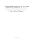
communications
<
V
personality
module
a
904
‘
>
control
I
12C
SENTRY-slave
,
personality
V0
bus
module
l
l
|2C peripheral
918“
QC
906
l2C-bus ‘
i
>
908“
a
~
4_port IPM
910
917 a 912
A
personality
_
4-port IPM
4-p0rt IPM
914'“
4-port
_
920“
DC
:
__
terminal-server
I <-_>
pus
AC‘input
power
personality
d I
QC—bus
RJlZ
mo?u e
E
power
1
?
RHZ
power
f
~
external
H |2C_bu5
moiule
4
4
~
chained-slave
bu?_>
-
‘
n ry
mm
power
board
internal
Se t
<_>
922“
|2C
personality
bus
module
\
i
power
I
I TCPAP
SNMP
US 8,489,667 B2
1
2
NETWORK POWER ADMINISTRATION
SYSTEM
prises a long, thin outlet strip body with several independently
controllable power outlet sockets distributed along its length.
RELATED APPLICATIONS AND PATENTS
A power input cord is provided at one end, and this supplies
AC-operating power to relays associated with each of the
This application is a continuation of US. patent applica
tion Ser. No. 10/313,314, ?led Dec. 6, 2002, and titled NET
WORK REMOTE POWER MANAGEMENT OUTLET,
power outlet sockets. The relays are each addressably con
trolled by a microprocessor connected to an internal I2C-bus
serial communications channel. The power-on status of each
relay output to the power outlet sockets is sensed and com
now US. Pat. No. 7,171,461 issued Jan. 30, 2007, which is a
municated back on the internal I2C-bus . A device-networking
continuation-in-part of US. patent application Ser. No.
09/930,780, ?led Aug. 15, 2001, published as US-2002
communications processor with an embedded operating sys
tem translates messages, status, and controls between exter
0002593 -Al on Jan. 3, 2002, and titled VERTICAL
MOUNT NETWORK REMOTE POWER MANAGEMENT
OUTLET STRIP, now US. Pat. No. 7,043,543 issued May 9,
nal networks, the internal I2C-bus, and other ports.
In alternative embodiments of the present invention, a
power manager architecture provides for building-block con
struction of vertical and horizontal arrangements of outlet
sockets in equipment racks. The electronics used in all such
2006, both of which are incorporated herein by reference.
BACKGROUND OF THE INVENTION
1. Field of the Invention
The invention relates generally to remote power manage
ment systems, and more particularly to electrical power dis
variants is essentially the same in each instance. Each of a
plurality of power input feeds has a monitor that can provide
20
current measurements and reports on the internal I2C-bus.
tribution devices and methods for conserving the primary
Each of the power input feeds could be independently loaded
rack-mount spaces in a standard RETMA rack.
with a plurality of addressable-controllable outlets. Each out
2. Description of the Prior Art
Network server “farms” and other network router equip
ment have settled on the use of equipment bays in 19" stan
dard RETMA racks. Many of these server and router farms
let is also capable of measuring the respective outlet socket
load current and reporting those values on the internal I2C
25
and measured load and infeed current. The internal I2C-bus,
are located at telephone company (TelCo) central equipment
of?ces because they need to tie into very high bandwidth
telephone line trunks and backbones. So each TelCo typically
rents space on their premises to the network providers, and
such space is tight and very expensive.
The typical network router, server, or other appliance
bus. Separate digital displays are provided for each monitored
logic power supply, network interfaces, power control mod
ules and relays, etc., could be distributed amongst several
enclosures that have simple plug connections between each,
30
the infeed power source, and the equipment loads in the rack.
An advantage of the present invention is that a network
comes in a rack-mount chassis with a standard width and
remote power management outlet strip is provided that frees
depth. Such chassis are vertically sized in whole multiples of
vertical units (U). Each rented space in the TelCo premises
up vertical rackmount space for other equipment.
Another advantage of the present invention is that a net
work remote power management outlet strip is provided for
has only so much vertical space, and so the best solution is to
35
make best use of the vertical space by ?lling it with the
controlling the operating power supplied to network appli
network appliances and other mission-critical equipment.
ances over computer networks, such as TCP/IP and SNMP.
Two kinds of operating power are supplied to such network
A further advantage of the present invention is that a net
appliances, alternating current (AC) from an uninterruptable
power supply (UPS) or direct from a utility, the second kind is
direct current (DC) from TelCo central of?ce battery sets.
work remote power management outlet strip is provided that
40
Prior art devices have been marketed that control such AC or
A still further advantage of the present invention is that a
DC power to these network appliances. For example, Server
network remote power management outlet strip is provided
for reducing the need for enterprise network operators to
dispatch third party maintenance vendors to remote equip
Technology Inc. (Reno, Nev.) provides operating-power con
trol equipment that is specialized for use in such TelCo pre
mises RETMA racks. Some of these power-control devices
ment rooms and POP locations simply to power-cycle failed
can cycle the operating power on and off to individual net
network appliances.
work appliances.
Such cycling of operating power will force a power-on
reset of the network appliance, and is sometimes needed
when an appliance hangs or bombs. Since the network appli
ance is usually located remote from the network administra
These and many other objects and advantages of the
present invention will no doubt become obvious to those of
50
ordinary skill in the art after having read the following
detailed description of the preferred embodiments which are
illustrated in the various drawing ?gures.
tion center, Server Technology has been quite successful in
marketing power managers that can remotely report and con
trol network-appliance operating power over the Internet and
other computer data networks.
allows a network console operator to control the electrical
power status of a router or other network device.
IN THE DRAWINGS
55
Conventional power management equipment has either
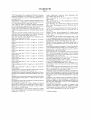
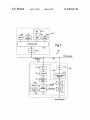
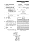
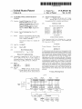
FIG. 1 is a functional block diagram of a network remote
been mounted in the tops or bottoms of the server farm
power management outlet strip embodiment of the present
RETMA racks, and thus has consumed vertical mounting
space needed by the network appliances themselves. So what
invention;
is needed now is an alternate way of supplying AC or DC
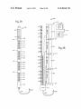
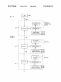
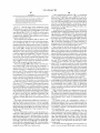
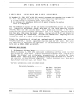
FIG. 2A is a front diagram. of an implementation of the
60
operating power to such network appliances without having
to consume much or any RETMA rack space.
SUMMARY OF THE PRESENT INVENTION
65
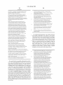
Brie?y, a vertical-mount network remote power manage
ment outlet strip embodiment of the present invention com
network remote power management outlet strip of FIG. 1;
FIG. 2B is an assembly diagram of the network remote
power management outlet strip of FIG. 2A without the sheet
metal enclosure, and shows the interwiring amongst the AC
receptacles, the power input plug, and the various printed
circuit board modules;
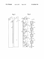
FIG. 3 is a non-component side diagram of a printed circuit
board (PCB) implementation of an intelligent power module
US 8,489,667 B2
3
4
IPT-IPM, similar to those of FIGS. 1, 2A, and 2B, and further
illustrates an insulating sheet that is ?tted to the back;
FIG. 4 is a component-side. diagram of a printed circuit
board (PCB) implementation of an intelligent power module
IPT-IPM, similar to those of FIGS. 1, 2A, 2B, and 3, and
further illustrates the bus connections of the power outlet
receptacles it sockets onto;
reset), and WDSP (Write display). A checksum is used on
received/ sent bytes for data integrity across the I2C-bus.
The IPT-I2C microcontroller starts up with the I2C inter
face in idle slave mode. Main ( ) waits in a loop until the I2C
interface is ?agged as non-idle. After an I2C start occurs, and
the rising edge of SCL sets DRDY (and thus ATN), an I2C
interrupt occurs. The I2C ISR disables the I2C interrupt and
sets a global I2C non-idle ?ag. The main loop then proceeds
FIG. 5 is a functional block diagram of an IPT-NetworkPM
to read in the ?rst byte from the I2C-bus. When seven bits are
module embodiment of the present invention;
received, the target I2C is known and is compared to the
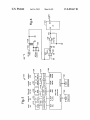
FIG. 6 is a schematic diagram of a circuit that couldbe used
IPT-I2C microcontroller’s own module address. If different,
the I2C interface processing stops and waits for another start
to begin again. If the same, the last bit of the ?rst byte is read,
which is the R/W bit. If a Read, then the IPT-I2C microcon
troller acknowledges the byte and repeatedly sends a ?xed
in an implementation of the IPT-PS of FIGS. 1, 2A, and 2B;
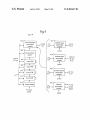
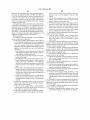
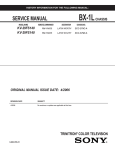
FIG. 7 is a functional block diagram of a network remote
power management system embodiment of the present inven
tion;
FIG. 8 is a functional block diagram of an expandable
power management system embodiment of the present inven
number of response bytes: an address byte, a type byte, one or
more data bytes, and a checksum. If a Write, then the IPT-I2C
tion;
microcontroller acknowledges the byte, and then will read up
FIG. 9 is a functional block diagram of a power distribution
unit embodiment of the present invention; and
to four more bytes: a command byte one or more data bytes,
20
FIG. 10 is a schematic diagram of one way to implement
the IPT-IPM’s in any of FIGS. 1-9.
DETAILED DESCRIPTION OF THE PREFERRED
EMBODIMENTS
valid command, any data parameters and a valid checksum
are received and acknowledged, the command is acted upon.
Without a valid checksum, the command is not acted upon. If
25
stopped, and another start is needed to begin again. Through
30
out the I2C processing loop, a bus timeout (by Timer 1 inter
rupt) resets the I2C interface to idle and the I2C processing
loop to the appropriate states Timer U also guards the I2C
interface with a 5-millisecond inter-clock timeout and a 15
second total I2C timeout. The total I2C timeout is reset when
the IPT-I2C microcontroller is addressed on the I2C with its
from its AC-power input.
Peripheral integrated circuits (IC’s) that have to commu
an unexpected command or data is received, or more bytes are
received than expected, then a negative acknowledge occurs
after the next byte is received, and the I2C interface is
FIG. 1 represents a network remote power management
outlet strip embodiment of the present invention, and is
referred to herein by the general reference numeral 100. The
outlet strip 100 provides independently managed power to
each of sixteenAC-output receptacles 101-116. A power sup
ply (IPT-PS) module 118 senses and totalizes the combined
current delivered to all the AC-output receptacles 101-116
and a checksum. As received, the bytes are acknowledged and
compared to expected valid commands and data. As soon as a
35
primary address (not the secondary address).
nicate with each other and the outside world can use a simple
The I2C IPT-I2C microcontroller commands include the
bi-directional 2-wire, serial data (SDA) and serial clock
STAT command which sets the IPT-I2C microcontroller to a
read type to STAT. This means that an I2C Read will send four
(SCL) bus for inter-IC (I2C) control developed by Philips
bytes (address, type data checksum) in which the data byte
Semiconductor. The I2C-bus has become a worldwide indus
try-standard proprietary control bus.
40
The IPT-PS module 118 digitally encodes the total AC
read type to RBTN. This means that an I2C Read will send
current information onto an internal I2C-bus 119. The IPT-PS
module 118 supplies DC-operating power for the internal
I2C-bus 119 which is derived from the AC-power input. Each
of four intelligent power modules (IPT-IPM) 120-123 have
four relays (Kl-K4) that switch AC-power from the IPT-PS
four bytes (address, type, data, checksum) in which the data
byte represents the status of the button.
45
module 118 to respective ones of the sixteen AC-output
receptacles 101-116. Such relays K1-K4 are controlled by a
?ve bytes (address, type data, data, checksum) in which the
probe data.
50
troller status byte.
An I2C-module (IPT-I2C) 124 receives digital messages
The WDSP command sets the values for the dual seven
55
command is received. After that, if ten seconds pass without
receiving a valid WDSP command, the display reverts back to
current caused by plugging or unplugging a load from any or
the blinking dash-dash.
all of the AC-output receptacles 101-116.
interface to a dual seven-segment display. Port-0 pins select
the illuminated segments of a seven-segment display. Pin
Pl .7 selects which of the two seven-segment displays is being
driven, and alternates between the two seven-segment dis
plays fast enough to avoid ?icker. The I2C slave address is
segment display.
At power up, the dash-dash blinks until a valid WDSP
totalized combined current, e. g., in AC-amperes, on an LED
readout 126. A user is thus able to see the effect on the total
The Philips 87LPC762 microcontroller is used as an I2C
The CRST command clears the Reset Flag (RSTF), Power
On Reset Flag (PORF), Brownout Reset Flag (BORF), and
WatchDog Reset Flag (WDRF) bits of the IPT-I2C microcon
relays K1-K4.
on the internal I2C-bus 119 and decodes and displays the
The RPRB command sets the IPT-I2C microcontroller
read type to RPRB. This means that an I2C Read will send
data bytes represent the type of l-wire bus probe and the
single I2C transceiver daisy-chain connected to others along
the internal I2C-bus 119. Each such I2C transceiver is inde
pendently addressable on the I2C-bus 119, and provides a
digitally encoded power-on status indication for all four
represents the status of the IPT-I2C microcontroller.
The RBTN command sets the IPT-I2C microcontroller
60
A read command is started by the master addressing the
slave with the R/W bit set. A read command to the slave
IPT-I2C microcontroller results in a ?xed number of bytes
repeatedly being transmitted by the slave (address, type,
datal . . . dataN checksum). The ?rst byte is the address of the
con?gurable. Five commands are supported: STAT (status)
slave. The second byte indicates the type of data in the fol
lowing data byte(s). The last byte is a checksum of all the
RBTN (Read button), RPRB (Read probe), CRST (Clear
previous bytes.
65
US 8,489,667 B2
5
6
A write command is started by the master addressing the
slave with the R/W bit cleared. This is followed by the master
transmitting multiple bytes to the slave, followed by a stop, or
global I2C non-idle ?ag. The main loop then proceeds to read
in the ?rst byte from the I2C-bus. When seven bits are
restart.
The internal I2C-bus 119 is terminated at a network per
5
sonality module (IPT-NetworkPM) 128. Such provides an
operating system, HTTP-server, and network interface
between the internal I2C-bus 119, an external I2C-bus 130, an
Ethernet 10/100 BaseT 132, a modem 134, and a local opera
tor’s console 136. The IPT-NetworkPM 128 preferably uses
received, the target I2C is known and is compared to the I/O
Expander’s own module address. If different, the I2C inter
face processing stops and waits for another start to begin
again. If the same the last bit of the ?rst byte is read, which is
the R/W bit. If a Read, then the microcontroller acknowledges
the byte, and repeatedly sends a ?xed number of response
bytes (an address byte, a type byte one or more data bytes, and
a checksum). If a Write, then the microcontroller acknowl
Internet protocols like TCP/IP and supports simple network
management protocol (SNMP). In one application, the outlet
edges the byte and then will read up to three more bytes (a
command byte, a data byte, and a checksum). As received, the
bytes are acknowledged and compared to expected valid
strip 100 could be used in the remote power management
environment described by the present inventors in their US.
Pat. No. 5,949,974, issued Sep. 7, 1999. Such Patent is incor
commands and data. As soon as a valid command, any data
parameters and a valid checksum are received and acknowl
porated herein by reference.
edged, the command is acted upon. If an unexpected com
Network messages, e.g., using TCP/IP and SNMP, are
mand or data is received, or more bytes are received than
communicated over the Ethernet 10/ 100 BaseT interface 132.
expected, then a negative acknowledge occurs after the next
Such messages are able (a) to independently control the
byte is received, and the I2C interface is stopped and another
start is needed to begin again. Throughout the I2C processing
loop, a bus timeout by Timer 1 interrupt resets the I2C inter
face to idle and the I2C processing loop to the appropriate
power on-off to each ofAC-output receptacles 101-116, (b) to
20
read the power-on status of each, and (c) to report load current
supplied by each outlet, or simply the total combined current
measured passing through IPT-PS 118.
In one embodiment, the power applied to AC-output recep
tacles 101-116 is not allowed by the individual IPT-IPM
state. Timer 0 also guards the I2C interface with a 5-millisec
ond inter-clock timeout and a l5-second total I2C timeout.
modules 120-123 to be simultaneously applied. Instead, each
The total I2C timeout is reset when the I/O Expander is
addressed on the I2C with its primary address, not the sec
is allowed to turn on in succession so any instantaneous load
ondary address.
in-rush currents can not combine to exceed the peak capabili
The I2C microcontroller commands include the STAT
command, which sets the I/O Expander read type to STAT. An
ties of the AC-power input source.
The total input current display 126 could be used to advan
tage by a technician when installing or troubleshooting a
25
30
RETMA equipment rack by watching how much current
change is observed when each network appliance is plugged
RCFG. This means that an I2C Read will send four bytes:
in and turned on. Unusually high or low currents can indicate
particular kinds of faults to experienced technicians.
35
which is referred to herein by the general reference numeral
(address, type, ADCE status, ADCO data, ADCI data, ADC2
data, ADC3 data, checksum) in which the data bytes represent
200. These illustrate one way the network remote power
40
implemented and arranged. The outlet strip 200 provides
independently managed power to each of sixteen AC-output
receptacles 201-216. These have AC-neutral and AC-ground
bussed through two sets of eight, e.g., with l2-gauge wire. A
power supply (IPT-PS) module 218 is daisy-chained in an
cycles. All four channels are converted once during each
1.042 ms, about 260 us apart. After four AC (60 HZ) cycles,
each channel has be converted 64 times. For each channel
these 64 conversions are averaged and stored. The most
modules (IPT-IPM) 220-223. The IPT-PS module 218 has, for
example, a Philips microcontroller type 87LPC762 that
recent eight stored averages are then again averaged, making
senses and totalizes the combined current delivered on the
50
IPM) 220-223.
The Philips 87LPC762/7 microcontroller is programmed
the reported value the truncated average over 64x8:5l2 AC
cycles, which spans just over a half second.
The CRST command clears the ReSeT Flag (RSTF) Power
On Reset Flag (PORF), BrownOut Reset Flag (BORF), and
IiiatchDog Reset Flag (WDRF) bits of the I/O Expander
status byte.
as an I2C 8-bit I/O Expander, with an 8-bit 4-channel A/D
converter. Eight pins are individually selectable as either an
Input (quasi-bidirectional) or Output (open drain). Four
the value of the four ADC channels. For ADC channels that
are disabled, a value of 0><FF is returned. For enabled ADC
channels, the value represents the average of the last eight
averages of 64 A/D conversions during the last four AC
internal I2C-bus 219 to a series of four intelligent power
AC-Line leads to all of four intelligent power modules (IPT
address, type, data, checksum. The data byte represents the
I/ O con?guration of the eight I/ O pins.
The RADC command sets the microcontroller read type to
RADC. This means that an I2C Read will send eight bytes
FIGS. 2A and 2B represent a network remote power man
agement outlet strip embodiment of the present invention,
management outlet strip 100 of FIG. 1 could be physically
I2C Read will send four bytes: address, type, data, checksum.
The data byte represents the status of the I/O Expander.
The RCFG command sets the I/O Expander read type to
55
The WCFG command sets the microcontroller I/O con
address lines determine the I2C slave address. Eight com
?guration of the eight I/O pins. The WCFG command also
mands are supported: STAT (Status), RCFG (Read Con?g)
sets the read type to RCFG.
The WPRT command sets the state of the eight I/O pins that
RPRT (Read Port), RADC (ReadADC), CRST (Clear Reset),
WCFG (Write Con?g), WPRT (Write Port), and ADCE
are con?gured as outputs. The WPRT command also sets the
read type to RPRT.
The ADCE command enables or disables any or all four
ADC channels. The ADCE command also sets the read type
(ADC Enable). A checksum is used on received/ sent bytes for
data integrity across the I2C-bus. Without a valid checksum,
a command will not be acted upon.
The microcontroller starts up with the I2C interface in idle
to RADC.
A read command is started by the master addressing the
slave mode. Main( ) waits in a loop until the I2C interface is
edge of SCL sets DRDY and thus ATN, an I2C interrupt
slave with the R/W bit set. A read command to the slave
IPT-I2C microcontroller results in a ?xed number of bytes
occurs. The I2C ISR disables the I2C interrupt and sets a
repeatedly being transmitted by the slave (address, type,
?agged as non-idle. After an I2C start occurs, and the rising
65
US 8,489,667 B2
7
8
datal . . . dataN checksum). The ?rst byte is the address of the
and 404, a PCB trace 406 distributes AC-Line power input
slave. The second byte indicates the type of data in the data
bytes that follow. The last byte is a checksum of all the
from AC-Line screw connector 304 connect at a via 408 to a
previous data bytes.
ler 414 processes the 12C communications on the internal
A write command is started by the master addressing the
slave with the R/W bit cleared. This is followed by the master
l2C-bus, e.g., l2C-bus 119 in FIG. 1 and 219 in FIGS. 2A and
2B.
FIG. 5 shows the basic construction of an lPT-NetworkPM
module 500, and is similar to the lPT-NetworkPM module
128 of FIG. 1 and 228 of FIGS. 2A and 2B. A NetSilicon
series of four power control relays 410-413. A microcontrol
transmitting multiple bytes to the slave, followed by a stop or
restart.
The lPT-PS module 218 digitally encodes the total AC
input current information onto the internal l2C-bus 219. The
lPT-PS module 218 derives DC-operating power from the
AC-power input for modules on the internal l2C-bus 219.
(Waltham, Mass.) type NET+50 32-bit Ethernet system-on
chip for device networking is preferably used to implement a
communications processor 502. A ?ash memory 504 pro
vides program storage and a RAM memory 506 provides
Each of the lPT-lPM modules 220-223 has four relays. (K1
K4) that switch the AC-Line from the lPT-PS module 218 to
buffer and scratchpad storage for the communications pro
cessor operations. A local l2C-bus is implemented in part
with a pair of 2N7002 transistors, for example. It connects
respective ones of the AC-Line connections on each of the
sixteen AC-output receptacles 201-216. Such relays K1-K4
are controlled by a single 12C transceiver located on each
into the 12C daisy chain with a J l -connector (CON4) 510. An
lPT-IPM 220-223. For example, such 12C transceiver could
be implemented with a Philips microcontroller type
87LPC762.
Each such 12C transceiver is independently addressable on
the l2C-bus 219, and provides a digitally encoded power-on
status indication for all four relays K1-K4. An l2C-module
(lPT-I2C) 224 receives digital messages on the internal l2C
bus 219 and decodes and displays the totalized combined
external l2C-bus is implemented inpart with a pair of 2N7002
20
25
current, e.g., in AC-amperes, on an LED-readout 226. The
internal l2C-bus 219 terminates at a lPT-NetworkPM 228.
502 is provided by a physical layer (PHY) device 516. An
Preferably, lPT-NetworkPM 228 includes an operating
system, an HTML webpage, and a network interface. Such
can connect a remote user or command console with the 30
internal l2C-bus 219, an external l2C-bus that interconnects
ernet 10/100 BaseT RJ-45 type socket 232, etc. The lPT
NetworkPM 228 preferably uses lntemet protocols like TCP/
35
(SNMP).
A complete OS kernel, NET+Management simple network
management protocol (SNMP) MlBll and proxy agent,
ily of personality modules to be substituted for lPT-Net
40
The manufacturability and marketability of lPT-lPM 220
223 could be greatly enhanced by making the hardware and
45
sorts out for itself how many lPM’s are connected in a group
and how to organize their mutual handling of control and
status data in and out.
FIG. 3 illustrates a printed circuit board (PCB) implemen
tation of an intelligent power module lPT-IPM 300, similar to
those of FIGS. 1, 2A, and 2B. On the component side of the
PCB, the lPT-IPM 300 has a two-position connector 302 for
AC-Neutral, and on the non-component side screw connector
304 for the AC-Line. A PCB trace 306 distributes AC-Line
power input to a series of four power control relays, as shown
in FIG. 4. An insulator sheet 310 screws down over the lPT
50
implementation of the lPT-PS 118 of FIG. 1 and lPT-PS 218
of FIGS. 2A and 2B. An AC-Line input 602 from the AC
power source is passed through the primary winding of an
isolation transformer 604. A set of four AC-Line outputs 606
are then connected to the four lPT-lPM’s, e.g., 120-123 in
FIG. 1 and 220-223 in FIGS. 2A and 2B. The voltage drop
across the primary winding of isolation transformer 604 is
relatively small and insigni?cant, even at full load. So the line
voltage seen at the AC-Line outputs 606 is essentially the full
input line voltage.
55
lPM 300 and protects it from short circuits with loose wires
A voltage is induced into a lightly loaded secondary wind
ing that is proportional to the total current being drawn by all
the AC-loads, e.g., AC-receptacles 101-116 in FIG. 1 and
201-216 in FIGS. 2A and 2B. An op-amp 608 is con?gured as
a precision recti?er with an output diode 610 and provides a
and the sheetmetal outlet strip housing.
For example, insulator sheet 310 can be made of MYLAR
plastic ?lm and may not necessarily have a set of notches 312
and 314 that provide for connector tabs 302 and 304. Con
nector tabs 302 and 304 can alternatively be replaced with a
two-position connector with screw fasteners.
FIG. 4 illustrates the component side of a PCB implemen
tation of an lPT-lPM module 400, e. g., the opposite side view
of the lPT-lPM module 300 in FIG. 3. The lPT-lPM module
400 comprises a pair of 12C daisy chain bus connectors 402
NET+Protocols including TCP/IP, NET+Web HTTP server,
and XML microparser, are commercially available from Net
Silicon for the NET+50 32-bit Ethernet system-on-chip.
FIG. 6 represents a circuit 600 that could be used in an
software implementation of each the same as the others.
When a system that includes these is operating, it preferably
The ?ash memory 504 is preferably programmed. with an
operating system and HTML-browser function that allow
web-page type access and control over the Ethernet channel.
The modular construction of outlet strip 200 allows a fam
workPM 228. Each such would be able to communicate with
and control the lPT-lPM’s 220-223 via the internal l2C-bus
219.
Intel type LXT971A fast Ethernet PHY transceiver, for
example, could be used together with an R145 connector 518.
A pair of RS-232 serial interfaces are implemented in part
with an SP3243E transceiver 520, an RJ4SH connector 522,
another SP3243E transceiver 524, and an IDC10 connector
526.
with other outlet strips through a RJ-ll socket 230, an Eth
IP and supports simple network management protocol
transistors, for example. It connects into an external 12C
system with an RJl2-type J7-connector 510. Such external
12C system can expand to one additional outlet strip that
shares a single lPT-NetworkPM module 500 and a single
network connection.
An Ethernet 10/100 BaseT interface with the media access
controller (MAC) internal to the communications processor
60
DC-voltage proportional to the total current being drawn by
all the AC-loads and passing through the primary of trans
former 604. An op-amp 612 ampli?es this DC-voltage for the
correct scale range for an analog-to-digital converter input
(A0) of a microcontroller (uC) 616. A Philips Semiconductor
65
type P87LPC767 microcontroller could be used for uC 616.
Such includes a built-in four-channel 8-bit multiplexed A/D
converter and an 12C communication port. When a READ
ADC command is received on the 12C communication port,
US 8,489,667 B2
10
The I2C address of the quad-IPM’s were determined by the
the A0 input is read in and digitally converted into an 8-bit
report value which is sent, for example, to LED display 126 in
version of LPC code on the IPT-PS board, as determined by a
FIG. 1.
read of the STATus byte of the of the IPT-PS.
A prototype of the devices described in connection with
FIGS. 1-6 was constructed. The prototype was a combination
of new hardware and software providing for a 4-outlet, 8-out
let, or 16-outlet vertical-strip power manager that could be
Version 3+ =>
quad—IPM’s start @ 0x60 and were 0x60, 0x62,
0x64, 0x66, 0x68, 0x6A, 0x6C, 0x6E, 0x70,
0x72, 0x74, 0x76, 0x78, 0x7A, 0x7C, 0x7E.
accessed out-of-band on a single RJ45 serial port, or in-band
Version 2— =>
over a 10/ 100Base-T Ethernet connection by Telnet or an
quad—IPM’s start @ 0x40 and were 0x40, 0x42,
0x44, 0x46, 0x48, 0x4A, 0x4C, 0x4E, 0x50,
HTML browser. An R112 port was connected to a second,
nearly identical vertical-strip power manager that was almost
entirely a slave to the ?rst, e.g., it could only be controlled
by/via the ?rst/master vertical power manager.
Up to four IPT-I2C peripheral/display boards were sup
ported at I2C addresses: 0x50, 0x52, 0x54, and 0x56.
Vertical power manager hardware and software was used
There was a direct mapping relationship between power
for the IPT-PS power supply board, the IPT-IPM quad-outlet
boards, and IPT-I2C peripheral/display board. For the master
inputs, IPT-I2C peripheral/ display boards I2C addresses, and
the IPT-IPM boards I2C addresses:
vertical power manager, new personality module hardware
and software was developed. This personality module, trade
marked SENTRY3, was based upon the NetSilicon
20
NetARM+20M microprocessor, and provided all of the con
trol and user interface (UI). On the slave vertical power man
ager, a preexisting IPT-Slave personality module was modi
?ed slightly to bridge the external and internal I2C-buses.
This allowed the master to control the slave vertical power
25
manager exactly the same as the master vertical power man
ager, with no software or microprocessor needed on the slave.
New software couldbe included to run in a microprocessor on
30
only.
A new SENTRY3 personality module was developed to
support an HTML interface for Ethernet, and a command-line
interface for Telnet and serial. Multiple users were supported,
up to 128. One administrative user (ADMN) existed by
default, and will default to having access to all ports. Outlet
grouping was supported, with up to 64 groups of outlets.
at mo st four quad-IPM’ s per input, and with each input having
its own load measurement and display. Each power input was
required to have the same number of quad-IPM’s that it
powered. There was one I2C peripheral/display (IPT-I2C)
board for each power input. Each bus had only one smart
power supply (IPT-PS) board at I2C address 0x5E. Each bus
had at least one I2C peripheral/ display (IPT-I2C) board at I2C
address 0x50, and at least one quad-IPM (IPT-IPM) board at
35
40
(subtract 0x20 for v2—)
A
B
C
D
0x50
0x52
0x54
0x56
0x60, 0x62, 0x64, 0x66
0x68, 0x6A, 0x6C, 0x6E
0x70, 0x72, 0x74, 0x76
0x78, 0x7A, 0x7C, 0x7E
four input feeds, and that there were two I2C-buses, an
addressing scheme for a port must include three ?elds (a) Bus
The Bus ID could be regarded as vertical-strip power man
ager/enclosure ID, since one I2C-bus were for the intemal/
local I2C vertical power manager components and the other
I2C-bus were for the external/remote vertical power manager.
Other implementations could use a CAN bus in place of the
external I2C-bus. Each enclosure had an address on the bus,
e.g., an Enclosure ID. Thus, the three address ?elds needed
were (a) Enclosure ID, (b) Input Feed ID, and (c) Relay ID.
The Enclosure ID was represented by a letter, starting with
“A”, with a currently unde?ned maximum ultimately limited
to “Z”. Only “A” and “B” existed for the prototype. The Input
45
Feed ID was represented by a letter, with a range of “A” to
“D”. The Relay ID was represented by a decimal number,
with a range of“1” to “16”.
An absolute identi?er was needed for the user to enter
I2C address 0x60 (or 0x40).
Determining what was present on an I2C-bus, and at what
IPT—IPM v3+ addresses
address
ID, (b) Input Feed ID, and (c) Relay ID
There were two I2C-buses that can support up to sixteen
quad-IPM (IPT-IPM) boards, across four power inputs, with
IPT—I2C
Input
Considering that each input power feed can support up to
four quad-IPM’s (sixteen ports), and that each bus can have
the slave vertical power manager personality module to act as
a backup master for load-display and power-up sequencing
Power
commands. A combination of Enclosure ID, Input Feed ID,
50
address, was done by reading the 8-bit. I/O port of the power
supply. The eight bits were con?gured as,
and Relay ID must be expressed in the absolute ID. This were
done with a period followed by two alphabet characters and
then one or two numeric characters, e.g., “.{enclosure_id}
[input_feed_id] (#1 [#1 "~
Bit 0 =>
Bit 1 =>
Unde?ned
55
Display Orientation (l = Upside-Up,
Input Feed ID (“A” to “D”). The third and fourth number
0 = Upside—Down)
Bit 2 =>
Bit 3 =>
Bit four =>
Number of quad—IPM’s per power input
Number of quad—IPM’s per power input
overload point (1 = 30.5 A [244ADC],
Bit 5 =>
0 = 16.5 A [132ADC])
Unde?ned
Bit 6 =>
Bit 7 =>
Number of power inputs
Number of power inputs
The ?rst alphabet character represented the Enclosure ID
(“A” to “Z”). The second alphabet character represented the
characters represented the Relay ID (“1” to “16”),
60
e.g., "-(“$Z)[A@lll§15>"~ The input feed ID was optional. If not
speci?ed, “A” was assumed. With an absolute ID scheme, a
period, letter, and number must always be entered, making it
very similar to our current scheme, but allowing for future
multiple input feeds. For displaying IDs, the optional input
feed ID should only be shown when the port was in an enclo
Bits 2 & 3 together determine how many quad-IPM’s there
were per power input. Bits 6 & 7 together determine how
many power input feeds there were.
65
sure with 2 or more input feeds. A vertical power manager ID
could be speci?ed with just a period and letter. An input feed
ID could be speci?ed with a period and two letters.
US 8,489,667 B2
11
12
Existing outlets were determined by reading the power.
-continued
supply I/ O port of the master and slave vertical power man
ager. One administrative user exists by default, and has access
to all outlets and groups. This administrator (ADMN) could
12C Address
12C Address
Device
(binary)
(hex)
be removed, but only if one or more other users with admin
istrative privileges exist. Additional users could be created or
lZC—O4
OlOl —Ollx
0x56
lPT—PS
OlOl — lllx
Ox5E
removed. Administrative privileges could be given to or
1PM — 01
0110 — 000x
0x60
removed from added users.
1PM — 02
0110 — 001x
0x62
lPM—O3
IPM—O4
OllO—Ole
OllO—Ollx
0x64
0x66
The administrative privilege allows access to all currently
detected outlets and groups without those outlets or groups
actually being in the user’s outlet or group tables. Lists of
outlets or groups for administrative users should include all
currently-detected outlets and groups. This allowed adminis
trative privileges to be given or taken away without affecting
the users outlet and group tables.
Groups of outlets could be created or removed. Outlets
could be added or removed from groups. Outlets, or groups of
outlets, could be added or removed from users. An outlet may
belong to multiple groups. All user-de?ned outlet and groups
names were unique. This were enforced at the time names
were de?ned by the user. All user-de?ned names also cannot 20
be the same as any KEYWORDS. For example, they cannot
be “GROUP”, “OUTLET”, or “ALL”. This were enforced at
1PM — O5
0110 — 100x
0x68
IPM—O6
IPM—O7
IPM—08
0110— lle
OllO—lle
OllO—lllx
Ox6A
Ox6C
Ox6E
1PM — O9
0111 — 000x
0x70
IPM—lO
lPM—ll
IPM—lZ
Olll—Ole
Olll—Ole
Olll—Ollx
0x72
0x74
0x76
1PM — 13
0111 — 100x
0x78
1PM — 14
0111 — lle
Ox7A
lPM—l5
IPM—l6
Olll—lle
Olll—lllx
Ox7C
Ox7E
The prototype required several major software compo
the time names were de?ned by the user. Usemames were
nents to be constructed for use with the NetSilicon NET+50
uppercased when stored and displayed, and were compared
device. The con?guration and operational control blocks used
case-insensitive. Passwords were stored and compared case
sensitive. Separate tables existed for each user’s outlet access
25
and group access.
When an ADMN user speci?es “ALL” it means all cur
rently detected outlets. For non-ADMN users, the “ALL”
were modi?ed, the modi?cations were mirrored in EEPROM
parameter refers to all of the outlets in the current user’ s outlet
access table. There was no “all” to refer to all groups.
30
All commands that specify outlet IDs need to be bounds
where copies of these control blocks were stored. The opera
tional control blocks were also accessible to all components
for read access, but each operational control block has an
“owner” that performs all writes to the operational control
checked against the currently detected number of enclosures,
number of input feeds on the target enclosure, and the number
of relays on the target enclosure. Power actions could be
applied to only one target at a time. The target could be an
in the prototype were described in the following tables. All of
the control blocks were readable by all components in the
system. The con?guration control blocks were written by the
user interface tasks. When the con?guration control blocks
35
blocks. If a non “owner” wishes to change an operational
control block, a signal or message was used to let the “owner”
outlet or a group of outlet.
know the control block should be updated.
A wakeup state determined the default power-up state of
each outlet. Power-on sequencing occurred independently on
each vertical power manager and power feed, with each outlet
being initialized to its wakeup state two seconds after the
ing and documenting the external 12C protocol that was used
The major design tasks for the prototype included design
40
previous outlet, e.g., starting with outlet-l. Outlet names
could be up to 24-characters. These were stored and displayed
case-sensitive, but were compared case-insensitive as com
mand parameters. Group names could be up to 24-characters.
These were stored and displayed case-sensitive, but were
compared case-insensitive as command parameters. A
24-character vertical power manager/enclosure name could
be user-de?ned. This were stored and displayed case-sensi
tive, but was compared case-insensitive as a command param
eter. A 32-character location name could be user-de?ned.
This were stored and displayed case-sensitive. Usernames
could be 1-16 characters, and were case-insensitive. Pass
words also could be 1-16 characters, and were case-sensitive.
to communicate to “chained” SENTRY boxes, and the new
command line interface commands to support features that
were previously available only via the SENTRY SHOW
Screen interface. The HTML code was developed for the
prototype, as well as the “slave” SENTRY code to run in a
45
personality module of a “chained” SENTRY. Further discrete
50
design efforts were required to code the system initialization,
the local 12C task, the external 12C task, the serial port control
task, the telnet control task, the user interface task, the power
coordination task, the extem user interface (button/LED)
control task, and the WEB control task.
The major software components developed for the proto
type are listed in the following Tables.
Variable length command parameters were length-checked
for validity. An error was displayed if too short or too long, as
opposed to and automatic behavior, such as truncating a string
that was too long.
55
SenlNIT — SENTRY initialization procedure. This software was
the ?rst SENTRY software that executes. It performs hardware,
software (builds the Con?guration and Operational global
Prototype 12C Address Map
control blocks), and OS initialization. This code spawns the
SENTRY operational tasks that provide the system services.
60
12C Address
12C Address
Device
(binary)
(hex)
lZC—Ol
IZC—OZ
IZC—O3
OlOl —000x
0101 —Ole
0101 —Ole
0x50
0x52
0x54
TskSER — One instance of this task was spawned for each
active serial port. In the initial product there was one
instance of this task. This task spawns TskUSR when a logon
was detected. This task owns the serial port operational array
control block in global memory. This control block was updated
to re?ect the status of the serial port. Once a TskUSR was
spawned, this task performs serial port monitoring functions
65 and if modern status signal indicate a lost connection, this
task will signal TskUSR (via an OS interface) of this event.
US 8,489,667 B2
14
13
-continued
TskTELNET — One instance of this task was spawned to listen
SENTRY Con?guration Table (SCT) — This control block
for telnet connections. When a connection was detected, this
task spawns TskUSR for the connection.
TskFTP — One instance of this task was spawned to listen for
FTP connections. The function of this task was to provide
contains global con?guration information. There was a single
instance ofthis control block.
Username/Password Array (UNP) — This was an array of control
blocks with each entry representing a user de?ned to the
system. System locks were used to serialize access to this
array when adding/deleting users. There was room for sixty—
four entries in this array.
Intelligent Power Module (IPM) Array — This was an array of
control blocks with each entry representing an IPM de?ned to
the system. There was room for 32 entries in this array.
Power Control Relay (PCR) Array — This was an array of
control blocks with each entry representing an PCR de?ned to
the system. There was room for 128 entries in this array.
Group Power Control Relay (GRP) Array — This was an array of
?eld software updates for the system. The mechanism used was
determined based on the developer kit capabilities.
TskWEB — This task was to provide WEB access via the system
provided WEB server. The mechanism and number of instances of
this task was determined based on the developer kit
capabilities.
Tsk12C — There were two versions of this task; the local
version that controls internal 12C connections and the global
version that controls external 12C connections. For the ?rst
implementation there were two instances of this task, one to
control the single 12C internal connection and one to control
control blocks with each entry representing an Group of PCRs.
There was room for 64 entries in this array.
Serial Port (SER) Array — This was an array ofcontrol blocks
the single 12C external connection. These tasks implement the
protocol for communicating control requests from the system to
with each entry representing a serial port that can be used to
the 12C connected devices. Control requests were received via
system signals or messages (depending on the OS capabilities)
from the power control coordinating task (TskPCntl) for power
control requests and from the external user interface task
(TskEUI) for LED control requests. This task communicates
power control status updates received from the IPM’s to
TskPCntl and external button status updates to TskEUI using
access the system. There was room for two entries in this
array.
20
entries in this array.
system signals or messages as necessary.
TskPCntl — This was the power control coordinating task.
There was one instance of this task. This task receives power
12C Array — This was an array of control blocks with each
entry representing an 12C connection. There was room for two
25
The Global RAM Operational Control Block Structures
were globally addressable by all software in the system.
control request from the user interface tasks (TskUSR and
These data structures exist only in RAM and are lost during a
TskWEB) via system provided signals or messages and passes
them to the correct 12C task (internal or external) using
system restart. They were constructed during system initial
ization using current operational values. All software has read
signals or messages. This task receives status updates from
the 12C tasks via signals or messages. TskPCntl “owns” the
IPMO and PCRO arrays and it updates the status ?elds in
entries in these arrays as necessary.
30
current operational status of devices in the system. Each of
these control blocks has an “owner” task that performs
TskEUI — This was the external user interface task that
handles the push button functions and the LED display
functions for the system. This task communicates with the
local Tsk12C via signals or messages to update the LED. Tsk12C
sends signals or messages to this task when the state of the
access to all of the data structures. The data in these control
blocks was operational data and was changed to re?ect the
35
updates by writing to the control block. There were six global
operational control blocks as illustrated below. Complete
descriptions of each control block structure follows.
external push button changes.
TskUSR — This command line user interface task was spawned by
TskSER and TskTELNET when a user connection was detected. This
task veri?es the user login and then implements the command
line interface. This routine communicates power control
40
commands via signals or messages to TskPCntl. This routine
Intelligent Power Module (IPMO) Array — This was an array of
control blocks with each entry representing an IPM de?ned to
the system. There was room for 32 entries in this array. The
“owns” the active command line user array. Because there were
entries in this array correspond directly to the IPM
con?guration control block. These control blocks contain
multiple instances of this task, locks were used to serialize
dynamic information that changes regularly. The relay
coordination task (TskPCntl) “owns” this array.
access to the active user array.
TskSYS — This was the general system task. Speci?c functions
for this task were de?ned as development progressed.
45
Power Control Relay (PCRO) Array — This was an array of
control blocks with each entry representing an PCR de?ned to
the system. There was room for 128 entries in this array.
The entries in this array correspond directly to the PCR
con?guration control block. These control blocks contain
The control blocks were globally addressable by all soft
ware in the system. Such data structures exist in RAM and
were mirrored in EEPROM memory. They were constructed
dynamic information that changes regularly. The relay
50
during system initialization using the non volatile versions in
EEPROM memory. If the EEPROM memory was empty, the
control blocks were built using defaults and the EEPROM
memory was initialized using defaults as well. All software
has read access to all of the data structures. The data in these
control blocks was con?guration data and was only changed
as a result of con?guration updates. The data was mostly
static and was written during initialization and when con?gu
ration changes occur during an authorized user session. All
55
the prototype.
2 entries in this array. The entries in this array correspond
directly to the 12C con?guration control block. These
control blocks contain dynamic information that changes
regularly. The 12C task (TskIZC) “owns” this array.
Serial Port (SERO) Array — This was an array of control
blocks with each entry representing a serial port that can be
used by the system. There was room for two entries in this
array. The entries in this array correspond directly to the
serial port con?guration control block. These control blocks
60
contain dynamic information that, changes regularly. The
serial port task (TskSER) “owns” this array.
Active Command Line User (UCLI) Array — This was an array of
write access to this data consists of a two step process where
the Global RAM copy of the data was updated followed by an
update of the EEPROM copy of the data. There were seven
global con?guration control blocks as illustrated below. The
following Tables describe each control block structure used in
coordination task (TskPCntl) “owns” this array.
12C (IZCO) Array — This was an array ofcontrol blocks with
each entry representing an 12C connection. There was room for
control blocks with each entry representing a current active
command line user ofthe system. The SCT was room for 5
65
entries in this array. These control blocks contain dynamic
information that changes regularly. The user interface task
(TskUSR) “owns” this array. There were multiple instances of
TskUSR so locks were used for this array.
US 8,489,667 B2
15
16
If the computer-based appliance 714 is a conventional
-continued
piece of network equipment, e.g., as supplied by Cisco Sys
tems (San Jose, Calif), there will usually be a great deal of
Active HTTP Interface User (UHTP) Array — This was an array
of control blocks with each entry representing a WEB user.
There was room for 5 entries in this array. These control
pre-existing SNMP management software already installed,
e.g., in host 702 and especially in the form of SNMP 740. In
such case it is usually preferable to communicate with the
blocks contain dynalnic information that changes regularly.
The WEB task (TskWEB) “owns” this array.
protocol stack 722 using SNMP protocols and procedures.
Alternatively, the Telnet application 736 can be used to con
trol the remote site 706.
In FIG. 7, a network remote power management system
700 includes a host system 702 connected over a network 704
An ordinary browser application 738 can be implemented
with MSN Explorer, Microsoft Internet Explorer, or Netscape
to a remote system 706.Ap0wer manager 708, e.g., like outlet
strips 100 and 200 ofFIGS. 1, 2A, and 2B, is used to monitor
and control the operating power supplied to a plurality of
computer-based appliances 714 associated with a network
interface controller (NIC) 716.
Such computer-based appliances 714 are subject to soft
NAVIGATOR or COMMUNICATOR. The protocol stack
722 preferably includes the ability to send hypertext transfer
protocol (HTTP) messages to the host 702 in datapackets 726.
In essence, the protocol stack 722 would include an embed
ded website that exists at the IP-address of the remote site
706. An exemplary embodiment of a similar technology is
ware freezing or crashing, and as such can become unrespon
sive and effectively dead. It is also some mission-critical
represented by the MASTERSWITCH-PLUS marketed by
American Power Conversion (West Kingston, RI).
assignment that suffers during such down time. It is therefore
the role and purpose of the network remote power manage
ment system 700 to monitor the power and environmental
20
operating conditions in which the computer-based appliance
714 operates, and to afford management personnel the ability
to turn the computer-based appliance 714 on and off from the
host system 702. Such power cycling allows a power-on
signal. Cisco Systems routers, for example, provide an input
that can be supported in software to issue the necessary mes
sage and identi?er to the system administrator. A device inter
25
Network information is generally exchanged with protocol
data unit (PDU) messages, which are objects that contain
30
can be a user password mechanism. Better than that, it could
include a discrete network ?rewall and data encryption.
The protocol stack 722 interfaces to a remote power man
start-ups or shut-downs. When a user wants to see if a terminal
is attached to the network, for example, SNMP is used to send
35
40
ager 724, and it converts software commands communicated
in the form of TCP/ IP datapackets 726 into signals the remote
45
systems can be used.
Once a user has installed and con?gured the power man
ager 708, a serial communications connection is established.
For example, with a terminal or terminal emulation program.
50
been constructed use a variety of communications access
the protocol stack 722 into appropriate datapackets 726.
Commercial embodiments of the present invention that have
methods.
For modem access, the communication software is
launched that supports ANSI or VTl 00 terminal emulation to
dial the phone number of the external modem attached to the
724. Such serial connection can have a set of intervening
modems that allow the terminal to be remotely located. The
display 730 and keyboard 728 can also be virtual, in the sense
55
that they are both emulated by a Telnet connection over the
network 704.
The host 702 typically comprises a network interface con
troller (NIC) 732 connected to a computer platform and its
operating system 734. Such operating system can include
Microsoft WINDOWS-NT, or any other similar commercial
product. Such preferably supports or includes a Telnet appli
cation 736, a network browser 738, and/or an SNMP appli
cation 740 with an appropriate MIB 742. A terminal emula
tion program or user terminal 744 is provided so a user can
manage the system 700 from a single console.
packet informing them of the shutdown with a trap PDU.
In alternative embodiments of the present invention, it may
be advantageous to include the power manager and intelligent
power module functions internally as intrinsic components of
an uninterruptable power supply (UPS). In applications
from the host 702 that will cause the remote power manager
Locally, a keyboard 728 can be used to select a variety of
readouts on a display 730, and also to control the relay-switch
712.
The display 730 and keyboard 728 can be connected as a
terminal through a serial connection to the power manager
out a read PDU to that terminal. If the terminal is attached, a
user receives back a PDU with a value “yes, the terminal is
attached”. If the terminal was shut off, a user would receive a
where it is too late to incorporate such functionally, external
plug-in assemblies are preferred such that off-the-shelf UPS
power manager can use. For example, messages can be sent
724 to operate the relay-switch 712. In reverse, voltage, cur
rent, and temperature readings collected by the sensor 71 0 are
collected by the remote power manager 724 and encoded by
variables and have both titles and values. SNMP uses ?ve
types of PDU’s to monitor a network Two deal with reading
terminal data, two deal with setting terminal data, and one, the
trap, is used for monitoring network events such as terminal
face controller (NIC) 718, and this may be connected to a
security device 720. If the network 704 is the Internet, or
otherwise insecure, it is important to provide protection of a
protocol stack 722 from accidental and/or malicious attacks
that could disrupt the operation or control of the computer
based appliance 714. At a minimum, the security device 720
rupt has been described here because it demands immediate
system attention, but a polled input port could also be used.
rebooting of software in the computer-based appliance 714 to
be forced without actually having to visit the site. The oper
ating conditions and environment are preferably reported to
the host 702 on request and when alarms occur.
The power manager 708 further includes a network inter
Many commercial network devices provide a contact or
logic-level input port that can be usurped for the “tickle”
60
power manager. When the modems connect, a user should see
a “CONNECT” message. A user then presses the enter key to
send a carriage return.
For direct RS-232C access, a user preferably starts any
serial communication software that supports ANSI or VT100
terminal emulation. The program con?gures a serial port to
one of the supported data rates (38400, 79200, 9600, 4800,
7400, 7200, and 300 BPS), along with no parity, eight data
bits, and one stop bit, and must assert its Device Ready signal
(DTR or DSR). A user then presses the enter key to send a
65
carriage return.
For Ethernet network connections, the user typically con
nects to a power manager 708 through a modem or console
US 8,489,667 B2
17
18
serial port, a TELNET program, or TCP/IP interface. The
user con?guration data for each of its power control ports. A
power manager 708 preferably automatically detects the data
typical implementation had four relay-operated power con
rate of the carriage return and sends a username login prompt
back to a user, starting a session. After the carriage return, a
user will receive a banner that consists of the word “power
trol ports. Part of the user con?guration can include a user
assigned name for each control port.
A resynchronization program is executed in each micro
processor of each power controller board 802, 804, and 806,
that detects where in the order of the daisy-chain that the
manager” followed by the current power manager version
string and a blank line and then a “Usemamez” prompt.
A user logged in with an administrative username can
particular power controller board is located. The appropriate
control power and make con?guration changes. A user logged
main program control loop is selected from a collection of
?rmware programs that are copied to every powers controller
board. In such way, power controller boards may be freely
in with a general username can control power on/off cycling.
Users logged in administrative usemames can control power
to all intelligent power modules, a user logged in with a
general username may be restricted to controlling power to a
added, replaced, or removed, and the resulting group will
resynchronize itself with whatever is present.
The top power controller board 802 uniquely handles inter
speci?c intelligent power module or set of intelligent power
modules, as con?gured by the administrator.
A parent case, US. patent application Ser. No. 09/732,557,
?led Dec 8, 2000, titled NETWORK-CONNECTED
active user log-in, user-name tables, its private port names,
and transfer acknowledgements from the other power con
troller boards. All the other power controller boards concern
themselves only with their private resources, e. g., port names.
POWER MANAGER FOR REBOOTING REMOTE COM
PUTER-BASED APPLIANCES, includes many details on
the connection and command structure used for con?guration
management of power manager embodiments of the present
20
invention. Such patent application is incorporated herein by
lowed by the ?rst outlets con?guration block from power
controller board 802, and the other outlet con?guration
reference and the reader will ?nd many useful implementa
tion details there. Such then need not be repeated here.
Referring again to FIG. 7, a user at the user terminal 744 is
able to send a command to the power manager 724 to have the
25
blocks from power controller boards 804 and 806. The power
controller board 802 tells each when to chime in. Each block
carries a checksum so transmission errors could be detected.
power manager con?guration ?le uploaded. The power man
ager 724 concentrates the con?guration data it is currently
operating with into a ?le. The user at user terminal 744 is also
able to send a command to the power manager 724 to have it
During a user con?guration ?le upload, power controller
board 802 begins a complete message for all the power con
troller boards in the string with the user-table. Such is fol
Each block begins with a header that identi?es the source or
destination, then the data, then the checksum.
During a user con?guration ?le download, power control
30
ler board 802 receives a command from a user that says a
accept a power manager con?guration ?le download. The
con?guration ?le is next. The user-name table and the serial
download ?le then follows. Once downloaded, the power
manager 724 begins operating with that con?guration if there
name table is received by power controller board 802 along
with its private outlets con?guration block and checksum.
The next section is steered to power controller board 804 and
were no transfer or format errors detected. These commands
to upload and download con?guration ?les are preferably
implemented as an extension to an already existing repertoire
of commands, and behind some preexisting password protec
tion mechanism. HyperTerminal, and other terminal emula
35
received. If all power controller boards returned an acknowl
tion programs allow users to send and receive ?les.
In a minimal implementation, the power manager con?gu
it receives its outlets con?guration block and checksum. If
good, an acknowledgement is sent to the top power controller
board 802. The power controller boards further down the
string do the same until the whole download has been
40
edgement, the power controller board 802 acknowledges the
ration ?les are not directly editable because they are in a
whole download. Operation then commences with the con
concentrated format. It would, however be possible to imple
ment specialized disassemblers, editors, and assemblers to
manipulate these ?les off-line.
ration is retained.
FIG. 8 is a diagram of an expandable power management
?guration. Otherwise a fault is generated and the old con?gu
45
system 800 that could be implemented in the style of the
outlet strip 100 (FIG. 1). In one commercial embodiment of
the present invention, a ?rst power controller board 802 is
daisy-chain connected through a serial cable 803 to a second
power controller board 804. In turn, the second power con
troller board 804 is connected through a serial cable 805 to a
third power controller board 806. All three power controller
sockets so that power loading is brought on gradually and not
all at once. For example, power comes up on the power outlet
50
independent power outlet sockets, e.g., for network opera
55
tions center reboot of a crashed network server in the ?eld.
60
erably allows users to design the embodiments to be loaded at
80% of full capacity, versus 60% of full capacity for prior art
units with no sequencing. In some situations, the number of
power drops required in a Data Center can thus be reduced
The power-on sequencing of the power-outlet sockets pref
active webpages. If then connected to the Internet, ordinary
browsers could be used to upload and download user con?gu
rations.
Each power controller board is preferably identical in its
hardware and software construction, and yet the one placed at
the top of the serial daisy-chain is able to detect that situation
with substantial savings in monthly costs.
FIG. 9 represents a power distribution unit (PDU) embodi
ment of the present invention, and is referred to herein by the
general reference numeral 900. The PDU 900 allows a per
and take on a unique role as gateway. Each power controller
board is similar to power controller 208 (FIG. 2). Each power
controller board communicates with the others to coordinate
actions. Each power controller board independently stores
sockets 2-4 seconds apart. An exaggerated power-up in-rush
could otherwise trip alarms and circuit breakers. Embodi
ments display or otherwise report the total current being
delivered to all loads, and some embodiments monitor indi
vidual power outlet sockets. Further embodiments of the
present invention provide individual remote power control of
boards can communicate with a user terminal 808 connected
by a cable 809, but such communication must pass through
the top power controller board 802 ?rst.
Alternatively, the user terminal could be replaced by an
IP-address interface that provided a web presence and inter
In general, embodiments of the present invention provide
power-on sequencing of its complement of power-outlet
65
sonality module 902 to be installed for various kinds of con
trol input/ output communication. For an Ethernet interface, a
NetSilicon type NET+50 system-on-a-chip is preferred, oth