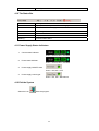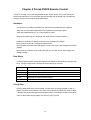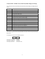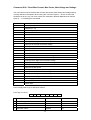
1
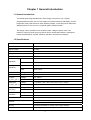
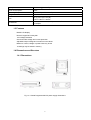
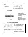
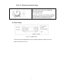
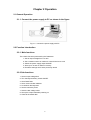
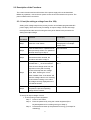
Programmable Power Supply
P6000 V3.0 User’s Manual
CONTENTS
Caution
Safety notes
3
3
Chapter 1 General Introduction
4
1.1 General Introduction
1.2 Specifications
1.3 Features
1.4 Dimensions and Structure
1.4.1 Dimensions
1.4.1.1 Front Panel Components
1.4.1.2 LCD Display
1.4.1.3 Keyboard Layout
1.4.1.4 Rotary Dial and Function Keys
1.4.2 Rear Panel
Chapter 2 Operation
4
4
5
5
5
6
6
6
7
7
8
2.1 General operation
2.2 Function introduction
2.2.1 Main Description
2.2.2 Sub-functions
2.3 Description of the functions
2.3.1 V-set
2.3.2 I-set
2.3.3 Switch ON/OFF power output
2.3.4 Store data function
2.3.5 Recall data function
2.3.6 Menu Description
2.3.6.1 Setting the max output voltage value
2.3.6.2 Set up the key sound
2.3.6.3 Set up the communication
2.3.6.4 Set up communication address (0 - 254)
2.3.6.5 Set up locking key board
2.3.6.6 Set up constant power output
2.3.6.7 Set up save option
2.3.6.8 Set up the output after powering
2.3.6.9 Clear all the saved data
2.3.6.10 Exit function
1
8
8
8
8
9
9
10
11
11
12
12
13
13
13
14
14
15
15
15
16
16
Chapter 3 Power MS Software installation
17
3.1 Software Installation
3.2 Starting the program
3.3 Software Un-installation
17
20
21
Chapter 4 Software Introduction
22
4.1 Software Description
4.2 The COM Port and Power Supply Address Setting
4.3 Starting Communication
4.4 Halting the Communication
4.5 Select POWER
4.6 Select PC to POWER Control instructions
4.7 Set the Voltage Range
4.8 Set the Max Current
4.9 Instrument Indicator panel Description
4.10 The Status Bar
4.11 Power Supply State indicators
4.12 Exit
Chapter 5 Remote control
5.1 Active X module
22
23
25
25
25
25
26
27
27
29
29
29
30
34
2
CAUTION
Before switching on the DC Power supply, the protective ground terminal of this instrument
must be connected to the protective conductor of the AC line power cord. The AC line plug
should be inserted only in a socket outlet with a protective grounding conductor and must not
have an extension cord.
SAFETY NOTES
The following general safety precautions must be observed during all phases of operation,
service and repair of this instrument. Failure to comply with these precautions or with specific
warnings elsewhere in this manual violates safety standards of design, manufacture, and
intended use of the instrument. The Manufacturer assumes no liability for the customer’s
failure to comply with these requirements.
Grounding the Instrument
This product is provided with a protective Ground terminal. To minimize shock hazard, the
instrument chassis and cabinet must be connected to an electrical ground. The
instrument must be connected to the AC power source through a three-conductor power
cable, with the third wire firmly connected to an electrical ground (safety ground) at the
power outlet. For instruments designed to be hard-wired to the AC power lines (supply
mains), connect the protective ground terminal to a protective conductor before any other
connection is made. Any interruption of the protective (grounding) conductor or
disconnection of the protective ground terminal will cause a potential shock hazard that
could result in personal injury. If the instrument is to be energized via an external
autotransformer for voltage reduction, be certain that the autotransformer common
terminal is connected to the neutral of the AC power lines (supply source).
Keep Away From Live Circuits
Operating personnel must not remove the instrument covers. Only qualified service
personnel must make component replacement and internal adjustments. Under certain
conditions, dangerous voltages may exist even with the power cable removed. To avoid
injuries, always disconnect power, discharge circuits and remove external voltage
sources before touching components. Do Not Substitute Parts or Modify Instrument
because of the danger of introduction of additional hazards, do not install substitute parts
or perform any unauthorized modification to the instrument. Return the instrument to a
qualified dealer for service and repair to ensure that safety features are maintained.
3
Chapter 1 General Introduction
1.1 General Introduction
The P6000 series Programmable DC Power Supply is an easy to use, compact
programmable DC power source. This supply incorporates a backlit LCD display, numeric
keypad and rotary code switch for easily inputting voltage, current and power values and
displaying them on the LCD or the computer graphic software screen.
This supply can be operated in the constant current, voltage or power mode. The
maximum current or power limit may also be set for utmost load protection, making this
instrument essential for scientific research, education, and service institutions.
1.2 Specifications
Model No.
P6000
No. Of outputs:
1
Output voltage:
0 to ±36V
Output Current:
0 to 3A DC
Voltage resolution:
1mV from 0 to 3.999V; 10mV from 4 to 36V
Current resolution:
1mA
Constant voltage Line
0-3.999V: 0.01% +3mV; 4V to 36V: 0.02%+10mV
Regulation
Load
Constant Current Line
0.02%+10mV
0.02%+10mA
Regulation
Load
0.02%+10mA
Ripple and noise: Voltage
≤ 1mV Rms
Ripple and noise: Current
≤ 4mA Rms
Voltage
0.1% +20mV
Accuracy (25°C) Current
0.1% +20mV
Read Back
0 – 19.999V: 0.2% +20mV; 20 to 36V: 0.2% + 100mV
Program
Voltage
Accuracy (25°C) Current
0.2% + 20mA
Program
Voltage
0- 3.999V: 1mV; 4-36V: 10mV
Resolution
Current
1mA
Read back
Voltage
0 –19.999V: 10mV; 20 – 36V: 100mV
Resolution
Current
1mA
Communication interface:
Software
RS232 and RS485* * Optional upon request
Power MS Power Management software
DLL support tools for VC++/VB/DELPHI/LABVIEW/COM (upon request)
Memory
10 location EEPROM for saving Power supply settings
Protection
Over voltage/over current/over power
4
Input power
AC110/220 @ (60/50HZ)
Power Consumption:
200VA
Operating Temp
0°C to 50°C (32° F to 120 °F)
Weight
13 lbs
8.3” (L) x 3.5” (H) x 10” (D)
Size
212mm × 88mm × 250mm
Software, users manual, AC power cable, Rack mount kit, RS232 cables
Accessories
and adapter
1.3 Features
Backlit LCD display.
Numeric keypad and rotary dial
1mV Voltage resolution
Over and under voltage and current protection
Adjustable output voltage and constant current values
Maximum current, voltage or power limits may be set
10 settings may be stored in memory
1.4 Dimensions and Structure
1.4.1 Dimensions
Fig 1.4.1 P6000 Programmable DC power supply dimensions
5
1.4.1.1 Front Panel Components
Please see the following picture for
details:
1. LCD Display
2. Numeric Keyboard
3. Rotary Code Switch
4. Output Terminals
Fig 1.4.1.1 Front view of P6000 DC power supply
1.4.1.2 LCD display
Upper Left Corner
Indicates the voltage setting.
(Low-voltage when flashing.)
Indicates output current value.
Indicates output power value. (Flashes
when over power)
Indicates the unit’s present status value:
The possible states are: ON (OFF):
Output ON or OFF
PC (KEY) Indicates if the unit is in the
local mode and keyboard entries may be
Fig 1.4.1.2
made (Key) or under PC control (PC)
OH indicates the power supply is
overheated
1.4.1.3 Keyboard Layout and description
0 to 9: The number keys
Store: Saves the displayed values to memory
Recall: Recalls a setting saved in memory
Menu: Displays the menu
OUT ON/OFF: Turns the output on/off
Fig 1.4.1.3 P6000 Key board Layout
Enter: The confirmation key
V-set: Sets the output voltage value
Enters Voltage and Current values. Special
I-set: Sets the max output current
: The up arrow key, moves menu up
functions (Store, Recall, Menu, etc) may also
: The down arrow key, moves menu down
be entered with the keys printed in blue.
V/A: Displays the output voltage in V and I in A (mps)
mV/mA : Displays the voltage in mV and I in mA
6
Fig 1.4.1.4 Rotary and function keys
Left arrow: Move cursor to next left digit
Right arrow: Move cursor to next right digit
ESC: Exit current menu
OK: Confirmation key
Rotary Dial: Increases or decrease the indicated
value, depending on the direction (Clockwise
increases; Counterclockwise decreases)
1.4.2 Rear Panel
Fig 1.4.1.5 Rear Panel
The fuse can be changed easily by using a small screwdriver. Please use a fuse
within the range of 2 to 2.5A.
7
Chapter 2 Operation
2.1 General Operation
2.1.1. Connect the power supply to PC as shown in the figure.
Fig 2.1.1 connect the power supply with PC
2.2 Function introduction
2.2.1. Main functions
The 5 basic functions performed by the P6000 are:
1. Set an output voltage from 0 to 36V
2. Set a constant current or maximum current limit from 0 to 3A
3. Switch the power supply output ON/OFF
4. Store up to 10 sets of values in memory
5. Recall the settings which were previously stored
2.2.2 Sub-functions
1. Set an output voltage limit
2. Turn the keyboard entry sound ON/OFF
3. Set a Baud Rate
4. Set a communication address
5. Lock/unlock the keyboard
6. Set the maximum power
7. Save the last voltage value
8. Set up the output state after powering on
9. Clear all the saved data
8
2.3 Description of the Functions
The 5 main functions and 9 sub-functions of the power supply will now be described.
Before any operation, connect the AC power cord to the unit and switch on the power. The
power indicator will be now be lit.
2.3.1 V-set (for setting a voltage from 0 to 36V)
Setting a DC voltage output is the primary function of the P6000 programmable DC
power supply. There are two ways of setting an output voltage. The first is through
the keyboard and the second is using the rotary knob. Below is the procedure for
setting the output voltage.
.
Procedure
Operation
LCD Display
Values: Previous operating V will
Step 1
Press the “V set” button
be displayed. For example:
24.00V 0.00A
Enter the Password, if a password has
Step 2
Enter Password
been previously stored. If no password
has been stored go to Step 4.
Step 3
Press “Enter Button”. If the wrong
Enter Password
password has been entered, the
****
procedure will return to Step 2
Pressing “V-Set” button, The display
Set Volt= 24.00
will read New = _ on the second line.
New =
Enter the new voltage value from the
keyboard or rotary dial. Pressing
“V-Set” will accept the new voltage
Step 4
value. Note: Pressing the “V/mV”
button instead of the “V-set button” will
enter the voltage value in mV. Pressing
“V-set” without entering a new value,
the voltage currently displayed on the
LCD will be entered.
If the voltage value being entered is not
Step 5
accepted, the previous operating
voltage will be restored,
To set up an output voltage of 24.3V
1. To set up using numeric keyboard
Step 1.
Press “V-set” button,
Step 2.
Enter the password by using the number keyboard (if the
keyboard password is not being used, go to Step 4).
Step 3.
Press the Enter button (if the password is wrong, go to step2 for
reentering).
9
Step 4.
Press “2”, “4”, “.” and “3” button to enter the new voltage value.
Step 5.
Press “V/A” button to confirm the voltage value.
2. To set the voltage using the Rotary dial
(1) If the keyboard is not locked:
Step 1.
Rotate the “Rotary Dial” to change the voltage from the
previous value, Initially the cursor will indicate the least
significant digit of the value displayed on the LCD.
Step 2.
To move the cursor from one digit to the next press the
orbuttons to the digit to be changed and then rotate the
Rotary Dial to change the value. Confirm the entered value
(24.3V) by pressing the “V/A” button.
(2) If the keyboard is locked by a password:
Step 1.
Press “V-set” button
Step 2.
Enter the password using the numeric keyboard
Step 3.
Press Enter button (if the password is wrong, go to step2 for
reentering)
Step 4.
Rotate the Rotary Dial to change the value; this operation is
the same as Step (1) in the above paragraph
Step5.
Press “V/A” button to confirm the voltage value
2.3.2 I-set (set constant current or maximum current from 0 to 3A)
The P6000 power supply can be set up for a constant current or a maximum value
from 0 to 3A. There are two applications for users setting the I-set.
For example: If a power supply is to operate at a voltage of 24V and a load
resistance of 12 ohms, the Current drawn from the supply is 2A (V/R=2A). The I set
value to be entered is 2A. In this example, if there is an increase in current above the
2A set value, the power supply will beep, the voltage display will blink and no further
increase in load current will occur.
I-set setup procedure:
Procedure
Operation Details
LCD Display
Step 1
Press “I” set
ENTER PASSWORD
Step 2
Enter the Password (or jump to step
ENTER PASSWORD
4 if the keyboard is unlocked)
Step 3
Step 4
Press “Enter” button (it will return to
ENTER PASSWORD
step 2 if your password is wrong)
****
Press “I set”. Set a constant current
Set Curr. = 0mA
or a maximum current by using the
New = 3000
numeric keyboard or the Rotary Dial
as explained 1 and 2 in section 2.3.1
press “ V/A” to confirm
10
Step 5
Pressing the “mV/mA” button
Set Curr. = mA
changes the current units to mA.It
New = 3000
will return to step 4 if the current
value exceeds the high limit value of
3A.
To exit the I set setup at anytime, press the ESC key
2.3.3 ON/OFF power output Button
The output of the power supply should be OFF when it is powered on. Users can
change the output state by pressing the OUT ON/OFF button. This is a toggle button,
when the output is ON initially, pressing the OUT ON/OFF button, the output will be
turned OFF. Therefore every time the ON/OFF button is pressed the output will
change states.
2.3.4 Store data function
If you have an application that requires Voltage and Current Values that are used
continuously or are not to be changed it may be desirable to use the Store Data
Function. This function stores Voltage and Current values in memory for later recall
when needed. Ten sets of Voltages and Current Values may be stored. The stored
contents include 1) Voltage Value, 2) Current Value, 3) Maximum Voltage, 4)
Locked/Unlocked key board, 5) Maximum Power, 6) Baud Rate, 7) Communication
Address. The Store operation must always be done after setting up V-set, I-set
initially.
The Procedure to store Voltage and Current Values is as follows:
Procedure
Operation detail
LCD Display
Step1
Press “Store” button
Enter Pass word
Step 2
Enter the Password (or jump to step 4 if
Enter Password
there is no password.
Step 3
Step 4
Press “Enter” button (it will return to step 2
Enter Password
if your password is wrong)
e.g.1234
Enter the memory number you want to
Save 1
save the set of values in (from 1 to 10)
using the Keypad or rotary dial.
Step 5
Press “Store” button to confirm the input
Save
values. If the number is out of the range of
1 to 10, the display will return to Step 2
To exit the Store procedure at any time, press ESC
For example: Set the power supply to the following values: Voltage=15V, Current=2A,
Maximum Output Voltage=18V, keyboard locked, Maximum output power=25W,
Baud rate=9600, Communication Address=05. After this has been completed, press
the Store key and save them as “store 1”
11
2.3.5 Recall Data Function
From the last paragraph, we see that we could store up to 10 sets of values in the
power supply memory. We now can recall any one of these stored sets of values by
pressing the “Recall” key and selecting the Memory Number that the values were
previously stored in. This means that you do not have to re-enter all the required
values as listed in the above procedure. Pressing the “Recall” button and entering
the desired memory number can recall them.
The recall operation is as follows:
Procedure
Operation Detail
LCD
Step 1
Press the “Recall” button
Call 1
Step 2
Enter the password (or jump to step 4 if
Enter Password
there is no password.)
Step 3
Step 4
Press “Enter” Button (It will return to
Enter Password
step 2 if your password is wrong”
e.g.1234
Enter the memory number which has
Call 1
the values you want to recall using the
number key or rotate the rotary knob
Step 5
Press the “Recall” button to confirm. If
Call 1
the number is out of the range of 1 to 10,
it will return to step 2
To exit the Recall at any time, press the “Esc” button
2.3.6 Menu Description
The P6000 power supply provides a Menu with a list of special functions. These
functions and their operation are listed in the table and described below:
To Access the menu:
Procedure
Operation Detail
LCD Display
Step 1
Press the “Menu” button
MAX OUT VOLTAGE
KEY SOUND SET
Step 2
Enter the password (or jump to step
ENTER PASSWORD
4 if there is no password)
Step 3
Press the “Enter” button (the display
ENTER PASSWORD
will return to step 2 if the password
e.g. 1234
entered is wrong)
12
Step 4
Pressing the MENU key displays
MAX OUT VOSTAGE
the menu functions as a list. Rotate
KEY SOUND SET
the Rotary knob to scroll through the
COMMUNICATION
list.
SET
Rotate the Rotary Dial until the
ADDRESS SET
desired function is indicated. (Õ)
KEY LOCK
Press the “ OK“ button” to execute
MAX. SET POWER
the selected function.
SAVE OPTION
CLEAR SAVE DATA
EXIT
To exit the menu press ESC at any time
2.3.6.1 Setting the Maximum Voltage Output Value (0 to 36V)
When the MAX POWER SET function is selected, the LCD will display:
The Max. Voltage value may entered through the keyboard or rotating the
ROTARY dial. Press “Enter”. Button to confirm
2.3.6.2 Setting the Keyboard Sound
When the KEY SOUND SET function is selected, the LCD will display:
The key sound is the audible tone emitted when a key is pressed. The menu
consists of KEY SOUND ON (Tone on) or KEY SOUND OFF (tone off). These
items may be selected using the () or () keys or the Rotary Dial.
2.3.6.3 Set up the Communication
This function is used when the output voltage and current is monitored with a
computer over the RS-232 interface. When you select COMMUNICATION SET,
the LCD displays a list of baud rates as shown:
BAUD RATE = 4,800
BAUD RATE = 9,600
13
BAUD RATE = 19,200
BAUD RATE = 38,400
A baud rate is selected by pressing the () or () keys or rotating the Rotary
Dial and confirming the value by pressing “OK.”
2.3.6.4 Set a communication Address (0 to 254)
The Communication Address function is for monitoring multi-power supply
systems. In the system one computer can monitor up to 255 power supplies by
connecting to the RS232/RS485 bus. Each power supply needs a unique
address.
When you select ADDRESS SET function, the LCD will display:
The Communication Address can be entered through the numeric keyboard
or rotating the ROTARY dial, to confirm the new value, press “OK”. The range of
the address value is from 0 to 254.
2.3.6.5 Locking the Keyboard
After the keyboard is locked, the correct password must be entered to unlock it,
using the numeric keyboard or the Rotary dial. This function is for the security of
the power supply and the system it is being used in.
When the KEY LOCK function is selected, the LCD will display:
A 4 ASCII character password may be entered through the numeric keyboard or
rotating the Rotary dial. The Password is confirmed by pressing “OK”.
14
2.3.6.6 Setting a Maximum Power Output
When you select the MAX POWER function, the LCD will display:
This function sets maximum power that can be supplied by this power supply.
The Max. Power value may be changed through the numeric keyboard or
rotating the ROTARY Dial and confirmed by pressing “OK”. The range of the
Max. Power value is from 0 to 108W.
2.3.6.7 Save Option
This function is for saving the last voltage output value prior to the unit being
shut off. This option is convenient when the voltage value is used consistently
from day to day. When selected, the voltage value that will be displayed on
power up is the same value as when the power supply was shut off. When you
select the SAVE OPTION function, the LCD will display:
The selection can be changed using the () or () keys or rotating the
ROTARY dial, and confirmed by pressing the “OK” key.
2.3.6.8 Setting the Output State When Powering up
This function sets the output state of the power supply after it has been powered
on. Select “OUT OPTIONS” and press “OK” The LCD displays:
FIRST OUT ON
FIRST OUT OFF
15
When Out Option is selected, two options will be displayed “FIRST OUT ON”
and “FIRST OUT OFF”
FIRST OUT ON the output is enabled when the supply is powered on ; the OUT
ON/OFF button does not have to be pressed. When FIRST OUT OFF is
selected and the unit is powered on the output state is off (disabled). The OUT
ON/OFF button must be pressed to enable the output.
2.3.6.9 Clear All Saved Data
This function when selected deletes any or all of the 10 Voltage and Current set
ups previously saved in memory (see 2.3.4). When selected, the LCD displays:
CLEAR
1
Rotate the Rotary Dial to the memory number with the contents to be deleted.
Then press “OK”.
2.3.6.10 Exit function
When the EXIT function is selected, you will exit the Menu operation.
16
Chapter 3 Power MS software Installation
3. 1 Software Installation
3.1.1
Insert the monitoring CD into the CDROM drive. The CD Drive will
start automatically and the initial window will be displayed as
shown in Fig. 3-1.
Fig.3-1 The Installation Initial Interface
3.1.2
The “Welcome” Screen will display the message as shown in Fig.
3-2. Press “NEXT” to continue.
Fig. 3-2 Welcome Screen
3.1.3
Fig. 3-3 displays the software license agreement. Read it and
press “YES” to continue, Otherwise, the install will be
discontinued.
17
Fig. 3-3 The License agreement window
3.1.4
Fig. 3-4 displays the user directory the software will be installed in.
The default directory path that the program will be installed in is
“C:\Program Files\Array\PowerMS” If the program is to be installed
in a different directory, Click the mouse on “Browse” to locate the
desired directory.
Fig. 3-4 The Installation Directory Path Set window
3.1.5
In Fig. 3-5, the installation type is selected. Normally, most users
will select “TYPICAL”. Click the mouse on “NEXT” to continue.
18
Fig. 3-5 The Installation Window
3.1.6
Fig. 3-6 displays a list of existing program folders and the default
program folder named “POWERMS” where the program will be
installed.
Fig. 3-6 The Program Folder window
3.1.7
Generally, click “NEXT” and accept the default program folder.
Please wait until the files are copied. Fig 3-7 displays the files
being installed. The PowerMS software installation is now
complete.
Fig. 3-7 The Installation window showing the files being installed
19
3.2. Starting theProgram
3.2.1
In Fig. 3-8, click the mouse on “Start | Program | Array” and then
“PowerMS”. The initial program start up window will be displayed
in fig 3.9
Fig. 3-8 The System Start Interface
3.2.2
The initial start up window is displayed as shown in Fig. 3-9.
Fig. 3-9. The initial start up window
3.2.3
After the system initialization, the main control window will be
displayed as shown in Fig. 3-10.
20
Fig. 3-10 The PowerMS Main Control Window
3.3 System Un-installation
To uninstall the powerMS program, click on the
icon in the MS
Power program folder. See fig 3-8 for details. Note: The Main control window must be
closed before the uninstall can be performed.
21
Chapter 4 Software Introduction
4.1 Software Description
Click the mouse on
icon to display the power definition window as shown in Fig.
4-1. This window is used when multiple power supplies are used in a system. It is used to
configure the power supplies with a name, power address, voltage, current and maximum
power.
Fig. 4-1 The Power configuration table window
Add:
Click “Add” to add a power supply to the system. Each addition must be
configured with a Name, Address, Voltage, Current and a Max. Power. Click
“Save” to save the configuration. Then click “Ok”
Delete:
Click the POWER supply in the table to be deleted, click “Delete” then “Save”
Modify: Click the POWER supply whose values are to be modified in the table and then
Click “Modify”. After the modification is made, click “Save” then “OK”.
Query:
Click “Query” and then enter the name of the power supply to be queried.
Show:
Click “Show” and the power supplies in the system will be displayed
Print:
Click “Print” to print all the current power supply records
Parameter Description
22
Note: When “Adding” a power supply, the Name and Address of the unit cannot be
repeated. After entering all the information, click “OK” and the dialogue frame as shown in
Fig. 4-2 will be displayed. In Fig.4-3, click “YES” and this window will close and restart.
Fig. 4-2 System restart prompt
4.2 The COM Port and Power Supply Address Set
Click the
icon on the toolbar and the Dialog box as shown in Fig.4-3 will be
displayed.
Fig. 4-3 COM Port and Address set
In Fig. 4-3, Display the “COM” tab and select the COM port from the pull-down table. If the
COM port does not exist or there is no connection, the system will display the error
message as shown in Fig. 4-4. Click the “OK” button
23
Fig. 4-4 COM Port failure Dialogue box
Set Default POWER Address:
The power supply has a default address of 0 once powered on. With an Appropriate Com
port setting the P6000 will communicate over the RS-232 interface bus with a PC. The
default address needs to be changed in a multiple power supply system; every supply
needs a unique address.
Set POWER Address:
Click the “ADDRESS” page tab to display the Address page.
Fig. 4-5 POWER Address Set
In Fig. 4-5, enter the default address (254) of the power supply and then click “READ”. If
the address is read successfully, the “NEW ADDRESS” and “WRITE” function will be
available. If testing fails, the new address of the power supply cannot be set. The error
message as shown in Fig. 4-6 will be displayed. Check that the RS232 cable is properly
connected.
Fig. 4-6 Communication Failure
Explanation: On the initial installation each supply must have an address for proper
communication. Set the address and select “OK” and the power supply will communicate
24
with the PC. The default COM port is COM1 and the default POWER address is 1.
4.3 Starting Communications
After the COM port and ADDRESS is set, Click the
button and the system will
start communicating. If the communication is normal, the message as shown in fig. 4-7
will be displayed. If the communication has failed, the message as shown in Fig. 4-8 will
be displayed.
Fig.4-7 Failure Communication Fig. 4-8 Normal Communication
4.4 Halting Communication
Click the
icon on toolbar to stop the system from communicating.
4.5 Select POWER
The Power drop down menu (In Fig. 4-9) is a list of the power supplies that have been
configured in the Power Configure table (see fig 4-1). When a power supply is selected,
the computer has control over that specific supply. The voltage and current graphs will be
plotted, output turned on or off, voltage value changed, etc.
Fig. 4-9 Selecting the POWER
4.6 Select PC to POWER Control Instructions
The power supply in a system can be controlled by 2 methods:
1.) Through the Control drop down menu, shown Fig. 4-10-1. This menu provides four
control instructions which includes:
CLOSE POWER: Disables the Power Output
PC CONTROL: Functions are controlled by
the PC
OPEN POWER: Enables the power output
POWER SELF: Stand Alone operation
Fig. 4-10-1 Select the Control drop down menu
25
When the program is initially opened, the default is PC CONTROL . When the Stop
(see 4-4) or the Terminal Icon is clicked, the system will automatically be set to the
POWER SELF (stand alone) state.
2)
The switches located in the Main Control window also provide the control functions
as in method 1. The position of the switches determines which control function will be
performed. Fig 4-10-2 is a list of the control functions and the switch positions to
perform these functions.
POWER Control Set
POWER ON/OFF Set
Power Control
Power ON/OFF set
Switch Up: PC Control
Switch Up: Output
Switch Down: Output
enabled
Disabled
Switch Down: Stand Alone
--------------------
Fig. 4-10-2 Selecting Control Instructions
4.7 Set the Voltage Range
There are two methods to set the Voltage value
Fig. 4-11 Using the Rotary Dial
1)
Fig. 4-12 Using the Keyboard
Using the Rotary Dial: Click the mouse on the scale on the Voltage Dial icon will
cause it to rotate to the position where the dial was clicked. 1V to 36V may be
entered for a course voltage setting.
2)
Using the keyboard: Select the “V” button, enter the data on the keyboard and then
click the “ENTER” button. 0.004V to 36.000V may be entered for a more accurate
voltage setting.
26
4.8 Set the Max Current
There are two methods to set the Max. Current value: one is the rotary button (1 to 36)
and the other is the keyboard (0.004 to 36.000). If you want a more accurate setting, use
the keyboard. For a coarse setting, click on the Rotary Dial.
Fig. 4-13
Fig. 4-14
Using the Rotary Dial: Clicking the mouse on the current dial icon will cause it to rotate to
the position where the dial was clicked.
Using the keyboard: Select the “A” button, enter the data and then select the “ENTER”
button.
4.9 Instrument Indicator Panel
Instrument section
Fig. 4-17 Instrument Indication
The Instrument Indicator consists of analog and digital readouts for voltage, current and
power values. The Digital read outs display both load and set point values. There are also
indicators for Normal on scale readings and Overload conditions.
Graph panels: Plots out the voltage and current values on a graph.
27
Voltage Graph Panel
Current Graph Panel
Keyboard Description:
Fig. 4-18 Keyboard Description
Button Section:
Keys
Description
0–9
Numeric keys
“.”
Decimal point
C
Clear
V set
Sets the voltage value from 0 to 36.00Volts
A set
Sets the Current value from 0 to 3.000 Amps
mV set
Sets the voltage units to millivolts (0 to 36000 mV)
mA set
Sets the current units to milliamps (0 to 3000mA)
Enter
Enters the selected value
Backspace key
Vmax
Sets the max Volts to 36V
Amax
Set the max Amps to 3A
Panel Section:
Keys
Description
V
Displays the entered voltage value
Max 36
Displays the max voltage (36V)
28
0
Currently entered value
4.10 The Status Bar
Section
Description
Power: P6000
Displays the currently selected Power Supply
Add: 1
Address of the Power Supply
V: 36
Max voltage value
A: 3.0
Max current value
W: 108.0
Max power value
Sending…
Communication status
4.11 Power Supply Status Indicators
1.
Current status indicator:
Green = normal, Red = overload
2.
Power status indicator:
Green = normal, Red = overload
3.
Power supply ON/OFF state:
Green = ON, Off = OFF
4.
Power supply control type:
Green = PC, Off = Stand Alone
4.12 Exit the System
Select the icon
Exits the program.
29
Chapter 5 Protek P6000 Remote Control
In order to remotely control the Protek P6000 Power Supply device using a PC RS232 port,
follow these instructions. This document assumes that the user is familiar with concepts and
coding of Serial Communication via the RS232 port.
Hardware:
Connect the PC’s COM port (RS232) with P6000 using the adapter/cable supplied.
Setup the communication parameters for the P6000 using the Menu option.
Setup the P6000 address (0 – 31) using the Menu option.
Software Programming (any language with Serial Communication interface):
Initialize the COM port to settings that match the one defined for P6000.
Issue the 82H command to change the P6000 mode.
Issue the 80H command when setting Max Current, Max Power, Max Voltage and Voltage
settings.
Issue the 81H command when reading the Max Current, Max Power, Max Voltage and
Voltage settings.
Data Block:
Communication between a PC and a P6000 Power Supply is done through a 26-byte data
block. The first 3 bytes and 1 last byte have the following in common:
Byte
Description
1
Header (AAH)
2
P6000 Address (0 – 31)
3
Command (80H, 81H, 82H apply for this documentation)
4 – 25
Depends on Command being issued
26
Check Sum
Check Sum:
For each Data Block being sent to P6000, a Check Sum must be generated in order to
ensure error-free communication. This value can be derived by adding the values of Byte
1 through Byte 25 and taking the resulting Byte portion. For example, resulting summation
value of 46531 (B5C3H) will yield a Check Sum byte of 3 (03H).
30
Command 80H – Set Max Current, Max Power, Max Voltage and Voltage
This command is used to set the Max Current, Max Power, Max Voltage and Voltage values of
P6000.
Byte
Description
1
Header (AAH)
2
Address (0 - 31)
3
Command (80H)
4
Low byte of the Max current
5
High byte of the Max current
6
Low byte of the low word of the Max voltage
7
High byte of the low word of the Max voltage
8
Low byte of the high word of the Max voltage
9
High byte of the high word of the Max voltage
10
Low byte of the Max power
11
High byte of the Max power
12
Low byte of the low word of the voltage set
13
High byte of the low word of the voltage set
14
Low byte of the high word of the voltage set
15
High byte of the high word of the voltage set
16
New address of the power supply
17 - 25
N/A (0)
26
Check Sum
The Current, Voltage and Power are all expressed in two bytes, with the low byte first and high
byte second.
For example: The current value 0x3589 is shown as
89H
35H
The range of current set: 0-3000mA
The range of voltage set: 0-36000mV
The range of power set:
0-108 (times 100)
31
Command 81H – Read Max Current, Max Power, Max Voltage and Voltage
This command is used to read the Max Current, Max Power, Max Voltage and Voltage setting
currently defined in the P6000. When issuing this command, bytes 4 – 25 are not used and
should be set to zero (0). The return values are contained in identical Data Block format with
bytes 10 – 17 containing the actual data.
Byte
Description
1
Header (AAH)
2
Address (0 - 31)
3
Command (81H)
4
Low byte of current
5
High byte of current
6
Low byte of the low word of the voltage
7
High byte of the low word of the voltage
8
Low byte of the high word of the voltage
9
High byte of the high word of the voltage
10
Low byte of power
11
High byte of power
12
Low byte of Max current
13
High byte of Max current
14
Low byte of the low word of the Max voltage
15
High byte of the low word of the Max voltage
16
Low byte of the High word of the Max voltage
17
High byte of the High word of the Max voltage
18
Low byte of Max power
19
High byte of Max power
20
Low byte of the low word of the voltage set
21
High byte of the low word of the voltage set
22
Low byte of the High word of the voltage set
23
High byte of the High word of the voltage set
24
Power supply status
25
N/A (0)
26
Check Sum
Power Supply Status byte is defined as follows:
From High to Low bit
7
6
5
4
3
2
1
0
Bit
Description
0
1
0
Power supply status
OFF
ON
1
Over current status
Normal
Abnormal
2
Over power status
Normal
Abnormal
3
Operation status
Keypad
PC
32
Command 82H – Set P6000 Power Supply Mode
This command is used to switch the mode of P6000 Power Supply. Power output can be
switched on/off and the device can be switched between local and PC control.
Byte
Description
1
Header (AAH)
2
Address (0 - 31)
3
Command (82H)
4
The status of the power supply
5 - 25
N/A (0)
26
Check Sum
Byte 4:
Power Supply Mode
From High to Low bit
7
6
5
4
3
2
1
0
Bit
Description
0
1
0
Power Output Mode
OFF
ON
1
Local / PC Control Mode
Local
PC
Note: Bit 1 must be set to PC Controlled Mode (1) in order for PC application to control the
P6000 Power Supply settings.
33
5.1 Active X module
PSActiveX Function Context
If a Power supply control program is to be developed, PS Active X, which is provided,
must be used as an interface. PS ActiveX is the second version and all the functions that
are provided in the POWER MS program are provided in this module as function calls.
Please refer to the following instruction!
PS ActiveX Software Context
1.
Register OCX Component regsvr32 PSActiveXServer.ocx
2.
Install OCX for Delphi:Select “Component | Import ActiveX Control” item,
select“PSServerProj1 Library” and install.
3.
Install OCX for VC:
Select “Project | Add to Project | Components and Controls” item, Select “Registered
ActiveX and Controls”, Select “PSServer Control file name” and Insert.
4. Install OCX for VB
Select “Project | Components” item, Select “Controls” Page and Select
“PSServerProj Library”
5.
Primary method:
1)
Open COM:
PS_OpenComm (Port, Baud Rate, Byte Size, Parity, Stop Bits);
2)
Port :
COM
Baud Rate:
Communication Speed (4800, 9600, 19200, 38400)
Byte Size:
Data Length (Default 8)
Parity:
Parity bit (Default 0, No Parity)
Stop Bits:
Stop bit (Default 0, One Stop bit)
Close COM
PS_Close Comm;
3)
Read Power Params
PS_Read Params;
4)
Setting Power Params
PS_SetParams (CurMax, VolMax, PowMax, VolSetting, PowAdd);
CurMax:
Current MAX (0-3000) mA
VolMax:
Voltage MAX (0-36000) mV
PowMax:
Power MAX (0-10800 translates to 0-108.00W)
34
PowAdd:
5)
Power New Address
Control Power State
PS_ControlState (State: Integer);
7
6)
6
5
4
3
2
1
Bit 0:
Power Output State, 0->On, 1->Off
Bit 1:
PC Control State, 0->Self, 1->PC
0
Get Execute Result
PS_GetExecResult: SYSINT;
Return Value: 1->OK, 0->Failed
7)
Setting Power Address (0-255)
PS_SetDeviceAdd (Address);
8)
Get Power Params (VC & Delphi)
PS_GetData (out CurValue, CurMax, VolValue, VolSetting, VolMax, PowValue,
PowMax, State);
CurValue:
Currently Current Value (0-3000mA)
VolValue:
Currently Voltage Value (0-36000mV)
VolSetting:
Setting Voltage Value (0-36000mV)
VolMax:
Setting Voltage MAX Value (0-36000mV)
PowValue:
Power Settings MAX Value (0-10800 translates to 0-108.00W)
State: Power State
7
6
5
4
3
2
1
0
Bit 0:
Output State, 0->On, 1->Off
Bit 1:
Power Current Alarm State, 0->Normal, 1->exceptional
Bit 2:
Power Power Alarm State, 0->Normal, 1->exceptional
Bit 3:
Control State, 0->Self, 1->PC Control
Get Params (VB)
VolValue:
PS_Get_VolCurrent
VolMax:
PS_Get_VolMax
VolSetting:
PS_Get_VolSetting
CurValue:
PS_Get_CurCurrent
35
CurMax:
PS_Get_CurMaxt
PowValue:
PS_Get_PowCurrent
PowMax:
PS_Get_PowMax
State:
PS_Get_State
Note: If you don’t use ActiveX control to program, you must set the DTR (Pin4)and RTS
(Pin7) of COM to high voltage or you can’t communicate successfully.
36