1
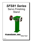
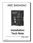
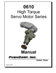
SMMCON Manual SMRCON Remote Servo Control Cabinet SMRCON Remote Control Cabinet SMMCON Manual Control Cabinet P USH C ORP, I NC. Dallas, Texas P USH C ORP, I NC. SMMCON/SMRCON Manual 1 Table of Contents 1.0 LIMITED WARRANTY.............................................................................................2 2.0 GENERAL OVERVIEW............................................................................................4 3.0 INSTALLATION........................................................................................................4 3.1 Cabinet Mounting.............................................................................................................................. 4 3.2 Electrical Connections....................................................................................................................... 5 4.0 OPERATION.............................................................................................................7 5.0 TECHNICAL SPECIFICATIONS AND SCHEMATICS.............................................9 Copyright PushCorp, Inc. 2013. All rights reserved P USH C ORP, I NC. SMMCON/SMRCON Manual 2 1.0 Limited Warranty Duration: One year from date of delivery to the original purchaser. Who gives this warranty (warrantor): PushCorp, Inc. Telephone: (972) 840-0208 Corporate Address: P. O. Box 181915 Dallas, Texas 75218 Shipping Address: 3001 W. Kingsley Rd. Garland, Texas 75041 Who receives this warranty (purchaser): The original purchaser (other than for purposes of resale) of the PushCorp, Inc. product What products are covered by this warranty: Any PushCorp, Inc. Adjustable Force Device or Adjustable Force Device accessory supplied or manufactured by the Warrantor. What is covered under this warranty: Defects in material and/or workmanship which occur within the duration of the warranty period. What is NOT covered in this warranty: A. IMPLIED WARRANTIES, INCLUDING THOSE OF MERCHANT-ABILITY AND FITNESS FOR A PARTICULAR PURPOSE ARE LIMITED TO ONE YEAR FROM THE DATE OF ORIGINAL PURCHASE. Some states do not allow limitations on how long an implied warranty lasts, so the above limitations may not apply to you. B. ANY INCIDENTAL, INDIRECT, OR CONSEQUENTIAL LOSS, DAMAGE or EXPENSE THAT MAY RESULT FROM ANY DEFECT, FAILURE, MALFUNCTION OF THE PUSHCORP, INC. PRODUCT. Some states do not allow the exclusion or limitation of incidental or consequential damages so the above limitation or exclusion may not apply to you. C. Any failure that results from an accident, purchaser's abuse, neglect, unauthorized repair or failure to operate the products in accordance with the instructions provided in the owner's manual(s) supplied with the product. Responsibilities of the Warrantor under this warranty: Repair or replace, at Warrantor's option, products or components which have failed within the duration of the warranty period. Copyright PushCorp, Inc. 2013. All rights reserved P USH C ORP, I NC. SMMCON/SMRCON Manual 3 Responsibilities of the purchaser under this warranty: A. Deliver or ship the PushCorp, Inc. product or component to PushCorp, Inc. Service Center, Dallas, TX. Freight and insurance costs, if any, must be borne by the purchaser. B. Use reasonable care in the operation and maintenance of the product as described in the owner's manual(s). When warrantor will perform repair or replacement under this warranty: Repair or replacement will be scheduled and serviced according to the normal work flow at the service center, and depending on the availability of replacement parts. Purchasers requiring quicker repair may receive such with payment of a PushCorp, Inc. predetermined expediting fee. This Limited Warranty gives you specific legal rights and you may also have other rights which vary from state to state. Copyright PushCorp, Inc. 2013. All rights reserved P USH C ORP, I NC. SMMCON/SMRCON Manual 4 2.0 General Overview The PushCorp SMMCON and SMRCON control cabinets provide a highly integrated, easy to use solution to controlling PushCorp servomotor equipment. Installation is simply a matter of mounting the cabinet and connecting 3-phase, 208 – 480VAC, electrical power. The SMRCON Remote Control Console allows servo equipment to be controlled via a remote PLC or robot controller with a minimum number of digital and analog I/O. The SMMCON Manual Control Console has front panel displays and controls so that the servomotor equipment can be easy controlled and monitored by a human operator. 3.0 Installation 3.1 Cabinet Mounting The cabinet is designed to be wall mounted outside the robot work area in a relatively clean environment. Figure 1 shows the mounting dimensions of the electrical enclosure. Figure 1. Cabinet Mounting It is the responsibility of the installer to punch holes in the enclosure for conduit and/or cord grips as required for the electrical supply power wiring and low-voltage control signals. Copyright PushCorp, Inc. 2013. All rights reserved P USH C ORP, I NC. SMMCON/SMRCON Manual 5 3.2 Electrical Connections The cabinet requires 208 - 480 VAC, 3-Phase, 50-60 Hz. power to operate. This should be supplied via conduit connection to the cabinet as shown in Figure 2. The control signal connections are made to the External Interface Blocks as shown in Figure 3. Figure 2. Electrical cable entry locations Figure 3. Console electrical panel Copyright PushCorp, Inc. 2013. All rights reserved P USH C ORP, I NC. SMMCON/SMRCON Manual 6 Figure 4. Typical External Interface Schematic The circuit diagram in Figure 4 shows an example of how the SMRCON (Remote) cabinet could be wired for operation. The SMMCON (Manual) cabinet already includes these elements on the front panel for control. All digital I/O is designed for 24 VDC control voltages. The motor rotational speed is controlled via a 0 - 10VDC analog signal applied to terminals 9 and 10. The analog input is a true floating differential signal connected directly to the servo amplifier. The circuit shown in Figure 4 is an example of how the shaft speed may be controlled with a simple panel mount linear potentiometer. If remote robot teach pendent adjustment is desired, the potentiometer would be replaced with an analog signal from a PLC or robot analog output card connected directly to Pins 9 and 10. WARNING: The differential voltage applied to terminals 9 and 10 should not exceed 10 VDC or damage will occur to the servo amplifier. Terminal 7, shown in Figure 4 provides the servo amplifier enable signal. Connecting Terminal 7 to +24VDC enables the servo amplifier and applies voltage to the servo motor. Removing voltage from terminal 7 disables the amplifier. The “DRIVE OK” output on Terminal 11 should be continuously monitored by the Enduser control system. This signal should be “ON” during normal operation. An “OFF” condition indicates a drive fault. The cause of the fault will be indicated by a flashing code on the servo drive amplifier. The end-users should contact PushCorp directly for support regarding drive amplifier faults. OPERATION SHOULD CEASE UNTIL THE FAULT CONDITION IS CORRECTED. Copyright PushCorp, Inc. 2013. All rights reserved P USH C ORP, I NC. SMMCON/SMRCON Manual 7 Each Electrical Control box includes a built-in E-Stop push button that, when pressed, immediately removes all electrical power from the motor causing it to coast to a stop. If desired, the control box can be connected to an external, dual-channel, E-Stop circuit by connecting to the STO1 and STO2 signals on Terminals 3, 4, 5, and 6 as shown. It is the responsibility of the System Integrator and/or End-user to follow all applicable electrical codes and OSHA safety standards when wiring the control cabinet. This includes the proper and judicious use of ground termination, fuses, contactors, cut-off switches, lock-out switches, and Emergency Stop circuits. PushCorp, Inc. assumes no responsibility or liability for the electrical system design and implementation of the control cabinet in the End-user application. Refer to OSHA rules and regulations, as well as the CE Machinery Regulations (IEC 204-1), when designing systems that include motors and drives to ensure that the user is protected. PushCorp will provide answers to any questions regarding the servo drive system and will be responsible for any warranty issues. NOTE: Please contact PushCorp, Inc. (Tel 1.972.840.0208) directly for any technical support. 4.0 Operation Figures 5 and 6 below show the front panel layout for the SMRCON Remote Control Cabinet and SMMCON Manual Control Cabinet respectively. The SMRCON, being designed exclusively for remote control, includes only an Main Power switch and an Emergency Stop (E-STOP) button. Figure 5. SMRCON Remote Control Cabinet Front Panel Copyright PushCorp, Inc. 2013. All rights reserved P USH C ORP, I NC. SMMCON/SMRCON Manual 8 Figure 6. SMMCON Manual Control Cabinet Front Panel The SMMCON cabinet includes additional controls and digital indicators that allow the servo equipment to be operated manually. INDICATORS LOAD – Digital percentage display of maximum rated “load” (Output Torque) at which the motor is operating. It is recommended that the long-term continuous load not exceed 70% for reliable operation in production environments. SPEED – Digital percentage display of maximum rated speed at which the motor is operating. READY – When illuminated, indicates that the servomotor is ready to operate. If not illuminated, a fault exists. The fault can be reset by disabling and then reenabling the servo system via the Enable switch. CONTROLS ENABLE – The Enable switch enables or disables output power to the servomotor. DANGER!!! THE CONSOLE ENABLE SWITCH SHOULD ONLY BE “ON” WHEN THE SERVOMOTOR POWER CABLE IS FULLY CONNECTED TO THE SERVOMOTOR. ENABLING THE SERVOMOTOR POWER WHILE DISCONNECTED COULD RESULT IN INJURY OR DEATH. SPEED – The control knob allows the speed to be set from zero to 100% of the maximum rated speed of the servomotor. The speed can be varied at any time while the servomotor is enabled or disabled. The actual measured percent speed will be displayed on the digital Speed indicator. Copyright PushCorp, Inc. 2013. All rights reserved P USH C ORP, I NC. SMMCON/SMRCON Manual 9 5.0 Technical Specifications and Schematics Supply Voltage: Max. Cont. Current: Max. Peak Current: 208 - 480 VAC, 3-Phase 30 Amps 60 Amps (2 Seconds) Specifications subject to change without notice. Copyright PushCorp, Inc. 2013. All rights reserved P USH C ORP, I NC. SMMCON/SMRCON Manual 10 Copyright PushCorp, Inc. 2013. All rights reserved P USH C ORP, I NC. SMMCON/SMRCON Manual 11 Copyright PushCorp, Inc. 2013. All rights reserved