1
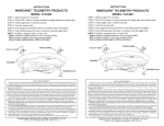
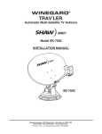
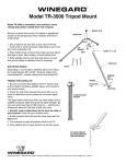
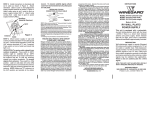
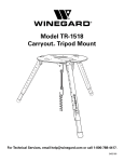
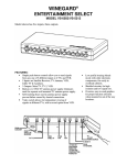
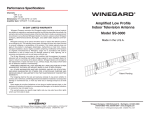
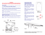
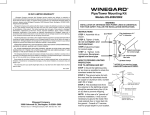
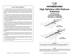
WINEGARD®
TRAV’LER
®
Automatic Multi-Satellite TV Antenna
Model SKA-733 Reflector & Bracket
INSTALLATION MANUAL
Made in the U.S.A.
Winegard Company • 3000 Kirkwood St. • Burlington, IA 52601-2000
319/754-0600 • FAX 319/754-0787 • www.winegard.com
Printed in U.S.A. © Winegard Company 2012 1/12 2452259
B. Manual:
TRAV’LER® SHAW DIRECT Reflector and Bracket Installation
!
Check to be sure that there is nothing above the TRAV’LER antenna that might
prevent it from raising. You will need at least 40” of clearance above the TRAV’LER
mount to ensure that you have room to install the reflector. Pay attention to these Pinch
Points as the antenna raises.
NOTE: Pinch Points are called out both for your safety and to protect the cables. Cables will be damaged if installed incorrectly. See pages 3-4 in this installation manual.
1. Unplug TRAV’LER Interface.
2. Remove the black plastic bolt from the back of the mount using a wrench.
3. Insert a 1/4 inch socket extension into the auxiliary drive as shown in Figure 2.
Turn auxiliary drive counter clockwise to raise the unit enough to install new reflector bracket.
!
NOTE: DO NOT USE A DRILL AS THIS WILL
DAMAGE THE TRAV’LER ELECTRONICS.
Auxiliary Drive
FIGURE 2
Coax Cable
Connections
FIGURE 1
Install the Reflector:
Raise Antenna:
There are two ways to raise the antenna, automatic or manual; each is explained below.
A. Automatic:
Steps 1-7 explain how to use the TRAV’LER Interface Box to raise the mount.
1. Press [POWER] and hold for 2 seconds to turn “ON” the TRAV’LER Interface Box. Wait until the
Interface Box finishes “connecting to antenna”.
To Raise
Unit, turn
Counterclockwise
* The TRAV’LER may enter the “Search Routine” after 10 seconds; this is normal (See NOTE Below).
2. Press [ENTER] and hold for 2 seconds or until the unit displays “Enter User Menu”. Press [SELECT] to move the asterisk to “Yes”. Press [ENTER].
3. Press [SELECT] to move the asterisk to INSTALLATION.
4. Press [ENTER]. You will be asked to provide a code to enter the Installation Menu.
1. Insert the two long screws into the top two
holes in the front of the Reflector.
2. Slide one of the wedge shaped clamps onto
each screw sticking out of the back of the Reflector.
3. Thread a nut onto each screw just enough to keep the
clamp from falling off.
4. Set the SHAW DIRECT Reflector on the Skew Plate (in Figure 3) by lining up the two anchor posts in the base of the Reflector with the two notches in the Skew Plate. The Reflector should be installed so
that the LNB Arm is at the bottom of this plate.
5. Carefully use the clamps on the back of the
Reflector to hold the Reflector in place.
FIGURE 3
Black Plastic Bolt
FIGURE 4
Skew
Skew Plate
Clamp
Notch
Anchor
Post
Anchor
Post
5. Press [ENTER] 4 times to enter code 0000.
6. Press [SELECT] to move the asterisk to RAISE ANTENNA. Press [ENTER]. Press [SELECT] to move the asterisk to Yes.
7. Press [ENTER]. The TRAV’LER mount will raise up about half way.
* NOTE: If the TRAV’LER enters the “Search Routine,” and the TRAV’LER mount raises more than 1/2 way before RAISE ANTENNA is selected (See Step 6), the TRAV’LER will hit its Upper Hard Stop and “Motor Stall” will
appear. This is Normal.
The “Motor Stall” means the TRAV’LER is all the way up and the mount cannot raise any more. There are two
easy ways to clear the “Motor Stall”.
a. Press [ENTER] the TRAV’LER antenna will return to the “Installation Menu”
OR
b. Press [POWER] the TRAV’LER antenna will stow and turn “OFF” (Restart at Step 1).
INSTALLATION
2
Note: Make sure that the thicker part of the clamp is to the
outside of the Reflector.
6. Once the top screws and clamps are in place,
install the lower screws and clamps.
7. Tighten the nuts on all four screws.
FIGURE 5
Coax Cable
Clamp
Rev. 4/09
Rev. 4/09
INSTALLATION
3
8. With the Bracket mounted securely, connect the four Coax Cables to the Mount, as shown in Figure 6.
9. Find the Cable Tie on the coax cables
that you have just connected to the mount. Place the
coax cable clamp on the cables just below this cable
tie. Carefully screw this clamp to the front of the Lift Arm
using the 5/16 inch screw provided. See Figure 5.
DO NOT over tighten this screw.
!
FIGURE 6
Coax
Connections
Be Careful not to strip out the hole for the 5/16 inch
screws when you replace the clamp holding the
coax cables to the arm. DO NOT use a power tool.
NOTE: If the cable tie is missing, install the clamp 14” from
the end of the connectors.
Calibrate the Elevation Motor:
1. Press [POWER] and hold for 2 seconds to turn “ON” the TRAV’LER Interface Box. Wait until the
Interface Box finishes “connecting to antenna”.
2. Press [ENTER] and hold for 2 seconds or until the unit displays “Enter User Menu”. Press
[SELECT] to move the asterisk to “Yes”. Press [ENTER].
3. Press [SELECT] to move the asterisk to INSTALLATION.
4. Press [ENTER]. You will be asked to provide a code to enter the Installation Menu.
5. Press [ENTER] 4 times to enter code 0000.
6. From the Installation Menu,
7. Press [SELECT] to move “ * ” to “Calibrate EL” and Press [ENTER].
8. Press [SELECT] to move “ * ” to YES.
9. Press [ENTER] to start the elevation calibration procedure. The LCD should now display
“ Calibrate EL In Progress ...”.
WINEGARD MOBILE PRODUCTS LIMITED WARRANTY
(2 YEARS PARTS; 1 YEAR LABOR)
Winegard Company warrants this product against defects in materials or workmanship for a period of two (2) years
from the date of original purchase. During year one (1) of such warranty, Winegard Company will also pay authorized labor costs to an authorized Winegard dealer to repair or replace defective products. No warranty claim will be
honored unless at the time the claim is made, Customer presents proof of purchase to an authorized Winegard dealer
(to locate the nearest authorized Winegard dealer, contact Winegard Company, 3000 Kirkwood Street, Burlington, Iowa
52601, Telephone 800-288-8094 or visit www.winegard.com). Customer must provide proof of purchase with a dated
sales receipt for the Winegard product to verify the product is under warranty. If the date of purchase cannot be verified, the warranty period shall be considered to begin thirty (30) days after the date of manufacture.
If a defect in material or workmanship is discovered, Customer may take the product to an authorized Winegard
dealer for service. Customer must provide proof of purchase to verify the product is under warranty. If the product is
brought to an authorized Winegard dealer for service prior to expiration of year one (1) of the warranty period and a
defect in material or workmanship is verified by Winegard Technical Services, Winegard Company will cover the Winegard dealer’s labor charges for warranty service. The Winegard dealer must contact Winegard Technical Services in
advance for pre-approval of the service. Approval of the service is at the sole discretion of Winegard Company.
Alternatively, Customer may ship the product prepaid to Winegard Technical Services (located at 3111 Kirkwood
Street, Burlington, Iowa 52601, Telephone 800-788-4417). Customer must return the product along with a brief description of the problem and provide Winegard Technical Services with Customer’s name, address, and phone number.
Customer must also provide proof of purchase to verify the product is under warranty. If the product is returned before
the expiration of the warranty period, Winegard Company will (at its option) either repair or replace the product.
This Limited Warranty does not apply if the product has been damaged, deteriorates, malfunctions or fails from: improper installation, misuse, abuse, neglect, accident, tampering, modification of the product as originally manufactured
by Winegard in any manner whatsoever, removing or defacing any serial number, usage not in accordance with product instructions or acts of nature such as damage caused by wind, lightning, ice or corrosive environments such as salt
spray and acid rain. This Limited Warranty also does not apply if the product becomes unable to perform its’ intended
function in any way as a result of the television signal provider making any changes in technology or service.
RETURN AUTHORIZATION POLICY
A Return Material Authorization (RMA) is required prior to returning any product to Winegard Company or Winegard
Warranty Services under this warranty policy. Please call our Technical Services Department at 800-788-4417 or send
an e-mail to [email protected] to obtain the RMA number. Please furnish the date of purchase when requesting an RMA number. Enclose the product in a prepaid package and write the RMA number in large, clear letters on
the outside of the package. To avoid confusion or misunderstanding, a shipment(s) without an RMA number(s) or an
unauthorized return(s) will be refused and returned to Customer freight collect.
WINEGARD COMPANY DOES NOT ASSUME ANY LIABILITIES FOR ANY OTHER WARRANTIES, EXPRESS OR
IMPLIED, MADE BY ANY OTHER PERSON.
ALL OTHER WARRANTIES WHETHER EXPRESS, IMPLIED OR STATUTORY INCLUDING WARRANTIES OF FITNESS FOR A PARTICULAR PURPOSE AND MERCHANTABILITY ARE LIMITED TO THE TWO YEAR PERIOD OF
THIS WARRANTY.
In states that do not allow limitations on implied warranties, or the exclusion of limitation of incidental or consequential
damages, the above limitations or exclusions do not apply.
Some states do not allow limitations on how long an implied warranty lasts, or the exclusion of limitation of incidental
or consequential damages, so the above limitations or exclusions may not apply to you.
This warranty gives Customer specific legal rights. Customer may also have other rights that may vary from state to
state.
SATELLITE RECEIVER WARRANTY
See manufacturer’s limited warranty policy.
10. After a few moments the IDU LCD will display
“On EL Hard Stop?
Yes
*No”.
WS-MOBWARREV2
Rev. 1/10
Visually examine the antenna to verify that the antenna is against the Hard Stop. The antenna will be pointing as
far up as it can go, this is the Hard Stop.
11. Press [SELECT] once to move asterisk to “Yes” if antenna is on the Hard Stop.
12. Press [ENTER] and the LCD will display “Calibrate EL Success”.
13. Press and Hold [POWER] for 2 seconds to to stow the antenna.
INSTALLATION
4
!
INSTALLATION
DO NOT paint this antenna!
Painting the TRAV’LER antenna
will void your warranty.
5
Winegard Company • 3000 Kirkwood Street • Burlington, IA 52601 • 319/754-0600 Fax 319/754-0787 • www.winegard.com
Printed in U.S.A. © 2012 Winegard Company 1/12 2452259
6