1
Agilent 1260 Infinity
Preparative Pump
User Manual
Notices
© Agilent Technologies, Inc. 2006, 2007-2011
No part of this manual may be reproduced
in any form or by any means (including electronic storage and retrieval or translation
into a foreign language) without prior agreement and written consent from Agilent
Technologies, Inc. as governed by United
States and international copyright laws.
Manual Part Number
G1361-90012
Edition
02/2011
Printed in Germany
Agilent Technologies
Hewlett-Packard-Strasse 8
76337 Waldbronn
This product may be used as a
com-ponent of an in vitro diagnostic
sys-tem if the system is registered
with the appropriate authorities and
com-plies with the relevant regula-tions. Otherwise, it is intended
only for gen-eral laboratory use.
LVggVcin
The material contained in this document is provided “as is,” and is subject to being changed, without notice,
in future editions. Further, to the maximum extent permitted by applicable
law, Agilent disclaims all warranties,
either express or implied, with regard
to this manual and any information
contained herein, including but not
limited to the implied warranties of
merchantability and fitness for a particular purpose. Agilent shall not be
liable for errors or for incidental or
consequential damages in connection
with the furnishing, use, or performance of this document or of any
information contained herein. Should
Agilent and the user have a separate
written agreement with warranty
terms covering the material in this
document that conflict with these
terms, the warranty terms in the separate agreement shall control.
terms, and non-DOD Departments and
Agencies of the U.S. Government will
receive no greater than Restricted Rights as
defined in FAR 52.227-19(c)(1-2) (June
1987). U.S. Government users will receive
no greater than Limited Rights as defined in
FAR 52.227-14 (June 1987) or DFAR
252.227-7015 (b)(2) (November 1995), as
applicable in any technical data.
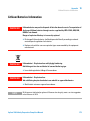
Safety Notices
CAUTION
A CAUTION notice denotes a
hazard. It calls attention to an
operating procedure, practice, or
the like that, if not correctly performed or adhered to, could
result in damage to the product
or loss of important data. Do not
proceed beyond a CAUTION
notice until the indicated conditions are fully understood and
met.
Technology Licenses
The hardware and/or software described in
this document are furnished under a license
and may be used or copied only in accordance with the terms of such license.
Restricted Rights Legend
If software is for use in the performance of a
U.S. Government prime contract or subcontract, Software is delivered and licensed as
“Commercial computer software” as
defined in DFAR 252.227-7014 (June 1995),
or as a “commercial item” as defined in FAR
2.101(a) or as “Restricted computer software” as defined in FAR 52.227-19 (June
1987) or any equivalent agency regulation
or contract clause. Use, duplication or disclosure of Software is subject to Agilent
Technologies’ standard commercial license
WA R N I N G
A WARNING notice denotes a
hazard. It calls attention to an
operating procedure, practice,
or the like that, if not correctly
performed or adhered to, could
result in personal injury or
death. Do not proceed beyond a
WARNING notice until the indicated conditions are fully understood and met.
Agilent 1260 Infinity Preparative Pump User Manual
Contents
Contents
1 Introduction to the Preparative Pump
Introduction to the Preparative Pump
Instrument Layout 12
The Electronics 13
Electrical Connections 14
Interfaces 16
2 Site Requirements and Specifications
7
8
23
Site Requirements 24
Physical Specifications 27
Performance Specifications 28
3 Installing the Pump
29
Unpacking the Preparative Pump 30
Optimizing the Stack Configuration 34
Installing the Preparative Pump 36
Connecting Modules and Control Software 40
Flow Connections for a Single (Isocratic) Preparative Pump 42
Flow Connections for a Dual (Binary Gradient) Preparative Pump
Get the System Ready for the First Analysis 49
4 Using the Preparative Pump
51
Hints for Successful Use of the Preparative Pump
Solvent Information 53
Prevent Blocking of Solvent Filters 54
Algae Growth in HPLC Systems 55
Setting Up the Pump 57
Agilent 1260 Infinity Preparative Pump User Manual
45
52
3
Contents
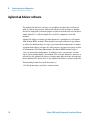
5 Optimizing Performance
65
How to Configure the Seal Wash Function 66
How to Optimize the Compressibility Compensation Setting
6 Troubleshooting and Diagnostics
69
Agilent Lab Advisor software 70
Overview of the Pump’s Indicators and Test Functions
Status Indicators 72
User Interfaces 74
Error Messages 75
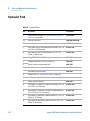
Pressure Test 94
Leak Test 98
EMPV Cleaning 103
7 Maintenance
67
71
107
Introduction to Maintenance and Repair 108
Overview of Maintenance and Repair 112
Simple Repairs 114
8 Parts and Materials for Maintenance
133
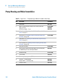
Pump Housing and Main Assemblies 134
Pump-Head Assembly 138
Solvent Cabinet and Solvent Inlet Parts 140
Hydraulic Path 142
Preparative Pump Basis Kit 145
Preparative Pump Gradient Kit 147
9 Configuring the Preparative Pump
Preparative Pump Main Board (PPM)
Optional Interface Boards 155
Interfaces 159
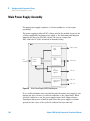
Main Power Supply Assembly 164
4
149
150
Agilent 1260 Infinity Preparative Pump User Manual
Contents
10 Appendix
167
General Safety Information 168
The Waste Electrical and Electronic Equipment (WEEE) Directive
(2002/96/EC) 172
Lithium Batteries Information 173
Radio Interference 174
Sound Emission 175
Solvent Information 176
Agilent Technologies on Internet 178
Agilent 1260 Infinity Preparative Pump User Manual
5
Contents
6
Agilent 1260 Infinity Preparative Pump User Manual
Agilent 1260 Infinity Preparative Pump User Manual
1
Introduction to the Preparative Pump
Introduction to the Preparative Pump 8
Hydraulic Path Overview 9
How Does Compressibility Compensation Work?
Early Maintenance Feedback (EMF) 11
Instrument Layout
The Electronics
12
13
Electrical Connections
Interfaces
10
14
16
Agilent Technologies
7
1
Introduction to the Preparative Pump
Introduction to the Preparative Pump
Introduction to the Preparative Pump
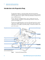
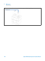
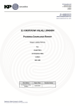
The preparative pump is a cam driven pump, with fixed stroke and two
parallel pistons, each with (identical ball and seat) inlet and outlet valve. Each
of the two pump pistons is capable of delivering a maximum of 50 ml/min flow
at up to 400 bar pressure.
The two cams have overlapping delivery cycles. Compression losses are
calculated and smooth delivery is ensured through variation of the motor
speed over the pump cycle.
The pistons are guided through two seals each. The gap between those seals is
connected to capillary fittings, this way seal wash is not only an option, but
integral part of every pump. A peristaltic pump, to automate seal wash, is also
part of the system.
EjbeYg^kZ
EdlZghjeean
EEBWdVgY
;^ii^c\hhZValVh]
;Vc
DjiaZikVakZh
Ejbe]ZVY
>caZikVakZh
:aZXigdbV\cZi^X
ejg\ZkVakZ
AZV`hZchdg
HZValVh]ejbe
Bjai^"6hhZbWanl^i][^aiZghVcY
egZhhjgZhZchdgVii]ZgZVg
Figure 1
8
Overview of the Preparative Pump
Agilent 1260 Infinity Preparative Pump User Manual
Introduction to the Preparative Pump
Introduction to the Preparative Pump
1
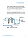
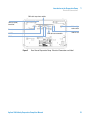
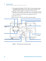
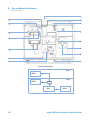
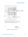
Hydraulic Path Overview
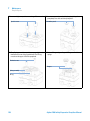
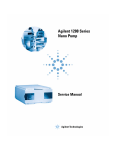
The pump flow leaving the pump head passes through the multi-assembly,
which combines the flow of the two pistons, filters the solvent and contains a
pressure sensor to monitor system pressure. No hydraulic damper is included
in the system. This makes very fast gradients possible. From the
multi-assembly the flow is routed to the purge valve and from there either
directly into waste or on to the next module (normally injection valve or
sampling device).
Gradients are formed with two combined pumps, as high pressure gradients.
The combined flow, is flowing through a passive mixer, to smooth composition.
With its high pressure mixing principle gradient systems and the usually high
flow rates, no degassing of solvents is necessary.
To avoid outgassing in the detector cell a back pressure regulating device is
recommended for applications that demand it.
>caZikVakZ&
;gdbhdakZciWdiiaZ
;gdbEjbe7!dcan
^cW^cVgn\gVY^ZcihnhiZb
>caZikVakZ'
DjiaZi
kVakZ&
DjiaZi
kVakZ'
;ZbVaZI!dcan
^cW^cVgn
\gVY^ZcihnhiZb
B^mZg!dcan^c
W^cVgn\gVY^ZcihnhiZb
HZVah'm'
:BEK
E^hidc&
Bjai^"6hhZbWan
l^i]'[^aiZghVcY
egZhhjgZhZchdg
IdLVhiZ
E^hidc'
Figure 2
Schematics of the Preparative Pump
Agilent 1260 Infinity Preparative Pump User Manual
9
1
Introduction to the Preparative Pump
Introduction to the Preparative Pump
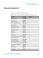
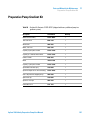
Table 1
Preparative Pump Details
Materials in contact with mobile phase
Bottle head assembly
glass frits, PTFE compounds, PEEK
Pump head
SST, sapphire
Inlet/Outlet Valves
SST, sapphire, ruby, PEEK
EMPV
SST, ruby, sapphire, PEEK
Filter Cup
SST
Filter Plate
SST, PEEK
Pressure Sensor
SST, PEEK
Capillaries
SST
For pump specifications, see “Site Requirements” on page 24.
How Does Compressibility Compensation Work?
The compressibility of the solvents in use will affect retention-time stability
when the back pressure in the system changes (for example, ageing of
column). In order to minimize this effect, the pump provides a compressibility
compensation feature which optimizes the flow stability according to the
solvent type. The compressibility compensation is set to a default value and
can be changed through the user interface.
Without a compressibility compensation the following will happen during a
stroke of the first piston. The pressure in the piston chamber increases and
the volume in the chamber will be compressed depending on backpressure and
solvent type. The volume displaced into the system will be reduced by the
compressed volume.
When a compressibility compensation value for the pump head is set, the
pump processor calculates a compensation volume that depends on the
system pressure and the selected compressibility value. The pump has a fixed
stroke. To compensate for compressibility losses, the speed of the piston
movement has to be varied during the different parts of each stroke.
10
Agilent 1260 Infinity Preparative Pump User Manual
Introduction to the Preparative Pump
Introduction to the Preparative Pump
1
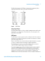
Early Maintenance Feedback (EMF)
The early maintenance feedback (EMF) feature monitors the usage of specific
components in the instrument, and provides feedback when the user-settable
limits have been exceeded. The visual feedback in the user interface provides
an indication that maintenance procedures should be scheduled.
For details on EMF counters and how to use them, see Agilent Lab Advisor.
Agilent 1260 Infinity Preparative Pump User Manual
11
1
Introduction to the Preparative Pump
Instrument Layout
Instrument Layout
The industrial design of the module incorporates several innovative features.
It uses Agilent’s E-PAC concept for the packaging of electronics and
mechanical assemblies. This concept is based upon the use of expanded
polypropylene (EPP) layers foam plastic spacers in which the mechanical and
electronic boards components of the module are placed. This pack is then
housed in a metal inner cabinet which is enclosed by a plastic external
cabinet. The advantages of this packaging technology are:
• virtual elimination of fixing screws, bolts or ties, reducing the number of
components and increasing the speed of assembly/disassembly,
• the plastic layers have air channels molded into them so that cooling air can
be guided exactly to the required locations,
• the plastic layers help cushion the electronic and mechanical parts from
physical shock, and
• the metal inner cabinet shields the internal electronics from
electromagnetic interference and also helps to reduce or eliminate radio
frequency emissions from the instrument itself.
12
Agilent 1260 Infinity Preparative Pump User Manual
1
Introduction to the Preparative Pump
The Electronics
The Electronics
The electronics are comprised of four main components:
• The preparative pump main board (PPM), see “Preparative Pump Main
Board (PPM)” on page 150.
• Power supply, see “Main Power Supply Assembly” on page 164.
Optional:
• Interface board (BCD/external contacts), see “BCD / External Contact
Board” on page 155
• LAN Communication Card, see “LAN Communication Interface Board” on
page 157.
Main Board
The board controls all information and activities of all assemblies within the
module. The operator enters parameters, changes modes and controls the
module through interfaces (CAN, GPIB or RS-232C), connected to the
user-interfaces.
Main Power Supply Assembly
The main power supply comprises a closed assembly (no on-site repair
possibility). The power supply provides all DC voltages used in the module
except for the voltages supplied by the lamp power supply to the deuterium
and tungsten lamps in the detectors.
The line voltage can vary in a range from 100 – 240 volts AC ± 10% and needs
no manual setting.
Optional Interface Boards
The Agilent 1260 Infinity modules have one optional board slot that allows to
add an interface board to the modules. Optional interface boards for the
Agilent 1260 Infinity Series are:
• BCD Board
• LAN Communication Card
Agilent 1260 Infinity Preparative Pump User Manual
13
1
Introduction to the Preparative Pump
Electrical Connections
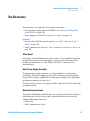
Electrical Connections
• The GPIB connector is used to connect the module with a computer. The
address and control switch module next to the GPIB connector determines
the GPIB address of your module. The switches are preset to a default
address and is recognized once after power is switched ON.
• The CAN bus is a serial bus with high speed data transfer. The two
connectors for the CAN bus are used for internal Agilent 1260 Infinity
module data transfer and synchronization.
• One analog output provides signals for integrators or data handling
systems.
• The interface board slot is used for external contacts and BCD bottle
number output or LAN connections.
• The REMOTE connector may be used in combination with other analytical
instruments from Agilent Technologies if you want to use features such as
start, stop, common shut down, prepare, and so on.
• With the appropriate software, the RS-232C connector may be used to
control the module from a computer through a RS-232C connection. This
connector is activated and can be configured with the configuration switch.
See your software documentation for further information.
• The power input socket accepts a line voltage of 100 – 240 volts AC ± 10%
with a line frequency of 50 or 60 Hz. Maximum power consumption is
220 VA. There is no voltage selector on your module because the power
supply has wide-ranging capability. There are no externally accessible
fuses, because automatic electronic fuses are implemented in the power
supply. The security lever at the power input socket prevents the module
cover from being taken off when line power is still connected.
NOTE
14
Never use cables other than the ones supplied by Agilent Technologies to ensure proper
functionality and compliance with safety or EMC regulations.
Agilent 1260 Infinity Preparative Pump User Manual
Introduction to the Preparative Pump
Electrical Connections
1
86CXVWaZidegZk^djhbdYjaZ
>ciZg[VXZ789
WdVgYhadi
-"W^iXdc[^\j"
gVi^dchl^iX]
GZbdiZ
86CXVWaZidcZmibdYjaZ
GH'('8
86C"98"dji
86C"Wjh
Figure 3
Rear View of Preparative Pump - Electrical Connections and Label
Agilent 1260 Infinity Preparative Pump User Manual
15
1
Introduction to the Preparative Pump
Interfaces
Interfaces
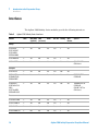
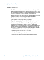
The Agilent 1200 Infinity Series modules provide the following interfaces:
Table 2
Agilent 1200 Infinity Series Interfaces
Module
CAN
LAN/BCD LAN
GPIB
(optional) (on-board)
RS-232
Analog
APG
Remote
Special
G1310A ISO
G1311A QUAT
G1312A BIN
G2226A NANO
2
Yes
No
Yes
Yes
1
Yes
G1312B BIN SL
2
Yes
No
Yes
Yes
1
Yes
G1361A PREP
2
Yes
No
No
Yes
No
Yes
G1313A STD
2
Yes
No
Yes
Yes
No
Yes
G1329A STD
G1329B STD SL
G2260A PREP
2
Yes
No
Yes
Yes
No
Yes
THERMOSTAT for
G1330A/B
G1364A FRC
G1367A/B/C/D
WPS
G1377A µWPS
G2258A D-LOOP
2
Yes
No
Yes
Yes
No
Yes
THERMOSTAT for
G1330A/B
CAN-DC- OUT for
CAN slaves
G1314A/B VWD
2
Yes
No
Yes
Yes
1
Yes
G1314C VWD SL
2
Yes
No
No
Yes
1
Yes
G1314D VWD
2
No
Yes
No
Yes
1
Yes
G1314E VWD SL+
2
No
Yes
No
Yes
1
Yes
Pumps
CAN-DC- OUT for
CAN slaves
Samplers
Detectors
16
Agilent 1260 Infinity Preparative Pump User Manual
1
Introduction to the Preparative Pump
Interfaces
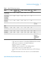
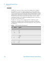
Table 2
Agilent 1200 Infinity Series Interfaces
Module
CAN
LAN/BCD LAN
GPIB
(optional) (on-board)
RS-232
Analog
APG
Remote
Special
G1315A/B DAD
G1365A/B MWD
2
Yes
No
Yes
Yes
2
Yes
G1315C DAD SL
G1365C MWD SL
G1315D DAD
G1365D MWD
2
No
Yes
No
Yes
2
Yes
G1321A FLD
G1362A RID
2
Yes
No
Yes
Yes
1
Yes
G4280A ELSD
No
No
NO
No
Yes
Yes
Yes
G1316A TCC
No
No
No
A
Yes
No
Yes
G1316B TCC SL
No
No
No
A
Yes
No
Yes
G1322A DEG
No
No
No
No
No
No
Yes
AUX
G1379A DEG
No
No
No
No
Yes
No
No
AUX
G4240A CHIP CUBE
2
Yes
No
No
Yes
No
Yes
CAN-DC- OUT for
CAN slaves
THERMOSTAT for
G1330A/B (NOT
USED
EXT Contact
AUTOZERO
Others
• CAN connectors as interface to other Agilent 1200 Infinity Series modules,
• GPIB connector as interface to the Agilent ChemStation,
• RS-232C as interface to a computer,
• REMOTE connector as interface to other Agilent products,
• analog output connector(s) for signal output, and
• interface slot for specific interfacing (external contacts, BCD, LAN and so
on).
For identification and location of the connectors, see the module manual.
Agilent 1260 Infinity Preparative Pump User Manual
17
1
Introduction to the Preparative Pump
Interfaces
NOTE
Never use cables other than the ones supplied by Agilent Technologies to ensure proper
functionality and compliance with safety or EMC regulations.
CAN
The CAN is inter-module communication interface. It is a 2-wire serial bus
system supporting high speed data communication and real-time requirement.
NOTE
If a Agilent 1260 Infinity detector (DAD/MWD/FLD/VWD/RID) is in the system, the LAN
should be connected to the DAD/MWD/FLD/VWD/RID (due to higher data load). If no
Agilent detector is part of the system, the LAN interface should be installed in the pump or
autosampler.
LAN
The 1200 Infinity modules have either an interface slot for an LAN card (e.g.
Agilent G1369A LAN Interface) or they have an on-board LAN interface (e.g.
detectors G1315C/D DAD and G1365C/D MWD). This interface allows the
control of the module/system via a connected PC with the appropriate control
software (e.g. Agilent ChemStation).
GPIB
This interface is not available in all modules and may be removed from the
modules in future.
The GPIB connector is used to connect the module with a computer. The
address and control switches next to the GPIB connector determine the GPIB
address of your module. The switches are preset to a default address and
recognized by the operating software from Agilent Technologies.
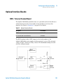
RS-232C (Serial)
The RS-232C connector is used to control the module from a computer
through RS-232C connection, using the appropriate software. This connector
can be configured with the configuration switch module next to the GPIB
connector.
18
Agilent 1260 Infinity Preparative Pump User Manual
1
Introduction to the Preparative Pump
Interfaces
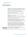
The RS-232C is designed as DCE (data communication equipment) with a
9-pin male SUB-D type connector. The pins are defined as:
>chigjbZci
BVaZ
Figure 4
E8
;ZbVaZ
;ZbVaZ BVaZ
RS-232 Cable
Analog Signal Output
The analog signal output (e.g. detector signal or pump pressure signal) can be
distributed to a recording device. For details refer to the description of the
main board of the module.
APG Remote
The APG Remote connector may be used in combination with other analytical
instruments from Agilent Technologies if you want to use features as common
shut down, prepare, and so on.
Remote control allows easy connection between single instruments or systems
to ensure coordinated analysis with simple coupling requirements.
The subminiature D connector is used. The module provides one remote
connector which is inputs/outputs (wired-or technique).
To provide maximum safety within a distributed analysis system, one line is
dedicated to SHUT DOWN the system’s critical parts in case any module
detects a serious problem. To detect whether all participating modules are
switched on or properly powered, one line is defined to summarize the
POWER ON state of all connected modules. Control of analysis is maintained
Agilent 1260 Infinity Preparative Pump User Manual
19
1
Introduction to the Preparative Pump
Interfaces
by signal readiness READY for next analysis, followed by START of run and
optional STOP of run triggered on the respective lines. In addition PREPARE
and START REQUEST may be issued. The signal level are defined as:
• standard TTL levels (0 V is logic true, + 5 V is false)
• fan-out is 10,
• input load is 2.2 kOhm against + 5 V, and
• output are open collector type, inputs/outputs (wired-or technique).
NOTE
All common TTL circuits operate with a 5 volt power supply. A TTL signal is defined as
"low" or L when between 0 V and 0.8 V and "high" or H when between 2.0 V and 5 V (with
respect to the ground terminal).
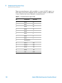
Table 3
Remote Signal Distribution
Pin
Signal
Description
1
DGND
Digital ground
2
PREPARE
(L) Request to prepare for analysis (for example, calibration, detector
lamp on). Receiver is any module performing pre-analysis activities.
3
START
(L) Request to start run / timetable. Receiver is any module
performing run-time controlled activities.
4
SHUT DOWN
(L) System has serious problem (for example, leak: stops pump).
Receiver is any module capable to reduce safety risk.
5
20
Not used
6
POWER ON
(H) All modules connected to system are switched on. Receiver is any
module relying on operation of others.
7
READY
(H) System is ready for next analysis. Receiver is any sequence
controller.
8
STOP
(L) Request to reach system ready state as soon as possible (for
example, stop run, abort or finish and stop injection). Receiver is any
module performing run-time controlled activities.
9
START REQUEST
(L) Request to start injection cycle (for example, by start key on any
module). Receiver is the autosampler.
Agilent 1260 Infinity Preparative Pump User Manual
Introduction to the Preparative Pump
Interfaces
1
Special Interfaces
Some 1260 Infinity modules have module specific interfaces/connectors. They
are described in the module documentation.
Agilent 1260 Infinity Preparative Pump User Manual
21
1
22
Introduction to the Preparative Pump
Interfaces
Agilent 1260 Infinity Preparative Pump User Manual
Agilent 1260 Infinity Preparative Pump User Manual
2
Site Requirements and Specifications
Site Requirements 24
Power Consideration
Power Cords 25
Bench Space 26
Environment 26
Physical Specifications
24
27
Performance Specifications
28
Agilent Technologies
23
2
Site Requirements and Specifications
Site Requirements
Site Requirements
A suitable environment is important to ensure optimum performance of the
instrument.
Power Consideration
The module power supply has wideranging capability (see Table 4 on page 27).
It accepts any line voltage in the range described in the above mentioned table.
Consequently there is no voltage selector in the rear of the module. There are
also no externally accessible fuses, because automatic electronic fuses are
implemented in the power supply.
WA R N I N G
Incorrect line voltage at the instrument
Shock hazard or damage of your instrumentation can result, if the devices are
connected to a line voltage higher than specified.
➔ Connect your instrument to the specified line voltage.
WA R N I N G
Module is partially energized when switched off, as long as the power cord is
plugged in.
Repair work at the module can lead to personal injuries, e.g. shock hazard, when the
cover is opened and the module is connected to power.
➔ Remove the power cable from the instrument before opening the cover.
➔ Do not connect the power cable to the Instrument while the covers are removed.
24
Agilent 1260 Infinity Preparative Pump User Manual
2
Site Requirements and Specifications
Site Requirements
CAUTION
Unaccessable power plug.
In case of emergency it must be possible to disconnect the instrument from the power
line at any time.
➔ Make sure the power connector of the instrument can be easily reached and
unplugged.
➔ Provide sufficient space behind the power socket of the instrument to unplug the
cable.
Power Cords
Different power cords are offered as options with the module. The female end
of all power cords is identical. It plugs into the power-input socket at the rear
of the module. The male end of each power cord is different and designed to
match the wall socket of a particular country or region.
WA R N I N G
The absence of ground connection and the use of an unspecified power cord can
lead to electric shock or short circuit.
Electric Shock
➔ Never operate your instrumentation from a power outlet that has no ground
connection.
➔ Never use a power cord other than the Agilent Technologies power cord designed
for your region.
WA R N I N G
Use of unsupplied cables
Using cables not supplied by Agilent Technologies can lead to damage of the
electronic components or personal injury.
➔ Never use cables other than the ones supplied by Agilent Technologies to ensure
proper functionality and compliance with safety or EMC regulations.
Agilent 1260 Infinity Preparative Pump User Manual
25
2
Site Requirements and Specifications
Site Requirements
Bench Space
The module dimensions and weight (see Table 4 on page 27) allow to place the
module on almost any laboratory bench. It needs an additional 2.5 cm
(1.0 inches) of space on either side and approximately 8 cm (3.1 inches) in the
rear for the circulation of air and electric connections.
If the bench should carry a complete Agilent 1260 Infinity system, make sure
that the bench is designed to carry the weight of all the modules.
NOTE
The module should be operated in a horizontal position!
For a complete system including multiple pumps, it is recommended to position the
modules in two or more stacks.
Environment
Your module will work within specifications at ambient temperatures and
relative humidity as described in Table 4 on page 27.
CAUTION
Condensation within the module
Condensation will damage the system electronics.
➔ Do not store, ship or use your module under conditions where temperature
fluctuations could cause condensation within the module.
➔ If your module was shipped in cold weather, leave it in its box and allow it to warm
slowly to room temperature to avoid condensation.
26
Agilent 1260 Infinity Preparative Pump User Manual
Site Requirements and Specifications
Physical Specifications
2
Physical Specifications
Table 4
Physical Specifications
Type
Specification
Weight
15.0 kg (34 lbs)
Dimensions
(width × depth × height)
200 x 345 x 440 mm (8 x 13.5 x 18
inches)
Line voltage
100 – 240 VAC, ± 10%
Line frequency
50 or 60 Hz, ± 5%
Power consumption
250 VA / 210 W / 717 BTU
Ambient operating
temperature
4–40 °C (41–104 °F)
Ambient non-operating
temperature
-40–70 °C (-4–158 °F)
Humidity
< 95%, at 25–40 °C (77–104 °F)
Operating Altitude
Up to 2000 m (6500 ft)
Non-operating altitude
Up to 4600 m (14950 ft)
For storing the module
Safety standards: IEC, CSA,
UL
Installation Category II, Pollution
Degree 2
For indoor use only.
Agilent 1260 Infinity Preparative Pump User Manual
Comments
Wide-ranging capability
Maximum
Non-condensing
27
2
Site Requirements and Specifications
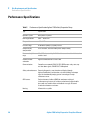
Performance Specifications
Performance Specifications
Table 5
Performance Specification Agilent 1260 Infinity Preparative Pump
Type
Specification
Hydraulic system
Dual pistons in parallel
flow rangeSettable
0.001 – 100 ml/min
Flow precision
< 0.5 % RSD
Pressure range
20 to 400 bar (5880 psi) system pressure
Compressibility
compensation
User-selectable, based on mobile phase compressibility
Recommended pH
range
1.0 – 12.5, solvents with pH < 2.3 should not contain acids which attack
stainless steel.
Control and data
evaluation
Agilent ChemStation for LC and LC/MS
Communications
Controller-area network (CAN), RS-232, APG Remote: ready, start, stop
and shut-down signals, CAN-DC OUT, LAN optional
Safety and maintenance Extensive diagnostics, error detection and display (through
Agilent ChemStation), leak detection, safe leak handling, leak output
signal for shutdown of pumping system. Low voltages in major
maintenance areas.
28
GLP features
Early maintenance feedback (EMF) for continuous tracking of
instrument usage in terms of seal wear and volume of pumped mobile
phase with user-settable limits and feedback messages. Electronic
records of maintenance and errors.
Housing
All materials recyclable.
Agilent 1260 Infinity Preparative Pump User Manual
Agilent 1260 Infinity Preparative Pump User Manual
3
Installing the Pump
Unpacking the Preparative Pump
Damaged Packaging 30
Delivery Checklist 30
Basic Kit Contents 32
Gradient Kit Contents 33
30
Optimizing the Stack Configuration
Preparative System 34
Installing the Preparative Pump
34
36
Connecting Modules and Control Software 40
Connecting Agilent 1260 Infinity modules 40
Connecting control software control module 41
Flow Connections for a Single (Isocratic) Preparative Pump
42
Flow Connections for a Dual (Binary Gradient) Preparative Pump
Get the System Ready for the First Analysis 49
Priming your preparative LC system with the pump
Agilent Technologies
45
49
29
3
Installing the Pump
Unpacking the Preparative Pump
Unpacking the Preparative Pump
Damaged Packaging
Upon receipt of your quaternary pump, inspect the shipping containers for
any signs of damage. If the containers or cushioning material are damaged,
save them until the contents have been checked for completeness and the
quaternary pump has been mechanically and electrically checked. If the
shipping container or cushioning material is damaged, notify the carrier and
save the shipping material for the carrier’s inspection.
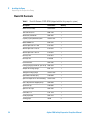
Delivery Checklist
Ensure all parts and materials have been delivered with the preparative pump.
The delivery checklist is shown in Table 6 on page 31 till Table 9 on page 33.
To aid in parts identification, please see “Parts and Materials for
Maintenance” on page 133. There are two different kits that can possibly be
delivered with the pump:
1 A Basis kit (G1361-68708) is delivered with every isocratic configuration or
if the pump is the first pump in a system (isocratic configuration, order
No. G1361A).
2 A Gradient kit (G1361-68707) is delivered with every additional pump that
is added to a system’s first pump (gradient configuration, order
No. G1391A).
Please report missing or damaged parts to your local Agilent Technologies
sales and service office.
30
Agilent 1260 Infinity Preparative Pump User Manual
Installing the Pump
Unpacking the Preparative Pump
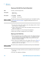
Table 6
First Preparative Pump (G1361A) Delivery Checklist
Description
Quantity
Preparative Pump
1
Corrugated waste tubing
1
Power cable (local)
1
Service Manual
1
Solvent cabinet
1
Basis kit (see Table 8 on
page 32)
1 with every FIRST (G1361A) pump of a system, only!
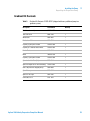
Table 7
3
Gradient Preparative Pump (G1391A) Delivery Checklist
Description
Quantity
Preparative Pump
1
Corrugated waste tubing
1
Power cable (local)
1
Gradient kit (see Table 9 on
page 33)
1 with very ADD-ON (G1391A) pump of a system!
Agilent 1260 Infinity Preparative Pump User Manual
31
3
Installing the Pump
Unpacking the Preparative Pump
Basic Kit Contents
Table 8
32
Basis Kit Contents G1361-68708 (shipped with the first pump of a system)
Description
Part Number
Quantity
Bottle head assembly
G1361-60022
1
Tube seal wash, 2 m
0890-1764
1
Waste tube, reorder No.
5042-2461
1
Capillary 3, pump outlet to system
G1361-67302
1
Bottle AMBER 2.0 l
9301-6341
1
Wrench open end 14-17 mm
8710-2435
1
Wrench open end 1/4-5/16"
8710-0510
2
Wrench open end 7/16-3/8”
8710-0972
1
Hex key 3 mm
8710-2411
1
Hex key 4 mm
87102392
1
Pair of tweezers
5022-2195
1
Priming Syringe (re-order no., pck. of 10) 5062-8534
1
Adapter for Priming Syringe
9301-1337
1
Tubing for Priming Syringe
G1361-87300
1
Spare bottle inlet filter (frit)
3150-0944
1
Spare frit adapter for 4.7 mm OD tubing
G1361-23205
1
Glass stop valve for stopped pumps
5042-6464
1
Spare filter cup
3150-0942
1
Spare SST frit 2 µm
5022-2192
1
CAN cable, 1 m
5181-1519
1
Union preparative
5022-2133
1
Sanding paper
no PN
2
Agilent 1260 Infinity Preparative Pump User Manual
Installing the Pump
Unpacking the Preparative Pump
3
Gradient Kit Contents
Table 9
Gradient Kit Contents G1361-68707 (shipped with every additional pump in a
gradient system)
Description
Part Number
Quantity
Bottle head assembly
G1361-60022
1
Tube seal wash
0890-1764
1
Waste tube
5042-2461
1
Bottle, clear 2.0 l
9301-6342
1
Capillary 5, pump A to T-union
G1361-67304
1
Capillary 6, T-union to inlet of mixer
G1361-67305
1
Female-T-union
0100-1016
1
Mixer
79835-87330
1
Capillary 7, pump B to T-union
G1361-67306
1
Spare bottle inlet filter (frit)
3150-0944
1
Spare frit adapter for 4.7 mm OD tubing
G1361-23205
1
Glass stop valve for stopped pumps
5042-6464
1
Spare filter cup
3150-0942
1
Spare SST frit 2 µm
5022-2192
1
CAN cable, 0.5 m
5181-1516
1
Agilent 1260 Infinity Preparative Pump User Manual
33
3
Installing the Pump
Optimizing the Stack Configuration
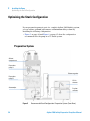
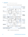
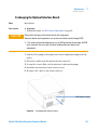
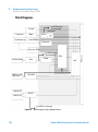
Optimizing the Stack Configuration
If your preparative pump is part of a complete Agilent 1260 Infinity system,
you can ensure optimum performance and minimum delay volume by
installing the following configuration.
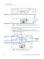
• Figure 5 on page 34 and Figure 6 on page 35 show the configuration
recommended for the pump in a UV based system.
Preparative System
HdakZci
XdbeVgibZci
EgZeVgVi^kZ
ejbe6
8dajbcdg\Vc^oZg
EgZeVgVi^kZ
ejbe7
JK"k^h
YZiZXidg
6jidhVbeaZg
;gVXi^dc
XdaaZXidg
Figure 5
34
Recommended Stack Configuration -Preparative System (Front View)
Agilent 1260 Infinity Preparative Pump User Manual
3
Installing the Pump
Optimizing the Stack Configuration
For information about connecting an LC-MSD or a None-1260 Infinity detector to the
system, please refer to the “User’s Guide for Purification / High Throughput System”, PN
G2262-90010 or to the “Installation Note for the Mass Based Fraction Collection Kit”.
NOTE
HdakZci
8dbeVgibZci
EgZeVgVi^kZ
Ejbe6
8dajbcDg\Vc^oZg
<E>7dgA6C
id8]ZbHiVi^dc
EgZeVgVi^kZ
Ejbe7
86C7jh
8VWaZ
JK"K^h
9ZiZXidg
6jidhVbeaZg
;gVXi^dc
8daaZXidg
Figure 6
NOTE
Recommended Stack Configuration - Preparative System (Rear View)
If a G1330B ALS thermostat is part of the system it must always be installed underneath
the Autosampler.
Agilent 1260 Infinity Preparative Pump User Manual
35
3
Installing the Pump
Installing the Preparative Pump
Installing the Preparative Pump
Parts required
#
Part number
Description
1
G1361A
Pump
1
Power cord, for other cables see text below and Cable Overview in the Service
Manual
1
Control Software (ChemStation, EZChrom, OpenLab, etc.) and/or
G4208A or
G1323B
Preparations
WA R N I N G
•
•
•
a handheld controller (Instant Pilot )
Locate bench space.
Provide power connections.
Unpack the pump.
Instrument is partially energized when switched off
The power supply still uses some power, even if the power switch on the front panel
is turned off.
➔ To disconnect the module from line, unplug the power cord.
WA R N I N G
Use of unsupplied cables
Using cables not supplied by Agilent Technologies can lead to damage of the
electronic components or personal injury.
➔ Never use cables other than the ones supplied by Agilent Technologies to ensure
proper functionality and compliance with safety or EMC regulations.
36
Agilent 1260 Infinity Preparative Pump User Manual
Installing the Pump
Installing the Preparative Pump
CAUTION
3
"Defective on arrival" problems
If there are signs of damage, please do not attempt to install the module. Inspection by
Agilent is required to evaluate if the instrument is in good condition or damaged.
➔ Notify your Agilent sales and service office about the damage.
➔ An Agilent service representative will inspect the instrument at your site and
initiate appropriate actions.
1 Place the module on the bench in a horizontal position.
2 Ensure the power switch on the front of the preparative pump is OFF
(switch stands out).
3 At the rear of the preparative pump move the security lever to its maximum
right position.
HiVijhaVbe
EdlZghl^iX]
HZg^VacjbWZg
Figure 7
Front View of the Preparative Pump
Agilent 1260 Infinity Preparative Pump User Manual
37
3
Installing the Pump
Installing the Preparative Pump
HV[ZinaZkZg
EdlZgXdccZXidg
Figure 8
Power Connector and Safety Lever at Rear of the Preparative Pump
4 Connect the power cable to the power connector at the rear of the module
(see Figure 8 on page 38).
5 If required, connect additional interface and control cables to the
preparative pump (Figure 9 on page 38). See also “Connecting Modules and
Control Software” on page 40.
86CXVWaZidegZk^djhbdYjaZ
>ciZg[VXZ789
WdVgYhadi
-"W^iXdc[^\j"
gVi^dchl^iX]
GZbdiZ
86CXVWaZidcZmibdYjaZ
GH'('8
86C"98"dji
86C"Wjh
Figure 9
38
Preparative Pump Electrical Connections
Agilent 1260 Infinity Preparative Pump User Manual
3
Installing the Pump
Installing the Preparative Pump
NOTE
The CAN bus is a serial bus with high-speed data transfer. The two connectors for the CAN
bus are used for internal Agilent 1260 Infinity module data transfer and synchronization.
The REMOTE connector may be used in combination with other analytical instruments from
Agilent Technologies if you want to use features such as common shut down, prepare, and
so on.
The RS-232 connector may be used to control the preparative pump from a computer
through an RS-232 connection, using appropriate software. This connector needs to be
activated by the 8-bit configuration switch module in the upper right corner of the rear of
the pump. The software needs the appropriate drivers to support this communication. See
your software documentation for further information.
The power input socket accepts a line voltage of 100 – 240 Volts AC ± 10 % with a line
frequency of 50 - 60 Hz. max. power consumption is 250 VA (Volt-Amps). There is no
voltage selector on your preparative pump because the power supply has wide-ranging
capability. There are no externally accessible fuses. The security lever at the power input
socket prevents that the preparative pump cover is taken OFF when line power is still
connected.
The interface (BCD) board slot is used for external contacts, BCD output and for LAN
communication.
The CAN-DC-out provides 24 Volts DC power for external CAN devices like a switch valve.
Max. permanent power consumption is 100 mA/channel or 2 A for 2 sec.
Agilent 1260 Infinity Preparative Pump User Manual
39
3
Installing the Pump
Connecting Modules and Control Software
Connecting Modules and Control Software
WA R N I N G
Use of unsupplied cables
Using cables not supplied by Agilent Technologies can lead to damage of the
electronic components or personal injury.
➔ Never use cables other than the ones supplied by Agilent Technologies to ensure
proper functionality and compliance with safety or EMC regulations.
Connecting Agilent 1260 Infinity modules
1 Place the individual modules in a stack configuration as shown in Figure 5
on page 34.
2 Ensure the power switches on the front of the modules are OFF (switches
stand out).
3 Plug a CAN cable into the CAN connector at the rear of the respective
module (except vacuum degasser).
4 Connect the CAN cable to the CAN connector of the next module, see
Figure 6 on page 35.
5 Press in the power switches to turn on the modules.
40
Agilent 1260 Infinity Preparative Pump User Manual
Installing the Pump
Connecting Modules and Control Software
3
Connecting control software control module
1 Ensure the power switches on the front of the modules in the stack are OFF
(switches stand out).
2 Plug a GPIB cable into the GPIB connector at one of the modules, preferably
at the detector (MUST for the DAD).
3 Connect the GPIB cable to the Agilent control software in use.
4 Plug a CAN cable into the CAN connector of the control module.
NOTE
Do not connect the Agilent control software or the control module with the vacuum
degasser.
5 Connect the CAN cable to the CAN connector of one of the modules.
6 Press in the power switches to turn on the modules.
NOTE
The Agilent control software (e.g. ChemStation, EZChrom, OL, etc.) can be also be
connected to the system through a LAN cable, which requires the installation of a LANboard. For more information about connecting the control module or Agilent control
software refer to the respective user manual. For connecting the Agilent 1260 Infinity
equipment to non-Agilent 1260 Infinity equipment, see “Introduction to the Preparative
Pump” on page 8.
Agilent 1260 Infinity Preparative Pump User Manual
41
3
Installing the Pump
Flow Connections for a Single (Isocratic) Preparative Pump
Flow Connections for a Single (Isocratic) Preparative Pump
Tools required
Wrench 1/4 - 5/16 inch for capillary connections
Parts required
#
Part number
Description
Other modules
1
Preparations
WA R N I N G
G1361-68708
Parts from basis kit (see Table 8 on page 32)
Pump is installed in the HPLC system
When opening capillary or tube fittings solvents may leak out.
The handling of toxic and hazardous solvents and reagents can hold health risks.
➔ Please observe appropriate safety procedures (for example, goggles, safety gloves
and protective clothing) as described in the material handling and safety data sheet
supplied by the solvent vendor, especially when toxic or hazardous solvents are
used.
WA R N I N G
Danger of Explosion
Pumping solvents at high flow rates generally results in electrostatic charging of
the solvents, which may result in the potential ignition of flammable vapors or
solvents.
➔ To avoid electrostatic discharge, never use the pump without grounded metal
solvent bottles.
➔ Do not use metal bottles without appropriate grounding!
42
Agilent 1260 Infinity Preparative Pump User Manual
3
Installing the Pump
Flow Connections for a Single (Isocratic) Preparative Pump
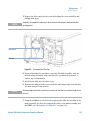
1 Remove the front cover by pressing the snap fasteners on both sides.
Figure 10
Removing the Front Cover
2 Place the solvent cabinet on top of the module.
3 Place the bottle into the solvent cabinet and place a bottle head assembly
into the bottle. Ground the solvent bottle!
4 Connect the solvent tubes from the bottle head assemblies to the inlet
adapters of the pump. Fix the tubes in the clips of solvent cabinet and
preparative pump.
5 By holding a piece of sanding paper around the waste tubing connect it to
the electromagnetic purge valve (EMPV) and place it into your waste
system.
6 If the preparative pump is not part of an Agilent 1260 Infinity system stack
or placed on the bottom of a stack, connect the corrugated waste tube to the
waste outlet of the pump leak handling system.
NOTE
In order to guarantee an error-free handling of any leakage that may occur in the system, all
modules of a stack must be thoroughly aligned on top of each other. Outstanding knobs at
the rear of the top covers of the modules and holes as counterparts at the rear of the
bottom covers of the modules will help to align the instruments nicely on top of each other
by making them slide into the correct position. This will then allow any possible spills to be
routed safely from one instrument to the next one with the help of the built in leak drainage
system. (Each module has a funnel to catch drops coming from the above instrument, from
there spills a lead through a waste drain tube into the leak pan and out from there through
an outlet on to the next module).
Agilent 1260 Infinity Preparative Pump User Manual
43
3
Installing the Pump
Flow Connections for a Single (Isocratic) Preparative Pump
7 Connect the Outlet Capillary (G1361-67302) to the electromagnetic purge
valve (EMPV) and make the necessary connections the other side of the
capillary (normally a capillary to an injector or injection valve).
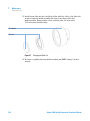
8 Install the seal wash tubings, as shown in Figure 11 on page 44. You need a
tubing from your seal wash solvent bottle to the seal wash pump, one from
there to the pump head and one from the pump head to waste.
9 Install the front cover.
10 Press in the power switch to turn ON the preparative pump.
;gdbhdakZciWdiiaZ
DjiaZiWVaakVakZh
IjWZXa^e
AZV`[jccZa
AZV`YgV^cV\Z
IjW^c\/HZValVh]
idlVhiZ
>caZiWVaakVakZh
:BEKdjiid
cZmibdYjaZ
;gdbhZValVh]hdakZciWdiiaZidhZValVh]ejbe
HZValVh]ejbeidejbe]ZVY
Figure 11
44
:BEKidlVhiZ
LVhiZdjiaZi"Xdggj\ViZYlVhiZijW^c\
Flow connections to the preparative pump
Agilent 1260 Infinity Preparative Pump User Manual
3
Installing the Pump
Flow Connections for a Dual (Binary Gradient) Preparative Pump
Flow Connections for a Dual (Binary Gradient) Preparative Pump
Tools required
Wrench 1/4 - 5/16 inch for capillary connections
Parts required
#
Part number
Description
Other modules
Preparations
WA R N I N G
1
G1361-68708
Parts from basis kit (see Table 8 on page 32)
1
G1361-68707
Parts from gradient kit (see Table 9 on page 33)
•
Pumps are installed in the HPLC system
When opening capillary or tube fittings solvents may leak out.
The handling of toxic and hazardous solvents and reagents can hold health risks.
➔ Please observe appropriate safety procedures (for example, goggles, safety gloves
and protective clothing) as described in the material handling and safety data sheet
supplied by the solvent vendor, especially when toxic or hazardous solvents are
used.
WA R N I N G
Danger of Explosion
Pumping solvents at high flow rates generally results in electrostatic charging of
the solvents, which may result in the potential ignition of flammable vapors or
solvents.
➔ To avoid electrostatic discharge, never use the pump without grounded metal
solvent bottles.
➔ Do not use metal bottles without appropriate grounding!
Agilent 1260 Infinity Preparative Pump User Manual
45
3
Installing the Pump
Flow Connections for a Dual (Binary Gradient) Preparative Pump
1 Remove the front covers of both pumps by pressing the snap fasteners on
both sides.
Figure 12
Removing the Front Cover
2 Place the solvent cabinet on top of the module.
3 Place the bottles into the solvent cabinet and place a bottle head assembly
into each bottle. Ground the solvent bottles!
4 Connect the solvent tubes from the bottle head assemblies to the inlet
adapters of the pumps. Fix the tubes in the clips of solvent cabinet and
preparative pumps.
5 By holding a piece of sanding paper around the waste tubing connect it to
the electromagnetic purge valve (EMPV) of each pump and place it into your
waste system.
6 If one of the preparative pumps is placed on the bottom of a stack, connect
the corrugated waste tube to the waste outlet of the pump leak handling
system.
NOTE
46
In order to guarantee an error-free handling of any leakage that may occur in the system, all
modules of a stack must be thoroughly aligned on top of each other. Outstanding knobs at
the rear of the top covers of the modules and holes as counterparts at the rear of the
bottom covers of the modules will help to align the instruments nicely on top of each other
by making them slide into the correct position. This will then allow any possible spills to be
routed safely from one instrument to the next one with the help of the built in leak drainage
system. (Each module has a funnel to catch drops coming from the above instrument, from
there spills a lead through a waste drain tube into the leak pan and out from there through
an outlet on to the next module).
Agilent 1260 Infinity Preparative Pump User Manual
3
Installing the Pump
Flow Connections for a Dual (Binary Gradient) Preparative Pump
7 Connect the long capillary (300 mm, G1361-67306) to the electromagnetic
purge valve (EMPV) of the upper pump and connect the female T-piece to
the other end of the capillary.
8 Connect the medium length capillary (140 mm, G1361-67304) to the
electromagnetic purge valve (EMPV) of the lower pump and connect the
other end of the capillary to the female T-piece.
9 Install the mixer (79835-87330) in the clips on the front panel of the bottom
pump.
10 Connect the capillary (G1361-67305) from the outlet of the female T-piece
to the mixer.
11 Install the outlet capillary (G1361-67302) to the mixer and make the
necessary connections the other side of the capillary (normally a capillary
to an injector or injection valve).
12 Install the seal wash tubings, as shown in Figure 13 on page 48. You need for each of the pumps - a tubing from your seal wash solvent bottle to the
seal wash pump, one from there to the pump head and one from the pump
head to waste.
13 Install the front cover.
Agilent 1260 Infinity Preparative Pump User Manual
47
3
Installing the Pump
Flow Connections for a Dual (Binary Gradient) Preparative Pump
14 Press in the power switch to turn ON the preparative pumps.
;gdbhdakZciWdiiaZ6
DjiaZiWVaakVakZh
IjWZXa^e
AZV`[jccZa
IjW^c\/
HZValVh]idlVhiZ
AZV`YgV^cV\Z
>caZiWVaakVakZh
:BEKdjiid
Wdiidbejbe
<&(+&"+,(%+
;gdbhZValVh]
hdakZciWdiiaZ
;gdbhdakZciWdiiaZ7
;ZbVaZI"e^ZXZ
IjW^c\/
HZValVh]idlVhiZ
<&(+&"+,(%*
B^mZg
<&(+&"+,(%)
HZValVh]ejbe
idejbe]ZVY
:BEKidlVhiZ%-.%"%+&*
;gdbhZValVh]hdakZciWdiiaZidhZValVh]ejbe
LVhiZdjiaZi"Xdggj\ViZYlVhiZijW^c\
Figure 13
48
B^mZgdjiidcZmibdYjaZ<&(+&"+,(%'
Flow connections to the preparative pump
Agilent 1260 Infinity Preparative Pump User Manual
3
Installing the Pump
Get the System Ready for the First Analysis
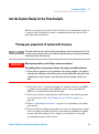
Get the System Ready for the First Analysis
When you are using the system for the first time it is recommended to prime it
to remove all the air and the possible contamination introduced in the flow
path during the installation.
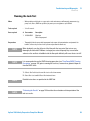
Priming your preparative LC system with the pump
NOTE
WA R N I N G
The pump should never be used for priming empty tubings (never let the pump run dry). Use
a syringe to draw enough solvent for completely filling the tubings to the pump inlet before
continuing to prime with the pump.
When opening capillary or tube fittings solvents may leak out.
The handling of toxic and hazardous solvents and reagents can hold health risks.
➔ Please observe appropriate safety procedures (for example, goggles, safety gloves
and protective clothing) as described in the material handling and safety data sheet
supplied by the solvent vendor, especially when toxic or hazardous solvents are
used.
1 Set the flow rate to 5 ml/min and pump for 5 minutes with an open EMPV
to prime your new tubings and capillaries and to remove potential air
bubbles or contamination from the flow path.
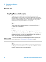
2 Check your system for leak tightness with the help of the built in pressure
test (see Pressure Test) (“Prep Pump Pressure Test Description” on
page 94).
3 Refer to “Optimizing Performance” on page 65 for optimizing your pump’s
performance.
4 Before starting an analysis pump until you receive a stable pressure signal
from your pump and until your detector baseline has stabilized (normally
no more than five minutes). Low %-ripple is a vital sign for a smoothly
operating pump and a stable system.
Agilent 1260 Infinity Preparative Pump User Manual
49
3
Installing the Pump
Get the System Ready for the First Analysis
5 When the pumping system has been turned OFF for a certain time (for
example, overnight) repeat Step 3 (step 4 on page 49).
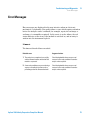
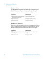
Table 10
Activity
Solvent
Comments
•
•
After an installation
When switching between
reverse phase and normal
phase (both times)
Isopropanol
Best solvent to flush air out of the
system
•
After an installation
Ethanol or Methanol
Alternative to Isopropanol (second
choice) if no Isopropanol is available
•
To clean the system when
using buffers
After a solvent change
Bidistilled water
Best solvent to re-dissolve salts
After the installation of
normal phase solvents
Hexane + 5% Isopropanol
Good wetting properties
•
•
50
Choice of Priming Solvents for Different Purposes
Agilent 1260 Infinity Preparative Pump User Manual
Agilent 1260 Infinity Preparative Pump User Manual
4
Using the Preparative Pump
Hints for Successful Use of the Preparative Pump
Solvent Information
52
53
Prevent Blocking of Solvent Filters
54
Algae Growth in HPLC Systems 55
How to Prevent and/or Reduce the Algae Problem
56
Setting Up the Pump 57
Setting up the Preparative Pump (Agilent ChemStation)
Agilent Technologies
57
51
4
Using the Preparative Pump
Hints for Successful Use of the Preparative Pump
Hints for Successful Use of the Preparative Pump
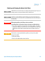
• Flush the pump extensively, when changing to a new solvent.
• The system pressure must be higher than 20 bar at the pump outlet for
optimum performance of the pump.
• Place the solvent cabinet with the solvent bottles always on top of the
preparative pump (or at a higher level).
• Prevent blocking of solvent inlet filters (never use the pump without solvent
inlet filters). Growth of algae should be avoided (see “Prevent Blocking of
Solvent Filters” on page 54).
• Regularly clean the filter cup and the filter frit installed in the multi
assembly. A back pressure greater than 10 bar, when pumping pure HPLC
grade water at a flow rate of 50 ml/min while the EMPV is open indicates
that one of the two filters is blocked or that the EMPV does not switch
(open) properly. Make sure to follow the correct procedures for cleaning
filters (see “Simple Repairs” on page 114) and the EMPV (see “Prep Pump
EMPV Cleaning Description” on page 103). Always clean the pump’s filters,
after exchanging seals.
• Confirm that the pump and the rest of the system are completely leak tight
by performing the built in Leak-test (see “Prep Pump Leak Test
Description” on page 98) and Pressure-test (see “Prep Pump Pressure Test
Description” on page 94), regularly.
• When using buffer solutions, flush the system with plenty of water to
remove all buffer solution from the entire system before switching it OFF or
before changing to an organic solvent.
• Always use the seal wash function.
• Check the pump seals. Scratched plungers will lead to micro leaks and will
decrease the lifetime of the seal.plungers for scratches when changing the
piston.
• For the generation of gradients in systems with multiple pump setups make
sure that none of the pumps delivers less than a minimum flow rate of
5 ml/min at any time during the gradient run, in order to achieve best
performance.
52
Agilent 1260 Infinity Preparative Pump User Manual
4
Using the Preparative Pump
Solvent Information
Solvent Information
Always filter solvents through 0.4 µm filters, small particles can permanently
block the capillaries and valves. Avoid the use of the following steel-corrosive
solvents:
• Solutions of alkali halides and their respective acids (for example, lithium
iodide, potassium chloride, and so on).
• High concentrations of inorganic acids like sulfuric and nitric acid,
especially at higher temperatures (replace, if your chromatography method
allows, by phosphoric acid or phosphate buffer which are less corrosive
against stainless steel).
• Halogenated solvents or mixtures which form radicals and/or acids, for
example:
2CHCl3 + O2 → 2COCl2 + 2HCl
This reaction, in which stainless steel probably acts as a catalyst, occurs
quickly with dried chloroform if the drying process removes the stabilizing
alcohol.
• Chromatographic grade ethers, which can contain peroxides (for example,
THF, dioxane, di-isopropylether). Such ethers should be filtered through
dry aluminium oxide which adsorbs the peroxides.
• Solvents containing strong complexing agents (e.g. EDTA).
• Mixtures of carbon tetrachloride with 2-propanol or THF dissolve stainless
steel.
Agilent 1260 Infinity Preparative Pump User Manual
53
4
Using the Preparative Pump
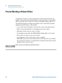
Prevent Blocking of Solvent Filters
Prevent Blocking of Solvent Filters
Contaminated solvents or algae growth in the solvent bottle will reduce the
lifetime of the solvent filter and will influence the performance of the module.
This is especially true for aqueous solvents or phosphate buffers (pH 4 to 7).
The following suggestions will prolong lifetime of the solvent filter and will
maintain the performance of the module.
• Use a sterile, if possible amber, solvent bottle to slow down algae growth.
• Filter solvents through filters or membranes that remove algae.
• Exchange solvents every two days or refilter.
• If the application permits add 0.0001-0.001M sodium azide to the solvent.
• Place a layer of argon on top of your solvent.
• Avoid exposure of the solvent bottle to direct sunlight.
• Filter HPLC grade (dry) Acetonitrile before use. The dryer the Acetornitrile,
the stronger the tendency to form polymers and therefore block the system.
Refilter at least every two days.
NOTE
54
Never use the system without solvent filter installed.
Agilent 1260 Infinity Preparative Pump User Manual
4
Using the Preparative Pump
Algae Growth in HPLC Systems
Algae Growth in HPLC Systems
The presence of algae in HPLC systems can cause a variety of problems that
may be incorrectly diagnosed as instrument or application problems. Algae
grow in aqueous media, preferably in a pH range of 4-8. Their growth is
accelerated by buffers, for example phosphate or acetate. Since algae grow
through photosynthesis, light will also stimulate their growth. Even in distilled
water small-sized algae grow after some time.
Instrumental Problems Associated With Algae
Algae deposit and grow everywhere within the HPLC system causing:
• Deposits on ball valves, inlet or outlet, resulting in unstable flow or total
failure of the pump.
• Small pore solvent inlet filters to plug, resulting in unstable flow or total
failure of the pump.
• Small pore high pressure solvent filters, usually placed before the injector
to plug resulting in high system pressure.
• Column filters to plug giving high system pressure.
• Flow cell windows of detectors to become dirty resulting in higher noise
levels (since the detector is the last module in the flow path, this problem is
less common).
Agilent 1260 Infinity Preparative Pump User Manual
55
4
Using the Preparative Pump
Algae Growth in HPLC Systems
Symptoms Observed with the Agilent 1260 Infinity HPLC
In contrast to the HP 1090 and HP 1050 Series HPLC systems which use
helium degassing, algae have a better chance to grow in systems such as the
Agilent 1260 Infinity Series where helium is not used for degassing (most algae
need oxygen and light for growth).
The presence of algae in the Agilent 1260 Infinity Series can cause the
following to occur:
• Short lifetime of solvent filters (bottle head assembly). A blocked solvent
filter in the bottle, especially when only partly blocked, is more difficult to
identify and may show up as gradient performance problems, intermittent
pressure fluctuations etc.
• Algae growth may also be the possible source for failures of the ball valves
and other components in the flow path.
How to Prevent and/or Reduce the Algae Problem
• Always use freshly prepared solvents, especially use demineralized water
which was filtered through about 0.2 µm filters.
• Never leave mobile phase in the instrument for several days without flow.
• Always discard “old” mobile phase.
• Use the amber solvent bottle (part number 9301-1450) supplied with the
instrument for your aqueous mobile phase.
• If possible add a few mg/l sodium azide or a few percent organic solvent to
the aqueous mobile phase.
56
Agilent 1260 Infinity Preparative Pump User Manual
4
Using the Preparative Pump
Setting Up the Pump
Setting Up the Pump
Setting up the Preparative Pump (Agilent ChemStation)
The Agilent 1260 Infinity Preparative Pump can be operated as Isocratic Pump
or can be combined with an additional pump to form a gradient system.
Details for both pump configurations are explained in “Flow Connections for a
Single (Isocratic) Preparative Pump” on page 42 for the isocratic pump and in
“Flow Connections for a Dual (Binary Gradient) Preparative Pump” on
page 45 for the gradient pump.
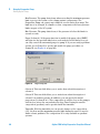
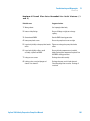
If the Agilent ChemStation software is started, all pumps that are connected
to the LC system are recognized and can be added to the list of configured
modules (see Figure 14 on page 57). If two pumps are configured, they are
treated as preparative gradient pump. The first (upper) pump in the
configuration will deliver solvent A and the second (lower) pump will deliver
solvent B.
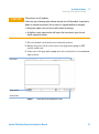
Figure 14
List of Configured Modules
Agilent 1260 Infinity Preparative Pump User Manual
57
4
Using the Preparative Pump
Setting Up the Pump
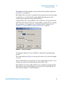
The parameters for setting up the preparative pump can be accessed through
the instrument menu or by clicking on the pump icon in the system diagram
(see Figure 15 on page 58).
Figure 15
System Diagram
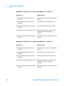
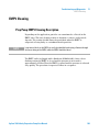
The Setup dialog box depends on the configuration of the pump. In Figure 16
on page 58 you see the dialog box for the isocratic pump and in Figure 17 on
page 59 you see the interface for the gradient pump.
Figure 16
58
Setup dialog box (isocratic pump)
Agilent 1260 Infinity Preparative Pump User Manual
4
Using the Preparative Pump
Setting Up the Pump
Figure 17
Setup dialog box (gradient pump)
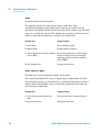
In these dialog boxes you can specify the following parameters:
Flow: Flow rate delivered by the pump. For gradient systems the flow
parameter defines the combined flow delivered by the system on channel A
and B. The maximum settable flow is 100 ml/min. For best performance a flow
above 5 ml/min should be chosen. The pump can be operated at lower flow
rates. However a slightly higher pressure ripple will be observed. In addition
the system pressure should always be kept above 20 bar.
Stop Time: The Stop Time defines the end of your analysis run. After the stop
time all gradients are stopped and the pump settings return to the initial
values. Typically, the Stop Time of the pump specifies the Stop Time for all
other modules in the LC system.
Post Time: During the Post Time the instrument stays in the Not Ready state
and delays the start of the next analysis. The Post Time allows the column to
equilibrate after a gradient run.
Agilent 1260 Infinity Preparative Pump User Manual
59
4
Using the Preparative Pump
Setting Up the Pump
Max Pressure: The pump shuts down when exceeding the maximum pressure
limit to protect the system or the column against overpressure. The
Preparative Pump can operate up to 400 bar over the entire flow range. The
limit has to be changed, if columns or other components with lower pressure
limits are part of the LC system.
Min. Pressure: The pump shuts down, if the pressure is below this limit for
several seconds.
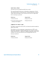
Purge (Solvent A): If the purge function is enabled, the purge valve (EMPV)
will open for the specified time before each analysis. In this dialog box, you
can only control the automated purge for pump A. If you are using a gradient
system, choose Purge B to specify and enable the purge procedure on
channel B (see Figure 18 on page 60).
Figure 18
Purge Dialog Box
Solvent A: This text field allows you to write down a brief description of
solvent A.
Solvent B: This text field allows you to write down a brief description of
solvent B on gradient systems. In addition, you can specify the initial
proportion of solvent B in %. This composition is valid as soon as the pump is
switched on, before the run and after the Stop Time. During the run the
composition (gradient) can be specified with the timetable.
Timetable: With the timetable you can specify changes of the composition
(%B), the flow and the maximum pressure limit during the run. It is used to
define solvent gradients. The composition %B is only available on gradient
systems.
60
Agilent 1260 Infinity Preparative Pump User Manual
4
Using the Preparative Pump
Setting Up the Pump
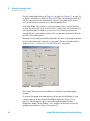
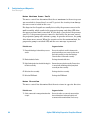
Flow Ramp and Compressibility can be specified in the Auxiliary dialog box
(see Figure 19 on page 61).
Flow Ramp: This is the rate for turning the flow up and down, when the pump
is switched on or off. The default setting (800 ml/min/min) protects the
column against sudden pressure peaks and drops.
Compressibility: The compressibility of the solvent has to be specified in this
field. The value will be used for the compressibility compensation to optimize
the performance of the pump. For more details read the chapter “How to
Optimize the Compressibility Compensation Setting” on page 67.
Figure 19
Auxiliary Dialog Box
The Auxiliary dialog box is also available for channel B on gradient pump
systems.
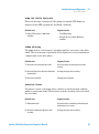
The Control dialog box (Figure 20 on page 62) allows you to switch the pump
on an off.
Purge: In this field you can open and close the automated purge valve, or you
can specify a time for how long the purge valve will be open.
Error Method: By setting an Error Method you can define a pump particular
method that is run, if an instrument error is detected. It is typically used to
shut down the pump in a controlled manner.
Agilent 1260 Infinity Preparative Pump User Manual
61
4
Using the Preparative Pump
Setting Up the Pump
Use the Setup Pump dialog box (Figure 16 on page 58 or Figure 17 on page 59)
to define a suitable error method. Then select Take Current Method and click
OK. The current method is immediately copied to the pump and stored as
error method and executed in case of an instrument error.
Seal Wash Pump: The settings for seal wash pump can be controlled in this
section. The seal wash can be switched off or a single wash can be started for a
user-specified time. In addition, you can choose to turn the seal wash on
periodically for a user-defined on-time. The on-time must be between 0.1 min
and 70% of the entire period.
Running the seal wash periodically will reduce the ware of the pump seals and
increase the maintenance interval of your pump. For more details read the
chapter “How to Configure the Seal Wash Function” on page 66.
Figure 20
Control dialog box
The Control dialog box is also available for channel B on gradient pump
systems.
To prevent the pump from running dry you can specify the fillings of your
solvent reservoir in the Solvent Bottle Filling dialog box (Figure 21 on
page 63). This dialog box can be opened through Instrument > More
Preparative pump > Bottle Filling… or by clicking on the bottle icon in the
graphical user interface (Figure 14 on page 57).
62
Agilent 1260 Infinity Preparative Pump User Manual
4
Using the Preparative Pump
Setting Up the Pump
Actual Volume: Set the actual volume after refilling the solvent bottle. When
turning on the pump, the current filling will be calculated based on the flow
rate and the run-time of the pump.
Total Volume: This value is used to calculate the % filling of the bottle for the
display in the system diagram.
You can select not to start the run, if the current fill level is below a
user-defined value, and to turn-off the pump before it is running out off
solvent.
Figure 21
Solvent Bottle Filling dialog box
The Solvent Bottle Filling dialog box is also available for channel B on gradient
pump systems.
Agilent 1260 Infinity Preparative Pump User Manual
63
4
64
Using the Preparative Pump
Setting Up the Pump
Agilent 1260 Infinity Preparative Pump User Manual
Agilent 1260 Infinity Preparative Pump User Manual
5
Optimizing Performance
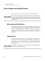
How to Configure the Seal Wash Function 66
Water or Aqueous Buffer Solutions 66
Organic Solvents 66
How to Optimize the Compressibility Compensation Setting
Agilent Technologies
67
65
5
Optimizing Performance
How to Configure the Seal Wash Function
How to Configure the Seal Wash Function
Always use the seal wash function which is delivered with your pump.
NOTE
The seal wash function cannot be operated permanently (danger of overheating). Switch on
the seal wash pump in regular intervals (normally for 30 s every 30 minutes) for a certain
length of time. It is however important to keep the back of the seals wet with the help of the
seal wash function.
Water or Aqueous Buffer Solutions
We recommend a composition of 10% Isopropanol in HPLC grade water for
water or aqueous buffer solutions. With buffer solutions, the seal wash pump
should be configured such, that it is turned on for a duration of 30 s every
5 minutes (with a maximum of 30% cycle time). Shorten the intervals between
the pump turn-ons for highly concentrated buffer solutions (> 0.1 M buffer
solutions).
Organic Solvents
For all organic non buffered solutions, we recommend to use the same solvent
for the seal wash as the one that is currently pumped by your preparative
pump. In this case, the seal wash pump has to be operated in large intervals,
only. Basically it is enough to keep the back of seals wet with the help of the
seal wash option.
NOTE
66
Beware that the seal wash tubing is made of silicon. Never use any solvents for the seal
wash, that are not compatible with silicone.
Agilent 1260 Infinity Preparative Pump User Manual
Optimizing Performance
How to Optimize the Compressibility Compensation Setting
5
How to Optimize the Compressibility Compensation Setting
The compressibility compensation default settings are 75 × 10-6 /bar (best for
most aqueous solutions). Under normal conditions the default settings reduce
the pressure pulsation to values (below 2 % of system pressure for a complete
system with a preparative scale sized column installed) that will be sufficient
for most applications. If the compressibility values for the solvents used differ
from the default settings, it is recommended to change the compressibility
values accordingly. Compressibility settings can be optimized by using the
values for various solvents described in Table 11 on page 68. If the solvent in
use is not listed in the compressibility table, when using premixed solvents
and if the default settings are not sufficient for your application the following
procedure can be used to optimize the compressibility settings:
NOTE
Use the preparative pump with a flow rate of at least 20 ml/min.
1 Start the preparative pump with the adequate flow rate. The system
pressure should be between 50 and 150 bar
2 Before starting the optimization procedure, the flow must be stable. Before
starting the procedure, check the tightness of the system with the help of
the built in pressure test (see “Prep Pump Pressure Test Description” on
page 94).
3 Verify the tightness of the pump itself (piston/seal combinations, valves,
filters fittings, etc.) with the help of the built in Leak Test (see “Prep Pump
Leak Test Description” on page 98).
4 Your pump must be connected to a Agilent ChemStation or handheld
controller, the pressure and %-ripple can be monitored with one of these
instruments.
5 Starting with a compressibility setting of 50 × 10-6 /bar increase the value
in steps of 10. The compressibility compensation setting that generates the
smallest pressure ripple is the optimum value for your solvent composition.
6 Repeat step 1 on page 67 through step 5 on page 67 for each preparative
pump in a system with a multiple pump setup.
Agilent 1260 Infinity Preparative Pump User Manual
67
5
Optimizing Performance
How to Optimize the Compressibility Compensation Setting
Table 11
68
Solvent Compressibility
Solvent (pure)
Compressibility (10-6/bar)
Acetone
126
Acetonitrile
115
Benzene
95
Carbon tetrachloride
110
Chloroform
100
Cyclohexane
118
Ethanol
114
Ethyl acetate
104
Heptane
120
Hexane
150
Isobutanol
100
Isopropanol
100
Methanol
120
1-Propanol
100
Toluene
87
THF
95
Water
46
Agilent 1260 Infinity Preparative Pump User Manual
Agilent 1260 Infinity Preparative Pump User Manual
6
Troubleshooting and Diagnostics
Agilent Lab Advisor software
70
Overview of the Pump’s Indicators and Test Functions
71
Status Indicators 72
Power Supply Indicator 72
Instrument Status Indicator 73
User Interfaces
74
Error Messages
75
Pressure Test 94
Prep Pump Pressure Test Description
Positioning the Blank Nut 95
Running the Pressure Test 96
Evaluating the Results 97
Leak Test 98
Prep Pump Leak Test Description
Running the Leak Test 99
Evaluating the Results 100
94
98
EMPV Cleaning 103
Prep Pump EMPV Cleaning Description
Running the Cleaning Procedure 104
103
Agilent Technologies
69
6
Troubleshooting and Diagnostics
Agilent Lab Advisor software
Agilent Lab Advisor software
The Agilent Lab Advisor software is a standalone product that can be used
with or without data system. Agilent Lab Advisor software helps to manage
the lab for high quality chromatographic results and can monitor in real time a
single Agilent LC or all the Agilent GCs and LCs configured on the lab
intranet.
Agilent Lab Advisor software provides diagnostic capabilities for all Agilent
1260 Infinity HPLC modules. This includes tests and calibrations procedures
as well as the different injector steps to perform all the maintenance routines.
A Agilent Lab Advisor software also allows users to monitor the status of their
LC instruments. The Early Maintenance Feedback (EMF) feature helps to
carry out preventive maintenance. In addition, users can generate a status
report for each individual LC instrument. The tests and diagnostic features as
provided by the Agilent Lab Advisor software may differ from the descriptions
in this manual. For details refer to the Agilent Lab Advisor software help files.
This manual provides lists with the names of
, Not Ready messages, and other common issues.
70
Agilent 1260 Infinity Preparative Pump User Manual
Troubleshooting and Diagnostics
Overview of the Pump’s Indicators and Test Functions
6
Overview of the Pump’s Indicators and Test Functions
This chapter describes the instrument’s built in troubleshooting and test
functions.
Status Indicators
The preparative pump is provided with two status indicators which indicate
the operational state (prerun, run, and error states) of the preparative pump.
The lower left indicates the power supply status, the upper right indicates the
preparative pump status.The status indicators provide a quick visual check of
the operation of the preparative pump (see “Status Indicators” on page 72).
Error Messages
In the event of an electronic, mechanical or hydraulic failure, the preparative
pump generates an error message in the user interface. For details on error
messages and error handling, please refer to the Agilent Lab Monitor &
Diagnostic Software.
Pressure Test
The pressure test is a quick test designed to determine the pressure tightness
of the system. After exchanging flow path components (e.g., pump seals or
injection seal), use this test to verify the system is pressure tight up to 400 bar
(see “Prep Pump Pressure Test Description” on page 94).
Leak Test
The leak test is a diagnostic test designed to determine the pressure tightness
of the preparative pump. When a problem with the preparative pump is
suspected, use this test to help troubleshoot the preparative pump and its
pumping performance (see “Prep Pump Leak Test Description” on page 98).
Agilent 1260 Infinity Preparative Pump User Manual
71
6
Troubleshooting and Diagnostics
Status Indicators
Status Indicators
Two status indicators are located on the front of the preparative pump. The
lower left one indicates the power supply status, the upper right one indicates
the instrument status.
HiVijh^cY^XVidg
EdlZghjeean^cY^XVidg
Power Supply Indicator
The power supply indicator is integrated into the main power switch. When
the indicator is illuminated (green) the power is ON.
NOTE
72
The power switch stays pressed in and a green indicator lamp in the power switch is ON
when the preparative pump is turned ON. When the line power switch stands out and the
green light is OFF, the preparative pump is turned OFF.
Agilent 1260 Infinity Preparative Pump User Manual
Troubleshooting and Diagnostics
Status Indicators
6
Instrument Status Indicator
The instrument status indicator indicates one of four possible instrument
conditions:
• When the status indicator is OFF (and power switch light is ON), the
module is in aprerun condition, and is ready to begin an analysis.
• A green status indicator, indicates the module is performing an analysis
(run mode).
• A yellow indicator indicates a not-ready condition. The module is in a
not-ready state when it is waiting for a specific condition to be reached or
completed (for example, immediately after changing a setpoint), or while a
self-test procedure is running.
• An error condition is indicated when the status indicator is red. An error
condition indicates the module has detected an internal problem which
affects correct operation of the module. Usually, an error condition requires
attention (for example, leak, defective internal components). An error
condition always interrupts the analysis.
• A flashing yellow status indicator indicates that the module is in its
resident mode. Call your local service provider for assistance upon
observing this error condition.
• A flashing red status indicator indicates a severe error during the startup
procedure of the module. Call your local service provider for assistance
upon observing this error condition.
Agilent 1260 Infinity Preparative Pump User Manual
73
6
Troubleshooting and Diagnostics
User Interfaces
User Interfaces
Depending on the User Interface, the available test vary. Some descriptions
are only available in the Service Manual.
Table 12
74
Test Functions available vs. User Interface
Test
ChemStation
Instant Pilot
G4208A
Agilent Lab
Monitoring &
Diagnostic
Software
Pressure Test
Yes
No
Yes
Leak Test
Yes
No
Yes
EMPV Cleaning
Yes
No
Yes
Agilent 1260 Infinity Preparative Pump User Manual
6
Troubleshooting and Diagnostics
Error Messages
Error Messages
Error messages are displayed in the user interface when an electronic,
mechanical, or hydraulic (flow path) failure occurs which requires attention
before the analysis can be continued (for example, repair, frit exchange or
exchange of consumables required). In the event of such a failure, the red
status indicator at the front of the module is switched on, and an entry is
written into the instrument logbook.
Timeout
The timeout threshold was exceeded.
Probable cause
Suggested actions
1 The analysis was completed successfully,
Check the logbook for the occurrence and
source of a not-ready condition. Restart the
analysis where required.
and the timeout function switched off the
module as requested.
2 A not-ready condition was present during a
sequence or multiple-injection run for a
period longer than the timeout threshold.
Agilent 1260 Infinity Preparative Pump User Manual
Check the logbook for the occurrence and
source of a not-ready condition. Restart the
analysis where required.
75
6
Troubleshooting and Diagnostics
Error Messages
Shut-Down
An external instrument has generated a shut-down signal on the remote line.
The module continually monitors the remote input connectors for status
signals. A LOW signal input on pin 4 of the remote connector generates the
error message.
Probable cause
Suggested actions
1 Leak detected in another module with a CAN Fix the leak in the external instrument before
connection to the system.
restarting the module.
2 Leak detected in an external instrument with Fix the leak in the external instrument before
a remote connection to the system.
restarting the module.
3 Shut-down in an external instrument with a
remote connection to the system.
Check external instruments for a shut-down
condition.
Remote Timeout
A not-ready condition is still present on the remote input.
When an analysis is started, the system expects all not-ready conditions (e.g. a
not-ready condition during detector balance) to switch to run conditions
within one minute of starting the analysis. If a not-ready condition is still
present on the remote line after one minute the error message is generated.
Probable cause
Suggested actions
1 Not-ready condition in one of the
Ensure the instrument showing the not-ready
condition is installed correctly, and is set up
correctly for analysis.
instruments connected to the remote line.
2 Defective remote cable.
Exchange the remote cable.
3 Defective components in the instrument
Check the instrument for defects (refer to the
instrument’s reference documentation).
showing the not-ready condition.
76
Agilent 1260 Infinity Preparative Pump User Manual
6
Troubleshooting and Diagnostics
Error Messages
Synchronization Lost
During an analysis, the internal synchronization or communication between
one or more of the modules in the system has failed.
The system processors continually monitor the system configuration. If one or
more of the modules is no longer recognized as being connected to the system,
the error message is generated.
Probable cause
Suggested actions
1 CAN cable disconnected.
•
Ensure all the CAN cables are connected
correctly.
•
Ensure all CAN cables are installed correctly.
2 Defective CAN cable.
Exchange the CAN cable.
3 Defective main board in a different module.
Switch off the system. Restart the system, and
determine which module or modules are not
recognized by the system.
Agilent 1260 Infinity Preparative Pump User Manual
77
6
Troubleshooting and Diagnostics
Error Messages
Leak
A leak was detected in the module.
The signals from the two temperature sensors (leak sensor and
board-mounted temperature-compensation sensor) are used by the leak
algorithm to determine whether a leak is present. When a leak occurs, the leak
sensor is cooled by the solvent. This changes the resistance of the leak sensor
which is sensed by the leak-sensor circuit on the main board.
Probable cause
Suggested actions
1 Loose fittings.
Ensure all fittings are tight.
2 Broken capillary.
Exchange defective capillaries.
3 Loose or leaking active inlet valve, outlet ball Ensure pump components are seated correctly.
valve, or EMPV.
If there are still signs of a leak, exchange the
appropriate seal (active inlet valve, outlet ball
valve, or EMPV).
4 Defective pump seals.
Exchange the pump seals.
Leak Sensor Open
The leak sensor in the module has failed (open circuit).
The current through the leak sensor is dependent on temperature. A leak is
detected when solvent cools the leak sensor, causing the leak-sensor current to
change within defined limits. If the current falls outside the lower limit, the
error message is generated.
Probable cause
Suggested actions
1 Leak sensor not connected to the main
Ensure the leak sensor is connected correctly.
board.
2 Defective leak sensor.
78
Exchange the leak sensor.
Agilent 1260 Infinity Preparative Pump User Manual
Troubleshooting and Diagnostics
Error Messages
6
Leak Sensor Short
The leak sensor in the module has failed (short circuit).
The current through the leak sensor is dependent on temperature. A leak is
detected when solvent cools the leak sensor, causing the leak-sensor current to
change within defined limits. If the current increases above the upper limit,
the error message is generated.
Probable cause
Suggested actions
1 Defective leak sensor.
Exchange the leak sensor.
2 Leak sensor incorrectly routed, being
Exchange the leak sensor.
pinched by a metal component.
Compensation Sensor Open
The ambient-compensation sensor (NTC) on the main board in the module has
failed (open circuit).
The resistance across the temperature compensation sensor (NTC) on the
main board is dependent on ambient temperature. The change in resistance is
used by the leak circuit to compensate for ambient temperature changes. If the
resistance across the sensor increases above the upper limit, the error
message is generated.
Probable cause
Suggested actions
1 Defective main board.
Exchange the main board.
Agilent 1260 Infinity Preparative Pump User Manual
79
6
Troubleshooting and Diagnostics
Error Messages
Compensation Sensor Short
The ambient-compensation sensor (NTC) on the main board in the module has
failed (short circuit).
The resistance across the temperature compensation sensor (NTC) on the
main board is dependent on ambient temperature. The change in resistance is
used by the leak circuit to compensate for ambient temperature changes. If the
resistance across the sensor falls below the lower limit, the error message is
generated.
Probable cause
Suggested actions
1 Defective main board.
Exchange the main board.
Fan Failed
The cooling fan in the module has failed.
The hall sensor on the fan shaft is used by the main board to monitor the fan
speed. If the fan speed falls below a certain limit for a certain length of time,
the error message is generated.
Probable cause
Suggested actions
1 Fan cable disconnected.
Ensure the fan is connected correctly.
2 Defective fan.
Exchange fan.
3 Defective main board.
Exchange the main board.
4 Improperly positioned cables or wires
Ensure the fan is not mechanically blocked.
obstructing fan blades.
80
Agilent 1260 Infinity Preparative Pump User Manual
6
Troubleshooting and Diagnostics
Error Messages
Open Cover (Safety)
Do not remove instrument covers when operating. Before the instrument is
switched ON, all protective earth terminals, extension cords,
auto-transformers, and devices connected to it must be connected to a
protective earth via a ground socket. Any interruption of the protective earth
grounding will cause a potential shock hazard that could result in serious
personal injury. Whenever it is likely that the protection has been impaired,
the instrument must be made inoperative and be secured against any intended
operation.
WA R N I N G
Open main cover
The following procedures require opening the main cover of the instrument.
➔ Always ensure the instrument is disconnected from the line power when the main
cover is removed.
➔ The security lever at the power input socket prevents that the instrument cover is
taken off when line power is still connected.
WA R N I N G
Module is partially energized when switched off, as long as the power cord is
plugged in.
Repair work at the module can lead to personal injuries, e.g. shock hazard, when the
cover is opened and the module is connected to power.
➔ Make sure that it is always possible to access the power plug.
➔ Remove the power cable from the instrument before opening the cover.
➔ Do not connect the power cable to the Instrument while the covers are removed.
Agilent 1260 Infinity Preparative Pump User Manual
81
6
Troubleshooting and Diagnostics
Error Messages
Open Cover
The top foam has been removed.
The sensor on the main board detects when the top foam is in place. If the
foam is removed, the pump is turned OFF within 4s for safety reasons, and the
error message is generated. If the pump is started without cover, this error
message is also generated and the pump is not turned on.
Probable cause
Suggested actions
1 The top foam was removed during operation
Reinstall the top foam.
or pump started without cover.
2 Foam not activating the sensor.
Replace the top foam.
3 Sensor defective.
Exchange the main board.
4 Rear of the module is exposed to strong
Ensure that the rear of module is not directly
exposed to strong sunlight.
direct sunlight.
Pressure Above Upper Limit
The system pressure has exceeded the upper pressure limit. This error
condition automatically results in the opening of the purge valve.
Probable cause
Suggested actions
1 Upper pressure limit set too low.
Ensure the upper pressure limit is set to a value
suitable for the analysis.
2 Blockage in the flowpath (after the pressure
Check for blockage in the flowpath.
sensor).
82
3 Defective pressure sensor.
Exchange the Multi Assembly.
4 Defective main board.
Exchange the main board.
Agilent 1260 Infinity Preparative Pump User Manual
6
Troubleshooting and Diagnostics
Error Messages
Pressure Below Lower Limit
The system pressure has fallen below the lower pressure limit.
Probable cause
Suggested actions
1 Lower pressure limit set too high.
Ensure the lower pressure limit is set to a value
suitable for the analysis.
2 Air bubbles in the mobile phase.
Ensure bubble free flow. Purge the preparative
pump.
3 Leak.
•
Inspect the pump head, capillaries and
fittings for signs of a leak.
•
Purge the module. Run a pressure test to
determine whether the seals or other
module components are defective.
4 Defective pressure sensor.
Exchange the Multi Assembly.
5 Defective main board.
Exchange the main board.
Pressure Sensor not Connected
The pressure readings, read by the pump ADC (analog-digital converter), are
missing.
The ADC reads the pressure readings from the pressure sensor every 1 ms. If
the readings are missing for longer than 10 seconds, the error message is
generated.
Probable cause
Suggested actions
1 Pressure sensor not connected (should be
Ensure the pressure sensor connector is clean,
connected and seated correctly.
connected to P29 on the PPM board) or
connected to the seal wash cable connector
(P23).
2 Defective pressure sensor.
Exchange multi assembly.
3 Defective PPM board.
Exchange the PPM board.
Agilent 1260 Infinity Preparative Pump User Manual
83
6
Troubleshooting and Diagnostics
Error Messages
Wrong Data from Pressure Sensor
The pressure sensor delivers readings within the range of -5 to -25 bar.
Probable cause
Suggested actions
1 Defective pressure sensor.
Exchange the pressure sensor.
2 Defective PPM board.
Exchange the PPM board.
Motor Drive Temperature too High
The temperature of the motor-drive circuits is too high.
The processor continually monitors the temperature of the drive circuits on
the PPM board. If excessive current is being drawn for long periods, the
temperature of the circuits increase. If the temperature exceeds the upper
limit of 95 °C, the error message is generated.
Probable cause
Suggested actions
1 High friction (partial mechanical blockage) in Remove the pump head assembly. Ensure there
the pump drive assembly.
is no mechanical blockage of the pump head
assembly or pump drive assembly.
2 Partial blockage of the flowpath in front of
the pressure sensor.
84
•
Ensure the outlet valve is not blocked.
•
Ensure the capillaries and frits between the
pump head and pressure sensor (at the rear
of the multi assembly) are free from
blockage. Clean the filters in the multi
assembly.
3 Defective drive assembly.
Exchange defective drive assembly.
4 Defective PPM board.
Exchange the PPM board.
Agilent 1260 Infinity Preparative Pump User Manual
Troubleshooting and Diagnostics
Error Messages
6
Motor Drive Fault
The motor drive chip has issued a fault signal. The current drawn by the pump
motor exceeded the maximum limit or under voltage lockout.
Blockages in the flowpath are usually detected by the pressure sensor, which
result in the preparative pump switching OFF when the upper pressure limit
is exceeded. If a blockage occurs before the pressure sensor (i.e. the pressure
increase cannot be detected by the pressure sensor), the preparative pump
will continue to pump. As pressure increases, the pump drive draws more
current. When the current reaches the maximum limit, the preparative pump
is switched OFF, and the error message is generated.
Probable cause
Suggested actions
1 Flow path blockage in front of the pressure
Ensure the capillaries and frits between the
pump head and pressure sensor (at the rear of
the multi assembly) are free from blockage.
Clean the filters in the multi assembly.
sensor.
2 Blocked outlet ball valve.
Exchange the outlet ball valve.
3 High friction (partial mechanical blockage) in Remove the pump head assembly. Ensure there
the drive assembly.
is no mechanical blockage of the pump head
assembly or drive assembly.
4 Defective drive assembly.
Exchange the drive assembly.
5 Defective PPM board.
Exchange the PPM board.
Agilent 1260 Infinity Preparative Pump User Manual
85
6
Troubleshooting and Diagnostics
Error Messages
Motor Maximum Power Fault
The motor control has determined that the set maximum for the motor power
was exceeded for longer than 1 second. To protect the circuitry from damage
this error event is issued in this case.
Blockages in the flowpath are usually detected by the pressure sensor in the
multi assembly, which results in the preparative pump switching OFF when
the upper pressure limit is exceeded. If a blockage occurs before the pressure
sensor (i.e. the pressure increase cannot be detected by the pressure sensor),
the preparative pump will continue to pump. As pressure increases, the pump
drive draws more current. When the current reaches the maximum limit, the
preparative pump is switched OFF, and the error message is generated.
Probable cause
Suggested actions
1 Flow path blockage in front of the pressure
Ensure the capillaries and frits between the
pump head and pressure sensor (at the rear of
the multi assembly) are free from blockage.
Clean the filters in the multi assembly.
sensor.
2 Blocked outlet ball valve.
Exchange the outlet ball valve.
3 High friction (partial mechanical blockage) in Remove the pump head assembly. Ensure there
the drive assembly.
is no mechanical blockage of the pump head
assembly or drive assembly.
4 Defective drive assembly.
Exchange the drive assembly.
5 Defective PPM board.
Exchange the PPM board.
Motor Direction
The motor control has determined that the motor turns in opposite direction.
Probable cause
Suggested actions
1 Cables connected in wrong orientation after
Ensure the cables are correctly connected (on
the main board and at the pump drive) and
reconnect with new orientation, if necessary.
a repair.
86
Agilent 1260 Infinity Preparative Pump User Manual
Troubleshooting and Diagnostics
Error Messages
6
Pump Off While Analysis
This error message is generated, if the pump was turned OFF, during an
analysis (Power OFF or pump in a Not-Ready condition).
Probable cause
Suggested actions
1 Power OFF or pump in a Not-Ready
•
Turn ON the Pump.
•
Eliminate the cause of the Not-Ready
condition.
condition.
Index Missing
The pump motion control expects one index signal for every turn of the drive
wheel. The error message is generated, if this signal is not received within one
complete turn of the drive wheel.
Probable cause
Suggested actions
1 Defective or disconnected index cable.
Ensure the connector connected and seated
correctly.
2 Defective Pump drive defective index board
Exchange the pump drive assembly.
on pump drive.
3 Defective main board.
Exchange the main board.
Position Error
The motion control of the pump drive could not reach the desired condition
within a certain time frame. The deviation from the desired position exceeded
the error limit.
Probable cause
Suggested actions
1 Blocked flow path.
Ensure that there is no blockage in the flow path
before the pressure sensor.
2 Mechanical blockage of the pump drive
Exchange the pump drive assembly.
assembly.
Agilent 1260 Infinity Preparative Pump User Manual
87
6
Troubleshooting and Diagnostics
Error Messages
Spurious Index
The pump motion control expects one (and only one) index signal for every
turn of the drive wheel. This error message is generated, if this signal is
received more often than within one complete turn of the drive wheel.
Probable cause
Suggested actions
1 Missing reflections to light switch because
Ensure the drive wheel is clean.
of contamination on drive wheel.
2 Defective Pump drive.
Exchange the pump drive assembly.
3 Defective main board.
Exchange the main board.
Encoder not Connected
There is an encoder wheel mounted to the shaft of the pump motor, that gives
pulses to the motion control according to the rotation of the shaft. The error
message is generated if the short bridge on the connector is not sensed.
Probable cause
Suggested actions
1 Defective or disconnected pump encoder
Ensure the connector is clean, and seated
correctly.
connector or cable.
2 Defective main board.
88
Exchange main board.
Agilent 1260 Infinity Preparative Pump User Manual
Troubleshooting and Diagnostics
Error Messages
6
Purge Valve (EMPV) Fuse Blown
The electronic fuse has detected that the current through the purge valve was
too high.
Probable cause
Suggested actions
1 Defective purge valve.
Exchange the drive of the EMPV.
2 Defective PPM board.
Exchange the PPM board.
Electro-Magnetic-Proportional-Valve (EMPV) Missing
The EMPV in the preparative pump is missing or defective.
Probable cause
Suggested actions
1 Disconnected or defective cable.
Ensure the connection cable is seated correctly.
2 Defective purge valve.
Exchange the drive of the EMPV.
3 Defective PPM board.
Exchange PPM board.
No Pump Head
The pump-head RF-tag in the preparative pump was not found.
Probable cause
Suggested actions
1 Pump head not installed correctly (screws
Install the pump head correctly. Ensure nothing
(e.g. capillary) is trapped between the pump
head and body.
not secured, or pump head not seated
correctly).
2 RF-tag on pump-head missing or defective.
Install missing or replace defective RF-tag.
3 Wrong pump-head connected.
Install the original Agilent pump-head with
RF-tag.
4 Defective PPM board.
Exchange PPM board.
Agilent 1260 Infinity Preparative Pump User Manual
89
6
Troubleshooting and Diagnostics
Error Messages
Wait for Volume Timed Out
The wait time limit until a given volume has been pumped, has been exceeded.
Probable cause
Suggested actions
1 Wrong limit set for the time limit.
Set limit accordingly.
2 Flow setting too low.
Set flow accordingly.
Wait for Pressure Timed Out
The limit, for waiting until a given pressure is reached, has been exceeded.
Probable cause
Suggested actions
1 Wrong limit set for the time limit.
Set limit accordingly.
2 Leak.
Check for leaks with the help of the built in
pressure or leak test and correct them, where
necessary.
Composition Cluster Partner Lost
Communication to a composition cluster partner was interrupted.
In a gradient system, two (or more) isocratic preparative pumps can be linked
together in a cluster acting as one gradient pump. The error message is
generated, if the communication between the partners of a cluster is
interrupted.
Probable cause
Suggested actions
1 Composition cluster partner was turned OFF. Turn ON composition cluster partner.
2 CAN-cable to composition cluster partner
Reconnect or replace CAN-cable.
disconnected.
3 Defective CAN-bus.
90
Replace PPM main board.
Agilent 1260 Infinity Preparative Pump User Manual
Troubleshooting and Diagnostics
Error Messages
6
Solvent Counter Zero
The volume counter for the bottle filling reached zero.
Probable cause
Suggested actions
1 Value for bottle filling set incorrectly.
Reset bottle filling to the correct value.
2 Solvent bottle empty.
Refill solvent bottle.
No Motor Motion
No motor rotation feedback.
Probable cause
Suggested actions
1 Defective or disconnected index cable.
Ensure the connector connected and seated
correctly.
2 Encoder cable not connected at the encoder. Ensure the encoder cable is connected and
seated correctly at the encoder.
3 Motor defective or not connected.
Exchange the pump drive assembly.
4 Defective main board.
Exchange the main board.
Seal Wash Current Low
The current sensing of the seal wash motor was lower than expected.
Probable cause
Suggested actions
1 Defective or disconnected seal wash pump
•
Ensure the cable is correctly connected.
•
Exchange the seal wash pump motor.
motor.
2 Defective main board.
Agilent 1260 Infinity Preparative Pump User Manual
Exchange main board.
91
6
Troubleshooting and Diagnostics
Error Messages
Seal Wash (Safety)
CAUTION
Pressure sensor incorrectly plugged into the main board port
You risk permanent damage of the pressure sensor, if the seal wash pump is turned ON
while the pressure sensor is incorrectly connected to the main board port, dedicated
for the seal wash pump. This requires exchange of complete multi assembly.
➔ Never turn on the seal wash pump, while the pressure sensor is connected to the
main board port.
➔ Make sure the seal wash cable and the pressure sensor cable are plugged in the
correct positions before turning ON the seal wash pump.
Seal Wash
This error message is generated, if the pressure sensor is incorectly plugged
into the connector on the main board, that should hold the seal wash motor
cable.
Probable cause
Suggested actions
1 Pressure sensor and seal wash pump
Switch the connectors of the seal wash pump
cable and the pressure sensor to meet the
correct positions (P23 for seal wash cable, P29
for the pressure sensor cable from the multi
assembly).
connector were connected to the wrong
position on the main board (identical
connectors allow to plug into the wrong
positions by mistake).
Wait for Encoder Position Timed Out
Encoder position was not reached within specified time.
92
Probable cause
Suggested actions
1 Flow too low.
Recalculate flow or wait time, to allow to reach
encoder position before encoder position
time-out.
2 Pump OFF.
Turn ON pump.
Agilent 1260 Infinity Preparative Pump User Manual
Troubleshooting and Diagnostics
Error Messages
6
24V Supply for External Devices Low
Voltage sensing of the 24 Volts CAN outlet shows low voltage, probably fuse
has blown.
Probable cause
Suggested actions
1 Excessive current has been drawn by an
Ensure, that any device, connected to the
external 24 CAN-DC out, does not draw more
than 100 mA as a permanent current or a
maximum of 2 A for no longer than 2 seconds.
The error condition will be reset automatically,
when the excessive current is not drawn from
the external 24 CAN-DC out port any more.
external device connected to the external 24
CAN-DC out.
2 Defective main board.
Agilent 1260 Infinity Preparative Pump User Manual
Exchange main board.
93
6
Troubleshooting and Diagnostics
Pressure Test
Pressure Test
Prep Pump Pressure Test Description
The pressure test is a quick, built-in test designed to demonstrate the
pressure-tightness of the system. The test involves monitoring the flow rate,
required to keep a constant pressure of 350 bar, as the preparative pump runs
through a predefined pumping sequence. The resulting flow rate provides
information about the pressure tightness of the system.
Step 1
The test begins with an automated flushing of the pump at a flow rate of
25 ml/min with an open EMPV.
Step 2
The EMPV is closed and next, piston A begins pumping solvent with a flow
rate of 0.5 ml/min until reaching a pressure of 150 bar. At this point, the pump
delivers at a flow rate of 0.2 ml/min until reaching a pressure of 250 bar. The
pump then delivers at a flow rate of 0.1 ml/min until reaching a pressure of
345 bar, then switches into its “Keep pressure mode”.
NOTE
To test the pressure tightness of all individual components in the flow path of the pump
itself use the leak test, see “Prep Pump Leak Test Description” on page 98.
Step 3
When the system pressure reaches 350 bar, the preparative pump switches to
its “Keep-pressure-mode”. The flow rate to compensate for leaks should from
this point onwards be no more than 10 µl/minute.
94
Agilent 1260 Infinity Preparative Pump User Manual
Troubleshooting and Diagnostics
Pressure Test
6
Positioning the Blank Nut
If a specific component is suspected of causing a system leak, place the blank
nut immediately before the suspected component, then run the pressure test
again. If the test passes, the defective component is located after the blank nut.
Confirm the diagnosis by placing the blank nut immediately after the
suspected component. The diagnosis is confirmed if the test fails.
Agilent 1260 Infinity Preparative Pump User Manual
95
6
Troubleshooting and Diagnostics
Pressure Test
Running the Pressure Test
When
If problems with small leaks are suspected After maintenance of flow-path components (e.g. pump
seals, injection seal) to prove pressure tightness up to 350 bar.
Tools required
•
¼-inch” wrench
Parts required
#
Part number
Description
1
01080-83202
Blank nut
500 ml Isopropanol
Preparations
NOTE
•
Thoroughly flush the entire system with Isopropanol and remove all contaminations and
potential air bubbles, release the pressure in the system and position the blank nut
Make absolutely sure that all parts of the flow path that are part of the test are very
thoroughly flushed with IPA before starting to pressurize the system! Any trace of other
solvents or the smallest air bubble inside the flow path definitely will cause the test to fail!
1 Select the pressure test from the test selection menu.
2 Start the test and follow the instructions.
NOTE
Finishing the test will release the pressure in the system.
3 Remove the blanking nut after finishing the test and reconnect all
capillaries.
NOTE
96
For detailed instructions refer to the Agilent LMD Tool.
Agilent 1260 Infinity Preparative Pump User Manual
6
Troubleshooting and Diagnostics
Pressure Test
Evaluating the Results
The sum of all leaks between the pump and the blank nut will be indicated by
flow rate of > 10 µl/minute to keep the pressure constant. Note that small
leaks may cause the test to fail, but solvent may not be seen leaking from a
module.
NOTE
Please notice the difference between an error in the test and a failure of the test! An error
means that during the operation of the test there was an abnormal termination. If a test
failed, this means that the results of the test where not within the specified limits.
NOTE
Do not overtighten fittings! After the first major increase of resistance when tightening a
previously loose fitting, the fitting should not be tightened any further than an additional
1/8 to 1/4 wrench turn.
NOTE
Often it is only a damaged blank nut itself (poorly shaped from overtightening) that causes
a failure of the test. Before investigating on any other possible sources of failure make sure
that the blank nut you are using is in good condition and properly tightened!
Large internal leaks at the EMPV can easily be identified by observing a flow
out through the waste tubing of the EMPV, while the EMPV should be closed.
Agilent 1260 Infinity Preparative Pump User Manual
97
6
Troubleshooting and Diagnostics
Leak Test
Leak Test
Prep Pump Leak Test Description
The leak test is a quick, built-in test designed to demonstrate the
pressure-tightness of the pump. The test involves monitoring the pump drive
steps needed to build up a pressure of 350 bar and the flow rate, required to
keep a constant pressure of 350 bar, as the preparative pump runs through a
predefined pumping sequence. The resulting flow rate provides information
about the pressure tightness of the pump. Each step is separately performed
and evaluated separately for piston 1 and piston 2.
Step 1
The test begins with an automated flushing of the pump at a flow rate of
25 ml/min with an open EMPV.
Step 2
The EMPV is closed and next, piston 1 begins pumping solvent with a flow rate
of 2 ml/min until reaching a pressure of 150 bar, then the pump delivers at a
flow rate of 0.2 ml/min until reaching a pressure of 250 bar, then the pump
delivers at a flow rate of 0.1 ml/min until reaching a pressure of 345 bar, then
the pump switches into its “Keep pressure mode”.
Step 3
The flow rate to compensate for leaks should from this point onwards be no
more than 10 µl/minute.
Step 4
Steps 2 and 3 are automatically repeated for piston 2.
98
Agilent 1260 Infinity Preparative Pump User Manual
6
Troubleshooting and Diagnostics
Leak Test
Running the Leak Test
When
•
When problems with leaks are suspected, or after maintenance of flow-path components (e.g.,
pump seals, filters, EMPV or capillaries) to prove pressure tightness up to 350 bar
Tools required
•
¼ inch” wrench.
Parts required
#
Part number
Description
1
01080-83202
Blank nut
500 ml Isopropanol
Preparations
•
Thoroughly flush the pump with isopropanol and remove all contaminations and potential air
bubbles, release the pressure in the system and position the blank nut,
NOTE
Make absolutely sure that all parts of the flow path that are part of the test are very
thoroughly flushed with IPA before starting to pressurize the pump! Any trace of other
solvents or the smallest air bubble inside the flow path definitely will cause the test to fail!
NOTE
It is recommended to run the EMPV cleaning procedure (see “Prep Pump EMPV Cleaning
Description” on page 103) prior to running the Leak test, to remove any potential deposits
from the EMPV valve.
1 Select the leak test from the test selection menu.
2 Start the test and follow the instructions.
NOTE
Detailed instructions are provided in the LMD Tool.
NOTE
“Evaluating the Results” on page 100 describes the evaluation and interpretation of the
leak test results.
Agilent 1260 Infinity Preparative Pump User Manual
99
6
Troubleshooting and Diagnostics
Leak Test
Evaluating the Results
Defective or leaky components in the pump head lead to changes in the
leak-test pressure plot. Typical failure modes are described below.
NOTE
Please notice the difference between an error in the test and a failure of the test! An error
means that during the operation of the test there was an abnormal termination. If a test
failed, this means that the results of the test were not within the specified limits.
NOTE
Often it is only the damaged blank nut itself (poorly shaped from overtightening) that
causes a failure of the test. Before investigating on any other possible sources of failure
make sure that the blank nut you are using is in good condition and properly tightened!
Error Limits Exceeded for One or Both of the Encoder
Values and One or Both of the Maximum allowed Flow
Rates in the Constant Pressure Mode
Probable cause
Suggested actions
1 Air bubble.
Flush pump thoroughly.
2 Loose or leaky fittings.
Ensure all fittings are tight, or exchange
capillary.
3 Large leaks (visible) at the pump seals.
Exchange the pump seals.
4 Large leaks (visible) at valve, outlet valve,
Ensure the leaky components are installed
tightly. Exchange the component if required. Run
the EMPV cleaning procedure.
filters, multi assembly, capillaries or EMPV.
100
Agilent 1260 Infinity Preparative Pump User Manual
6
Troubleshooting and Diagnostics
Leak Test
Maximum Allowed Flow Rate Exceeded for Both Pistons (1
and 2)
Probable cause
Suggested actions
1 Wrong solvent.
Use Isopropyl alcohol only.
2 Loose or leaky fittings.
Ensure all fittings are tight, or exchange
capillary.
3 Contaminated EMPV.
Run the EMPV cleaning procedure.
4 Loose pump head screws.
Ensure the pump head screws are tight.
5 Large leaks (visible) at the pump inlet/outlet Tighten or exchange the pump inlet/outlet
valves.
6 Large leaks (visible) at filters, multi
assembly, capillaries or EMPV.
valves.
Ensure the leaky components are installed
tightly. Exchange the component if required. Run
the EMPV cleaning procedure.
7 Leaky pressure sensor.
Exchange the multi assembly.
8 Leaking seal or scratched plungers of
Exchange the pump seals in both channels.
Check the plungers for scratches. Exchange if
scratched.
channel 1 or channel 2.
Agilent 1260 Infinity Preparative Pump User Manual
101
6
Troubleshooting and Diagnostics
Leak Test
Maximum Allowed Flow Rate exceeded for Piston 1
Probable cause
Suggested actions
1 Externally leaking inlet or outlet valve in
Ensure the valves are installed correctly. Tighten
the valves.
channel 1.
2 Internally leaking inlet valve in channel 1
Clean or replace the inlet valve in channel 1.
(back flow).
3 Internally leaking outlet valve in channel 2
Clean or replace the outlet valve in channel 2.
(back flow).
4 Leaking seal or scratched plunger in channel Exchange the pump seals in channel 1. Check
1.
the plunger for scratches. Exchange if
scratched.
5 Loose or leaky fitting or capillary or fitting in
channel 1.
Tighten fitting or replace capillary if necessary in
channel 1.
Maximum Allowed Flow Rate Exceeded for Piston 2
Probable cause
Suggested actions
1 Externally leaking inlet or outlet valve in
Ensure the valves are installed correctly. Tighten
the valves.
channel 2.
2 Internally leaking inlet valve in channel 2
Clean or replace the inlet valve in channel 2.
(back flow).
3 Internally leaking outlet valve in channel 1
Clean or replace the outlet valve in channel 1.
(back flow).
4 Leaking seal or scratched plunger in channel Exchange the pump seals in channel 2. Check
2.
the plunger for scratches. Exchange if
scratched.
5 Loose or leaky fitting or capillary or fitting in
channel 2.
102
Tighten fitting or replace capillary if necessary in
channel 2.
Agilent 1260 Infinity Preparative Pump User Manual
6
Troubleshooting and Diagnostics
EMPV Cleaning
EMPV Cleaning
Prep Pump EMPV Cleaning Description
Depending on the application, particles can sometimes be collected in the
EMPV valve. This fast cleaning routine is designed to remove such particle
deposits. The routine should always be performed when the EMPV is
suspected of being leaky or contaminated with particles.
NOTE
Large internal leaks at the EMPV can easily be identified by observing a flow out through
the waste tubing of the EMPV, while the EMPV should be closed.
The EMPV outlet is plugged with a blank nut (01080-83202). After a short
flushing routine the EMPV is closed and the pressure is increased to
approximately 350 bar. Then the EMPV is opened and the pressure is released
very quickly. The procedure is repeated 5 times in a sequence.
Agilent 1260 Infinity Preparative Pump User Manual
103
6
Troubleshooting and Diagnostics
EMPV Cleaning
Running the Cleaning Procedure
When
•
When the EMPV is suspected of being leaky, or contaminated with particles
Tools required
•
Wrench7/16 inch.
Parts required
#
Part number
Description
1
01080-83202
Blank nut
Preparations
•
Plug the pump outlet with a blank nut (01080-83202) at EMPV outlet
1 Select EMPV Cleaning from the test selection menu.
2 Start the procedure and follow the instructions.
104
NOTE
Detailed instructions are provided in the Lab Advisor tool.
NOTE
Run a leak test (see “Prep Pump Leak Test Description” on page 98 after having performed
the cleaning procedure, to ensure tightness of the EMPV.
Agilent 1260 Infinity Preparative Pump User Manual
Troubleshooting and Diagnostics
EMPV Cleaning
6
3 For better removal of any left-over particles, it will help to clean the ball of
the valve with an additional procedure, if the previous step did not help:
Using a 7/16” wrench remove deposits by turning the holding screw of the
EMPV body back and forth about 1/4 wrench turn several times.
Figure 22
Removing Deposits from the EMPV with the Help of a Wrench:
4 Remove the blank nut.
5 Reconnect all capillaries.
Agilent 1260 Infinity Preparative Pump User Manual
105
6
106
Troubleshooting and Diagnostics
EMPV Cleaning
Agilent 1260 Infinity Preparative Pump User Manual
Agilent 1260 Infinity Preparative Pump User Manual
7
Maintenance
Introduction to Maintenance and Repair
Simple Repairs 108
Warnings and Cautions 109
Cleaning the module 111
Overview of Maintenance and Repair
108
112
Simple Repairs 114
Checking and Cleaning the Solvent Inlet Filters 115
Exchanging the Inlet/Outlet Ball Valves 117
Exchanging the Filter Cup 120
Exchanging the Filter Frit 122
Exchanging the Seal Wash Pump Cartridge 125
Removing and Disassembling the Pump Head Assembly
Reassembling the Pump Head Assembly 129
Exchanging the Optional Interface Board 131
Replacing the Module’s Firmware 132
Agilent Technologies
126
107
7
Maintenance
Introduction to Maintenance and Repair
Introduction to Maintenance and Repair
Simple Repairs
The module is designed for easy repair. The most frequent repairs such as
plunger seal change and purge valve frit change can be done from the front of
the module with the module in place in the system stack.
These repairs are described in “Simple Repairs” on page 114
108
Agilent 1260 Infinity Preparative Pump User Manual
7
Maintenance
Introduction to Maintenance and Repair
Warnings and Cautions
WA R N I N G
Module is partially energized when switched off, as long as the power cord is
plugged in.
Repair work at the module can lead to personal injuries, e.g. shock hazard, when the
cover is opened and the module is connected to power.
➔ Make sure that it is always possible to access the power plug.
➔ Remove the power cable from the instrument before opening the cover.
➔ Do not connect the power cable to the Instrument while the covers are removed.
WA R N I N G
Sharp metal edges
Sharp-edged parts of the equipment may cause injuries.
➔ To prevent personal injury, be careful when getting in contact with sharp metal
areas.
WA R N I N G
When opening capillary or tube fittings solvents may leak out.
The handling of toxic and hazardous solvents and reagents can hold health risks.
➔ Please observe appropriate safety procedures (for example, goggles, safety gloves
and protective clothing) as described in the material handling and safety data sheet
supplied by the solvent vendor, especially when toxic or hazardous solvents are
used.
CAUTION
Electronic boards and components are sensitive to electrostatic discharge (ESD).
ESD can damage electronic boards and components.
➔ Be sure to hold the board by the edges and do not touch the electrical
components.Always use an ESD protection (for example, an ESD wrist strap) when
handlingelectronic boards and components.
Agilent 1260 Infinity Preparative Pump User Manual
109
7
Maintenance
Introduction to Maintenance and Repair
NOTE
110
The electronics of the preparative pump will not allow operation of the preparative pump
when the top cover and the top foam are removed. A safety light switch ON the main board
will inhibit the operation of the preparative pump. Always operate the preparative pump
with the top foam and top covers in place.
Agilent 1260 Infinity Preparative Pump User Manual
7
Maintenance
Introduction to Maintenance and Repair
Cleaning the module
The module case should be kept clean. Cleaning should be done with a soft
cloth slightly dampened with water or a solution of water and mild detergent.
Do not use an excessively damp cloth as liquid may drip into the module.
WA R N I N G
Liquid dripping into the electronic compartment of your module.
Liquid in the module electronics can cause shock hazard and damage the module.
➔ Do not use an exessively damp cloth during cleaning.
➔ Drain all solvent lines before opening any fittings.
Agilent 1260 Infinity Preparative Pump User Manual
111
7
Maintenance
Overview of Maintenance and Repair
Overview of Maintenance and Repair
Figure 23 on page 112 shows the main assemblies of the preparative pump.
The pump heads and its parts do require normal maintenance (for example,
seal exchange) and can be accessed from the front (simple repairs). Replacing
internal parts will require to remove the module from its stack and to open the
top cover.
,
+
-
.
*
)
(
&%
'
&&
&
Figure 23
112
Overview of Repair Procedures
Agilent 1260 Infinity Preparative Pump User Manual
Maintenance
Overview of Maintenance and Repair
11
Multi assembly with filters and pressure sensor (at the rear), see “Exchanging the Filter
Cup” on page 120, “Exchanging the Filter Frit” on page 122
22
Leak sensor, see Exchanging the Leak Sensorin the Service Manual
33
Inlet valves, see “Removing an Inlet Ball Valve (Bottom of the Pump Head)” on page 117
44
Pump head, see “Removing and Disassembling the Pump Head Assembly” on page 126
55
Outlet valves, see “Removing an Outlet Ball Valve (Top of the Pump Head)” on page 118
66
Pump drive, see Exchanging a Pump Drive in the Service Manual
77
Power supply, see Exchanging a Power Supply in the Service Manual
88
PPM board, see Exchanging a PPM Board in the Service Manual
99
Fan, see Exchanging a Fan in the Service Manual
1010
Electromagnetic purge valve, EMPV, see Exchanging a EMPV in the Service Manual
1111
Seal wash pump, see “Exchanging the Seal Wash Pump Cartridge” on page 125
Agilent 1260 Infinity Preparative Pump User Manual
7
113
7
Maintenance
Simple Repairs
Simple Repairs
The procedures described in this section can be done with the preparative
pump in place in the system stack.
Table 13
Simple Repair Procedures
Procedure
Symptom
Potential causes
“Removing an Inlet Ball Valve (Bottom of the
Pump Head)” on page 117
If leaking or not
opening/closing properly
External/internal leak. Pressure ripple unstable,
run leak test for verification
“Exchanging the Filter Cup” on page 120
Excessive back pressure
with open EMPV,
unstable pressure
After replacing pump seals,
contaminated filter
“Exchanging the Filter Frit” on page 122
Excessive back pressure
with open EMPV,
unstable pressure
After replacing filter cup,
particles on filter frit
“Exchanging the Seal Wash Pump
Cartridge” on page 125
Seal wash pump not
delivering flow
Seal wash pump leaking
If mechanically defect
“Removing and Disassembling the Pump
Head Assembly” on page 126
Leaks, unstable flow or
pressure
If seal life time is shorter than normally
expected — check plungers for scratches while
changing the seals
“Reassembling the Pump Head
Assembly” on page 129
After pumphead repair
114
Agilent 1260 Infinity Preparative Pump User Manual
7
Maintenance
Simple Repairs
Checking and Cleaning the Solvent Inlet Filters
NOTE
A blocked filter does not affect the pressure readings of the preparative pump. The pressure
readings cannot be used to check whether the filter is blocked or not.
NOTE
If the filter is in good condition the solvent will freely run out of the solvent tube (due to
hydrostatic pressure). If the solvent filter is partly blocked only little solvent will drip out of
the solvent tube.
WA R N I N G
When opening capillary or tube fittings solvents may leak out.
The handling of toxic and hazardous solvents and reagents can hold health risks.
➔ Please observe appropriate safety procedures (for example, goggles, safety gloves
and protective clothing) as described in the material handling and safety data sheet
supplied by the solvent vendor, especially when toxic or hazardous solvents are
used.
CAUTION
Small particles can permanently block the capillaries and valves of the module.
Damage of the module.
➔ Always filter solvents.
➔ Never use the module without solvent inlet filter.
Agilent 1260 Infinity Preparative Pump User Manual
115
7
Maintenance
Simple Repairs
Cleaning the Solvent Filters
When
If solvent filter is blocked
Parts required
#
Description
Concentrated nitric acid (65%)
Bidistilled water
1
Preparations
Beaker
Remove the solvent inlet tube from the inlet valve of the pump and let the tube hang down
1 Remove the blocked solvent filter from the bottle-head assembly and place
it in a beaker with concentrated nitric acid (65%) for one hour.
2 Thoroughly flush the filter with bidistilled water (remove all nitric acid,
some columns can be damaged by nitric acid).
3 Replace the filter.
116
Agilent 1260 Infinity Preparative Pump User Manual
7
Maintenance
Simple Repairs
Exchanging the Inlet/Outlet Ball Valves
Removing an Inlet Ball Valve (Bottom of the Pump Head)
When
If internally / externally leaking (back flow)
Tools required
•
•
Parts required
#
Part number
Description
1
G1361-60012
Valve assembly
NOTE
Wrench 17 mm
Wrench 1/4 inch
The inlet valves do not necessarily have to be replaced in pairs. Use the built in Leak Test
(see “Prep Pump Leak Test Description” on page 98) to identify the valve, that is not
working properly.
1 Disconnect the solvent inlet tube at the inlet valve. Beware of leaking
solvents.
2 Using a 17-mm wrench loosen the inlet valve and remove the valve adapter,
including the valve assembly from the pump head.
KVakZVhhZbWan
KVakZVYVeiZg
Figure 24
Ball Valve Parts
Agilent 1260 Infinity Preparative Pump User Manual
117
7
Maintenance
Simple Repairs
Removing an Outlet Ball Valve (Top of the Pump Head)
When
If internally / externally leaking (back flow)
Tools required
•
•
Parts required
#
Part number
Description
1
G1361-60012
Valve assembly
NOTE
Wrench 17 mm
Wrench 1/4 inch
The outlet valves do not necessarily have to be replaced in pairs. Use the built in Leak Test
(see “Prep Pump Leak Test Description” on page 98) to identify the valve, that is not
working properly.
1 Disconnect the solvent outlet capillary at the valve adapter, with a 1/4 inch
wrench. Beware of leaking solvents.
2 Using a 17-mm wrench loosen the outlet valve adapter and remove the valve
adapter from pump head.
3 Lift the valve adapter out of the housing in the pumphead.
4 With a pair of tweezers carefully remove valve assembly.
Replacing an Inlet/Outlet Valve
1 Before inserting the new valve assembly, clean the valve adapter by placing
it into an ultrasonic bath, if it shows visible signs of contamination. Clean
the valve housing in the pumphead by filling a syringe with alcohol and
flushing the housing thoroughly.
2 Insert a new valve assembly into the valve adapter. The arrow on Figure 24
on page 117 indicates the flow direction. Make sure the valve assembly is
fully inserted into the valve adapter.
NOTE
The side of the valve assembly that has the two holes must always face in flow direction!
3 Insert the valve adapter with the new valve assembly into the housing and
screw tight.
4 Reconnect all capillaries and tubings.
118
Agilent 1260 Infinity Preparative Pump User Manual
Maintenance
Simple Repairs
NOTE
7
Don’t reverse inlet and outlet valve adapters. The outlet valve adapters have a smaller hole
for fitting of the SST outlet capillary. The inlet adapters are designed for the finger tight
fittings of the inlet tubing.
Agilent 1260 Infinity Preparative Pump User Manual
119
7
Maintenance
Simple Repairs
Exchanging the Filter Cup
When
•
•
After the pump seals have been exchanged
When the back pressure exceeds 10 bar pumping 50 ml/min of pure water with open purge
valve.
Tools required
•
•
Wrench 17 mm
Wash bottle containing isopropanol
Parts required
#
Part number
Description
1
3150-0942
Filter cup
NOTE
Whenever replacing the filters on the multi assembly is required because of a pump seal
change or because excessive back pressure indicates the need for a replacement, make
sure to replace the filter cup first and then the filter frit (see “Exchanging the Filter Frit” on
page 122), after having pumped another 200 ml of solvent.
NOTE
It is not possible to clean a contaminated filter cup in an ultrasonic bath because any
contamination of the filter is normally permanent.
1 Using a 17 mm wrench loosen filter screw on the multi assembly.
2 Carefully pull out filter screw and filter cup.
120
Agilent 1260 Infinity Preparative Pump User Manual
7
Maintenance
Simple Repairs
3 Remove the filter cup from the screw by holding the screw and filter and
pulling them apart.
NOTE
Generally, all components which are in direct contact with solvents should be handled
wearing gloves.
;^aiZghXgZl
;^aiZgXje
Figure 25
Exchanging the Filter Cup
4 Before reinserting the new filter screw into the multi assembly, wash the
filter housing thoroughly with a wash bottle, containing Isopropanol, to
remove any contamination.
5 Install a new filter into the filter screw.
6 Reinsert the filter and filter screw and turn until finger tight, then another
1/8 turn using a 17 mm wrench.
NOTE
Do not overtighten the filter screw. Excessive force on the filter screw doesn’t help in case
of a leak.
7 Pump about 200 ml of solvent before replacing the filter frit installed at the
multi assembly: the filter frit between the outlet of the multi assembly and
the EMPV (see “Exchanging the Filter Frit” on page 122).
Agilent 1260 Infinity Preparative Pump User Manual
121
7
Maintenance
Simple Repairs
Exchanging the Filter Frit
NOTE
Whenever replacing the filters on the multi assembly is required because of a pump seal
change or because excessive back pressure indicates the need for a replacement, make
sure to replace the filter cup first (see “Exchanging the Filter Cup” on page 120) and then
the filter frit, after having pumped another 200 ml of solvent.
Changing the Filter Frit
When
When the back pressure exceeds 10 bar pumping 50 ml/min of pure water with open purge valve.
After 200 ml solvent have been pumped through the pump after a filter cup exchange.
Tools required
•
•
•
•
Parts required
#
Part number
Description
1
5022-2192
Filter frit 2 µm
Wrench 7/16 inch
Wrench 1/4 inch
Hex-key 4 mm
Wash bottle containing Isopropanol
1 Using a 1/4 inch wrench disconnect the capillary between multi assembly
and EMPV.
122
Agilent 1260 Infinity Preparative Pump User Manual
7
Maintenance
Simple Repairs
2 Insert a hex-key in to hole in the multi assembly. Hold the hex-key firmly
and unscrew the locknut using the 7/16 inch wrench.
;^aiZg[g^i
=daZ
;^aiZg]daYZg
Figure 26
Changing the Filter Frit
3 Pull out the filter holder and filter.
4 Flush the filter port and filter holder using a wash bottle containing
isopropanol.
Agilent 1260 Infinity Preparative Pump User Manual
123
7
Maintenance
Simple Repairs
5 Install a new filter frit into the filter holder with the collar of the filter frit
facing towards the multi assembly. Reconnect the filter holder into
multi-assembly. Finger tighten screw and then turn 1/8 turn using
7/16 inch wrench and hex-key.
;^aiZg]daYZg
;^aiZg[g^i
Figure 27
Changing the Filter Frit
6 Reconnect capillary between multi assembly and EMPV using a 1/4 inch
wrench.
124
Agilent 1260 Infinity Preparative Pump User Manual
7
Maintenance
Simple Repairs
Exchanging the Seal Wash Pump Cartridge
When
If mechanically defect
Parts required
#
Part number
Description
1
5042-8507
Seal wash pump cartridge
1 Disconnect seal wash tubing at the connectors, and place the ends of each
tubing at a level above seal wash bottle (to avoid leaking solvents).
2 By pressing the upper and lower clip remove the seal wash pump cartridge.
3 Replace the defective cassette and slide the new cassette on to the shaft
pressing upper and lower clip. Push forward until the clips snap into place.
The preferred orientation of the cartridge is as shown in picture below.
4 Reconnect seal wash tubing.
HZValVh]XdccZXidgh
Figure 28
Seal Wash Pump Cartridge
Agilent 1260 Infinity Preparative Pump User Manual
125
7
Maintenance
Simple Repairs
Removing and Disassembling the Pump Head Assembly
When
•
•
•
When leaky or blocked
For exchanging the seals
For exchanging the plungers
Tools required
•
•
•
•
Screwdriver Pozidrive#1
4-mm hexagonal key
10-mm wrench
Toothpick
Preparations
•
•
Switch OFF preparative pump at power switch
Remove the front cover to have access to the pump mechanics
NOTE
CAUTION
Seals should always be replaced as pairs (2x front seals + 2x back seals)!
Damage of the pump drive
Starting the pump when the pump head is removed may damage the pump drive.
➔ Never start the pump when the pump head is removed.
126
Agilent 1260 Infinity Preparative Pump User Manual
Maintenance
Simple Repairs
1 Disconnect the capillaries at the outlet valves and the
tubes at the inlet valves. Beware of leaking solvents.
Remove seal wash tubes.
DjiaZiXVe^aaVg^Zh
7
2 Using a 4-mm hexagonal key step wise loosen and
remove the four pump head screws and remove the pump
head from the pump drive.
Ejbe]ZVYhXgZlh
>caZiijW^c\h
3 Place the pump head on a flat surface facedown. Pull out 4 Loosen the two screws on the spring assembly and
the plungers from the spring assembly.
Eajc\Zgh
carefully pull the spring assembly and pumphead apart
HXgZlh
Heg^c\VhhZbWan
=daY]ZgZ
Ejbe]ZVY
Heg^c\VhhZbWan
Agilent 1260 Infinity Preparative Pump User Manual
127
7
Maintenance
Simple Repairs
5 Remove secondary seals between the pumphead and the spring assembly, by using the plungers.
HZXdcYVgnhZVah
128
Agilent 1260 Infinity Preparative Pump User Manual
7
Maintenance
Simple Repairs
Reassembling the Pump Head Assembly
Tools required
•
•
•
Screwdriver Pozidrive#1
4-mm hexagonal key
10-mm wrench
Preparations
Clean all parts before reassembly
1 Place front pump head facedown on a flat surface. Insert 2 Take rear pump head and place on top of front pump head.
new seals with the spring facing the pump body. Press
the seals firmly into place. Make sure not to damage seal
surface.
Beware that the O-rings are in proper place and the seal
wash fitting is facing in same direction as outlet valves.
EjbehZVah
HZValVh][^ii^c\
Ejbe]ZVY[gdci
Agilent 1260 Infinity Preparative Pump User Manual
DjiaZiWVaakVakZ
129
7
Maintenance
Simple Repairs
3 Insert and tighten special screws using a 10 mm wrench. 4 Insert new secondary seals with the spring facing the
pump body. Press the seals firmly into place.
HeZX^VahXgZlh
HZXdcYVgnhZVah
5 Place Spring assembly on special screws and tighten the 6 Reinsert Plungers by pushing until Plunger collars hit
two flathead screws using a pozidrive#1. The RF-tag
must be on the upper side of the pumphead.
springs.
;aVi]ZVYhXgZlh
Eajc\Zgh
Heg^c\VhhZbWan
G;"iV\
130
Agilent 1260 Infinity Preparative Pump User Manual
7
Maintenance
Simple Repairs
Exchanging the Optional Interface Board
When
Board defective
Parts required
#
Description
1
BCD (Interface) board, see “BCD / External Contact Board” on page 155
CAUTION
Electrostatic discharge at electronic boards and components
Electronic boards and components are sensitive to electrostatic discharge (ESD).
➔ ??8 In order to prevent damage always use an ESD protection (for example, the ESD
wrist strap from the accessory kit) when handling electronic boards and
components.
1 Switch off the pump at the main power switch, unplug the pump from line
power.
2 Disconnect cables from the interfaceboard connectors.
3 Loosen the screws. Slide out the interface board from the pump.
4 Install the new interface board. Secure screws.
5 Reconnect the cables to the board connector.
789>ciZg[VXZWdVgY
Figure 29
Exchanging the Interface Board
Agilent 1260 Infinity Preparative Pump User Manual
131
7
Maintenance
Simple Repairs
Replacing the Module’s Firmware
When
The installation of newer firmware might be necessary
• if a newer version solves problems of older versions or
• to keep all systems on the same (validated) revision.
The installation of older firmware might be necessary
• to keep all systems on the same (validated) revision or
• if a new module with newer firmware is added to a system or
• if third part control software requires a special version.
Tools required
•
•
•
LAN/RS-232 Firmware Update Tool or
Agilent Diagnostic Software
Instant Pilot G4208A (only if supported by module)
Parts required
Description
Firmware, tools and documentation from Agilent web site
Preparations
Read update documentation provided with the Firmware Update Tool.
To upgrade/downgrade the module’s firmware the following steps have to be
performed:
1 Download the required module firmware, the latest LAN/RS-232 FW
Update Tool and the documentation from the Agilent web.
• http://www.chem.agilent.com/scripts/cag_firmware.asp.
2 Load the firmware into the module as described in the documentation.
NOTE
132
Due to a different hardware platform, there is no way to convert a G1314D VWD and the
G1314E VWD SL Plus to a G1314A/B VWD or G1314C VWD SL.
Agilent 1260 Infinity Preparative Pump User Manual
Agilent 1260 Infinity Preparative Pump User Manual
8
Parts and Materials for Maintenance
Pump Housing and Main Assemblies
Pump-Head Assembly
138
Solvent Cabinet and Solvent Inlet Parts
Hydraulic Path
134
140
142
Preparative Pump Basis Kit
145
Preparative Pump Gradient Kit
147
Agilent Technologies
133
8
Parts and Materials for Maintenance
Pump Housing and Main Assemblies
Pump Housing and Main Assemblies
Table 14
134
Repair Parts — Pump Housing and Main Assemblies (Front View)
Item
Description
Part Number
1
Leak sensor
5061-3356
2
Multi assembly with filters and pressure sensor (at the rear)
Filter cup 10 µm
SST filter assembly — 2 µm
G1361-60005
3150-0942
5022-2192
3
Inlet valve, see “Removing an Inlet Ball Valve (Bottom of the Pump
Head)” on page 117
4
Pump head, see “Removing and Disassembling the Pump Head
Assembly” on page 126
5
Outlet valve, see “Removing an Outlet Ball Valve (Top of the Pump
Head)” on page 118
6
Cap, seal wash, see “Removing and Disassembling the Pump Head
Assembly” on page 126
7
Pump drive assembly
G1361-60001
8
Power supply, underneath the PPM board, main assembly only;
for additional parts refer to the Repair Manual
0950-3907
9
Main Board PPM
G1361-66500
10
Fan assembly
3160-1016
11
Electromagnetic purge valve (EMPV)
G1361-60000
12
Cassette — seal wash pump
Stepper motor — seal wash pump
5042-8507
5065-4409
13
Leak pan - pump
5042-8590
G1361-60004
Agilent 1260 Infinity Preparative Pump User Manual
Parts and Materials for Maintenance
Pump Housing and Main Assemblies
8
-
.
,
+
&%
*
)
(
&&
'
&
&'
&(
Figure 30
Overview of Main Assemblies (Front View)
Agilent 1260 Infinity Preparative Pump User Manual
135
8
Parts and Materials for Maintenance
Pump Housing and Main Assemblies
Table 15
136
Repair Parts — Pump Housing and Main Assemblies (Rear View)
Item
Description
Part Number
1
Power supply (behind rear panel)
0950-3907
2
Standoff — remote connector
1251-7788
3
Board cover
5001-3772
4
Screw
0515-0910
Lock washer
2190-0409
Agilent 1260 Infinity Preparative Pump User Manual
Parts and Materials for Maintenance
Pump Housing and Main Assemblies
8
)
(
'
&
Figure 31
Overview of Main Assemblies (Rear View)
Agilent 1260 Infinity Preparative Pump User Manual
137
8
Parts and Materials for Maintenance
Pump-Head Assembly
Pump-Head Assembly
Table 16
Item
138
Pump-Head Assembly
Description
Part Number
Complete assembly
G1361-60004
1
Screw M5, 55 mm lg
0515-4249
2
Pump head front (front and rear head sould be replaced at the
same time, it necessary)
G1361-25200
3
Valve assembly for inlet and outlet
G1361-60012
4
Adapter for outlet valve
G1361-23202
5
Special screw M6
G1361-22401
6
Cap seal wash fittings
G1361-67307
7
Screw for plunger housing
5015-0048
8
Sapphire plunger
G1361-22402
9
Plunger housing
G1361-60007
10
Seal prep flange
5022-2188
11
Pump head rear (front and rear head sould be replaced at the
same time, it necessary)
G1361-25201
12
O-ring
0905-1516
13
Adapter for inlet valve
G1361-23201
Agilent 1260 Infinity Preparative Pump User Manual
Parts and Materials for Maintenance
Pump-Head Assembly
8
,
+
*
.
)
&%
(
&&
&'
'
&%
&
(
&(
Figure 32
Pump-Head Assembly
Agilent 1260 Infinity Preparative Pump User Manual
139
8
Parts and Materials for Maintenance
Solvent Cabinet and Solvent Inlet Parts
Solvent Cabinet and Solvent Inlet Parts
Table 17
140
Solvent Cabinet and Bottle-Head Assembly Parts
Item
Description
Part Number
1
Solvent cabinet, including all plastic parts
5065-9981
2
Name plate, Agilent 1200
5042-8901
3
Front panel, solvent cabinet
5065-9990
4
Leak pan, solvent cabinet
5042-8907
5
Bottle-head assembly for Prep pump includes items 6, 7, 8, 9,
and 10
G1361-60022
6
Y-fitting and tube pump
7
Cap, bottle
8
Bottle amber, 2 liter
9301-6341
8
Bottle clear, 2 liter
9301-6342
Bottle clear, 2 liter, with second inlet
5065-4421
9
Frit adapter
G1361-23205
10
Solvent inlet filter
3150-0944
11
Prep. Pump SST inlet adapter for pressurized solvent supply.
Allows connection of any 1/8” Swagelock-compatible capillary
to the inlet of the prep. pump.
G1361-60008
12
HiFlow Solvent Inlet Filter Assembly, for high filtering capacity,
includes tubing and connectors
5065-4500
13
Replacement HiFlow Solvent Inlet Filter, glass housing with
filter
5065-9901
Agilent 1260 Infinity Preparative Pump User Manual
Parts and Materials for Maintenance
Solvent Cabinet and Solvent Inlet Parts
8
*
+
,
&
'
-
(
.!&%
)
&&
&'
&(
Figure 33
Solvent Cabinet and Solvent Inlet Parts
Agilent 1260 Infinity Preparative Pump User Manual
141
8
Parts and Materials for Maintenance
Hydraulic Path
Hydraulic Path
Table 18
142
Hydraulic Path
Item
Description
Part Number
1
Tubing from solvent bottle, see “Solvent Cabinet and Solvent
Inlet Parts” on page 140)
G1361-60022
2, 3
Tube clip, Leak funnel
5042-6404, 5042-6405
4
Leak drainage, same as item 7 (re-order 5 m)
5062-2463
5
Prep Capillary 3 (basis kit), EMPV out to next module, SST 1/16”
o.d., 0.6 mm i.d., 400 mm long
G1361-67302
5a
Prep Capillary 4, multi assembly to EMPV, SST 1/16” o.d.,
0.5 mm i.d., 160 mm long
G1361-67303
6
Tubing PTFE 0.057” i.d., EMPV to waste (re-order 5 m)
5062-2461
7
Corrugated waste tube, 120 cm (re-order 5 m)
5062-2463
8
Tubing, Seal wash pump to pump head
0890-1764
9
Tubing, Seal wash solvent bottle to seal wash pump
0890-1764
Tube adapter (for item 8 and 9)
5042-6422
10
Inlet ball valve, see “Pump-Head Assembly” on page 138
11
Outlet ball valve, see “Pump-Head Assembly” on page 138
12
Tubing, Seal wash to waste
0890-1764
13
Prep Capillary 1, Outlet valve 1 to multi assembly top, SST 1/16”
o.d., 0.6 mm i.d., 173 mm long
G1361-67300
14
Prep Capillary 2, Outlet valve 2 to multi assembly bottom, SST
1/16” o.d., 0.6 mm i.d., 178 mm long
G1361-67301
15
Prep Capillary 5 (gradient kit), Union to EMPV2 SST 1/16” o.d.,
0.6 mm i.d., 111 mm long
G1361-67304
16
Prep Capillary 6 (gradient kit), Union to mixer SST 1/16” o.d.,
0.6 mm i.d., 40 mm long
G1361-67305
Agilent 1260 Infinity Preparative Pump User Manual
Parts and Materials for Maintenance
Hydraulic Path
Table 18
8
Hydraulic Path
Item
Description
Part Number
17
Prep Capillary 7 (gradient kit), EMPV1 to union SST 1/16” o.d.,
0.6 mm i.d., 367 mm long
G1361-67306
18
Union (gradient kit)
0100-1016
Fitting FRONT, Fitting BACK, Fitting 1/16”, re-order 10/pk
5062-2418
Agilent 1260 Infinity Preparative Pump User Manual
143
8
Parts and Materials for Maintenance
Hydraulic Path
&
&)
'
&(
(
)
&'
&&
*V
*
&%
+
.
,
<gVY^Zci^ciZgXdccZXi^dc
Ejbe&
:BEK&
&,
Ejbe'
:BEK'
&*
Jc^dc
&+
B^mZg
144
*
8dajbc
Agilent 1260 Infinity Preparative Pump User Manual
Parts and Materials for Maintenance
Preparative Pump Basis Kit
8
Preparative Pump Basis Kit
This kit is part of the G1361A Preparative Pump.
Table 19
Basis Kit Contents G1361-68708 (shipped with the first pump of a system)
Description
Part Number
Quantity
Bottle head assembly
G1361-60022
1
Tube seal wash, 2 m
0890-1764
1
Waste tube, reorder No.
5062-2461
1
Capillary 3, pump outlet to system
G1361-67302
1
Bottle AMBER 2.0 l
9301-6341
1
Wrench open end 14-17 mm
8710-2435
1
Wrench open end 1/4-5/16"
8710-0510
2
Wrench open end 7/16-3/8”
8710-0972
1
Hex key 3 mm
8710-2411
1
Hex key 4 mm
8710-2392
1
Pair of tweezers
5022-2195
1
Priming Syringe (re-order no., pck. of 10) 5062-8534
1
Adapter for Priming Syringe
9301-1337
1
Tubing for Priming Syringe
G1361-87300
1
Spare bottle inlet filter (frit)
3150-0944
1
Spare frit adapter for 4.7 mm OD tubing
G1361-23205
1
Glass stop valve for stopped pumps
5042-6464
1
Spare filter cup
3150-0942
1
Spare SST frit 2 µm
5022-2192
1
CAN cable, 1 m
5181-1519
1
Agilent 1260 Infinity Preparative Pump User Manual
145
8
Parts and Materials for Maintenance
Preparative Pump Basis Kit
Table 19
146
Basis Kit Contents G1361-68708 (shipped with the first pump of a system)
Description
Part Number
Quantity
Union preparative
5022-2133
1
Sanding paper
no PN
2
Agilent 1260 Infinity Preparative Pump User Manual
Parts and Materials for Maintenance
Preparative Pump Gradient Kit
8
Preparative Pump Gradient Kit
Table 20
Gradient Kit Contents G1361-68707 (shipped with every additional pump in a
gradient system)
Description
Part Number
Quantity
Bottle head assembly
G1361-60022
1
Tube seal wash
0890-1764
1
Waste tube
5042-2461
1
Bottle, clear 2.0 l
9301-6342
1
Capillary 5, pump B to T-union
G1361-67304
1
Capillary 6, T-union to inlet of mixer
G1361-67305
1
Female-T-union
0100-1016
1
Mixer
79835-87330
1
Capillary 7, pump A to T-union
G1361-67306
1
Spare bottle inlet filter (frit)
3150-0944
1
Spare frit adapter for 4.7 mm OD tubing
G1361-23205
1
Glass stop valve for stopped pumps
5042-6464
1
Spare filter cup
3150-0942
1
Spare SST frit 2 µm
5022-2192
1
CAN cable, 0.5 m
5181-1516
1
Agilent 1260 Infinity Preparative Pump User Manual
147
8
148
Parts and Materials for Maintenance
Preparative Pump Gradient Kit
Agilent 1260 Infinity Preparative Pump User Manual
Agilent 1260 Infinity Preparative Pump User Manual
9
Configuring the Preparative Pump
Preparative Pump Main Board (PPM)
Block Diagrams 152
Optional Interface Boards
150
155
Interfaces 159
Analog Signal Output 159
GPIB Interface 159
CAN Interface 159
APG Remote Interface 160
RS-232C 162
Main Power Supply Assembly
164
Agilent Technologies
149
9
Configuring the Preparative Pump
Preparative Pump Main Board (PPM)
Preparative Pump Main Board (PPM)
The board controls all information and activities of all assemblies within the
preparative pump. The operator enters parameters, changes modes and
controls the preparative pump through interfaces (CAN or RS-232C),
connected to the user-interfaces. Figure 34 on page 152 and Figure 35 on
page 153 show block diagrams of this board.
ASIC — Application-Specific Integrated Circuit
The application-specific integrated circuit (ASIC) includes all digital logic for
the core processor functions and also for module-specific functions.
Motor Drive
The drive comprises motor control and motor amplifier.
Electromechanical Proportional Valve
The EMPV consists of an electro-magnetic solenoid, driven by a PWM (Pulse
Width Modulator).
Pressure Converter
This block comprises a filter and amplifier for the pressure-sensor-signal, an
A/D converter with integrated multiplexer.
Leak Converter
This block comprises a PTC for the leak identification and a NTC for the
ambient temperature measurement. This assures that temperature changes
are not identified as leak. A leak would cool down the PTC and its change in
resistance results in a leak signal.
150
Agilent 1260 Infinity Preparative Pump User Manual
9
Configuring the Preparative Pump
Preparative Pump Main Board (PPM)
Fan Drive
The revolution of the fan is controlled by the main processor depending on the
internal heat distribution in the preparative pump. The fan provides a PWM
signal which is proportional to the revolution. This fan status signal is used for
diagnostics.
Seal Wash Pump Drive
The drive comprises a current control and full bridge driver for the seal wash
pump.
Pump head ID Module
The pump head ID Module is used to write pump head specific information
onto a tag that is installed in the pump head.
Index Board
The Index board is used to sense the movement and positioning of the pump
drive. It also comprises calibration information of the drive.
Electronic Fuses
The valve circuit is electronically fused on the board. Any error on the board
or shortages of the valve will activate the electronic fuse that will switch OFF
the supply voltage. This prevents the damage of components.
Onboard Battery
An onboard lithium battery buffers the electronic memories when the
preparative pump is turned off.
For safety information on lithium batteries, see “Lithium Batteries
Information” on page 173.
Agilent 1260 Infinity Preparative Pump User Manual
151
9
Configuring the Preparative Pump
Preparative Pump Main Board (PPM)
Block Diagrams
id6$98dckZgiZg
& hZZcZmieV\Z
DeidXdjeaZg
:cXdYZg
9g^kZ ?
Bdidg
Ejbe]ZVY
>YZci^[^XVi^dciV\
>cYZm::EGDB
8dbeVgVidg
id6$98dckZgiZg
' hZZcZmieV\Z
;E<6
8dcigda
HZValVh]ejbe
9g^kZ
:BEKZa#bV\c#
ejg\ZkVakZ
KVakZYg^kZ
6H>8
EgdXZhhdg
IgVchXZ^kZgI6<
86C"98DJI
DC$D;;
86C"98DJI
( id698hZZcZmieV\Z
Figure 34
152
Block Diagram Pump Controller Board
Agilent 1260 Infinity Preparative Pump User Manual
Configuring the Preparative Pump
Preparative Pump Main Board (PPM)
9
hZZegZk^djheV\Z
& '
(
EgdXZhhdg
6$9XdckZgiZg
Bjai^eaZmZg
;^aiZg
Vbea^[^Zg
EgZhhjgZ
hZchdg
6H>8
6bea^[^Zg
VbW^ZcibZVh#
AZV`hZchdg
9g^kZ
;Vc
HZchdg
8dcigdaH^\cVa
9ViV$6YYgZhh
9^V\cdhZh^\cVah
Figure 35
Block Diagram Pump Controller Board
Agilent 1260 Infinity Preparative Pump User Manual
153
9
Configuring the Preparative Pump
Preparative Pump Main Board (PPM)
:cXdYZg
Bdidg J
J"
*K
E'E&- *K
9g^kZ
E&.
6H>8
HB;[jhZ
')Kb
')K
')K; ')K86C &%6
(6
')K; (6
E&%
E&(
*K$'6
$"&*K$%#'6
DeidXdjeaZg
*K
>cYZm
::EGDB
E&,
EgdXZhhdg
')K;
E')K;
:BEK
HZValVh]
ejbe
E''
:aZXigdc^X
[jhZ
KVakZ
HZValVh]
ejbe
E'(
=VgYlVgZ
hl^iX]
E'%
8dcigda
EdlZg
hl^iX]
hiVijh
')K;
')K;
*K
&*K
Ejbe
]ZVY>9
EdlZg
hjeean
aVbWYV
&%6$')K
*K
AZV`
XdckZgiZg
E',
AZV`
hZchdg
;VcYg^kZ
E(%
;Vc
$"&*K EgZhhjgZ
XdckZgiZg
E'.
')K;
EgZhhjgZ
hZchdg
"&'K
86CE)!E*
GH'('E+
GZbdiZE,
E'
')K86C EdlZg
hl^iX]
B>DE'*
Figure 36
154
E(
86C"98
86C"98
Interconnection Diagram CSM Board
Agilent 1260 Infinity Preparative Pump User Manual
9
Configuring the Preparative Pump
Optional Interface Boards
Optional Interface Boards
BCD / External Contact Board
The Agilent 1260 Infinity modules have one optional board slot that allows to
add an interface board to the modules. Some modules do not have this
interface slot. Refer to “Interfaces” on page 16 for details.
Table 21
Optional Interface Boards
Description
Part Number
BCD Board
G1351-68701
Fuse 250 mA (four are on the board)
2110-0004
The BCD board provides a BCD output for the bottle number of the
Agilent 1260 Infinity autosampler and four external contacts. The external
contact closure contacts are relay contacts. The maximum settings are: 30 V
(AC/DC); 250 mA (fused).
G;>[^aiZg
7dVgY
^YZci^[^XVi^dc
&'
789
gZ\^hiZg
A^cZYg^kZg
'*%b6
:miZgcVa
XdciVXih
Agilent 1260 Infinity Preparative Pump User Manual
)m
789
XdccZXidg
G;>[^aiZg
EgdXZhhdg
^ciZg[VXZ
:miZgcVa
XdciVXi
XdccZXidg
155
9
Configuring the Preparative Pump
Optional Interface Boards
There are general purpose cables available to connect the BCD output, see
BCD Cables in the Service Manual and the external outputs, see External
Contact Cable in the Service Manual to external devices.
Table 22
156
Detailed connector layout (1200)
Pin
Signal name
BCD digit
1
BCD 5
20
2
BCD 7
80
3
BCD 6
40
4
BCD 4
10
5
BCD 0
1
6
BCD 3
8
7
BCD 2
4
8
BCD 1
2
9
Digital ground
10
BCD 11
800
11
BCD 10
400
12
BCD 9
200
13
BCD 8
100
15
+5V
Low
Agilent 1260 Infinity Preparative Pump User Manual
9
Configuring the Preparative Pump
Optional Interface Boards
LAN Communication Interface Board
The Agilent 1260 Infinity modules have one optional board slot that allows to
add an interface board to the modules. Some modules do not have this
interface slot. Refer to “Interfaces” on page 16 for details.
Description
Part Number
LAN Communication Interface Board
G1369A
G1369-60001
NOTE
One board is required per Agilent 1200 stack. It is recommended to add the LAN board to
the detector with highest data rate.
NOTE
For the configuration of the G1369A Lan Communication Interface card refer to its
documenation.
The following cards can be used with the Agilent 1260 Infinity modules.
Table 23
NOTE
LAN Boards
Type
Vendor
Supported networks
G1369A
G1369-60001
Agilent Technologies
Fast Ethernet, Ethernet/802.3, RJ-45
(10/100Base-TX) recommended for re-ordering
J4106A (*)
Hewlett Packard
Ethernet/802.3, RJ-45 (10Base-T(
J4105A (*)
Hewlett Packard
Token Ring/802.5, DB9, RJ-45 (10Base-T)
J4100A (*)
Hewlett Packard
Fast Ethernet, Ethernet/802.3, RJ-45
(10/100Base-TX) + BNC (10Base2)
These cards (*) may be no longer orderable. Minimum firmware of these Hewlett Packard
JetDirect cards is A.05.05.
Agilent 1260 Infinity Preparative Pump User Manual
157
9
Configuring the Preparative Pump
Optional Interface Boards
Table 24
158
Recommended LAN cables
Cross-over network cable (shielded, 3 m long), (for point to point connection)
5023-0203
Twisted pair network cable (shielded, 7 m long) (for hub connections)
5023-0202
Agilent 1260 Infinity Preparative Pump User Manual
9
Configuring the Preparative Pump
Interfaces
Interfaces
Analog Signal Output
The analog output connector(s) provide an analog signal output (pressure
signal). The analogue data are digitalized by an A/D-converter and can then be
distributed to a PC, which is running with a non-Agilent operating system that
does not communicate via GPIB.
For details refer to the description of the main board of the module.
GPIB Interface
The GPIB connector serves as the default interface between an Agilent 1260
Infinity module and the Agilent Control Software.
The GPIB connector is used to connect the module with a computer. The
address and control switches next to the GPIB connector determine the GPIB
address of your module. The switches are preset to a default address and
recognized by the operating software from Agilent Technologies.
CAN Interface
The CAN connectors serve as the interface between the Agilent 1260 Infinity
modules themselves. All modules in the Stack must be interconnected. It is a 2
wire serial bus system supporting high speed data communication and
real-time requirements.
Agilent 1260 Infinity Preparative Pump User Manual
159
9
Configuring the Preparative Pump
Interfaces
APG Remote Interface
The APG Remote connector serves as the interface between the Agilent 1260
Infinity and other Agilent (APG remote compatible) products. It may be used
in combination with other analytical instruments from Agilent Technologies if
you want to use features as common shut down, prepare, and so on.
Remote control allows easy connection between single instruments or systems
to ensure coordinated analysis with simple coupling requirements.
The subminiature D connector is used. The module provides one remote
connector which is inputs/outputs (wired-or technique).
To provide maximum safety within a distributed analysis system, one line is
dedicated to SHUT DOWN the system’s critical parts in case any module
detects a serious problem. To detect whether all participating modules are
switched on or properly powered, one line is defined to summarize the
POWER ON state of all connected modules. Control of analysis is maintained
by signal readiness READY for next analysis, followed by START of run and
optional STOP of run triggered on the respective lines. In addition PREPARE
and START REQUEST may be issued. The signal level are defined as:
• standard TTL levels (0 V is logic true, + 5 V is false)
• fan-out is 10,
• input load is 2.2 kOhm against + 5 V, and
• output are open collector type, inputs/outputs (wired-or technique).
160
Agilent 1260 Infinity Preparative Pump User Manual
9
Configuring the Preparative Pump
Interfaces
Table 25
Remote Signal Distribution
Pin
Signal
Description
1
DGND
Digital ground
2
PREPARE
(L) Request to prepare for analysis (for example, calibration, detector
lamp on). Receiver is any module performing preanalysis activities.
3
START
(L) Request to start run / timetable. Receiver is any module
performing run-time controlled activities.
4
SHUT DOWN
(L) System has serious problem (for example, leak: stops pump).
Receiver is any module capable to reduce safety risk.
5
Not used
6
POWER ON
(H) All modules connected to system are switched on. Receiver is any
module relying on operation of others.
7
READY
(H) System is ready for next analysis. Receiver is any sequence
controller.
8
STOP
(L) Request to reach system ready state as soon as possible (for
example, stop run, abort or finish and stop injection). Receiver is any
module performing run-time controlled activities.
9
START REQUEST
(L) Request to start injection cycle (for example, by start key on any
module). Receiver is the autosampler.
Agilent 1260 Infinity Preparative Pump User Manual
161
9
Configuring the Preparative Pump
Interfaces
RS-232C
The RS-232C connector is used to control the instrument from a computer
through RS-232C connection, using the appropriate software. The RS-232C
interface can be used for controlling the module with PCs running non-Agilent
Control Software. Most (but not all) of the Control Software products of other
manufacturers communicate via this RS-232C interface. If in such a scenario
the RS-232C interface cannot be used, the analog output connector can be
used instead, in which case an additional handheld controller (connected via
the CAN Connector) must be used.
The RS-232C connector can be configured with the configuration switch
module next to the GPIB connector. The RS-232C is designed as DCE (data
communication equipment) with a 9-pin male SUB-D type connector. The pins
are defined as:
Table 26
Pin
Direction
Function
1
In
DCD
2
In
RxD
3
Out
TxD
4
Out
DTR
5
162
RS-232C Connection Table (continued)
Ground
6
In
DSR
7
Out
RTS
8
In
CTS
9
In
RI
Agilent 1260 Infinity Preparative Pump User Manual
Configuring the Preparative Pump
Interfaces
Figure 37
9
RS-232 Cable
Agilent 1260 Infinity Preparative Pump User Manual
163
9
Configuring the Preparative Pump
Main Power Supply Assembly
Main Power Supply Assembly
The main power supply comprises a closed assembly (no on-site repair
possibility).
The power supply provides all DC voltages used in the module except for the
voltages supplied by the lamp power supply to the deuterium and tungsten
lamps in the detectors. The line voltage can vary in a range from
100 – 240 volts AC ± 10% and needs no manual setting.
M P S
+ 3 6 V
s u p p ly
lin e
v o lta g e
+ 2 4 V
s u p p ly
p rim a ry
c irc u its
se n se
+ 5 V
s w itc h in g
re g u la to r
lin e a r v o lta g e
re g u la to rs
Figure 38
+ 3 6 V (n o t u s e d )
+ 2 4 V / 4 .5 A
+ 5 V / 3 A
+ 1 5 V / .3 A
-1 5 V / .3 A
Main Power Supply (MPS) Blockdiagram
No accessible hardware fuse is needed because the main power supply is safe
against any short circuits or overload conditions on the output lines. When
overload conditions occur, the power supply turns off all output voltages.
Turning the line power off and on again resets the power supply to normal
operation if the cause of the overload condition has been removed.
164
Agilent 1260 Infinity Preparative Pump User Manual
Configuring the Preparative Pump
Main Power Supply Assembly
9
An over-temperature sensor in the main power supply is used to turn OFF
output voltages if the temperature exceeds the acceptable limit (for example, if
the cooling fan of the instrument fails). To reset the main power supply to
normal operating conditions, turn the instrument OFF, wait until it is
approximately at ambient temperature and turn the instrument on again.
The following table gives the specifications of the main power supply.
Table 27
Main Power Supply Specifications
Maximum power
130 W
Continuous output
Line input
100 – 240 volts AC ± 10%, line
frequency of 50/60 Hz
Wide ranging
Output 1
+ 24 V / 4.5 A (maximum)
Output 2
+ 36 V / 2.5 A (maximum)
Total power consumption of + 24 V
and + 36 V must not exceed 107 W.
Output 3
+5V/3A
Output 4
+ 15 V / 0.3 A
Output 5
- 15 V / 0.3 A
Agilent 1260 Infinity Preparative Pump User Manual
165
9
166
Configuring the Preparative Pump
Main Power Supply Assembly
Agilent 1260 Infinity Preparative Pump User Manual
Agilent 1260 Infinity Preparative Pump User Manual
10
Appendix
General Safety Information
168
The Waste Electrical and Electronic Equipment (WEEE) Directive
(2002/96/EC) 172
Lithium Batteries Information
Radio Interference
Sound Emission
173
174
175
Solvent Information
176
Agilent Technologies on Internet
178
Agilent Technologies
167
10 Appendix
General Safety Information
General Safety Information
General Safety Information
The following general safety precautions must be observed during all phases of
operation, service, and repair of this instrument. Failure to comply with these
precautions or with specific warnings elsewhere in this manual violates safety
standards of design, manufacture, and intended use of the instrument. Agilent
Technologies assumes no liability for the customer’s failure to comply with
these requirements.
WA R N I N G
Ensure the proper usage of the equipment.
The protection provided by the equipment may be impaired.
➔ The operator of this instrument is advised to use the equipment in a manner as
specified in this manual.
Safety Standards
This is a Safety Class I instrument (provided with terminal for protective
earthing) and has been manufactured and tested according to international
safety standards.
168
Agilent 1260 Infinity Preparative Pump User Manual
Appendix
General Safety Information
10
Operation
Before applying power, comply with the installation section. Additionally the
following must be observed.
Do not remove instrument covers when operating. Before the instrument is
switched on, all protective earth terminals, extension cords,
auto-transformers, and devices connected to it must be connected to a
protective earth via a ground socket. Any interruption of the protective earth
grounding will cause a potential shock hazard that could result in serious
personal injury. Whenever it is likely that the protection has been impaired,
the instrument must be made inoperative and be secured against any intended
operation.
Make sure that only fuses with the required rated current and of the specified
type (normal blow, time delay, and so on) are used for replacement. The use of
repaired fuses and the short-circuiting of fuse holders must be avoided.
Some adjustments described in the manual, are made with power supplied to
the instrument, and protective covers removed. Energy available at many
points may, if contacted, result in personal injury.
Any adjustment, maintenance, and repair of the opened instrument under
voltage should be avoided whenever possible. When inevitable, this has to be
carried out by a skilled person who is aware of the hazard involved. Do not
attempt internal service or adjustment unless another person, capable of
rendering first aid and resuscitation, is present. Do not replace components
with power cable connected.
Do not operate the instrument in the presence of flammable gases or fumes.
Operation of any electrical instrument in such an environment constitutes a
definite safety hazard.
Do not install substitute parts or make any unauthorized modification to the
instrument.
Capacitors inside the instrument may still be charged, even though the
instrument has been disconnected from its source of supply. Dangerous
voltages, capable of causing serious personal injury, are present in this
instrument. Use extreme caution when handling, testing and adjusting.
Agilent 1260 Infinity Preparative Pump User Manual
169
10 Appendix
General Safety Information
When working with solvents please observe appropriate safety procedures
(e.g. goggles, safety gloves and protective clothing) as described in the material
handling and safety data sheet by the solvent vendor, especially when toxic or
hazardous solvents are used.
170
Agilent 1260 Infinity Preparative Pump User Manual
Appendix
General Safety Information
10
Safety Symbols
Table 28
Safety Symbols
Symbol
Description
The apparatus is marked with this symbol when the user should refer to the instruction manual
in order to protect risk of harm to the operator and to protect the apparatus against damage.
Indicates dangerous voltages.
Indicates a protected ground terminal.
Indicates eye damage may result from directly viewing the light produced by the deuterium lamp
used in this product.
The apparatus is marked with this symbol when hot surfaces are available and the user should
not touch it when heated up.
WA R N I N G
A WARNING
alerts you to situations that could cause physical injury or death.
➔ Do not proceed beyond a warning until you have fully understood and met the
indicated conditions.
CAUTION
A CAUTION
alerts you to situations that could cause loss of data, or damage of equipment.
➔ Do not proceed beyond a caution until you have fully understood and met the
indicated conditions.
Agilent 1260 Infinity Preparative Pump User Manual
171
10 Appendix
The Waste Electrical and Electronic Equipment (WEEE) Directive (2002/96/EC)
The Waste Electrical and Electronic Equipment (WEEE) Directive
(2002/96/EC)
Abstract
The Waste Electrical and Electronic Equipment (WEEE) Directive
(2002/96/EC), adopted by EU Commission on 13 February 2003, is
introducing producer responsibility on all electric and electronic appliances
starting with 13 August 2005.
NOTE
This product complies with the WEEE Directive (2002/96/EC) marking requirements. The
affixed label indicates that you must not discard this electrical/electronic product in
domestic household waste.
Product Category:
With reference to the equipment types in the WEEE Directive Annex I, this product is
classed as a “Monitoring and Control Instrumentation” product.
NOTE
Do not dispose off in domestic household waste
To return unwanted products, contact your local Agilent office, or see www.agilent.com for
more information.
172
Agilent 1260 Infinity Preparative Pump User Manual
Appendix
Lithium Batteries Information
10
Lithium Batteries Information
WA R N I N G
Lithium batteries may not be disposed-off into the domestic waste. Transportation of
discharged Lithium batteries through carriers regulated by IATA/ICAO, ADR, RID,
IMDG is not allowed.
Danger of explosion if battery is incorrectly replaced.
➔ Discharged Lithium batteries shall be disposed off locally according to national
waste disposal regulations for batteries.
➔ Replace only with the same or equivalent type recommended by the equipment
manufacturer.
WA R N I N G
Lithiumbatteri - Eksplosionsfare ved fejlagtig håndtering.
Udskiftning må kun ske med batteri af samme fabrikat og type.
➔ Lever det brugte batteri tilbage til leverandøren.
WA R N I N G
Lithiumbatteri - Eksplosionsfare.
Ved udskiftning benyttes kun batteri som anbefalt av apparatfabrikanten.
➔ Brukt batteri returneres appararleverandoren.
NOTE
Bij dit apparaat zijn batterijen geleverd. Wanneer deze leeg zijn, moet u ze niet weggooien
maar inleveren als KCA.
Agilent 1260 Infinity Preparative Pump User Manual
173
10 Appendix
Radio Interference
Radio Interference
Cables supplied by Agilent Technoligies are screened to provide opitimized
protection against radio interference. All cables are in compliance with safety
or EMC regulations.
Test and Measurement
If test and measurement equipment is operated with unscreened cables, or
used for measurements on open set-ups, the user has to assure that under
operating conditions the radio interference limits are still met within the
premises.
174
Agilent 1260 Infinity Preparative Pump User Manual
Appendix
Sound Emission
10
Sound Emission
Manufacturer’s Declaration
This statement is provided to comply with the requirements of the German
Sound Emission Directive of 18 January 1991.
This product has a sound pressure emission (at the operator position) < 70 dB.
• Sound Pressure Lp < 70 dB (A)
• At Operator Position
• Normal Operation
• According to ISO 7779:1988/EN 27779/1991 (Type Test)
Agilent 1260 Infinity Preparative Pump User Manual
175
10 Appendix
Solvent Information
Solvent Information
Flow Cell
To protect optimal functionality of your flow-cell:
• Avoid the use of alkaline solutions (pH > 9.5) which can attack quartz and
thus impair the optical properties of the flow cell.
• If the flow cell is transported while temperatures are below 5 degree C, it
must be assured that the cell is filled with alcohol.
• Aqueous solvents in the flow cell can built up algae. Therefore do not leave
aqueous solvents sitting in the flow cell. Add a small % of organic solvents
(e.g. acetonitrile or methanol ~5%).
Use of Solvents
Observe the following recommendations on the use of solvents.
• Brown glass ware can avoid growth of algae.
• Small particles can permanently block capillaries and valves. Therefore
always filter solvents through 0.4 µm filters.
• Avoid the use of the following steel-corrosive solvents:
• Solutions of alkali halides and their respective acids (for example,
lithium iodide, potassium chloride, and so on),
• High concentrations of inorganic acids like sulfuric acid and nitric acid,
especially at higher temperatures (if your chromatography method
allows, replace by phosphoric acid or phosphate buffer which are less
corrosive against stainless steel),
• Halogenated solvents or mixtures which form radicals and/or acids, for
example:
2CHCl3 + O2 → 2COCl2 + 2HCl
This reaction, in which stainless steel probably acts as a catalyst, occurs
quickly with dried chloroform if the drying process removes the
stabilizing alcohol,
176
Agilent 1260 Infinity Preparative Pump User Manual
Appendix
Solvent Information
10
• Chromatographic grade ethers, which can contain peroxides (for
example, THF, dioxane, di-isopropylether) such ethers should be filtered
through dry aluminium oxide which adsorbs the peroxides,
• Solvents containing strong complexing agents (e.g. EDTA),
• Mixtures of carbon tetrachloride with 2-propanol or THF.
Agilent 1260 Infinity Preparative Pump User Manual
177
10 Appendix
Agilent Technologies on Internet
Agilent Technologies on Internet
For the latest information on products and services visit our worldwide web
site on the Internet at:
http://www.agilent.com
Select Products/Chemical Analysis
It will provide also the latest firmware of the Agilent 1260 Infinity modules for
download.
178
Agilent 1260 Infinity Preparative Pump User Manual
Index
Index
A
adapter 43, 46
additional interface and control
cables 38
Agilent Diagnostic software 70
Agilent Lab Advisor software 70
Agilent Lab Advisor 70
Agilent
on internet 178
algae growth 54
algae 52, 176, 176
ambient operating temperature 27
ambient non-operating temperature 27
analog
signal output 19
APG remote connector 160
APG remote connector 19
aqueous buffer solutions 66
ASIC - application-specific integrated
circuit 150
B
back pressure 52
basis kit parts 145
basis kit 32
basis kit 30, 145
battery 151
safety information 173
BCD board
external contacts 155, 155
BCD board 39, 131
bench space 26
blank nut 104
blank nut 96, 99
block diagram 152, 153
pump controller board 152, 153
blocking of filters 52
board
HP JetDirect card 157
boards
LAN card 157
bottle head assembly parts 140
buffer application 52
buffer solutions 66
C
cable
connecting APG remote 35
connecting CAN 35
connecting GPIB 35
connecting LAN 35
connecting the ChemStation 35
connecting the power 35
CAN interface 159
CAN bus 39
CAN-DC-out 39
CAN
interface 18
cleaning 111
compensation sensor open 79
compensation sensor short 80
composition cluster partner lost 90
compressibility compensation 28
compressibility compensation 10, 67
condensation 26
connections, flow 45
connections
Agilent 1260 Infinity Preparative Pump User Manual
electrical 38
control and data evaluation
control software 41
28
D
damaged parts 30
delivery checklist
preparative pump 31, 31
details
preparative pump 10
Diagnostic software 70
dimensions 27
disassembling
pump head assembly 114, 126
E
early maintenance feedback (EMF) 12
electrical connections
descriptions of 14
electromagnetic proportioning valve 150
electronic fuses 151
electrostatic discharge (ESD) 109, 131
EMPV cleaning procedure 103
EMPV fuse blown 89
EMPV Missing 89
EMPV 114, 150
encoder not connected 88
environment 24, 26
error messages
EMPV fuse blown 89
error message
24V supply for external devices
low 93
error messages
179
Index
no motor motion 91
no pump head 89
error condition 73
error messages
compensation sensor open 79
compensation sensor short 80
composition cluster partner lost 90
EMPV Missing 89
encoder not connected 88
fan failed 80
ignition without cover 82, 82
index missing 87
leak sensor open 78
leak sensor short 79
leak 78
motor direction 86
motor -driver fault 85
motor driver temperature too
high 84
motor maximum power fault 86
position error 87
pressure above upper limit 82
pressure below lower limit 83
pressure sensor not connected 83
pump off while analysis 87
remote timeout 76
seal wash current low 91
seal wash 92
shut-down 76
solvent counter zero 91
spurious index 88
timeout 75
wait for encoder position timed
out 92
wait for pressure timed out 90
wait for volume timed out 90
wrong data from pressure sensor 84
exchanging
EMPV 114
filter cup 114, 120
filter plate 114, 122
180
filter 114, 114
filters 120, 122
inlet valve 117
inlet valve 114
interface board 131
outlet valve 117
outlet valve 114
pistons 114, 126
plungers 114, 126
purge valve 114
seal wash pump cartridge 125
seal wash pump cassette 114
seals 114, 126
valves 114, 114, 117
external contacts
BCD board 155, 155
front cover 43
front view
isocratic preparative pump
fuse 151
fuses
on BCD board 155
F
H
fan drive 151
fan failed 80
features
GLP 28
instrument layout 12
safety and maintenace 28
filter cup 114, 120
filter plate 114, 122
filters 120, 122
firmware
updates 132
upgade/downgrade 132
first analysis 49
flow precision 28
flow range 28
flow cell 176
solvent information 176
flow connections
gradient pump 45
isocratic pump 42
flow 42
frequency range 27
hints for successful use 52
housing 28
HP JetDirect card 157
humidity 27
hydraulic path parts 142
hydraulic system 28, 28
37
G
GPIB interface 159
GPIB
interface 18
gradient kit 30
grounding of solvent bottle 43
grounding
metal bottles 42, 45
I
index board 151
index missing 87
indicator, status 72
inlet valve 117
inlet valves 114
installation
power cords 25
pump module 36
installing the pump 29
instrument status
indicator 73
lamp 73
interconnection Diagram
Agilent 1260 Infinity Preparative Pump User Manual
Index
CSM board 154
interface board 39, 131
interface
Agilent 1260 Infinity 16
analog signal output 19
CAN 18, 159
GPIB 18, 159
remote 19, 160
RS-232C 162
RS-232 18
interfaces 152, 152
interface
special 21
internet 178
isocratic preparative pump 37
main board 13, 13, 150
maintenance procedures 11
maintenance
replacing firmware 132
Materials in contact with mobile
phase 10
message
ignition without cover 82, 82
metal bottles 42, 45
missing parts 30
motor driver temperature too high 84
motor -driver fault 85
motor maximum power fault 86
motor direction 86
motor drive 150
MPS (main power supply) 164
MPS (main power supply) 13
L
laboratory bench 26
lamp, status 72
lamp
instrument status 73
LAN
communication interface board
leak sensor short 79
leak sensor open 78
leak test, evaluation 100
leak test 98
leak converter 150
leak test 71
leakage 43
leak 78
line frequency 27, 39
line voltage 27, 39
lithium batteries 173
logbook 75
M
main assemblies, overview
N
157
no motor motion 91
no pump head 89
non-operating altitude 27
non-operating temperature 27
not-ready condition 73
O
onboard battery 151
operating range 28
operating Altitude 27
operating temperature 27
organic solvents 66
outet valve 117
outlet valves 114
overview of parts 112
overview
hydraulic path 9
preparative pump 8
112
Agilent 1260 Infinity Preparative Pump User Manual
P
parts
basis kit 145
bottle head assembly 140
damaged 30
hydraulic path 142
missing 30
pump head 138
solvent cabinet 140
performance specification 28
pH range 28
physical specifications 27
pistons 114, 126
plungers 52, 114, 126
position error 87
power supply indicator 72
power supply
description 164
power switch 37
power consideration 24
power consumption 27, 39
power cords 25
power input 39
power supply
description 13
wide-ranging capability 39
preparative pump main board
(PPM) 150
preparative pump delivery checklist 31,
31
preparative pump
connections 38
prerun condition 73
pressure above upper limit 82
pressure below lower limit 83
pressure sensor not connected 83
pressure test 94
pressure converter 150
pressure pulsation 67
181
Index
pressure test 71
pressure 28
priming solvents 50
priming 49
pump head assembly 138
pump head ID module 151
pump head assembly 114, 126, 129
pump off while analysis 87
pump
installing 29
unpacking 28
purge valve 114
R
radio interference 174
reassembling
pump head assembly 129
pump head assembly 114
recommended pH range 28
REMOTE connector 39
remote timeout 76
remote
interface 19, 160
signal distribution 161
removing
pump head assembly 126
pump head assembly 114
repair procedures 114
repairing
inlet valve 114
outlet valve 114
valves 114
repairs
replacing firmware 132
results
pressure test 97
RS-232 connector 39
RS-232C connection table 162
RS-232C interface 162
182
RS-232
interface 18
run mode 73
running the leak test 99
running the pressure test 96
S
safety class I 168
safety information
lithium batteries 173
safety
general information 168, 168
standards 27
symbols 171
schematics
preparative pump 9
seal wash current low 91
seal wash function 66
seal wash pump cartridge 125
seal wash pump cassette 114
seal wash pump drive 151
seal wash tubings 44
seal wash 66
seal wash function 52
seal wash 92
seals 52, 114, 126
security lever 37
setable flow range 28
shipping containers 30
shut-down 76
simple repair procedures 114
simple repairs 108
site requirements 24
snap fastener 43, 46
solvent cabinet parts 140
solvent counter zero 91
solvent filters
cleaning 116
solvent inlet filter 52
solvent cabinet 52
solvent filters
prevent blocking 54
solvent information 52, 53, 176
solvents 176
special
interface 21
specification
performance 28
physical 27
spurious index 88
stack configuration 35
rear view 35
status indicators 72
supply for external devices low 93
T
temperature sensor
timeout 75
78
U
unpacking the pump
28
V
valves 114, 114, 117
voltage range 27
voltage selector 39
W
wait for encoder position timed out 92
wait for pressure timed out 90
wait for volume timed out 90
weight 27
wide-ranging capability 39
wrench 1/4 inch 96, 99
wrong data from pressure sensor 84
Agilent 1260 Infinity Preparative Pump User Manual
Index
Agilent 1260 Infinity Preparative Pump User Manual
183
www.agilent.com
In This Book
This manual contains technical reference
information about the Agilent 1260 Infinity
Preparative Pump. The manual describes the
following:
• introduction,
• requirements,
• installation,
• using the pump,
• optimizing performance,
• troubleshooting and diagnostics,
• maintenance
• parts and materials,
• identifying cables,
• configuring the pump,
• legal, safety and warranty information.
© Agilent Technologies 2006, 2007-2011
Printed in Germany
02/2011
*G1361-90012*
*G1361-90012*
G1361-90012
Agilent Technologies