1
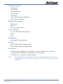
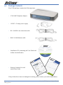
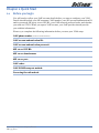
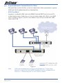
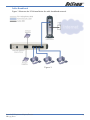
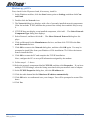
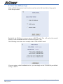
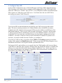
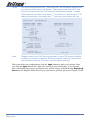
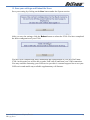
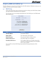
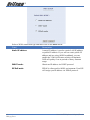
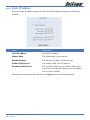
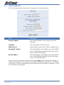
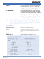
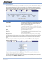
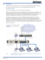
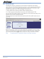
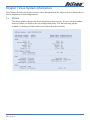
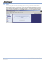
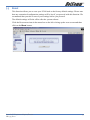
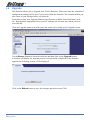
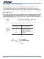
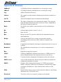
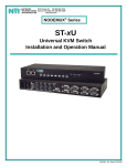
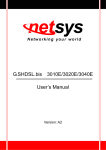
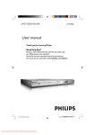
Contents
VoIP Telephone Adaptor/Router settings ................................................................. 4
Chapter 1 Introduction ......................................................................................... 5
1.1
Product Overview ...................................................................................... 5
1.2
Features ................................................................................................... 6
1.3
Application ............................................................................................... 8
1.4
System Minimum Requirements ................................................................... 9
1.5
Your Broadband Connection Bandwidth Consideration ..................................... 9
1.6
Package Contents .................................................................................... 10
1.7
Front Panel LED Indicators ........................................................................ 11
1.8
Back Panel and Wiring .............................................................................. 12
1.9
Power-up, Boot and Reset ......................................................................... 12
Chapter 2 Quick Start ........................................................................................ 13
2.1
Before you begin ..................................................................................... 13
2.2
Typical Network Connections for V200 ........................................................ 14
2.3
Installation ............................................................................................. 16
2.3.1 Cable Connections ................................................................................... 16
2.3.2 Power on your V200 and PC ...................................................................... 16
2.3.3 Connecting to V200 ................................................................................. 16
2.3.4 Configure the V200 via Web browser .......................................................... 19
Chapter 3 How to Log-in using a Web Browser....................................................... 24
3.1
V200 IP Address ...................................................................................... 24
3.2
Web Login .............................................................................................. 24
Chapter 4 WAN and LAN Set-up ........................................................................... 25
4.1
WAN Setup ............................................................................................. 25
4.1.1 Static IP address ..................................................................................... 27
4.1.2 DHCP Mode ............................................................................................ 28
4.1.3 PPPoE .................................................................................................... 29
4.2
LAN IP Address ....................................................................................... 30
Chapter 5 VoIP Setup ......................................................................................... 31
5.1
SIP ........................................................................................................ 31
5.1.1 Configuration .......................................................................................... 31
5.1.2 STUN ..................................................................................................... 35
5.1.3 Phone Book ............................................................................................ 36
5.1.4 Call Forward ........................................................................................... 37
5.1.5 Dial Plan ................................................................................................ 39
5.2
VoIP QoS ................................................................................................ 41
Chapter 6 Additional Routing Features .................................................................. 43
6.1
NAT Port Forwarding ................................................................................ 43
6.2
DMZ ...................................................................................................... 44
6.3
Access Control ........................................................................................ 45
6.4
Remote Access ........................................................................................ 46
Chapter 7 V200 System Information .................................................................... 47
7.1
Status .................................................................................................... 47
7.2
Traffic Statistics....................................................................................... 48
7.2.1 Interface Statistics................................................................................... 48
7.2.2 TCP-IP ................................................................................................... 49
2
YML795 Rev1
V200 VoIP Telephone Adaptor/Router
7.2.3 DHCP-Lease ............................................................................................ 50
7.3
Ping ....................................................................................................... 51
7.4
Save ...................................................................................................... 52
7.5
Reset ..................................................................................................... 53
7.6
Upgrade ................................................................................................. 54
7.7
Rebooting the System .............................................................................. 55
Appendix A: Cable Information ............................................................................ 56
Appendix B: Glossary ......................................................................................... 58
Appendix C: Registration and Warranty Information ............................................... 63
V200 VoIP Telephone Adaptor/Router
YML795 Rev1
3
VoIP Telephone Adaptor/Router settings
WEB account:
User Name:
admin
Password:
admin
LAN port IP:
192.168.30.1
4
YML795 Rev1
V200 VoIP Telephone Adaptor/Router
Chapter 1 Introduction
This chapter gives a brief introduction to the V200 VoIP Telephone Adaptor/Router, including a
product overview, description of the product features and its application.
1.1
Product Overview
The V200 has been designed for residential and small business users to deliver predictable
real-time voice quality over the Internet. It connects directly to any broadband modem and
service (Cable or DSL) which supports VoIP.
Two standard analogue telephones (desktop or cordless) can be connected to the Phone
(FXS) ports on the back of the V200, allowing the user to route calls over the Internet to
anywhere in the world using VoIP, significantly reducing or eliminating long distance call
charges.
To enhance your VoIP experience and simplify network integration, the V200 is equipped
with a 3-port Switch and Quality of Service (QoS) Router. The V200’s QoS feature ensures
you maintain high-quality VoIP calls during periods of heavy Internet use by dynamically
calculating and prioritising the required upstream bandwidth.
The V200 can be configured as a DHCP server for LAN and Network Address Translation
(NAT) can be used to translate private addresses to public address. In this way, computers in
the LAN do not require public IP addresses in order to access the Internet.
V200 VoIP Telephone Adaptor/Router
YML795 Rev1
5
1.2
Features
VoIP Protocol Support
•
Session Initiation Protocol (SIP)
•
Session Description Protocol (SDP)
•
Transport Protocol for Real-Time Applications (RTP)
VoIP Audio Codec
•
G.729a
•
G.711 alaw
•
G.711 ulaw
DTMF Relay
•
In-band
•
Out-band (RFC 2833)
Voice Features
•
Echo Cancellation (G.168)
•
Voice Activity Detection (VAD)
•
Comfort Noise Generation (CNG)
•
Silence Suppression
•
Jitter Buffer
•
Adjustable RTP packetization interval
Telephone Function Support
•
Caller ID (On/Off hook Caller ID ETSI based)
•
DTMF tone generation
•
Dial tone, Busy tone, Ring back tone generation
QoS
•
Internal bandwidth control
•
Allocating enough bandwidth for VoIP calls
VoIP Call types
•
SIP proxy
•
Phone Book for Peer-to-Peer IP Call
Built-in Router
•
DHCP client/server
•
NAT
•
Port Forwarding
•
DMZ
•
Virtual Server
6
YML795 Rev1
V200 VoIP Telephone Adaptor/Router
VoIP call functions *
•
Call Transfer
•
Call Waiting
•
Call Hold/Resume
•
Call Forward
•
Call Switch
•
CFU (Call Forward Unconditional)
•
CFB (Call Forward Busy)
WAN Protocol Support
•
DHCP client
•
Static IP
•
PPP over Ethernet client
Internet Support
•
IP, TCP, UDP, ICMP, ARP protocols
•
HTTP
•
DNS
VPN Support
•
IPSec and PPTP pass-through
Security
•
PAP/CHAP for PPPoE authentication
•
MD5 for SIP registration authentication
Device Ports
•
1 WAN port RJ-45 IEEE 802.3 10/100 Base-T, Auto-crossing for easy connection
•
3 LAN port RJ-45 IEEE 802.3 10/100 Base-T for LAN switch
•
2 FXS RJ-11 for connection to analog telephone
*Note:
The availability of some listed call features is dependent on the service
supported by your VoIP service provider. Please consult them for further
information.
V200 VoIP Telephone Adaptor/Router
YML795 Rev1
7
1.3
Application
Please refer to the following diagram for a typical application of the V200. Figure 1
illustrates a simplified connection for the V200. In addition to providing basic VoIP calls,
the V200 provides you with normal VoIP and router/switch capabilities, so it can work as a
router and a VoIP ATA (analog telephone adapter) at the same time.
Figure 1
8
YML795 Rev1
V200 VoIP Telephone Adaptor/Router
1.4
System Minimum Requirements
•
A valid SIP VoIP account from a VoIP Service Provider
•
A Broadband service
•
A Broadband Modem/Router (bridge-mode capable*)
•
An Analog telephone with RJ11 line cord (Desktop, Cordless or Dect.)
•
A PC with Web browsing application (for V200 configuration only)
*Note:
1.5
In some cases, you may need to configure your broadband router in
bridge-mode. The V200 will perform routing on your network.
Your Broadband Connection Bandwidth Consideration
In order to achieve good voice quality when using the V200 VoIP feature, we recommend
that you use the V200 on a broadband connection with an upstream speed of at least
128kpbs. This should allow you to have two simultaneous VoIP calls (with G.729 codec)
using the V200 with good voice quality**. The more bandwidth you have, the better the
quality.
**Note:
If your broadband router/modem handles the Internet traffic for your LAN
network, then the V200 voice quality might be affected when you are
in heavy Internet usage. If your router has QoS feature, please enable
and configure it to give V200 traffic high priority. V200 also has its QoS
feature, please see section 5.2 for instructions on how to use it.
V200 VoIP Telephone Adaptor/Router
YML795 Rev1
9
1.6
Package Contents
Your V200 package contains the following items:
•
V200 VoIP Telephone Adaptor
•
12VDC 1.5 Amps power supply
•
RJ-11 ADSL Line connection cable
•
RJ45 10/100 Ethernet cable
•
Installation CD (containing the User Guide and
Adobe Acrobat Reader)
•
Package Contents List and
Quick Start Guide
If any of the above items are damaged or missing, please contact your dealer immediately.
10
YML795 Rev1
V200 VoIP Telephone Adaptor/Router
1.7
Front Panel LED Indicators
LED Indicator
Status
Function
WAN
On
The WAN link is established
Off
Ethernet link for the WAN port is not established
Flash
Data transmitting or receiving over WAN
On
Ethernet link for LAN port is established
Off
Ethernet link for a LAN port is not established
Flash
Data transmitting or receiving over LAN
On
Phone is off-hook and being used
Off
Phone is not being used
Flash
VoIP call is coming
On
Power is supplied
Off
Power is not supplied
LAN 1 ~ LAN3
Phone1~2
POWER
V200 VoIP Telephone Adaptor/Router
YML795 Rev1
11
1.8
1.9
Back Panel and Wiring
Label
Description
Reset
Press button to restore the configuration to its factory
state.
WAN
Connect to your ADSL modem LAN port with an
RJ45 connector cable.
Phone 1 ~ 2
Connect to one or two phones with an RJ11
connector cable.
LAN
Connect to your PCs (Ethernet ports) or a hub/switch
with RJ45 connector cables.
Power
Connect to the power adapter and then plug the
power adapter into the wall outlet.
Power-up, Boot and Reset
Please only power up your V200 after all cables are connected. The POWER LED should
always be on after the V200 has powered up. Once the power is on, the V200 will boot up
automatically. Do not do anything until the boot up process has completed.
Boot or reboot
During the booting period, all of the LEDs, except for the POWER LED, will flash
irregularly. This is part of the normal process. All LEDs should be stabilized after the V200
has completely booted up (on, off or regular flashing). The whole booting procedure takes
about 1.5 minutes. Do not do anything to the V200 during the boot up, as this may cause
unexpected results or even damage the V200.
Reset
Reset reloads the V200 to its factory default settings. After the V200 has completely booted
up, use a small object - like a ballpoint pen to press the button and hold it down for over
three seconds. The V200 will reset and all its parameters will return to their factory default
settings. Then the V200 will reboot automatically. You can also reset the V200 in the Reset
menu of its Web configuration page.
12
YML795 Rev1
V200 VoIP Telephone Adaptor/Router
Chapter 2 Quick Start
2.1
Before you begin
You will need to collect your VoIP account details before you start to configure your V200.
Details should include your SIP username/ VoIP number, your SIP account authentication ID
and its password, SIP proxy server IP/URL, your VoIP network preferred codec and whether
you need use STUN. When you open a VoIP account, your VoIP provider should provide
you with this information.
Please try to complete the following information before you start your V200 setup:
VoIP phone number (also known as SIP username):
VoIP account authentication ID:
VoIP account authentication password:
SIP server IP/URL:
SIP server domain name:
SIP server port:
VoIP codec:
VoIP DTMF transport method:
Traversing firewall method:
V200 VoIP Telephone Adaptor/Router
YML795 Rev1
13
2.2
Typical Network Connections for V200
The Quick Start section will show you how to connect the V200 to your network. A typical
ADSL and cable broadband network are illustrated here.
ADSL Broadband
In general, a residential ADSL router runs PPPoE client and DHCP server for your PCs
to share Internet access. In this case, you can just simply connect the V200 to your ADSL
router as shown in Figure 2. Your PCs can connect to any LAN port in either the ADSL
router or the V200.
Figure 2
Note:
14
YML795 Rev1
V200 also has advanced routing and QoS features. To use these
features in conjunction with ADSL broadband service, please refer to
Section 4.1 WAN setup and 5.2 VoIP QoS for details.
V200 VoIP Telephone Adaptor/Router
Cable Broadband
Figure 3 illustrates the V200 installation for cable broadband network.
Figure 3
V200 VoIP Telephone Adaptor/Router
YML795 Rev1
15
2.3
Installation
2.3.1 Cable Connections
•
The Phone ports of the V200 are connected to a normal analog phone using a RJ11
cable.
•
The WAN port of the V200 is connected to your ADSL/Cable modem using a RJ45 cable.
•
A LAN port of the V200 is connected to your PC using a RJ45 cable.
2.3.2 Power on your V200 and PC
Make sure all cables are connected properly, and then power on the V200. It will take
approximately 1 to 2 minutes for the V200 to boot up.
After the V200 is completely booted up, switch on your PC which is directly connect to
V200 via its LAN port. This PC is only required for V200 configuration period.
2.3.3 Connecting to V200
The purpose of this section is to provide instructions on how to assign an IP address to your
PC. When the PC completely boots up, it might already be able to talk to the V200. You can
check it using “Ping” utility. If the connectivity is OK, you can skip this section and jump to
Section 2.3.4. This section are only required if you are having trouble accessing your V200.
HINT:
To test the network connectivity between the PC and the V200, you can
open a DOS prompt (Start ► Run ► cmd) and execute coming “ping
192.168.30.1”. Once you receive a reply from the V200 you know that
the PC and talk to the V200.
The Please ensure your PC is setup as DHCP client mode, in which the V200 will assign a
valid IP address to your PC and allow it can communicate with your V200. The following
section provides instructions on how to set this up with different Windows Operating
Systems.
Windows® XP PCs
1. In the Windows task bar, click the Start button, and then click Control Panel.
2. Click on Network & Internet Connections icon. (Category mode only).
3. Click the Network Connections icon.
4. In the LAN or High-Speed Internet window, right-click on the icon corresponding to
your network interface card (NIC) and select Properties. (Often, this icon is labelled
Local Area Connection).
5. The Local Area Connection dialog box displays with a list of currently installed network
items. Ensure that the check box to the left of the item labelled Internet Protocol (TCP/
IP) is checked. Select Internet Protocol TCP/IP and click on Properties.
6. In the Internet Protocol (TCP/IP) Properties dialog box, click the radio button labelled
Obtain an IP address automatically. Also click the radio button labelled Obtain DNS
server address automatically.
7. Click OK twice to confirm your changes, and close the Control Panel.
16
YML795 Rev1
V200 VoIP Telephone Adaptor/Router
Windows 2000 PCs
First, check for the IP protocol and, if necessary, install it:
1. In the Windows task bar, click the Start button, point to Settings, and then click Control Panel.
2. Double-click the Network and Dial-up Connections icon.
3. In the Network and Dial-up Connections window, right-click the Local Area Connection icon, and then select Properties.
4. In the Local Area Connection Properties dialog box, select Internet Protocol (TCP/IP),
and then click Properties
5. In the Internet Protocol (TCP/IP) Properties dialog box, click the radio button
labelled Obtain an IP address automatically. Also click the radio button labelled Obtain
DNS server address automatically.
6. Click OK twice to confirm and save your changes, and then close the Control Panel.
Windows Me PCs
1. In the Windows task bar, click the Start button, point to Settings, and then click Control Panel.
2. Click on View All Control Panel Options.
3. Double-click the Network icon.
4. The Network Properties dialog box displays with a list of currently installed network
components. If the list includes Internet Protocol (TCP/IP), then the protocol has already
been enabled. Skip to step 10.
5. If Internet Protocol (TCP/IP) does not display as an installed component, click Add…
6. In the Select Network Component Type dialog box, select Protocol, and then click
Add…
7. Select Microsoft in the Manufacturers box.
8. Select Internet Protocol (TCP/IP) in the Network Protocols list, and then click OK.
You may be prompted to install files from your Windows ME installation CD or other
media. Follow the instructions to install the files. If prompted, click OK to restart your
computer with the new settings.
Next, configure the PC to accept IP information assigned by the modem:
9. Follow steps 1 – 4 above..
10. In the Network Properties dialog box, select TCP/IP, and then click Properties.
If you have multiple TCP/IP listings, select the listing associated with your network card
or adapter.
11. In the TCP/IP Settings dialog box, click the radio button labelled Obtain an IP address automatically.
12. Click OK twice to confirm and save your changes, and then close the Control Panel.
V200 VoIP Telephone Adaptor/Router
YML795 Rev1
17
Windows 95, 98 PCs
First, check for the IP protocol and, if necessary, install it:
1. In the Windows task bar, click the Start button, point to Settings, and then click Control Panel.
2. Double-click the Network icon.
3. The Network dialog box displays with a list of currently installed network components.
If the list includes TCP/IP, and then the protocol has already been enabled. Skip to step
9.
4. If TCP/IP does not display as an installed component, click Add… The Select Network
Component Type dialog box displays.
5. Select Protocol, and then click Add… The Select Network Protocol dialog box displays.
6. Click on Microsoft in the Manufacturers list box, and then click TCP/IP in the Network Protocols list box.
7. Click OK to return to the Network dialog box, and then click OK again. You may be
prompted to install files from your Windows 95/98 installation CD. Follow the instructions to install the files.
8. Click OK to restart the PC and complete the TCP/IP installation.
Next, configure the PCs to accept IP information assigned by the modem:
9. Follow steps 1 – 3 above.
10. Select the network component labelled TCP/IP, and then click Properties. If you have
multiple TCP/IP listings, select the listing associated with your network card or adapter.
11. In the TCP/IP Properties dialog box, click the IP Address tab.
12. Click the radio button labelled Obtain an IP address automatically.
13. Click OK twice to confirm and save your changes. You will be prompted to restart Windows.
14. Click Yes.
18
YML795 Rev1
V200 VoIP Telephone Adaptor/Router
2.3.4 Configure the V200 via Web browser
This section describes how to logon and configure the V200 via a Web browser from your
PC, which should be directly connected to the V200 via its LAN port.
A. Logon to your V200
Open your Web browser (IE or Netscape) and type 192.168.30.1 in its address bar. You will
see the login window. A unique default user account is assigned with user name admin and
password admin.
After you have logged in to the V200, you will be presented with the V200 Status page.
V200 VoIP Telephone Adaptor/Router
YML795 Rev1
19
B. Select V200 WAN port type
Click on WAN Setup menu item from the menu bar on the left hand side to bring up the
WAN Setup window:
By default, the WAN port is setup to operate in DHCP mode. This will work with a typical
ADSL or cable broadband network as shown in Figures 2 & 3.
The following screen shot is an example of the V200 in DHCP mode.
If you are using a cable broadband service, you can simply use the V200 WAN port default
setting as DHCP.
20
YML795 Rev1
V200 VoIP Telephone Adaptor/Router
C. Configure V200 SIP
On the V200 Configuration page, click the SIP button will bring a SIP configuration page.
The following screen shows you an example of SIP configuration of the V200 which will
allow the V200 to use “630801” and “683752” as its VoIP phone number and authentication
ID to register on “fwd.pulver.com” SIP server. It will also show the use of STUN for
traversing your router’s NAT/Firewall.
Type in your SIP account information provided by your VoIP service provider in this
page. The most common parameters are: Phone Number (also called SIP user name),
Authentication ID, Authentication password, SIP proxy host Address and SIP proxy Port
and Domain address. There are two VoIP accounts in this page - Account 1 and Account
2, which represent Phone1 and Phone2 respectively. By default the Phone 2 (Account 2)
is disabled. So if you only have one SIP account, you can simply configure the account
in Phone 1 (Account 1) and leave the Account 2 disabled as its default. If you have two
accounts, you need to enable Account 2 before you configure it.
If you have a VoIP account, you need to choose YES in the UseProxy option (the default
setting of this option is in Non-Proxy mode). Then you can input SIP Proxy/Register server
information and let the V200 register with the specified SIP server.
The Internal Call* option allows you to specify how the V200 handles calls between Phone
1 and Phone 2 when they have separate VoIP accounts. By default this feature is enabled and
allows you to route the calls locally between Phone1 and Phone 2 (i.e. In this case there is
no traffic going through to the Internet). If disabled, calls between Phone1 and Phone2 will
be routed by your VoIP providers’ SIP server.
V200 VoIP Telephone Adaptor/Router
YML795 Rev1
21
*Note:
You must configure Account 1 and Account 2 on the above page before
you can use the internal call feature. That means both Account 1 and
Account 2 need to have a VoIP account information entered. In terms
of the internal call, there is an alias “**” for Account 1 and Account 2. To
make internal calls, just simply dial “**” and the other phone will ring.
Note:
Please consult your VoIP service provider for your SIP account details,
whether you need to configure STUN and which codec you should use
and its packet interval. If unsure, use the default settings.
When you finish your configuration, click the Apply button to apply your settings. Once
you click the Apply button, the V200 will return you to the Status page. A few seconds
later, refresh this page using your Web browser refresh button; it should display Registered
Success in the Register Status field. If you experience a problem, please see Chapter 5 VoIP.
22
YML795 Rev1
V200 VoIP Telephone Adaptor/Router
D. Save your settings and Reboot the V200
Save your setting by clicking on the Save button under the System section
After you save the settings, click the Reboot button to reboot the V200. You have completed
the basic configuration of your V200.
You have now completed the basic installation and configuration of your new NetComm
V200. At this point you will be able to make VoIP calls to and from your V200 connection.
You may consider contacting your VoIP service provider’s customer support line to test your
VoIP service and enable any available supplementary call features.
V200 VoIP Telephone Adaptor/Router
YML795 Rev1
23
Chapter 3 How to Log-in using a Web Browser
This chapter describes how to manage the V200 via a Web browser from a PC directly connected to
the V200. You can use a web browser such as Microsoft Internet Explorer, Netscape Navigator or
Mozilla Firefox. A default user account is assigned with user name admin and password admin. You
can change the default password later after logging on to the device.
3.1
V200 IP Address
To log on to the V200 using a web browser, your PC and the V200 should both be on the
same network segment. The default IP address for the V200 is 192.168.30.1. If your PC is
not on the same network segment, you can modify its IP address or change its IP address
assignment to DHCP mode so that the V200 can assign a valid LAN IP address to your PC.
Note:
3.2
If you have already completed the Quick Start section and successfully
connected your PC and the V200, you can skip this section and proceed
directly to “3.2 Web Login”.
Web Login
Open a Web browser and type 192.168.30.1 in its address bar. You will see the login
window.
Enter your user name and password then click OK. The following V200 Status window
is an example of what will be displayed. The contents of this page are explained in the
chapters 4 and 5.
24
YML795 Rev1
V200 VoIP Telephone Adaptor/Router
Chapter 4 WAN and LAN Set-up
The Basic Menu tab is located on the left hand side of the Web interface. With these screens you can
configure the WAN and LAN interface settings.
4.1
WAN Setup
Click on the WAN Setup menu item from the menu bar to bring up the WAN Status window.
The WAN IP address information will be displayed.
The following screen is an example which shows the V200’s WAN port is in PPPoE mode
and currently active.
Field
Description
WAN IP address
The WAN IP address.
Subnet Mask
The subnet mask of this network.
Default Gateway
The gateway IP address of this network.
Primary DNS Server
The primary DNS server IP address.
Secondary DNS Server
The secondary DNS server IP address that will be
used in the event that the primary server IP address
fails or is not available.
To set up WAN, click the WAN Setup button and the following information will be
displayed:
V200 VoIP Telephone Adaptor/Router
YML795 Rev1
25
Select a WAN connection type and then click on the Next button.
Field
Description
Static IP address:
A static IP address, it can be a static LAN IP address
or public IP address. If you will use static public IP
address and are using ADSL broadband, you can
enable the V200 QoS feature which will maintain
VoIP call quality even in periods of heavy Internet
usage.
DHCP mode:
Obtain an IP address via DHCP protocol.
PPPoE mode:
PPPoE is often used in ADSL environment. Your ISP
will assign you IP address via PPPoE protocol.
26
YML795 Rev1
V200 VoIP Telephone Adaptor/Router
4.1.1 Static IP address
Select the Static IP address option and click on the Next button to display the following
window.
Field
Description
WAN IP address
The WAN IP address.
Subnet Mask
The subnet mask of this network.
Default Gateway
The gateway IP address of this network.
Primary DNS Server
The primary DNS server IP address.
Secondary DNS Server
The secondary DNS server IP address that will be
used in the event that the primary server IP address
fails or is not available.
Enter the necessary parameters and click the Apply button to submit the settings.
V200 VoIP Telephone Adaptor/Router
YML795 Rev1
27
4.1.2 DHCP Mode
Select the DHCP Mode option and click on the Next button to display the following
window:
Click the YES button to enable your V200 as a DHCP client.
28
YML795 Rev1
V200 VoIP Telephone Adaptor/Router
4.1.3 PPPoE
When using PPPoE, the V200 will assign you an IP address via PPPoE protocol from your
ISP. When WAN port is set in PPPoE mode, the V200 will do routing for your network
and you are able to enable its QoS feature. Please see Section 5.2 for details about cable
connection of the V200 and your ADSL modem/router and its WAN mode.
Select the PPPoE mode option and click on the Next button to display the following
window.
Field
Description
User name
PPPoE account username. This is not your VoIP
number. This username is issued by your ISP.
Password
PPPoE account password. This is not your VoIP
password. This password is issued by your ISP.
Confirm Password
Same as Password.
Enter your Username, Password and Confirm password then click the Apply button to
summit the settings.
V200 VoIP Telephone Adaptor/Router
YML795 Rev1
29
4.2
LAN IP Address
Click LAN Setup from the menu bar to bring up the LAN Setup window:
Field
Description
LAN IP Address
The unique IP address of the V200 on the LAN
network.
NetMask
The subnet mask of the IP network.
DHCP Server
Select Enable if you use the V200 as a DHCP server.
Starting IP Address
The first IP address of the address pool in the DHCP
server. The IP address should be in the same subnet
as the V200 LAN IP address.
End IP Address
The last IP address of the address pool in the DHCP
server. The IP address should be in the same subnet
as the V200 LAN IP address.
Enter or select the parameters and then click on the Apply button to submit the settings. A
confirmation window will be displayed. Click Yes to confirm the submission or click No to
cancel them. The Web configuration will be interrupted if the IP address is changed. Use the
new IP address to login again.
30
YML795 Rev1
V200 VoIP Telephone Adaptor/Router
Chapter 5 VoIP Setup
5.1
SIP
The Session Initiation Protocol (SIP) is an Internet Engineering Task Force (IETF) standard
protocol for initiating an interactive user session that involves multimedia elements such as
video, voice, chat, gaming, and virtual reality.
The SIP is a request-response protocol, dealing with requests from clients and responses
from servers. It can establish multimedia sessions or Internet telephony calls, and modify or
terminate them. Because the SIP supports name mapping and redirection services, it makes
it possible for users to initiate and receive communications and services from any location,
and for networks to identify the users wherever they are.
5.1.1 Configuration
You can configure SIP parameters in Configuration window. The figure below shows you an
example of a SIP account configuration.
There are two VoIP accounts in this page - Account 1 and Account 2, which represent
Phone1 and Phone2 respectively. By default the Phone 2 (Account 2) is disabled. So if you
only have one SIP account, you can simply configure the account in Phone 1 (Account 1)
and leave the Account 2 disabled as its default. If you have two accounts, you need to enable
Account 2 before you configure it.
Field
Description
Client
Phone Number
The phone number used for your V200 to register on
a SIP server.
Display Name
What the call party see when you call them.
V200 VoIP Telephone Adaptor/Router
YML795 Rev1
31
Field
Description
Auth ID
The authentication username assigned by your VoIP
service provider. This can be a different number to
your VoIP number.
Auth Password
The authentication password assigned by your VoIP
service provider.
Confirm Password
Repeat the password.
Expire
Duration of interval for SIP keep alive registration.
Default 60.
QValue
The priority assigned to the V200 to register on the
SIP server of your VoIP service provider. The value
must be between 0 and 1, with 1 having the highest
priority. Default 0.8.
RTP packet interval
Duration (frequency) of the V200 sending
compressed voice data packet. There are two options
for this setting 20ms and 40ms. In some cases, a
40ms interval can save your broadband upstream
bandwidth comparable to a 20ms interval. For the
best value for this setting, please consult your VoIP
service provider.
Codec
G.729 is the highest compression codec which
only occupies 8kbits/sec. PCMA (G.711 alaw) and
PCMU (G.711 ulaw) quire 64kbits/sec. We highly
recommended you to use G.729. Default G.729.
DTMF
In-band or RFC 2833. Default in-band.
Payload Type
It indicates which RTP packets contain DTMF
information in normal RTP stream.
MaxDigist
The maximum number of digits (numbers) you can
dial using the V200. Default 24.
MaxRings
The number of rings before an incoming call is
answered. Maximum 24. Default 15.
Port No
The port on the host used to communicate with the
SIP server or remote end. This port can be changed.
Default 5060.
UseProxy
In order to use the V200 with a VoIP service provider
you will need to specify a Proxy server which the
V200 communicates with. Choose Yes and enter
the details under the Proxy/Register and Domain
sections. Choose No if you want to use the V200 in
Peer-to-Peer mode.
32
YML795 Rev1
V200 VoIP Telephone Adaptor/Router
Field
Description
RTP Port
The base RTP port of V200. The real range of V200
RTP port is Base Port ~ Base Port +7 (8 ports in
total). For example, by specifying 16384 here, the
real RTP port range will be 16384 ~ 16391.
The Internal Call*
The Internal Call option allows you to specify how
the V200 handles calls between Phone 1 and Phone
2 when they have separate VoIP accounts. By default
this feature is enabled and allows you to route the
calls locally between Phone1 and Phone 2 (In this
case there is no traffic going through to the Internet).
If disabled, calls between Phone1 and Phone2 will be
routed by your VoIP providers’ SIP server.
*Note:
You must configure Account 1 and Account 2 before you can use the
internal call feature. That means both Account 1 and Account 2 need to
have a VoIP account information entered. In terms of the internal call,
there is an alias “**” for Account 1 and Account 2. To make internal calls,
just simply dial “**” and the other phone will ring.
Proxy/Register
Host Address/URL
IP address of the SIP proxy server.
Port No
Port number of the SIP-Proxy server, at which it
listens to your VoIP signalling messages. Default
5060.
Domain
Domain Address
V200 VoIP Telephone Adaptor/Router
YML795 Rev1
Domain name of the SIP Registrar server.
33
Enter or select the required information and then click on the Apply button to submit the
settings. The system status window will be opened.
The SIP registration status is displayed in the top-right hand corner. It will take a while to
complete the registration process. Use the Refresh button on your web browser to check the
registration status.
Field
Description
Register Status:
There are three instances as explained in the
following:
DIRECT_CALL will be displayed all the time if you
choose non-UseProxy mode.
Not Registered will be displayed if you configure
the V200 in UseProxy mode, but fail to register.
Registered Success will be displayed if you choose
UseProxy mode and registered successfully.
VoIP Phone number, Client, Proxy/Register/Domain, WAN and STUN display their related
information.
34
YML795 Rev1
V200 VoIP Telephone Adaptor/Router
5.1.2 STUN
STUN stands for Simple Traversal of UDP over NAT. It is a protocol which enables the
V200 to detect the presence and type of NAT behind which the phone is placed. STUN will
allow SIP signalling and bi-direction to successfully traverse a NAT without requiring any
configuration changes on the NAT.
Select Enable or Disabled, enter all the information if Enable is selected, and then click on
the Modify button to apply the new settings.
Field
Description
STUN IP or Domain Name
The IP address or domain name of the STUN server,
which could be provided by your service provider, or
a free STUN server on the Internet.
STUN type
This column is Read Only. The STUN mechanism
will identify your NAT type and display it on the
screen.
Port No
Port number of the STUN server where the server
listens to your STUN client requests. Default 3478.
V200 VoIP Telephone Adaptor/Router
YML795 Rev1
35
5.1.3 Phone Book
The Phone Book should only be used in SIP non-use Proxy mode. With the Phone Book you
do not need to subscribe to a VoIP service provider. You will need to obtain the public IP
address and SIP outbound address port of the SIP phone or ATA you wish to communicate
with. The first page displays the current phone list. Below is a typical example.
Field
Description
User Name
User name of the person (e.g. Kirstin) that you want
to reach. And the remote party must use this user
name to accept incoming call.
Speed Dial
A speed dial number. Whenever dialling 123 using
your V200 you will be connecting to the Destination
IP address on the specified port.
Host
The host IP address to call.
Port No
The port number on which destination party listens
your V200 SIP requests.
Display Name
The name displayed to the person you are calling.
You will need to ask the person you are calling to configure their Internet device (Modem/
Router) to allow connections on the specified port to be forwarded to their SIP phone or
ATA.
To add a new phone number to the phone book, click the Add button. The Add phone
number window is opened:
Enter the information and click the Add button. You will be returned to the phone list
window with the added number now displayed.
You can also modify or delete any entry by selecting the corresponding Select option and
then clicking on the Modify or Delete buttons.
36
YML795 Rev1
V200 VoIP Telephone Adaptor/Router
5.1.4 Call Forward
Call Forward lists the configured call forward information. The first page displays the
current call forward list. The V200 has two call forwarding entries, which allows you to
specify call forwarding for each SIP account.
To modify the call forward list, select the corresponding Select option and then click on the
Modify button. The Modify Call Forward window is opened.
Field
Description
Fwd Call
Choose YES if you want calls to be forwarded.
Choose NO if you do not want calls to be forwarded.
User Name
SIP user name (VoIP number) to which calls will be
forwarded to (e.g.09100308).
Host Addr or Domain Name
If you use the V200 in SIP proxy mode, this is
the Domain name in which your V200 currently
registers. If you use V200 in Non-Proxy mode, this
is the IP address of the forward-to VoIP ATA or IP
phone.
Port No
The port number at which the remote ATA/IP phone
or SIP server listen SIP request. Default: 5060
Fwd Uncond
If you choose Yes, incoming calls will be forwarded
to the specified number without ringing on your VoIP
phone. If you choose No, your VoIP phone will ring
the specific number of times before being forwarded
to the number above.
Fwd Rings
The specified number of rings before Unconditional
call forwarding happens.
V200 VoIP Telephone Adaptor/Router
YML795 Rev1
37
Enter the information and click on the Modify button. You will be returned to the Call
Forward List window with the modified details now displayed.
You also can delete any entry from the call forward list by selecting the corresponding
Select option and clicking on the Delete button.
In the V200’s default state, there are no entries for this window, so the Add button is
displayed, instead of the Modify button. Use the Add button to add the list.
38
YML795 Rev1
V200 VoIP Telephone Adaptor/Router
5.1.5 Dial Plan
Dial Plan can make your dialling easier. If the dialled number meets the Prefix, the V200
will modify the dialled number before dialling it. If the dialled number does not meet the
Prefix, the V200 will dial the number without any modification.
The first page displays current dial plan:
To add a new entry in the Dial Plan, click the Add button. The Add Dial Plan window is
opened:
Field
Description
Prefix
The prefix number that needs to be modified for Dial
Plan.
Mini_digit
Minimum length of the dialled number, that must be
equal to or greater than the Prefix number.
Max_digit
Maximum length of the dialled number. If the length
of the dialled number is greater than this value, the
digits over this value will be eliminated.
Delete_digit
The number of digits that need to be eliminated
before dialling. The eliminated digits begin at the
first digit of the dialled number.
Insert_digit
The digits that need to replace the deleted number.
Above window shows Kirstin’s first dialling method in her Dial Plan. Kirstin just come
Australia from UK. The international call number in UK is “00”. With the V200, she does
not have to change it into “0011”. In above dial plan configuration, whenever she dials
00XXYYYYYY, the output is 0011XXYYYYYY. So she can keep her dialling habit as she
is dialling overseas in UK.
V200 VoIP Telephone Adaptor/Router
YML795 Rev1
39
Enter the information and click the Add button. You will be returned to the Dial Plan list
window with the added plan now displayed.
You also can modify or delete any specific method from the Dial Plan by selecting the
corresponding Select option and clicking on the Modify or Delete button.
40
YML795 Rev1
V200 VoIP Telephone Adaptor/Router
5.2
VoIP QoS
VoIP QoS is a function that allows users to keep enough bandwidth for VoIP calls during
heavy Internet usage periods; hence it can maintain high-quality VoIP calls.
Conditions of QoS
There are two conditions to use the V200 QoS feature properly.
Firstly, your broadband Internet connection should have a fixed upstream bandwidth. Cable
broadband Internet services share a fixed bandwidth and therefore do not have a fixed
upstream bandwidth for their Internet access. In contrast, ADSL users normally have a fixed
upstream bandwidth, which should be stated in their ADSL service plan contract.
Secondly, you will need to let your V200 to handle the Internet traffic for your LAN
network. We recommend you install your V200 based on the following network diagram
which will let the V200 QoS work properly. If you have already had an ADSL router
working, you will need to reconfigure your ADSL router into bridge mode in order to use the
QoS feature (Please refer to the User Manual of your ADSL modem/router for instructions
on how to set this up).
Note:
The WAN port mode in this diagram can be either in PPPoE or Static IP
(assign a public IP) mode.
V200 VoIP Telephone Adaptor/Router
YML795 Rev1
41
Routing Internet Traffic for your LAN Network
When your V200 WAN interface is assigned with a Public IP either through static WAN IP
or PPPoE, it actually does the routing for your Internet connection. When you configure
QoS, you need to specify your ADSL true upstream bandwidth. It might be 64, 128, 256
or 512. If you are not sure about this parameter, please consult your ADSL Internet service
provider.
Click VoIP QoS in the menu bar to bring up the QoS configuration window:
The link speed of Up Stream is in the unit of Kbps, type in your ADSL true upstream speed
value and click on the Apply button to submit the settings. That’s all, there is to it. QoS for
VoIP calls is now enabled.
42
YML795 Rev1
V200 VoIP Telephone Adaptor/Router
Chapter 6 Additional Routing Features
This chapter describes the use and configuration of the additional Routing features supported by the
V200.
6.1
NAT Port Forwarding
Port forwarding is the action of forwarding network ports on the WAN interface to PCs or
servers in LAN network. Virtual servers use this technique to allow external users (in most
cases via the Internet) to reach services provided by internal servers such as FTP, HTTP,
Telnet, etc. The V200 has the capability to perform port forwarding.
Click the NAT Port Forward menu item in the menu bar on the left to display the current
port forward setting.
Field
Description
Public Port From /Public Port To Type in the public port for remote user accessing.
The category is 1-65535.
Protocol
TCP or UDP.
Local Address
Type in the local IP address
Local Port From/Local Port To
Type in the Local Port.
You can add a new entry using the Add button, or delete an entry by selecting the
corresponding Select option and clicking on the Delete button
V200 VoIP Telephone Adaptor/Router
YML795 Rev1
43
6.2 DMZ
A DMZ allows a single computer on your LAN to expose ALL of its ports to the Internet.
By doing this, the exposed computer is no longer ‘behind’ the NAT/firewall. DMZ is far
easier to set up than port forwarding in terms of setting up a virtual server, but it exposes
your entire computer to the Internet.
Note:
Sometimes TCP/IP applications require very specialized IP
configurations that are difficult to set up. In this case, placing your
computer in the DMZ is the only way to get the application working.
Following is an example of DMZ, which redirects all of low ports on WAN
interface to a host with internal IP address 192.168.30.143.
Click the DMZ menu item in the menu bar on the left to display the current DMZ
configuration setting.
You can decide to Enable or Disable DMZ. Enter the internal IP address if DMZ is enabled.
Then click the Apply button to submit the setting.
44
YML795 Rev1
V200 VoIP Telephone Adaptor/Router
6.3
Access Control
You can change your password in this menu.
Click the Access Control menu item in the menu bar on the left to change your password for
the V200’s Web log-in.
Type the old password and then type the new password twice. Click on the Apply button to
submit the settings.
Note:
If you change the password, make sure you keep a record of it in a safe
place, as you will require it the next time you log-on.
V200 VoIP Telephone Adaptor/Router
YML795 Rev1
45
6.4 Remote Access
To manage the V200 via a web browser you do not have to login from a PC directly
connected to the V200. With the Remote Access feature, you can login through the Internet
from anywhere if you know the public WAN IP address of the V200. This feature is only
available if you connect your V200 and configure your network in:
1) Basic ADSL Router connection with the Router in Bridge mode or
2) A Cable connection with no Router between the cable modem and the V200.
Just type in the WAN public IP address in the address bar of your web browser and you can
login into V200 remotely through the Internet.
Click the Remote Access menu item in the menu bar on the left to enable remote access to
your V200.
Remote Access feature can put your V200 at risk because an intruder can access it in the
same way. This menu gives you the option to Enable or Disable this feature. Simply make
your selection then click the Apply button to submit the setting. The default is Disable.
Note:
46
YML795 Rev1
It is good practice to enable this feature only when necessary.
V200 VoIP Telephone Adaptor/Router
Chapter 7 V200 System Information
This Chapter describes the System section, where information on the whole system is displayed or is
used to implement certain configurations.
7.1
Status
The Status window displays the basic information of the system. It is also the first window
displayed when you login to the web configuration utility. You also can bring up this
window by clicking on Status menu item on the left in the menu bar:
V200 VoIP Telephone Adaptor/Router
YML795 Rev1
47
7.2
Traffic Statistics
The Traffic Statistics menu will display detailed information on the V200’s LAN & WAN
Interface, TCP-IP settings and DHCP client leased information.
7.2.1 Interface Statistics
Interfaces is the first page of the Traffic Statistics window.
Interface Name
Name of the interface
Admin Status
Indicates whether the interface is Up or Down.
Octets In
Number of Octets (bytes) received.
Unicast PktsIn
Number of unicast packets received.
Broadcast PktsIn
Number of broadcast packets received.
Discards In
Number of packets received that were discarded.
Errors In
Number of inward errors.
Octets Out
Number of Octets (bytes) transmitted.
Unicast PktsOut
Number of unicast packets transmitted.
Broadcast PktsOut
Number of broadcast packets transmitted.
Discards Out
Number of packets transmitted that were discarded.
Errors Out
Number of outward errors.
48
YML795 Rev1
V200 VoIP Telephone Adaptor/Router
7.2.2 TCP-IP
The TCP-IP page displays the IP statistics, UDP statistics, TCP statistics, and ICMP
statistics.
V200 VoIP Telephone Adaptor/Router
YML795 Rev1
49
7.2.3 DHCP-Lease
DHCP-Lease page displays information regarding MAC Address mapping to Lease-IP.
50
YML795 Rev1
V200 VoIP Telephone Adaptor/Router
7.3
Ping
A Ping test is used to verify the status of a network connection. Ping sends a request
message to the host and waits for a return message. This function can verify if the remote
host is reachable. Ping can also measure the round-trip time to the remote host.
Click the Ping menu item in the menu bar on the left to bring up the Ping screen.
Enter the Host Name or IP address of the remote terminal and click on the Submit button to
start the ping. The results are displayed. The following is an example of the ping result:
Field
Description
Packets transmitted
Number of packets that were transmitted.
Packets received
Number of packets that were received.
Packets loss (%)
Number of packets lost (transmitted-received)
Minimum round trip time
The fastest round-trip time.
Maximum round trip time
The slowest round-trip time.
V200 VoIP Telephone Adaptor/Router
YML795 Rev1
51
7.4
Save
A new setting will take effect immediately after the setting is submitted. If the V200 is
powered down, however, it will be lost. To keep your new settings permanently, you need
to save them into flash memory by using the Save menu. Click the Save menu item in the
menu bar on the left and then click on the Save button to save your configuration settings.
52
YML795 Rev1
V200 VoIP Telephone Adaptor/Router
7.5
Reset
This function allows you to reset your V200 back to the factory default settings. Please note
that any customised configuration settings will be lost if you proceed with this function. We
recommend that you take a note of your settings before you proceed.
The default settings will take effect after the system reboots.
Click the Reset menu item in the menu bar on the left to bring up the reset screen and then
click on the Reset button.
V200 VoIP Telephone Adaptor/Router
YML795 Rev1
53
7.6
Upgrade
This function allows you to Upgrade your V200’s firmware. Please note that any customised
configuration settings will be lost if you proceed with this function. We recommend that you
take a note of your settings before you proceed.
From time to time, new Upgrade firmware may become available from NetComm’s web
site. Download the appropriate file to your PC and note the location into which you have
saved the file.
Click the Upgrade menu item in the menu bar on the left to bring up the Upgrade screen.
Use the Browse button to locate the software and then click on the Upgrade button.
A window will display the upgrade process. On successful completion of the firmware
upgrade, the following screen will be displayed.
Click on the Reboot button to save the changes and reboot your V200.
54
YML795 Rev1
V200 VoIP Telephone Adaptor/Router
7.7
Rebooting the System
It may be necessary to reboot the V200. Ensure that you have saved any changes to the
system setting of the V200. Please note that any customised configuration settings will be
lost if you proceed with this function without saving the changes (refer to the section on the
Save menu).
Click the Reboot menu item in the menu bar on the left to bring up the Reboot screen. Click
on the Reboot button to reboot the V200.
V200 VoIP Telephone Adaptor/Router
YML795 Rev1
55
Appendix A: Cable Information
This cable information is provided for your reference only. Please ensure you only connect the
appropriate cable into the correct socket on either this product or your computer.
If you are unsure about which cable to use or which socket to connect it to, please refer to the
hardware installation section in this manual. If you are still not sure about cable connections, please
contact a professional computer technician or NetComm for further advice.
RJ-45 Network Ports
RJ-45 Network Ports can connect any networking devices that use a standard LAN interface, such as
a Hub/Switch Hub or Router. Use unshielded twisted-pair (UTP) or shield twisted-pair (STP) cable
to connect the networking device to the RJ-45 Ethernet port. Depending on the type of connection,
10Mbps or 100Mbps, use the following Ethernet cable, as prescribed.
10Mbps:
Use EIA/TIA-568-100-Category 3, 4 or 5 cable.
100Mbps:
Use EIA/TIA-568-100-Category 5 cable.
Note:
To prevent loss of signal, make sure that the length of any twisted-pair
connection does not exceed 100 metres.
RJ-45 Connector
Pin Assignment
1
2
3
6
4,5,7,8
Normal Assignment
Input Receive Data +
Input Receive Data Output Transmit Data +
Output Transmit Data Not used
Figure 1
RJ-45 plug
attached to cable
Figure 2
56
YML795 Rev1
V200 VoIP Telephone Adaptor/Router
Straight and crossover cable configuration
There are two types of the wiring: Straight-Through Cables and Crossover Cables. Category 5 UTP/
STP cable has eight wires inside the sheath. The wires form four pairs. Straight-Through Cables has
same pinouts at both ends while Crossover Cables has a different pin arrangement at each end.
In a straight-through cable, wires 1,2,3,4,5,6,7 and 8 at one end of the cable are still wires 1~8 at the
other end. In a crossover cable, the wires of 1,2,3,6 are reversed so that wire 1 become 3 at the other
end of the cable, 2 becomes 6, and so forth.
To determine which wire is wire 1, hold the RJ-45 cable tip with the spring clip facing towards the
ground and the end pointing away from you. The copper wires exposed upwards to your view. The
first wire on the far left is wire 1. You can also refer to the illustrations and charts of the internal
wiring on the following page.
Straight-Through Cabling
Figure 3
Wire
1
2
3
6
Becomes
1
2
3
6
Cross-Over Cabling
Figure 4
Wire
1
2
3
6
Note:
Becomes
3
6
1
2
To prevent loss of signal, make sure that the length of any twisted-pair
connection does not exceed 100 metres.
V200 VoIP Telephone Adaptor/Router
YML795 Rev1
57
Appendix B: Glossary
100BaseT:
A 100 Mbps Ethernet standard that uses twisted-pair wiring.
10BaseT:
A 10 Mbps Ethernet standard that uses twisted-pair wiring.
Arp:
Address Resolution Protocol
Address:
The symbol (usually numeric) identifying an interface attached to a
network.
ASCII:
American Standard Code for Information Interchange.
Bandwidth:
The range of frequencies of a transmission channel. The wider the
range the higher the data rate that can be sent. Hence, bandwidth is
also taken to mean the data rate.
Baud:
One baud is one symbol (state-transition or level-transition) per
second.
Bit:
A binary digit, with the value of –0 or –1.
Boot:
Start a device.
Bps:
Bits per second. The speed at which bits are transmitted across a
data connection.
Bridge:
A device that links local or remote area networks together,
forwarding packets based on a MAC address (compare with
gateway).
Broadband:
Communication channels operating at transmission rates in excess of
64 Kbps.
Broadcast:
The simultaneous transmission to two or more communication
devices.
Byte:
Eight bits arranged in sequence
CHAP:
Challenge-Handshake Authentication Protocol. A PPP protocol to
ensure authentication of the connection between two devices.
CPE:
Customer Premises Equipment. Equipment used by the end-user.
DHCP server:
A server that dynamically allocates network addresses and delivers
configuration parameters to hosts.
DHCP:
Dynamic Host Configuration Protocol. A TCP/IP protocol that
enables a network connected to the Internet to automatically assign
a temporary IP address to a host when the host connects to the
network.
DNS:
Domain Name Server. A server that retains the addresses and routing
information for TCP/IP PAT users.
Download:
To receive a file over a network (compare with upload).
58
YML795 Rev1
V200 VoIP Telephone Adaptor/Router
DSP:
Digital Signal Processor. The microprocessor that handles line
signaling in a modem.
DTE:
Data Terminal Equipment. Equipment that transmits or receives data
in the form of digital signals.
Dynamic detection:
A process of a automatic detection of a new device added or
removed from the PC.
Ethernet address:
Another name for MAC address.
Ethernet:
A standard protocol (IEEE 802.3) for a 10-Mb/s baseband local area
network (PAT) bus that supports high-speed communication among
systems. It operates at the Physical Layer of the OSI Model.
ETSI:
European Telecommunications Standards Institute.
Firmware:
Software that has been temporarily or permanently loaded into
ROM.
Flash memory:
A type of RAM that retains its information, even after poweringdown.
FTP:
File Transfer Protocol. A TCP/IP standard protocol for transferring
files
Gateway:
A communications device that connects two different networks.
Header:
The beginning of a frame or cell that contains management and
addressing information.
Hop:
One point-to-point transmission in a series required to transmit a
message between two hosts in a network.
Host:
An addressable computer connected to a network.
Hub:
A device that serves as the central location for attaching wires form
workstations.
H.323:
The ITU (International Telecommunication Union) standard, which
defines how audio-visual conferencing data is sent across any packet
network.
ICMP:
Internet Control Management Protocol. An Internet protocol that
allows for the generation of error messages, tests packets, and
information messages related to IP.
IEEE:
Institute of Electrical and Electronics Engineers.
IEEE:
The Institute of Electrical and Electronics Engineers.
IP address:
Internet Protocol address. The decimal-numeric, fixed-length address
assigned to an Internet host.
IRQ:
Interrupt re-quest, a hardware interrupt on a PC.
ISO:
International Standards Organization.
V200 VoIP Telephone Adaptor/Router
YML795 Rev1
59
ISP:
Internet Service Provider. An organization that provides access to the
Internet.
Kbps:
Literally it means Kilobits per second, but usually it is taken to mean
1,024 bits per second.
LAN:
Local Area Network. A LAN is a data communications system that
lies within a limited spatial area, has a specific user group, and has a
specific topology.
LED:
Light Emitting Diode. A light or status indicator.
MAC address:
Media Access Control address. The unique fixed address of a piece
of hardware, normally set at the time of manufacture and used in
PAT protocols.
MAC:
Medium Access Control, a protocol for determining which device
has access to the network at any one time.
Mbps:
Megabits per second. One megabit is 1,048,576 (10242) bits.
MGCP:
Media Gateway Control Protocol, is a protocol used within a VoIP
system.
NAT:
Network Address Translation is a transparent routing function that
translates a Private IP address on a PAT into a Public address that
can be used in a public network.
Network address:
The network portion of an IP address.
Network protocol:
Network protocols encapsulate and forward data packets from one
interface to another.
Noise:
Unwanted interference to a transmitted signal by an outside source.
PAP:
Password Authentication Protocol. PPP protocol that ensures
authentication of the connection between two devices.
PAT:
Port Address Translation is a form of NAT that maps multiple
Private IP addresses to a single Public IP address.
Ping:
An Internet utility signal sent to check the accessibility of a device.
automatically without requiring the user to turn off the system
during installation.
Point-to-point connection:
Any connection with only two endpoints. A dedicated data link that
connects only two stations.
Port:
An access point where data can enter or exit.
POTS:
Plain Old Telephone Service.
PPP:
Point-to-Point Protocol. A protocol (RFC 1661) for transmitting
packets over serial links between devices made by the same or
different manufacturers.
60
YML795 Rev1
V200 VoIP Telephone Adaptor/Router
PPPoE:
Point-to-Point Protocol over Ethernet. A method for establishing
sessions and encapsulating PPP packets over an Ethernet, specified
by RFC 2516.
PPTP:
Point-to-Point Tunneling Protocol. An extension of Point-to-Point
Protocol used to create virtual private networks between PCs.
Protocol:
A set of rules that govern the transmission of data between
interconnected devices to maintain or improve communication.
Proxy server:
Provides a list of items available on other servers to increase the
availability and speed of retrieving that information.
PSTN:
Public Switched Telephone Network. The standard telephone
network.
QoS:
Quality of Service. The expected data loss or latency.
Remote access:
Communication from a remote location or facility through a data
link.
Remote digital loopback test:
This test loops the remote digital receiver output back into
the transmitter input.
Remote host:
The computer receiving the network commands.
RFC:
Request for Comments. Documents published by the Internet
Engineering Task Force pertaining to Internet protocols and policies.
RIP:
Routing Information Protocol. The protocol governing the exchange
of routing information.
RJ11:
A 6-position jack used with dial networks and telephone sets.
RJ45:
An 8-position jack used with programmable dial networks.
Router:
Protocol-dependent device that connects subnets together. Routers
operate at the network layer (layer 3) of the ISO Open Systems
Interconnection--Reference Model.
Routing table:
A table that lists routing paths to enable a node to route traffic to
another node in the network.
RS-232:
A low-speed, 25-position, DCE/DTE interface.
Server:
Hardware or software that offers a specific service, such as database
management, to a client.
SIP:
Session Initiation Protocol, a signaling protocol for Internet
conferencing/telephony.
Static route:
A route that is permanent rather than a route that is dynamically
assigned by another router.
STP:
Shielded Twisted Pair. Telephone wire that is wrapped in a sheath to
eliminate external interference.
V200 VoIP Telephone Adaptor/Router
YML795 Rev1
61
STUN:
Simple Traversal of UDP (User Datagram Protocol) through NAT
(Network Address Translation).
Subnet address:
The subnet portion of an IP address.
Subnet mask:
A number that identifies the subnet portion of a network address so
that IP addresses can be shared on a local area network.
Subnet:
An independent network segment, that is, it has the same network
address, but its subnet address is different.
Switch:
A data switch connects computing devices to host computers,
enabling multiple devices to share a limited number of ports. An
electrical switch is a device for making, breaking, or changing the
connections in an electrical circuit.
TCP/IP:
Transmission control protocol/Internet protocol, a set of protocols
that govern peer-to-peer connectivity functions for local and wide
area networks.
TCP:
Transmission Control Protocol.
Telnet:
The TCP/IP virtual terminal protocol that allows a user at one site to
access a remote system at another site.
Throughput:
The number of bits, characters, or blocks that are able to pass
through a data communication system.
UDP:
User Datagram Protocol. A connectionless protocol that converts
data messages generated by an application into packets to be sent
over IP.
Upload:
To receive a file transmitted over a network.
URL:
Uniform Resource Locator. An Internet standard addressing protocol
for describing the location and access method of a resource on the
Internet.
VPN:
Virtual Private Network. A network implemented over a public
network that is made “private” by use of encryption.
WAN:
Wide area network. A communications network that connects
geographically separated areas (Compare with LAN).
62
YML795 Rev1
V200 VoIP Telephone Adaptor/Router
Appendix C: Registration and Warranty Information
All NetComm Limited (“NetComm”) products have a standard 12 month warranty from date of purchase against
defects in manufacturing and that the products will operate in accordance with the specifications outlined in the User
Guide. However some products have an extended warranty option (please refer to your packaging). To be eligible
for the extended warranty you must supply the requested warranty information to NetComm within 30 days of the
original purchase by registering on-line via the NetComm web site at:
www.netcomm.com.au
Contact Information
If you have any technical difficulties with your product, please do not hesitate to contact NetComm’s Customer
Support Department.
Email:
[email protected]
Fax:
(+612) 9424-2010
Web:
www.netcomm.com.au
Copyright Information
This manual is copyright. Apart from any fair dealing for the purposes of private study, research, criticism or review,
as permitted under the Copyright Act, no part may be reproduced, stored in a retrieval system or transmitted in any
form, by any means, be it electronic, mechanical, recording or otherwise, without the prior written permission of
NetComm Limited. NetComm Limited accepts no liability or responsibility, for consequences arising from the use of
this product. Please note that the images used in this document may vary slightly from those of the actual product.
Specifications are accurate at the time of the preparation of this document but are subject to change without notice.
NetComm Limited reserves the right to change the specifications and operating details of this product without notice.
NetComm is a registered trademark of NetComm Limited. All other trademarks are acknowledged the property of
their respective owners.
Customer Information
ACA (Australian Communications Authority) requires you to be aware of the following information and warnings:
(1) This unit shall be connected to the Telecommunication Network through a line cord which meets the
requirements of the ACA TS008 Standard.
(2) This equipment has been tested and found to comply with the Standards for C-Tick and or A-Tick as set
by the ACA. These standards are designed to provide reasonable protection against harmful interference in a residential installation. This equipment generates, uses, and can radiate radio noise and,
if not installed and used in accordance with the instructions detailed within this manual, may cause
interference to radio communications. However, there is no guarantee that interference will not occur
with the installation of this product in your home or office. If this equipment does cause some degree of
interference to radio or television reception, which can be determined by turning the equipment off and
on, we encourage the user to try to correct the interference by one or more of the following measures:
• Change the direction or relocate the receiving antenna.
• Increase the separation between this equipment and the receiver.
• Connect the equipment to an alternate power outlet on a different power circuit from that to which
the receiver/TV is connected.
• Consult an experienced radio/TV technician for help.
(3) The power supply that is provided with this unit is only intended for use with this product. Do not use
this power supply with any other product or do not use any other power supply that is not approved for
use with this product by NetComm. Failure to do so may cause damage to this product, fire or result in
personal injury.
V200 VoIP Telephone Adaptor/Router
YML795 Rev1
63
Product Warranty
The warranty is granted on the following conditions:
1. This warranty extends to the original purchaser (you) and is not transferable;
2. This warranty shall not apply to software programs, batteries, power supplies, cables or other accessories supplied in or with the product;
3. The customer complies with all of the terms of any relevant agreement with NetComm and any other
reasonable requirements of NetComm including producing such evidence of purchase as NetComm
may require;
4. The cost of transporting product to and from NetComm’s nominated premises is your responsibility;
and,
5. NetComm does not have any liability or responsibility under this warranty where any cost, loss, injury
or damage of any kind, whether direct, indirect, consequential, incidental or otherwise arises out of
events beyond NetComm’s reasonable control. This includes but is not limited to: acts of God, war, riot,
embargoes, acts of civil or military authorities, fire, floods, electricity outages, lightning, power surges,
or shortages of materials or labour.
6. The customer is responsible for the security of their computer and network at all times. Security features may be disabled within the factory default settings. NetComm recommends that you enable these
features to enhance your security.
The warranty is automatically voided if:
1. You, or someone else, use the product, or attempts to use it, other than as specified by NetComm;
2. The fault or defect in your product is the result of a voltage surge subjected to the product either by
the way of power supply or communication line, whether caused by thunderstorm activity or any other
cause(s);
3. The fault is the result of accidental damage or damage in transit, including but not limited to liquid spillage;
4. Your product has been used for any purposes other than that for which it is sold, or in any way other
than in strict accordance with the user manual supplied;
5. Your product has been repaired or modified or attempted to be repaired or modified, other than by a
qualified person at a service centre authorised by NetComm; and,
6. The serial number has been defaced or altered in any way or if the serial number plate has been
removed.
Limitations of Warranty
The Trade Practices Act 1974 and corresponding State and Territory Fair Trading Acts or legalisation of another
Government (“the relevant acts”) in certain circumstances imply mandatory conditions and warranties which cannot
be excluded. This warranty is in addition to and not in replacement for such conditions and warranties.
To the extent permitted by the Relevant Acts, in relation to your product and any other materials provided with the
product (“the Goods”) the liability of NetComm under the Relevant Acts is limited at the option of NetComm to:
• Replacement of the Goods; or
• Repair of the Goods; or
• Payment of the cost of replacing the Goods; or
• Payment of the cost of having the Goods repaired.
64
YML795 Rev1
V200 VoIP Telephone Adaptor/Router