1
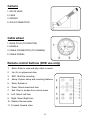
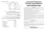
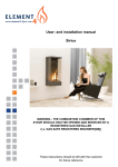
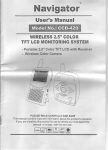
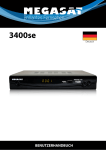
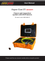
User Manual
Super Cam V7 SRCAMV7
Pipe & wall inspection
system with DVR feature.
Product code: SRCAM-V7
Please read this user manual carefully before using this product.
Specifications
Item
Description
Power adapter
AC100~240V
50/60Hz
DC12V1200mA
110VAC~240VAC
12VDC1800mA
Battery Case
Sealed, Lead
Li-on Acid
Maximum Camera Depth
65 Feet (Length of Cable)
Camera Light Source
Built-in White LED
Camera Angle-of-View
60° (horizontal), 60° (vertical)
Camera Depth-of-View
400 mm (approximate)
Camera Image
Colour
Color
Monitor Image
Colour
Color
Monitor Picture Resolution
320 (TV Lines)
Monitor Input Voltage
12 Volts DC
System Operating Temperature
-20°to 120°F
Save this Manual
Attention
1.
Read the user manual carefully before using this system.
2.
Avoid using
using the
thedevice
deviceininextremely
environments
extreme
cold, heat
or humidity
Avoid
cold, of
heat,
or humidity
environment,
it
as it damage
may damage
the device.
may
the device.
3.
Do not drop or press hard on the device.
4.
Warranty avoid if the device is opened by users or has physical damage.
5.
Always back up your data before connecting your USB device to this
system.The manufacturer is not responsible for any data damage on
to your
USB device for any reason.
6. Do not disconnect the unit while recording or playing. It may damage the
unit and/or the USB device
-1-
1
Application
WITH MINI-CAMERA FOR PIPE DIAMTER FROM 25MM TO 120MM ID
1.
WATER SUPPLY
2.
WASTE WATER
3.
ELECTRICAL AIRCONDITIONAL
4.
CABLE DUCTING
5.
DUCTED VACCUM SYSTEMS
6.
PLUMBING
7.
IN BUILDING S
Know Your Tool
9
14
1
2
3
4
5
6
7
10 11
12
16
13
8
15
9.
DC
DC 12V IN
1.
AV SELECTOR BOTTON
U
2.
MENU
3.
DOWN SELECTOR
11.
CAMERAPORT
PORT
CAMERA
4.
UP SELECTOR
12.
12.
USB PORT
5.
MENU UP/DOWN SELECTOR
13.
13.
POWER &
& CHARGE
CHARGE SWITCH
POWER
6.
LED ON/OFF BOTTON
U
14. AC
ACINPUT
INPUTPORT
PORT
14.
7.
POWER SWITCH
15. DC
DC12V
12VOUTPUT
OUTPUTCORD
CORD
15.
8.
FLAT TFT SCREEN
16.
10.
10. VIDEO
VIDEOOUT
OUT
-2-
SUNVISOR
VISOR
SUN
2
Camera
1. WHITE LEDS
2. LENS
3. SPRING
4. GOLD CONNECTER
Cable wheel
1. MALE PLUG (TO MONITOR)
2. HANDLE
3. CABLE CONNECTER (TO CAMERA)
4. CABLE WHEEL
Remote control buttons (DVD use only)
1.
Enter: Enter to view and play video or music
2.
Up: Go to up/previous item
3.
REC: Start the recording
4.
Setup: System setup and recording features
5.
Enter: System in
6.
Down: Select down/next item
7.
Exit: Stop or escape from current menu
8. Left: Select Left item
9. Right: Select Right item
10. Rewind: Review video
11. Forward: forward video
-3-
3
System Set-Up
System Set-Up
1.
1.
2.
2.
3.
3.
4.
4.
5.
5.
6.
6.
7.
7.
8.
8.
9.
9.
IMPORTANT: When connecting the Camera to the Monitor the power
IMPORTANT: When connecting the Camera to the Monitor the power
must be off or both units will be damaged.
must be off or both units will be damaged.
Screw the Camera to the Wheel Cable (See Figure1- A˅& Connect the Wheel
Screw the Camera to the Wheel Cable (See Figure1- A˅& Connect the Wheel
to the Monitor (See Figure 1-B).
to the Monitor (See Figure 1-B).
into
thethe
wallwall
AC AC
socket
and and
otherthe
endother
into the
Plug the
thePower
PowerAdapter
Adaptercord
cord
into
socket
endDC
Plug the Power Adapter cord into the wall AC socket and other end into the DC
into
the DC
12V-Input
to power
the Battery
unit from
mains
supply.
Or,
12V-Input
Jack,
or plug Jack
the cord
from the
Boxthe
into
the DC
12V-Input
12V-Input Jack, or plug the cord from the Battery Box into the DC 12V-Input
if powering the unit from the battery pack, screw the fuse provided into
Jack (See Figure1- C). If use the Battery Case Power, plug the Power Cord of
Jackside
(See
use the
Casethe
Power,
plugBox
the into
Power
the
ofFigure1the packC).
andIfplug
theBattery
cord from
Battery
theCord
DC of
Battery Case into the DC 12V-Input Jack.
12V-Input
Jack
Figure1
- C).Jack.
Battery Case
into(See
the DC
12V-Input
Turn on the POWER Switch on the front of the Monitor.
Turn on the POWER Switch on the front of the Monitor.
Gently lower the Camera into a pipe duct, etc and reel out the Cable until it is at
Gently lower the Camera into a pipe duct, etc and reel out the Cable until it is at
the desired depth.
the desired depth.
Turn on the LED Button & adjust the Brightness from the MENU.
Turn on the LED Button & adjust the Brightness from the MENU.
Record the pictures if you need (see DVR Operating).
Record the pictures if you need (see DVR Operating).
BY a video cable you can transfer the picture to other larger Screen.
BY a video cable you can transfer the picture to other
larger
Screen.
Via
another
larger
screen.
When finish, carefully remove the Camera from the pipe duct, etc. Screw out
When
finished,
carefully
remove
the Camera
the duct,
pipe etc.
duct,Screw
etc. Screw
When finish,
carefully
remove
the Camera
from from
the pipe
out out
the Camera and clean it with a clean, soft and dry cloth then put the Camera
the Camera and clean it with a clean, soft and dry cloth ,then
thenput
putthe
theCamera
Camera back
into the previous position.
to
intothe
theprevious
previousposition.
position.
C
C
B
B
Figure 1
Figure 1
-4-
AA
AA
4
4
DVR operation
1.
Set the Screen AV Button on
to Video 2.
2.
Take off the isolation sheet from the Remote Control Battery.
3.
Press the Remote Control Button 5
to Enter the Recording system,
you can
system
VIDEO
the screen.
then
yousee
will DVR
see the
DVRPLAY
system
PLAYmanual
VIDEOon
manual
on the screen.
4.
Insert your USB recorder (USB flash or removable hard disc etc) into
to the
the
USB Port, you
can see
CONNECTED
on the screen
the USB
whereby
youUSB
will see
USB CONNECTED
on the& screen
& LED
the
USB
LEDon.
light turn on.
light turn
5.
Press Remote Control Button 3
to start the recording & the
RECORDING LED light will
turnturn
on. on.
6.
Press Remote Control Button 7
7.
Press Remote Control Button 1
8.
If you need to manage your recording pictures, press Remote Control
Button 4
STOP
to stop the recording.
to review the recording.
. Alsoyou
you can
can do
undertake
filemanagement
management by
by electing
selectingthe
the
,also
this files
SETTING on PLAY VIDEO manual on the screen.
5
-5-
LED indicators
LED indicators
1˅ REM : Remote receiving window
Indicates
that the
is on
2˅
It indicates
system
issystem
on
1˅ Power:
REM : Remote
receiving
window
3˅ Power:
Recording:
It will blink
during
recording
2˅
It indicates
system
is on
4˅
It indicates
USB during
device recording
is connected
3˅ USB:
Recording:
It will blink
an error
5˅ USB:
Error: ItIt indicates
indicates USB
the system
device has error
4˅
device or
is USB
connected
6˅
It blinks
when the
remote
control
is in device
use Recording
5˅ IR:
Error:
It indicates
system
or USB
has error Video
The
recorded
video
files
will becontrol
found isinina use
directory
of USBVideo
devices.
6˅ IR:
It blinks
when
remote
Recording
Userrecorded
can use video
the on-screen
(REC)ofbutton
to start recording.
The
files will bemenu
foundorinpress
a directory
USB devices.
Press
(■/EXIT)
button
to stopmenu
recording.
During
the button
recording,
TV screen
will
User can
use the
on-screen
or press
(REC)
to start
recording.
display(■/EXIT)
recordingbutton
time and
timerecording.
limit (up toDuring
3 hours).
Press
to stop
the recording, TV screen will
User
can
press [setup]
button
to change
display
recording
time and
time limit
(up to 3recording
hours). time limit from 1 to 180
minutes.
recorded
be viewed
from a
computer.
chap
for9 for
computer.
(See
User
canThe
press
[setup]content
button can
to change
recording
time
limit See
from
1 chap
to 9180
more
details)
detail.
minutes.
The recorded content can be viewed from computer. See chap 9 for
Recording
time limit
more
detail.
Some users
users may
mayforget
forgettotostop
stopthe
recording
after
it has
been initiated.
recording
after
it is initiated.
So the Therefore
unit has
Recording time limit
the
unitusers
has time
a recording
whereby
the
time
ishas
2tohours.
a
recording
limit
feature,
The
default
time
limitit is
is
2 default
hours. So
User
can
Some
may
forget
totime
stoplimit
the feature
recording
after
initiated.
thelimit
unitgo
The
usermode
can
go
to SETUP
to increase
decrease
the
limit from
1 to
SETUP
to increase
or mode
decrease
the time
limit or
from1
minutes.
a
recording
time
limit
feature,
The default
limit
isto2 180
hours.
User
can go
to 180
minutes.
Schedule
SETUP mode recording
to increase or decrease the limit from1 to 180 minutes.
User
can schedule
a recording in advance. Simply enable the schedule
Schedule
recording
recording
the SETUP.
Then the
will ask
user enable
to setupthe
timing.
See
User can in
schedule
a recording
in unit
advance.
Simply
schedule
chapter 6 for
details. Then the unit will ask user to setup timing. (See
recording
in more
the SETUP.
Recording
schedule
can be
) used once. User has to set up schedule again for
chapter 6 for
more details.
next
recording.
6
The recording
schedule
be used
once,
the up
user
has to set
up for
the
Recording
schedule
can can
be used
once.only
User
has as
to set
schedule
again
schedule
again for the next recording.
next
recording.
-6-
6
Recording
USB
device
Recording
to USB
device
Recording
totoUSB
device
The
record
video
into
USB
devices
such
as
USB
hard
disk
.The
a
USB
hard
disk.
The
TheThe
unit
is unit
able
toable
record
video
into
USB
devices
suchsuch
as
USB
hard
disk
.The
unit
is is
able
to to
record
video
into
USB
devices
as
USB
hard
disk
.The
recorded
video
stored
USB
devices
and
played
back
device
and
be
played
back
on
the
TV
recorded
video
will be
stored
in the
USB
devices
andcan
played
backback
on
the
TV
recorded
video
willwill
bebe
stored
in in
thethe
USB
devices
and
played
onon
thethe
TVTV
screen.
screen.
screen.
Recording
format
Recording
format
Recording
format
The
default
recording
resolution
640*480,
which
takes
about
500MB/hour.
TheThe
default
recording
resolution
is 640*480,
which
takes
about
500MB/hour.
default
recording
resolution
is is
640*480,
which
takes
about
500MB/hour.
User
may
select
320*240
save
storage
space.
UserUser
may
select
320*240
to save
storage
space.
may
select
320*240
to to
save
storage
space.
Video
play
Video
play
Video
play
User
can
use
on-screen
menu
enter
“play
video”
mode.
The
unit
UserUser
can
use
on-screen
menu
to enter
“play
video”
mode.
The The
unit
will
display
the
on-screen
menu
toto
enter
“play
video”
mode.
The
unit
display
can
use
on-screen
menu
to
enter
“play
video”
mode.
unit
willwill
display
recorded
video
and
other
compatible
videos
inside
USB
device.
the USB
device.
the recorded
video
and
other
compatible
videos
inside
USB
device.
thethe
recorded
video
and
other
compatible
videos
inside
device.
It will
non-compatible
videos.
It willIt not
list
the
non-compatible
videos.
will
notnot
listlist
thethe
non-compatible
videos.
Select
thevideo
video
file.
Select
thethe
video
file.file.
Select
When
the
enters
“play
video”
mode,
set
will
display
available
When
user
enters
“play
video”
node,
will
display
all
of
the
available
useruser
enters
“play
video”
node,
the the
setthe
willset
display
all all
ofallof
the
available
When
user
enters
“play
video”
node,
the
set
will
display
ofthe
the
available
video
files
on
the
TVTV
screen.
video
files
screen.
files
on
TV
screen.
video
files
onon
TV
screen.
User
will
use
button
select
desired
video
and
press
[►/ENT]
button
UserUser
can
press
User
will
use
[▲]
or
[▼]
button
to select
desired
video
and
press
[►/ENT]
button
to to to
will
use
[▲][▲]
or or
[▼][▼]
button
to to
select
desired
video
and
press
[►/ENT]
button
play.
play.play.
Press
and
hold
[▼]
button
to
go
previous
next
video.
Press
and and
hold
[▲]
or[▲]
[▼]
button
to gototo
or next
video.
Press
hold
[▲]
or or
[▼]
button
goprevious
to to
previous
or or
next
video.
Use
[►/ENT]
button
pause
playing
.Use
[■/exit]
button
playback.
Use
the
UseUse
[►/ENT]
button
to start
orstart
pause
the playing
.Use
[■/exit]
button
to stop
orstop
[►/ENT]
button
to to
start
or or
pause
thethe
playing
.Use
[■/exit]
button
to to
stop
or or
previous
menu.
go back
toback
previous
menu.
the
previous
menu.
gogo
back
to to
menu.
The
screen
display
“loading,
please
wait
for
few
seconds
before
playing
The The
screen
will display
“loading,
please
wait wait
…”
for
few
seconds
before
playing
a
few
seconds
before
playing
screen
willwill
display
“loading,
please
…”…”
for
few
seconds
before
playing
video.
video.
video.
Fast
forward
and
rewind
Fast
forward
andand
rewind
Fast
forward
rewind
User
can
use
[◄]
button
the
remote
control
fast
forwarding
or or or or
UserUser
can
use
[►]
or[►]
[◄]
button
on the
remote
control
to fast-forward
fast
forwarding
can
use
[►]
or or
[◄]
button
onon
the
remote
control
to to
fast
forwarding
rewinding
(1x,2
x,4x,
8x,
speed).Always
press[►/ENT]
button
back
to
rewinding
x,4x,
or
8x,
speed).Always
press[►/ENT]
button
to go
back
rewinding
or or
8x,
speed).Always
press[►/ENT]
button
to to
gogo
back
rewind
(1x,(1x,2
2x,(1x,2
4x
orx,4x,
8x
speed).
Always
press
normal
playing.
normal
playing.
normal
playing.
Compatible
video
format:
Compatible
video
format:
Compatible
video
format:
Divx3.11/Divx4/Divx5/MPEG1/MPEG2/MPEG4
(MPEG4
video
format:
.avi,
Divx3.11/Divx4/Divx5/MPEG1/MPEG2/MPEG4
(MPEG4
video
file
format:
.avi,.avi,
Divx3.11/Divx4/Divx5/MPEG1/MPEG2/MPEG4
(MPEG4
video
filefile
format:
.m4v,
.MPG,
MPEG,
.VOB)
.m4v,
.MPG,
MPEG,
.VOB)
.m4v,
.MPG,
MPEG,
.VOB)
Note:
video
does
not
support
many
downloaded
video.
Video
does
not
support
anymany
downloaded
video
content.
Note:
video
does
not
support
many
downloaded
video.
Note:
video
does
not
support
downloaded
video.
7
-7-
77
System setup
recordings
andother
otherfeatures
featuresduring
duringthe
User can select different standards,
standard, recording
and
setup.
Also,
the user
can upgrade
thefirmware
unit firmware
or restore
to factory
default settings.
Also user
can upgrade
the unit
or restore
to factory
setting.
Recording setup
Recording time limit: 00:00-03:00(default is 2 hours)
Video standard: PAL or NTSC (default NTSC)
Resolution: 640*480,480*360,720*480 and 320*240(default 640*480)
Compression rate: 1000, 1200, 1500, 1800, 2100, 2500KB/S (default
1000kb/s)
Sample frequency: 24.32khz(default 32khz
Schedule recording: on/off (default off)
8
-8-
Recharge
1) Plug the AC cord into wall AC socket & insert the other end into
the Battery Box AC jack˄See Figure2- A˅
the charge
switchswitch˄See
(See Figure2-B)
2) Press down
the charge
Figure2-B˅
3) The
Charge
LEDLED
will will
be illuminate
Red during
& turn to& be
charge
redcharging
during charging
will Green
turn green
when
charging(normally
charging
time 8- 10
hours).
once finish
charging
has been completed
(charging
time
normally 8-10 hours).
A
B
Figure 2
Do not overcharge the battery; overcharging can result in damage to or acid
leaking from the battery.
9
-9-
Assembly drawing and parts list
Part No.
Description
1
CAMERA
2
MONITOR
3
60 FEET CABLE WITH WHEEL (LONG)
4
AC CORD
5
BATTERY CASE
6
BIG CASE
7
DC 12V POWER SUPPLY
8
SUNSHADE
9
BALL PROTECTION
10
SOFT CABLE (SHORT)
11
REMOTE CONTROL
12
DISC
Note:
youcannot
can read
not the
readrecording
the recording
pictures
on your
Note: If
If you
pictures on
your computer,
computer,
please down
load the
Codec from
software
fromprovided.
the disc.
please download
the Codec
software
the disc
10
-10-