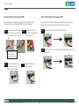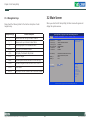
1
NEXCOM International Co., Ltd.
Industrial Computing Solutions
Industrial Motherboards
NEX 611
User Manual
NEXCOM International Co., Ltd.
Published September 2013
www.nexcom.com
Contents
Contents
Preface
Chapter 2: Installation
Copyright .............................................................................................. iv
Disclaimer .............................................................................................. iv
Acknowledgements ............................................................................... iv
Regulatory Compliance Statements ........................................................ iv
Declaration of Conformity....................................................................... iv
RoHS Compliance.................................................................................... v
Warranty and RMA................................................................................. vi
Safety Information .................................................................................vii
Installation Recommendations.................................................................vii
Safety Precautions..................................................................................viii
Technical Support and Assistance............................................................ ix
Conventions Used in this Manual............................................................ ix
Global Service Contact Information.......................................................... x
Package Contents..................................................................................xiii
2.1 Installing Memory Modules (DIMM)...................................................7
2.2 Expansion Slots (PCI Express Slots)......................................................8
2.3 Installing SATA Hard Disks..................................................................8
2.4 Power Connectors.............................................................................9
2.5 Installing the System Panel ..............................................................10
2.6 Onboard Headers and Connectors...................................................11
2.7 Expansion Slots (PCI, PCI Express and mini-PCIe Slots)......................18
2.8 Operating System Setup...................................................................20
2.9 Installing Drivers...............................................................................22
2.10 Hot Plug and Hot Swap for Hard Disk Drives..................................23
Chapter 3: UEFI Setup utility
3.1 Introduction ....................................................................................26
3.1.1 UEFI Menu Bar............................................................................26
3.1.2 North Bridge Configuration........................................................27
3.2 Main Screen ....................................................................................27
3.3 Advanced Screen ............................................................................28
3.3.1 CPU Configuration.....................................................................29
3.3.2 North Bridge Configuration........................................................30
3.3.3 South Bridge Configuration........................................................31
3.3.4 Storage Configuration................................................................32
3.3.5 Super IO Configuration...............................................................33
3.3.6 ACPI Configuration....................................................................34
Chapter 1: Introduction
1.1 Package Contents..............................................................................1
1.2 Specifications.....................................................................................1
1.3 Unique Features.................................................................................3
1.4 Motherboard Layout..........................................................................4
1.5 I/O Panel............................................................................................6
Copyright © 2011 NEXCOM International Co., Ltd. All Rights Reserved.
ii
NEX 611 User Manual
Contents
3.3.7 USB Configuration......................................................................35
3.3.8 Trusted Computing.....................................................................36
3.4 Hardware Health Event Monitoring Screen ......................................38
3.5 Boot Screen ....................................................................................39
3.6 Security Screen ...............................................................................40
3.7 Exit Screen.......................................................................................41
Copyright © 2011 NEXCOM International Co., Ltd. All Rights Reserved.
iii
NEX 611 User Manual
Preface
Preface
Copyright
Regulatory Compliance Statements
This publication, including all photographs, illustrations and software, is
protected under international copyright laws, with all rights reserved. No
part of this manual may be reproduced, copied, translated or transmitted
in any form or by any means without the prior written consent from
NEXCOM International Co., Ltd.
This section provides the FCC compliance statement for Class B devices
and describes how to keep the system CE compliant.
Declaration of Conformity
FCC
Disclaimer
This equipment has been tested and verified to comply with the limits for
a Class B digital device, pursuant to Part 15 of FCC Rules. These limits are
designed to provide reasonable protection against harmful interference
when the equipment is operated in a commercial environment. This equipment generates, uses, and can radiate radio frequency energy and, if not
installed and used in accordance with the instructions, may cause harmful
interference to radio communications. Operation of this equipment in a
residential area (domestic environment) is likely to cause harmful interference, in which case the user will be required to correct the interference
(take adequate measures) at their own expense.
The information in this document is subject to change without prior notice
and does not represent commitment from NEXCOM International Co., Ltd.
However, users may update their knowledge of any product in use by constantly checking its manual posted on our website: http://www.nexcom.
com. NEXCOM shall not be liable for direct, indirect, special, incidental, or
consequential damages arising out of the use of any product, nor for any
infringements upon the rights of third parties, which may result from such
use. Any implied warranties of merchantability or fitness for any particular
purpose is also disclaimed.
CE
Acknowledgements
The product(s) described in this manual complies with all applicable European Union (CE) directives if it has a CE marking. For computer systems to
remain CE compliant, only CE-compliant parts may be used. Maintaining
CE compliance also requires proper cable and cabling techniques.
NEX 611 is a trademark of NEXCOM International Co., Ltd. All other product names mentioned herein are registered trademarks of their respective
owners.
Copyright © 2011 NEXCOM International Co., Ltd. All Rights Reserved.
iv
NEX 611 User Manual
Preface
RoHS Compliance
How to recognize NEXCOM RoHS Products?
For existing products where there are non-RoHS and RoHS versions, the suffix “(LF)” will be added to the compliant product name.
NEXCOM RoHS Environmental Policy and Status
Update
All new product models launched after January 2006 will be RoHS compliant. They will use the usual NEXCOM naming convention.
NEXCOM is a global citizen for building the digital infrastructure. We are committed to providing green products
and services, which are compliant with European Union
RoHS (Restriction on Use of Hazardous Substance in Electronic Equipment)
directive 2002/95/EU, to be your trusted green partner and to protect our
environment.
RoHS restricts the use of Lead (Pb) < 0.1% or 1,000ppm, Mercury (Hg)
< 0.1% or 1,000ppm, Cadmium (Cd) < 0.01% or 100ppm, Hexavalent
Chromium (Cr6+) < 0.1% or 1,000ppm, Polybrominated biphenyls (PBB) <
0.1% or 1,000ppm, and Polybrominated diphenyl Ethers (PBDE) < 0.1% or
1,000ppm.
In order to meet the RoHS compliant directives, NEXCOM has established an
engineering and manufacturing task force in to implement the introduction
of green products. The task force will ensure that we follow the standard
NEXCOM development procedure and that all the new RoHS components
and new manufacturing processes maintain the highest industry quality
levels for which NEXCOM are renowned.
The model selection criteria will be based on market demand. Vendors and
suppliers will ensure that all designed components will be RoHS compliant.
Copyright © 2011 NEXCOM International Co., Ltd. All Rights Reserved.
v
NEX 611 User Manual
Preface
Warranty and RMA
NEXCOM Warranty Period
?? Any products returned by NEXCOM to other locations besides the customers’ site will bear an extra charge and will be billed to the customer.
NEXCOM manufactures products that are new or equivalent to new in
accordance with industry standard. NEXCOM warrants that products will
be free from defect in material and workmanship for 2 years, beginning
on the date of invoice by NEXCOM. HCP series products (Blade Server)
which are manufactured by NEXCOM are covered by a three year warranty
period.
Repair Service Charges for Out-of-Warranty Products
NEXCOM will charge for out-of-warranty products in two categories, one
is basic diagnostic fee and another is component (product) fee.
System Level
?? Component fee: NEXCOM will only charge for main components such
as SMD chip, BGA chip, etc. Passive components will be repaired for
free, ex: resistor, capacitor.
NEXCOM Return Merchandise Authorization (RMA)
?? Customers shall enclose the “NEXCOM RMA Service Form” with the
returned packages.
?? Items will be replaced with NEXCOM products if the original one cannot
be repaired. Ex: motherboard, power supply, etc.
?? Customers must collect all the information about the problems encountered and note anything abnormal or, print out any on-screen messages,
and describe the problems on the “NEXCOM RMA Service Form” for
the RMA number apply process.
?? Replace with 3rd party products if needed.
?? If RMA goods can not be repaired, NEXCOM will return it to the customer without any charge.
?? Customers can send back the faulty products with or without accessories (manuals, cable, etc.) and any components from the card, such as
CPU and RAM. If the components were suspected as part of the problems, please note clearly which components are included. Otherwise,
NEXCOM is not responsible for the devices/parts.
Board Level
?? Component fee: NEXCOM will only charge for main components, such
as SMD chip, BGA chip, etc. Passive components will be repaired for
free, ex: resistors, capacitors.
?? Customers are responsible for the safe packaging of defective products,
making sure it is durable enough to be resistant against further damage
and deterioration during transportation. In case of damages occurred
during transportation, the repair is treated as “Out of Warranty.”
Copyright © 2011 NEXCOM International Co., Ltd. All Rights Reserved.
?? If RMA goods can not be repaired, NEXCOM will return it to the customer without any charge.
vi
NEX 611 User Manual
Preface
Warnings
Installation Recommendations
Read and adhere to all warnings, cautions, and notices in this guide and
the documentation supplied with the chassis, power supply, and accessory
modules. If the instructions for the chassis and power supply are inconsistent with these instructions or the instructions for accessory modules,
contact the supplier to find out how you can ensure that your computer
meets safety and regulatory requirements.
Ensure you have a stable, clean working environment. Dust and dirt can
get into components and cause a malfunction. Use containers to keep
small components separated.
Adequate lighting and proper tools can prevent you from accidentally
damaging the internal components. Most of the procedures that follow
require only a few simple tools, including the following:
Cautions
Electrostatic discharge (ESD) can damage system components. Do the described procedures only at an ESD workstation. If no such station is available, you can provide some ESD protection by wearing an antistatic wrist
strap and attaching it to a metal part of the computer chassis.
•
•
•
•
Safety Information
Using your fingers can disconnect most of the connections. It is recommended that you do not use needlenose pliers to disconnect connections
as these can damage the soft metal or plastic parts of the connectors.
Before installing and using the device, note the following precautions:
▪▪ Read all instructions carefully.
▪▪ Do not place the unit on an unstable surface, cart, or stand.
▪▪ Follow all warnings and cautions in this manual.
▪▪ When replacing parts, ensure that your service technician uses parts
specified by the manufacturer.
▪▪ Avoid using the system near water, in direct sunlight, or near a heating
device.
▪▪ The load of the system unit does not solely rely for support from the
rackmounts located on the sides. Firm support from the bottom is highly
necessary in order to provide balance stability.
▪▪ The computer is provided with a battery-powered real-time clock circuit.
There is a danger of explosion if battery is incorrectly replaced. Replace
only with the same or equivalent type recommended by the manufacturer. Discard used batteries according to the manufacturer’s instructions.
Copyright © 2011 NEXCOM International Co., Ltd. All Rights Reserved.
A Philips screwdriver
A flat-tipped screwdriver
A grounding strap
An anti-static pad
vii
NEX 611 User Manual
Preface
Safety Precautions
12. If the equipment is not used for a long time, disconnect it from the
power source to avoid damage by transient overvoltage.
1.
Read these safety instructions carefully.
2.
Keep this User Manual for later reference.
13. Never pour any liquid into an opening. This may cause fire or electrical shock.
3.
Disconnect this equipment from any AC outlet before cleaning. Use a
damp cloth. Do not use liquid or spray detergents for cleaning.
14. Never open the equipment. For safety reasons, the equipment should
be opened only by qualified service personnel.
4.
For plug-in equipment, the power outlet socket must be located near
the equipment and must be easily accessible.
15. If one of the following situations arises, get the equipment checked
by service personnel:
5.
Keep this equipment away from humidity.
a. The power cord or plug is damaged.
6.
Put this equipment on a stable surface during installation. Dropping
it or letting it fall may cause damage.
b. Liquid has penetrated into the equipment.
7.
Do not leave this equipment in either an unconditioned environment
or in a above 40oC storage temperature as this may damage the
equipment.
d. The equipment does not work well, or you cannot get it to work
according to the user’s manual.
The openings on the enclosure are for air convection to protect the
equipment from overheating. DO NOT COVER THE OPENINGS.
f. The equipment has obvious signs of breakage.
8.
9.
c. The equipment has been exposed to moisture.
e. The equipment has been dropped and damaged.
16. Do not place heavy objects on the equipment.
Make sure the voltage of the power source is correct before connecting the equipment to the power outlet.
17. The unit uses a three-wire ground cable which is equipped with a
third pin to ground the unit and prevent electric shock. Do not defeat
the purpose of this pin. If your outlet does not support this kind of
plug, contact your electrician to replace your obsolete outlet.
10. Place the power cord in a way so that people will not step on it. Do
not place anything on top of the power cord. Use a power cord that
has been approved for use with the product and that it matches the
voltage and current marked on the product’s electrical range label.
The voltage and current rating of the cord must be greater than the
voltage and current rating marked on the product.
18. CAUTION: DANGER OF EXPLOSION IF BATTERY IS INCORRECTLY
REPLACED. REPLACE ONLY WITH THE SAME OR EQUIVALENT TYPE
RECOMMENDED BY THE MANUFACTURER. DISCARD USED BATTERIES ACCORDING TO THE MANUFACTURER’S INSTRUCTIONS.
11. All cautions and warnings on the equipment should be noted.
Copyright © 2011 NEXCOM International Co., Ltd. All Rights Reserved.
19. The computer is provided with CD drives that comply with the appropriate safety standards including IEC 60825.
viii
NEX 611 User Manual
Preface
Technical Support and Assistance
Conventions Used in this Manual
1. For the most updated information of NEXCOM products, visit NEXCOM’s website at www.nexcom.com.
Warning: Information about certain situations, which if not
observed, can cause personal injury. This will prevent injury to
yourself when performing a task.
2. For technical issues that require contacting our technical support team
or sales representative, please have the following information ready
before calling:
Caution: Information to avoid damaging components or losing
data.
– Product name and serial number
– Detailed information of the peripheral devices
– Detailed information of the installed software (operating system,
version, application software, etc.)
– A complete description of the problem
– The exact wordings of the error messages
Note: Provides additional information to complete a task easily.
Warning!
1. Handling the unit: carry the unit with both hands and handle it with
care.
2. Maintenance: to keep the unit clean, use only approved cleaning products or clean with a dry cloth.
3. CompactFlash: Turn off the unit’s power before inserting or removing a
CompactFlash storage card.
Copyright © 2011 NEXCOM International Co., Ltd. All Rights Reserved.
ix
NEX 611 User Manual
Preface
Global Service Contact Information
Headquarters
NEXCOM International Co., Ltd.
15F, No. 920, Chung-Cheng Rd., ZhongHe
District, New Taipei City, 23586, Taiwan,
R.O.C.
Tel: +886-2-8226-7786
Fax: +886-2-8226-7782
www.nexcom.com.tw
America
USA
NEXCOM USA
2883 Bayview Drive,
Fremont CA 94538, USA
Tel: +1-510-656-2248
Fax: +1-510-656-2158
Email: [email protected]
www.nexcom.com
Asia
Taiwan
Taichung Office
16F, No.250, Sec. 2,
Chongde Rd., Beitun Dist.,
Taichung City 406, R.O.C.
Tel: +886-4-2249-1179
Fax: +886-4-2249-1172
www.nexcom.com.tw Japan
Copyright © 2011 NEXCOM International Co., Ltd. All Rights Reserved.
NEXCOM Japan
9F, Tamachi Hara Bldg.,4-11-5, Shiba
Minato-ku,
Tokyo, 108-0014, Japan
Tel: +81-3-5419-7830
Fax: +81-3-5419-7832
Email: [email protected]
www.nexcom-jp.com
China
NEXCOM China
Nanjing Office
Hall C, Block 17, Tian Xing Cui Lang Bldg.,
No. 49 Yunnan North Rd.,
Nanjing, 210018, China
Tel: +86-25-8315-3486
Fax: +86-25-8315-3489
Email: [email protected]
www.nexcom.cn
Shenzhen Office
2F, Block 4, Venus Plaza, Building 21,
ZhongGuanCun Software Park, No.8,
Dongbeiwang West Road, Haidian District,
Beijing, 100193, China
Tel: +86-10-8282-5880
Fax: +86-10-8282-5955
Email: [email protected]
www.nexcom.cn
Western Room 708, Block 210,
Tairan Industry & Trading Place, Futian
Area,
Shenzhen, 518040, China
Tel: +86-755-833 7203
Fax: +86-755-833 7213
Email: [email protected]
www.nexcom.cn
Wuhan Office
Shanghai Office
Room 1505, Greenland He Chuang Bldg.,
No. 450 Caoyang Rd.,
Shanghai, 200062, China
Tel: +86-21-6150-8008
Fax: +86-21-3251-6358
Email: [email protected]
www.nexcom.cn
x
1-C1804/1805,Mingze Liwan, No.519
South Luoshi Rd,Hongshan District,
Wuhan,430070,China
Tel: +86-27-8722-7400
Fax: +86-27-8722-7400
Email: [email protected]
www.nexcom.cn
NEX 611 User Manual
Preface
Chengdu Office
Italy
Chengdu Office 9F,Shuxiangxie,Xuefu
Garden, No.12 Section 1,South Yihuan
Rd,Chengdu, 610061,China
Tel: +86-28-8523-0186
Fax: +86-28-8523-0186
Email: [email protected]
www.nexcom.cn
NEXCOM ITALIA S.r.l
Via Gaudenzio Ferrari 29,
21047 Saronno (VA), Italia
Tel: +39 02 9628 0333
Fax: +39 02 9286 9215
Email: [email protected]
www.nexcomitalia.it
Europe
United Kingdom
NEXCOM EUROPE
France
NEXCOM France
La Grande Arche-Paroi Nord
92044 Paris La Défense
France
Tel: +33 (0) 1 40 90 33 35
Fax: +33 (0) 1 40 90 31 01
Email: [email protected]
www.nexcom.eu
10 Vincent Avenue,
Crownhill Business Centre,
Milton Keynes, Buckinghamshire
MK8 0AB, United Kingdom
Tel: +44-1908-267121
Fax: +44-1908-262042
Email: [email protected]
www.nexcom.eu
Germany
NEXCOM GmbH
Leopoldstraße Business Centre,
Leopoldstraße 244,
80807 Munich, Germany
Tel: +49-89-208039-278
Fax: +49-89-208039-279
Email: [email protected]
www.nexcom.eu
Copyright © 2011 NEXCOM International Co., Ltd. All Rights Reserved.
xi
NEX 611 User Manual
Chapter 1: Introduction
Chapter 1: Introduction
Thank you for purchasing NEXCOM NEX 611 motherboard, a reliable
motherboard produced under NEXCOM consistently stringent quality
control. It delivers excellent performance with robust design conforming to
NEXCOM commitment to quality and endurance.
1.1 Package Contents
In this manual, chapter 1 and 2 contains the introduction of the
motherboard and step-by-step hardware installation guide. Chapter 3 and
4 contains the configuration guide of BIOS setup and information of the
Support CD.
NEXCOM NEX 611 Quick Installation Guide
NEXCOM NEX 611 Motherboard
(Mini-ITX Form Factor: 6.7-in x 6.7-in, 17.0 cm x 17.0 cm)
NEXCOM NEX 611 Support CD
2 x Serial ATA (SATA) Data Cables
1 x Serial ATA (SATA) HDD Power Cables
1 x I/O Panel Shield
Because the motherboard specifications and the BIOS software
might be updated, the content of this manual will be subject to
change without notice. In case any modifications of this manual
occur, the updated version will be available on NEXCOM website
without further notice. You may find the latest VGA cards and
CPU support list on NEXCOM website as well. NEXCOM website
http://www.nexcom.com
If you require technical support related to this motherboard,
please visit our website for specific information about the model
you are using.
http://www.nexcom.com/Inquiry/InquiryModel
Copyright © 2011 NEXCOM International Co., Ltd. All Rights Reserved.
1.2 Specifications
Platform
CPU
Mini-ITX Form Factor: 6.7-inx 6.7-in, 17.0 cmx 17.0 cm
All Solid Capacitor design (100% Japan-made high
quality Conductive Polymer Capacitors)
Supports AMD Embedded G-Series APU T56N/ T48E/
T40E
Supports AMD Virtualization Technology
1
Chipset
Memory
AMD A50M/ A55E Controller Hub
Memory
Single Channel DDR3 memory technology
2x 204-pin DDR3 SO-DIMM slots
T56N supports DDR3 1333/ 1066 MHz SDRAM, T48E/
T40E supports DDR3 1066 MHz SDRAM
Max. capacity of system memory: 8GB (see CAUTION 1)
NEX 611 User Manual
Chapter 1: Introduction
Expansion
Slots
Graphics
Audio
LAN
1 x PS/ 2 Mouse/ Keyboard Port
1 x D-Sub Port
Rear Panel I/O 2 x HDMI Ports (Optional)
2 x Serial Ports (RS-232/ 422/ 485)
6 x Ready-to-Use USB 2.0 Ports
2 x RJ-45 LAN Ports with LED
(ACT/ LINK LED and SPEED LED)
HD Audio Jacks: Line Out/ MIC In
4 x SATA3 6.0 Gb/s connectors, support RAID
SATA3
(RAID 0, RAID 1, RAID 5 and RAID 10), NCQ, AHCI and
Hot Plug (Raid is not supported by AMD A50M)
4 x SATA3 6.0 Gb/s connectors
4 x COM port headers
1 x LVDS header (Optional)
1 x Printer port
1 x Mini SATA slot
1 x TPM header
Connectors
1 x CPU Fan connector (1 x 4-pin)
1 x Chassis Fan connector (1 x 3-pin)
4 pin 12V power connector
SATA power connector
Front panel audio connector
3 x USB 2.0 headers (support 6 USB 2.0 ports)
1 x Vertical Type A USB
1x PCI Express 2.0 x4 slot (PCIE1: x4 mode)
1x Mini-PCI Express slot (Half size)
AMD Radeon HD 6320 with T56N, AMD Radeon HD
6250 with T48E/ T40E
Supports Pixel Shader 5.0, DirectX 11
Max. shared memory 256MB
Three VGA Output options: D-Sub, LVDS and HDMI
Supports D-Sub with max. resolution up to
2560 x 1600 @ 60Hz for T56N or 1920 x 1200 for
T48E/ T40E
Supports 2-CH/24bits LVDS with max. resolution up to
1920x1200 @ 60Hz (Optional)
Supports HDMI 1.3a Technology with max. resolution
up to 1920x1200 @ 60Hz (Optional)
2 CH Audio (Realtek ALC662 Audio Codec)
2 x Gigabit LAN 10/100/1000 Mb/s
Realtek RTL8111E
Supports Wake On LAN
Supports LAN Cable Detection
Supports Energy Efficient Ethernet 802.3az
Supports Dual LAN
Supports PXE
Copyright © 2011 NEXCOM International Co., Ltd. All Rights Reserved.
2
NEX 611 User Manual
Chapter 1: Introduction
BIOS Feature
Support CD
Hardware
Monitor
OS
Certifications
CAUTION!
32Mb AMI UEFI Legal BIOS with GUI support
Supports “Plug and Play”
ACPI 1.1 Compliance Wake Up Events
Supports jumperfree
SMBIOS 2.3.1 Support
Drivers
CPU/ Chassis Temperature Sensing Monitor
CPU/ Chassis/ Power Fan Tachometer
CPU/ Chassis Quiet Fan
Voltage Monitoring: +12V, +5V, +3.3V, CPU Vcore
Microsoft® Windows® 8/ 8 64-bit/ 7/ 7 64-bit/ VistaTM/
VistaTM 64-bit/ XP/ XP 64-bit compliant
FCC, CE, WHQL
1.Due to the operating system’s limitation, the actual memory size of the
reservation for system usage under Windows® 32-bit operating systems may
be less than 4GB. Windows® 64-bit operating systems have no such limitation.
1.3 Unique Features
NEXCOM Instant Flash
NEXCOM Instant Flash is a BIOS flash utility embedded in Flash ROM. This
convenient BIOS update tool allows you to update system BIOS without entering operating systems first like MS-DOS or Windows®. With this utility,
you can press the <F6> key during the POST or the <F2> key to enter into
the BIOS setup menu to access NEXCOM Instant Flash. Just launch this tool
and save the new BIOS file to your USB flash drive, floppy disk or hard drive,
then you can update your BIOS only in a few clicks without preparing an
additional floppy diskette or other complicated flash utility. Please be noted
that the USB flash drive or hard drive must use FAT32/16/12 file system.
For detailed product information, please visit our website:
http://www.nexcom.com
WARNING
NEXCOM Crashless BIOS
Please realize that there is a certain risk involved with overclocking, including adjusting the setting in the BIOS, applying Untied Overclocking
Technology, or using third-party overclocking tools. Overclocking may affect your system’s stability, or even cause damage to the components
and devices of your system. It should be done at your own risk and expense. We are not responsible for possible damage caused by overclocking
Copyright © 2011 NEXCOM International Co., Ltd. All Rights Reserved.
NEXCOM Crashless BIOS allows users to update their BIOS without fear
of failing. If power loss occurs during the BIOS update process, NEXCOM
Crashless BIOS will automatically finish the BIOS update procedure after regaining power. Please note that BIOS files need to be placed in the
root directory of your USB disk. Only USB2.0 ports support this feature.
3
NEX 611 User Manual
Chapter 1: Introduction
1.4 Motherboard Layout
1
3
2
4 5
1
1
1
BL T_PWR2
PS2
US B 2. 0
K eyboard T: USB 1
/Mous e B: USB 0
1
BKT_PWR 1
LV DS 1
7 8 9 10 11
6
BL T_VOL1
CPU_F AN1
1
PNL_PWR1
M_SA TA 1
AT X 12V 1
MINI_PCIE1
41
40
LPT1
DDR3_A1
HDMI2
COM2
SET_CM2
CHA_F AN1
1
1
JPWR 1
13
14
T PM1
32M b
B IOS
36
SA TA 3_2
LA N
RJ-45
SA TA 3_4
US B 2. 0
T: USB 3
B: USB 2
15
USB_6_7
US B 2. 0
T: USB 5
B: USB 4
1
S upe r
I/O
1
USB_8_9
RJ-45
SPEAKER_OUT1
16
SA TA 3_1
LA N
SA TA3_ 3
38
37
SET_CM1
1
CMOS
Battery
39
HDMI1
12
DDR3_A2
VGA1 COM1
17
1
1
USB_10_1 1
1
USB12
1
COM4
COM5
1
R ESET
SET_CM4
BUZZ1
PWRBT N
SET_CM3
AUDI O
CODE C
PLED
P ANE L 1
HDLED
HD_AUDIO1
Top:
Line In
Bottom:
Mic In
Center:
Line Out
1
COM3
CLRCOMOS1
1
1
1
D IO 1
COM6
PCIE 1
1
PWR_JP 1
18
19
20
21
Designe d in Ta ipei
35
Copyright © 2011 NEXCOM International Co., Ltd. All Rights Reserved.
34 33 32 29 30 31 28 27 26 25 24
4
23 22
NEX 611 User Manual
Chapter 1: Introduction
32 PCI Express Slot (PCIE1)
33 Vertical Type A USB (USB12)
34 Audio AMP Output Speaker Header (SPEAKER_OUT1)
35 Front Panel Audio Header (HD_AUDIO1)
36 TPM header (TPM1)
37 SPI Flash Memory (32Mb)
38 Chassis Fan Connector (CHA_FAN1)
39 COM Power Setting Jumper (SET_CM2)
40 COM Power Setting Jumper (SET_CM1)
41 Mini PCI Express Slot (MINI_PCIE1)
1 Mini SATA Slot (M_SATA1)
2 LVDS Connector (LVDS1)
3 Backlight Power Jumper (BKT_PWR1)
4 Inverter Power Control Header (BLT_PWR2)
5 Panel Power Jumper (PNL_PWR1)
6 Backlight & Amp Volume Control Header (BLT_VOL1)
7 CPU Fan Connector (CPU_FAN1)
8 CPU
9 AMD A50M/A55E Chipset
10 4-pin ATX 12V Power Connector
11 2 x 204-pin DDR3 SO-DIMM Slots (DDR3_A1, DDR3_A2, Black)
12 Printer Port (LPT1)
13 SATA Power Connector (JPWR1)
14 SATA3 Connector (SATA3_4, White)
15 SATA3 Connector (SATA3_2, White)
16 SATA3 Connector (SATA3_3, White)
17 SATA3 Connector (SATA3_1, White)
18 COM Port Header (COM3)
19 COM Port Header (COM4)
20 System Panel Header (PANEL1)
21 PWR-On Mode Jumper (PWR_JP1)
22 COM Port Header (COM6)
23 COM Port Header (COM5)
24 COM Power Setting Jumper (SET_CM3)
25 Digital I/O Header (DIO1)
26 COM Power Setting Jumper (SET_CM4)
27 Clear CMOS Jumper (CLRCMOS1)
28 Buzzer (BUZZ1)
29 USB 2.0 Header (USB6_7)
30 USB 2.0 Header (USB8_9)
31 USB 2.0 Header (USB10_11)
Copyright © 2011 NEXCOM International Co., Ltd. All Rights Reserved.
* FOptional
5
NEX 611 User Manual
Chapter 1: Introduction
1.5 I/O Panel
1
▪▪ There are two LED next to the LAN port.
Please refer to the table below for the LAN port LED indications.
2
4
3
5
LAN Port LED Indications
6
ACT/ LINK LED
SPEED LED
7
13
•
•
•
•
•
•
•
12
1 USB 2.0 Ports (USB01)
2 Serial Port (COM1)
3 Serial Port (COM2)
4 LAN RJ-45 Port (LAN2)
5 LAN RJ-45 Port (LAN1)
6 Front Speaker (Lime)
7 Microphone (Pink)
11
10
•
•
•
•
•
•
9
8
8 USB 2.0 Ports (USB45)
9 USB 2.0 Ports (USB23)
10 HDMI Port (HDMI1)
11 HDMI Port (HDMI2)
12 D-Sub (VGA1)
13 PS/ 2 Keyboard/ Mouse Port
LAN Port
Activity/ Link LED
Status
Off
Blinking
On
Description
No Link
Data Activity
100Mbps connection
Activity/ Link LED
Status
Off
Orange
Green
Description
10Mbps connection
100Mbps connection
1Gbps connection
* Optional
Copyright © 2011 NEXCOM International Co., Ltd. All Rights Reserved.
6
NEX 611 User Manual
Chapter 2: Installation
Chapter 2: Installation
This is a Mini-ITX form factor motherboard. Before you install the motherboard, study the configuration of your chassis to ensure that the motherboard fits into it.
2.1 Installing Memory Modules (DIMM)
Pre-installation Precautions
Step 1.
Step 2.
This motherboard provides two 204-pin DDR3 (Double Data Rate 3)
SO-DIMM slots.
Take note of the following precautions before you install motherboard
components or change any motherboard settings.
Unlock a DIMM slot by pressing the retaining clips outward.
Align a DIMM on the slot such that the notch on the DIMM
matches the break on the slot.
1. Make sure to unplug the power cord before installing or removing the
motherboard. Failure to do so may cause physical injuries to you and
damages to motherboard components.
2. In order to avoid damage from static electricity to the motherboard’s
components, NEVER place your motherboard directly on a carpet. Also
remember to use a grounded wrist strap or touch a safety grounded
object before you handle the components.
notch
break
notch
break
3. Hold components by the edges and do not touch the ICs.
4. Whenever you uninstall any components, place them on a grounded
The DIMM only fits in one correct orientation. It will cause permanent damage to the motherboard and the DIMM if you force
the DIMM into the slot at incorrect orientation.
anti-static pad or in the bag that comes with the components.
5. When placing screws to secure the motherboard to the chassis, please
do not over-tighten the screws! Doing so may damage the motherboard.
Copyright © 2011 NEXCOM International Co., Ltd. All Rights Reserved.
Step 3.
7
Firmly insert the DIMM into the slot until the retaining clips at
both ends fully snap back in place and the DIMM is properly
seated.
NEX 611 User Manual
Chapter 2: Installation
2.2 Expansion Slots (PCI Express Slots)
2.3 Installing SATA Hard Disks
There is 1 PCI Express slot and 1 mini PCI Express slot on this motherboard.
Step 1.
Connect the SATA power cable to the hard disk.
mini-PCIE Slots: mini_PCIE1 is used for mini PCIE cards.
Step 2.
Connect one end of the SATA data cable to the hard disk.
Step 3.
Align the card connector with the slot and press firmly until the
card is completely seated on the slot.
PCIE slots: The x4 lane width PCIE1 (PCIE 2.0 x4 slot) is used for PCI Express expansion cards.
Installing an expansion card
Step 1.
Before installing an expansion card, please make sure that the
power supply is switched off or the power cord is unplugged.
Please read the documentation of the expansion card and make
necessary hardware settings for the card before you start the
installation.
Step 2.
Remove the bracket facing the slot that you intend to use.
Keep the screws for later use.
Align the card connector with the slot and press firmly until the
card is completely seated on the slot.
Fasten the card to the chassis with screws.
Step 3.
Step 4.
Serial ATA3 Connectors
(SATA3_1: see p.10, No. 17)
SATA3_3 SATA3_4
(SATA3_2: see p.10, No. 15)
(SATA3_3: see p.10, No. 16)
(SATA3_4: see p.10, No. 14)
SATA3_1 SATA3_2
These four Serial ATA3 (SATA3) connectors support SATA data cables for
internal storage devices. The current SATA3 interface allows up to 6.0 Gb/s
data transfer rate.
Copyright © 2011 NEXCOM International Co., Ltd. All Rights Reserved.
8
NEX 611 User Manual
Chapter 2: Installation
2.4 Power Connectors
ATX 12V Power Connector
SATA Power Connector
(4-pin ATX12V1)
(4-pin JPWR1)
(see p.10, No.10)
(see p.10, No.13)
Please connect a power supply to this connector.
It is not necessary to use this connector, but please connect it with a
hard disk power connector when two graphics cards are plugged to this
motherboard.
+12V
GND
GND
1
Pin
Copyright © 2011 NEXCOM International Co., Ltd. All Rights Reserved.
9
Signal Name
+5V
Pin
Signal Name
1
+5V
2
GND
3
GND
4
+12V
NEX 611 User Manual
Chapter 2: Installation
2.5 Installing the System Panel
The front panel design may differ by chassis. A front panel module mainly
consists of power switch, reset switch, power LED, hard drive activity LED,
speaker and etc. When connecting your chassis front panel module to
this header, make sure the wire assignments and the pin assignments are
matched correctly.
Connect the power switch, reset switch and system status indicator on the
chassis to this header according to the pin assignments below. Note the
positive and negative pins before connecting the cables.
PWRBTN (Power Switch):
Connect to the power switch on the chassis front panel. You may
configure the way to turn off your system using the power switch.
The white wires are negative (Connect to - or GND pins), while
the colored ones are positive.
RESET (Reset Switch):
Connect to the reset switch on the chassis front panel. Press the reset
switch to restart the computer if the computer freezes and fails to perform
a normal restart.
System Panel Header
(9-pin PANEL1)
(see p.10, No.20)
PLED (System Power LED):
Connect to the power status indicator on the chassis front panel. The LED
is on when the system is operating. The LED keeps blinking when the system is in S1/S3 sleep state. The LED is off when the system is in S4 sleep
state or powered off (S5).
GND
GND
RESET#
GND
PWRBTN#
HDLED-
PLEDPLED+
HDLED+
1
HDLED (Hard Drive Activity LED):
Connect to the hard drive activity LED on the chassis front panel. The LED
is on when the hard drive is reading or writing data.
Copyright © 2011 NEXCOM International Co., Ltd. All Rights Reserved.
10
Pin
Signal Name
Pin
Signal Name
1
HDLED+
2
HDLED-
3
GND
4
RESET#1
5
GND
6
PLED+
7
PLED-
8
PWRBTN#
9
GND
NEX 611 User Manual
Chapter 2: Installation
2.6 Onboard Headers and Connectors
Print Port Header
Onboard headers and connectors are NOT jumpers. Do NOT
place jumper caps over these headers and connectors. Placing
jumper caps over the headers and connectors will cause
permanent damage to the motherboard!
(25-pin LPT1)
(see p.10, No.12)
SLCT
USB 2.0 Headers
USB_PWR
-B
+B
USB 2.0 Headers
GND
DUMMY
(9-pin USB6_7) (see p.10, No. 29)
1
(9-pin USB8_9) (see p.10, No. 30)
PE
GND
BUSY
GND
ACK#
GND
SPD7
GND
SPD6
GND
SPD5
+A
GND
SPD4
-A
USB_PWR
GND
SPD3
SLIN#
SPD2
PINIT#
SPD1
GND
(9-pin USB10_11) (see p.10, No. 31)
GND
(USB12) (see p.10, No. 33)
ERROR#
SPD0
AFD#
STB#
1
Besides six default USB 2.0 ports on the I/O panel, there are three USB 2.0
headers and one USB port on this motherboard. Each USB 2.0 header can
support two USB 2.0 ports.
Pin
Signal Name
Pin
Signal Name
1
USB_PWR
2
-A
3
+A
4
GND
6
USB_PWR
7
-B
8
+B
9
GND
10
DUMMY
Copyright © 2011 NEXCOM International Co., Ltd. All Rights Reserved.
Pin
11
Signal Name
Pin
Signal Name
Pin
Signal Name
1
STB#
2
SPD0
3
SPD1
4
SPD2
5
SPD3
6
SPD4
7
SPD5
8
SPD6
9
SPD7
10
ACK#
11
BUSY
12
PE
13
SLCT
14
AFD#
15
ERROR#
16
PINIT#
17
SLIN#
18
GND
21
GND
22
GND
24
GND
25
GND
NEX 611 User Manual
Chapter 2: Installation
Front Panel Audio Header
1. High Definition Audio supports Jack Sensing, but the panel
wire on the chassis must support HDA to function correctly.
Please follow the instructions in our manual and chassis
manual to install your system.
(9-pin HD_AUDIO1)
(see p.10, No.35)
2. If you use an AC’97 audio panel, please install it to the front
panel audio header by the steps below:
GND
PRESENCE#
MIC_RET
OUT_RET
A. Connect Mic_IN (MIC) to MIC2_L.
B. Connect Audio_R (RIN) to OUT2_R and Audio_L (LIN) to
1
OUT2_L.
OUT2_L
J_SENSE
OUT2_R
MIC2_R
MIC2_L
C. Connect Ground (GND) to Ground (GND).
D. MIC_RET and OUT_RET are for HD audio panel only. You
don’t need to connect them for AC’97 audio panel.
E. To activate the front mic.
For Windows® XP / XP 64-bit OS:
Pin
Signal Name
Pin
Signal Name
1
MIC2_L
2
MIC2_R
Select “Mixer”. Select “Recorder”. Then click “FrontMic”.
3
OUT2_R
4
J_SENSE
5
OUT2_L
6
GND
For Windows® 8/ 8 64-bit/ 7/ 7 64-bit/ VistaTM/ VistaTM
7
PRESENCE#
8
MIC_RET
10
OUT_RET
64-bit OS:
Go to the “FrontMic” Tab in the Realtek Control panel.
Adjust“Recording Volume”.
Copyright © 2011 NEXCOM International Co., Ltd. All Rights Reserved.
12
NEX 611 User Manual
Chapter 2: Installation
Audio AMP Output Speaker Header
Chassis Fan Connector
(4-pin SPEAKER_OUT1)
(3-pin CHA_FAN1)
(see p.10, No.34)
(see p.10, No.38)
Please connect a fan cable to the fan connector and match the black wire
to the ground pin.
OUTLP
1
1
OUTLN
OUTRN
GND
+12V
FAN_SPEED
OUTRP
1
Pin
Signal Name
Pin
1
SPK L+
2
3
SPK R-
4
Copyright © 2011 NEXCOM International Co., Ltd. All Rights Reserved.
Signal Name
Pin
Signal Name
Pin
Signal Name
SPK L-
1
FAN SPEED
2
+12V
SPK R+
3
GND
13
NEX 611 User Manual
Chapter 2: Installation
CPU Fan Connector
Serial Port Header
(4-pin CPU_FAN1)
(9-pin COM3)(see p.10, No.18)
(see p.10, No.7)
(9-pin COM4)(see p.10, No.19)
(9-pin COM5)(see p.10, No.23)
Though this motherboard provides a 4-Pin CPU fan (Quiet Fan) connector,
3-Pin CPU fans can still work successfully even without fan speed control.
If you plan to connect a 3-Pin CPU fan, please connect it to Pin 1-3.
(9-pin COM6)(see p.10, No.22)
These COM headers support serial port modules.
RRXD1
DDTR#1
DDSR#1
CCTS#1
FAN_SPEED_CONTROL
FAN_SPEED
+12V
GND
1
2
3
1
RRI#1
RRTS#1
GND
TTXD1
DDCD#1
4
Pin
Signal Name
Pin
Signal Name
Pin
Signal Name
Pin
Signal Name
1
GND
2
+12V
1
DDCD#1
2
TTXD1
3
FAN_SPEED
4
FAN_SPEED_CONTROL
Copyright © 2011 NEXCOM International Co., Ltd. All Rights Reserved.
14
3
GND
4
RRTS#1
5
RRI#1
6
RRXD1
7
DDTR#1
8
DDSR#1
9
CCIS#1
NEX 611 User Manual
Chapter 2: Installation
TPM Header
LVDS Connector (Optional)
(17-pin TPM1)
(40-pin LVDS1)
(see p.10, No.36)
(see p.10, No.2)
This connector supports Trusted Platform Module (TPM) system, which can
securely store keys, digital certificates, passwords, and data. A TPM system
also helps enhance network security, protects digital identities, and ensures
platform integrity.
F_CLKRUN#
1
39
2
40
GND
+3VSB
SERIRQ#
S_PWRDWN#
LAD0_L
GND
LAD1_L
+3V
LAD2_L
LAD3_L
SMB_DATA_MAIN
TPM_RST#
SMB_CLK_MAIN
LFRAME#_L
GND
Pin
CK_33M_TPM
1
Pin
Signal Name
Pin
Signal Name
Pin
Signal Name
1
CK_33M_TPM
2
LFRAME#_L
3
TPM_RST#
4
LAD3_L
5
+3V
6
LAD0_L
8
+3VSB
9
GND
10
GND
11
SMB_CLK_MAIN
12
SMB_DATA_MAIN
13
LAD2_L
14
LAD1_L
15
GND
16
S_PWRDWN#
17
SERIRQ#
17
F_CLKRUN#
Copyright © 2011 NEXCOM International Co., Ltd. All Rights Reserved.
15
Definition
Pin
Definition
Pin
Definition
1
LVDS_PWR
2
LVDS_PWR
3
+3V
4
DDC_CLK
5
DDC_DATA
6
LVDS1 D0(-)
7
LVDS1 D0(+)
8
GND
9
LVDS1 D1(-)
10
LVDS1 D1(+)
11
GND
12
LVDS1 D2(-)
13
LVDS1 D2(+)
14
GND
15
LVDS1 D3(-)
16
LVDS1 D3(+)
17
GND
18
LVDS1CLK(-)
19
LVDS1CLK(+)
20
GND
21
LVDS2 D0(-)
22
LVDS2 D0(+)
23
GND
24
LVDS2 D1(-)
25
LVDS2 D1(+)
26
GND
27
LVDS2 D2(-)
28
LVDS2 D2(+)
29
LVDS PWR EN
30
LVDS2 D3(-)
31
LVDS2 D3(+)
32
GND
33
LVDS2 CLK(-)
34
LVDS2 CLK(+)
35
GND
36
B/L ENABLE
37
B/L ADJUST
38
BLT_PWR
39
BLT_PWR
40
BLT_PWR
NEX 611 User Manual
Chapter 2: Installation
Inverter Power Control Header (Optional)
Backlight & Amp Volume Control Header (Optional)
(6-pin BLT_PWR2)
(7-pin BLT_VOL1)
(see p.10, No.4)
(see p.10, No.6)
1
Pin
Signal Name
Pin
1
Signal Name
Pin
Signal Name
Pin
Signal Name
1
GND
2
GND
1
Volume_UP
2
Volume_DOWN
3
Panel Backlight Control
4
Panel Backlight Enable
3
PANEL PWR Down
4
Panel BackLight UP
5
Panel Backlight Power
6
Panel Backlight Power
5
Panel BackLight Down
6
GND
7
GND
Copyright © 2011 NEXCOM International Co., Ltd. All Rights Reserved.
16
NEX 611 User Manual
Chapter 2: Installation
Digital I/O Header
Mini SATA Connector
(10-pin DIO1)
This mini SATA connector can be used to connect a Solid-State Drive (SSD)
for an internal storage device. Or used for USB interface addon cards.
(see p.10, No.25)
1
Pin
Signal Name
Pin
Signal Name
1
GP4
2
GP0
3
GP5
4
GP1
5
GP6
6
GP2
7
GP7
8
GP3
9
+5V
10
GND
Copyright © 2011 NEXCOM International Co., Ltd. All Rights Reserved.
17
NEX 611 User Manual
Chapter 2: Installation
2.7 Expansion Slots
(PCI, PCI Express and mini-PCIe Slots)
There are 2 PCI slots, 2 PCI Express slots and 1 mini-PCIe slot on this motherboard.
Clear CMOS Jumper
Jumper
(3-pinCLRCMOS1)
(see p.10, No.27)
Default Clear CMOS
CLRCMOS1 allows you to clear the data in CMOS. To clear and reset the system parameters to default setup, please turn off the computer and unplug
the power cord from the power supply. After waiting for 15 seconds, use a
jumper cap to short pin2 and pin3 on CLRCMOS1 for 5 seconds. However,
please do not clear the CMOS right after you update the BIOS. If you need
to clear the CMOS when you just finish updating the BIOS, you must boot
up the system first, and then shut it down before you do the clear-CMOS
action. Please be noted that the password, date, time, user default profile,
1394 GUID and MAC address will be cleared only if the CMOS battery is
removed.
PCI slots: PCI slots are used to install expansion cards that have the 32-bit
Copyright © 2011 NEXCOM International Co., Ltd. All Rights Reserved.
Setting
18
NEX 611 User Manual
Chapter 2: Installation
Backlight Power Jumper
Jumper
Setting
(3-pin BKT_PWR1)
(see p.10, No.3)
1-2 : +5V
2-3 : +12V
Panel Power Jumper
Jumper
Setting
(3-pin PNL_PWR1)
(see p.10, No.5)
Description
1-2 : +3V
2-3 : +5V
PWR-On Mode Jumper
Jumper
Setting
(3-pin PWR_JP1)
(see p.10, No.21)
Description
1-2 : AT Mode
2-3 : AXT Mode
COM Power Setting Jumpers
Jumper
(5-pin SET_CM1)
(see p.10, No. 40)
(5-pin SET_CM2)
(see p.10, No. 39)
(5-pin SET_CM3)
(see p.10, No. 24)
(5-pin SET_CM4)
(see p.10, No. 26)
Description
Setting
1
Copyright © 2011 NEXCOM International Co., Ltd. All Rights Reserved.
Description
1-2 : +12V
2-3 : +5V
4-5 : RRI#
19
NEX 611 User Manual
Chapter 2: Installation
2.8 Operating System Setup
2.8.2 Installing Windows® 8 64-bit/ 7 64-bit/ VistaTM 64bit on a HDD Larger than 2 terabytes (2TB) without RAID
This motherboard supports various Microsoft® Windows® operating
systems: 8/ 8 64-bit/ 7/ 7 64-bit/ VistaTM/ VistaTM 64-bit/ XP/ XP 64-bit.
Because motherboard settings and hardware options vary, use the setup
procedures in this chapter for general reference only. Refer your OS
documentation for more information.
This motherboard adopts UEFI BIOS that allows Windows® OS to be
installed on a large size HDD (>2TB). Please make sure to use Windows®
VistaTM 64-bit (with SP2 or above), 7 64-bit or 8 64-bit and follow the
procedures below to install the operating system.
2.8.1 Installing Windows® 8/ 8 64-bit/ 7/ 7 64-bit/ VistaTM /
VistaTM 64-bit/ XP/ XP 64-bit without RAID
Using AHCI Mode
Using AHCI Mode
STEP 1: Set Up UEFI.
AHCI mode is not supported under Windows® XP.
Press <F2> or <Delete> at system POST. Set AHCI Mode in UEFI Setup
Utility > Advanced > Storage Configuration > SATA Mode.
STEP 1: Set Up UEFI.
Press <F2> or <Delete> at system POST. Set AHCI Mode in UEFI Setup
Utility > Advanced > Storage Configuration > SATA Mode.
STEP 2: Press <F11> to launch boot menu at system POST and
choose the item “UEFI:<Optical disk drive>“ to boot.
STEP 2: Install Windows® 8/ 8 64-bit/ 7/ 7 64-bit/ VistaTM / VistaTM
64-bit on your system.
Using IDE Mode
STEP 1: Set Up UEFI.
Press <F2> or <Delete> at system POST. Set IDE Mode in UEFI Setup Utility
> Advanced > Storage Configuration > SATA Mode.
STEP 2: Install Windows® 8/ 8 64-bit/ 7/ 7 64-bit/ VistaTM/
VistaTM 64-bit/ XP/ XP 64-bit on your system.
Copyright © 2011 NEXCOM International Co., Ltd. All Rights Reserved.
STEP 3: Start Windows® installation.
20
NEX 611 User Manual
Chapter 2: Installation
2.8.3 Installing Windows® 8/ 8 64-bit/ 7/ 7 64-bit/
VistaTM/ VistaTM 64-bit with RAID
RAID mode is not supported under Windows® XP.
STEP 1: Set Up UEFI.
Press <F2> or <Delete> at system POST. Set RAID Mode in UEFI Setup
Utility > Advanced > Storage Configuration > SATA Mode.
STEP 2: Use “RAID Installation Guide” to set the RAID configuration.
Before you start to configure RAID, you need to check the installation guide in the Support CD for proper configuration. Please refer
to the document in the Support CD, “Guide to SATA Hard Disks
Installation and RAID Configuration”, which is located in the folder
at the following path:
.. \ RAID Installation Guide
STEP 3: Install Windows® 8/ 8 64-bit/ 7/ 7 64-bit/ VistaTM/ VistaTM
64-bit on your system.
Copyright © 2011 NEXCOM International Co., Ltd. All Rights Reserved.
21
NEX 611 User Manual
Chapter 2: Installation
2.9 Installing Drivers
The Support CD that comes with the motherboard contains necessary
drivers and useful utilities that enhance the motherboard’s features.
2.9.1 Running The Support CD
To begin using the support CD, insert the CD into your CD-ROM drive.
The CD automatically displays the Main Menu if “AUTORUN” is enabled
in your computer. If the Main Menu does not appear automatically,
locate and double click on the file “ASRSETUP.EXE” in the Support CD to
display the menu.
2.9.2 Drivers Menu
The drivers compatible to your system will be auto-detected and listed on
the support CD driver page. Please follow the order from top to bottom
to install those required drivers. Therefore, the drivers you install can
work properly.
2.9.3 Utilities Menu
The Utilities Menu shows the application softwares that the motherboard
supports. Click on a specific item then follow the installation wizard to
install it.
2.9.4 Contact Information
If you need to contact NEXCOM or want to know more about NEXCOM,
you’re welcome to visit NEXCOM website at http://www.nexcom.com;
or you may contact your dealer for further information.
Copyright © 2011 NEXCOM International Co., Ltd. All Rights Reserved.
22
NEX 611 User Manual
Chapter 2: Installation
2.10 Hot Plug and Hot Swap for Hard
Disk Drives
Hot Plug / Hot Swap Operation Guide
This motherboard supports Hot Plug and Hot Swap for SATA3 in AHCI /
RAID mode. (Raid is not supported by AMD A50M)
Please read the operation guide of Hot Plug / Hot Swap below carefully.
Before you process Hot Plug / Hot Swap, please check the cable accessories
from the motherboard gift box pack below.
A. 7-pin SATA data cable
B. SATA power cable with SATA 15-pin power connector interface
What is Hot Plug and Hot Swap?
If the HDDs are NOT set for RAID, it is called “Hot Plug” for the
action to insert and remove the HDDs while the system is still
powered on and in working condition. If the HDDs are set for
RAID then it is called “Hot Swap”. However, please note that
it cannot perform Hot Plug or Hot Swap if the OS has been
installed into the HDD.
A. SATA data cable (Red)
SATA
7-pin
connector
Copyright © 2011 NEXCOM International Co., Ltd. All Rights Reserved.
23
The SATA 15-pin power
connector (Black) should
be connected to your
SATA3 HDD
B. SATA power cable
The 1x4-pin
conventional power
connector (White)
should be connected
to a power supply
NEX 611 User Manual
Chapter 2: Installation
Points for attention, before you process Hot Plug/ Hot Swap:
1. Without the SATA 15-pin power connector interface, Hot Plug / Hot
Swap cannot be processed.
2. Even though some HDDs provide both SATA 15-pin power connectors
and IDE 1x4-pin conventional power connectors, IDE 1x4-pin conventional power connector’s interface is definitely unable to support Hot
Plug / Hot Swap and will cause the HDD damage and data loss.
3. The operation procedure below is designed only for our motherboard
which supports Hot Plug / Hot Swap.
* Hot Plug / Hot Swap might not be supported by the chipset because
of its limitation. The support information of our motherboards are
indicated in the product spec on our website: www.nexcom.com
4. Make sure your HDDs can support Hot Plug / Hot Swap from your dealer
or HDD user manual. HDDs that do not support Hot Plug / Hot Swap will
be damaged.
5. Please make sure that the required SATA drivers are installed properly.
The latest SATA drivers are available on our support website:
www.nexcom.com
6. Make sure to use the SATA power cable & data cable from our
motherboard package.
7. Please follow the instructions below step by step to reduce the
risk of HDD crash or data loss.
Copyright © 2011 NEXCOM International Co., Ltd. All Rights Reserved.
24
NEX 611 User Manual
Chapter 2: Installation
How to Hot Plug/ Hot Swap a HDD:
How to Hot Unplug/ Hot Swap a HDD:
Please follow the instructions below to process Hot Plug/ Hot Swap.
Improper procedures will cause the HDD damage and data loss.
Please follow the instructions below to process Hot Unplug/ Hot Swap.
Improper procedures will cause the HDD damage and data loss.
Step 1 Please connect the SATA power Step 2 Connect the SATA data
cable’s 1x4-pin end (White)
cable to the motherboard’s
to the power supply’s 1x4-pin
SATA connector.
cable.
Step 1 Unplug the SATA data cable from the HDD’s side.
Step 2 Unplug the SATA 15-pin power cable connector (Black) from the
HDD's side.
SATA power cable
1x4-pin power
connector (White)
Step 3 Connect the SATA 15-pin
power cable connector’s
(Black) end to the HDD.
Step 4 Connect the SATA data
cable to the HDD.
Copyright © 2011 NEXCOM International Co., Ltd. All Rights Reserved.
25
NEX 611 User Manual
Chapter 3: Uefi Setup Utility
Chapter 3: Uefi Setup Utility
3.1 Introduction
3.1.1 UEFI Menu Bar
This section explains how to use the UEFI Setup Utility to configure your
The top of the screen has a menu bar with the following selections:
system. The UEFI chip on the motherboard stores the UEFI Setup Utility.
You may run the UEFI Setup Utility when you start up the computer. Please
press <F2> or <Del> during the Power-On-Self-Test (POST) to enter the
UEFI Setup Utility, otherwise, POST will continue with its test routines.
Main
To set up the system time/date information
Advanced
To set up the advanced UEFI features
H/W Monitor
To display current hardware status
If you wish to enter the UEFI Setup Utility after POST, restart the system by
pressing <Ctl> + <Alt> + <Delete>, or by pressing the reset button on the
system chassis. You may also restart by turning the system off and then
back on.
Boot
To set up the default system device to locate and load
the Operating System
Security
To set up the security features
Exit
To exit the current screen or the UEFI SETUP UTILITY
Because the UEFI software is constantly being updated, the
following UEFI setup screens and descriptions are for reference
purpose only, and they may not exactly match what you see on
your screen.
Copyright © 2011 NEXCOM International Co., Ltd. All Rights Reserved.
Use <
> key or <
> key to choose among the selections on the menu
bar, and then press <Enter> to get into the sub screen. You can also use
the mouse to click your required item.
26
NEX 611 User Manual
Chapter 3: Uefi Setup Utility
3.1.2 Navigation Keys
3.2 Main Screen
Please check the following table for the function description of each
navigation key.
When you enter the UEFI Setup Utility, the Main screen will appear and
display the system overview.
Navigation Key(s)
Aptio Setup Utility - Copyright (C) 2011 American Megatrends, Inc.
Function Description
/
Moves cursor left or right to select Screens
/
Moves cursor up or down to select items
+/-
To change option for the selected items
Main
Advanced
H/W Monitor
Boot
Security
To bring up the selected screen
UEFI Version
Processor Type
Processor Speed
Microcode Update
L1 Cache Size
L1 Cache Size
: NEX 611
: AMD G-T48E PROCESSOR
: 1400MHZ
: 500F20/500010D
: 128KB
: 1024KB
<F1>
To display the General Help Screen
Total Memory
<F7>
Discard changes
<F9>
To load optimal default values for all the settings
DDR3_A1
DDR3_A2
: 2048 MB with 128MB Shared Memory
Single-Channel Memory Mode
: None
: None
<F10>
To save changes and exit the UEFI SETUP UTILITY
<F12>
Print screen
System Date
System Time
[Tue 10/30/2012]
[04:24:01]
<ESC>
To jump to the Exit Screen or exit the current screen
<Enter>
Exit
Set the Date. Use Tab to switch
between Data elements.
→←: Select Screen
↑↓: Select Item
Enter: Select
+/-: Change Opt.
F1: General Help
F7: Discard Changes
F9: Load UEFI Defaults
F10: Save & Exit
F12: Print Screen
ESC: Exit
Version 2.14.1219. Copyright (C) 2011 American Megatrends, Inc.
Copyright © 2011 NEXCOM International Co., Ltd. All Rights Reserved.
27
NEX 611 User Manual
Chapter 3: Uefi Setup Utility
3.3 Advanced Screen
In this section, you may set the configurations for the following items: CPU
Configuration, Nouth Bridge Configuration, South Bridge Configuration,
Storage Configuration, Super IO Configuration, ACPI Configuration, USB
Configuration and Trusted Computing.
Setting wrong values in this section may cause the system to
malfunction.
Aptio Setup Utility - Copyright (C) 2011 American Megatrends, Inc.
Main
Advanced
H/W Monitor
Boot
Security
CPU configuration
North Bridge Configuraton
South Bridge Configuration
Storage Configuration
Super IO Configuration
ACPI Configuration
USB Configuration
Trusted Computing
Exit
CPU Configuration Parameters
UEFI Update Utility
Instant Flash
→←: Select Screen
↑↓: Select Item
Enter: Select
+/-: Change Opt.
F1: General Help
F7: Discard Changes
F9: Load UEFI Defaults
F10: Save & Exit
F12: Print Screen
ESC: Exit
Version 2.14.1219. Copyright (C) 2011 American Megatrends, Inc.
Copyright © 2011 NEXCOM International Co., Ltd. All Rights Reserved.
28
NEX 611 User Manual
Chapter 3: Uefi Setup Utility
3.3.1 CPU Configuration
Cool ‘n’ Quiet
Use this to enable or disable AMD’s Cool ‘n’ QuietTM technology. The
default value is [Enabled]. Configuration options: [Enabled] and [Disabled].
If you have installed Windows® 8/ 7/ VistaTM and want to enable this
function, please set to [Enabled]. Please note that enabling this function
may reduce CPU voltage and memory frequency, and lead to system
stability or compatibility issues with some memory modules or power
supplies. Please set this item to [Disabled] if the issues mentioned above
occurs.
Aptio Setup Utility - Copyright (C) 2011 American Megatrends, Inc.
Advanced
Node0: AMD G-T48E Processor
Dual Core Running @ 1424 MHZ 135 mV
Max Speed : 1400MHZ
Intended Speed : 1400MHZ
Min Speed : 777MHZ
Microcode Patch Level : 500010d
Cool’n’Quiet
SVM Mode
Enable/disable Cook’n’Quiet
function.
[Enabled]
[Enabled]
SVM Mode
When this is set to [Enabled], a VMM (Virtual Machine Architecture) can
utilize the additional hardware capabilities provided by AMD-V. The default
value is [Enabled]. Configuration options: [Enabled] and [Disabled].
→←: Select Screen
↑↓: Select Item
Enter: Select
+/-: Change Opt.
F1: General Help
F7: Discard Changes
F9: Load UEFI Defaults
F10: Save & Exit
F12: Print Screen
ESC: Exit
Version 2.14.1219. Copyright (C) 2011 American Megatrends, Inc.
Copyright © 2011 NEXCOM International Co., Ltd. All Rights Reserved.
29
NEX 611 User Manual
Chapter 3: Uefi Setup Utility
3.3.2 North Bridge Configuration
Onboard HDMI HD Audio
Aptio Setup Utility - Copyright (C) 2011 American Megatrends, Inc.
Main
Advanced
Chipset
PCIPnP
Security
Exit
This allows you to enable or disable the Onboard HDMI HD Audio.
Panel Type Selection
Primary Graphics Adaper
Share Memory
[1366x768/18-bit/1-...]
[PCI Express]
[Atuo]
Onboard HDMI HD Audio
[Enabled]
HDMI Output Port (For models with the HDMI port)
LVDS Output Port
[Enabled]
This allows you to enable or disable the Onboard HDMI.
LVDS Output Port (For models with the LVDS port)
Select Panel Type
This allows you to enable or disable the Onboard LVDS.
→←: Select Screen
↑↓: Select Item
Enter: Select
+/-: Change Opt.
F1: General Help
F7: Discard Changes
F9: Load UEFI Defaults
F10: Save & Exit
F12: Print Screen
ESC: Exit
Version 2.14.1219. Copyright (C) 2011 American Megatrends, Inc.
Panel Type Selection
Use this to select a panel type.
Primary Graphics Adapter
This will switch the PCI Bus scanning order while searching for a video
card. It allows you to select the type of Primary VGA in case of multiple
video controllers. The default value is [PCI Express].
Share Memory
This allows you to configure share memory. The default value is [Auto].
Copyright © 2011 NEXCOM International Co., Ltd. All Rights Reserved.
30
NEX 611 User Manual
Chapter 3: Uefi Setup Utility
3.3.3 South Bridge Configuration
Onboard LAN 1
This allows you to enable or disable the Onboard LAN 1.
Aptio Setup Utility - Copyright (C) 2011 American Megatrends, Inc.
Main
Advanced
Chipset
PCIPnP
Onboard HD Audio
Front Pane1
[Auto]
[Atuo]
Onboard LAN 1
Onboard LAN 2
[Enabled]
[Enabled]
Restore on AC/Power Loss
[Power Off]
Security
Exit
Atuo/Enabled/Disabled
Onboard HD Audio.
Onboard LAN 2
This allows you to enable or disable the Onboard LAN 2.
Restore on AC/Power Loss
This allows you to set the power state after an unexpected AC/power
loss. If [Power Off] is selected, the AC/power remains off when the power
recovers. If [Power On] is selected, the AC/power resumes and the system
starts to boot up when the power recovers.
→←: Select Screen
↑↓: Select Item
Enter: Select
+/-: Change Opt.
F1: General Help
F7: Discard Changes
F9: Load UEFI Defaults
F10: Save & Exit
F12: Print Screen
ESC: Exit
Version 2.14.1219. Copyright (C) 2011 American Megatrends, Inc.
Onboard HD Audio
Select [Auto], [Enabled] or [Disabled] for the onboard HD Audio. If you
select [Auto], the onboard HD Audio will be disabled when a PCI Sound
Card is plugged.
Front Panel
Select [Auto] or [Disabled] for the onboard HD Audio Front Panel.
Copyright © 2011 NEXCOM International Co., Ltd. All Rights Reserved.
31
NEX 611 User Manual
Chapter 3: Uefi Setup Utility
3.3.4 Storage Configuration
SATA IDE Combined Mode
Use this to enable or disable SATA IDE combined mode.
Aptio Setup Utility - Copyright (C) 2011 American Megatrends, Inc.
Main
Advanced
Chipset
SATA Controller(s)
SATA Mode
SATA IDE Combined Mode
Hard Disk S.M.A.R.T
SATA3_1
SATA3_2
SATA3_3
SATA3_4
M_SATA1
:Not
:Not
:Not
:Not
:Not
PCIPnP
Security
[Enabled]
[IDE Mode]
[Enabled]
[Disabled]
Exit
Enable or Disabled
SATA Controller
Hard Disk S.M.A.R.T.
Use this to enable or disable S.M.A.R.T. (Self-Monitoring, Analysis, and
Reporting Technology).
Detected
Detected
Detected
Detected
Detected
→←: Select Screen
↑↓: Select Item
Enter: Select
+/-: Change Opt.
F1: General Help
F7: Discard Changes
F9: Load UEFI Defaults
F10: Save & Exit
F12: Print Screen
ESC: Exit
Version 2.14.1219. Copyright (C) 2011 American Megatrends, Inc.
SATA Controller
Use this to enable or disable the SATA Controller.
SATA Mode
Use this to select the SATA mode for SATA3_1 to SATA3_4 ports.
Configuration options: [IDE Mode], [AHCI Mode] and [RAID Mode].
The default value is [IDE Mode]. (Raid is not supported by AMD A50M)
Copyright © 2011 NEXCOM International Co., Ltd. All Rights Reserved.
32
NEX 611 User Manual
Chapter 3: Uefi Setup Utility
3.3.5 Super IO Configuration
COM5 Configuration
Aptio Setup Utility - Copyright (C) 2011 American Megatrends, Inc.
Advanced
Use this to set parameters of COM5.
Super IO Configuration
Set Parameters of COM1
COM6 Configuration
COM1 Configuration
COM2 Configuration
COM3 Configuration
COM4 Configuration
COM5 Configuration
COM6 Configuration
LPT1 Port Configuration
WDT Timeout Reset
Use this to set parameters of COM6.
LPT1 Port Configuration
Use this set parameters of the onboard parallel port.
WDT Timeout Reset
[Disabled]
This allows users to enable/disable the Watch Dog Timer timeout to reset system.
The default value is [Disabled].
→←: Select Screen
↑↓: Select Item
Enter: Select
+/-: Change Opt.
F1: General Help
F7: Discard Changes
F9: Load UEFI Defaults
F10: Save & Exit
F12: Print Screen
ESC: Exit
Version 2.14.1219. Copyright (C) 2011 American Megatrends, Inc.
COM1 Configuration
Use this to set parameters of COM1.
COM2 Configuration
Use this to set parameters of COM2.
COM3 Configuration
Use this to set parameters of COM3.
COM4 Configuration
Use this to set parameters of COM4.
Copyright © 2011 NEXCOM International Co., Ltd. All Rights Reserved.
33
NEX 611 User Manual
Chapter 3: Uefi Setup Utility
3.3.6 ACPI Configuration
ACPI HPET Table
Use this to enable or disable the ACPI HPET Table. The default value is
[Enabled]. Please set this option to [Enabled] if you plan to use this motherboard to submit Windows® VistaTM certification.
Aptio Setup Utility - Copyright (C) 2011 American Megatrends, Inc.
Advanced
S3 Video Repost
[Enabled]
Suspend to RAM
Check Ready Bit
ACPI HPET Table
[Auto]
[Enabled]
[Enabled]
PS/2 Keyboard Power on
PCI Devices Power on
Ring-In Power on
RTC Alarm Power on
USB Keyboard/Remote Power on
USB Mouse Power on
[Disabled]
[Disabled]
[Disabled]
[By OS]
[Disabled]
[Disabled]
Enable or Disable S3 Video
Repost
PS/2 Keyboard Power On
Use this to enable or disable the PS/2 keyboard to turn on the system from
power-soft-off mode.
PCI Devices Power On
Use this to enable or disable the PCI devices to turn on the system from
power-soft-off mode.
→←: Select Screen
↑↓: Select Item
Enter: Select
+/-: Change Opt.
F1: General Help
F7: Discard Changes
F9: Load UEFI Defaults
F10: Save & Exit
F12: Print Screen
ESC: Exit
Ring-In Power On
Use this to enable or disable the Ring-In signals to turn on the system from
power-soft-off mode.
RTC Alarm Power On
Use this to enable or disable the RTC (Real Time Clock) to power on the
system.
Version 2.14.1219. Copyright (C) 2011 American Megatrends, Inc.
S3 Video Repost
Use this to enable/disable S3 Video Repost. The default value is [Enabled].
USB Keyboard/Remote Power On
Use this to enable or disable the USB Keyboard/Remote to power on the
system.
Suspend to RAM
Use this to select whether to auto-detect or disable Suspend-to-RAM.
Select [Auto] to enable if the OS supports it.
USB Mouse Power On
Use this to enable or disable the USB Mouse to power on the system.
Check Ready Bit
Use this to enable or disable Check Ready Bit.
Copyright © 2011 NEXCOM International Co., Ltd. All Rights Reserved.
34
NEX 611 User Manual
Chapter 3: Uefi Setup Utility
3.3.7 USB Configuration
Legacy USB Support
Use this to select legacy support for USB devices. There are four configuration options: [Enabled], [Auto], [Disabled] and [UEFI Setup Only]. The
default value is [Enabled]. Please refer to the descriptions below for details
of these four options:
Aptio Setup Utility - Copyright (C) 2011 American Megatrends, Inc.
Advanced
USB 2.0 Controller
Legacy USB Support
[Enabled]
[Enabled]
To enable or disable USB 2.0
Controller.
[Enabled] - Enables support for legacy USB.
[Auto] - Enables legacy support if USB devices are connected.
[Disabled] - USB devices are not allowed to be used under legacy OS and
UEFI setup when [Disabled] is selected. If you have USB compatibility issues, it is recommended to select [Disabled] to enter the OS.
→←: Select Screen
↑↓: Select Item
Enter: Select
+/-: Change Opt.
F1: General Help
F7: Discard Changes
F9: Load UEFI Defaults
F10: Save & Exit
F12: Print Screen
ESC: Exit
[UEFI Setup Only] - USB devices are allowed to be used only under UEFI
setup and Windows / Linux OS.
Version 2.14.1219. Copyright (C) 2011 American Megatrends, Inc.
USB 2.0 Controller
Use this to enable or disable the USB 2.0 controller.
Copyright © 2011 NEXCOM International Co., Ltd. All Rights Reserved.
35
NEX 611 User Manual
Chapter 3: Uefi Setup Utility
3.3.8 Trusted Computing
Aptio Setup Utility - Copyright (C) 2011 American Megatrends, Inc.
Advanced
Configuration
TPM SUPPORT
[Disabled]
Current Status Information
NO Security Device Found
Enables or Disables BIOS
support for security device.
O. S. will not show Security
Device.TCG EFI procol and
INT1A interface will not be
available.
→←: Select Screen
↑↓: Select Item
Enter: Select
+/-: Change Opt.
F1: General Help
F7: Discard Changes
F9: Load UEFI Defaults
F10: Save & Exit
F12: Print Screen
ESC: Exit
Version 2.14.1219. Copyright (C) 2011 American Megatrends, Inc.
TPM Support
Use this to enable or disable BIOS support for security devices. The default
is [Disabled].
Copyright © 2011 NEXCOM International Co., Ltd. All Rights Reserved.
36
NEX 611 User Manual
Chapter 3: Uefi Setup Utility
3.4 Hardware Health Event Monitoring
Screen
CPU FAN1 Setting
This allows you to set CPU FAN1’s speed. Configuration options: [Full On]
and [Automatic Mode]. The default value is [Full On].
This section allows you to monitor the status of the hardware on your
system, including the parameters of the CPU temperature, motherboard
temperature, fan speed and voltage.
Aptio Setup Utility - Copyright (C) 2011 American Megatrends, Inc.
Main
Advanced
H/W Monitor
Boot
Security
Hardware Health Event Monitoring
Exit
Quiet Fan Function Control
CPU Temperature
M/B Temperature
: 43 OC
: 39 OC
CPU_FAN1 Speed
CHA_FAN1 Speed
: 4963 RPM
: N/A
Vcore
+3.30V
+5.00V
+12.00V
:
:
:
:
CPU_FAN1 & Setting
[Full on]
+1.336V
+3.440V
+5.160V
+11.616V
→←: Select Screen
↑↓: Select Item
Enter: Select
+/-: Change Opt.
F1: General Help
F7: Discard Changes
F9: Load UEFI Defaults
F10: Save & Exit
F12: Print Screen
ESC: Exit
Version 2.14.1219. Copyright (C) 2011 American Megatrends, Inc.
Copyright © 2011 NEXCOM International Co., Ltd. All Rights Reserved.
37
NEX 611 User Manual
Chapter 3: Uefi Setup Utility
3.5 Boot Screen
This section displays the available devices on your system for you to configure the boot settings and the boot priority.
Setup Prompt Timeout
This shows the number of seconds to wait for the setup activation key.
Bootup Num-Lock
If this is set to [On], it will automatically activate the Numeric Lock after
boot-up.
Aptio Setup Utility - Copyright (C) 2011 American Megatrends, Inc.
Main
Advanced
H/W Monitor
Boot
Security
Boot Option Priorities
Boot Option #1
[UEFI : Built-in EFI...]
Setup Prompt Timeout
Bootup Num-Lock
PCI ROM Priority
1
[On]
[Legacy ROM]
Boot From Onboard LAN
[Disabled]
Exit
Sets the system boot order
PCI ROM Priority
Use this item to adjust PCI ROM Priority. The default value is [Legacy ROM].
Boot From Onboard LAN
Use this to enable or disable Boot From Onboard LAN.
→←: Select Screen
↑↓: Select Item
Enter: Select
+/-: Change Opt.
F1: General Help
F7: Discard Changes
F9: Load UEFI Defaults
F10: Save & Exit
F12: Print Screen
ESC: Exit
Version 2.14.1219. Copyright (C) 2011 American Megatrends, Inc.
Copyright © 2011 NEXCOM International Co., Ltd. All Rights Reserved.
38
NEX 611 User Manual
Chapter 3: Uefi Setup Utility
3.6 Security Screen
In this section you may set or change the supervisor/user password for the
system. You may also clear the user password.
Aptio Setup Utility - Copyright (C) 2011 American Megatrends, Inc.
Main
Advanced
Supervisor Password
User Password
H/W Monitor
Boot
Security
Not Installed
Not Installed
Exit
Install or Change the Password.
Supervisor Password
User Password
→←: Select Screen
↑↓: Select Item
Enter: Select
+/-: Change Opt.
F1: General Help
F7: Discard Changes
F9: Load UEFI Defaults
F10: Save & Exit
F12: Print Screen
ESC: Exit
Version 2.14.1219. Copyright (C) 2011 American Megatrends, Inc.
Copyright © 2011 NEXCOM International Co., Ltd. All Rights Reserved.
39
NEX 611 User Manual
Chapter 3: Uefi Setup Utility
3.7 Exit Screen
Save Changes and Exit
When you select this option the following message, “Save configuration
changes and exit setup?” will pop out. Select [OK] to save changes and
exit the UEFI SETUP Utility.
Aptio Setup Utility - Copyright (C) 2011 American Megatrends, Inc.
Main
Advanced
H/W Monitor
Boot
Security
Save Changes and Exit
Discard Changes and Exit
Discard Changes
Load UEFI Defaults
Exit
Discard Changes and Exit
When you select this option the following message, “Discard changes and
exit setup?” will pop out. Select [OK] to exit the UEFI SETUP Utility without
saving any changes.
Exit system setup after saving
the changes.
F10 key can be used for this
operation.
Discard Changes
When you select this option the following message, “Discard changes?”
will pop out. Select [OK] to discard all changes.
→←: Select Screen
↑↓: Select Item
Enter: Select
+/-: Change Opt.
F1: General Help
F7: Discard Changes
F9: Load UEFI Defaults
F10: Save & Exit
F12: Print Screen
ESC: Exit
Load UEFI Defaults
Load UEFI default values for all options. The F9 key can be used for this
operation.
Version 2.14.1219. Copyright (C) 2011 American Megatrends, Inc.
Copyright © 2011 NEXCOM International Co., Ltd. All Rights Reserved.
40
NEX 611 User Manual