1
Side-Channel Monitoring of
Contactless Java Cards
by
Jem E. Berkes
A thesis
presented to the University of Waterloo
in fulfillment of the
thesis requirement for the degree of
Master of Applied Science
in
Electrical and Computer Engineering
Waterloo, Ontario, Canada, 2008
c Jem E. Berkes 2008
I hereby declare that I am the sole author of this thesis. This is a true copy of the
thesis, including any required final revisions, as accepted by my examiners.
I understand that my thesis may be made electronically available to the public.
ii
Abstract
Smart cards are small, portable, tamper-resistant computers used in securitysensitive applications ranging from identification and access control to payment
systems. Side-channel attacks, which use clues from timing, power consumption,
or even electromagnetic (EM) signals, can compromise the security of these devices
and have been an active research area since 1996.
Newer “contactless” cards communicate using radio frequency (RF), without
physical contact. These contactless smart cards are sometimes grouped with radio
frequency identification (RFID) devices in popular usage of the term. This thesis
investigates devices that use the ISO 14443 (proximity card) protocol, a large class
of contactless/RFID devices.
Although contactless smart cards are increasingly common, very few reproducible practical attacks have been published.
Presently, there are no known
documented side-channel attacks against contactless Java Cards (open standard
multi-application cards) using generic unmodified hardware.
This thesis develops a research-friendly platform for investigating side-channel
attacks on ISO 14443 contactless smart cards. New techniques for measurement
and analysis, as well as the first fully documented EM side-channel monitoring procedure, are presented for a contactless Java Card. These techniques use unmodified,
commercial off-the-shelf hardware and are both practical and broadly applicable to
a wide range of ISO 14443 devices, including many payment cards and electronic
passports.
iii
Acknowledgements
This research was financially supported by the Julie Payette-NSERC Research
Scholarship, NSERC André Hamer Prize, as well as the University of Waterloo
President’s Graduate Scholarship.
I would like to thank my supervisor, Dr. Catherine Gebotys, for her support and
encouragement and for her technical expertise in embedded systems side-channel
attacks. I would also like to thank Brian White for helping me investigate smart
card RF signals; his help with laboratory equipment and procedures proved invaluable.
I would also like to thank my parents, Fikret and Mina Berkes, for their support
and encouragement throughout my research.
iv
Contents
1 Introduction
1
1.1
Contactless Smart Cards . . . . . . . . . . . . . . . . . . . . . . . .
2
1.2
Attacks . . . . . . . . . . . . . . . . . . . . . . . . . . . . . . . . .
3
1.3
Contributions of Thesis . . . . . . . . . . . . . . . . . . . . . . . . .
4
1.4
Organization of Thesis . . . . . . . . . . . . . . . . . . . . . . . . .
5
2 Background
7
2.1
Smart Cards . . . . . . . . . . . . . . . . . . . . . . . . . . . . . . .
7
2.2
Java Cards . . . . . . . . . . . . . . . . . . . . . . . . . . . . . . . .
9
2.3
ISO 14443 Type A . . . . . . . . . . . . . . . . . . . . . . . . . . .
11
2.4
Known Attacks . . . . . . . . . . . . . . . . . . . . . . . . . . . . .
16
2.5
Smart Card Equipment . . . . . . . . . . . . . . . . . . . . . . . . .
19
2.5.1
JCOP Cards with NXP Processors . . . . . . . . . . . . . .
19
2.5.2
Card Reader . . . . . . . . . . . . . . . . . . . . . . . . . . .
21
2.5.3
Programming Environment
22
. . . . . . . . . . . . . . . . . .
3 Experimental Setup
24
3.1
Methodology . . . . . . . . . . . . . . . . . . . . . . . . . . . . . .
24
3.2
Unique Challenges . . . . . . . . . . . . . . . . . . . . . . . . . . .
27
v
3.3
EM Probe . . . . . . . . . . . . . . . . . . . . . . . . . . . . . . . .
30
3.4
Digital Oscilloscope . . . . . . . . . . . . . . . . . . . . . . . . . . .
34
3.5
Finding Modulated Communications . . . . . . . . . . . . . . . . .
35
3.6
Triggering . . . . . . . . . . . . . . . . . . . . . . . . . . . . . . . .
36
3.6.1
Triggering from LED . . . . . . . . . . . . . . . . . . . . . .
38
3.6.2
Triggering from EM . . . . . . . . . . . . . . . . . . . . . . .
40
Test Harness on PC . . . . . . . . . . . . . . . . . . . . . . . . . . .
43
3.7
4 Experiments
45
4.1
Base Case, Reference Applet (simple0) . . . . . . . . . . . . . . . .
48
4.2
Modified Command (simple0x) . . . . . . . . . . . . . . . . . . . .
52
4.3
Modified Response (simple1) . . . . . . . . . . . . . . . . . . . . . .
54
4.4
Random Number Generator (simple3) . . . . . . . . . . . . . . . . .
55
4.5
One Round of Transformation (simple4) . . . . . . . . . . . . . . .
57
4.6
Two Rounds of Transformation (simple5) . . . . . . . . . . . . . . .
59
4.7
Three Rounds of Transformation (simple6) . . . . . . . . . . . . . .
60
4.8
Summary of Experiments . . . . . . . . . . . . . . . . . . . . . . . .
61
5 Discussion
63
5.1
Significance of Results . . . . . . . . . . . . . . . . . . . . . . . . .
64
5.2
Timing Attack Implications . . . . . . . . . . . . . . . . . . . . . .
65
5.3
Comparison to Previous Research . . . . . . . . . . . . . . . . . . .
67
6 Conclusion
6.1
70
Future Work . . . . . . . . . . . . . . . . . . . . . . . . . . . . . . .
A Java Card Applet Source Code
72
74
vi
List of Tables
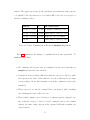
4.1
Demodulated Command in simple0 Experiment . . . . . . . . . . .
50
4.2
Demodulated Response in simple0 Experiment . . . . . . . . . . .
52
4.3
Times, Communications Events in simple0 Experiment . . . . . . .
52
4.4
Times, Communications Events in simple0x Experiment . . . . . .
53
4.5
Times, Communications Events in simple1 Experiment . . . . . . .
54
4.6
Times, Communications Events in simple3 Experiment . . . . . . .
56
4.7
Times, Communications Events in simple4 Experiment . . . . . . .
58
4.8
Times, Communications Events in simple5 Experiment . . . . . . .
59
4.9
Times, Communications Events in simple6 Experiment . . . . . . .
61
4.10 Summary of Experiments and Gap Durations . . . . . . . . . . . .
62
5.1
65
Applet on Java Card and Corresponding Gap Duration . . . . . . .
vii
List of Figures
2.1
Command APDU Structure . . . . . . . . . . . . . . . . . . . . . .
8
2.2
Response APDU Structure . . . . . . . . . . . . . . . . . . . . . . .
8
2.3
RF Modulated Data (From ISO 14443-2 [21]) . . . . . . . . . . . .
12
2.4
‘Pause’ in Reader-to-Card Communication (From ISO 14443-2 [21])
14
2.5
Decoding ISO 14443 Command (left) and Response (right) . . . . .
15
2.6
Antenna Beneath Contactless Card Surface . . . . . . . . . . . . . .
20
2.7
Close-Up of Smart Card Integrated Circuit . . . . . . . . . . . . . .
21
3.1
Activity of Microprocessor on Java Card . . . . . . . . . . . . . . .
25
3.2
Contactless Java Card Execution Model . . . . . . . . . . . . . . .
26
3.3
EM Probe Position, Side . . . . . . . . . . . . . . . . . . . . . . . .
30
3.4
Probe Far from IC . . . . . . . . . . . . . . . . . . . . . . . . . . .
31
3.5
Probe Near IC . . . . . . . . . . . . . . . . . . . . . . . . . . . . . .
31
3.6
EM Probe Position, Top . . . . . . . . . . . . . . . . . . . . . . . .
32
3.7
Card Response, Load Modulation . . . . . . . . . . . . . . . . . . .
33
3.8
Captured Frame of Modulated Data . . . . . . . . . . . . . . . . . .
36
3.9
Voltage at LED on Card Reader . . . . . . . . . . . . . . . . . . . .
39
3.10 LED Trigger, Capture 1 . . . . . . . . . . . . . . . . . . . . . . . .
40
3.11 LED Trigger, Capture 2 . . . . . . . . . . . . . . . . . . . . . . . .
40
viii
3.12 Detail of EM Trigger Condition . . . . . . . . . . . . . . . . . . . .
42
3.13 ISO 14443A Modulated Data After EM Trigger . . . . . . . . . . .
43
4.1
Configuration of Card Reader, Card, EM Probe for Experiments . .
46
4.2
EM Capture of Command Modulation, simple0 . . . . . . . . . . .
49
4.3
EM Capture of Response Modulation, simple0 . . . . . . . . . . .
51
5.1
Possible Relative Processing Time of Java Card Routines . . . . . .
66
ix
Chapter 1
Introduction
Smart cards are an embedded systems technology that are becoming entrenched
in the security-conscious computing and business landscape. The smart card is a
small plastic card containing an embedded computer system (low-power microprocessor, RAM, ROM, EEPROM, and limited I/O). Secure tamper-resistant memory
often protects sensitive information on the card, such as private keys for use in
cryptographic communications [31]. When used in a bank or credit card, these
keys are financial in nature. In GSM mobile phone Subscriber Identification Modules (SIM cards), the card securely stores the subscriber’s private identification key
used for authentication and identification on the network. In both the bank and
SIM cards, the private key is never transmitted outside the card but only used for
internal operations. Smart cards are not necessarily required by design to encrypt
or otherwise protect communications. However, in practice smart cards regularly
use cryptographic algorithms such as DES, DSA, and RSA.
A single serial communication interface is the card’s only channel for external
data exchange. The same terminal which provides the communication interface
also typically provides power to the card, though a small number of cards have
on-board power. The card only operates and executes instructions when powered,
but is inactive otherwise. In the case of smart cards with electrical contacts, a
cluster of electrical contacts provides the connections for power and serial data.
1
The contactless cards, which are powered through an electromagnetic (EM) field,
are described more fully below. Some hybrid or “dual-interface” cards support
both electrical contacts and EM operation, giving the user choice of terminal and
interface.
Smart cards adhere to a number of standards. ISO 7810 [22] defines common
form factor dimensions. ISO 7816 [20] defines electrical contacts, electrical characteristics, and communication protocols. ISO 14443 [21] (proximity cards, within
10 cm distance) defines contactless power, modulation, encoding and data formats.
While these standards define consistent card construction and low-level data interfaces, most card implementations, data formats and protocols are proprietary. A
notable exception are Java Cards [5], which execute small applications (applets)
based on a simplified Java language and environment. The Java Card specifications [35], along with Open Platform specifications [11] which often come along
with compliant cards, provide developers a standard platform and environment.
1.1
Contactless Smart Cards
Contactless smart cards, which are the focus of this thesis, are a recent variant
that provide an alternative to using electrical contacts to the outside world. The
contactless smart cards contain an antenna wound into the plastic card (shown in
Section 2.5.1), and are completely powered by the energy provided by the electromagnetic field of a nearby terminal or card reader [31]. Data is transmitted and
received over the modulated radio frequency (RF) channel. The contactless cards
no longer need any physical electrical contacts in order to operate.
While smart cards with contacts are still most prevalent, contactless cards are
currently being widely deployed. Many banks now distribute contactless smart
cards, some with a dual-contact interface for compatibility with contact terminals.
New electronic passports also use the same ISO 14443 [21] contactless communication protocol, though they are sometimes described as Radio Frequency Identi2
fication (RFID) devices due to nomenclature inconsistency. The term RFID more
commonly applies to non-cryptographic cards, supporting other ISO standards outside the scope of this thesis.
This thesis will focus on contactless smart cards which communicate using the
ISO 14443 protocol. The procedures and findings should therefore be relevant and
applicable to a very wide range of smart card-like devices which use this protocol,
including payment cards and electronic passports.
1.2
Attacks
The new applications of contactless devices, notably in payment systems and passports, will undoubtedly attract attention from malicious parties of all kinds. For
this reason, it is important to research the weaknesses of contactless systems so
that vulnerabilities can be found and corrected.
Unlike contactless cards, attacks against contact smart cards are not new. Since
Kocher’s early findings on practical timing [25] and later power analysis [26], a large
number of practical attacks have been published against various smart card implementations and algorithms. These “side-channel attacks” use extra information
obtained through a side channel (time, power consumption, electromagnetic emissions), rather than the data channel. Among these attacks, the class of differential
power analysis attacks [26] have proved to be particularly effective and difficult to
protect against, and continue to be a major research area.
However, nearly all of these attacks have targeted smart cards with electrical
contacts. When it comes to contactless smart cards, there has been surprisingly
little published research on side-channel attacks. Even within current published
research, there are few (if any) documented details on test and measurement procedures that can be used to repeat and confirm findings. This is largely due to
the confidentiality of smart card documentation, absence of platforms suitable for
academic research, and the current belief that proprietary knowledge or custom
3
hardware is required to facilitate research [16]. When proprietary hardware or
techniques are required, practical attacks can neither be properly described nor
replicated by others. Attacks against researcher-designed or modified contactless
cards are often a far cry from real world practical attacks.
The objective of this thesis is to develop research-friendly test techniques and
contactless measurement methods that can be used with unmodified, commercial
off-the-shelf equipment. The target device in this research is a commonly-used
contactless Java Card which can be programmed according to an open specification.
It is hoped that this research will open the door for further research into contactless
smart card attacks, with less proprietary hurdles than encountered up to now.
1.3
Contributions of Thesis
In the public academic research realm, there appears to be a large, unexplored
area of side-channel attacks against contactless smart cards despite ongoing smart
card research since 1995. The challenge lies with the platform, environment and
procedures used to explore attacks, which must be properly established in a nonproprietary way before sophisticated side-channel attacks can be carried out and
repeated by others in the scientific community.
The contributions of this thesis include:
• Development of a research-friendly platform suitable for further academic
research into attacks targeting contactless smart cards using ISO 14443. The
platform and environment described in this thesis uses common technologies
with public specifications (Java Card). The hardware used in the research is
not custom, but readily available at low cost.
• Software for Java Cards that demonstrates basic attack scenarios
• New measurement techniques and lab procedures for the novel environment,
4
including procedures for passive eavesdropping on ISO 14443 (contactless)
communications.
• EM-based measurements of code execution time on contactless Java Cards.
The results show the feasibility of timing attacks on Java Card applets.
• For the first time, this research shows that it is possible to monitor the EM
side-channel of a commercial off-the-shelf (COTS) contactless Java Card using a standard oscilloscope, without any card contact or custom hardware.
The findings are applicable to any device using standard ISO 14443, such as
modern payment cards and new electronic passports.
The target environment used in this thesis has not been investigated in previous contactless attack research. The protocols/standards and software used are
well documented and accessible to other researchers without proprietary concerns.
Along with fully documented test and measurement procedures, this thesis contributes a new way of researching attacks against contactless smart cards in the
hope that other researchers can build upon the platform and techniques introduced
for the first time here.
1.4
Organization of Thesis
Chapter 2 describes smart card systems including the specific contactless technology
used in this research. This background section also describes the hardware and
protocols used, as well as known attacks against these systems.
Chapter 3 describes methodology and lab preparations done before the main
experiments, which were necessary to discover and manage the novel environment.
While these experiments were preliminary and exploratory in nature, the findings
are significant as there is very little published information on experimental setups
and measurement techniques in this previously unexplored environment.
5
Chapter 4 describes the main experiments which first validate the new measurement techniques, and then correlate side-channel timing data with computations
on the smart cards. Chapter 5 discusses the experimental results and provides a
comparison to existing knowledge in the field. Chapter 6 states the contributions
of this thesis with respect to current state-of-the-art knowledge in the field and
suggests future work.
6
Chapter 2
Background
2.1
Smart Cards
Smart cards are embedded systems built into a plastic card with a standard form
factor, defined by ISO 7816 [20]. The smart card includes a low-power microprocessor, RAM, ROM, EEPROM and serial I/O (half-duplex) through either metal
contacts or an antenna, in contactless operation. Typically, smart cards do not
include a power source and are powered either through contacts or an electromagnetic field. A smart card operates when connected to a card acceptance device,
which in this thesis will be called a card reader or reader for short.
Hardware implementations of smart cards vary considerably with vendor and
microprocessor capabilities, as do programming models and software protocols. To
provide some interoperability, ISO 7816 standardizes some aspects of smart cards,
such as the external physical/electrical characteristics and the application-level protocol for data exchange.
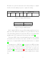
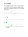
Smart cards communicate using application protocol data units, or APDUs
(defined in ISO 7816-4). These data packets take two forms: command APDUs sent
from a reader to a card, and response APDUs sent from a card back to the reader.
These packet formats are illustrated in Figure 2.1 and Figure 2.2, respectively [31].
7
The smart card operates in a master/slave model, always waiting for a command
from the reader and returning a response to complete the exchange.
Mandatory header
CLA
INS
P1
Optional body
P2
Lc
Data
Class Instruction Param1 Param2 Length Data field
Le
Response length
Figure 2.1: Command APDU Structure
Optional body
Mandatory trailer
Data field of length Le
Status word (SW)
Figure 2.2: Response APDU Structure
In the command APDU, the class byte (CLA) identifies applications and command sets, and the instruction byte (INS) encodes a specific instruction. The rest
of the packet defines parameters and optional data. There are some standard CLA
meanings, such as ‘8X’ for private use/credit cards and ‘A0’ for GSM [31].
The response APDU consists of data with length Le (specified by the command)
and a mandatory two-byte status word (or return code). There are several standard
status words, for example 0x9000 to indicate successful execution of a command
[31].
The transport protocol (ISO 7816-3 [20]) is one layer below APDU, and defines
data block formats for physical transmission. Available modes are T=0 and T=1
for contact operation. Contactless operation is called T=CL, but actually refers
to ISO 14443 [21] (described in Section 2.3). Data at the transport layer is not
encrypted, so smart card applications must encrypt communications at a higher
layer.
8
2.2
Java Cards
Java Cards are multi-application smart cards based on open standards, to facilitate
interoperability and reduce barriers to smart card software development. Smart
cards have historically been proprietary in nature and code has not been portable;
instructions written for one microprocessor could not work on another platform
without modifications.
The Java Card platform [35] aims to support multiple applications on a card
in a secure, portable environment offering many of the features of the Java programming language. Applications written for Java Card can be loaded onto cards
from different vendors, largely independent of card hardware. Security features
of Java Card such as the virtual machine, strict bounds checking, and the applet
firewall aim to prevent security breaches due to programming flaws or malicious
applications [5].
It is important to note, however, that the language used to program cards is not
Java. Only a subset of Java features are supported by Java Card. The platform
is, after all, designed for embedded systems limited by extremely low memory and
power. Some of the major differences between regular Java language and Java Card
include [5]:
• Only small primitive data types are supported. Typically, only 8 and 16-bit
integers are available [34] (hardware-dependent).
• Only one-dimensional arrays are supported. There are no strings or multidimensional arrays.
• Threads are not supported, and many complex properties of objects are not
available.
A Java Card application begins as a regular Java source file and is compiled into
a class file (as with any other Java program). The Java Card converter, running on
9
a PC, then converts this class file into a Converted Applet (CAP) file. This CAP file
contains class information, executable byte code, linking and other information in
a very compact format [5]. Although it is compact, this CAP file does not contain
machine code which can be directly executed by the smart card microprocessor.
Instead, the virtual machine on the smart card will interpret this data.
The CAP file format [35] is the standard binary format in Java Card technology.
Once a smart card application is created and converted to CAP format, it can be
loaded onto a variety of cards without much concern for underlying hardware.
Section 2.5.3 describes how these CAP files are loaded onto physical smart cards
used in this thesis.
Once the CAP file has been loaded into an actual smart card and installed, the
Java Card Virtual Machine (JCVM) interprets byte code, controls memory, and
executes microprocessor instructions. This virtual machine makes it possible to
write one Java Card application that runs on a variety of physical platforms.
The Java Card Runtime Environment (JCRE), which can generally be described
as the whole operating system (OS), consists of the virtual machine described above
as well as other APIs and system facilities. The JCRE makes it possible for independently written applications to run on the embedded system by providing an
abstract layer between application instructions and physical hardware.
Because smart cards are only externally powered when they are in use, the
JCRE (and any applications running within it) has a rather unique life cycle. The
JCRE is only initialized once during the card’s lifetime. From then on, the virtual
machine’s state as well as the state of any applications on the card are stored
in persistent memory, typically EEROM. Instances of applications, objects, and
certain allocated arrays are all stored in persistent memory. When the card’s power
is removed or interrupted, the virtual machine is suspended. When the smart card
is next powered up by connecting to a card reader, the virtual machine resumes
operation and all objects resume from their stored state.
Java Card applications are known as applets. Because cards can support mul10
tiple applets, each applet instance is assigned a unique application identifier (AID).
When a terminal wants to communicate with a specific applet, it sends the SELECT
APDU command with the appropriate AID. From Figure 2.1, which shows the command APDU encoding, the SELECT command requires CLA=0x00, INS=0xA4,
P1=0x04, P2=0x00 and the AID in the data field.
The JCRE routes the SELECT command and subsequent commands to the
appropriate applet, initializing the applet if necessary. Once the applet is selected,
commands will go to its process() method and the Java Card can be used just like
any smart card in a master/slave model.
2.3
ISO 14443 Type A
ISO 14443 [21] defines specifications for a class of contactless integrated circuit
cards (“proximity cards”) which operate at a nominal distance of approximately
10 cm, as opposed to “close coupled” or “vicinity” cards which operate at different
distances. ISO 14443 compliant cards may be called RFID cards or contactless
smart cards, depending on microprocessor capabilities.
Contactless cards are related to the Near Field Communication (NFC) standard,
operating in a passive mode and retrieving power from the RF field of a nearby
card reader [14]. The powered reader generates a sinusoidal field with carrier fc =
13.56 MHz ± 7 kHz, and supplies the card with operating energy. Both the reader
and card contain a coupling coil (loop antenna) and communicate with each other
by modulating the field. The reader and card are said to be inductively coupled,
since the electromagnetic field wavelength is several times greater than the nominal
card distance and the reader’s field can be treated as purely magnetic [23].
The standard defines two different types of cards (Type A and Type B), depending on the type of modulation used. The standard uses the terms “proximity
coupling device” (PCD) which means the card reader, and “proximity integrated
circuit card” (PICC) which means the contactless card. Throughout this thesis,
11
the simplified terms reader and card will be used, respectively.
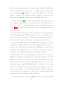
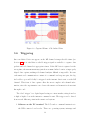
Figure 2.3 from the ISO 14443 specification illustrates data modulation in both
reader-to-card and card-to-reader communications. In this thesis, only Type A
cards are studied because the JCOP cards (used for experiments) are all Type A
[18]. The reader-to-card communications use 100% Amplitude Shift Keying (ASK)
D 14443-2: 1999(E)
© ISO/IEC
and aF Cmodified
Miller code. For this communication, the reader switches the
field
on and off, and there is no carrier during the ‘pause’ periods (described later).
7The
Signal
interface communications use load modulation and employ On/Off
card-to-reader
Two communication signal interfaces, Type A and Type B, are described in the following clauses.
Keying
(OOK) with a Manchester code. In the load modulation scheme, the card
switches an additional load into the field to draw more energy and generate a
The PCD shall alternate between modulation methods when idling before detecting the
fc
847A or
kHz.
the card and reader are coupled across the
subcarrier
= 16
presence offas PICC
of≈
Type
TypeBecause
B.
airOnly
interface,
the reader
caninterface
sense may
when
the card
its load
intountil
the field. In
one communication
signal
be active
duringswitches
a communication
session
deactivation by the PCD or removal of the PICC. Subsequent session(s) may then proceed using
Figure
this load
modulation is represented by a partial reduction in amplitude,
either 2.3,
modulation
method.
Figure 1 is
an illustration
of the concepts
described
in the following
clauses. measurements.
although
load
modulation
can appear
differently
in physical
Type A
Type B
ASK 100%
Modified Miller, 106kbit/s
ASK 10%
NRZ-L, 106kbit/s
PCD to PICC
0
PICC to PCD
1
0
0
1
Load Modulation
Subcarrier fc/16
OOK
Manchester, 106kbit/s
0
1
0
0
1
0
0
1
0
1
Load Modulation
Subcarrier fc/16
BPSK
NRZ-L*, 106kbit/s
0
1
0
1
0
* Inversion of data is also possible
Figure 1 –- Example communication signals for Type A and Type B interfaces
Figure 2.3: RF Modulated Data (From ISO 14443-2 [21])
12
In the modulation example shown in Figure 2.3, bit durations of t= 128
are
fc
marked along with decoded bit values. To illustrate the demodulation scheme,
consider each bit duration divided into two halves. The bit value will be determined
by the RF state in these two halves.
In Type A reader-to-card modulation (top left of illustration), the possible states
for the half-bits are regular carrier and ‘pause’, due to 100% ASK. The following
rules are used to demodulate the signal for each bit duration:
• ‘Pause’ at the start of the bit duration indicates logic 0 if following 0, or the
start of the communication
• Carrier in the first half-bit followed by a ‘pause’ indicates logic 1
• Carrier for the whole bit duration (both half-bits) indicates logic 0
Using the above rules, the reader-to-card RF in Figure 2.3 decodes as 01001.
In Type A card-to-reader modulation (bottom left of illustration), the possible
states for the half-bits are regular carrier and loaded subcarrier, due to the card
switching a load into the carrier (load modulation). The following rules are used
to demodulate the signal for each bit duration:
• Carrier in the first half-bit followed by loaded subcarrier in the second half-bit
indicates logic 0
• Loaded subcarrier in the first half-bit followed by carrier in the second half-bit
indicates logic 1
Using the above rules, the card-to-reader RF in Figure 2.3 decodes as 01001.
The 100% ASK used in the reader-to-card communication is characterized by a
pause in the carrier. Since the card is powered by this carrier, the pause must not
be too long. Figure 2.4 shows the specifications for this pause.
13
8 . 1 . 1 Data rate
The data bit rate for the transmission during initialization and anticollision shall be fc/128 (~ 106 kbit/s).
8 . 1 . 2 Modulation
Communication between PCD and PICC takes place using the modulation principle of ASK100%
of the RF operating field to create a “pause” as shown in Figure 2.
110%
100%
90%
Envelope of
Carrier Amplitude
H/HINITIAL
60%
t
5%
5%
Condition
t1
t2
60%
t3
t4
90%
100%
110%
Min.
Max.
2,0 us 3,0 us
t1 > 2,5 us
t1 ≤ 2,5 us
0,5 us
t1
0,7 us
0
1,5 us
0
0,4 us
t4
t2
t3
t1
.
Figure 2 -– Pause
Figure 2.4: ‘Pause’ in Reader-to-Card Communication (From ISO 14443-2 [21])
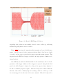
The envelope of the PCD field shall decrease monotonically to less than 5% of its initial value HINITIAL
and remain less than 5% for more than t2. This envelope shall comply to Figure 2.
Figure
2.4 shows
the field
envelope
the carrier
as it is
100% ASK.
If the envelope
of the PCD
does notof
decrease
monotonically,
themodulated
time between awith
local maximum
and the time of passing the same value before the local maximum shall not exceed 0,5 µs. This shall
only apply(tif1the
local maximum
is greater
than 5%
of HINITIAL
.
The pause
) refers
to a drop
below
90%
amplitude
of the carrier for a minimum
9
of 2.0 µs and maximum 3.0 µs before resuming a level above 5% of the carrier
amplitude.
These communications between the reader and the card are used both to transmit smart card APDU data packets, and ISO 14443 protocol-specific instructions.
ISO 14443 includes anti-collision provisions, allowing up to 14 contactless cards to
communicate with one reader. The start of a contactless card session begins with
a reader activation sequence, involving an anti-collision loop and Answer To Select
(ATS) exchange. During operation, the card reader also typically polls the card
using a REQA instruction [12].
In this thesis, the terminology used to describe smart card communications will
14
be simplified in order to focus on APDU transmissions. For example, the term
command will refer to a reader-to-card APDU communication (a request sent to
the contactless smart card), and the response will be the card-to-reader APDU
communication. The default data rate is 106 kbit/s and higher data rates may be
supported by the equipment. All experiments in this thesis are conducted at the
default data rate.
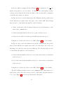
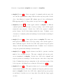
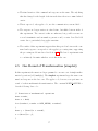
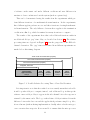
Figure 2.5 shows how ISO 14443 command and response communications can
be visually demodulated. The plot shows a Type A card communication captured
on a digital oscilloscope, using measurement techniques outlined in Section 3.4.
The x-axis is time, showing 90 µs of both the command (left) and response (right).
The y-axis is the voltage from the amplified EM probe (peak 80 mV). The binary
values above the RF waveform represent the data being transmitted, showing the
start and end of each bit duration.
Figure 2.5: Decoding ISO 14443 Command (left) and Response (right)
The demodulation rules described earlier in this section can be applied to Fig15
ure 2.5 to decode the bits. In the command (left), 100% ASK brings the signal
down near zero, forming a ‘pause’. In the response (right), load modulation appears as ‘bumps’ above the carrier. The subcarrier is not clearly observable at this
resolution, so this capture on real RF looks somewhat different than Figure 2.3.
However, it is clear where load modulation occurs and this is sufficient to demodulate the signal according to the earlier rules. As before, the two half-bit states
(aligned to the marked bit durations) are used to decode values.
The data bits are preceded by a starting marker, as described in the standard.
The eight bits are then transmitted in Least Significant Bit (LSB) to Most Significant Bit (MSB) order, plus one parity bit. Reversing the bit order, the byte is
found to be 0 0 0 0 1 0 1 1 = 0x0B.
In the experiments, this same visual demodulation technique is applied to whole
data packets in order to read data values transmitted by software. This example
from real-world communications shows that one can passively read the data bytes
in an ISO 14443 communication once a signal has been acquired with sufficient resolution. Contactless smart cards must therefore encrypt data before transmitting,
a task left to the application layer.
2.4
Known Attacks
Although the goal of this thesis is not to perform an attack on a cryptographic
system, a quick review of known attacks in the field is included here to orient the
reader to the current state of smart card attacks. The methods developed in this
thesis are more meaningful when seen in the context of existing research.
Side-channel attacks are a type of embedded system attack that have gained
much attention in recent years due to their potency and range of uses. Many, but
not all, of the attacks described in this section are side-channel attacks.
The side-channel is an avenue for acquiring extra information relevant to conducting an attack, in one of several forms:
16
• Timing, from the execution time of software routines
• Power, from current flowing through on-card circuitry
• EM emanations, from current flowing through on-card circuitry causing
electromagnetic fields
An attacker may be able to gain information from the side-channel and then
use that information to assist an attack against a target device. For instance, the
attacker may discover some bits of a key. Less direct but still dangerous, an attacker
may learn some aspect of data transformations or computations on the device such
as the state of a data bus or intermediate result.
Research into side-channel attacks began with Kocher’s timing attacks, which
revealed that careful measurements of computation time can, among other things,
reveal Diffie-Hellman exponents and factor RSA keys [25]. A few years later, a
method of analysing power consumption of a device to reveal DES secret keys was
discovered [26]. “Differential Power Analysis” (DPA) was able to easily find secret
keys from smart card power consumption and posed a serious threat to smart cards
and other embedded system. To execute these attacks, direct contact is made to
the smart card and signals can be easily acquired, unlike contactless cards.
These power attacks were based on the observation that power consumption of
a device is mathematically related to the instructions and data being processed.
Similarly, there are EM signals that emanate from an integrated circuit while it is
performing computations. These EM signals are also related to the underlying computations and can be used to obtain the same results as power analysis, now using
electromagnetic analysis (EMA) [30]. Further research showed that this EM sidechannel can reveal more information than the one-dimensional power side-channel,
and might be used to attack cryptographic devices that employ countermeasures for
power analysis [1]. Various attacks demonstrated differential EM analysis (DEMA)
on smart cards and other embedded systems [8]. However, these attacks used special purpose hardware and were not performed on contactless cards or Java Cards.
17
Contactless smart cards and RFID have recently attracted attention, as they
are now being widely deployed. Researchers have demonstrated that the same EM
attacks can work on contactless cards [3, 16], although there are very few published
attacks. There have not been any EM attacks on contactless Java Cards or other
complex multi-application cards. Some contactless cards, such as ISO 14443 [21]
compliant devices, are also vulnerable to whole new categories of relay or manin-the-middle attacks [12, 13, 24]. Researchers have been developing new tools to
demonstrate eavesdropping and other contactless threats [23, 2], which can even
be used in practical attacks against new electronic passports [15]. Further details
on how previous researchers synchronized signal acquisition with contactless smart
cards are given in Section 3.6.
Java Cards are a relatively new type of multi-application smart card that are
growing in popularity due to the ease of application development and platform compatibility. There have been some published attacks, such as using power analysis
to reverse engineer applications [38] and theoretical fault attacks [7]. Some recent
research describes methods that could be used to launch side-channel attacks [4].
There is ongoing research in our university lab relating to side-channel attacks
and countermeasures. This thesis extends some of the lab techniques introduced
by Tiu in her embedded systems side-channel attacks [37]. Gebotys and White
have also developed refinements to DEMA that make the technique usable on more
complex Java devices [10]. The devices investigated in this thesis are also Javabased and may share similar characteristics, from an EM attack perspective.
Because Java Cards and particularly contactless Java Cards are largely unexplored attack areas, this thesis sets out to discover and fully document techniques
that could be used to monitor side-channels of Java Cards and other contactless
cards.
18
2.5
Smart Card Equipment
The following is a quick overview of the smart card equipment used for this thesis. The specific smart card hardware, card reader, and software environment are
introduced.
2.5.1
JCOP Cards with NXP Processors
The contactless cards used in this thesis are Java Card Open Platform (JCOP)
cards [19], an IBM implementation of Java Card 2.1.1 [35] and Open Platform 2.0.1
[11]. The JCOP30 cards used in experiments feature a dual-interface, allowing both
regular smart card protocols T=1 and T=0 as well as the contactless T=CL over
ISO 14443A [21].
The JCOP30 card uses the Philips/NXP P8RF5016 integrated circuit [29] with
IBM’s proprietary Java Card operating system in ROM. There is 14 kB of EEPROM
available for a persistent Java heap and applets, plus an additional 512 bytes of
EEPROM for a transaction buffer. JCOP30 also offers 750 bytes of RAM for a
transient Java heap, 261 bytes of RAM for the APDU buffer, and 200 bytes for
the Java stack. A default Java Card OS from IBM is included in ROM, and an
additional 20 kB of ROM are available for applications.
Many Java Card features are optional. JCOP30 implements garbage collection
and some cryptographic algorithms (RSA, DES, SHA, MD5, key generation, random number generation). Some of these facilities are provided by the JCOP OS in
ROM while others are hardware-assisted.
The Philips/NXP P8RF5016 integrated circuit is the heart of the dual-interface
smart card. This IC includes an 8-bit low power 80C51 CPU with configurable
clock speed. The IC includes triple-DES and FameX RSA co-processors, as well as
a “true low power random number generator in hardware” [29].
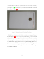
The dual-interface smart card IC is buried underneath the plastic card’s surface,
and is connected both to the metal contact pads and to an antenna for RF operation.
19
A colleague removed a thin layer of plastic from a discarded faulty card using a
power router tool [32], revealing the loop antenna wound within the card near its
edge, as shown in Figure 2.6.
Figure 2.6: Antenna Beneath Contactless Card Surface
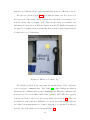
With the layer of plastic scratched off the card surface, the integrated circuit is
also visible. Figure 2.7 shows a close-up photograph of the IC, located at the same
position as the metal contact square but on the reverse side. The wire connections
to the contact pads on the reverse are visible, as are the wires connecting to the
loop antenna at the left and right. However, experiments in this thesis did not
require the removal of the IC, or any tampering of the smart card. All experiments
were carried out with an unmodified, original contactless smart card. These figures
are only shown for interest.
20
Figure 2.7: Close-Up of Smart Card Integrated Circuit
2.5.2
Card Reader
Smart cards that have no internal power source only operate together with a card
reader, which powers and communicates with the card. The card reader used in
the experiments is an Omnikey CardMan 5121 [27], an inexpensive dual-interface
card reader that connects to a PC using USB. Software on the PC uses the PC/SC
interface [28] to send and receive APDU packets to/from a card inserted into the
card reader.
The card reader supports ISO 7816 [20] for contact operation using either T=0
or T=1 transport mode. For contactless smart cards and RFID, the reader supports ISO 14443 [21] Type A and Type B cards operating at 13.56 MHz. The
reader supports up to 424 kbps data rate, but only default data rates are used in
experiments.
Different card readers may implement ISO 7816 and ISO 14443 differently. Some
of the observations in this thesis may therefore depend on the behaviour of this card
reader.
21
2.5.3
Programming Environment
The Eclipse programming environment with the JCOP Tools plug-in [17] is used to
program the cards and run experiments with applets. This development environment recognizes the card reader connected to the PC using the PC/SC interface.
The Eclipse programming environment allows regular Java programming, and the
JCOP Tools add additional libraries to support specific IBM JCOP smart cards.
The JCOP Tools also add a JCOP Shell, which can be used interactively to
send packets to a connected card reader and a smart card, if present. This allows
the programmer to directly communicate with the card reader and a smart card
through a console, showing hexadecimal/ASCII packet dumps and response packets
from the smart card.
The JCOP Shell has built-in support for the CardManager, which is an application that exists in the operating system of Open Platform/GlobalPlatform cards
[11]. The CardManager runs on the smart card and oversees application management and optional secure layers. The JCOP Shell has some commands which invoke
scripts specific to Open Platform or CardManager.
After the programmer creates a new smart card application and compiles it into
a CAP file (see Section 2.2), the following steps are used to load the applet onto
the smart card:
1. Open a JCOP Shell session to an attached PC/SC card reader
2. Use the /terminal command to poll the card reader and confirm that a card
is present
3. Use the /card command to reset the inserted card, request the answer to
reset (ATR), and select the CardManager application
4. Use the auth command to invoke an Open Platform script that authenticates,
using the default key (the key on the JCOP cards was left as default)
22
5. Use the upload command with the CAP filename as a parameter to invoke
an Open Platform script that uploads the CAP file and loads the package
using CardManager
6. Use the install command with AID parameter(s) to invoke an Open Platform
script to install the applet using CardManager. The AID will be used to
identify the new applet instance.
Once the applet instance has been created, the applet is active and ready to
receive commands. It still must be selected before use, as described in Section 2.2.
In summary, while smart cards adhere to basic standards, there is significant
variation in card design and capabilities. The low-level protocols for smart card
communication (ISO 7816 and ISO 14443) permit interoperability, but specifics
such as application protocols and implementations vary considerably. Java Cards
are a type of complex, multi-application smart card supporting a sophisticated OS
and run-time environment with many components. The Java Card adds significant
confidentiality due to OS security measures and hardware abstraction in the virtual
machine. Thus, methods for conducting research and side-channel monitoring of
such devices remain difficult with long learning curves. Previous attacks in the
smart card field have not targeted contactless Java Cards. The next section develops
an experimental setup for working with such smart cards.
23
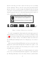
Chapter 3
Experimental Setup
3.1
Methodology
This section introduces the methodology for the investigation into contactless Java
Cards and the experiments in this thesis. A considerable amount of laboratory
work is required to establish the basic methods and procedures for dealing with
contactless Java Cards, since test and measurement procedures in this area have
not previously been documented. The required preparations, such as probe configuration and oscilloscope triggering, are described in the following sections. The novel
configuration of this test equipment and method for observing the side-channel is itself one of the thesis contributions. Section 4 then describes further experiments on
the contactless Java Cards carried out after the test methods have been established.
This thesis aims to investigate the execution of Java Card applets on contactless
smart cards from a side-channel perspective. See Section 2.4 for an introduction
to these attacks. In this thesis, only unmodified smart cards are studied so the
power analysis (from direct current flow) is ignored as a potential side-channel.
Contactless smart cards do not draw power from external wires, and any points
which carry measurable current flow are buried beneath the card’s surface.
In order to study the side-channel, one has to first locate it. Attackers are
24
interested in the time period when a smart card’s microprocessor is performing
relevant computations. There are, after all, very large time spans during which the
microprocessor is idle or possibly executing other instructions that are irrelevant
to the attacker. The attacker must therefore capture the side-channel information
during the appropriate time period, rather than during times when the smart card
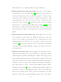
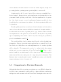
is idle, communicating, or performing other maintenance tasks.
Microprocessor activity of interest to attacker
(math computations, memory operations, etc.)
Microprocessor activity not of interest to attacker
t
Figure 3.1: Activity of Microprocessor on Java Card
To conduct a meaningful side-channel analysis, the attacker must capture sidechannel information precisely during the periods of interest as illustrated in Figure 3.1. For the time side-channel, the attacker measures the time duration of the
microprocessor activity of interest. For the EM side-channel, the attacker measures the EM signals emanating from the device during microprocessor activity of
interest.
While it is true that differential EM analysis can tolerate some amount of misalignment, the attacker must still align their side-channel data capture to some
degree. After all, in real smart cards, the irrelevant periods as depicted can last
from milliseconds to several seconds.
To conduct an attack and capture the side-channel information, the attacker
needs a trigger signal which tells measurement equipment to begin acquiring samples. This trigger must align closely to the activity of interest to permit automatic
25
capture of side-channel information.
In smart cards, the microprocessor activity of interest does not happen randomly
of course. A smart card always communicates with a terminal or card reader in
a master-slave model. The smart card waits for a command packet (an APDU as
described in Section 2.1), performs computations, and returns a response packet
(APDU). No matter what the smart card’s microprocessor does while waiting for a
command, it must perform the computations of interest after receiving a command.
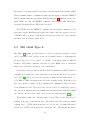
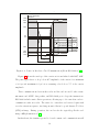
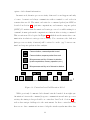
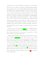
This execution model is depicted in Figure 3.2, which shows the master-slave communication in relation to microprocessor activity. For convenience, the dark area
(microprocessor activity of interest) will be referred to as the “gap” between command and response packets in later analysis.
Communication, command packet to card
Communication, response packet from card
Microprocessor activity of interest to attacker
(math computations, memory operations, etc.)
Microprocessor activity not of interest to attacker
t
Figure 3.2: Contactless Java Card Execution Model
While previously documented side-channel attacks benefited from tight synchronization between the command/response communications and microprocessor
activity, the timing is less predictable on contactless Java Cards. Section 3.2 describes these unique challenges for the environment. In these contactless cards,
there are no data communication wires to help the attacker synchronize their data
26
capture. The attacker must therefore use the RF signal in order to trigger and
capture the side-channel at the correct time.
The following sections on setting up the test environment have an emphasis on
locating RF communications for use in triggering. This will allow proper alignment
of side-channel information capture with smart card microprocessor activity. Further experiments as described in Section 4 both validate and more finely investigate
the execution model introduced by Figure 3.2.
3.2
Unique Challenges
The smart cards which have been previously attacked by researchers typically execute single code sequences and have a predictable execution sequence and timing.
For instance, the typical cryptography-capable ISO 7816 [20] smart cards contain
an 8 bit microprocessor and have one series of instructions (the program) which
executes upon receiving an input data packet (the command). They immediately
calculate the input and return a response packet.
For these conventional contact smart cards, setting up a side-channel attack is
relatively straightforward: a host computer repeatedly sends different input messages to the smart card. Wires connected to the smart card’s contacts let the
attacker measure power consumption, and direct access to the serial data contact
lets the attacker begin measurement of power or EM exactly when new data has
been sent. In this well-studied scenario, the attacker knows exactly when the code
of interest is executed.
Code execution on the Java Card is more complicated, as this is a multiapplication card. The contactless interface adds additional complications which are
described later. The Java Card operating system has a number of abstract layers
which provide interfaces between the high-level “applet” and the low-level processor
instructions. Notably, the Java Card Runtime Environment (JCRE) selects among
several applets, routes incoming commands, manages objects and memory, and does
27
garbage collection. (The JCOP30 cards used for this thesis have garbage collection
[19], others may not.) The JCRE automatically moves data to/from EEPROM as
necessary for persistent objects. The Virtual Machine (VM) interprets byte code
from the converted applet or CAP file.
The Java Card operating system therefore significantly complicates basic instruction execution, although ultimately of course simple instructions are executed
by the microprocessor. In this kind of system, it is not clear exactly which CPU
instructions are executed at which times due to lack of explicit instruction sequence
control.
Hardware implementation details of the specific Java Card OS used (IBM’s
JCOP) are unknown, as the only available documentation is a JCOP family description [18], JCOP card technical brief [19], and JCOP user guide and programming
reference [17]. The lack of low-level documentation is likely due to the security
nature of the device and the design goal of Java Card to isolate the programmer
from hardware details. In fact, so few technical details are available that many
programmers use developer forums to learn details that are not available in public
documentation [34].
Even without implementation details, it is reasonable to assume that the various
“background” operations in the Java Card OS (JCRE) lead to some unpredictability
in program execution. There may be operating system operations happening at
unpredictable intervals, which is very different from the regular single-application
smart cards. Part of this thesis aims to evaluate the actual variation in execution
times on this specific JCOP platform.
The above complications arise from the Java-related abstraction layers and runtime environment. The other major complication, in the context of setting up a
side-channel attack, comes from the purely wireless interface between the terminal and the card. Unlike the contact cards where a wire carries the data directly,
the contactless cards (including the Java Cards used in this thesis) communicate
over an RF link. The ISO 14443 [21] protocol spoken by the card and reader in28
cludes channel negotiation, data modulation, error recovery and other wireless link
provisions.
When a contactless card is placed near the reader and an RF link is established
between the terminal and the card, packets of data can be transmitted and received.
Some of these transmissions are for establishing the channel, some are idle chatter
to maintain the channel (for example REQA in ISO 14443-3 [21]) and others are of
course the modulated command and response packets of interest. The card reader’s
firmware dictates the nuances of this behaviour, making it difficult to ascertain when
actual data and not other protocol instructions are being transmitted. Add to the
picture the necessary transmit and receive buffers, and delays that come with a
USB interface to a PC terminal, and clearly it is difficult to detect exactly when
data is sent to the card.
Given these factors, the environment is particularly challenging to work with.
There is much potential for unpredictable timing and synchronization. The data
channel is littered with protocol communications which are largely irrelevant to the
data being sent to and from the applet on the card. A vital part of setting up
a side-channel attack is being able to synchronize the data acquisition from the
side-channel (for example, EM antenna voltage) with the start of processing (for
example, one encryption event). Most prior research for contactless cards have
used custom hardware of some form to provide a special synchronization signal,
undoubtedly because this synchronization of the contactless scenario is particularly
difficult to achieve.
In the experiments described in this thesis, new synchronization techniques are
attempted without the aid of custom hardware. The common card reader and
contactless card are left unmodified as they would be in a real-world attack.
29
3.3
EM Probe
Contactless smart cards are near field communication devices, and an antenna
placed in the field measures the superposition of both the modulated communication
and any side-channel emanating from the device’s microprocessor(s). This allows
passive observation of the communication channel and any side-channel emanating
from the microprocessors on the contactless device. A near field EM probe by
Electro-Metrics Inc. (Model EM-6992) connected to a pre-amplifier with typical
gain of 22 dB provides the input signal to the digital oscilloscope. The probe’s 1 cm
loop antenna is sensitive to H-field frequencies from below 100 kHz to 1 GHz. The
signal from the probe is connected with a 50 Ω coaxial cable and the oscilloscope
(see Section 3.4) is configured for matching termination. See [37] and [6] for more
details on the probe and amplifier.
Figure 3.3: EM Probe Position, Side
While the goal of this research is to set the stage for future side-channel analysis, this thesis does not consider side-channel EM measurements emanating from
contactless device microprocessors. The antenna used in these experiments is ap30
propriate for measuring near field RF signals on the 13.56 MHz modulated data
channel. Considering that the side-channel emanating from the contactless device
is far weaker than this externally powered communication field, it is important that
antennas used to measure the actual device side-channel are carefully selected and
positioned for maximum sensitivity.
For instance, the loop antenna is best positioned parallel to the chip surface for
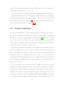
H-field measurements [3]. Figure 3.3 shows how the probe is positioned in the lab.
Figure 3.4: Probe Far from IC
Figure 3.5: Probe Near IC
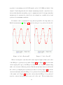
When observing the contactless field carrier signal at high resolution, the effect
of the EM probe position is very visible. Figure 3.4 and Figure 3.5 show the same
carrier signal picked up by the EM probe in the field of a reader communicating
with a card, from two different positions. Each horizontal time division is 40 ns and
the oscilloscope sampling rate is 10 GS/s (resolution of 0.1 ns). Figure 3.4 shows the
carrier measurement when the EM probe is positioned far from the metal contacts
of the smart card. Figure 3.5 shows the carrier when the EM probe is positioned
near the contacts, flat against the reverse side of the card. The two figures show
31
that there is a difference in the carrier measurement at the two different locations.
The exposed card in Section 2.5.1 shows that the smart card IC is located on
the reverse side of the metal contacts. Because the contactless card draws its power
from the carrier, this observation of the change in the carrier is potentially very
interesting as it may show an EM side-channel from the IC. Further investigation
is required to determine what is causing this effect, but the required signal analysis
is outside the scope of this thesis.
Figure 3.6: EM Probe Position, Top
The antenna position is also important for measurements of the contactless
device’s response communications. ISO 14443 [21] defines different modulation
schemes for the command and response communications. While the commands sent
from reader to card are modulated with easily observable 100% ASK, the responses
from the card back to the reader are load modulated (see Section 2.3). The load
modulation is weaker and more difficult to see, and it was found through trial and
error that best measurements are obtained when the loop antenna is positioned
near the edge of the smart card as shown in Figure 3.6.
32
Previous exploration of the smart cards used in this thesis (see Section 2.5.1)
showed that the antenna is close to the edge of the card. Therefore, the response
modulation is best observed when the EM probe’s loop antenna is placed near this
card edge with the antenna winding, as seen at the right hand side of the exposed
card in Figure 2.6. For the remainder of the experiments, the loop antenna is positioned parallel to the both the smart card and the card reader, approximately
1.0 cm above the card surface and approximately 2.5 cm above the card reader’s
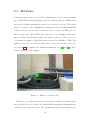
PCB surface. The centre of the probe is located on the edge of the card. Figures 3.3 and 3.6 show both dimensions of this position.
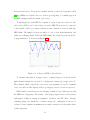
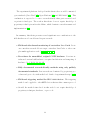
With the probe positioned in this way, the weaker response modulation becomes
easily observable. Figure 3.7 shows a card response over 40 µs (4 µs per division).
The load modulation and subcarrier described in Section 2.3 are visible.
Figure 3.7: Card Response, Load Modulation
33
3.4
Digital Oscilloscope
The primary measurement equipment used in this thesis is a Tektronix TDS7254
digital oscilloscope. Details of the equipment’s capabilities and operation can be
found in the product manual [36]. This oscilloscope, with large data storage capacity, captures and records EM signals and other inputs. The oscilloscope features
up to 6 GHz bandwidth and 20 GS/s sampling rate. The ISO 14443 carrier is fc =
13.56 MHz ± 7 kHz [21] and although the EM side-channel was not measured in
this thesis, the bandwidth of the oscilloscope is more than enough to capture the
required signal frequencies [1]. For the purpose of this thesis, measurements are
carried out with a sampling rate of 1.25 GS/s (equivalent to a resolution of 800 ps).
Real-time data acquisition is performed in regular “sample” mode (as opposed to
peak detect, average, or other modes). The amplified EM signal from the antenna is
connected to the oscilloscope with a 50 Ω termination. This input has an amplitude
< 200 mV, so the scope’s vertical axis is configured for either 50 mV or 100 mV
per division. The horizontal axis scale is adjusted according to the aspect of the
RF desired for observation. A time scale of 40 ns per division allows one to easily
observe the T =
1
13.56 MHz
= 74 ns carrier period.
Instead of single carrier periods, it is generally more useful to see subcarrier
envelopes. For these observations, a time scale of 1 to 5 µs per division allows one
to see the modulation envelope. This corresponds to the ISO 14443 subcarrier of
fs =
fc
16
≈ 847 kHz (with period ∼ 1 µs). In order to observe modulated data bits,
which is the most useful observation for demodulation and data packet analysis, a
time scale of 20 or 40 µs per division is chosen. In this range, the oscilloscope clearly
shows modulated data bits. While these time scales were adjusted through later
experiments, the acquisition sample size was also adjusted in order to maintain a
1.25 GS/s sampling rate.
34
3.5
Finding Modulated Communications
With the probe positioned for best effect and the oscilloscope configured appropriately for viewing ISO 14443 [21] communications, it is now necessary to locate
modulated data in order to refine the test and measurement techniques needed for
further testing.
As a starting point, the digital oscilloscope is configured for a simple rising edge
trigger at 0 V with a 250 ms hold-off period before the next trigger. With the
digital oscilloscope continually showing captured data (at 250 ms intervals), the
contactless smart card is inserted into the card reader’s field. The presence of the
card causes a back and forth initialization communication as per ISO 14443-3. This
communication includes both short command and response packets being sent over
RF.
Because no technique has yet been established to specifically capture these communications, the digital oscilloscope’s “fast frame” acquisition mode is used as a
search tool. Fast frame mode starts capturing many records into memory so that
each record can be individually viewed later, as if it was a separate acquisition.
Fast frame acquisition is started and then the contactless smart card is manually
inserted into the card reader’s field. Each captured frame (of 250 ms width) is then
manually observed from oscilloscope memory, until something other than unmodulated 13.56 MHz carrier is observed.
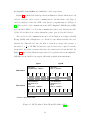
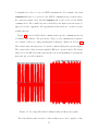
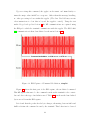
This technique gives the first view of modulated data and whole data packets.
Figure 3.8 shows one such captured frame, plotted from the oscilloscope’s frame
memory. The main display shows the 100% ASK modulation (card reader to card)
and the top display shows a wider view of this modulation, showing whole data
bits. Having obtained this view of actual modulated data, more refined triggering
techniques can now be developed.
35
Figure 3.8: Captured Frame of Modulated Data
3.6
Triggering
Since modulated data can appear on the RF channel at unpredictable times (see
Section 3.2), it is vital that a reliable trigger signal is available to capture data
packets and side-channel at appropriate times. If the RF data is captured at the
wrong time, the measurement may just show an unmodulated carrier or improperly
aligned data capture, making side-channel analysis difficult or impossible. Because
each smart card communication consists of a command and response pair, the digital oscilloscope would ideally be triggered at the instant data is sent over the RF
channel. This form of data capture offers the most complete side-channel information, since the experimenter can observe the smart card transaction from start
through to end.
The ideal “trigger” is a digital signal acting as a start marker, rising from low
to high or high to low at the instant a command is sent. The trigger can be derived
from several different points in the smart card system:
1. Software on the PC terminal. The PC sends a command instruction to
the USB-connected card reader. There are operating system, interrupt and
36
buffer delays here so no attempt is made to trigger at this stage.
2. Physical transceiver on the card reader. Once data to send is buffered
at the USB card reader, the ISO 14443 [21] transceiver on the smart card
reader sends the modulated data over RF. It is possible to directly observe
the transceiver IC’s antenna connection or digital send signal wire. This
requires physical access to the card reader, in order to connect wires to the
transceiver. Some researchers [3] have monitored the card reader’s antenna
signal as part of a contactless key-breaking attack. Others [12, 23] describe
custom hardware built to handle ISO 14443 signals, which obviously gives
the researcher most complete control with direct access to all relevant digital
signals.
3. Physical transceiver on the smart card. The modulated data is received
by the transceiver on the smart card. Unlike the transceiver on the card
reader, it is not feasible to gain physical access to this transceiver located
within the smart card, unless the card is modified or custom built. Some
researchers [16] have used a custom prototype card which has an output pin
on the microcontroller that pulls high to trigger, but custom cards are not
used in this thesis.
4. Software on the smart card. After the smart card’s hardware and operating system demodulates and decodes the RF data, it activates the software
routine (applet) responsible for handling the command. The microprocessor
starts executing instructions that process the input command. This would
be the most accurate point to trigger external side-channel measurements. If
the smart card were to support some external I/O channel for communicating a trigger signal, it could be controlled from within the applet software.
Chaumette and Sauveron [4] describe a technique using facilities available on
Java Cards to “glitch” or externally mark events. Some of these glitch techniques are not available on the JCOP cards used in this thesis, and others
which are possible offer no particular timing accuracy due to OS overhead.
37
For other Java Card implementations, the glitch techniques may provide a
useful triggering source.
5. Physical EM field. No matter what physical access to transceivers or software facilities are available, ultimately the command and response data is
transmitted through the air and can be readily observed. Instead of relying
on triggering signals obtained from modified hardware and software, a trigger derived from observation of ISO 14443 RF signals may provide the most
generic triggering. The signal obtained through the air is virtually the same
as the signal measured from a card reader antenna output, so this physical
EM approach may be functionally equivalent to an earlier method based on
monitoring the transceiver on the card reader [3]. However, that research
does not describe measurement specifics. There are no other known instances
of contactless triggering from the physical EM field.
For this thesis, triggering is first attempted from the physical transceiver on the
card reader. Further testing is performed using triggering derived from the physical
electromagnetic field, which is found to give superior results as described below.
Various techniques are attempted through trial and error, with the assistance of a
colleague who is familiar with the oscilloscope’s capabilities and EM probe [39].
3.6.1
Triggering from LED
The smart card reader used in this thesis is a commercial off-the-shelf standalone
unit as described in Section 2.5.2. While physical access to the card reader’s
printed circuit board (PCB) was easy to obtain, detailed product specifications
were not available. Without the use of proprietary data sheets, the pin out of the
RF transceiver integrated circuit was not available. However, two light emitting
diodes (LEDs) in the card reader were connected to the transceiver and preliminary
experiments showed that the LEDs blinked when data was sent and received via
RF. It was presumed that these represent Tx and Rx LEDs, common in commu38
nication transceivers. Previous side-channel attacks on embedded systems by Tiu
[37] used LEDs as a digital source for oscilloscope triggering, so a similar approach
was first attempted with the smart card reader.
To investigate use of the LED for acquisition, a pair of wires are soldered to the
card reader’s PCB to probe the voltage across the LED. These wires are connected
to the digital oscilloscope’s input channel and the channel is observed while the
LED blinks. The sampled voltage is found to be not a clean digital transition, but
rather an oscillating signal. When the LED blinks, the voltage increases from 0 V
to approximately 8 V as shown in Figure 3.9.
Figure 3.9: Voltage at LED on Card Reader
To attempt using this as a trigger source, a simple trigger is created from the
input channel using noise reject mode coupling and a rising edge trigger at 1.0 V.
The terminal, which controls the card reader, is programmed to send a command
every 4 seconds, and the digital oscilloscope triggers every 4 seconds as expected.
While initial observations were encouraging, a number of problems appear with
the LED-based triggering. The nature of the trigger signal varies between trials,
with signal oscillation varying in amplitude, duration, and DC offset. Despite
adjusting rising edge thresholds, a reliable rising edge configuration can not be
obtained. Some command transmissions are missed entirely, and other times there
is false triggering.
39
More serious problems emerge when the antenna signal is plotted alongside the
LED trigger signal. The antenna is placed in the card reader’s field and shows the
ISO 14443 [21] carrier and modulated data. For the LED-based trigger to have any
use, it must correspond precisely to a consistent point of the RF communication
(for instance, the start of the command transmission). Instead, observations reveal
that the LED voltage’s zero crossing corresponds to changing arbitrary points along
the data transmission. Figures 3.10 and 3.11 show two different LED-triggered
captures, demonstrating inconsistent alignment with modulated RF.
Figure 3.10: LED Trigger, Capture 1
Figure 3.11: LED Trigger, Capture 2
On the PC side (terminal), the automated command transmission software includes Java sleep instructions to add delays between successive sends. When the
sleep instructions are present, the LED based trigger becomes completely unusable due to seemingly random correlation to actual data transmission. Given these
numerous problems, the LED trigger approach is abandoned.
3.6.2
Triggering from EM
Triggering form the LED gave unsatisfactory results, so the physical electromagnetic field is next considered as a trigger source. For this approach, a technique
specific to ISO 14443 Type A [21] is developed. The 13.56 MHz carrier is always
present in the field, as it is needed to continually provide power to the contactless
device. This carrier is modulated only when data is being sent across the channel,
40
and command data packets are always sent first in the command/response communication sequence. Therefore, observing the first instance of data modulation after
a period of unmodulated carrier indicates the start of a command and therefore the
start of a command/response sequence. The smart card also begins its computations some time after the command transmission begins and some time before the
response transmission ends. The start of the command transmission is therefore a
very useful point at which to trigger side-channel data capture.
Part 2 of the ISO 14443 standard indicates that data communication from the
card reader to the contactless device starts with a “sequence Z” which consists
of a “pause” at the beginning of a bit duration. This provides a very convenient
condition on which to trigger, because the first “pause” after a long string of unmodulated carrier indicates the very start of a new command transmission. The
“pause” refers to a drop below 90% amplitude of the carrier for a minimum of 2.0 µs
and maximum 3.0 µs before resuming a level above 5% of the carrier amplitude, as
illustrated in Section 2.3.
The digital oscilloscope used in the lab supports a “time-out” triggering mode
which can watch for this “pause” condition [39, 36]. The digital oscilloscope is
configured to trigger when the input signal remains below 50 mV for 2 µs. The
hold-off period, during which triggers are ignored, is set to 4 ms for the tests which
are conducted over a total time of approximately 4 ms. This effectively locates the
first “pause” and therefore the start of the first command transmission.
Figure 3.12 shows pre-trigger on the left of the origin and post-trigger on the
right. The cursor position at t = -2.0 µs shows the point at which the RF signal
drops below 50 mV for the first time. At t = 0, the time-out is reached and the
oscilloscope triggers. This process very closely approximates the “pause” condition
in ISO 14443-2, illustrated earlier in Figure 2.4.
With this newly configured trigger, the same trials are performed as with the
LED trigger. The terminal is programmed to repeatedly send the same command
to the contactless device with varying delays between each transmission. The cor41
Figure 3.12: Detail of EM Trigger Condition
responding data packets are successfully observed on the oscilloscope, indicating
that this triggering method is indeed usable.
Figure 3.13 shows a typical command packet transmission observed with the new
trigger. A notable aspect of these captures is that modulated data bits are clearly
observable, and also appear exactly at the same point in subsequent captures. This
suggests that the EM-based trigger is reliable and appropriate for further sidechannel analysis.
One difficulty encountered with this method is the sensitivity to the “hold-off”
parameter of the trigger definition. Since triggers are ignored during the hold-off
period, the hold-off must be adjusted according to the expected time duration of
the whole command/response sequence. If the hold-off period is shorter than the
duration of the entire command/response exchange, then the oscilloscope would
incorrectly trigger before the start of the next command. If the hold-off period is
42
Figure 3.13: ISO 14443A Modulated Data After EM Trigger
much longer than the duration of the entire command/response exchange, the start
of the next command may be missed.
3.7
Test Harness on PC
In these preliminary experiments, the smart card reader was manually controlled.
In order to simplify further testing, a test harness is required on the PC side. A
test harness is a software tool used to automate testing of hardware/software by
subjecting it to different tests and monitoring the results for errors or failures. The
experiments in this thesis require repeated tests on several different smart card
conditions and must be automated, so a test harness will oversee the tests.
The smart card reader (see Section 2.5.2) is connected to a standard PC through
the PC/SC interface. The PC runs standard Java programs that make use of JCOP
off-card API calls [17] to communicate with the connected card reader and smart
cards which have been inserted, including contactless cards.
43
For this thesis, the smart cards will be running simple software that responds
to single incoming commands (Java code is given in Appendix A). The software
running on the PC has to send the appropriately formed command through the card
reader, and receive the response back from the smart card. The communications
are captured on the oscilloscope during this command/response transaction. The
software running on the PC performs this sequence of operations through the JCOP
Shell (described in Section 2.5.3).
1. Connect to the card reader and ensure a card is inserted (sensed via RF)
2. Send the SELECT instruction to enable the Java Card applet required for
the tests. This causes a one-time communication with the smart card.
3. Enter an infinite loop, sending command packets and checking for proper
response packets from the smart card. During this stage, the software on
the PC is communicating (over the contactless interface) with the software
loaded onto the Java Card. The oscilloscope triggers and captures these
command/response communications.
The test harness remains the same through the remaining experiments. Only
minor modifications (such as different application identifier codes) are changed
between tests.
44
Chapter 4
Experiments
This section investigates Java Card applets executing on contactless smart cards.
A number of Java Card applets are created and loaded onto a physical JCOP card
for a series of experiments on code execution. Each applet is a slight variation of a
base case, simple0. The test harness developed in Section 3.7 runs on the PC to
control the terminal, and communicates over a contactless interface with the applet
loaded on the smart card. RF communications are captured using the EM probe
triggering technique developed in Section 3.6.
For these experiments, the JCOP30 contactless Java Card is placed on top of
the USB-connected Omnikey CardMan 5121 card reader. The EM probe with
the attached 1 cm loop antenna is placed at the edge of the smart card. A rigid
apparatus keeps the card reader, card, and antenna held in place for the duration
of the measurements. Figure 4.1 shows the lab setup used for all contactless card
experiments. See the figures in Section 3.3 for more details on relative position of
devices.
The antenna is connected through an amplifier to the digital oscilloscope. See
Section 3.4 for details on the oscilloscope configuration. While the test harness on
the PC runs in a continuous loop, the smart card repeatedly answers commands
sent from the PC through the card reader using RF. Those communications are
captured and analysed.
45
Figure 4.1: Configuration of Card Reader, Card, EM Probe for Experiments
The oscilloscope is set to trigger in normal mode, so that the previously captured
waveform is frozen on the display until a new trigger condition is satisfied. As
the test harness causes continuous command packets to be sent, the display of
the oscilloscope updates with each new trial. While observing these trial-to-trial
captures, RF signals are seen to appear at the exact same time in each trial of
the experiment. The tables in the following experiments show time measurements
which are constant (not average). The one case where times shift and vary between
trials is noted in Section 4.4.
46
Overview of experiments (simple2 was renamed to simple0x)
• simple0 (Section 4.1) — Base case applet. A command packet is sent to the
card, and the applet returns a magic value in a short response packet. Results
show : demodulation of captured RF confirms expected data, validating the
EM triggering method of data packets developed in Section 3.6.
• simple0x (Section 4.2) — Same applet software as simple0. A different
command packet is sent, the same on-card processing occurs, and the applet
returns the same response. Results show : RF of the captured command
packet changes, but all other timing remains the same. Confirms correct
observation of command packets and unchanged execution time for unchanged
on-card code.
• simple1 (Section 4.3) — Same applet software as simple0. The same command packet is sent, the same on-card processing occurs, but the applet returns a different response. Results show : RF of the captured response packet
changes, but all other timing remains the same. Confirms correct observation
of response packets and unchanged execution time.
• simple3 (Section 4.4) — Applet software is modified to generate a random
number before sending response. The same command and response packets are transmitted as simple0. Results show : RF of the command and
response packets are unchanged, but the response comes after a large time
delay. Confirms that extra processing time on the card shows as time delay
before response, validating the processing model from Section 3.1.
• simple4 (Section 4.5) — The applet software now does one round of a mathematical transformation. The same command and response packets are transmitted as simple0. Results show : RF of the command and response packets
are unchanged, but there is now a longer time delay while the longer applet
executes.
47
• simple5 (Section 4.6) — The same applet software as simple4 now does
two rounds of the mathematical transformation. The same command and
response packets are transmitted. Results show : RF of the command and
response packets are unchanged, but the response comes after a further time
delay. This demonstrates that small changes in code execution show as small
extra time delays on the side-channel.
• simple6 (Section 4.7) — The same applet software as simple4 now does
three rounds of the mathematical transformation. The same command and
response packets are transmitted. Results show : RF of the command and
response packets are unchanged, but the response is further time shifted by the
same increment as when the last iteration was added. This demonstrates that
each extra round of mathematical transformation adds a uniform amount of
extra time, strongly suggesting vulnerability to a timing side-channel attack.
Taken together, the results of these experiments confirm the timing and communication model from Section 3.1, which suggest a correct and usable methodology
for investigation into the side-channel of contactless Java Cards. The results from
simple4, simple5, simple6 also suggest the feasibility of timing side-channel attacks on contactless Java Cards purely through EM observation, as discussed in
Section 5.2.
4.1
Base Case, Reference Applet (simple0)
This is the base case, and other experiments compare timing and data to this
reference. In this experiment, the terminal sends a short command, the VERIFY
(INS=0x20) instruction with blank parameters.
00 20 00 00 00
48
Upon receiving this command, the applet on the smart card immediately returns the magic value 0x2007 as a response. Other than this message handling,
no other processing is done within the applet. (The Java Card OS may execute
other instructions too but this is beyond the applet’s control.) Using the test
methodology developed in Section 3, the RF communications are captured using
the EM probe while the terminal communicates with the applet. The ISO 14443
[21] communication is then demodulated as shown in Section 2.3.
Figure 4.2: EM Capture of Command Modulation, simple0
Figure 4.2 shows the first part of the EM capture, the modulated command.
This RF signal is known to be the command sent from the terminal to the contactless card due to the type of modulation used. Table 4.1 then shows the demodulated
bytes as read from this EM capture.
It is found that the packet header byte changes, alternating between 0x0A and
0x0B each time the command is sent by the terminal. This behaviour is observed
49
throughout all experiments in this thesis and appears to be a function of the card
reader’s implementation of the the T=CL transmission protocol for contactless
communication, as described in part 4 of ISO 14443. Since the header alternates on
each transmission, and is identical in command and response, the varying header
is not explicitly mentioned in future discussions. Omitting this transport layer
header, the body of the packet is APDU protocol bytes, as described in Section 2.1.
Data Bits
Hexadecimal
Meaning
0000 1011 (alternates)
0x0B or 0x0A
T=CL packet header
0000 0001
0x01
T=CL packet header
0000 0000
0x00
APDU ‘CLA’ (class)
0010 0000
0x20
APDU ‘INS’ (instruction)
0000 0000
0x00
APDU ‘P1’ (parameter 1)
0000 0000
0x00
APDU ‘P2’ (parameter 2)
0000 0000
0x00
APDU ‘Lc’ (length of data)
1101 1101 (changes)
0xDD
Error correction code
0111 1010 (changes)
0x7A
Error correction code
Table 4.1: Demodulated Command in simple0 Experiment
Figure 4.3 shows the continuation of this EM capture, the modulated response,
after approximately 2 ms of unmodulated carrier. This response RF signal uses
load modulation because the data is sent from the contactless card back to the
terminal. Table 4.2 shows the demodulated bytes corresponding to this response
portion of the communication. The changing T=CL packet header corresponds to
the number received in the command header.
Table 4.3 summarizes the distinct parts of the RF communication: the command, unmodulated carrier, and then response. The time and duration of these
events will be compared to results from other experiments.
50
Figure 4.3: EM Capture of Response Modulation, simple0
To summarize the results of this experiment,
• The demodulated data bytes show that the observed RF does indeed represent
the command and response as transmitted within software.
• The command and response transmissions have ∼ 700 – 800 µs duration, with
a longer ∼ 2000 µs delay in between the two modulated transmissions.
• The data bytes are the expected values. These same results are seen on every
trial of this experiment.
• The observations validate the EM triggering method for capturing data packet
communications as developed in Section 3.6. The observations match the
software behaviour and the expected communications.
51
Data Bits
Hexadecimal
Meaning
0000 1011 (alternates)
0x0B or 0x0A
T=CL packet header
0000 0001
0x01
T=CL packet header
0010 0000
0x20
Byte 1 of 0x2007 response
0000 0111
0x07
Byte 2 of 0x2007 response
1001 0000
0x90
Byte 1 of 0x9000 success code
0000 0000
0x00
Byte 2 of 0x9000 success code
1101 1001 (changes)
0xD9
Error correction code
0000 1011 (changes)
0x0B
Error correction code
Table 4.2: Demodulated Response in simple0 Experiment
Interval
∆t
RF Observation
0.00 ms - 0.78 ms
0.78 ms
Command, terminal-to-card
0.78 ms - 2.72 ms
1.94 ms
Unmodulated carrier, no data
2.72 ms - 3.41 ms
0.69 ms
Response, card-to-terminal
3.41 ms -
Unmodulated carrier, no data
Table 4.3: Times, Communications Events in simple0 Experiment
4.2
Modified Command (simple0x)
The simple0x experiment runs the same applet as simple0, but with a different
command. The original command of:
00 20 00 00 00
Is replaced with
00 20 FF 00 00
This is the same VERIFY (INS=0x20) instruction, but with 0xFF in the pa52
rameter. The applet ignores the specific parameter and returns the same response
code (0x2007). The expectation is to see identical RF to the base case except for a
modified command packet.
Interval
∆t
RF Observation
0.00 ms - 0.78 ms
0.78 ms
Command, terminal-to-card
0.78 ms - 2.72 ms
1.94 ms
Unmodulated carrier, no data
2.72 ms - 3.41 ms
0.69 ms
Response, card-to-terminal
3.41 ms -
Unmodulated carrier, no data
Table 4.4: Times, Communications Events in simple0x Experiment
Table 4.4 summarizes the timing of communications in this experiment. To
summarize the results:
• The command and response data are transmitted at the exact same times as
simple0 and have the same duration.
• Comparison of the modulated RF shows that the command is different, while
the response is the same. (This difference is seen as different bit encodings
corresponding to the modified parameter byte in the command as sent by the
terminal.)
• This is expected, as only the command has been changed, with everything
else remaining the same as the base case.
• These results confirm correct observation of command packets, using the capture technique developed. Indeed, as the command sent by the terminal
changes, the same change appears in the captured RF with everything else
being identical.
53
• The results also show no change in times of communication events when there
has been no change in applet code. This suggests static communication event
timing for a fixed applet program (CAP file). This static timing is observed
on all trials, since oscilloscope plots of RF signals do not shift in time between
acquisitions.
4.3
Modified Response (simple1)
The simple1 experiment sends the same command and uses the same applet code
as the base case. However, the applet now returns the magic value 0x2008 instead
of 0x2007. It is expected that the captured EM will show identical modulated RF
data except for the response packet, which should change.
Interval
∆t
RF Observation
0.00 ms - 0.78 ms
0.78 ms
Command, terminal-to-card
0.78 ms - 2.72 ms
1.94 ms
Unmodulated carrier, no data
2.72 ms - 3.41 ms
0.69 ms
Response, card-to-terminal
3.41 ms -
Unmodulated carrier, no data
Table 4.5: Times, Communications Events in simple1 Experiment
Table 4.5 summarizes the timing of communications in this experiment. To
summarize the results:
• The command and response data are transmitted at the exact same times as
simple0 and have the same duration.
• Comparison of the modulated RF shows that the response is different, while
the command is the same.
54
• This is expected, as only the response has changed, with everything else
remaining the same as the base case.
• These results confirm correct observation of response packets. Taken together
with the simple0x results, the EM triggering technique appears to show the
correct command and response.
4.4
Random Number Generator (simple3)
In this experiment, the smart card is programmed to generate 2 bytes of random
data. The simple3 experiment keeps the same command and response as the base
case. However, the applet code now performs a more complex operation: random
number generation. The random number is computed before returning the response
code. Because of this extra strenuous computation, it is expected that there will be
a new significant time delay before the response from the contactless card is seen.
When this new applet is installed on the Java Card, it defines a random number
generator object using:
RandomData.getInstance(RandomData.ALG SECURE RANDOM);
The Java Card reference describes this ALG SECURE RANDOM type as
“cryptographically secure random number generation algorithms” as opposed to
“pseudo-random number generation” [35]. The IC referenced by the JCOP30 card
documentation also contains a “true low power random number generator in hardware” [29]. Although the specific implementation of the random number generator
is proprietary, it can safely be assumed that the random number generator is hardware assisted and at least partially based on a physical process. For instance, it
may combine a truly random component (seed generator) with a pseudorandom
component (stretching the seed into a longer number).
55
When the applet receives a command, it generates 2 bytes of random data using
the instruction:
randgen.generateData(randbytes, (short)0, RAND LEN);
Table 4.6 shows the communication time events for the card running the random
number generator. For the first time since the base case, the duration of the
unmodulated carrier changes and becomes much longer. The contactless card is
now sending its response 21 ms after the start of the communication sequence
(compared to 3 ms in the base case and previous experiments).
Interval
∆t
RF Observation
0.00 ms - 0.78 ms
0.78 ms
Command, terminal-to-card
0.78 ms - 21.21 ms (varies)
20.43 ms (varies)
Unmodulated carrier, no data
21.21 ms - 21.90 ms
0.69 ms
Response, card-to-terminal
21.90 ms -
Unmodulated carrier, no data
Table 4.6: Times, Communications Events in simple3 Experiment
On different trials of this experiment, the response modulation is seen at slightly
different times. This is unlike the other experiments (including the next three)
which always have precise times for communication events. The cryptographic
random number generator may be non-deterministic, as would be expected for
a non-pseudorandom generator based on a physical process. This would explain
varying time delays in the applet. This is purely speculation, however. It could
also be that the computation takes so much time that the Java Card OS interrupts
the execution to perform other background tasks.
To summarize these results:
56
• The time duration of the command and response are the same. The only thing
that has changed is the length of the interval where there is no unmodulated
carrier.
• This is expected; only applet code, not the communication, was modified.
• The response no longer arrives at a fixed time, but shifts between trials of
this experiment. The causes for this are unknown, but possible reasons are
a non-deterministic random number generator and/or extra Java Card OS
events due to particularly long applet run-time.
• The results of this experiment suggests that this period in between the command and response corresponds to the applet’s processing time, supporting
the processing model introduced in Section 3.1. The last 3 experiments aim
to conclusively determine whether or not this is the case.
4.5
One Round of Transformation (simple4)
In this experiment, the smart card is programmed to execute a set of simple mathematical operations (add/multiply). The simple4 experiment keeps the same command and response as the base case. The applet code, however, now performs one
round of a short mathematical transformation. The constant MATH ROUNDS =
1 in the following Java code:
// Iterations of mathematical operations
short rounds;
short x = 0xAA;
for (rounds=1; rounds <= MATH_ROUNDS; rounds++)
{
short y = (short)(x * rounds);
x = (short)(x + y);
}
57
This is a meaningless computation; the purpose is to perform some basic mathematical operations. When the card receives a command and executes these instructions, it is expected that there will be some extra delay before the response
is returned (compared to the base case). Also, it is expected that the new time
delay will be less than the simple3 case which involves a lengthy random number
generation.
Using knowledge of the processor on the smart card, it is possible to approximate the order of magnitude of the extra processing time. The P8RF5016 IC on
the JCOP30 card uses the 80C51 CPU with configurable CPU clock speed [29].
Specific implementation details are not available in the non-proprietary short specification. Assuming an 8 MHz CPU clock and approximately 20 clock cycles per
average instruction for the original Intel 8051, the average instruction executes in
approximately
1s
8·106 cycles
×
20 cycles
instruction
= 2.5 µs
There are no implementation-specific details available on how the Java code
from above is converted by the JCOP virtual machine to actual executable CPU
instructions. One might approximate on the order of 30 CPU instructions at runtime after assembly, giving a run-time on the order of 100 µs for the above code.
This calculation is very rough.
Interval
∆t
RF Observation
0.00 ms - 0.78 ms
0.78 ms
Command, terminal-to-card
0.78 ms - 3.06 ms
2.28 ms
Unmodulated carrier, no data
3.06 ms - 3.75 ms
0.69 ms
Response, card-to-terminal
3.75 ms -
Unmodulated carrier, no data
Table 4.7: Times, Communications Events in simple4 Experiment
Table 4.7 shows the measured times of the communication events. There is a
slight increase in the duration of the unmodulated carrier (2.28 ms) compared to
the base case (1.94 ms). The response is delayed by 340 µs, and this is on the same
order as the rough approximation (100 µs) for code execution time on the CPU.
58
To summarize these results:
• The command and response have the same durations and values as the base
case.
• There is a slight (340 µs) increase in the duration of the unmodulated carrier.
• Unlike simple3, this timing is constant on all trials. This may be due
to a deterministic computation (mathematical algorithm) versus the nondeterministic cryptographic random number generator used in simple3.
• The results suggest, as with simple3, that the extra delay before the response
is sent back is due to the new instructions being executed on the smart card.
This correlation is strengthened by the fact that the increase in time delay in
this experiment was on the same order as the expected code execution time,
compared to a much longer time delay in the case of the random number
generation experiment.
4.6
Two Rounds of Transformation (simple5)
The simple5 experiment keeps the same command and response as the base case.
The applet code now performs two rounds of the mathematical transformation from
simple4. Another increase in the time delay before the response is expected.
Interval
∆t
RF Observation
0.00 ms - 0.78 ms
0.78 ms
Command, terminal-to-card
0.78 ms - 3.27 ms
2.49 ms
Unmodulated carrier, no data
3.27 ms - 3.96 ms
0.69 ms
Response, card-to-terminal
3.96 ms -
Unmodulated carrier, no data
Table 4.8: Times, Communications Events in simple5 Experiment
59
Table 4.8 shows the measured times of the communication events. The unmodulated carrier duration has increased by another 210 µs compared to the experiment
with only one round of transformations.
To summarize these results:
• The command and response have the same durations and values as the base
case.
• The response arrives 210 µs later than in simple4, which had only 1 round
of transformations.
• The timing is constant for every trial.
• The result shows that a slight increase instructions executed on-card corresponds to a slight increase in duration of the unmodulated carrier observed
on the EM side-channel, before a response is sent by the card.
4.7
Three Rounds of Transformation (simple6)
The simple6 experiment keeps the same command and response as the base case.
The applet code now performs three rounds of the mathematical transformation
from simple4. Another increase in the time delay before the response is expected.
Table 4.9 shows the measured times of the communication events. The unmodulated carrier duration has increased by another 210 µs compared to the experiment
with only two round of transformations.
To summarize these results:
60
Interval
∆t
RF Observation
0.00 ms - 0.78 ms
0.78 ms
Command, terminal-to-card
0.78 ms - 3.48 ms
2.70 ms
Unmodulated carrier, no data
3.48 ms - 4.17 ms
0.69 ms
Response, card-to-terminal
-
Unmodulated carrier, no data
Table 4.9: Times, Communications Events in simple6 Experiment
• The command and response have the same durations and values as the base
case.
• The response arrives 210 µs later than in simple5, which had only two rounds.
This is in fact the same time increment as when the number of rounds was
increased from one to two.
• The timing is constant for every trial.
• The results of this series of tests on the number of rounds shows a predictable
correlation between the time shift as seen on the EM side-channel and the
code processing on-card. Each extra round of transformations computed on
the card results in an extra time delay of 210 µs in the communication. A
timing side-channel attack on this technology may be possible; see Section 5.2
for a discussion on the potential for an EM-based time side-channel attack.
4.8
Summary of Experiments
The series of test applets each yields a controlled, reproducible change in captured
EM, either in command/response data (simple0x, simple1) or the duration of the
“gap” between command and response (simple3, simple4, simple5, simple6).
These experiments use the physical EM triggering method developed in Section 3.6,
and the observations support the communication/processing model suggested in
Figure 3.2 of Section 3.1. The experimental results suggest that the EM triggering
61
method can be used to monitor the card’s side-channel, as discussed in the next
section.
Table 4.10 summarizes the contactless Java Card experiments carried out. In all
cases, the command duration is 0.78 ms and the response duration is 0.69 ms. The
command and response have a fixed byte length in all experiments, resulting in the
same number of modulated bits transmitted and therefore the same time duration.
The “gap” duration, however, changes. In all cases except for the random number
generator experiment, the measured times remain constant on all trials.
Applet executing on Java Card
Gap duration
Base Case, Reference (simple0)
1.94 ms (constant)
Modified Command (simple0x)
1.94 ms (constant)
Modified Response (simple1)
1.94 ms (constant)
Random Number Generator (simple3)
20 ms (varies)
One Round of Transformation (simple4)
2.28 ms (constant)
Two Rounds of Transformation (simple5)
2.49 ms (constant)
Three Rounds of Transformation (simple6)
2.70 ms (constant)
Table 4.10: Summary of Experiments and Gap Durations
62
Chapter 5
Discussion
The procedures for monitoring Java Card side-channels are developed to provide
necessary techniques for conducting attacks, although an actual EM side-channel
attack is not performed in this thesis. Sections 3.1 and 3.2 describe the technical
difficulties surrounding a practical EM side-channel attack on a contactless Java
Card.
Before a side-channel attack can be performed, there must be a reliable way to
determine where in time the smart card’s microprocessor is executing Java Card
applet instructions. Procedures for dealing with contactless Java Card EM signals
and ISO 14443 [21] communications are also required. In the absence of documented
procedures for these purposes, Section 3 develops new techniques for measuring the
required signals, and triggering test equipment at the proper times (see Section 3.6).
Using these new techniques and operating under an abstract model of applet
execution as depicted in Figure 3.2, the experiments set out to apply the methods
to physical Java Cards to see if the procedures work as intended. The results of
some experiments reveal additional information about contactless Java Cards that
may be useful from an EM side-channel attack perspective. The significance of
these experimental results are described below.
63
5.1
Significance of Results
One of the first challenges in this contactless Java Card side-channel research was
developing a technique to observe the RF communications which are the basis
of contactless card operation. The first experiments (Sections 4.1, 4.2, and 4.3)
validate the EM triggering method developed in Section 3.6 by demonstrating that
modifying the command and response from within software has the anticipated
effect on the captured EM signal. These experiments show that novel EM-based
triggering technique introduced in this thesis does indeed work properly with the
JCOP contactless smart card and software used in this thesis.
The rest of the experiments set out to test the abstract model of applet execution
on contactless Java Cards, as depicted in Figure 3.2. These experiments (Sections
4.4, 4.5, 4.6, and 4.7) validate the timing and processing model and support the
technique developed in this thesis for investigating side-channel attacks. These
experiments demonstrate correct location of EM measurements in time, and relative
communication and processing event times. From the results, it appears that this
thesis has answered the questions of “where” and “when” an attacker should observe
the EM side-channel in order to perform an attack.
Taken together, the experiments clearly show that passive EM measurements
are sufficient to gain some knowledge of what the contactless Java Card is processing in an applet. In all experiments, the notable feature of the EM observation
which varies is the duration of the “gap” (unmodulated carrier between command
and response). The experiments have shown that this region of the EM capture
corresponds to the smart card processor executing code, as suggested in the model
introduced in Section 3.1.
There is a correlation between the duration of this gap and the instruction cycles being executed by the contactless smart card. This correlation may be direct
or indirect, but it certainly exists. Table 5.1 summarizes the relationship between
experimentally-observed gap duration and the Java Card applet being executed during the measurement. The timings marked ‘constant’ remained constant through
64
all trials of the experiment, always appearing on the oscilloscope at the same point
in time. The one timing which varied between trials is described in more detail in
Section 4.4.
Applet executing on Java Card
Gap duration
Minimal applet, immediately returns response
1.94 ms (constant)
Applet runs 1 round of mathematical transformation
2.28 ms (constant)
Applet runs 2 rounds of mathematical transformation 2.49 ms (constant)
Applet runs 3 rounds of mathematical transformation 2.70 ms (constant)
Applet generates hardware-assisted random numbers
20 ms (varies)
Table 5.1: Applet on Java Card and Corresponding Gap Duration
From the perspective of launching a true (differential) EM analysis attack, these
results are encouraging. If the smart card’s CPU is executing applet code during
this gap between modulated command and response, then this would be the proper
time to measure the EM signals emanating from the processor. Since the smart
card can only begin executing code after the command packet is received, and must
finish execution before returning the result, it is clear that the CPU is executing the
applet code somewhere within this gap. The correlation found from the experiments
certainly supports this.
While this correlation between observed EM side-channel and applet processing
may seem obvious and expected, the specific experimental results have some serious
implications: hardware that exhibits the timing behaviour found in this thesis may
be vulnerable to an EM-based time side-channel attack.
5.2
Timing Attack Implications
Besides validating the EM side-channel observation techniques introduced in this
thesis, some of the experiments also imply the feasibility of an EM-based time sidechannel attack. In this kind of attack, the attacker measures the execution time
65
of software on the smart card under different conditions and uses differences in
run-time to draw conclusions about the system (such as a private key).
This can be demonstrated using the results from the experiments which perform different iterations of a mathematical transformation. In the experiments,
three different applets perform one, two and three iterations of a simple mathematical transformation. The only difference between these applets is the termination
condition in a for loop, which determines how many iterations to compute.
The results of the experiments show that each additional iteration results in
an additional 210 µs “gap” time delay, as described in Section 5.1. The relative
processing times are depicted in Figure 5.1 from the perspective of the EM sidechannel observation. The “gap” times as measured from different experiments are
marked above this timing diagram.
Three rounds of transformation (simple6)
Two rounds of transformation (simple5)
One round of transformation (simple4)
All applets, base case
Java Card OS /
applet overhead
1940 µs
0.00 ms
Loop
overhead
130 µs
1.94 ms
First
iteration
210 µs
2.07 ms
Second
iteration
210 µs
2.28 ms
Third
iteration
210 µs
2.49 ms
2.70 ms
Figure 5.1: Possible Relative Processing Time of Java Card Routines
It is important to note that the results do not necessarily mean that each additional loop takes 210 µs to compute; instead, each additional loop in this specific
software causes a 210 µs delay to appear in the side-channel before the response is
returned by the smart cards. The loop overhead time of 130 µs is inferred from the
difference between the base case and the applet which performs a single loop. Also,
it is not known (without having implementation details) what order the microprocessor executes these stages in. It is reasonable to assume that the microprocessor
66
executes instructions in the standard order shown in this diagram, though other
processing (such as operating system operations) likely occurs as well.
A timing attack could be carried out as follows, using an oversimplified hypothetical example. Imagine that an applet implements an algorithm which at one
point must branch depending on the value of the least significant bit of a private
key. One branch executes a series of mathematical instructions while the other
branch skips these extra instructions, similar to the thesis experiment which varies
loop iterations.
Even though the private key is securely stored inside the smart card, the attacker
can now observe the time events at the EM side-channel and determine whether or
not this branch was executed, depending on the “gap” duration. This reveals the
least significant bit of the private key to the attacker. The key has been partially
exposed, simplifying other attacks or at the very least reducing the potential key
space for an exhaustive search by 12 .
The actual feasibility of such a timing attack depends on the algorithm’s implementation. However, given that custom applications are routinely loaded onto
Java Cards, it is likely that some weak implementation of a security algorithm
will be vulnerable. The timing attack can also be combined with other existing
attacks, such as reverse engineering of Java Card applets [38]. Using a combination of methods, an attacker may be able to first reverse engineer the applet’s
instructions and then use a timing attack to compromise private information. This
illustrates why “security through obscurity” is insufficient security, even behind the
tamper-resistant protection of a smart card.
5.3
Comparison to Previous Research
Although this thesis did not perform an actual microprocessor EM side-channel attack due to time constraints, it is still possible to compare the thesis contributions
with previous work on smart cards and Java Cards. Investigations into true side67
channel attacks were obstructed by limitations of triggering accuracy and unknown
aspects of target device behaviour. For example, it is not known whether the sample
periods (as triggered) are accurate enough for EM side-channel analysis, and there
was insufficient time to investigate EM signals to this level of precision. Furthermore, the complex virtual machine on the smart card makes side-channel analysis
for this platform particularly challenging. Measurement methods developed in this
thesis provide a certain level of trigger precision and alignment, but with insufficient
time to examine the EM behaviour of the virtual machine, a complete side-channel
attack could not be pursued. Despite these limitations, the testing environment
and measurement techniques developed in this work can still be compared to past
research. Techniques for monitoring the side-channel of contactless Java Cards using EM have not previously been publicly documented. This thesis contributes new
experimental methods that can be applied to side-channel attacks for contactless
Java Cards.
Previous research on Java Card attacks ([4, 7, 38]) do not document the physical
measurement techniques required to apply such attacks to contactless cards, or
indicate whether such attacks are even relevant to the contactless case. In this
thesis, contactless cards are specifically targeted.
Leaving aside the Java Card technology, there is previous research on contactless device attacks ([12, 16, 23, 24]) but all of these require some sort of custom
hardware. The custom devices used in the experiments range from simple low cost
electronics which replicate the behaviour of simple RFID tags to fully functional
contactless prototypes manufactured with the help of commercial smart card makers. Some researchers describe generic tools that can be used for these kinds of
contactless experiments [2]. There have however been practical attacks on contactless smart cards carried out without custom hardware [3]. Still, such attacks target
simpler, single-application smart cards that don’t involve additional complications
that exist with the Java Cards used in this thesis (see Section 3.2 for a description
of these complications).
68
The experimental platform developed in this thesis relies on well documented,
open standards (Java Card [35], Open Platform [11], and ISO 14443 [21]). This
combination is expected to be more research-friendly than past research based
on private technologies. The work in this thesis does not require knowledge of
proprietary technologies such as the Mifare, which dominate contactless smart card
implementations [16].
In summary, this thesis presents several significant new contributions to the
field that have not been addressed in past research:
• EM-based side-channel monitoring of contactless Java Cards. Previous contactless research did not target contactless Java Cards or other complex multi-application cards. [2, 3, 4, 16, 23, 38]
• Procedures for unmodified, original COTS hardware. Previous attacks used custom built hardware or required modification and tampering of
hardware. [2, 3, 12, 13, 16, 23, 24]
• Fully documented research-friendly methods using only publicly
documented standards. Past research was dominated by proprietary procedures and protocols, with undisclosed details of experimental setup. [3, 4]
• EM-based triggering method for ISO 14443 devices. The triggering
method can be applied to other RFID devices that use this common protocol.
• Overall, the methods introduced in this work do not require knowledge of
proprietary techniques, hardware, or protocols.
69
Chapter 6
Conclusion
This work succeeded in developing research-friendly test techniques that can be used
with contactless Java Cards for EM-based side-channel analysis. The methods and
procedures developed in Section 3 have proved to be usable in a practical environment, at least with the JCOP-type Java Cards used in this research. Throughout
this investigation, only open standards were used and knowledge of proprietary
hardware or software was not required.
To help monitor the EM side-channel of contactless Java Cards, a method to
trigger a standard oscilloscope from an ISO 14443 [21] contactless signal was developed and tested on physical cards. Using this method, one can passively intercept
data packets by observing EM signals while the smart card is processing input. For
the first time, this research shows that it is possible to monitor the EM side-channel
of a contactless Java Card using only a standard oscilloscope and unmodified commercial off-the-shelf equipment, without any card contact or custom hardware.
The series of experiments, originally meant to investigate smart card communications and confirm the validity of measurement techniques, quickly revealed some
important relationships between observed EM signals and what the smart card is
processing. This is not an EM side-channel analysis attack (since EM was not measured from the smart card processor), but a method of reading clues about a Java
Card applet from its RF communications. Some of these findings strongly suggest
70
that a timing side-channel attack is feasible.
The very fact that EM observations alone provide some insight into executed
code is an important, novel finding. These EM signals can be observed passively
from potentially great distances, possibly opening the door for many attack scenarios. While Java Cards were used in this work because of the convenience of
programming them, it is not believed that these findings are limited to Java Cards
by any means.
It remains to be seen whether EM side-channel analysis attacks, such as differential EMA (DEMA) attacks, are possible with contactless Java Cards. This thesis
has shown that there is an observable correlation between the command/response
gap (see Section 5.1) and the code being executed by the contactless card. If usable EM side-channel information can be measured during this time window, this
thesis may play an important role leading to practical EM side-channel attacks on
contactless Java Cards.
Further research is also required to investigate vulnerability of contactless cards
to timing attacks. The environment for card configuration and EM measurement
developed in this thesis may prove to be a useful contribution for future research
in this new field.
The timing and communication model introduced in Section 3.1 is believed to be
applicable to all ISO 14443 contactless smart cards. The technique for measuring
communications and triggering by EM is believed to be applicable to all ISO 14443
RFID devices, although this thesis only experimented with Type A cards. While far
more research is needed to investigate the extent of possible attacks, it is believed
that the measurement techniques introduced in this thesis will be applicable to
bank/payment cards and electronic passports which are ISO 14443 compliant.
71
6.1
Future Work
The EM-based triggering technique developed in Section 3.6 uses a simple condition
to detect the presence of an ISO 14443 Type A [21] command signal. The trigger
condition can be further refined, either using external digital hardware or built-in
capabilities of the digital oscilloscope. A more sophisticated trigger signal can more
selectively detect the start of the desired APDU command transmission, rather than
detecting any command transmission as it currently does. (In the current form,
many other ISO 14443 protocol instructions will be detected even though they do
not mark the start of Java Card applet processing.) A simple refinement to improve
the accuracy of the EM trigger would be to ignore short command transmissions
and only trigger on commands that are longer than a predefined threshold; this
would ensure that applet-specific APDUs are being observed.
Once triggering is further refined, the microprocessor on the Java Card should be
closely inspected to see if there is an EM side-channel due to instruction execution.
Due to time constraints, the EM measured in this thesis was not analysed to detect
the presence of a microprocessor side-channel. Since no previous research existed on
measuring signals from the contactless Java Card, much time was spent developing
a suitable trigger for the new environment and refining it to become more precise.
The experiments confirm that the side-channel measurements are correctly placed
relative to each other in time, but the precision of the trigger with respect to
microprocessor activity is still unknown. Until the trigger is made very accurate,
EM side-channel measurements at high sample rates require the collection of an
extremely large number of samples. Although the digital oscilloscope used in the
experiments can store large numbers of samples, very high sample rates over even
seemingly small time intervals can produce more data than can be accommodated.
The findings from this thesis describe where in time to hunt for this EM sidechannel (see Section 5.1). Other events besides CPU cycles which may generate EM
emanations are (slower) EEPROM memory access or other data bus events. Detecting the side-channel may require selecting a different antenna (see Section 3.3)
72
or appropriately shielding the device in order to detect the comparatively weak
EM side-channel, which is normally overwhelmed by the far more powerful ISO
14443 carrier. Bandpass filtering or frequency-domain analysis may also be sufficient to detect the microprocessor EM side-channel. There has been much research
on microprocessor side-channels and EM measurement techniques [1, 30].
If an EM side-channel relating to microprocessor activity is discovered, the next
logical step is attempting to perform an actual differential EM analysis attack. A
feasible differential EM side-channel attack on the contactless Java Card would be
a significant finding. Important considerations for such an attack are:
• Does the attack work for only one target platform, or does it work on several
different implementations of “Java Cards”?
• What countermeasures exist on the target device?
• Does the attack target the (DES/RSA/etc.) coprocessor?
Other attacks not involving the EM side-channel may be possible and should
be investigated. This includes the timing side channel as described in Section 5.2.
A combination of methods may give the best results.
The test and measurement methods developed in this thesis are not limited
only to contactless Java Cards. A wide variety of bank/payment cards, electronic
passports, and other RFID cards also use ISO 14443. Potential side-channel attacks
for these important technologies should be thoroughly investigated as well.
Considering the growing importance of contactless smart cards and ISO 14443,
attack countermeasures would be another important area for future research. Contactless smart card data packets are often unencrypted, as encryption is left to the
application layer. Depending on the software developer’s design, critical portions of
data may be unprotected and easily visible (as demonstrated in Section 2.3). A recent demonstration on a European e-passport shows that this threat is not merely
academic [15]. Therefore, countermeasures such as adding noise to the physical
layer may be helpful in protecting communications [33].
73
Appendix A
Java Card Applet Source Code
package uw.minimal.simple0;
import javacard.framework.*;
public class Simple0 extends Applet {
final static short MAGIC_VALUE = 0x2007;
final static byte VERIFY = (byte)0x20;
public static void install(byte[] bArray, short bOffset, byte bLength) {
new Simple0(bArray, bOffset, bLength);
}
private Simple0(byte[] bArray, short bOffset, byte bLength){
register();
}
public boolean select(){
return true;
}
public void process(APDU apdu) {
byte[] buf = apdu.getBuffer();
if (selectingApplet()) {
return;
}
switch (buf[ISO7816.OFFSET_INS]) {
case VERIFY:
verify(apdu);
return;
// recognize VERIFY instruction
}
}
default:
ISOException.throwIt(ISO7816.SW_INS_NOT_SUPPORTED);
}
private void verify(APDU apdu){
byte[] buffer = apdu.getBuffer();
apdu.setOutgoing();
apdu.setOutgoingLength((byte)2);
Util.setShort(buffer, (short)0, MAGIC_VALUE);
apdu.sendBytes((short)0, (short)2); // return MAGIC_VALUE
}
74
List of References
[1] D. Agrawal, B. Archambeault, J. Rao, and P. Rohatgi.
The EM Side-
Channel(s). In Proceedings of Workshop on Cryptographic Hardware and Embedded Systems (CHES 2002), LNCS 2523, pages 29–45. Springer-Verlag, 2002.
17, 34, 73
[2] D. Carluccio, T. Kasper, and C. Paar. Implementation Details of a Multi
Purpose ISO 14443 RFID-Tool. In Proceedings of Workshop on RFID and
Lightweight Crypto (RFIDSec06), 2006. 18, 68, 69
[3] D. Carluccio, K. Lemke, and C. Paar. Electromagnetic side channel analysis of
a contactless smart card: First results. In Proceedings of Workshop on RFID
and Lightweight Crypto (RFIDSec05), 2005. 18, 31, 37, 38, 68, 69
[4] S. Chaumette, D., and Sauveron. An efficient and simple way to test the security of Java Cards. In WOSIS 2005, 3rd International Workshop on Security
in Information Systems, April 2005. Miami, Fl., USA, April 2005. 18, 37, 68,
69
[5] Z. Chen. Java Card Technology for Smart Cards: Architecture and Programmer’s Guide. Addison-Wesley, 2000. 2, 9, 10
[6] Electro-Metrics Inc. Near Field Probe Set Broadband Response Model EM-6992
Instruction Manual, 2002. Available at http://www.electro-metrics.com/.
30
75
[7] K. O. Gadellaa. Fault Attacks on Java Card. Master’s thesis, Eindhoven
University of Technology, 2005. 18, 68
[8] K. Gandolfi, C. Mourtel, and F. Olivier. Electromagnetic Analysis: Concrete
Results. In Proceedings of Workshop on Cryptographic Hardware and Embedded
Systems (CHES 2001), LNCS 2162, pages 251–261. Springer-Verlag, 2001. 17
[9] C. Gebotys. Design of secure cryptography against the threat of power-attacks
in DSP-embedded processors. Trans. on Embedded Computing Sys., 3(1):92–
113, 2004.
[10] C. Gebotys and B. White. A phase substitution technique for DEMA of Embedded Cryptographic systems. ITNG, pages 868–869, 2007. 18
[11] GlobalPlatform. Open Platform Card Specification 2.0.1, 2000. Available at
http://www.globalplatform.org/. 2, 19, 22, 69
[12] G. Hancke. A Practical Relay Attack on ISO 14443 Proximity Cards. Technical
report, 2005. Available at http://www.cl.cam.ac.uk/~gh275/relay.pdf.
14, 18, 37, 68, 69
[13] G. Hancke. Practical attacks on proximity identification systems (short paper).
In Proceedings of IEEE Symposium on Security and Privacy 2006, pages 328–
333. IEEE Computer Society, 2006. 18, 69
[14] E. Haselsteiner and K. Breitfuß. Security in Near Field Communication (NFC).
In Proceedings of Workshop on RFID and Lightweight Crypto (RFIDSec06),
2006. 11
[15] M. Hlavac and T. Rosa. A Note on the Relay Attacks on e-passports: The
Case of Czech e-passports. Cryptology ePrint Archive, Report 2007/244, 2007.
Available at http://eprint.iacr.org/. 18, 73
[16] M. Hutter, S. Mangard, and M. Feldhofer. Power and EM Attacks on Passive
13.56 MHz RFID Devices. In Proceedings of the Workshop on Cryptographic
76
Hardware and Embedded Systems (CHES 2007), LNCS 4727, pages 320–333.
Springer-Verlag, 2007. 4, 18, 37, 68, 69
[17] IBM. JCOP Development Tools, 2002. Available at http://www.zurich.ibm.
com/csc/infosec/jcop_tools/entry.html. 22, 28, 43
[18] IBM. JCOP Family / Versions – v. 1.1, October 2002. Available at ftp://
ftp.software.ibm.com/software/pervasive/info/JCOP_Family.pdf. 12,
28
[19] IBM. JCOP30 Technical Brief – Revision 2.5, 2002. 19, 28
[20] ISO/IEC. ISO 7816: Identification cards – Integrated circuit cards. First
edition, International Organization for Standardization. 2, 7, 8, 21, 27
[21] ISO/IEC. ISO 14443: Identification cards – Contactless integrated circuit(s)
cards – Proximity cards. Final committee draft, International Organization
for Standardization, 1999. viii, 2, 8, 11, 12, 14, 18, 19, 21, 28, 29, 32, 34, 35,
37, 40, 49, 63, 69, 70, 72
[22] ISO/IEC. ISO 7810: Identification cards – Physical characteristics. Final
draft, International Organization for Standardization, 2003. 2
[23] T. Kasper, D. Carluccio, and C. Paar. An embedded system for practical
security analysis of contactless smartcards. In Proceedings of Workshop in
Information Security Theory and Practices (WISTP07). Springer Berlin, 2007.
11, 18, 37, 68, 69
[24] Z. Kfir and A. Wool. Picking Virtual Pockets using Relay Attacks on Contactless Smartcard. In First International Conference on Security and Privacy for
Emerging Areas in Communications Networks (SECURECOMM’05), pages
47–58. IEEE Computer Society, 2005. 18, 68, 69
[25] P. Kocher. Timing Attacks on Implementations of Diffie-Hellman, RSA, DSS,
and Other Systems. In Advances in Cryptology – CRYPTO’96, LNCS 1109,
pages 104–113. Springer-Verlag, 1996. 3, 17
77
[26] P. Kocher, J. Jaffe, and B. Jun. Differential power analysis. In Advances in
Cryptology – CRYPTO’99, LNCS 1666, pages 388–397. Springer-Verlag, 1999.
3, 17
[27] OMNIKEY GmbH. CardMan 5121 Datasheet, 2005. Available at http://
omnikey.aaitg.com/. 21
[28] PC/SC Workgroup. PC/SC Workgroup Specifications, 2007. Available at
http://www.pcscworkgroup.com/. 21
[29] Philips / NXP Semiconductors. P8RF5016 - Secure Dual Interface Smart Card
IC (Short Form Specification) Revision 1.4, 2003. 19, 55, 58
[30] J. Quisquater and D. Samyde. ElectroMagnetic Analysis (EMA): Measures
and Counter-Measures for Smart Cards. In Proceedings of the International
Conference on Research in Smart Cards: Smart Card Programming and Security, LNCS 2140, pages 200–210. Springer-Verlag, 2001. 17, 73
[31] W. Rankl and W. Effing. Smart Card Handbook. John Wiley and Sons, second
edition, 2000. 1, 2, 7, 8
[32] Edgar Mateos Santillan. Discussions about JCOP equipment, August 2007.
20
[33] O. Savry, F. Pebay-Peyroula, F. Dehmas, G. Robert, and J. Reverdy. RFID
Noisy Reader: How to Prevent from Eavesdropping on the Communication?
In Proceedings of the Workshop on Cryptographic Hardware and Embedded
Systems (CHES 2007), LNCS 4727, pages 334–345. Springer-Verlag, 2007. 73
[34] Sun Developer Network (SDN). Developer Forums – Consumer and Commerce
– Java Card, 2007. Available at http://forum.java.sun.com/. 9, 28
[35] Sun Microsystems Inc. Java Card Platform Specification 2.1.1, 2000. Available
at http://java.sun.com/products/javacard/. 2, 9, 10, 19, 55, 69
78
[36] Tektronix Inc. CSA7000 Series, TDS7000 Series, & TDS6000 Series Instruments User Manual, 2003. 34, 41
[37] C. C. Tiu. A new frequency-based side channel attack for embedded systems.
Master’s thesis, University of Waterloo, 2005. 18, 30, 39
[38] D. Vermoen. Reverse engineering of Java Card applets using power analysis.
Master’s thesis, Delft University of Technology, 2006. Available at http://ce.
et.tudelft.nl/publicationfiles/1162_634_thesis_Dennis.pdf. 18, 67,
68, 69
[39] Brian A. White. Discussions about laboratory equipment and measurement
methods, June 2007. 38, 41
79