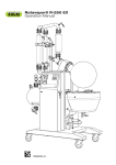
Download Rotavapor® R100 Operation Manual
Transcript
11593663 en Rotavapor® R100 Operation Manual Imprint Product Identification: Operation Manual (Original) Rotavapor® R100 11593663 en Publication date: 12.2014, Version B BÜCHI Labortechnik AG Meierseggstrasse 40 Postfach CH9230 Flawil 1 EMail: [email protected] BUCHI reserves the right to make changes to the manual as deemed necessary in the light of experi ence; especially in respect to structure, illustrations and technical detail. This manual is copyrighted. Information from it may not be reproduced, distributed, or used for competi tive purposes, nor made available to third parties.The manufacture of any component with the aid of this manual without prior written agreement is also prohibited. BÜCHI Labortechnik AG Contents Contents 1 About this document........................................................................................................... 5 1.1 1.2 1.3 1.4 Warning notices in this document........................................................................................................ 5 Symbols ............................................................................................................................................... 5 1.2.1 Warning symbols ..................................................................................................................... 5 1.2.2 Mandatory directive symbols ................................................................................................... 6 1.2.3 Other symbols.......................................................................................................................... 6 Available languages............................................................................................................................. 6 Trademarks.......................................................................................................................................... 6 2 Safety.................................................................................................................................... 7 2.1 2.2 2.3 2.4 2.5 2.6 Intended use ........................................................................................................................................ 7 Use other than that intended ............................................................................................................... 7 Staff qualification ................................................................................................................................. 8 Residual risks ...................................................................................................................................... 8 2.4.1 Dangerous vapors.................................................................................................................... 8 2.4.2 High internal pressure.............................................................................................................. 9 2.4.3 Hot surfaces and liquids........................................................................................................... 9 2.4.4 Glass breakage........................................................................................................................ 9 2.4.5 Rotating parts........................................................................................................................... 9 2.4.6 Faults during operation ............................................................................................................ 9 Personal protective equipment ............................................................................................................ 9 Modifications...................................................................................................................................... 10 3 Product description........................................................................................................... 11 3.1 3.2 Description of function ....................................................................................................................... 11 Configuration ..................................................................................................................................... 12 3.2.1 Front view .............................................................................................................................. 12 3.2.2 Rear view ............................................................................................................................... 13 3.2.3 Heating bath user interface.................................................................................................... 13 3.2.4 Typical application ................................................................................................................. 14 3.2.5 Type plate .............................................................................................................................. 15 3.2.6 Warning symbols on the device ............................................................................................. 16 Specifications supplied ...................................................................................................................... 16 Technical data ................................................................................................................................... 17 3.4.1 Rotavapor® R100 ................................................................................................................. 17 3.4.2 Heating bath B100 ................................................................................................................ 17 3.4.3 Ambient conditions................................................................................................................. 18 3.4.4 Materials ................................................................................................................................ 18 Safety features................................................................................................................................... 19 3.5.1 Overheat cutout .................................................................................................................... 19 3.5.2 Protection against electrical overload .................................................................................... 19 3.5.3 Clips and holders ................................................................................................................... 19 3.5.4 Glassware .............................................................................................................................. 19 3.5.5 Optional accessories.............................................................................................................. 19 3.3 3.4 3.5 4 Transport and storage ...................................................................................................... 20 4.1 4.2 Transport ........................................................................................................................................... 20 Storage .............................................................................................................................................. 20 Operation Manual Rotavapor® R100 iii Contents BÜCHI Labortechnik AG 5 Installation.......................................................................................................................... 21 5.1 5.2 5.3 5.4 5.5 5.6 5.7 5.8 5.9 Installation site ................................................................................................................................... 21 Mounting the rotary drive unit ............................................................................................................ 21 Fitting the vapor duct and condenser ................................................................................................ 22 Fitting the glass stopcock .................................................................................................................. 23 Connecting the vacuum and cooling media tubing ............................................................................ 24 Electrical connections ........................................................................................................................ 25 Overview of connections.................................................................................................................... 25 Setting up and filling the heating bath................................................................................................ 26 Quick check ....................................................................................................................................... 26 6 Operation............................................................................................................................ 27 6.1 Preparations ...................................................................................................................................... 27 6.1.1 Preparing the heating bath..................................................................................................... 27 6.1.2 Fitting the evaporating flask ................................................................................................... 28 6.1.3 Adjusting immersion angle of evaporating flask..................................................................... 29 6.1.4 Fitting the receiving flask ....................................................................................................... 30 6.1.5 Vertical adjustment ................................................................................................................ 30 Performing distillation ........................................................................................................................ 32 6.2.1 Raising and lowering the evaporating flask ........................................................................... 33 6.2.2 Adjusting distillation conditions .............................................................................................. 34 6.2.3 Optimization distillation .......................................................................................................... 35 6.2.4 Feeding solvent during distillation.......................................................................................... 36 Finishing distillation............................................................................................................................ 37 6.3.1 Removing the evaporating flask............................................................................................. 37 6.3.2 Removing the receiving flask ................................................................................................. 38 6.2 6.3 7 Cleaning and servicing ..................................................................................................... 39 7.1 7.2 7.3 7.4 7.5 7.6 Inspecting and cleaning the vapor duct ............................................................................................. 39 Checking the system for leaks........................................................................................................... 39 Checking seals .................................................................................................................................. 40 Cleaning the condenser..................................................................................................................... 40 Cleaning the heating bath.................................................................................................................. 41 Removing solvent accumulations ...................................................................................................... 41 8 Help with faults .................................................................................................................. 42 8.1 8.2 Faults, possible causes and remedies............................................................................................... 42 Remedy ............................................................................................................................................. 44 8.2.1 Resetting overheat safety cutout .......................................................................................... 44 8.2.2 Replacing the fuse ................................................................................................................. 45 9 Taking out of service and disposal.................................................................................. 46 9.1 9.2 Taking out of service.......................................................................................................................... 46 Disposal ............................................................................................................................................. 46 10 Appendix ............................................................................................................................ 47 10.1 10.2 Solvent table ...................................................................................................................................... 47 Spare parts and accessories ............................................................................................................. 48 10.2.1 Glass apparatus V ................................................................................................................. 49 10.2.2 Glass apparatus C ................................................................................................................. 50 10.2.3 Accessories............................................................................................................................ 51 10.2.4 Wear parts ............................................................................................................................. 55 10.2.5 Spare parts ............................................................................................................................ 56 List of abbreviations........................................................................................................................... 57 Health and safety approval ................................................................................................................ 57 Health and safety............................................................................................................................... 58 10.3 10.4 10.5 iv Operation Manual Rotavapor® R100 BÜCHI Labortechnik AG 1 About this document | 1 About this document These operating instructions describe the Rotavapor® R100 at the time supplied. They are an integral part of the product and contain important information that is nec essary for safe operation and maintenance. These operating instructions apply to all variants of the Rotavapor® R100 and are in tended primarily for laboratory staff. u To ensure safe and troublefree operation, read these operating instructions before starting up the device and follow the guidance they contain. u Keep the operating instructions somewhere near to the device. u Pass on the operating instructions to any subsequent owner or user. BÜCHI Labortechnik AG accepts no liability whatsoever for any faults or damage that result from the failure to follow these operating instructions. u If you still have any questions after reading these operating instructions, please contact BÜCHI Labortechnik AG Customer Service. Contact details for your local agents can be found on the back cover of these operating instructions or on the In ternet at http://www.buchi.com. 1.1 Warning notices in this document Warning notices warn you of dangers that can occur when handling the device. There are four danger levels, each identifiable by the signal word used. 1.2 Signal word Meaning DANGER Indicates a danger with a high level of risk which could result in death or serious injury if not prevented. WARNING Indicates a danger with a medium level of risk which could result in death or serious injury if not prevented. CAUTION Indicates a danger with a low level of risk which could result in mi nor or mediumseverity injury if not prevented. IMPORTANT Indicates a danger that could result in damage to property. Symbols The following symbols may be displayed in this instruction manual or on the device: 1.2.1 Warning symbols Symbol Operation Manual Rotavapor® R100 Meaning Symbol Meaning General warning Corrosive substance Dangerous electrical voltage Flammable substance Biological hazard Potentially explosive atmos phere Breakable items Dangerous gases 5/60 1 | About this document BÜCHI Labortechnik AG Symbol 1.2.2 Symbol Meaning Hot surface Healthharming or irritant substances Risk of hand injury Strong magnetism Mandatory directive symbols Symbol 1.2.3 Meaning Meaning Symbol Meaning Wear safety goggles Wear protective clothing Wear protective gloves Heavy load, do not lift without assistance Other symbols NOTE This symbol draws attention to useful and important information. R This character draws attention to a requirement that must be met before the in structions below are carried out. u This character indicates an instruction that must be carried out by the user. 5 This character indicates the result of a correctly carried out instruction. 1.3 Available languages These operating instructions were originally produced in German and have been translated into several other languages. The translations are available on the enclosed CD or can be obtained as a PDF file via http://www.buchi.com. 1.4 Trademarks Product names and registered or unregistered trademarks that are used in this instruc tion manual are used only for identification and remain the property of the owner in each case. Rotavapor® is a registered trademark of BÜCHI Labortechnik AG. 6/60 Operation Manual Rotavapor® R100 BÜCHI Labortechnik AG Safety | 2 2 Safety 2.1 Intended use The Rotavapor® R100 is intended for evaporating and condensing solvents. It can be used in laboratories and production facilities for the following operations: Evaporating and condensing solvents and suspensions Synthesis and purification of refined chemicals Recycling and concentration of solvents Recrystallization Drying of powders and granulates 2.2 Use other than that intended Use of any kind other than that described in the section Chapter 2.1 "Intended use", page 7 and any application that does not comply with the technical specifications (see Chapter 3.4 "Technical data", page 17) constitutes use other than that intended. In particular, the following applications are not permissible: Use of the device in an environment with a potential risk of explosion or areas which require explosionsafe apparatus Use of the device for processing substances in the food, animal feed or cosmetics industries Production and processing of substances that can lead to spontaneous reactions, e.g. explosives, metal hydrides or solvents that can form peroxides Working with explosive gas mixtures Distillation of oil Drying hard, brittle substances (e.g. stone or soil samples) that could damage the evaporating flask Shockcooling of the evaporating flask or other glass components Damage or hazards attributable to use of the product other than as intended are en tirely at the risk of the user alone. Operation Manual Rotavapor® R100 7/60 2 | Safety BÜCHI Labortechnik AG 2.3 Staff qualification Unqualified persons are unable to identify risks and are therefore exposed to greater dangers. The device may only be operated by suitably qualified laboratory staff. These operating instructions are aimed at the following target groups: Users Users are persons that meet the following criteria: They have been instructed in the use of the device. They are familiar with the contents of these operating instructions and the applica ble safety regulations and apply them. They are able on the basis of their training or professional experience to assess the risks associated with the use of the device. Operator The operator (generally the laboratory manager) is responsible for the following as pects: The device must be correctly installed, commissioned, operated and serviced. Only suitably qualified staff may be assigned the task of performing the operations described in these operating instructions. The staff must comply with the locally applicable requirements and regulations for safe and hazardconscious working practices. Safetyrelated incidents that occur while using the device should be reported to the manufacturer ([email protected]). BUCHI service technicians Service technicians authorized by BUCHI have attended special training courses and are authorized by BÜCHI Labortechnik AG to carry out special servicing and repair measures. 2.4 Residual risks The device has been developed and manufactured using the latest technological ad vances. Nevertheless, risks to persons, property or the environment can arise if the device is used incorrectly. Appropriate warnings in this manual serve to alert the user to these residual dangers. 2.4.1 Dangerous vapors Distillation can produce dangerous vapors that are capable of causing lifethreatening toxic effects. Do not inhale any vapors produced during distillation. Ensure that vapors are removed immediately by a suitable fume hood. Only use the device in well ventilated areas. If vapors escape from joints or connections, check the seals concerned and re place them if necessary. u Do not distill any unknown fluids. u Observe the safety data sheets for all fluids used. u u u u 8/60 Operation Manual Rotavapor® R100 BÜCHI Labortechnik AG 2.4.2 Safety | 2 High internal pressure The evaporation of fluids can produce high pressures inside the flask or the con denser. If that pressure becomes too great, the glass components could explode. u Make sure that the internal pressure inside the glass components is never greater than atmospheric pressure. u When distilling without a vacuum, set the vacuum pump to atmospheric pressure so that excess pressure is automatically dissipated. u If a vacuum pump is not used, leave the vacuum connection open. 2.4.3 Hot surfaces and liquids The heating bath, evaporating flask and parts of the condenser can become very hot. If touched they can cause skin burns. u Do not touch hot surfaces or liquids or else wear suitable protective gloves. 2.4.4 Glass breakage Broken glass can cause severe cuts. Damaged glass components may implode if subjected to a vacuum. Minor damage to the ground joints impairs the sealing effect and may therefore reduce diminish distillation capacity. u Handle the flask and other glass components carefully and do not drop them. u Always place the flasks in a suitable holder when they are not mounted on the Ro tavapor. u Always visually inspect glass components for damage every time they are to be used. u Do not continue to use glass components that are damaged. u Always wear protective gloves when disposing of broken glass. 2.4.5 Rotating parts The evaporating flask and the vapor duct are rotated by the rotary drive unit. Hair, clothing or jewelry can become caught up if allowed to come into contact with the ro tating parts. At high speeds, the heating fluid may be sprayed out by the rotation of the evaporating flask. u u u u u 2.4.6 Wear work overalls or protective clothing. Do not wear loose or baggy items of clothing such as scarves or neckties. Tie up long hair. Do not wear jewelry such as necklaces or bracelets. At high speeds and/or high temperatures, use the optional safety guard or a similar protective arrangement. Faults during operation If a device is damaged, sharp edges or exposed electrical wires can cause injuries. u Regularly check device for visible damage. u If faults occur, switch off the device immediately, unplug the power cord and inform the operator. u Do not continue to use devices that are damaged. 2.5 Personal protective equipment Depending on the application, hazards due to heat and/or corrosive chemicals may arise. Operation Manual Rotavapor® R100 9/60 2 | Safety BÜCHI Labortechnik AG u Always wear appropriate personal protective equipment such as safety goggles, protective clothing and gloves. u Make sure that the personal protective equipment meets the requirements of the safety data sheets for all chemicals used. 2.6 Modifications Unauthorized modifications may impair safety and lead to accidents. u Use only genuine BUCHI accessories, spare parts and consumables. u Technical modifications to the device or accessories should only be carried out with the prior written approval of BÜCHI Labortechnik AG and only by authorized BUCHI technicians. BUCHI accepts no liability whatsoever for damage arising as a result of unauthorized modifications. 10/60 Operation Manual Rotavapor® R100 BÜCHI Labortechnik AG Product description | 3 3 Product description 3.1 Description of function The Rotavapor® R100 is a rotary evaporator with the aid of which singlestage distil lation can be carried out quickly without unduly stressing the product. The basis of the process is the evaporation and condensing of solvents using a rotating evaporating flask under vacuum. Distillation under vacuum increases capacity and is more gentle on the product. The product is heated in the evaporating flask by the heating bath. The rotary drive unit evenly rotates the evaporating flask. This constantly mixes the product, thereby increasing the evaporation rate. Rotation also prevents localized overheating and de layed evaporation. The vapor passes from the evaporating flask through the vapor duct into the cooling section (condenser). There, the thermal energy of the vapor is transferred to the coolant fluid so that the vapor recondenses. The resulting solvent is collected in the receiving flask and can then be reused or properly disposed of. Distillation under vacuum The distillation capacity depends on the temperature of the heating bath, the pressure in the evaporating flask, the speed of rotation and the size of the evaporating flask. Lower pressure, i.e. more vacuum, reduces the boiling point of the solvent so that it requires less heating. That means that it can be distilled more gently and at a faster evaporation rate than processes carried out under normal ambient conditions. To prevent undesirable solvent emission and delayed evaporation, the vacuum has to be adjusted to suit the application and kept stable. This can be achieved by means of a vacuum pump (we recommend the BUCHI Vacuum Pump V100) controlled by a vacuum regulator (we recommend the BUCHI Interface I100). We also recommend that the temperature difference between the coolant fluid and the heating bath is 40 °C (see Chapter 6.2.2 "Adjusting distillation conditions", page 34). Operation Manual Rotavapor® R100 11/60 3 | Product description BÜCHI Labortechnik AG 3.2 Configuration 3.2.1 Front view 13 Fig. 1: Configuration of R100 with Vcondenser 1 Condenser 9 Rotary drive unit 2 Glass stopcock 10 Combiclip 3 Solvent feeding 11 Evaporating flask 4 Power supply for rotary drive unit 12 Heating bath 5 Receiving flask 13 Master switch 6 Handle for height adjustment 7 Lower vertical stop 8 Vertical operating range adjuster Fig. 2: Rotary drive unit 12/60 1 Rotation speed control 3 Rotary drive locking button 2 Immersion angle locking lever 4 Combiclip Operation Manual Rotavapor® R100 BÜCHI Labortechnik AG 3.2.2 Product description | 3 Rear view Fig. 3: Rear view R100 1 Power supply connection 3 Vacuum connection 2 Fuse 4 Coolant fluid connection 5 Power supply for rotary drive unit 3.2.3 Heating bath user interface 4 Fig. 4: Heating bath user interface 1 Temperature display 3 Master switch 2 Heating process indicator (dot) 4 Adjustment buttons Operation Manual Rotavapor® R100 13/60 3 | Product description 3.2.4 BÜCHI Labortechnik AG Typical application In order to use the Rotavapor® R100 to best effect, we recommend that it is used to gether with the following peripheral devices: Recirculating Chiller F-100 Fig. 5: Rotavapor® R100 system 1 Recirculating Chiller F100/F105 2 Rotavapor® R100 3 Vacuum Pump V100 with Interface I100 The Vacuum Pump V100 is designed for evacuating laboratory apparatus with the aid of a PTFE membrane. It can be operated either as a standalone device or combined with optional accessories such as an interface unit and a secondary condenser to form a complete vacuum system. The F100 and F105 are sealedsystem recirculating chillers. They are available in various capacity ratings. 14/60 Operation Manual Rotavapor® R100 BÜCHI Labortechnik AG 3.2.5 Product description | 3 Type plate The type plate is on the righthand side of the Rotavapor® R100. BUCHI Operations India Pvt Ltd 394230 Surat / India Type: R-100 SN: 1000000000 Volt: 100 – 240 VAC Frequ.: 50/60 Hz Power: 210 W Built: 2014 Designed by BUCHI in Switzerland, Made in India 1 2 3 4 5 6 7 8 9 11 10 Fig. 6: Type plate (example) 1 Company name and address 7 Year of manufacture 2 Device name 8 Country of manufacture 3 Serial number 9 Approvals 4 Input voltage 10 Symbol for "Do not dispose of as household waste" 5 Frequency 11 Product code 6 Maximum power rating Operation Manual Rotavapor® R100 15/60 3 | Product description BÜCHI Labortechnik AG 3.2.6 Warning symbols on the device The device carries the following warning symbol: 3.3 Specifications supplied System with glassware System without glass ware Rotavapor® R100 1 1 Heating bath B100 1 1 Condenser (as per order number) 1 – Vapor duct (with combiclip) 1 – Vacuum seal (KD22) 1 1 Evaporating flask (1 litre) 1 – Receiving flask (1 litre) 1 – Solvents table flyer 1 1 1 set – 1 1 Required coolant and vacuum tubing Power cord 16/60 Operation Manual Rotavapor® R100 BÜCHI Labortechnik AG Product description | 3 3.4 Technical data 3.4.1 Rotavapor® R100 3.4.2 Dimensions (W x H x D) 617 x 898 x 502 mm (inc. condenser and heating bath) 480 x 626 x 502 mm (w/o condenser and heating bath) Weight 18 – 19 kg (depending on glassware included) Voltage 24 V DC Power consumption 30 W Enclosure rating IP21 Immersion angle 0 – 35° Adjustable height 150 mm (+ 100 mm optional extension) Rotation speed 20 – 280 rpm Flask size 50 – 4000 mL Max. flask capacity 3 kg Approval CE Heating bath B100 Dimensions (W x H x D) 285 x 219 x 326 mm Weight 3.9 kg Voltage 100 – 120 V/220 – 240 V Frequency 50 – 60 Hz Power consumption 1700 W Heater output 1300 W Enclosure rating IP21 Fuse T 12.5 A L 250 V (100 – 120 V) T 6.3 A L 250 V (220 – 240 V) Temperature range 20 – 95 °C Max. flask size 4000 mL Adjustment accuracy ± 1 % Bath capacity 4 L High temperature cutout > 145 °C Approval CE Operation Manual Rotavapor® R100 17/60 3 | Product description 3.4.3 BÜCHI Labortechnik AG Ambient conditions Max. altitude above sea level 2000 m Ambient temperature 10 – 40 °C Maximum relative humidity 80 % for temperatures up to 31 °C decreasing linearly to 50 % at 40 °C The Rotavapor® may only be used in indoor areas. 3.4.4 18/60 Materials Component Material Rotavapor housing Anodized aluminium with powder coating Heating bath housing PBT, partially glassfiber reinforced Heating bath Stainless steel 1.4404, glasspeened Safety guard Polycarbonate Guard ring (of safety guard) PBT, partially glassfiber reinforced Rotary drive unit Stainless steel 1.4305 Flange connection to condenser Aluminium Seal NBR, PTFE Operation Manual Rotavapor® R100 BÜCHI Labortechnik AG Product description | 3 3.5 Safety features 3.5.1 Overheat cutout To protect against overheating, the heating bath has a thermostatic bath temperature control. In addition it is fitted with an electronic and a mechanical overheat cutout. The electronic overheat cutout monitors the temperature limit (the actual temperature of the bath must not exceed the specified temperature by more than 2 °C for longer than 2 minutes) the heating rate ( the actual temperature must not increase by more than 5 °C within 5 seconds) and the function of the temperature sensor. If the elec tronic overheat cutout trips, the device should be inspected by a BUCHI service tech nician. The mechanical overheat cutout consists of a bimetallic thermostat that immediately cuts off the power supply at high temperatures (above 145 °C). The mechanical over heat cutout has to be manually reset once the heating bath has cooled down (see Chapter 8.2.1 "Resetting overheat safety cutout", page 44). 3.5.2 Protection against electrical overload The heating bath is equipped with fuses to protect against electrical overload. The rotary drive unit has an electrical overload cutout. 3.5.3 Clips and holders Combiclips for fixing the evaporating flask and safe release of sticking ground glass joints Ball joint clamps for securely fixing the receiving flask Laboratory stand and holder for fixing glass apparatus Cap nut for fixing the condenser 3.5.4 Glassware Highquality borosilicate glass 3.3 GL14 hose barbs for preventing glass breakage 3.5.5 Optional accessories Safety guard to protect user against glass splinters, solvent splashes or hot heating fluid in the event of accidents or implosions Laboratory stand for providing additional fixing for condenser (see Chapter 10.2 "Spare parts and accessories", page 48) Operation Manual Rotavapor® R100 19/60 4 | Transport and storage BÜCHI Labortechnik AG 4 Transport and storage 4.1 Transport IMPORTANT Risk of breakage due to incorrect transportation u Make sure that the device is fully dismantled and all parts of the device are safely packed in such a way as to prevent breakage, ideally in the original box. u Avoid sharp movements during transit. u After transportation, check the device and all glass components for damage. u Damage that has occurred in transit should be reported to the carrier. u Keep packing for future transportation. 4.2 Storage u Make sure that the ambient conditions are complied with (see Chapter 3.4 "Techni cal data", page 17). u Wherever possible, store the device in its original packaging. u After storage, check the device, all glass components, seals and tubing for damage and replace if necessary. 20/60 Operation Manual Rotavapor® R100 BÜCHI Labortechnik AG Installation | 5 5 Installation 5.1 Installation site The installation site must meet the following requirements: Firm and level surface Space requirements: at least 620 mm x 510 mm (W x D) If distilling under vacuum, there must be a fume hood available. Wherever possible, the Rotavapor® R100 should be set up inside the fume hood. If that is not possible for reasons of space, it can also be set up outside if the safety guard (optional accessory) is fitted and the residual vapors are fed into the fume hood. 5.2 Mounting the rotary drive unit IMPORTANT Risk of property damage due to rotary drive unit falling off u Make sure that the screw for fixing the rotary drive unit engages securely in the groove in the tower mount. u Slide rotary drive unit (2) onto the tower mount (1). u Tighten screw (4) to lock the rotary drive unit in the groove (3) so that it cannot be pulled off. u Tighten the locking lever (5) for the immersion angle. u Check that the rotary drive unit cannot be pulled off or twisted. Operation Manual Rotavapor® R100 21/60 5 | Installation BÜCHI Labortechnik AG 5.3 Fitting the vapor duct and condenser 1 2 2 3 4 u Insert vapor duct (4) into the rotary drive unit. The vapor duct snaps into place with an audible click. u NOTICE! Risk of seal damage if fitted incorrectly. Insert seal (2) into the flange of the condenser (1) as shown. u Fit condenser (1) into the rotary drive unit, keeping it straight as you do so. When doing so, make sure that the inner lip of the seal (2) does not fold over as the seal would then be destroyed. u Tighten the cap nut (3) to fix the condenser in position. When doing so, make sure that the spring clip in the cap nut completely encircles the neck of the condenser. 22/60 Operation Manual Rotavapor® R100 BÜCHI Labortechnik AG 5.4 Installation | 5 Fitting the glass stopcock Materials required: Grease Glisseal 40 blue (order number 048197) u Connect a supply tubing for solvent (2). u Apply a thin coat of Grease Glisseal 40 blue to the glass stopcock (1). u Insert glass stopcock into the condenser and turn to the desired position. The glass stopcock performs various functions depending on its position: Glass stopcock handle pointing forwards or backwards: the system is sealed. This is the standard position for distillation. Glass stopcock handle pointing upwards: system is being vented. Glass stopcock handle pointing downwards: additional solvent can be fed into the evaporating flask via a connected feeding tubing. Operation Manual Rotavapor® R100 23/60 5 | Installation BÜCHI Labortechnik AG 5.5 Connecting the vacuum and cooling media tubing To achieve optimum distillation, all devices in the system should be matched to one another. Therefore, we recommend that the Rotavapor® R100 is used together with the BUCHI Vacuum Pump V100 and the BUCHI Recirculating Chiller F100 or F105 (see Chapter 3.2.4 "Typical application", page 14). u Connect cooling media tubes to the two coolant connections (2) and (3) using GL14 cap nuts. There is no need to distinguish between flow and return when do ing so. u Connect the vacuum tubing to the vacuum connection (1) using a GL14 cap nuts. 24/60 Operation Manual Rotavapor® R100 BÜCHI Labortechnik AG 5.6 Installation | 5 Electrical connections u Make sure that the available power supply matches the rating indicated on the type plate. u Plug the rotary drive unit connecting lead into the socket (2) on the heating bath. u Plug the power cord into the socket (1) on the heating bath and then into a mains power socket. u If an extension lead is required, make sure that it is earthed and has a suitable power rating. 5.7 Overview of connections The diagram below shows the connection of tubing and electrical leads in a typical ap plication of the Rotavapor® R100 in conjunction with a Recirculating Chiller F105, a Vacuum Pump V100, an Interface I100 and a Woulff bottle (see also Chapter 3.2.4 "Typical application", page 14). IN OUT The connections to the Recirculating Chiller F105, the Vacuum Pump V100 and the Interface I100 are described in the particular operating instructions in each case. Operation Manual Rotavapor® R100 25/60 5 | Installation BÜCHI Labortechnik AG 5.8 Setting up and filling the heating bath 1 2 u Locate the heating bath (1) in the Lshaped cutout in the Rotavapor base (2). IMPORTANT Risk of heating bath corrosion due to use of unsuitable heating fluid u Do not use pure distilled water or deionised water. u If pure distilled or deionised water has to be used, add 1 to 2 g of Borax (Na2B4O7 x 10 H2O) per litre of water. The recommended fluid for use in the heating bath is water. Normal tap water may be mixed with distilled water with a mixing ratio of up to 1:1 according to the water hard ness. u Fill the heating bath with suitable fluid. 5.9 Quick check u To complete the installation process, check the following points: u Switch on the rotary drive unit, change the rotation speed and check that the evap orating flask rotates at a different speed. u CAUTION! Risk of skin burns. Make sure that the heating bath is filled, switch on the heating bath and check that the heating fluid heats up (Chapter 6.1.1 "Prepar ing the heating bath", page 27). u Check that the height of the rotary drive unit can be adjusted (see Chapter 6.1.5 "Vertical adjustment", page 30). 26/60 Operation Manual Rotavapor® R100 BÜCHI Labortechnik AG Operation | 6 6 Operation 6.1 Preparations 6.1.1 Preparing the heating bath CAUTION Risk of skin burns from hot fluids and surfaces u Do not put your hands in the hot fluid. u Do not carry, shift, tip or otherwise move the heating bath when it is filled with hot fluid. u Do not fill the heating bath right to the very top. Allow for the expansion of the fluid when heated. u Do not switch on the heating bath when it is empty. CAUTION Using oil as a heating fluid Risk of skin burns from oil splashes u Never pour water into hot oil. u Make sure that the oil used is suitable for these purposes. 4 u Make sure that the heating bath is filled. u Switch on the device at the master switch (3). The heating bath temperature last set is displayed. u Set the desired temperature using the adjustment buttons (4). The set temperature (1) flashes during adjustment. Afterwards, the current actual temperature is indicated and the heater switched on. Operation Manual Rotavapor® R100 27/60 6 | Operation BÜCHI Labortechnik AG 6.1.2 Fitting the evaporating flask IMPORTANT Risk of evaporating flask damage if fitted incorrectly u When fitting the evaporating flask make sure that the edge of the glass does not strike the vapor duct. u Tighten combiclip no more than handtight. u Carefully fit evaporating flask (3) onto the vapor duct (2). u Slide clip (4) over the neck of the flask. u Screw combiclip (1) clockwise until handtight. 28/60 Operation Manual Rotavapor® R100 BÜCHI Labortechnik AG 6.1.3 Operation | 6 Adjusting immersion angle of evaporating flask u Switch off the Rotavapor on the heating bath. u Hold the condenser (1) firmly with one hand and release the lever (2) with the other hand. u Adjust the immersion angle. u Lock the rotary drive unit in position again with the lever (2). u Make sure that there is at least 10 mm clearance between the edge of the heating bath and the evaporating flask or vapor duct. To achieve that, adjust the height of the rotary drive unit if necessary (see Chapter 6.2.1 "Raising and lowering the evaporating flask", page 33). u Check the vertical end stop and adjust if necessary (see Chapter 6.1.5 "Vertical ad justment", page 30). Operation Manual Rotavapor® R100 29/60 6 | Operation BÜCHI Labortechnik AG 6.1.4 Fitting the receiving flask Materials required: Grease Glisseal 40 blue (order number 048197) u Apply a thin coat of Grease Glisseal 40 blue to the ground joint of the receiving flask. u Fit the receiving flask (3) onto the condenser from below and secure it with the ball joint clamp (2). 6.1.5 Vertical adjustment 1 2 3 The rotary drive unit together with the glass components can be raised or lowered in the following ways: Using the handle (1), the evaporating flask can be lowered into and lifted out of the heating bath (see Chapter 6.2.1 "Raising and lowering the evaporating flask", page 33). To prevent the evaporating flask and the vapor duct from colliding with the heating bath, a lower stop can be set using the screwhandle (2). If an especially large evaporating flask or a long vapor duct is being used, the entire vertical adjustment range can be moved up or down by means of screwhandle (3) (see Chapter "Moving the vertical adjustment range up/down", page 31). 30/60 Operation Manual Rotavapor® R100 BÜCHI Labortechnik AG Operation | 6 Moving the vertical adjustment range up/down CAUTION Risk of injury when adjusting apparatus height u Make sure that your fingers are not trapped when adjusting the apparatus height. u Make sure that all tubing are long enough and are not under strain after making the adjustment. 1 2 3 u Loosen the two screwhandles (2) and (3). u Move the rotary drive unit together with the glass components and screwhandles so that the adjustment range of handle (1) is sufficient to be able to immerse the evaporating flask in the heating bath and completely lift it out of the heating bath. u Tighten screwhandle (3). u Adjust screwhandle (2) so that it acts as a stop for downward adjustment of han dle (1). When the handle is at its lowest position, there should be a minimum clear ance of 10 mm between the evaporating flask and the edge and/or the bottom of the heating bath in order to prevent the flask colliding with the heating bath. >10 mm u Tighten screwhandle (2). Operation Manual Rotavapor® R100 31/60 6 | Operation BÜCHI Labortechnik AG 6.2 Performing distillation DANGER Risk of poisoning from inhalation of hazardous vapors Do not inhale any vapors produced during distillation. Ensure that vapors are removed immediately by a suitable fume hood. Only use the device in well ventilated areas. If vapors escape from joints or connections, check the seals concerned and re place them if necessary. u Do not distill any unknown fluids. u Observe the safety data sheets for all fluids used. u u u u DANGER Explosion risk from distillation of hazardous materials u u u u Do not distill solvents that produce explosive mixtures of gases. Make sure that there is always a sluggishly reactive atmosphere inside the system. Discharge any electrostatic charge by suitable grounding arrangements. Keep sources of ignition away from the apparatus. WARNING Risk of explosion from excessive internal pressure The evaporating flask and/or the condenser could explode if the internal pressure pro duced by evaporation becomes too great. u Make sure that the internal pressure inside the glass components is never greater than atmospheric pressure. CAUTION Risk of skin burns from hot components u Do not touch hot components unless wearing suitable protective gloves. To achieve optimum distillation results, the following procedure is recommended: u Adjust the flow rate of the coolant to suit the type of coolant and the cooling capac ity. If tap water is used, the flow rate should be at least 40 L/h. u Make sure that the coolant temperature is not more than 20 °C. u Pour solvent into evaporating flask and fit evaporating flask (see Chapter 6.1.2 "Fit u u u u 32/60 ting the evaporating flask", page 28). Make sure that the receiving flask is fitted. Close the glass stopcock. Switch on the rotary drive unit and adjust the rotation speed if necessary. Set the vacuum so that the boiling point of the solvent is 20 °C below the tempera ture of the heating bath. Operation Manual Rotavapor® R100 BÜCHI Labortechnik AG Operation | 6 u Immerse the evaporating flask in the heating bath (see Chapter 6.2.1 "Raising and lowering the evaporating flask", page 33). u Wait 1 – 2 minutes to make sure distillation starts. u If necessary, adjust the vacuum and/or the heater temperature (see Chapter 6.2.3 "Optimization distillation", page 35). 6.2.1 Raising and lowering the evaporating flask CAUTION Risk of scalding if heating bath overflows u When immersing the evaporating flask, make sure that the fluid does not overflow due to the displacement. u When the evaporating flask is rotating look out for splashing fluid. CAUTION Risk of injury when adjusting apparatus height u Make sure that your fingers are not trapped when adjusting the apparatus height. u Make sure that all tubing are long enough and are not under strain after making the adjustment. IMPORTANT Risk of evaporating flask damage due to collision with edge of heating bath u Make sure that there is at least 10 mm clearance between the evaporating flask and the edge and/or bottom of the heating bath. u Press and hold down the vertical adjustment handle release button (2). u Move the rotary drive unit up or down by means of the vertical adjustment handle (1). u Let go of the release button to lock the handle at the desired height. Operation Manual Rotavapor® R100 33/60 6 | Operation BÜCHI Labortechnik AG 6.2.2 Adjusting distillation conditions To obtain optimum distillation conditions, the energy absorbed by the solvent from the heating bath must be removed again in the condenser. To achieve that, the following settings are recommended: 20 °C 1 Δ 20 °C 40 °C 2 Δ 20 °C 60 °C 3 1 Coolant temperature: 20 °C 2 Vapor temperature: 40 °C 3 Heating bath temperature: 60 °C The temperature difference between heating bath and evaporating flask and between evaporating flask and condenser should be 20 °C in each case. The pressure in the evaporating flask should be set so that the boiling point of the sol vent is around 40 °C (see Chapter 10.1 "Solvent table", page 47). The flow rate of the coolant depends on the type of coolant used and the capacity of the cooler but should be at least 40 – 50 L/h. Those settings offer the following advantages: The evaporating flask can be replaced without the risk of skin burns. The evaporation rate of the water in the heating bath is low. The energy of the heating bath is efficiently utilized. To achieve optimum distillation, all devices in the system should be matched to one another. Therefore, we recommend that the Rotavapor® R100 is used together with the BUCHI Vacuum Pump V100 and the BUCHI Recirculating Chiller F105 (see Chapter 3.2.4 "Typical application", page 14). That will enable achievement of a stable vacuum and stable cooling, and thus a more efficient distillation process. 34/60 Operation Manual Rotavapor® R100 BÜCHI Labortechnik AG 6.2.3 Operation | 6 Optimization distillation Depending on the solvent involved, it may also be possible to further optimize the dis tillation process. The distillation should always be set up so that the condensate does not cover more than three quarters of the coil in the condenser. The top quarter should remain exposed. WARNING Risk of explosion from excessive internal pressure The evaporating flask and/or the condenser could explode if the internal pressure pro duced by evaporation becomes too great. u Make sure that the internal pressure inside the glass components is never greater than atmospheric pressure. If the condensation is below 3/4 of the condenser: u increase the vacuum. That will lower the boiling point and more vapor will enter the condenser. u In applications where no vacuum is applied, raise the temperature of the heating bath if necessary. That will cause more solvent to evaporate. If the condensation is above 3/4 of the condenser: u decrease the vacuum. That will raise the boiling point and less vapor will enter the condenser. Operation Manual Rotavapor® R100 35/60 6 | Operation BÜCHI Labortechnik AG u In applications where no vacuum is applied, lower the temperature of the heating bath. That will cause less solvent to evaporate. 6.2.4 Feeding solvent during distillation Precondition: R An external vacuum pump is connected and running. R A feed tubing leading from the glass stopcock to the evaporating flask is fitted. u Connect a supply tubing (2) for the solvent to the glass stopcock (1) and hold it in the solvent. u Turn the glass stopcock until the handle is pointing downwards. Solvent is drawn into the evaporating flask by the vacuum. u Make sure that there is not more than 3 kg of solvent in the evaporating flask. u Close the glass stopcock. 36/60 Operation Manual Rotavapor® R100 BÜCHI Labortechnik AG 6.3 Operation | 6 Finishing distillation u Raise the rotary drive unit (see Chapter 6.2.1 "Raising and lowering the evaporat u u u u u u u u u 6.3.1 ing flask", page 33). Vent the Rotavapor. Turn off the rotary drive unit (set the rotation speed to 0 rpm). Switch off the heating bath CAUTION! Risk of skin burns from hot evaporating flask. Check the tempera ture of the evaporating flask and, if necessary, allow it to cool down or else wear suitable protective gloves. Remove the evaporating flask (see Chapter 6.3.1 "Removing the evaporating flask", page 37). Turn off the coolant supply. Remove the receiving flask (see Chapter 6.3.2 "Removing the receiving flask", page 38). Dry the Rotavapor (see Chapter 7.6 "Removing solvent accumulations", page 41). Clean the Rotavapor and all glass components (see Chapter 7 "Cleaning and ser vicing", page 39). Removing the evaporating flask 1 3 4 u Raise the rotary drive unit (see Chapter 6.2.1 "Raising and lowering the evaporat ing flask", page 33). u Vent the Rotavapor. u Turn off the rotary drive unit (set the rotation speed to 0 rpm). u CAUTION! Risk of skin burns from hot evaporating flask. Check the tempera u u u u ture of the evaporating flask and, if necessary, allow it to cool down or else wear suitable protective gloves. Firmly hold the evaporating flask (4) and release the combiclip (3) by screwing it counterclockwise. Push the clip (2) back from the neck of the evaporating flask. Detach the evaporating flask. If the evaporating flask sticks because of chemical residues, press the lock release button (1) and twist the flask (4) counterclockwise to remove it. Operation Manual Rotavapor® R100 37/60 6 | Operation BÜCHI Labortechnik AG 6.3.2 Removing the receiving flask u Raise the rotary drive unit (see Chapter 6.2.1 "Raising and lowering the evaporat ing flask", page 33). u Vent the Rotavapor. u Turn off the rotary drive unit (set the rotation speed to 0 rpm). u Firmly hold the receiving flask (3), remove the ball joint clamp (2) and remove the receiving flask. u Make sure that any dripping condensate cannot cause any damage. 38/60 Operation Manual Rotavapor® R100 BÜCHI Labortechnik AG 7 Cleaning and servicing | 7 Cleaning and servicing NOTE Users may only carry out the servicing and cleaning operations described in this sec tion. Any servicing and repair work which involves opening up the housing may only be carried out by BUCHI service technicians. u Use only genuine BUCHI consumables and spare parts in order to ensure correct operation of the device and preserve the warranty. u . 7.1 Inspecting and cleaning the vapor duct 1 2 u Switch off the device. u Remove the evaporating flask (see Chapter 6.3.1 "Removing the evaporating flask", page 37). u Press the lock release button (1) on the front of the rotary drive unit. u Firmly hold the vapor duct and turn the combiclip (2) clockwise until the vapor duct is released. u Visually inspect the vapor duct for damage, wear marks and residues. u Clean the vapor duct with a paper towel and water or ethanol. u Refit the vapor duct (see Chapter 5.3 "Fitting the vapor duct and condenser", page 22). 7.2 Checking the system for leaks Precondition: R An external vacuum pump with a pressure gauge is connected. u Make sure that all flasks are fitted and the glass stopcock is closed. u Connect the vacuum pump and evacuate the R100 to a pressure of 50 mbar. u Switch off the vacuum pump. If necessary, disconnect the vacuum tubing so as to exclude the vacuum pump as a possible source of a leak. u Check the pressure after one minute. 5 If the pressure has risen by less than 3 mbar after one minute, the system is air tight. If the system is not airtight: u Check all seals (see Chapter 7.3 "Checking seals", page 40). u Examine all tubing and replace if they are brittle or cracked. u Grease ground glass joints if necessary. Operation Manual Rotavapor® R100 39/60 7 | Cleaning and servicing 7.3 BÜCHI Labortechnik AG Checking seals Seals are wear parts. They have to be regularly inspected, cleaned and, if necessary, replaced. The life of a seal depends on much it is used and how well it is looked after. 1 2 3 4 5 1 Vacuum connection seal 4 Feed tubing seal 2 Coolant seal 5 Vacuum gasket (not visible) 3 Coolant seal u Remove seals and inspect for damage and cracks. u Rinse intact seals in water or ethanol and dry with a soft cloth. u Replace damaged seals and check the corresponding glass contact faces for dam age (e.g. wear marks). NOTE New PTFE seals require approx. 10 hours to achieve an optimum seal. 7.4 Cleaning the condenser u Using a wash bottle, squirt ethanol into the vacuum connection of the condenser and rinse it out. u After rinsing allow the ethanol to drain out at the bottom. u Use an alkaline cleaning agent to remove stubborn dirt (e.g. algae). 40/60 Operation Manual Rotavapor® R100 BÜCHI Labortechnik AG 7.5 Cleaning and servicing | 7 Cleaning the heating bath IMPORTANT Risk of short circuit from fluid penetration into device u Do not immerse heating bath or rotary drive unit in water or pour water over them. u Only wipe down the housing with a damp cloth. The inside of the heating bath bowl should be cleaned regularly and at the latest if: the heating bath is contaminated limescale deposits start to form the stainless steel surface of the heating bath starts to rust u Unplug the power supply for the heating bath and rotary drive unit. u Allow the heating bath to cool down then empty it. u Remove small amounts of limescale in the bowl of the heating bath using non abrasive cleaners (e.g. household cleaner and washingup sponge). u Use acetic acid to dissolve stubborn limescale deposits. Afterwards thoroughly rinse out the bath. 7.6 Removing solvent accumulations Before any extended period in which the device is not used (e.g. overnight) all fluids must be removed from the device and the system dried. u Fit a clean and dry evaporating flask and receiving flask (see Chapter 6.1.2 "Fitting u u u u u u the evaporating flask", page 28 and Chapter 6.1.4 "Fitting the receiving flask", page 30). Make sure that the glass stopcock is closed. Connect the vacuum pump and evacuate the R100 as much as possible. Allow the vacuum pump to run for a further 2 to 3 minutes. Vent the Rotavapor. Check that all solvent accumulations have been removed. Dispose of solvent residues in accordance with the specifications of the applicable safety data sheet. Operation Manual Rotavapor® R100 41/60 8 | Help with faults BÜCHI Labortechnik AG 8 Help with faults 8.1 Faults, possible causes and remedies Fault Possible cause Remedy Device does not work Device is not connected to power supply u Check power supply (see Fuse blown u Replace fuse (see Chapter Chapter 5.6 "Electrical con nections", page 25). 8.2.2 "Replacing the fuse", page 45). u If fault recurs, contact BUCHI Customer Service. Heating bath fails to heat up Device is not connected to power supply u Check power supply (see High temperature cutout has tripped u Reset the overheat safety Fuse blown u Replace fuse (see Chapter Chapter 5.6 "Electrical con nections", page 25). cutout (see Chapter 8.2.1 "Resetting overheat safety cutout", page 44). 8.2.2 "Replacing the fuse", page 45). u If fault recurs, contact BUCHI Customer Service. System leaking Ground glass joints not greased u Grease ground glass joints. Tubing leaking u Replace tubing (see Chap ter 5.5 "Connecting the vac uum and cooling media tub ing", page 24). Seal defective u Replace seal (see Chapter 7.3 "Checking seals", page 40). Vacuum is not achieved Backevaporation from the re ceiving flask u Empty the receiving flask Temperature difference be tween evaporating flask and condenser less than 20 °C u Increase cooling (see Chap System leaking u Check system for leaks (see (see Chapter 6.3.2 "Remov ing the receiving flask", page 38). ter 6.2.2 "Adjusting distilla tion conditions", page 34). Chapter 7.2 "Checking the system for leaks", page 39). Water pressure of glass filter pump too low u Increase water flow (see Vacuum pump too weak u Use suitably dimensioned pump operating instructions). vacuum pump. 42/60 Operation Manual Rotavapor® R100 BÜCHI Labortechnik AG Help with faults | 8 Fault Possible cause Optimum distilla Too much backevaporation tion not from the receiving flask (espe achieved cially with solvent mixtures) Other faults in distillation process (e.g. sudden cooling, too little heat flow, etc.) Operation Manual Rotavapor® R100 Remedy u Empty receiving flask and restart distillation (see Chap ter 6.3.2 "Removing the re ceiving flask", page 38, Chapter 6.1.4 "Fitting the re ceiving flask", page 30 and Chapter 6.2 "Performing dis tillation", page 32). u Check temperatures of heat ing bath and coolant and ad just as necessary (see Chapter 6.1.1 "Preparing the heating bath", page 27 and/ or cooler operating instruc tions). u Lower pressure until distilla tion resumes (see vacuum pump operating instructions). 43/60 8 | Help with faults BÜCHI Labortechnik AG 8.2 Remedy 8.2.1 Resetting overheat safety cutout CAUTION Risk of skin burns from hot components u Do not touch hot components unless wearing suitable protective gloves. u u u u Switch off the device. Unplug the power supply for the heating bath and rotary drive unit. Allow the heating bath to cool down then empty it. Using a narrow object or screwdriver, press the switch (1) on the underside of the heating bath. 5 The overheat safety cutout is reset. 44/60 Operation Manual Rotavapor® R100 BÜCHI Labortechnik AG 8.2.2 Help with faults | 8 Replacing the fuse The fuse is on the rear of the heating bath. u u u u u u Allow the heating bath to cool down. Disconnect the power cord. Open the fuse holder (1) with a large screwdriver. Replace the blown fuse with an intact one of the same rating. Screw the fuse holder (1) back in. Reconnect the power cord. Operation Manual Rotavapor® R100 45/60 9 | Taking out of service and disposal BÜCHI Labortechnik AG 9 Taking out of service and disposal 9.1 Taking out of service u Remove all fluids from the glass components (see Chapter 7.6 "Removing solvent accumulations", page 41). u Switch off the device. u Unplug the power supply for the heating bath and rotary drive unit. u Remove all glass components. 9.2 Disposal The operator is responsible for proper disposal of the Rotavapor®. u When disposing of equipment observe the local regulations and statutory require ments regarding waste disposal. 46/60 Operation Manual Rotavapor® R100 BÜCHI Labortechnik AG Appendix | 10 10 Appendix 10.1 Solvent table Solvent Formula Molar Evaporation en Boiling mass in g/ ergy in J/g point in °C mol at 1013 mbar Density in Vacuum in g/cm3 mbar for 40 °C boiling point Acetone CH3H6O 58.1 553 56 0.790 556 nAmyl alcohol, npentanol C5H12O 88.1 595 37 0.814 11 Benzene C 6H 6 78.1 548 80 0.877 236 nbutanol C4H10O 74.1 620 118 0.810 25 Tert butyl alcohol (2 C4H10O methyl2propanol) 74.1 590 82 0.789 130 Chlorobenzene C6H5Cl 112.6 377 132 1.106 36 Chloroform CHCl3 119.4 264 62 1.483 474 Cyclohexane C6H12 84.0 389 81 0.779 235 Diethyl ether C4H10O 74.0 389 35 0.714 850 1,2dichloroethane C2H4Cl2 99.0 335 84 1.235 210 cis1,2dichloroethy C2H2Cl2 lene 97.0 322 60 1.284 479 trans1,2 dichloroethylene C2H2Cl2 97.0 314 48 1.257 751 Diisopropyl ether C6H14O 102.0 318 68 0.724 375 Dioxane C4H8O2 88.1 406 101 1.034 107 DMF (dimethylfor mamide) C3H7NO 73.1 – 153 0.949 11 Acetic acid C2H4O2 60.0 695 118 1.049 44 Ethanol C 2H 6O 46.0 879 79 0.789 175 Ethylacetate C4H8O2 88.1 394 77 0.900 240 Heptane C7H16 100.2 373 98 0.684 120 Hexane C6H14 86.2 368 69 0.660 360 Isopropylalcohol C 3H 8O 60.1 699 82 0.786 137 Isoamylalcohol (3 methyl1butanol) C5H12O 88.1 595 129 0.809 14 Methylethylketone C 4H 8O 72.1 473 80 0.805 243 Methanol CH4O 32.0 1227 65 0.791 337 Methylene chloride, dichloromethane CH2CI2 84.9 373 40 1.327 850 Pentane C5H12 72.1 381 36 0.626 850 npropylalcohol C 3H 8O 60.1 787 97 0.804 67 Pentachloroethane C2HCl5 202.3 201 162 1.680 13 Operation Manual Rotavapor® R100 47/60 10 | Appendix BÜCHI Labortechnik AG Solvent Formula Molar Evaporation en Boiling mass in g/ ergy in J/g point in °C mol at 1013 mbar Density in Vacuum in g/cm3 mbar for 40 °C boiling point 1,1,2,2tetra chloroethane C2H2Cl4 167.9 247 146 1.595 20 Carbon tetrachloride CCl4 153.8 226 77 1.594 271 1,1,1trichloroethane C2H3Cl3 133.4 251 74 1.339 300 Tetrachloroethylene C2Cl4 165.8 234 121 1.623 53 THF (tetrahydrofu rane) C 4H 8O 72.1 – 67 0.889 374 Toluene C 7H 8 92.2 427 111 0.867 77 Trichloroethylene C2HCl3 131.3 264 87 1.464 183 Water H 2O 18.0 2261 100 1.000 72 Xylene (mixture) C8H10 106.2 389 – – 25 oxylene C8H10 106.2 – 144 0.880 – mxylene C8H10 106.2 – 139 0.864 – pxylene C8H10 106.2 – 138 0.861 – 10.2 Spare parts and accessories u Use only genuine BUCHI consumables and spare parts in order to ensure correct, safe and reliable operation of the system. NOTE Any modifications of spare parts or assemblies are only allowed with the prior written permission of BUCHI. 48/60 Operation Manual Rotavapor® R100 BÜCHI Labortechnik AG 10.2.1 Appendix | 10 Glass apparatus V 11055921 040627 11055922 P+G 028606 040625 000636 000646 048237 023875 023900 028096 032339 (STJ 29/32) 032341 (STJ 24/40) 003275 Order no. Description 11057056 Glass assembly V. Vertical condenser, 1460cm² 11055921 Condenser V. Vertical cond., 1460cm² 11057057 Glass condenser V. Vertical cond., Order no. Description 000646 Tubing. PTFE, Ø4.7/5.5mm, transpar ent, 330mm 000636 Vacuum gasket. KD22, PTFE 028096 Tubing. PTFE, Ø3/4mm, white, 600mm 1460cm², P+G 038000 Hose barbs, set. 6 pcs., bent (4), straight (2), GL14, silicone seal 040625 Drain disc. PTFE, Ø5.1/14mm 032341 Vapor duct. For V/C cond., Ø22mm, SJ24/40, incl. combiclip 003275 Ball joint clamp. For BJ35/20 032339 Vapor duct. For V/C cond, Ø22mm, SJ29/32, incl. combiclip 040627 Glass stopcock. Standard, glass, SJ18.8/38 023875 Screwcap. GL10 037642 Hose barbs, set. 4 pcs., straight, GL14, silicone seal 023900 Oring. FPM, Ø3.0/2.7mm 037287 Hose barbs, set. 4 pcs., bent, GL14, silicone seal, incl. cap nut Operation Manual Rotavapor® R100 49/60 10 | Appendix BÜCHI Labortechnik AG 10.2.2 Glass apparatus C 027479 000672 027462 040628 040641 032013 040627 000646 027344 028606 052892 052891 048237 028096 023875 023900 032339 (STJ 29/32) 032341 (STJ 24/40) 003275 000636 Order no. Description Order no. Description 040640 Glass assembly C. Cold trap, 500cm² 040627 Glass stopcock. Standard, glass, SJ18.8/38 040641 Cold trap mantle. For C condenser 038000 Hose barbs, set. 6 pcs., bent (4), straight (2), GL14, silicone seal 040645 Condenser C. Cold trap, 500cm² 003275 Ball joint clamp. For BJ35/20 000672 Cold finger. For C condenser 023875 Screwcap. GL10 027479 Lid. For C condenser, PETP 023900 Oring. FPM, Ø3.0/2.7mm 027462 Seal, set. For C/CR condenser, PTFE, EPDM 037287 Hose barbs, set. 4 pcs., bent, incl. cap nut, GL14 037642 Hose barbs, set. 4 pcs., straight, GL14, 052893 silicone seal Condenser holder. For V/C condenser incl. rubber band 032341 Vapor duct. For V/C condenser, Ø22mm, SJ24/40, incl. combiclip 032013 Rubber band. To fasten condenser 032339 Vapor duct. For V/C condenser, Ø22mm, SJ29/32, incl. combiclip 027344 Cross sleeve. To fasten condenser 040628 Glass stopcock. For C condenser, glass 000646 Tubing. PTFE, Ø4.7/5.5mm, transpar ent, 330mm 50/60 000636 028096 Vacuum gasket. KD22, PTFE Tubing. PTFE, Ø3/4mm, white, 600mm Operation Manual Rotavapor® R100 BÜCHI Labortechnik AG 10.2.3 Appendix | 10 Accessories Heating Bath Heating Bath B100. 2095°C, 220240V 11061895 Heating power: 1300 W, maximum flask size: 4000 mL Allows adjusting set temperature and indicates actual temperature digitally Heating Bath B100. 2095°C, 100120V 11061894 Heating power: 1300 W, maximum flask size: 4000 mL Allows adjusting set temperature and indicates actual temperature digitally Accessories for heating bath Top cover. For Heating Bath B491, B100 To safe energy and to minimize water evaporation when not in use 048230 Protective shield. For Heating Bath B491, B100 048052 Swimming balls. 450pcs, PP, Ø10mm 036405 To reduce energy consumption of heating bath and for less evaporation of the heating medium, for temperatures up to 100 °C Tubing FEP, Ø6/8mm, transparent, per m Utilization: Vacuum, cooling media 027900 Natural rubber, Ø6/16mm, red, per m Utilization: Vacuum 017622 Nyflex, PVCP, Ø8/14mm, transparent, per m Utilization: Vacuum, cooling media 004113 PTFE, Ø4.7/5.5mm, transparent, 330mm To initate solvent into the evaporating flask during distillation 000646 PTFE, Ø8/10mm, white, per m Utilization: Vacuum, tubing (industrial Rotavapor) 027277 Silicone rubber, Ø6/9mm, transparent, per m Utilization: Cooling media 004133 Further accessories Flask holder. Ring, nonslippery EPDM Holder for roundbotton flasks (50 – 5000 mL) 048618 Flask holders, set. 5pcs, ring, nonslippery EPDM Holder for roundbotton flasks (50 – 5000 mL) 11059916 Cooling water valve. 24VAC Valve opens cooling water feed during distillation, only used in combi nation with a vacuum controller/interface 031356 Lab grease. Glisseal 40 (60g) To grease the joints in order to increase tightness of the system 048197 Manometer with needle valve. Incl. holder for pump, valve, vacuum 047291 gauge For manual vacuum adjustment Power adapter. 24VDC, voltage 100240V, frequency 50/60Hz For operation of Rotavapor without heating bath Operation Manual Rotavapor® R100 11055312 51/60 10 | Appendix BÜCHI Labortechnik AG Water regulation nozzle. Restriction valve, hose clamp, sieve Used when tap water is applied as vacuum source, to reduce flowrate of the water 011606 Water jet pump. Plastic Used when tap water is applied as the vacuum source 002913 Water jet pump, B764. Magnetic valve, FFKM, 24V 031358 Simple principle of vacuum generation, without cooling water valve, only used in combination with a vacuum controller/interface Water jet pump, B767. Magnetic valve (2pcs), FFKM, 24V Simple principle of vacuum generation, with cooling water valve, only used in combination with a vacuum controller/interface 031357 Glassware Glass assemblies Glass assembly C. Cold trap, 500cm2 For the distillation of lowboiling point solvents. No need of cooling liq uid. Contents: 1 L receiving flask, ball joint clamp, stopcock, feed tub ing. Not included: Evaporating flask, vapor duct, holder 040640 Glass assembly C. Cold trap, 500cm2, P+G For the distillation of lowboiling point solvents. No need of cooling liq uid. Contents: 1 L receiving flask, ball joint clamp, stopcock, feed tub ing. Not included: Evaporating flask, vapor duct, holder 040642 Glass assembly V. Vertical condenser, 1460cm2 11057056 For standard application. Used with recirculating chiller or tap water. Features: No top hole. No connection for vapor temperature sensor. Contents: 1 L receiving flask, ball joint clamp, stopcock, feed tubing. Not included: Evaporating flask, vapor duct, holder Glass assembly V. Vertical condenser, 1460cm2, P+G 11057057 For standard application. Used with recirculating chiller or tap water. Features: No top hole. No connection for vapor temperature sensor. Contents: 1 L receiving flask, ball joint clamp, stopcock, feed tubing. Not included: Evaporating flask, vapor duct, holder Accessories for glass assemblies Condenser holder. For V/Ccondenser, incl. rubber band 052893 Foam trap adaptor Glass, Reitmeyer, SJ24/40, 150mm 036577 Glass, Reitmeyer, SJ29/32, 135mm 036576 Glass, bump trap, SJ24/40, 175mm 11056919 Glass, bump trap, SJ29/32, 160mm 11056920 Evaporating flask 52/60 For distillation spider, cylindric, SJ14/23, 20mL 000477 Glass, SJ24/40, 1000mL 000440 Glass, SJ24/40, 1000mL, P+G 020730 Glass, SJ24/40, 100mL 008751 Operation Manual Rotavapor® R100 BÜCHI Labortechnik AG Appendix | 10 Glass, SJ24/40, 2000mL 008765 Glass, SJ24/40, 2000mL, P+G 025262 Glass, SJ24/40, 250mL 008754 Glass, SJ24/40, 3000mL 008767 Glass, SJ24/40, 3000mL, P+G 025263 Glass, SJ24/40, 4000mL 047990 Glass, SJ24/40, 4000mL, P+G 047992 Glass, SJ24/40, 500mL 008758 Glass, SJ24/40, 500mL, P+G 025261 Glass, SJ24/40, 50mL 008750 Glass, SJ29/32, 1000mL 000435 Glass, SJ29/32, 1000mL, P+G 020729 Glass, SJ29/32, 100mL 000432 Glass, SJ29/32, 100mL, P+G 033404 Glass, SJ29/32, 2000mL 000436 Glass, SJ29/32, 2000mL, P+G 025323 Glass, SJ29/32, 250mL 000433 Glass, SJ29/32, 250mL, P+G 025520 Glass, SJ29/32, 3000mL 000437 Glass, SJ29/32, 3000mL, P+G 025324 Glass, SJ29/32, 4000mL 047991 Glass, SJ29/32, 4000mL, P+G 047993 Glass, SJ29/32, 500mL 000434 Glass, SJ29/32, 500mL, P+G 025322 Glass, SJ29/32, 50mL 000431 Glass, SJ29/32, 50mL, P+G 033405 Drying flask Glass, SJ24/40, 1000mL 000420 Glass, SJ24/40, 2000mL 011580 Glass, SJ24/40, 500mL 011579 Glass, SJ29/32, 1000mL 000453 Glass, SJ29/32, 2000mL 000454 Glass, SJ29/32, 500mL 000452 Beaker flasks Glass, SJ24/40, 1500mL, for drying 034270 Glass, SJ24/40, 1500mL, for evaporation 034247 Glass, SJ24/40, 500mL, for drying 034768 Glass, SJ24/40, 500mL, for evaporation 034765 Glass, SJ29/32, 1500mL, for drying 034269 Operation Manual Rotavapor® R100 53/60 10 | Appendix BÜCHI Labortechnik AG Glass, SJ29/32, 1500mL, for evaporation 034230 Glass, SJ29/32, 500mL, for drying 034767 Glass, SJ29/32, 500mL, for evaporation 034764 Receiving flasks Glass, BJ35/20, 1000mL 000425 Glass, BJ35/20, 1000mL, P+G 020728 Glass, BJ35/20, 1000mL, P+GLT Application temperature: 70 to 40 °C 040775 Glass, BJ35/20, 1000mL, P+G, drain valve 036919 Glass, BJ35/20, 100mL 000422 Glass, BJ35/20, 2000mL 000426 Glass, BJ35/20, 2000mL, P+G 025265 Glass, BJ35/20, 2000mL, P+GLT Application temperature: 70 to 40 °C 040776 Glass, BJ35/20, 250mL 000423 Glass, BJ35/20, 250 mL, P+G 11060907 Glass, BJ35/20, 250 mL, P+GLT Application temperature: 70 to 40 °C 11060908 Glass, BJ35/20, 3000mL 000427 Glass, BJ35/20, 3000mL, P+G 025266 Glass, BJ35/20, 3000mL, P+GLT Application temperature: 70 to 40 °C 040777 Glass, BJ35/20, 500mL 000424 Glass, BJ35/20, 500mL, P+G 025264 Glass, BJ35/20, 500mL, P+GLT Application temperature: 70 to 40 °C 040774 Glass, BJ35/20, 50mL 000421 Vapor ducts For V/C cond., Ø22mm, SJ24/40, incl. CombiClip 032341 For V/C cond., Ø22mm, SJ29/32, incl. CombiClip 032339 Stopcocks Stopcock. Professional, glass, SJ18.8/38 For aeration of the system. Less crosscontamination than with stan dardstopcock 000637 Stopcock. PTFE, SJ18.8/38 For aeration of the system. For applications when grease should be avoided, used instead of standardstopcock 023896 Stopcock. Standard, glass, SJ18.8/38 For aeration of the system 040627 Distillation spiders Glass, SJ24/40, incl. 100mL flask (5pcs) 54/60 011575 Operation Manual Rotavapor® R100 BÜCHI Labortechnik AG 10.2.4 Appendix | 10 Glass, SJ24/40, incl. 20mL zyl. flask (20pcs) 011578 Glass, SJ24/40, incl. 50mL flask (5pcs) 011574 Glass, SJ29/32, incl. 100mL flask (5pcs) 001333 Glass, SJ29/32, incl. 20mL zyl. flask (12pcs) 001335 Glass, SJ29/32, incl. 20mL zyl. flask (20pcs) 001336 Glass, SJ29/32, incl. 20mL zyl. flask (6pcs) 001334 Glass, SJ29/32, incl. 50mL flask (5pcs) 001332 Wear parts Vacuum gaskets KD22, PTFE 000636 KD22, PTFE, FDAcompliant 11056622 Seals For cap nut, GL14, FEP 038225 Set. 10pcs, for hose barbs, GL14, EPDM, black 040029 Set. 10pcs, for hose barbs, GL14, FPM, green 040040 Set. 20pcs, for hose barbs, GL14, silicone, red 040023 Hose barbs Bent, GL14, incl. silicone seal 018916 Set. 2pcs, bent (1), straight (1), GL14, silicone seal Content: Hose barbs, cap nuts, seals 041939 Set. Set. 3pcs, bent, GL14, silicone seal Content: Hose barbs, seals 041987 Set. 4pcs, bent, GL14, EPDM seal Content: Hose barbs, cap nuts, seals 043129 Set. 4pcs, bent, GL14, FEP seal Content: Hose barbs, cap nuts, seals 040295 Set. 4pcs, bent, GL14, silicone seal, incl. cap nut Content: Hose barbs, cap nuts, seals 037287 Set. 4pcs, bent, GL14, silicone seal, incl. cap nut Content: Hose barbs, cap nuts, seals 043128 Set. 4pcs, straight, GL14, EPDM seal Content: Hose barbs, cap nuts, seals 040296 Set. 4pcs, straight, GL14, silicone seal Content: Hose barbs, cap nuts, seals 037642 Set. 6pcs, bent (4), straight (2), GL14, silicone seal Content: Hose barbs, cap nuts, seals 038000 Further wear parts Screw caps, set. 5pcs, GL14 040624 Cap nuts, set. 10pcs, screw cap with hole, GL14, incl. FEP seal Content: Hose barbs, cap nuts, seals 041999 Operation Manual Rotavapor® R100 55/60 10 | Appendix BÜCHI Labortechnik AG Cap nuts, set. 10pcs, cap nuts with hole, GL14 10.2.5 56/60 041956 Spare parts Drain disc. PTFE, Ø5.1/14mm 040625 Top cover. For C condenser, PETP 027479 Seal, set. For C/CR condenser, PTFE, EPDM 027462 Screw couppling, set. Couppling, pressure spring 048237 Rubber band. To fasten condenser 032013 Cross sleeve. To fasten condenser Not included: Rubber band (032013) 027344 Condenser C. Cold trap, 500m2 040645 Condenser V. Vertical condenser, 1460cm2 11055921 Cold finger. For C condenser 000672 Cold trap mantle. For C condenser 040641 Stopcock. For C condenser, glass 040628 Tubing. PTFE, Ø3/4mm, white, 600mm Utilization: Feeding 028096 Screw cap. GL10 023875 Operation Manual Rotavapor® R100 BÜCHI Labortechnik AG 10.3 10.4 Appendix | 10 List of abbreviations Abbreviation Meaning ADR Accord européen relatif au transport international des marchan dises dangereuses par route (European Agreement concerning the International Carriage of Dangerous Goods by Road) DKD Deutscher Kalibrierdienst (German Calibration Service) EPDM Ethylene propylene diene monomer FEP Fluorinated ethylene propylene FFKM Perfluoroelastomer FPM Fluorinated propylene monomer GGVE Gefahrgutverordnung Eisenbahn (German Hazardous Goods Reg ulations for Railways) GGVS Gefahrgutverordnung Strasse (German Hazardous Goods Regula tions for Road Transport) NBR Nitrile butadiene rubber PBT Polybutylene terephthalate PETP Polyethylene terephthalate PTFE Polytetrafluoroethylene RID Règlement concernant le transport international ferroviaire de marchandises dangereuses (Regulations concerning the Interna tional Carriage of Dangerous Goods by Rail) Health and safety approval To guarantee the health and safety of our staff and to comply with the law and the reg ulations for handling hazardous materials, for the purposes of health and safety at work and safe disposal of waste, no products may be sent back to BÜCHI Labortech nik AG or repaired unless we have received the declaration below, completed and signed. Products sent to us will not be accepted for repair or DKD calibration until we have re ceived this declaration. u Copy the form overleaf and complete it. u Make sure that you know the full details of the substances with which the device has been in contact and the all questions have been answered fully and correctly. u Send the completed from to us in advance by post or fax. The declaration must reach us before the device. u Enclose a copy of the declaration with the device. u If the product is contaminated, inform the carrier (in accordance with GGVE/GGVS/ RID/ADR). If the declaration is missing or the procedure described is not followed, the repairs will be delayed. We ask for your understanding and cooperation with regard to these mea sures. Operation Manual Rotavapor® R100 57/60 10 | Appendix BÜCHI Labortechnik AG 10.5 Health and safety Declaration regarding the safety, hazards and safe disposal of waste To guarantee the health and safety of our staff and to comply with the law and the reg ulations for handling hazardous materials, regarding health and safety at work, and to comply with safety regulations, health and safety requirements and requirements for safe disposal of waste such as chemical waste, chemical residues or solvents, the form below must be fully completed and signed whenever devices or faulty compo nents are to be sent back to our factory. Products or components will not be accepted if this declaration has not been provided. Device Model: Part/Device no.: Declaration for We hereby assure that the products returned nonhazardous have not been used in the laboratory and are new. materials have not been in contact with toxic, corrosive, biologically active, explosive, ra dioactive or other hazardous materials. are not contaminated. The solvents or residues of the substances pumped have been removed. Declaration for In respect of the products returned, we hereby assure that hazardous materi all substances (toxic, corrosive, biologically active, explosive, radioactive or other als wise hazardous) that have been pumped by the products or have otherwise been in contact with the products are listed below. the products have been cleaned, decontaminated, sterilised inside and outside and all inlets and outlets are sealed. List of hazardous materials that have been in contact with the products: Chemical, material Hazard category Final declaration We hereby declare that we are fully conversant with the substances that have been in contact with the prod ucts and have answered all questions correctly. we have taken all measures necessary to prevent potential hazards in respect of the products returned. Company name or stamp: Place, date: Name (block letters), position (block letters): Signature: 58/60 Operation Manual Rotavapor® R100 www.buchi.com


