1
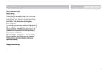
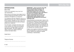
Introduction
INTRODUCTION
DEAR OWNER,
THANK YOU FOR DECIDING TO BUY ONE
OF OUR NEW CARAVANS. WE ARE SURE
YOU WILL ENJOY MANY HAPPY HOURS
IN IT AND WE HOPE THE INFORMATION
AND HINTS IN THIS HANDBOOK WILL
HEIGHTEN YOUR ENJOYMENT.
THE HANDBOOK HAS BEEN DESIGNED
TO GIVE YOU A GENERAL GUIDE TO THE
CARE, USE AND MAINTENANCE OF YOUR
CARAVAN. WHETHER YOU ARE A NEW OR
AN EXPERIENCED CARAVANNER THE
HINTS WILL HELP TO PROTECT YOUR
INVESTMENT.
THE INFORMATION CONTAINED WILL
ANSWER MOST OF YOUR QUERIES, BUT
IF THERE ARE ANY ASPECTS WHICH ARE
NOT COVERED PLEASE CONSULT YOUR
APPOINTED DEALER.
HAPPY CARAVANNING!
Warranty Information
The Towing Code
Safety and Security
Services
Electrical Equipment
Fitted Equipment
Maintenance
CONTENTS
General Data
WARRANTY
INFORMATION
Warranty and guarantee cover ................................................
6 year body shell integrity guarantee......................................
3 year supersure manufacturer’s guarantee ..........................
General terms and conditions .................................................
What to do if you require assistance ......................................
Annual service/inspection record............................................
Annual service/inspection record stamps ..............................
2
2
2
3
5
6
7
Warranty
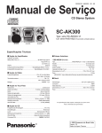
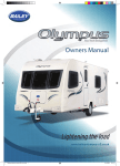
All the illustrations and descriptive matter in
this handbook are intended to give a
general idea of the caravan. Changing
market and supply situations and our policy
of continuous product development may
prevent us from maintaining the exact
specifications detailed in this handbook.
We therefore reserve the right to alter
specifications as materials and conditions
demand.
Dealers are not agents of Swift Group
Limited, the manufacturer of Swift Group
caravans, and have absolutely no authority
to bind the manufacturer by any express or
implied undertaking or representation.
WARRANTY AND GUARANTEE COVER
All Swift Group caravans have a 6 year
body shell integrity guarantee and a 3 year
SuperSure manufacturer's warranty from
the date of purchase (or hire purchase),
which are subject to a chargeable annual
service, inspection and moisture survey
(“Annual Service”) being carried out at an
authorised Swift Group Service Centre.
Original VAT invoices must be retained as
proof of Annual Services being carried out.
In the unusual event that a fault develops
and you need to claim under this Warranty
and Guarantee, your first contact should
normally be made through the dealer from
whom the caravan was purchased.
2
In certain circumstances, arrangements can
be made to have the claim dealt with by a
different authorised Swift Group Service
Centre – see final paragraph below for
details. It is the responsibility of the
Purchaser to deliver the caravan to and
collect the caravan from the Service Centre
for all warranty work.
provided that the caravan has had an Annual
Service, within 90 days before or 60 days after
each anniversary of the original date of
purchase (or hire purchase). The sixth Annual
Service must, however, be carried out before
the expiry of the 72 month period from the
original date of purchase (or hire purchase).
During the warranty period, subject to the
exclusions set out in this section of the
handbook and provided the warranty claim
is authorised by the manufacturer, Swift
Group Limited, the authorised Swift Group
Service Centre will repair (or at the option of
the manufacturer, replace) all defective
parts of the caravan at the expense of the
manufacturer. Swift Group Ltd reserves the
right to examine the caravan prior to
commencement of repairs or replacement
of parts.
Seams and panels requiring repair must be
part of the original construction of the caravan
and must not have been tampered with or
repaired otherwise than by Swift Group Ltd or
an authorised Swift Group Service Centre.
6 YEAR BODY SHELL INTEGRITY
GUARANTEE (“GUARANTEE”)
The Guarantee extends to the
following items:Body leaks and delamination: water ingress
through any permanently sealed seam
joints or delamination of panels and floor,
being part of the original manufacturer’s
construction.
The manufacturer will honour the Guarantee
for 72 months from the date of purchase,
Specific exclusions from the Guarantee:-
Also see general terms and conditions.
3 YEAR SUPERSURE MANUFACTURER'S
WARRANTY (“WARRANTY”)
The manufacturer will honour the Warranty for
36 months from the date of purchase (or hire
purchase), provided that the caravan had an
Annual Service within 90 days before or 60
days after each anniversary of the original date
of purchase (or hire purchase).
The third Annual Service must, however, be
carried out before the expiry of the 36 month
period from the original date of purchase
(or hire purchase).
Warranty
In the first 12 months the Warranty will
cover:-
• Soft furnishings including upholstery,
curtains, pelmets.
Faults arising from a manufacturing defect but
not those which are a result of normal wear
and tear or those which relate to replacement
light bulbs.
• Carpets, lino and floor coverings
including door mats, shower mats.
Also not covered under the first year are faults
resulting from accidental damage or damage
caused by misuse of any component part of
the caravan.
• Work surfaces, tables, and flaps.
• Wallboards, ceiling boards and all other
interior décor finishes.
• Window catches, stays and
associated fittings.
In the years two and three the Warranty
will cover:-
• Blinds and flyscreens including door,
Heki and other rooflights.
1. All original components of the caravan
including permanently fitted equipment
forming part of the manufacturer's
original specification.
• All hinges, catches, knobs, stays and
handles (interior and exterior).
2. Water ingress and body delamination.
Specific exclusions from the Warranty
during years two and three:• Glass including heat shields,
sink lids, mirrors.
• Paintwork including all exterior paint,
heat shields, heater cases and all other
painted surfaces.
• Decals, mirror transfers, resin badges.
• GRP/ABS A frame covers, wheel spats
and skirts.
• Replacement of bulbs, fluorescent tubes,
fuses and electrical connections
including 12n, 12s and 13 pin plugs, high
level brake lights and bulb contacts.
• Audio equipment including radios,
televisions, speakers, aerials and
associated parts.
• Corner steadies.
• Fair wear and tear, accidental damage or
any damage caused by the misuse of any
component fitted by the manufacturer.
• Microwave.
Specific exclusions from the Warranty
during third year:• Truma Heater.
• Glen Dimplex cooking appliances.
• Routine maintenance items which are
part of the Annual Service including
brake shoes, one shot nuts, lubricants,
AKS pads, rubber gas hose, the
cleaning of the heater and fridge flues,
the replacement of gas jets, the
resealing and/or replacement of shower
room sealant, and the adjustment and
lubrication of locks.
GENERAL TERMS AND CONDITIONS
Provided that the caravan is used only for
its ordinary and intended purpose and has
not been subject to any treatment or
conditions which could not be reasonably
foreseen by Swift Group Ltd, the Warranty
and Guarantee will be honoured subject to
the following General Terms and Conditions
which apply to all three years of the
Warranty period and all six years of the
Guarantee period. The caravan is not
covered for:• The failure of a component for reasons
of fair wear and tear.
• Damage resulting from accidents.
• Damage resulting from freezing,
over-heating or fire.
• Misuse or abuse of the caravan or
of any component.
• Tyres, wheels and jockey wheels
• Cosmetic finishes to kitchen sinks,
cooker tops, vanity units, shower trays.
3
Warranty
• Normal deterioration, corrosion, intrusion of
foreign or harmful bodies, lack of servicing
or negligence of any person other than the
Swift Group Limited which causes
stoppage of or impairment to the function
of any component of the caravan.
• Replacement of parts which have reached
the end of their effective working life
because of age and/or usage.
• Cleaning or adjustment of any assemblies.
• Towing other than by private cars or 4x4
vehicles used in place of cars.
• The cost of transporting, towing or
moving the caravan by any means
(or consequential costs relating to
transportation), to or from the place
of repair, which is the responsibility of
the owner.
The Warranty and the Guarantee will be
invalidated if the caravan has been neglected,
misused, modified, used for hire or reward or
any commercial use, or has been used in
competitive events. The caravan will be
deemed to have been neglected if it has not
had an Annual Service or has otherwise not
been serviced and maintained as required by
this handbook.
4
The Warranty and the Guarantee only apply
to caravans purchased and used within the
UK, and for continuous journeys abroad of
no longer than 90 days per journey.
If any repairs are identified as being
necessary during an Annual Service, the
caravan must be made available to an
authorised Swift Group Service Centre
within 6 weeks for the work to be carried
out. All new caravans must be registered
with the Swift Group Ltd within 6 weeks of
purchase as new.
The benefit of this Warranty and Guarantee
may be transferred to a new owner if the
caravan is sold, provided that the caravan
has been serviced by an authorised Swift
Group Service Centre in accordance with
the requirements of this handbook, and
details of the change of ownership have
been supplied to Swift Group Ltd using the
change of ownership form set out in this
handbook. Failure to notify Swift Group Ltd
of a change of ownership within 30 days of
such a change will invalidate the Warranty
and Guarantee.
You have legal rights under UK law
governing the sale of consumer goods.
This Warranty and Guarantee does not
affect your legal rights.
The name and address of the warranty and
Guarantee provider is:Swift Group Limited,
Dunswell Road,
Cottingham,
East Yorkshire,
HU16 4JX.
To make a claim under this Warranty or
Guarantee, contact the Swift Group Service
Centre which supplied your caravan.
Alternatively, details of your nearest
authorised Swift Group Service Centre can
be obtained by contacting the Swift Group
Customer Care Department on 01482
875740 or enquiring on our web site:
www.swiftleisure.co.uk
Assistance
WHAT TO DO IF YOU REQUIRE ASSISTANCE
Congratulations on purchasing your new caravan. We are confident that you will enjoy
many happy holidays. However, should you have an enquiry or require assistance with a
problem, we hope that this guide will be of assistance to you.
If you have a problem, or enquiry with regards to your new caravan, please follow
these steps:
1. Check the Owners Handbook, paying particular attention to the fault finding advice at
the back of the book.
2. Contact your supplying dealer for assistance.
If you need to contact the Swift Group, please be aware of the following:
1. When contacting Swift Supercare, please quote your name, postcode and serial number
of your caravan.
2. In most instances, the Customer Care Team will involve your dealer in resolving the issue
you are experiencing.
3. If you are contacting the company by email, letter or fax, the Customer Care Team will
respond to you within five working days from the date of receiving the correspondence.
4. If you are calling the Customer Care Team, please avoid where possible, Mondays and
lunch times.
5. Please be aware that the Swift Group cannot send parts direct from the factory. In all
cases, without exception, your dealer must place the order for you.
5
Assistance
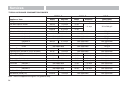
TOURING CARAVANS - ANNUAL SERVICE/INSPECTION RECORD
In order to comply with the warranty, you must have your caravan inspected and serviced
by an authorised Swift Group Service Centre at least once per year.
It is important that the Owner’s Handbook is stamped on the appropriate page by the
authorised Swift Group Service Centre. Failure to do this will invalidate the warranty and the
transfer of the warranty on the change of ownership.
The inspection should take approximately two to four hours and will cover the areas dealt
with in the annual service check list. Any areas requiring service and/or maintenance will be
highlighted by your dealer and we recommend that you authorise any necessary work to be
carried out.
NB. It is essential, to validate the warranty, that an annual inspection be carried out by an
authorised Swift Group Service Centre covering the items listed.
1.
2.
3.
4.
5.
6.
7.
8.
9.
10.
11.
12.
13.
14.
15.
6
Damp and lamination test.
Coupling head and breakaway cable.
Jockey wheel.
Chassis and chassis to body security.
Corner steadies.
Folding step (if fitted).
Tyres and tyre pressures.
Torque wheel nuts.
Brake rods and linkages.
Hub bearings, brakes and brake shoes.
Handbrake operation and
performance.
Suspension and shock absorbers
(if fitted).
12N and 12S 7-pin or 13 pin plugs
and cables.
Road lights, wiring and reflectors.
Internal lights and 12V DC system.
16. Water heater - gas and 230V AC
(if fitted).
17. Hob, grill and oven (if fitted).
18. Refrigerator 230V AC, 12V DC
and gas.
19. Gas system.
20. Water pump, taps and water system.
21. Mains 230V AC system.
22. Windows and fittings.
23. Smoke alarm and battery.
24. Roof lights.
25. Furniture hinges/stays etc.
26. Exterior locks and hinges.
27. Grab handle security.
28. All internal vents.
29. Oil seals.
30. Blinds and fly screens (if fitted).
Service/Inspection
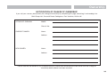
ANNUAL SERVICE/INSPECTION RECORD
CARAVAN MODEL
YEAR
CHASSIS NUMBER
1st SERVICE
2nd SERVICE
DATE:
DATE:
DEALER’S STAMP
DEALER’S STAMP
We certify that an annual service has been carried out in
accordance with the handbook.
We certify that an annual service has been carried out in
accordance with the handbook.
3rd SERVICE
4th SERVICE
DATE:
DATE:
DEALER’S STAMP
DEALER’S STAMP
We certify that an annual service has been carried out in
accordance with the handbook.
We certify that an annual service has been carried out in
accordance with the handbook.
7
5th SERVICE
6th SERVICE
DATE:
DATE:
DEALER’S STAMP
DEALER’S STAMP
We certify that an annual service has been carried out in
accordance with the handbook.
We certify that an annual service has been carried out in
accordance with the handbook.
7th SERVICE
8th SERVICE
DATE:
DATE:
DEALER’S STAMP
DEALER’S STAMP
We certify that an annual service has been carried out in
accordance with the handbook.
9th SERVICE
10th SERVICE
DATE:
DATE:
DEALER’S STAMP
DEALER’S STAMP
We certify that an annual service has been carried out in
accordance with the handbook.
8
We certify that an annual service has been carried out in
accordance with the handbook.
We certify that an annual service has been carried out in
accordance with the handbook.
THE
TOWING
CODE
The Caravan Towing Code .................................................... 12
Scope of the Code ............................................................... 12
Caravan Terms ........................................................................ 12
Weights ................................................................................ 12
Towing Vehicle Terms ............................................................ 13
Weights ................................................................................ 13
Measurement of Noseweight ................................................ 15
Type of Driving Licence Held ..................................................15
Glossary & Checklist .............................................................. 15
Preparing for the Road .......................................................... 17
Checklist .............................................................................. 18
Loading & Distribution ......................................................... 18
Stability ................................................................................ 19
Tyres ..................................................................................... 20
Pre-tow Checklist ................................................................. 22
Moving Off ............................................................................... 28
Reversing ................................................................................ 29
Speed Limits ........................................................................... 29
Caravan Handling ................................................................... 29
Motorway Driving ................................................................... 29
Changing a Wheel .................................................................. 30
Jacking Points ........................................................................ 31
Stopping on a Hill ................................................................... 31
Arrival on Site ......................................................................... 31
The Towing Code
THE CARAVAN TOWING CODE
This Code of Practice contains
recommendations jointly reviewed and
agreed by the following organisations:
The
The
The
The
The
National Caravan Council
Caravan Club
Camping and Caravanning Club
Caravan Writers Guild
Department for Transport
Scope of the Code
The Code applies to all trailer caravans of
maximum laden weight not exceeding
3500 kg (7,700 lbs), overall width not
exceeding 2.3m (7ft 6in approximately) and
overall length not exceeding 7m (23ft
approximately), excluding the drawbar and
coupling.
This is legally the maximum size of trailer
that can be towed by a motor vehicle with a
maximum gross weight of less than 3500 kg.
CARAVAN TERMS
Mass in Running Order:
The mass of the caravan as stated by the
caravan manufacturer, as new with standard
fixtures and fittings.
Note: Because of differences in the weight
of materials supplied for the construction of
caravans, a tolerance has been allowed for
in the Mass in Running Order weight.
12
Maximum User Payload:
The maximum allowable weight to be put
into the caravan whilst it is being towed. This
is made up of 3 sections:
Personal effects, optional equipment and
essential habitation equipment.
The user payload is the difference between
the Maximum Technically Permissible Laden
Mass and the Mass in Running Order.
Essential Habitation Equipment:
Those items and fluids required for safe and
proper functioning of the equipment for
habitation as defined by manufacturer of the
caravan.
Personal Effects:
Those items which a user can choose to
carry in a caravan and which are not
included as Essential Habitation Equipment
or Optional equipment.
Optional Equipment:
Items made available by the manufacturer
over and above the standard specification of
the caravan.
Maximum Technically Permissible Laden
Mass:
The maximum weight for which the caravan
is designed for normal use when being
towed on a road, laden. This mass takes into
account specific operating conditions
including factors such as the strength of
materials, loading capacity of tyres etc.
WARNING: Under no circumstances
should the maximum technically
permissible laden mass of this caravan
be exceeded.
Upgrading of maximum technically
permissible laden mass:
The standard/declared MTPLM quoted in the
specification handbook and on new caravan
weightplates maybe of lower value than the
maximum possible. If extra user payload is
required, an upgrade maybe available (model
dependant), this must be requested via your
dealer.
If required you will be issued with the
following:
(i) New weightplate giving upgrade
weight detail
(ii) New NCC Certificate (declaring the
upgraded MTPLM
(iii) Manufacturers letter confirming
the upgrade for that Vehicle
Identification Number
Note: Tyre pressures may increase
when upgrading
Nose weight:
That part of the static mass of the caravan
supported by the towing device on the rear
of the towing vehicle.
The Towing Code
Notes:
(i) When measuring the noseweight it is
important that the caravan is fully
loaded. Do not place extra items
indiscriminately into the caravan after
this adjustment has been made.
(ii) The caravan is intended to be towed
slightly nose heavy. The nose weight
can be adjusted by distribution of the
load within the caravan. The nose
weight should be approximately 7% of
the actual laden weight (but not greater
than the hitch capacity) and at the same
time suit the towing vehicle. See section
on Measurement of Nose Weight.
(iii) It is not recommended that you tow with
just a battery, spare wheel and gas
bottles as this may exceed the the
permitted nose weight. Additional
payload must be placed behind the axle
to compensate for this.
TOWING VEHICLE TERMS
Kerb weight (Mass of Vehicle in Running
Order):
The weight of the towing vehicle as defined
by the vehicle manufacturer. This is normally
with a full tank of fuel, with an adequate
supply of liquids incidental to the vehicles
propulsion, without driver or passengers,
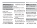
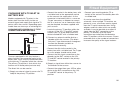
YES
NO
85%
MAYBE
EQUAL
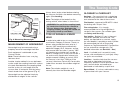
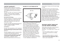
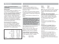
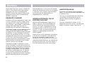
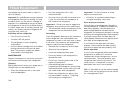
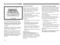
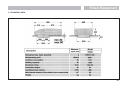
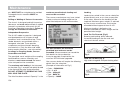
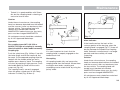
Fig. A Car/Caravan Weight Ratios
without any load except loose tools and
equipment with which the vehicle is normally
provided and without any towing bracket.
Power to weight ratio:
No hard and fast rules can be stated but,
here is a general guide.
Caravan to Towing Vehicle Weight Ratio:
The towing vehicle to caravan weight ratio
can be determined by calculation and is
equal to:
(a) Conventional petrol engines with a
capacity up to approximately 1500 cc
should be adequate for towing a
caravan weighing around 85% of the
kerb weight of the towing vehicle.
actual laden weight of caravan
Kerb weight of towing vehicle
x 100%
THE LAW REQUIRES THAT CARAVANS &
THEIR TOWING VEHICLES & THE LOADS
THEY CARRY MUST BE IN SUCH A
CONDITION THAT NO DANGER OR
NUISANCE IS CAUSED.
(b) Above 1500 cc such engines should
manage a caravan weighing up to 100%
of the kerb weight of the towing vehicle
and still give adequate performance.
(Regulation 100 of the Road and Vehicles
[Construction and Use] Regulations 1986).
13
The Towing Code
Note: The towing vehicle manufacturer’s limit
is, in some cases, less than the kerb weight.
Vehicles with automatic transmission may
need an oil cooler fitting or the SAE rating of
the gearbox oil increasing when towing. The
advice of the vehicle manufacturer should be
sought.
Mass in Running Order:
Caravanners can use a public weighbridge to
establish the mass in running order.
Note: Weighbridges have varying weight
tolerance levels.
Maximum Permissible Towing Mass:
The weight defined by the vehicle
manufacturer as being the maximum that
the vehicle is designed to tow.
Train Weight (Combination Weight):
The maximum combined weight of the
towing vehicle and trailer combination as
specified by the towing vehicle manufacturer.
14
The Towing Code
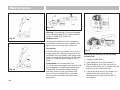
Always lower jockey wheel before entering
the caravan and then raise before measuring
again. (See Loading).
Note: The height of the towball on the
towing vehicle, when laden, is also critical.
430mm
+ 35mm
-
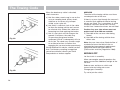
WARNING: Do not lift the coupling head
by hand when hitching the caravan to
the car. Always raise and lower the
coupling head by winding the handle on
the jockey wheel up and down.
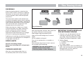
TYPE OF DRIVING LICENCE
HELD
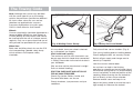
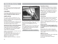
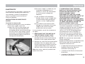
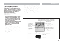
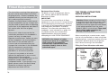
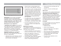
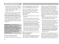
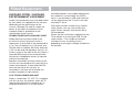
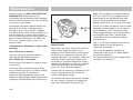
Fig. A Measuring Noseweight
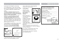
MEASUREMENT OF NOSEWEIGHT
Noseweight may be measured using a
propriety brand of noseweight indicator.
Such equipment is obtainable at your
Caravan Dealer.
Note: These indicators have a varying
tolerance level.
Another simple method is to use bathroom
scales under the coupling head with a piece
of wood, fitted between the coupling head
and the scales, of such length that the
caravan floor is horizontal with the jockey
wheel raised clear of the ground. (Fig. A)
In order to be able to tow a caravan a driver
must hold a Category B licence. Those car
drivers who passed their tests prior to 1
January 1997 would have automatically
obtained Category B+E. However, anyone
who passed their test after 1 january 1997
will need to take a further test in order to
obtain a Category B+E if they wish to tow a
car and caravan combination whose train
weight exceeds 3,500kg, or up to 4,250 if
the caravan is less than 750kg or if the
caravan’s Maximum Technically Permissible
Laden Mass exceeds the unladen weight of
the car.
Note: The unladen weight of a car is
normally less than the kerbside weight.
GLOSSARY & CHECKLIST
Awnings - Can consist of just a simple top
sheet but may extend to a five sided frame
tent attached to the side of the caravan.
Fire blanket - approved to BS 6575 is ideal
for dealing with ‘fat pan’ fires.
Fire extinguisher - It is strongly
recommended that a fire extinguisher is
carried in the caravan. (For suitable types
see Safety and Security).
Gas bottles - Bottled L.P. gas is the most
convenient portable source of fuel. Two
bottles are required for a constant supply.
An initial deposit is payable on each cylinder.
We recommend the use of 5kg or 6kg
Propane or 7kg Butane bottles. One position
for use and one for storage only. (For
detailed information see Services - Gas).
Jack - A suitable jack is essential (screw,
scissor, side mounted or air jack type). Many
car jacks are unsuitable.
Levellers - Levellers help level the caravan
from side to side before unhitching.
Proprietary products can be purchased from
your caravan dealer and need to be
positioned as indicated by a spirit level.
Spare Wheel - It is always advisable to carry
a spare wheel with your caravan.
Noseweight can be adjusted simply by
distribution of weights in the caravan.
15
The Towing Code
Spirit Level -A spirit level is extremely useful
when siting the caravan.
types are available including jerry cans,
folding cans and wheeled containers.
Stabiliser -Stabilisers help to dampen the
side to side movement of the caravan. One
end fits to the car’s towing bracket and the
other end to the caravan. (See Stability)
12N & 12S Sockets - Two sockets
designated 12N and 12S are fitted to your
car to accept corresponding plugs from the
caravan. These are necessary to energise
the road lights and caravan auxiliary circuits
respectively.
Torque Wrench - A torque wrench is the
only way that the exact recommended
torque can be achieved for wheel nuts and
bolts. (See Preparing for the Road).
Towing Bracket - Never use cheap
alternatives, obtain one manufactured by a
reputable company complying with the
relevant standards.
Any light passenger vehicle registered in the
UK on or after August 1st 1998 (S registered
plate) will require a type approved towbar
and towball (to 94/20/EC). Failure to fit a
homologated towbar and towball could
result in a prosecution and invalidation of
your insurance cover. Always check with
your car manufacturer or towbar
manufacturer if in doubt.
Wooden Blocks - Wooden blocks typically
25cm. square and 2cm. thick are ideal for
placing under corner steadies and jockey
wheel when the ground is uneven or soft.
Water Containers - Two containers are
required, one to carry fresh water to the
caravan and one for waste water, which
needs to be disposed of properly. Several
16
13 Pin Sockets (alternative to 12N & 12S) One socket fitted to the car this energise the
Road lights and caravan auxiliary circuits.
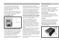
12 Volt Battery - A deep cycling, heavy duty
rechargeable leisure type battery should be
purchased to provide back-up power for
lights and other electrical appliances. (See
Battery). The securing arrangements for the
battery compartment require a leisure battery
complying with EN 60095-2 in particular
those with ledges for fastening to the lower
edge of the long sides and having a
maximum height of 190mm and width of
175mm.
WARNING: Your caravan dealer should
be consulted if additional equipment is
to be fitted as strong points may or may
not be provided in the design.
Note: Fitting additional equipment will
reduce the caravan allowable payload.
The Towing Code
Useful memory aid for other items.
Car
Distilled water
External mirrors
Fan belt
Fire extinguisher
Jack
Jump leads
Petrol can
Socket set
Spare bulbs
Spare keys
Spare wheel
Tool kit
Towball cover
Tow rope
Tyre pressure gauge
Warning triangle
Tyre Pump
Caravan
Awning pegs and poles
Awning ground sheet
Battery 12 volt charger
Bucket
Corner steady brace
Corner steady pads
Coupling lock
Door mat
Fire blanket
Fire extinguisher
Fresh water container
Gas cylinder
Gas regulator
Jack
Levelling boards
Mallet
Site/caravan mains lead
Spare bulbs
(Mandatory in E.C.)
Spare 12v fuses
Spare gas hose
Spare wheel
Spirit level
Toilet fluid
Waste water container
Wheel brace
Personal
After sun cream
First Aid Kit
Flannels
Hairbrush and comb
Make up. etc.
Raincoats
Toothbrush
Toothpaste
Scissors
Shampoo
Shaving kit
Shoe cleaning kit
Soap
Sun tan oil
Wellington boots
Domestic
Adhesive tape
Air freshener
Aluminium foil
Ashtrays
Bin liners
Binoculars
Bottle opener
Breadboard
Breadbin
Brush and dustpan
Butter dish
Camera and films
Carving knife
Cassette recorder
Chairs
Clock
Clothes brush
Clothes line
Coat hangers
Coffee percolator
Coolbox
Colander
Crockery
Cruet
Corkscrew
Cutlery
Dish cloth and brush
Dusters and polish
Disposable cloths
Egg cups
Electrical extension lead
Floor cloth
Fly spray
Food
Food mixer
Frying pan
Glasses
Grill pan
Jugs
Kettle
Kitchen roll
Kitchen tools
Litter bin
Matches
Measuring jug
Milk jug
Mixing bowl
Needles and thread
Oven gloves
Pegs
Piezo Gas lighter
Potato peeler
Pressure cooker
Radio
Rubbish bin
Salad shaker
Saucepans
Scissors
Sieve
Sugar bowl
Shopping bags
Sleeping bags
Tea pot
Tea strainer
Tea towels
Table cloths
Table mats
Television
Tin opener
Tissues
Toilet paper
Torch
Towels
Toys & Games
Vacuum cleaner
Washing up bowl
Documents
Bail Bonds
(some Euro countries)
Bank and credit cards
Caravan Certificate
Cheque book
CRIS document
Driving licence
Green Card Insurance
(some Euro countries)
Maps and guides
Money
MOT Certificate
Vehicle Registration
Documents
17
The Towing Code
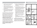
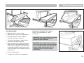
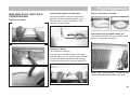
PREPARING FOR THE ROAD
PRE-LOAD CHECKLIST
Caution: Never enter the caravan without
first lowering the four corner steadies with
the brace provided.
(a)
(b)
(d)
BEFORE LOADING CHECK:
-
loose articles are stowed securely. Do not
stow tins, bottles or heavy items in
overhead lockers prior to towing.
(c)
-
all lockers and cupboard doors are
closed and secured.
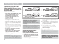
Fig. A Loading your caravan
-
all bunks are secure.
-
all rooflights are closed and secured.
-
main table is stored in its transit position.
-
fridge is on 12V operation and door lock
is set.
-
all windows are fully closed and latched.
Never tow with windows on night setting.
Leave all curtains and blinds open to aid
rear visibility.
-
gas cylinders are correctly positioned,
secured and turned off.
-
battery is secure and mains connecting
cable is disconnected and stowed.
-
12V distribution panel selector switch is
set to the van position.
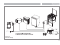
WARNING: The fridge will only operate
in transit when the 12V distribution panel
selector switch is in the 'VAN' position.
18
WARNING: Turn off gas appliances
except those heating appliances
designed to function while the vehicle is
in motion.
WARNING: Do not travel with televisions
or microwaves in overhead lockers
unless the appliance was supplied fitted
to your caravan by the manufacturer.
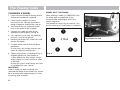
caravan wheel carries approximately the
same weight.
3. Do not load items at the extreme front or
rear since this can lead to instability due
to the ‘pendulum effect’.
4. Load remainder to give a suitable
noseweight at the towing coupling.
Check noseweight.
Note: Do not overload car boot.
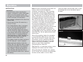
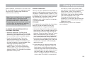
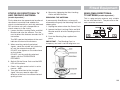
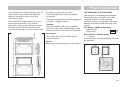
LOADING AND DISTRIBUTION OF
WEIGHT IN THE CARAVAN
Do not exceed recommended maximum
loading for your caravan.
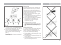
1. Load heavy items low down near the
floor and mainly over or just in front of
the axle(s) (Fig. A).
2. Load evenly right to left so that each
Note: Please take care to ensure that you
have allowed for the masses of all items
you intend to carry in the caravan.
WARNING: All heavy and/or voluminous
items (e.g. TV, radio etc) must be stored
securely before travelling.
The Towing Code
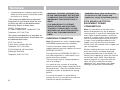
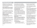
Sensible Loading:
How to apportion it
LIGHT
Fig. A ITEMS
MEDIUM
ITEMS
HEAVY
ITEMS
Towing vehicle’s rear suspension
It is important that the towing vehicle’s rear
suspension is not deflected excessively by
the noseweight on the tow ball. If it is
excessive the steering and stability will be
affected. (Fig. B)
The greater the towing vehicle’s tail overhang
(the distance between the rear axle and the
tow ball), the greater the effect the
noseweight will have on the towing vehicle’s
rear suspension.
After trying out the caravan it may be found
that a stiffening of the rear suspension is
necessary - but note that this may give the
towing vehicle a firmer ride when not towing.
Fig. B Illustration of excessive deflection of vehicle’s rear suspension
There are a number of suspension aids
available and advice should be sought on
which to use and how to fit. It is important to
ensure that the caravan is towed either level
or slightly nose down.
If you have any doubts about the suitability
of your towbar for towing a caravan consult
the towing bracket manufacturer.
DO NOT exceed the:
• Gross Vehicle Mass (G.V.M. on car plate).
• Maximum Technically Permissible Laden
Mass (M.T.P.L.M.) on the caravan.
• Gross Vehicle Combination Mass
(Train Weight) (G.V.C.M. on car plate).
• Maximum Permissible Towing Mass.
• Vertical Static Load on the caravan
coupling.
• Maximum Vertical Load on the car towball
as specified by towing vehicle
manufacturer.
STABILITY
All our models are of a well balanced design
and should be exceptionally good towers.
Most models have an AL-KO stabiliser fitted
as standard. The common causes of poor
stability include:
(a) Worn springs or loose spring fixings on
the towing vehicle.
(b) Towing vehicle springs too soft.
(c) Insufficient noseweight.
(d) Nose of caravan is towing too high.
19
The Towing Code
Galvanised steel chassis
Drilling of the galvanised steel chassis will
invalidate the warranty and must not
be done.
Towball
The AL-KO stabiliser is designed to be used
with a swan neck, fixed or detachable
towball. If you use a 'bolt on type' towball
you may need to replace your towball with a
special extended neck towball.
If you have a bolt on type towball you should
ask your dealer to check clearance around
the towball to allow for the stabiliser
to articulate.
The AL-KO extended neck towball (available
from your dealer) is approved and marked
with the approval number EC94/20. Failure to
provide enough clearance around the towball
may invalidate your stabiliser warranty.
AK160 coupling head
If your caravan is fitted with an AK160
coupling head the Towball must be
lightly greased.
Stabiliser friction pads
The AL-KO stabiliser uses 'friction pads'
inside the coupling head to clamp the
towball. These pads must be kept free from
grease and contamination from the towball.
The friction pads should last approximately
50,000km (30,000 miles) under normal use, if
correctly maintained.
20
Suitable towing vehicles
The caravan is manufactured for towing
behind normal road cars and is not suitable
for towing behind commercial vehicles. It is
strongly recommended that whenever a
caravan is to be towed over rough terrain,
e.g. a farmer’s field or track, great care
should be taken to ensure that no undue
stress is placed upon the caravan via the
hitch mounting, i.e. reduce speed. If in
doubt, please consult the chassis manufacturer and the towing vehicle manufacturer
who will advise. Touring caravans based on
standard AL-KO chassis can be towed by
four wheel drive off road leisure vehicles
providing the unit is used to tow in a like
manner to a conventional road-going car and
driven in the same considered manner.
Towbar manufacturers should be consulted
before towing an uncompensated twin
axle caravan.
Snaking
This is a term used to denote an unstable
car and caravan combination where the
caravan ‘weaves’ from side to side often
causing a similar swaying movement in the
car itself.
Causes:
i) Unsuitable or unbalanced outfit.
ii) Incorrect loading or weight distribution.
iii) Excessive speed especially downhill.
iv) Side winds.
v) Overtaking.
vi) Being overtaken by a large fast moving
vehicle.
vii) Erratic driving.
viii) Insufficient tyre pressures.
ix) Mixing radial and cross ply tyres.
Cures:
Cases of persistent snaking can be
alleviated by the use of a stabiliser.
On the road
If you do find your outfit snaking, try to keep
the steering wheel in a central position as
far as possible, decelerate and avoid
braking if possible.
Types of tyres fitted
The original tyres fitted by the manufacturer
are suitable for towing at maximum speed
of up to 81 mph (130 kph).
TYRES
Caravan manufacturers choose the type,
size, profile, load carrying capacities and
speed ratings to match the design masses of
there vehicles, adjusting the tyre pressures to
suit. Only change the type of tyres on your
caravan on expert advice from the caravan
manufacturer, or tyre manufacturer.
TYRE MAINTENANCE
Tread depth
Pay special attention to the amount of tread
remaining on your tyres, and measure them
regularly. Always replace tyres before they
reach the minimum legal limit of 1.6mm.
The Towing Code
Periodically tyres should be rotated to equalise
wear in the same manner as car tyres.
Pressures
The caravan manufacturers plate (fixed
adjacent to exterior door) and Technical
handbook contains information about
caravan loading and the required
adjustments to tyre pressures, which should
be followed for safety. Tyre pressures should
always be checked and corrected prior to
each journey. It is vital that tyre pressures are
maintained at the levels recommended by the
manufacturer to ensure maximum tyre life,
safety and handling characteristics.
Over or under-inflating tyre is likely to
seriously impair their performance and may
prejudice the safe use of the vehicle.
Over-inflation increases overall tyre diameter,
decreases the amount of tread in contact
with the road, decreases sidewall flexibility
and affects road-adhesion.
Under-inflation decreases overall tyre
diameter, increases sidewall flexing,
generates higher tyre operating temperatures
and difficult vehicle handling characteristics.
Running an under-inflated tyre may cause
premature tyre failure. Both over and underinflation adversely affect tyre life.
Treads
Keep tyre treads clean of stones and other
foreign bodies, and check regularly for
damage to the tread and sidewalls. It is vitally
important that any damage is checked out by
a tyre expert and any necessary repairs or
replacements are carried out immediately.
Tyre valves
Check tyre valves carefully. Ensure the caps
are in place free from dirt/ debris and that
there is no evidence of cracking or damage
to the valve stem
Tyre Aging
Rubber compounds used in tyres contain
chemicals that help to slow down the natural
aging process of untreated rubber. However,
tyres do deteriorate with age, which
increases the risk of tyre failure, and there are
many ways in which this can be spotted:
• Cracking/crazing on the side wall of the
tyre, caused by its flexing
• Distortion of tyre tread
• Deformation of the carcass of the tyre
There will also be a deterioration of the ride
quality caused by vibrations through the tyre.
This may signify the tyres performance has
been affected by age and should be
investigated as soon as possible
Tyres that display signs of aging should be
removed and not put to further use.
The effects of aging can be brought about
prematurely in several conditions. Tyres fitted
as spare wheels may age prematurely. If tyres
on caravans are not in regular use they
should be inspected before every journey,
several cleaning products may also harm the
chemicals in the rubber. However, the age of
a tyre will affect its safety and increase the
risk of failure, and you should inspect tyres
for the signs of aging regularly.
THE TYRE LAW
Tyre pressures
Tyre pressures should be maintained at or
within a very close tolerance of the
recommended pressures.
Tyre tread depth and damage
When tyres become worn or damaged they
must be replaced. There must by law, be at
least 1.6mm of tread depth across the centre
3/4 of the width of the tread throughout the
entire circumference of the tyre. There must
be no damage to the tyre body - sidewalls or
tread, no bulges or cuts.
Tyre types
IT IS RECOMMENDED THAT TYRES ARE
REPLACED AFTER 5 YEARS SERVICE
INCLUDING THE SPARE.
It is illegal to mix tyres of a different
construction on the same axle.
21
The Towing Code
Note: Although the caravan may be fitted
with the same type of tyre as the towing
vehicle, the pressures specified are different.
All charts show values for cars and are
therefore not applicable for caravans.
Pressures displayed on tyre walls apply
ONLY in North America and Canada.
Wheels
Caravan wheel bolts should be tightened to a
torque of 88Nm (65lb/ft) on steel wheels or
115Nm (85lb/ft) on alloy wheels and should
be checked with the use of a torque wrench
regularly. Only use a spare wheel and tyre of
the type and size provided with you caravan.
Wheel rims
Both steel and Alloy wheel rims are the 5.5J
size incorporating a double safety hump
which conforms to European safety
standards.
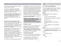
Fig. A Winding Corner Steady
If in any doubt, have your wheels checked
by a competent tyre supplier.
Hitch head load capacity
The maximum vertical static load which can
be put upon the hitch head when connected
is 100kg. Please refer to the technical data in
your handbook.
(But see also vehicle manufacturer’s weight
limits on towball loading.)
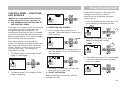
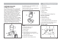
PRE-TOW CHECKLIST AND HITCH-UP
FOR AK 3004 STABILISER
Check Gas Locker, Battery Locker and
Cassette Toilet doors are secure.
Check wheelnuts, tyre pressures and tyre
conditions.
22
Fig. B Safety Catch and Handle
Fully raise all four corner steadies. (Fig. A).
Pick up any levelling pads or levelling boards.
Check rooflights/vents are securely closed.
Switch off gas supply and change over to
electricity if required.
Lock the caravan exterior door.
An assistant can help in the hitching
operation by standing on the left hand side of
the drawbar (facing rear of car) and extending
an arm horizontally to indicate position of the
coupling. When reversing aim the towball of
the car directly at the caravan drawbar.
Remove towball cover and keep in car.
Adjust the jockey wheel to ensure the cup is
high enough to slide over the towball.
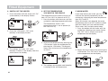
The Towing Code
Fig. A Handbrake
Release caravan handbrake.
Position cup over the ungreased towball,
release and lift forward the large red
stabiliser handle (Fig. B) lift forward the
exposed smaller black handle (Fig. B) until it
clicks up.
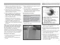
The hitch head is fitted with a visual indicator
to show whether or not it is properly
connected to the towball. A green band will
show immediately below the red indicator
button on the hitch head when a proper
connection has been made. (See Fig. D)
WARNING: If the green band is showing
when the hitch head is not connected
to the towball there is a fault - contact
your Dealer.
Fig. B Checking Secure Attachment
Fig. C Connections - 7 pin Plug
Adjust jockey wheel to lower cup on to the
ball. A click indicates it is fully engaged. Ensure
black handle has returned to its free position.
Secure caravan handbrake. (Fig. A)
Connect breakaway cable as described on
page 27.
Ensure that the jockey wheel is fully wound
up and properly located in the slots, then
release the clamp handle, lift the whole unit
as high as possible and retighten the clamp
handle.
Note: Ensure jockey wheel locates in recess
provided. Carelessness could result in
damage to the A frame cover.
Fig. D Hitch Head Visual Indicator
23
The Towing Code
Take hold of the caravan under the rubber
gaiter behind the coupling and lift to
ascertain whether the caravan is properly
attached. (Figs. B & D.)
Ensure the hitch is secured by checking the
visual indicator (see page 23).
Connect 7 pin plugs to car sockets ensuring
there is enough loose cable for cornering,
(Fig. C) ensuring they wont drag on the
ground.
Check all car and caravan roadlights are
working. Check round the caravan for
anything left behind.
Release caravan handbrake, adjust all
mirrors from driving seat and proceed.
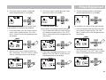
PRE-TOW CHECKLIST AND HITCH-UP
FOR AK 160 COUPLING HEAD
Check Gas Locker, Battery Locker (if fitted)
and Cassette Toilet (if fitted) door/s are
secure.
Lock the caravan exterior door.
An assistant can help in the hitching
operation by standing on the left hand side
of the drawbar (facing rear of car) and
extending an arm horizontally to indicate
position of the coupling. When reversing aim
the towball of the car directly at the caravan
drawbar. Remove towball cover and keep in
car.
Adjust the jockey wheel to ensure the cup is
high enough to slide over the towball.
Release caravan handbrake.
Position cup over greased towball, release
safety catch and lift handle (Fig. B). The
hitch head is fitted with a visual indicator to
show whether or not it is properly connected
to the towball. A green band will show
immediately below the red indicator button
on the hitch head when a proper connection
has been made. (See Fig. D, Page 23)
Fig. B Safety Catch and Handle
WARNING: Serious damage will occur
unless the locking button is depressed
first and the handle lifted forward before
the caravan is lowered manually. This
prevents the noseweight being
transmitted through the locking button.
Check wheelnuts, tyre pressures and tyre
conditions.
Fully raise all four corner steadies. (Fig. A,
Page 22).
Pick up any levelling pads or levelling boards.
Check rooflights/vents are securely closed.
Switch off gas supply and change over to
electricity if required.
24
WARNING: If the green band is showing
when the hitch head is not connected
to the towball there is a fault - contact
your Dealer.
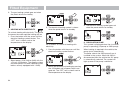
The Towing Code
Fig. A Handbrake
Adjust jockey wheel to lower cup on to the
ball. A click indicates it is fully engaged. Ensure
locking button has returned to its free position.
Secure caravan handbrake. (Fig. A)
Connect breakaway cable (emergency
braking device) in the form of a noose to
suitable anchorage point on towbar. DO NOT
attach to towball. (See page 27)
Ensure that the jockey wheel is fully wound
up and properly located in the slots, then
release the clamp handle, lift the whole unit
as high as possible and retighten the clamp
handle.
Note: Ensure jockey wheel locates in recess
provided. Carelessness could result in
damage to the A frame cover.
Fig. B Checking Secure Attachment
Fig. D Hitch Head Visual Indicator
Take hold of the caravan under the rubber
gaiter behind the coupling and lift to
ascertain whether the caravan is properly
attached. (Figs. B & D.)
Lock hitch if possible (see Safety and
Security, page 36).
Connect 7 pin plugs to car sockets ensuring
there is enough loose cable for cornering.
(Fig. C, Page 23)
Check all car and caravan roadlights are
working. Check round the caravan for
anything left behind.
Release caravan handbrake, adjust all
mirrors from driving seat and proceed.
25
The Towing Code
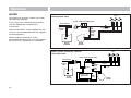
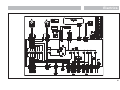
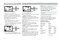
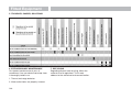
ROAD LIGHTING
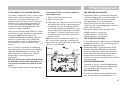
For your information the wiring diagram of the
12N and 12S connectors is shown opposite.
These should be checked regularly and if in
any doubt consult a qualified electrician.
For cars equipped with 12N/12S sockets, an
adaptor may be required when a 13 pin plug
is fitted to the caravan. If so consult your
dealer or qualified electrician.
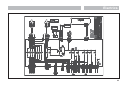
The wiring diagram of the 13 pin connectors
is shown opposite. This should be checked
regularly and if in any doubt a qualified
electrician consulted.
For cars equipped with 13 pin sockets, an
adaptor may be required if the caravan is fitted
with a 12N AND 12S plug fitted to the caravan.
If so consult your dealer or qualified electrician.
12N AND 12S VIEWED FROM REAR OF PLUG
PINS
PINS
STRIPS
12N (BLACK)
TERMINAL
1
2
3
4
5
6
7
COLOUR
YELLOW
BLUE
WHITE
GREEN
BROWN
RED
BLACK
12S (GREY)
12N PLUG
L/H INDICATOR
REAR FOG LAMP
COMMON RETURN (1-7)
R/H INDICATOR
R/H SIDE TAIL & No PLATE LIGHT
STOP LAMP
L/H SIDE TAIL & No PLATE LIGHT
TERMINAL
1
2
3
4
5
6
7
VOLTA/JEAGER
• All road lights must be in working order.
• Lenses and reflectors must be in good
condition
26
COLOUR
YELLOW
BLUE
WHITE
GREEN
BROWN
RED
BLACK
12S PLUG
REVERSING LIGHT
NO ALLOCATION
NEGATIVE PIN 4
CONTINUOUS POWER SUPPLY
NO ALLOCATION
FRIDGE
RETURN FOR FRIDGE
VOLTA/JEAGER & MULTICON FEDER 13 PIN PLUGS (viewed from rear)
The wiring allocations were changed in 1998
and it is important that you check the car to
caravan connections are compatible prior to
coupling up to the car.
WARNING: Always disconnect the
electrical connector between the
towing vehicle and the caravan before
connecting a low voltage supply to the
caravan (mains) and before charging
the battery (EN 1648-1).
TUBES
PIN NO
1
2
3
4
5
6
7
8
9
10
11
12
13
COLOUR
YELLOW
BLUE
WHITE
GREEN
BROWN
RED
BLACK
ORANGE
BROWN/BLUE
BROWN/RED
WHITE/BLACK
WHITE/GREEN
WEST
DESCRIPTION
LEFT FLASHER
FOG HAZARD LIGHT
EARTH FOR 1-8
RIGHT FLASHER
RIGHT TAIL LIGHT
STOP LIGHTS
LEFT TAIL LIGHT
REVERSE LIGHTS
CAR +
FRIDGE
EARTH FOR 10
NOT YET ALLOCATED
EARTH FOR 9
PIN NO
1
2
3
4
5
6
7
8
9
10
11
12
13
MULTICON
FEDER 13K
COLOUR
YELLOW
BLUE
WHITE
GREEN
BROWN
RED
BLACK
ORANGE
BROWN/BLUE
BROWN/RED
WHITE/BLACK
WHITE/GREEN
DESCRIPTION
LEFT FLASHER
FOG HAZARD LIGHT
EARTH FOR 1-8
RIGHT FLASHER
RIGHT TAIL LIGHT
STOP LIGHTS
LEFT TAIL LIGHT
REVERSE LIGHTS
CAR +
FRIDGE
EARTH FOR 10
NOT YET ALLOCATED
EARTH FOR 9
The Towing Code
• Bulbs must be of correct wattage for the
application (see Service handbook).
WARNING: Do not cause any road
lighting to be obscured by the addition
of any options or accessories to your
caravan.
PASSENGERS
Passengers are forbidden to ride in a
caravan.
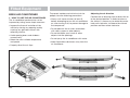
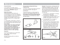
BREAKAWAY CABLES
UK law requires that all caravans are fitted
with a safety device to provide protection in
the unlikely event of separation of the main
coupling while in motion. A device referred
to as a 'breakaway cable' fulfils this
requirement and when fitted as on your
caravan is mandatory.
Purpose
To apply the caravans brakes if it becomes
separated from its towing vehicle. Having
done this, the cable assembly is designed to
part allowing the caravan to come to a halt
away from the towing vehicle.
Identification
A thin steel cable with a red plastic coating
fitted with a means of attachment for
connection to the towing vehicle. Located
directly beneath the coupling head.
Operation
In the event of the main coupling of the
caravan separating from the towing vehicle,
the cable should be able to pull tight,
without any hindrance, engaging the caravan
brakes. The breakaway cable should not
become taut during normal use.
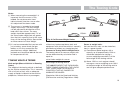
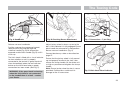
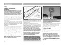
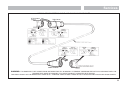
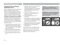
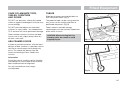
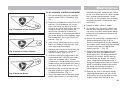
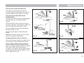
Correct procedure for use
Regularly check the cable and clip for
damage. If in doubt contact your Swift
Group dealer.
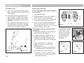
Make sure the cable runs as straight as
possible and goes through the cable guide
fitted underneath the caravan coupling head.
Determine whether or not the towing vehicle
towbar has a designated attachment point
(i.e. a part specifically designated for a
breakaway cable).
Fig. 1
✔
Where a point is designated on the towbar:
• Pass the cable through the attachment
point and clip it back on itself (figure 1).
• Do not clip directly onto the designated
point (figure 2) since the clip is not
designed for use in this way.
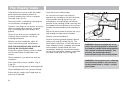
Where there is no designated attachment
point on the towbar:
• Fixed ball: Loop the cable around the
neck of the towball in a single loop only.
See figure 3A and 3B, Page 28.
• Detachable towball: You must seek
guidance on procedure from the towing
vehicle towbar manufacturer or supplier.
Fig. 2
✘
27
The Towing Code
When the breakaway cable is attached,
check to ensure:
a) that the cable cannot snag in use on the
caravan coupling head, jockey wheel,
stabiliser or accessory e.g. bumper
shield, cycle carrier etc.
b) that there is sufficient slack in the cable
to allow the towing vehicle and caravan
to articulate fully without the cable ever
becoming taut and applying the brakes.
Fig. 3A
c) that it is not slack and can drag on the
ground. If left loose, the cable may
scrape along the ground and be
weakened so that it subsequently fails to
do its job. The cable may also be caught
on an obstacle when in motion thus
engaging the caravan brakes prematurely.
Having followed this advice, should you feel
that a satisfactory coupling arrangement
cannot be achieved, consult your Swift
Group dealer or towbar supplier.
MIRRORS
The driver of the towing vehicle must have
an adequate view of the rear.
If there is no rear view through the caravan it
is essential that additional exterior towing
mirrors are fitted. This is mandatory in some
European countries and drivers can face
instant fines if extension mirrors are not fitted.
Caution: Any rear view mirror must not
project more than 200 mm outside:
a) the width of the caravan when being
towed.
b) the width of the towing vehicle when
driven solo.
Note: Any rear view mirror fitted shall be ‘e’
marked and cover the field of view as
stipulated by type approval requirements
(Regulation 33 of the Road Vehicles
[Construction and Use] Regulation 1986).
MOVING OFF
Let the clutch in smoothly.
Allow more engine speed to produce the
power to move the additional weight of the
caravan.
Reduce wear and tear on clutch and
transmission by taking extra care.
Fig. 3B
Change gears smoothly.
Try not to jerk the clutch.
28
The Towing Code
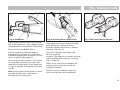
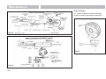
REVERSING
When the towing vehicle is reversing, the
overrun device shaft is pushing in, applying
the brakes via the overrun lever, brake rod
system, bowden cables and the expander
mechanism.
The backwards rotation of the brake drum
causes the secondary brake shoe to collapse
cancelling out the braking effect, allowing the
trailer to move backwards. At the same time
the transmission lever swings back and
compensates for the entire travel.
When reversing up a slope or on a loose
surface the brakes may apply themselves,
Correct maintenance and set up of the
brakes will help prevent this. Incorrect
adjustment of the wheel brakes or Linkages
will result in making reversing difficult.
Proficiency at reversing can only be achieved
with practice and should be first attempted in
a large open area (Fig. A).
Fig. A Reversing
When passing other vehicles allow more than
the normal clearance for driving solo.
Allow longer to get up speed to pass.
Allow for the outfit being twice its normal
length.
Do not suddenly swing out.
SPEED LIMITS
Carry out all manoeuvres as smoothly as
possible.
Normal road towing: 50mph
Use nearside wing mirror to check caravan
has cleared when overtaking.
Motorways (including dual carriageways):
60mph
CARAVAN HANDLING
WARNING: Take care not to foul or
ground caravan chassis whilst
traversing ramps or other obstacles.
IMPORTANT POINTS ESPECIALLY
FOR MOTORWAY DRIVING
1. Caravans may not be towed in the outside lane of a three or four lane motorway. (Reg. 12(2) of the Motorway Traffic
[England and Wales] Regulations 1982).
2. Reduce Speed:
i) In high or cross winds.
ii) Downhill.
iii) In poor visibility.
3. High sided vehicles cause air buffeting so
extra care must be taken when passing or
being passed. As much space as
possible should be given.
Allow for caravan being wider than car.
Do not bump kerb with caravan wheels.
29
The Towing Code
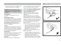
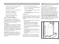
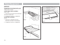
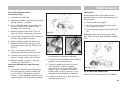
CHANGING A WHEEL
WHEEL BOLT TIGHTENING
1. Leave caravan hitched to towing vehicle
and ensure handbrake is applied.
When refitting a wheel it is ESSENTIAL that
the wheel bolts are tightened to the
recommended torque figure and in the
correct sequence.
2. Lower corner steadies (as safety
measure) on the side that the wheel is
being changed to stabilise the caravan.
3. Use wheel brace to slacken off wheel
nuts on the wheel to be changed.
The sequences necessary to correctly carry
out this work on a 5 stud wheel is as follows:
1
4. Position jack under the axle at the
appropriate jacking point (see fig. B)
5. Jack up the caravan until the wheel for
removal is just off the ground.
5 Stud
3
6. Remove the wheel nuts, wheel trims and
remove the wheel.
4
7. Fit spare wheel and reverse the above
procedure.
5
Ensure clean, dry mating surfaces and
clean, dry bolt/nut sealing areas.
8. Tighten all five bolts, according to Fig. A,
to 88Nm (65lb/ft) for steel wheels or
115Nm (85lb/ft) for alloy wheels using a
torque wrench or have checked as soon
as possible.
Ensure the correct wheel fixings are used,
as supplied with your caravan
IMPORTANT
When a wheel has been removed and
replaced the torque of the wheel nuts should
be re-checked after approximately 15 miles
of running. (See 8 above).
30
Fig. A
2
Fig. B Side Lift Jack
The Towing Code
JACKING POINTS
WARNING: Only jack up your caravan
when it is coupled up to the car with its
handbrake applied and in 1st gear
(engine off).
(v) Drive forward since this attempt to move
up the hill will now not involve pulling the
full weight of the caravan until the car has
gained some traction.
used to raise one side of the caravan by
driving or reversing the caravan onto the
boards. Apply the handbrake and chock the
wheels.
ARRIVAL ON SITE
The positioning of the jockey wheel can be
used to help level the caravan.
Note: Check and observe site regulations.
Ensure that the jack is located in the correct
position, i.e. on the jacking bracket on the
chassis for the AL-KO side mounted jack
(Fig.B). Alternatively the reinforced axle
mounting plate can be used as an alternative
but the chassis member itself MUST NEVER
be used as a jacking point.
All caravans are provided with the facility to
fit AL-KO side jacking points and although a
scissor, trolley or bottle jack may be used,
it is recommended that the side mounted
AL-KO Jacking System should be used.
STOPPING ON A HILL
Pulling off again can sometimes present a
problem. The easy solution is
(i) Carry a good sized wedge shaped piece
of wood with a rope or light chain
attached.
(ii) Attach the other end of the rope to the
nearside rear grab handle.
(iii) Place the wood behind the nearside
caravan wheel.
(iv) Carefully reverse the car slightly back
down the hill, the caravan will stop
against the wedge and turn.
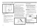
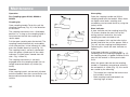
MANOEUVRING YOUR CARAVAN
BY HAND
Lower the corner steadies until they are in
firm contact with the ground.
Note: Care must be taken when
manoeuvring your caravan into position.
Pressure placed on unsupported parts of
front and rear GRP/ABS panels may cause
surface damage cracks to appear “Use the
grab handles provided”.
1. Selecting a pitch
Do not pitch in such a position that your
outfit will obstruct others coming in.
Try to choose an area which is dry, reasonably level and preferably with a hard base.
If you have no alternative but to pitch on a
slope ensure that, for when you leave, you
are facing down the slope.
Fig. C levelling Board
It is good practice to chock the wheels of
the caravan when parked on a slope even
though the caravan brakes are applied.
DO NOT use the steadies as a jack
they are only a means of stabilising
the caravan.
2. Levelling the caravan
Levelling must be carried out in both
directions in order for the refrigerator and
other equipment to function correctly. This
should be done before unhitching the
caravan. Levelling boards (Fig. C) can be
Levelling pads or boards should be used
under the steadies where the ground is soft
or uneven.
31
The Towing Code
In extreme cases where it is necessary to
raise a wheel off the ground for levelling
purposes, further adequate support should
be applied so that the steadies do not take
any undue strain.
Exterior Door
To prevent distortion of the body, the
caravan must be always correctly sited and
levelled. Failure to site the caravan correctly
may prevent the exterior door from closing
properly.
3. Unhitching
Apply the caravan handbrake.
Lower the jockey wheel to the ground.
Disconnect the breakaway cable and road
lighting plugs.
AKS3004
Release the stabiliser by lifting the red
handle. Then lift the exposed black handle
forward until it clicks up, at the same time
winding down the jockey wheel, to lift the
caravan clear of the towing vehicle.
AK160
Operate the handle by depressing the
locking button on the lever mechanism and
lift the handle upwards and forwards, at the
same time winding down the jockey wheel,
to assist in lifting the caravan clear of the
towing vehicle.
When this operation is complete, replace
towball cover and secure the 12N+12S or
13 pin cables in their storage cup(s).
32
Park your vehicle alongside the caravan on
the offside.
SAFETY
AND
SECURITY
Fire ..........................................................................................
Notice ...................................................................................
In Case of Fire ......................................................................
Smoke Alarm.........................................................................
Carbon Monoxide Alarm .......................................................
Fire Extinguishers..................................................................
Children ...................................................................................
Ventilation ..............................................................................
Security ...................................................................................
Caravan Theft .......................................................................
Chassis Number....................................................................
Additional Security ...............................................................
Security Chips.......................................................................
Caravan Insurance ................................................................
AL-KO secure immobiliser ....................................................
34
34
34
34
35
35
36
36
36
36
36
36
37
37
37
Safety & Security
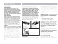
FIRE
Important: Your attention is drawn to the
notice affixed inside the caravan advising on
fire precaution, ventilation and what to do in
case of fire.
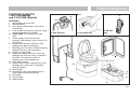
IN CASE OF FIRE
1. Get everyone out of the caravan as
quickly as possible using whichever exit is
the quickest, including windows. Do not
stop to collect any personal items.
2. Raise the Alarm. Call the Fire Brigade.
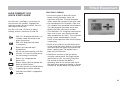
Test Button
3. Turn off the gas supply valve if it is safe to
do so.
4. Turn off the electricity supply at supply
point.
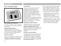
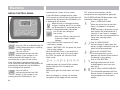
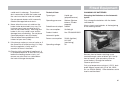
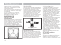
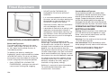
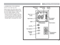
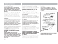
SMOKE ALARM
This is approved by The National Caravan
Council. The NCC requires that all new or
used holiday homes sold by its members are
fitted with a smoke alarm featuring an alarm
silence facility.
Maintenance
Test the smoke alarm every week, e.g. when
doing the vacuuming, by pressing the test
button for at least 10 seconds. The alarm
signal is a penetrating, rapidly pulsating
signal. The alarm sounds as long as the test
button is pressed or there is smoke in the
34
detector. When the alarm goes off, always
check carefully to see that there is no fire
and never remove the battery from the alarm
except when changing it!
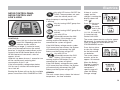
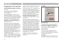
Removing and Replacing the Alarm
Always test the alarm immediately after a
long period of absence. Under the test
button, there is a red control lamp which
twinkles once a minute. This shows that the
battery is correctly connected. If the alarm
does not sound when testing, the battery
must be replaced. The alarm should be
dusted and cleaned regularly with a slightly
damp cloth. In connection with annual
battery change or when required, e.g. false
alarm, clean and vacuum the alarm carefully
using a soft brush.
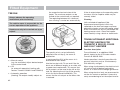
Battery Replacement
Carefully twist the alarm anti-clockwise.
Replace as diagram above.
The battery lasts approximately one year.
About a month before the battery is
completely flat, the alarm emits a short
signal once a minute, this is the signal that
the battery needs changing. The alarm works
as normal during this time.
The battery should be 9 Volt batteries GP
1604,S,A, Eveready 522,216, Duracell
MN1604. Always test the alarm after
changing the battery.
Safety & Security
WARNING: Ensure that batteries are
correctly installed. Positive terminal to
positive contact (marked +), negative
terminal to negative contact. Reversing
a battery in its compartment will
immediately drain the battery and
could damage the smoke alarm.
WARNING: The electronic test button
provides a full test of the unit’s
functionality. DO NOT try to test the
alarm with a naked flame, as this may
present a potential fire hazard.
WARNING: Never use portable cooking
or heating equipment other than electric
heaters that are not of the direct radiant
type, as it is a fire and asphyxiation
hazard.
WARNING: Appliances such as cookers
must not be used for heating.
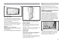
CARBON MONOXIDE ALARM
WHERE A CARBON MONOXIDE ALARM
HAS BEEN FITTED, READ THE FULL USER
INSTRUCTIONS PROVIDED WITH THE
UNIT AS USER INSTRUCTIONS VARY.
What to do if the alarm sounds
If the alarm sounds:
Call the emergency services.
Immediately move to fresh air-outdoors or by
an open door/ window. Do a head count to
check that all persons are accounted for? Do
not re-enter the nor move away from the
open door/ window until the emergency
services have arrived and the vehicle has
been aired out. The alarm returns to its
normal condition.
Never restart the source of a CO problem
until it has been fixed.
ANYONE WITH THESE SYMPTOMS
SHOULD IMMEDIATELY TURN OFF
ALL APPLIANCES AND SEEK
MEDICAL ATTENTION.
MAINTAINANCE
The alarm should be cleaned using a
vacuum or soft brush.
NEVER IGNORE THE ALARM
No detergents should be used to clean the
casing
NEVER REMOVE THE BATTERY
WITHOUT REPLACING.
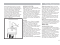
FIRE EXTINGUISHER
CO ALARMS DETERIATE WITH AGE
AND MUST BE REPLACED NO LATER
THAN EVERY 5 YEARS
CARBON MONOXIDE
Known as the silent killer, Carbon Monoxide
is an invisible, odourless and tasteless gas,
What are the symptoms of carbon monoxide
poisoning?
Early symptoms of carbon monoxide (CO)
poisoning can mimic many common
ailments and may easily be confused with flu
or simple tiredness. Symptoms to look out
for include: tiredness, drowsiness,
headaches, giddiness, nausea, vomiting,
pains in the chest, breathlessness, stomach
pains, erratic behaviour, visual problems.
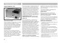
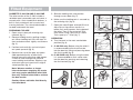
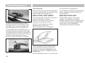
It is recommended that a 1kg (2lb) minimum
capacity dry powder fire extinguisher be
carried inside your caravan at all times.
When using a dry powder extinguisher it is
suggested that the caravan be evacuated
until the powder has settled, to avoid
inhalation.
A fat pan fire should not have a fire
extinguisher aimed at it. It should be
smothered with a fire blanket.
WARNING: Provide one dry powder fire
extinguisher of an approved type or
complying with ISO 7165, of at least 1kg
capacity, by the main exterior door and
a fire blanket next to the cooker.
Familiarise yourself with the instructions
on your fire extinguisher and the local
fire precaution arrangements.
35
Safety & Security
ESCAPE PATHS
Petrol/Diesel Fumes
The fitting of a tail pipe to your car exhaust
will reduce the possibility of fumes entering
your caravan through the ventilation points.
It is important that you do not block escape
paths to emergency exits with obstructions
or hazards.
Note: Never allow modification of electrical
or LPG systems and appliances except by
qualified persons at an authorised Swift
Group dealership.
CHILDREN
Do not leave children alone in the caravan in any
event. Keep potentially dangerous items out of
reach, as at home e.g. matches, drugs etc.
SECURITY
VENTILATION
All caravans comply with BS EN 721. The
ventilation points on your caravan are fixed
points of ventilation which are required by the
European Standards.
All caravans have ventilation at high level and
low level which have been calculated to suit
the individual needs of your caravan.
High level ventilation is achieved by means of
the roof lights and washroom roof ventilators.
The low level ventilators are positioned
underneath the oven housing. Some models
with sliding doors have two vents located
underneath the sliding doors.
Under no circumstances must these vents be
blocked or obstructed.
It is advised that fixed ventilation points are
checked and cleaned (if necessary) on a
regular basis using a small brush and a
domestic vacuum cleaner.
Additional night time ventilation is obtained
36
Fig. A Chassis Number
by releasing the window catches and placing
them in the second groove. Note the
windows are not sealed from rain in this
position.
As the ventilation levels are calculated to suit
each models requirements there should be
no modifications made which may result in
reduced ventilation levels.
WARNING: Do not obstruct ventilation.
Caravan theft
The theft of a caravan can occur in the most
unlikely circumstances; from a motorway
service area, even from an owner’s driveway.
Secure all windows and doors when your
caravan is unoccupied even if only for a short
length of time.
Chassis number
Record your caravan chassis number which
can be found on the front offside section of
the drawbar (Fig. A) or any of the eye level
windows.
Make a note of this number in the space
provided at the front of this handbook and
make a separate note of the number to keep
safe at home.
Additional security
Consider fitting any device which might deter
or prevent intrusion by thieves.
A hitch lock cover prevents towing of
the caravan.
Safety & Security
A wheel lock prevents towing of the caravan
and removal of the wheel.
Customers are advised to identify their
caravan with a method for subsequent
identification if other forms of identification
have been altered or removed.
Free crime prevention advice about securing
your caravan, protecting your valuables,
property marking, either at home or whilst on
site, can be obtained from the Crime
Prevention Officer through your local Police
Station.
Phantom satellite monitoring system
Depending on model and specification, your
caravan may be fitted with a Phantom
Tracker security device. This device is fitted
in a concealed location, and linked to the
alarm within the caravan. No maintenance of
the unit itself is required.
Should the device be activated by the alarm
or other trigger, the system will alert a
dedicated call centre. The call centre will
then contact you via agreed telephone
numbers, and if appropriate may request you
to obtain a crime number from the local
police force. The call centre will then directly
with the police officer in charge in the
relevant control centre to retrieve the caravan
as quickly as possible.
It is important that separate documentation
relating to the installation is reviewed when
you receive your new caravan, to ensure that
the device is properly registered and correct
contact details are held by the call centre.
Please be aware that an annual subscription
charge is applicable to the continued use of
the device and call centre, and that any
change of ownership or contact details
should be passed to Phantom without delay.
For reference the contact phone number for
Phantom is 0800 1074663.
NOTE: To ensure operation of the
Tracker, a leisure battery in a good
state of charge must remain
connected to the caravan at all times.
SECURITY CHIPS
A special security chip is concealed within
the body of every caravan. This chip
contains the individual identity of your
caravan and can only be read by using a
special decoder. Your local police can obtain
the use of a decoder by contacting C.R.I.S.
on telephone no: 01722 411430
CARAVAN INSURANCE
It is recommended that the caravan and its
contents should be insured against theft.
It is essential to check with your car
insurance company to ensure you are
covered when towing your caravan.
AL-KO SECURE IMMOBILISER
The AL-KO immobiliser is fitted as standard
on some models, optional on others. When
fitted the 4 part kit specified below is
supplied with your caravan. Your kit will
contain : Part A
Box containing security components.
consisting of:
-
1off High security locking bolt
-
1off High security locking bar socket key
-
1off Barrel lock
-
2off Barrel lock keys
-
Instruction manuals in CD and paper
format.
-
Security registration card and reference
number
Part B
Wheel specific insert assembly consisting of:
-
Red coloured wheel insert lozenge
assembled with the locking bar and circlip
Part C
-
1off Wheel spanner
Part D
-
Kit bag.
37
Safety & Security
YOU MUST REGISTER YOUR KEY WITHIN
ONE MONTH OF THE DATE OF
PURCHASE. SHOULD YOU FAIL TO DO
THIS, YOU WILL NOT BE ABLE TO ORDER
A SPARE KEY!
- Within your AL-KO kit will find an exclusive
security number.
- Please register your card by telephoning
0870 7576788 or 0044 1926 818500.
- You will need to provide a password and
provide an answer to a prompting security
question.
- Make a note of your password and keep it
in a safe place.
- Keep your registration card safe.
- Take your registration card with you when
you are travelling with the caravan.
- Always keep your registration separate from
the lock.
must be inspected at an AL-KO Approved
Service Workshop.
- Always keep the key in a safe place.
OPERATION
- Keep the lock set and registration card
separate from the key.
To operate the jack, insert the metal Jack
Collar into the lower edge of the bracket
- The lock parts and key do not have a
registration number, therefore keep the
registration card in a safe place.
- Caravans with twin axles have two locks,
keep each lock set in a separate place.
The sets are not interchangeable!
AL-KO OPERATING INSTRUCTIONS
- READ THE AL-KO OPERATING
INSTRUCTIONS AND ACT IN
ACCORDANCE WITH THEM.
- INSTRUCTIONS FOR GENERAL USE.
- FOLLOW ALL SAFETY INSTRUCTIONS AS
WELL AS THE WARNING INFORMATION.
SAFETY INFORMATION
- IT IS RECOMMENDED FOR EASE OF FIT
THAT A SIDE-LIFT JACK BE USED.
- Always secure the caravan against rolling
away (chock or couple to a towing vehicle).
- KEEP THE OPERATING INSTRUCTIONS
- Never leave Secure parts (key, adaptor,
registration card) in the caravan.
- Always remove AL-KO Secure before
moving the caravan.
- After any attempt of theft has been made
on a locked AL-KO Secure, the caravan
38
mounting holes have been pre-punched into
the longitudinal members as standard.
THE AL-KO SIDE LIFT JACK
(SUPPLIED AS STANDARD ON SPECIFIC MODELS ONLY)
The AL-KO Side Lift Jack has been
specifically developed to aid the often
difficult process of changing a wheel on
caravans. It is suitable for fitment to the
AL-KO chassis, from, appropriate bracket
SERVICES
Connection of Services ......................................................... 40
Water ....................................................................................... 40
Typical Water Schematic Drawing ........................................ 40
Whale Fresh Water Inlet (if fitted).......................................... 41
Flojet Automatic Water System Pump ...................................41
Shure-flo Pump ..................................................................... 43
Inboard Water Tanks and On-line Water Systems................ 45
Whale Aqua Source .............................................................. 47
Gas ........................................................................................... 49
Typical Gas Schematic Drawing ........................................... 49
General Information .............................................................. 50
Types of Gas ......................................................................... 50
Gas Safety Advice................................................................. 51
Thermal Insulation Heating ................................................... 52
Electricity ................................................................................ 53
Instructions for Electricity Supply ......................................... 53
Overseas Connection............................................................ 53
Wiring of Connecting Cable and Caravan Mains Inlet.......... 55
Typical Appliance Consumption Figures............................... 56
Services
WATER
Connection of services is dealt with under
the separate headings.
Water system schematic caravan
without water tank
TAPS
FILTER / PUMP / ACCUMULATOR
In all cases users should become familiar
with the equipment manufacturers’
instructions.
Advice and leaflets, if not supplied with the
caravan, can be obtained from the suppliers
of the equipment.
AQUASOURCE
DRAIN VALVES
WATER
INLET
FILTER &
HOSE
(if fitted)
NON
RETURN
VALVE
DRAIN
VALVE
C
H
Before making connections of any
description to the caravan or its equipment,
ensure that ALL equipment is turned off.
WATER
HEATER
WATER
CARRIER
Water system schematic caravan
with water tank
TAPS
FILTER / PUMP / ACCUMULATOR
AQUASOURCE
FILTER &
HOSE
WATER
INLET
NON
RETURN
VALVE
SELECTOR
VALVE
DRAIN VALVES
(if fitted)
DRAIN
VALVE
C H
WATER
CARRIER
WATER TANK
OVER
FLOW
WATER
HEATER
ISOLATION VALVE
40
Services
WHALE FRESH WATER INLET
(IF FITTED)
The hose and carbon filter assembly
supplied with your caravan, is to be
connected to the water inlet on the exterior
of your caravan, to draw water from an
external container.
Place carbon filter fitted to hose, into water
container.
Insert plug into wall socket and close lid to
lock plug in place (see image)
Adjust dust cover over water container
opening. Please note dust cover cover
should not be secured to water container as
air must be allowed to enter container to
replace water being drawn out.
Water will flow from the open tap after filling
the water heater. This can take a few
minutes if the heater is empty. The water
may be at first grey in colour which is quite
normal, the discolouration is due to harmless
media being flushed out of the new filter
cartridge.
When water is flowing smoothly close hot
tap and open cold tap to expel any
remaining air in the system. Repeat this at
each tap / shower mixer in the caravan.
FLOJET AUTOMATIC WATER
SYSTEM PUMP
FEATURES
Self-Priming
Dry Running
Soft Noise Absorbing Mounts
Snap-in Port Fittings
Built-in Bypass Less Pulsation
Corrosion Resistant Materials
Meets ISO 8846
The system is now ready for use. Hose can
be inserted into plug groove (see image) to
keep filter off ground while refilling water
container. Keep socket lid shut at all times
when plug is removed.
SPECIFICATIONS
When the caravan is left unattended or water
supply has been allowed to empty, to
prevent the pump running continuously
(which can cause pump damage) turn the
pump switch on the control panel to the
‘OFF’ position.
Pump: Three chamber diaphragm design
Self-priming up to 9 feet suction lift; Pump
able to run dry without damage
Ensure drain valves in water system and
at water heater are in closed positions
(See page 40 for more detail)
A pack containing two replacement filters
(product code WF3000) is available.
Filters will need to be replaced after filtering
3000 litres (approx. 33 days of normal use).
These filters are not designed for removing
bacteria and should not be used on water
supplies of an unknown bacterial quality.
Open one hot tap (kitchen sink) within
caravan.
Take care to retain the o-ring seal when
replacing filters.
Motor: Permanent Magnet, Ball Bearing
Totally Enclosed. CE Models are fully
suppressed.
OPERATION
With pump switch off and battery fully charged,
fill water tank, open all faucets, then turn pump
switch on. Water will begin to flow. When the
water is free of air, turn faucets off. Remember,
you are filling the water heater and pipes.
When all valves are shut-off, pump will stop.
Should pump fail to stop, turn switch off and
see the trouble shooting.
With 12V power available to appliances
within the caravan, switch the pump
‘ON/OFF’ switch on the control panel to the
‘ON’ position.
41
Services
TROUBLESHOOTING
WARNING: BEFORE SERVICING PUMP,
TURN OFF PUMP AND DRAIN WATER
FROM SYSTEM!
Worn pump bearing (excessive noise)
Punctured pump diaphragm (pump leaks_
Defective motor
SYSTEM CARE AND MAINTENANCE
Winterizing
Failure to prime
Motor operates, but no pump discharge
Restricted intake or discharge line
Air leak in intake line
Debris in pump
Punctured pump diaphragm (pump leaks)
Crack in pump housing
Allowing water to freeze in the system may
result in damage to the pump and
plumbing system.
Motor fails to turn on
Loose wiring connection
Pump circuit has no power
Blown fuse
Pressure switch failure
Defective motor
For specific winterizing and drainage
procedures refer to page 49.
Pulsating flow
Restricted pump delivery. Check discharge
lines, fittings and valves for clogging or
undersizing
1. Drain the water tank (if fitted). Open tank
drain valve. You may use the pump to
drain the tank by opening all the faucets in
the system. Allow the pump to operate
until) the tank is empty. Do not operate the
pump more than 15 minutes continuously
Pump fails to turn off after all fixtures
are closed
Empty water tank
Insufficient voltage to pump (low battery)
Punctured pump diaphragm (pump leak)
Defective pressure switch
Low flow and pressure
Air leak at pump intake
Accumulation of debris inside pump
and plumbing
42
Non-Toxic antifreeze for potable water may
be used with Flojet pumps. Follow
manufacturers recommendations.
Do not use automotive antifreeze to
winterize potable water systems. These
solutions are highly toxic and may cause
serious injury or death if ingested.
2. Open all faucets and purge the water
from the plumbing system. Turn power to
the pump off. Be sure that all the water
from the drain lines are drained
Remove quick connect inlet and outlet
fittings from the pump and turn the pump on
to pump out remaining water from the pump
head. Be sure to have a catch pan or a rag
under the pump to prevent water from
spilling. Turn the pump off once the
plumbing is empty. Leave the fittings
disconnected from the pump until the
system is ready to be used again. Make a
note on your tank filler that the plumbing is
not connected.
Be sure that all faucets are left open to
protect against damage to the plumbing.
Sanitizing
Portable water systems require periodic
maintenance to deliver a consistent flow of
fresh water. Depending on use and the
environment the system is subject to,
sanitizing is recommended prior to storing
and before using the water system after a
period of storage.
Services
SHURE FLO PUMP AND
ACCUMULATOR ASSEMBLY
Drive
Assembly
Valve
Assembly
2
Upper Housing
Switch Assembly
1
3
Motor
4
Pump Head
5
General Information
Winterizing
Shurflo water pumps meet the essential
health and safety requirements and are in
conformity with the EU EMC directive
89/336/FEC as specified in EN 55014 (1993).
If water is allowed to freeze in the system,
serious damage to the plumbing and the
pump may occur. Failures of this type will
void the warranty. The best guarantee
against damage is to completely drain the
water system. However, non-toxic antifreeze
for fresh water, available at local RV centres,
may be used.
Shurflo realises that in many instances our
pump is being installed as a replacement
pump within an existing system. The
following guidelines should be considered to
achieve optimum pump operation.
Mounting
SHURFLO RV FRESH WATER
PUMP
INSTALLATION AND OPERATION
Shurflo’s patented RV Fresh Water Pumps for
drinking water were developed to delivery
smooth, consistent flow at all ranges of
operation, while drawing low current. The
balanced diaphragm design incorporates
precision ball bearings for long life. Each
motor is equipped with an integral thermal
breaker and all units are CE approved. RV
fresh water pumps are enclosed to prevent
incidental moisture from entering; however,
they are not intended for environment where
splashed water is present. When installed
correctly, RV Fresh Water Pumps provide
years of quiet operation.
The pump can be at the same level or below
the water tank. It may be positioned above
the water tank if needed, as it is capable or a
6 ft. (1.8m) vertical prime. Horizontal inlet
tubing will allow priming to 30 ft. (9m).
The pump should not be located in an area
of less than one cubic foot (0.03m) unless
adequate ventilation is provided. Excessive
heat may trigger the integral thermal breaker
and interrupt operation. When the
temperature drops, the breaker will
automatically reset and start the operation.
The pump may be mounted in any position.
The mounting feet are intended to isolate the
pump from the mounting surface; over
tightening, flattening, or use of oversized
screws will reduce the ability to isolate
vibration/noise.
CAUTION: Do not use Automotive
Antifreeze to winterize drinking water
systems. Such solutions are highly toxic.
Ingestion may cause serious injury or
death. To properly drain the system
perform the following:
Drain the water tank. If the tank doesn’t
have a drain valve open all taps allowing the
pump to operate (15min. ON. 15 min. OFF)
until the tank is empty.
Open all the taps (including the lowest valve
or drain in the plumbing) and allow the pump
to purge the water from the plumbing, then
turn the pump OFF.
Using a pan to catch the remaining water,
remove the plumbing at the pump’s
inlet/outlet ports. Turn the pump ON,
allowing it to operate until the water is
expelled. Turn OFF power to the pump once
the plumbing is emptied. DO not reconnect
pump plumbing. Make a note at tank filler
as a reminder: “Plumbing is Disconnected”.
43
Services
All taps must be left open to guard against
any damage.
TROUBLESHOOTING
Vibration induced by road conditions or
transporting can cause plumbing or pump
hardware to loosen. Check for system
components that are loose.
Many symptoms can be resolved by simply
tightening the hardware. Check the following
items along with other particulars of your
system.
WILL NOT PRIME/SPUTTERS:
(No discharge/motor runs)
- Is the strainer clogged with debris?
- Is there water in the tank, or has air
collected in the hot water heater?
- Is the inlet tubing/plumbing sucking in air at
plumbing connections (vacuum leak?)
- Is the inlet/outlet plumbing severely
restricted or kinked?
PUMP WILL NOT START/BLOWS CIRCUIT
- Proper voltage with the pump operating
(±10%)
- Electrical connections, fuse or breaker,
main switch and ground connection.
- For debris in pump inlet/outlet valves or
swollen/dry valves
- Is the motor hot? Thermal breaker may
have triggered; it will reset when cool.
- Pump housing for cracks or loose drive
assembly screws
- Is voltage present at the switch? Bypass
the pressure switch. Does the pump
operate?
PUMP WILL NOT SHUT-OFF/RUNS WHEN
TAP IS CLOSED:
- Charging System for correct voltage
(±10%) and good ground.
- For an open or grounded circuit, or motor;
or improved sized wire.
- For seized or locked diaphragm assembly
(water frozen?).
- Output side (pressure) plumbing for leaks,
and inspect for leaky valves or toilet
- For air trapped in outlet side (water heater)
pump head
NOISY OR ROUGH OPERATION:
- For plumbing which may have
vibrated loose
- Is the pump plumbed with rigid pipe
causing noise to transmit?
- Does the mounting feet that are loose or
are compressed too tight
- For loose pump head to motor screws
(3 long screws)
- The motor with pump head removed.
Is noise from motor or pump head?
RAPID CYCLING:
- Pressure switch shut-off adjustment
- Water filter/purifier should be on separate
feed line
- For restrictive plumbing, flow restrictors in
taps/shower heads
LEAKS FROM PUMP HEAD OR SWITCH:
- For correct voltage to pump (±10%)
- For loose screws at switch or pump head
- For loose drive assembly or pump
head screws
- Switch diaphragm ruptured or pinched
- Are the valves or internal check vale held
open by debris or is rubber swollen?
44
- Pressure switch operation/adjustment
incorrect, refer to shut-off adjustment for
switch
- For punctured diaphragm if water is present
in the drive assembly
Services
LIMITED WARRANTY
Shurflo warrants its RV Duty Fresh Water
Pumps to be free of defects in workmanship
and materials under normal use, for two
years beginning with the purchase date of
the unit.
SHURE FLO ACCUMULATOR
181-2xx
This warranty does not extend to any Shurflo
products, which have been misapplied,
improperly installed or altered outside the
Shurflo factory.
Accessories & Fittings
Shurflo’s warrants its accessories and fittings
to be free of defects in workmanship and
materials (under normal use) for one year
beginning with the purchase date of the
accessory or fitting.
This warranty does not extend to any Shurflo
products, which have been misapplied
and/or improperly installed.
All Products
Shurflo is not responsible nor will it reimburse
for labour necessary to remove and reinstall a
pump and/or fittings and accessories if found
defective.
Shurflo’s obligation under this warranty policy
is limited to the replacing or repairing
(whichever it deems advisable) any such part,
which is returned to Shurflo’s factory with
transportation charges pre-paid and which
upon Shurflo’s inspection is found
defective under the terms of this warranty.
In the majority of installations the Shure Flo
pump is mounted with a Shure Flo
accumulator. The Shure Flo accumulator
tank is a bladder type pressure storage
vessel and/or pulsation dampening device
designed to hold water under pressure. The
accumulator tank provides additional water
storage to assist the pump in meeting the
total demands of the system. It extends
pump life by eliminating pump pulsation
on/off. The accumulator also makes small
amounts of water available at a moments
notice without cycling the pump.
To work with the 30psi pump installed, the
accumulator pressure should be set at 18psi,
+/- 5psi, and before installation the
accumulator is factory set with a pre-charge
of 20psi.
During the life of the accumulator the precharge pressure should not require frequent
adjustment, but checking the pressure
annually is advisable. The accumulator is
fitted with a Schreider valve on the top of the
chamber which allows the pre-charge
pressure to be checked and/or adjusted. The
pressure can be checked with a tyre
pressure gauge, and adjustments can be
made if necessary with a bicycle hand pump.
Please note that the pre-charge pressure of
20psi must not be exceeded for long term
storage or during system non use.
INBOARD WATER TANKS AND
ON-LINE WATER SYSTEMS
Please refer to the water system schematic
on page 40 with reference to these
instructions. Two model specific systems are
in use:
- Pressure switched systems in caravans
with no internal water tank as already
described.
- Pressure switched systems in caravans
with an internal tank, featuring a single
pump with valve arrangement to cover all
water system requirements.
45
Services
INTERNAL TANK OPERATIONS –
PRESSURE SWITCHED SYSTEM
When an internal water tank is fitted options
exist to supply water to the taps and shower
from either the internal tank or the external
supply.
Before using the water system ensure that
the drain valves both in the hot and cold
circuit and adjacent to the water heater are
in the closed positions (See page 40)
taps in the caravan will allow this to happen,
this should be repeated at the hot and cold
position of each tap / mixer, until water is
flowing freely in all cases.
TO USE THE INTERNAL WATER TANK TO
SUPPLY THE TAPS:
- Check the water level gauge on the control
panel to confirm the water level within the
tank.
TO USE AN EXTERNAL WATER CARRIER
TO SUPPLY THE TAPS:
- Close the tank isolation valve on the mid
right of the tank installation, (see diagram
page 40).
- Ensure that the external hose and filter
assembly is connected, and suspended in
the external water container with water
present.
- Turn the selector valve to the left of the
tank installation anti-clockwise to connect
the supply from the internal tank to the
water pump.
- Close the tank isolation valve on the mid
right of the tank installation, (see diagram
page 40)
- Switch the pump switch to the ‘ON’
position on the control panel
- Turn the selector valve to the left of the
tank installation clockwise to connect the
external supply to the water pump.
- Switch the pump switch to the ‘ON’
position on the control panel
If the taps within the caravan are closed, the
pump will run until the correct pressure is
attained within the plumbing. If the water
system is being operated for the first time or
from a drained condition, air in the system
will need to be expelled. Opening the internal
46
If the taps are closed within the caravan the
pump will run until the correct pressure is
attained within the plumbing system. If any
of the taps are open water will flow from
those taps as soon as the pump is switched
on, unless the system is being run for the
first time or from a drained condition.
TO FILL THE INTERNAL TANK:
- Ensure that the external hose and filter
assembly is connected, and suspended in
the external water container with water
present.
- Open the tank isolation valve on the mid
right of the tank installation, (see diagram
page 40)
- Turn the selector valve to the left of the tank
installation clockwise to connect the
external supply to the water pump.
- Ensure all of the taps within the caravan are
in their closed positions.
- Switch the pump switch to the ‘ON’
position on the control panel
Water will now be drawn from the external
container by the internal pump and forced
into the internal tank. Water will flow into the
tank until either the external container is
empty, or the internal tank overflows.
Progress can be monitored using the water
level gauge on the control panel.
Services
WHALE AQUASOURCE
The Aquasource allows mains water to be
connected to the caravan in place of the inlet
hose and filter, as shown on the water
system schematics. The Whale Aquasource
can only be used with the Whale water inlet.
The hose features pressure reduction valves
which reduce mains water pressure to a level
which will prevent damage to the caravan
water system.
If a pressure switched system is installed and
the Aquasource is plugged in instead of the
hose and filter, the operation of the water
system is unchanged. The pump will still run
when an internal tap is opened or during a
tank filling operation.
When using an Aquasource system, do not
sleep or leave the vehicle unattended without
turning off the mains tap.
WARNING: It is not recommended to
tow with water in the onboard water tank
as this could affect stability.
WARNING: Do not under any
circumstances connect your caravan to
the mains water supply without the
pressure reducer fitted. Damage will
occur to the caravan's water system.
47
Services
GUIDANCE ON CLEANING PORTABLE
WATER TANKS AND THE WATER SYSTEM
IN TOURING AND MOTOR CARAVANS
The water systems, and in particular storage
tanks, in caravans are susceptible to
contamination by bacteria if care is not taken
with their use and cleaning. The symptoms
caused by bacterial contamination are not
purely limited to gastro-intestinal diseases,
but may also manifest themselves as ear,
nose, throat, eye or skin infections. It is
therefore important that you carry out the
following procedure prior to using the
caravan each time, even if you boil or filter
all water you use for drinking.
5. The solution should be emptied from the
container.
6. The opening of the container should be
cleaned thoroughly with an appropriate
prepared wipe impregnated with a
sterilant.
7. The container should be inverted whilst
stored overnight (if possible).
8. The container must be filled with mains
water only and mains water only should
be used for the above cleaning
procedure.
9. On no account should garden hoses be
used to fill water tanks.
Separate Water Containers
For Systems:
1. All water remaining in the container
should be disposed of so that the
container is empty.
1. Drain down the system (open all taps to
allow air in, enabling the system to drain
quickly).
2. The outside of the container should be
thoroughly cleansed and washed down to
remove any dirt, dust or other contaminant.
Water at a suitably hot temperature
containing an appropriate detergent is
recommended for this purpose.
2. Remove any water filters fitted, and
replace with a short length of hose or
empty filter cartridge (this will ensure the
filter is not affected by the disinfectant/
sterilant solution).
3. Water should be put in the container,
swirled around, then emptied out.
4. The container should then be totally filled
with water containing an appropriate
sterilant solution and allowed to stand for
the recommended contact time (e.g.
Milton for 15 minutes).
48
3. Fill the system by using the pump with a
disinfectant/sterilant solution (check that
the solution at full strength appears at all
taps/showers). Allow to stand for the
recommended period of time.
4. Drain the system completely.
5. Thoroughly clean the outside of all
taps/connectors with a cloth soaked in
the disinfectant/sterilant.
6. Flush the system through with clean
drinking water until no traces of
disinfectant/sterilant can be detected at
any tap.
7. Replace the filter.
Suitable sterilising chemicals are available
from your caravan dealer, accessory shop,
chemist or home-brew shops. It is not,
however, recommended to use bleach or
sodium metabisulphite.
This guidance has been prepared with the
kind co-operation and assistance of The
Environmental Health Department of The
Borough Council of King's Lynn and West
Norfolk.
WARRANTY
Products are guaranteed from the date of
purchase against defects in materials and
workmanship. If the unit proves faulty, return
it to your supplier with proof of purchase and
purchase date. Please note that frost
damage is not a valid warranty claim.
The manufacturer retains the right to repair
or replace the unit. The manufacturer cannot
be held responsible for claims arising from
incorrect installation, unauthorised
modification or misuse of the product. The
above does not affect your statutory rights.
Services
REGULATOR
ISOLATOR VALVE
TEST POINT
BBQ POINT
(MODEL SPECIFIC)
Typical gas
schematic drawing
49
Services
GAS
GENERAL INFORMATION
Gas Bottles
Bottled Liquified Petroleum Gas (LPG) is the
most convenient portable source of fuel for
your caravan. Make sure that heating and
cooking appliances and the gas cylinders are
switched off before you move the caravan.
Regularly check flexible gas hose, joints and
connections for tightness. Finally make sure
that each gas appliance is working efficiently
to the recommendations of the appliance
manufacturers.
Only use gas bottle cylinders that are located
within their dedicated position within the front
gas bottle housing, never extend hose - hose
lengths must not exceed 400mm
Regulator
Your caravan is supplied with a wall mounted
gas regulator plumbed inside the gas bottle
compartment. The regulator and all appliances
work at a harmonised 30mb pressure, which
work with Butane and Propane gas.
Pressure regulation system in this vehicle has
a fixed working pressure of 30 mbar with a
flow rate of 1.5 kg/h and complies with the
requirements of EN 12864 annex D.
Note: Regulator valves should always be in
the ‘OFF’ position when towing.
50
Fig. A Gas Bottle Compartment
Gas Hoses
A high pressure hose, or pigtails as they are
being called must be used with the new style
regulator (Fig B).
LPG bottles i.e. Propane, Butane and
Camping Gaz cylinders all have varying bottle
adaptor connections. It is important to check
you have the correct hose and adaptor to suit
your gas bottles. Push on hoses are no
longer permitted under the new regulations,
The new high-pressure hoses have threaded
connections and must be securely attached
to the regulator and to the gas bottle.
Ensure that there is a constant rise in the
flexible gas hose between the gas bottle
outlet and the regulator elbow.
WARNING: Inspect flexible gas hose(s)
regularly for deterioration and renew as
necessary with the approved type, in any
case no later than 5 years after the date
of manufacture marked on the hose.
Fig. B
Gas Regulator
WARNING: Ensure hoses do not
become entangled in door mechanism.
Cylinder compartment
All cylinder compartments have two universal
plastic mouldings fitted to the floor of the
compartment that are designed to fit both
steel and BP Gas Light cylinders.
TYPES OF GAS
Butane
Butane is supplied in the U.K. in green, blue
or aluminium bottles.
All these have a male left hand thread
EXCEPT for Camping Gaz which has a
special female right hand thread and Calor
7kg and 15kg and aluminium bottles which
have a special clip-on connection.
A 7kg bottle is recommended for butane
gas use.
Services
Continental bottles usually have a male left
hand thread similar to but not identical with
U.K. butane.
Butane is suitable for use at temperatures
down to 2°C but will not work below that.
Propane
Propane is supplied in Red, or partly red
bottles which have a female left hand
threaded connector.
Scandinavian countries use the same
connector.
Germany and Austria supply propane with a
male connection.
Propane will work at temperatures as low as
-40°C and is therefore suitable for all winter
caravanning.
A 6kg bottle is recommended for propane
gas use.
GAS SAFETY ADVICE
WARNING: If you smell gas or suspect
a leak and if it is safe to do so, isolate
the gas appliances and turn off the gas
bottles at the regulator. Evacuate the
caravan and ventilate. Seek professional
advice as to the cause of the leak.
WARNING: Inside outlet sockets shall
only be used with dedicated appliances
i.e. equipment supplied with the Touring
Caravan. No gas appliance shall be used
outside when connected to an inside
socket.
LPG is not poisonous.
b) Avoid naked lights when connecting or
changing a cylinder.
Bi-products are harmless.
c) Check the flexible hose frequently.
There is danger if all air and oxygen were
excluded.
d) The gas is heavier than air and therefore
sinks to the lowest point.
(Ventilation holes must be kept clear at all
times).
e) Keep bottle gas containers outside (and
protected against frost). If they must be
kept inside make sure they are well away
from heat.
Facts about LPG
LPG has been given a smell by the
manufacturers in order to identify leaks.
Awning Spaces LPG Appliance Exhaust
There is no danger of pollution of an
enclosed awning space by the LPG exhaust
from a refrigerator venting into it, as awning
spaces are generally well ventilated.
Space heaters may produce sufficient
exhaust to pollute the awning space, if it is
totally enclosed, from a general comfort,
smell and hygiene point of view. In the
extreme case there could be a build up of
carbon dioxide to a dangerous level.
Caravan owners are advised to allow some
fresh air circulation in the awning space
when such appliances are in use.
WARNING: Do not use appliances with a
different working pressure to 30mbar.
WARNING: Maintain adequate spacing of
combustible materials from sources of
heat.
WARNING: Do not use independent
portable gas appliances inside the
vehicle.
WARNING: A BBQ point inlet valve,
if fitted, must only be used for the
connection of portable LPG appliances.
PRECAUTIONS
a) Never look for a leak with a match.
Always use a soap solution or its
equivalent when testing connections.
Do not operate any electrical apparatus
whatsoever, especially light switches. If
the leak is not obvious, the caravan
should be evacuated and qualified
personnel consulted.
51
Services
Always read individual appliance
instructions
VENTILATION
All ventilation complies with BSEN 721 and
vents should not be obstructed in any
manner as this could lead to insufficient fresh
air. In this case the confined atmosphere
becomes depleted of oxygen which leads to
the formation of the highly poisonous gas
‘carbon monoxide’. Carbon Monoxide is
odourless, colourless and tasteless and will
rapidly cause unconsciousness and death
with little or no warning prior to collapse.
THERE IS NO DANGER WHEN ADEQUATE
VENTILATION IS PROVIDED.
Roof-mounted Flue installations
All flue installations should be inspected
once a year throughout their length for
corrosion. Flues should be replaced if any
sign of perforation is found. Ensure that the
replacement is of an approved type.
CONNECTION
Ensure that the gas regulator hose is
correctly connected to the gas cylinder in
gas bottle compartment and that the hose
connection is tight.
Gas bottles must be fully located, seated at
the base of the bottles and restrained by the
strap provided in the dedicated compartment
position.
Straps are positioned to suit 6kg and 7 kg
bottles.
WARNING: If using cylinders other than
those recommended, the user must
ensure these are adequately supported,
ventilation openings must not be
obstructed and the cylinders must not
cause damage to other fixtures and
fittings located in the compartment.
Open ended gas hoses must always be
protected from dirt and insects
Before turning on the gas supply at the
regulator, ensure that all gas operated
equipment in the caravan is turned off.
All gas equipment (except barbecue) is
supplied through a central Gas Manifold
System which has individual isolation taps
for each appliance (Fig A), as follows:
Fig. A
52
RED
WHITE
-
Water Heater
Space Heater
BLUE
GREEN
YELLOW
-
Fridge
Oven
Barbecue (if fitted)
Note: the external barbecue point is fed from
the main feed through a built in integrated
isolation valve. See schematic layout for
details.
THERMAL INSULATION HEATING
Your caravan has been designed to achieve a
thermal insulation and heating level for
specific climatic conditions when tested
according to the procedure in EN1645-1.
The classifications are as follows:
GRADE 1
A caravan with an average thermal
transmittance (u) that does not exceed
1.7w/(m2k).
GRADE 2
A caravan with an average thermal
transmittance (u) that does not exceed
1.7w/(m2k) and which can achieve an
average temperature difference of at least
20k between inside and outside temperatures when the outside temperature is 0°C.
GRADE 3
A caravan with an average thermal
transmittance (u) that does not exceed
1.2w/(m2k) and which can achieve
an average temperature difference of at
least 35k between inside and outside
temperatures when the outside temperature
is -15°C.
Services
ELECTRICITY
As with electricity in the home, care must be
exercised when handling mains electricity.
Your attention is drawn to the following
notice as laid down by the Institute of
Electrical Engineers.
INSTRUCTIONS FOR ELECTRICITY
SUPPLY
On arrival at caravan site
1. Before connecting the caravan installation
to the mains supply, check that
(a) both 12N, 12S or 13 pin plug(s) and
hitch have been disconnected from
the towing vehicle, once disconnected
the 12N, 12S or 13 pin plug(s) should
be placed in the holder(s) provided to
ensure protection against mechanical
damage and the elements,
(b) the mains supply is suitable for your
installation and appliances, i.e.
whether it is AC or DC and whether
it is at the correct voltage and
frequency,
(c) your installation will be properly
earthed. Never accept a supply from
a socket outlet or plug having only
two pins, or from a lighting outlet,
and
(d) any residual current device (earth
leakage circuit breaker) in the mains
supply to the caravan has been
tested within the last month.
In case of doubt, consult the site owner or
his agent.
2. MAKE SURE THAT THE SWITCH AT
THE SITE SUPPLY POINT IS OFF.
3. Lift the cover of the electricity inlet
provided on the caravan, and insert the
connector of the supply flexible cable.
4. Remove any cover from the socket outlet
provided at the site supply point, and
connect the plug at the other end of the
supply flexible cable to this. Switch on
the main switch at the site supply point.
Note: Use mains cable fully uncoiled and
protect from traffic.
IT IS IMPORTANT THAT THE MAIN
SWITCH AT THE SITE SUPPLY POINT
SHOULD BE SWITCHED OFF, THE
SUPPLY FLEXIBLE CABLE
DISCONNECTED, AND ANY COVER
REPLACED ON THE SOCKET OUTLET AT
THE SITE SUPPLY POINT BEFORE
DISCONNECTING THE FLEXIBLE CABLE
FROM THE CARAVAN. IT IS DANGEROUS
TO LEAVE THE SUPPLY SOCKET OR
SUPPLY FLEXIBLE CABLE LIVE.
Because touring caravans are generally left
unused for long periods in the open, it is
strongly advised that the mains installation is
inspected periodically to ensure that it is
safe to use. The IEE Wiring Regulations
recommend that mains installations in
touring caravans are re-inspected every
3 years by a qualified person who should
sign and issue a periodic inspection report
NOTE: The manufacturer recommends
annual inspections.
Suitably qualified persons acceptable to the
NCC to sign and issue inspection and
completion certificates are:
• an approved contractor of the National
Inspection Council for Electrical
Installation Contracting* or
• a member of the Electrical Contractors’
Association
• a member of the Electrical Contractors’
Association of Scotland
53
Services
• a qualified person acting on behalf of the
above (in which event it should be stated
for whom he is acting).
*The names and addresses of Approved
Contractors in any locality (there are over
10,500 in the UK) can be obtained from
Electricity Shops, or direct from:
NICEIC, Vintage House,
37 Albert Embankment, London SE1 7UJ
Telephone: 0171 582 7746
WARNING: CURRENT CONSUMPTION
IN THE CARAVAN MUST NOT EXCEED
16 AMPS OR THE PITCH PERMITTED
MAXIMUM IF THIS IS LESS THAN 16
AMPS.
IT IS DANGEROUS TO ATTEMPT
MODIFICATIONS AND ADDITIONS
YOURSELF. LAMPHOLDER—PLUGS
(BAYONET-CAP ADAPTORS) SHOULD
NOT IN ANY CIRCUMSTANCES BE
USED.
The names and addresses of members of
the Electrical Contractors’ Associations can
be obtained direct from:
OVERSEAS CONNECTION
ECA, Esca House,
Palace Court, London W2 4HY
Note: Connection to a mains voltage supply
OVERSEAS requires particular attention.
Telephone: 0171 229 1266
Care must be taken when connecting
supplies abroad since the supplies can be of
REVERSE POLARITY.
ECA of Scotland, 23 Heriot Row
Edinburgh EH3 6EW
Telephone: 0131 225 7221
The significance of REVERSE POLARITY is
that when equipment is switched off it may
not be electrically isolated.
The only certain way of making equipment
safe is to unplug it.
It is useful to have a means of checking
polarity of the mains supply, especially when
touring overseas. There are available several
proprietary makes of equipment for testing
polarity.
54
If it can be achieved, it is preferable to
connect live to live, and neutral to neutral to
maintain full electrical protection.
WARNING: Never allow modifications
of electrical or LPG systems and
appliances except by qualified persons.
230V MAINS ELECTRICAL
EQUIPMENT POWER
CONSUMPTION
Note: It is possible that the 230v mains
electrical equipment may not all operate
simultaneously. A typical UK motorhome site
mains hook up point provides a maximum
output of 10 amps and on some continental
sites the available output may be as low as
5 amps. If your loading exceeds the site
supply it may trip the site circuit breaker.
Please check the available mains supply with
your site operator.
Similarly loadings on each circuit breaker
within the caravan should be observed.
A label positioned close to the MCB’s will
identify which appliances within the caravan
are fed from which MCB. Consulting the
table on page 55 in conjunction with this
label, will give an indication of which
appliances can, and cannot, (site supply
allowing), be operated simultaneously.
Services
WIRING OF CONNECTING CABLE AND CARAVAN MAINS INLET
WARNING: IT IS ESSENTIAL THAT CONNECTIONS ARE MADE EXACTLY AS SHOWN. IF TERMINAL MARKINGS ARE NOT IN ACCORDANCE WITH THE
DIAGRAM THEY MUST BE IGNORED. IF IN DOUBT CONSULT A QUALIFIED ELECTRICIAN.
THE LEGAL LENGTH OF THE MAINS INLET CABLE IS 25 ± 2 METRES. WHEN IN USE IT MUST BE FULLY UNCOILED AND PROTECTED FROM TRAFFIC.
55
Services
TYPICAL APPLIANCE CONSUMPTION FIGURES
230 Volt
Appliance/ Item
Watts
Amperes
Refrigerator
115 W
0.5 amp
Ultraheat Space Heater
500 W
2.2 amp
Ultrastore Water heater
Cooker
12 Volt
Watts
Amperes
Only when towing
LP Gas
grams/hour
12 - 17.5 g/h
12 W
1000 W
4.5 amp
12 W
2000 W
8.5 amp
12 W
850 W
3.7 amp
1.0 amp
30 to 280 g/h
Not applicable
120 g/h
Hotplate 1
Not applicable
Not applicable
161 g/h
Hotplate 2
Not applicable
Not applicable
110 g/h
Hotplate 3
Not applicable
Not applicable
73 g/h
Not applicable
Not applicable
Hotplate 4
800 W
3.5 amp
Grill
Not applicable
Not applicable
117 g/h
Oven
Not applicable
Not applicable
125 g/h
Not applicable
Battery Charger
430 W
1.9 amp
Not applicable
Lighting 230V (based on 2x 40 W bulbs)
80 W
0.3 amp
Not applicable
Lighting 12V (based on 10 W bulb)
Avtex 15" LCD TV
Not applicable
1.5 amp
0.8 amp
Not applicable
Not applicable
43 W
3.6 amp
Pressure switched pump
Not applicable
48 W
4.0 amp
Not applicable
Radio/ CD player
Not applicable
12 W
1.0 amp
Not applicable
Omnivent
345 W
Not applicable
10 W
position 1
Not applicable
15 W
1.2 amp
Not applicable
position 2
Not applicable
30 W
2.5 amp
Not applicable
Not applicable
50 W
4.0 amp
Not applicable
position 3
Air Conditioning unit
1200 W
5.25 amp
Not applicable
Not applicable
Microwave (factory fit)
1200 W
5.3 amp
Not applicable
Not applicable
Note: These are approximate figures for guidance only.
56
ELECTRICAL
EQUIPMENT
NE 171 Control Panel .............................................................
NE 183 & NE189 Control Panel & Control Unit ....................
NE 190 Control Panel .............................................................
NE 143RM Power Supply Unit ..............................................
Consumer Unit .......................................................................
Separate Charger ...................................................................
Nordelettronica 12V DC Distribution Unit ............................
Habitation Relay .....................................................................
Battery Box ..............................................................................
Solar Panel Connection .........................................................
Generator Guidelines .............................................................
58
59
62
64
65
66
66
66
67
70
71
Electrics
NE171 CONTROL PANEL
CAR POSITION
The switch can be placed in this position
should the caravan battery become
discharged and a 230V supply is not
available. First of all the towing vehicle
should be electrically connected with the
caravan via the 12S connector. Care is
needed to avoid discharging the battery in
the tow vehicle to an extent that the engine
cannot be started.
Please note that when towing and using the
12V element of the fridge, correct positioning
of the car/van selector switch may be
required – see details in the ‘Towing Code’
section of this handbook.
CAR / VAN SELECTOR SWITCH
A car/caravan selector switch is provided on
this control panel and should be used in the
following way:
CARAVAN (VAN) POSITION
When in this position 12V DC power is
available from the caravan battery to power
all 12V circuits. If the charger is switched ON
the caravan battery will be charged up by
the charger / transformer unit.
CENTRAL POSITION
When in this position with the charger switch
ON, power is provided to all 12V circuits via
the charger / transformer only. With the
charger off all 12V DC circuits are isolated.
58
PUMP SWITCH AND INDICATOR
Included on this panel is a pump isolation
switch. The isolation switch illuminates the
LED above the switch when in the on
position. The isolation switch is used to
isolate the 12V DC power to the pump in the
event of a pump fault, or merely for use as a
safeguard against unwanted pump
operation.
BATTERY CONDITION METER
The Red display on the control panel shows
the voltage of the caravans 12V DC circuits
measured at the control panel. This figure
will change as the charger is switched ON or
OFF, when 12V DC appliances are switched
ON or OFF, and as the state of charge of the
caravan battery changes.
With the charger switched ON it is possible
for the voltage shown to be up to 13.8V.
With the charger switched OFF or no 230V
supply present, and with the car/selector
switch in the VAN position, the reading gives
an indication of caravan battery voltage.
- A voltage below 11V, when no 12V DC
appliances are operating, would indicate
the battery requires charging.
- A voltage above 12V would indicate that
the battery is in a good state of charge.
- If a figure between 11V and 12V is shown
the battery should be re-charged if desired.
Maintaining a leisure battery in a good
state of charge will assist in ensuring
maximum service life for the battery.
Electrics
NE183 CONTROL PANEL
NE189 CONTROL UNIT
LOW & HIGH
Key with LED to turn ON/OFF the
PUMP. The pump does not work
when the control panel is off .
When the pump is working the LED
is blinking.
Key for turning LIGHT group A on
and off.
Key for turning LIGHT group B on
and off.
CONTROLS:
Press this key to turn the control
panel ON. Depending upon the
software version, either a
momentary or longer (1 second or more)
press may be required to turn the control
panel on. In stand-by mode (without active
controls) the NE183 control panel with the
NE189 control unit consumes a total of
approx. 40 mA.
Hold this key down for over 1 second to turn
off the control panel, reducing total
consumption to just 1 mA.
Key with LED to
connect/disconnect the VAN
Battery. If the charger is not
working and the VAN battery is not
connected the system will go off.
If the VAN Battery voltage remains under
10,0V more than two minutes, the System
will automatically disconnect the VAN
Battery and the System will go OFF.
Key with LED to
connect/disconnect the CAR
Battery. If the charger is not
working and the CAR battery is not
connected the system will go off.
If the leisure battery voltage drops below
10V for over 2 minutes the control panel
turns itself off.
If the CAR Battery voltage remains under
10,5V more than two minutes, the System
will automatically disconnect the CAR
Battery and the System will go OFF.
Starting the System will use the first available
power source from VAN, CHARGER or CAR.
VIEWING:
The main screen always shows the internal
temperature , the time and date.
If there is a mains
supply and the
charger is working the
display shows the
icon (
).
Press this key once
to view
the water
level in the
fresh water tank (0,
1/4, 2/4, 3/4 and 4/4)
if connected with
Control Unit HIGH.
The screen shown remains active for approx.
30 seconds. If connected with Control Unit
LOW, this page can be disabled in the
PROGRAMMING section.
Press the key twice
to view the voltage
for the leisure and
car batteries.
The screen shown
remains active for
approx. 30 seconds.
When the Battery
Charger is working
and no battery is
connected a
specific page will
show the Battery
Charger voltage.
59
Electrics
The screen shown remains active for approx.
30 seconds.
Display contrast can be adjusted by turning
the white pin on the back of the panel.
PROGRAMMING:
Hold down this key for over 3
seconds to enter the
programming menu.
Use the arrow keys to change page.
Press the enter key (
) repeatedly to enter
the page and select the value to be
changed.
The arrow keys are used to increase or
reduce the selected value, whereas the
cancel (
) key is used to quit the function
and save the figure.
The following pages are available:
– Regulation of date and time
– Regulation and enabling of clock. When
the clock is enabled, the main screen
shows the icon (
). The clock will sound
for 30 seconds; press any key to stop it.
– Enabling of tank alarms: fresh water tank
empty. When this happens a buzzer is
generated and at the same time the display
shows the tank viewing window. The tank
alarm does not work with the control panel
off or the engine / alternator running.
– Enabling of flat Van and Car batteries.
Whenever the Van or Car battery drops
60
below 10V (or 10,5) for over 30 seconds a
buzzer is generated and at the same time
the display shows the viewing window for
battery voltage. The battery alarm does not
work with the control panel off or the
engine / alternator running.
– Enabling of key beeper.
– Programming dimmer level of the LED;
after 50 seconds without any operation on
the Panel all the LED light will be reduced.
At any press the light come On again.
ADDITIONAL FUNCTION:
The SYSTEM NE183-NE189 provides some
information about typical fault:
OVERLOAD PUMP: When the pump tries to
work but there is a problem in the
pump circuit.
If the Pump is changed, please use the
same type otherwise some false warning will
be displayed.
OVERVOLTAGE: If an overvoltage coming
from the battery charger is detected, the
battery and the loads will be disconnected.
NO CONNECTION: The communication
system between the Control Panel and the
Consumer Unit is not working.
LOW BATTERY: Starting the System but all
the available power source are lower then
9,0 V.
MEMORY BATTERY:
On the back of the NE183 control panel
there is a buffer battery (LITHIUM 3V
CR2032) to maintain the time and various
programming functions if 12V energy supply
for the PCB fails.
Electrics
61
Electrics
NE190 CONTROL PANEL
connected the system will not switch.
If the CAR Battery voltage remains under
10,5V more than two minutes, the System will
automatically disconnect the CAR Battery, E4
is blinking for 30 seconds.
When the main is connected and the
charger is working, the LED is on. When
one of the battery is connected too, the
Charger is charging the battery connected.
Key to view the voltage of
the system.
– only main LED on, the panel will
show the charger’s output
Voltage.
COMMAND:
– only CAR/VAN LED, the panel will show
the battery voltage.
OFF and the Leisure battery will be
connected to the engine power generator.
The SYSTEM NE189-NE190 provide some
information about typical fault:
Error 1 OVERLOAD PUMP
When the pump tries to work but
there is a problem in the pump
circuit.
If this message is displayed, all the
push button will be disabled for 5
seconds. If the Pump is changed,
please use the same type otherwise
some false warning will be
displayed.
Error 2 OVERVOLTAGE
– MAIN + BATTERY LED, the panel will show
the system voltage.
An overvoltage is detect from the
battery charger, the battery and the
loads will be disconnected.
Key with LED to
connect/disconnect the VAN
Battery. If the charger is not
working and the VAN battery is not
connected the system will not switch.
When the NE190 Panel is connected to a
System with water level if you push again
the TEST, the panel will show the Clear
Water Level:
The communication system
between the Control Panel and the
Fuseboard is not working.
If the VAN Battery voltage remains under
10,0V more than two minutes, the System will
automatically disconnect the VAN Battery,
E4 is blinking for 30 seconds.
After 30 second without any push button
used the panel will switch off the number
display and the LED will reduce the
brightness.
Starting the System but all the
available power source are less
then 9,0 V.
Key with LED to
connect/disconnect the CAR
Battery. If the charger is not
working and the CAR battery is not
When push again the indications will come
ON.
The connection between the Tank
Sensor and the Fuseboard is in the
wrong sequence or one lead is
broken
Key with LED to enable/disable the
PUMP. When the pump is working
the LED is blinking.
62
Error 3 NO CONNECTION
Error 4 LOW BATTERY
When the engine is running, all the load
(exception of the fridge) will be switched
Error 5 TANK LEADS PROBLEM
Electrics
63
Electrics
POWER SUPPLY UNIT NE143RM
The NE143RM power supply unit controls
230V AC power and provides 12V DC output
as follows:
Mains 230V AC - Mains Module with
earth leakage protection and over
current protection.
The NE143RM power supply units are
designed to operate on a mains supply of
207V - 253V AC (for use with low continental
voltages). The 40 amp RCD gives protection
against earth faults and also acts as the
main switch. The mains module then has
three MCB's, the ratings of which are
appropriate to the appliances and circuits
within the caravan.
For details of the circuits linked to each
MCB, please refer to the label positioned
close to the NE unit. Each MCB carries an
indication of its nominal current rating, and a
table on page 55 of this handbook gives
details of the loadings for each appliance. It
may not be possible to operate
simultaneously all appliances linked to an
MCB, please also consider the total current
loading relative to the 230V AC supply
available to the caravan.
12V DC - The NE143RM power supply unit
employs a fully automatic 12V DC charger,
which can operate with a wide range of 230V
AC input voltages, and provides a stable
64
output voltage even under load. The unit can
provide up to 18 amp (@12V) continuously.
NE143RM
The battery charger uses an algorithm which
makes it possible to significantly reduce
charging time and avoid permanent damage
to batteries. It starts charging at maximum
current until the battery reaches a voltage of
14.4V, then charging takes place at a
constant voltage of 13.8V. In this state the
recharge current gradually decreases and
the battery can be left permanently
connected to the charger without causing it
any damage.
The battery charger is fitted with circuitry
which will protect it in the event of electrical
or thermal overload. Should the current draw
exceed the rated output of the unit, then it
will begin shutting down. This will probably
be noticed as dimming of the 12V lighting.
On the removal of the excessive load the
charger will automatically recover. To protect
against overheating there is an electronic
thermal protection circuit, which will operate
should the temperature of the unit rise above
a safe level. If this happens then the output
will shut off until the temperature has
dropped back to a safe level.
In addition to the mains module, three
switches are present on the front of the
NE143RM
SPACE HEATER
This switch can be used to isolate power to
the 230V element on the Truma space
heater. This is in addition to the selection of
'OFF', '500W', '1000W' or '2000W' on the
space heater's own control module.
WATER HEATER
This switch controls 230V power to the
Truma Ultrastore water heater. This is the
only means of turning the electric element in
the water heater on or off.
CHARGER
This switch controls the charger within the
NE143RM. As previously stated the charger
Electrics
is fully automatic and does not require
switching on or off in normal operation.
However if 230V input current is limited,
turning the charger off may allow use of
other 230V appliances.
When this model of NE power supply unit is
fitted a separate 12V DC fusing arrangement
can be found at the front of the caravan
layout, as detailed on page 61.
CONSUMER UNIT
The three switches shown as MCB's
(Miniature Circuit Breakers) take the place of
conventional fuses but are more convenient.
Having too many appliances switched on at
the same time will trip the MCB's. This is a
safety measure (for appliance ratings see
consumption table, 230V column). Additionally
in the event of a fault the MCB will 'trip', i.e.
the switch will automatically move to the off
position. After eliminating the fault or reducing
the load the MCB can be re-set by switching
back to the on position (against the spring
pressure in an upwards direction).
If an earth fault develops or a person
touches a live piece of equipment, the
leakage of current to earth should
immediately operate the RCD (Residual
Current Device) and 'trip' the switch for this
module to the OFF position. This switch is
only re-settable after elimination of the fault.
To re-set, operate the switch as for the
MCB's.
The consumer unit when fitted acts as the
main switch for the caravan 230V system,
allowing isolation of all 230V circuits. It forms
part of a modular power system along with a
12V distribution unit and separate charger.
The unit gives both overload (MCB) and
earth leakage protection (RCD) for the
electrical supply in your caravan.
Periodically the RCD should be checked by
operating the button marked 'T'. The unit
should immediately switch to the OFF
position. If the unit does not switch off, then
a qualified electrician should be consulted. If
the unit does switch off, the test is complete
and the switch can be re-set restoring the
supply back to normal.
For normal operation all RCD and MCB switches
on the unit should be in the ON position.
Three smaller switches feature on the lower
part of the unit:
SPACE HEATER
This switch can be used to isolate power to
the 230V element on the Truma space
heater. This is in addition to the selection of
'OFF', '500W', '1000W' or '2000W' on the
space heater's own control module.
WATER HEATER
This switch controls 230V power to the
Truma Ultrastore water heater. This is the
only means of turning the electric element in
the water heater on or off.
CHARGER
This switch controls the charger within the
NE143RM. As previously stated the charger
is fully automatic and does not require
switching on or off in normal operation.
However if 230V input current is limited,
turning the charger off may allow use of
other 230V appliances.
65
Electrics
Please note that if the caravan is fitted with
Alde or Truma Combi water/space heater
equipment, the switch marked WATER
HEATER isolates the supply of 230V to the
appliance and the switch marked SPACE
HEATER is not used.
SEPARATE CHARGER
If fitted the NE143 charger/power supply unit
is a fully automatic 12V DC charger, which
can operate with a wide range of 230V AC
input voltages, and provides a stable output
voltage even under load. The unit can
provide up to 18 amp (@12V) continuously.
The battery charger uses an algorithm which
makes it possible to significantly reduce
charging time and avoid permanent damage
to batteries. It starts charging at maximum
current until the battery reaches 14.4v, then
charging takes place at a constant voltage of
13.8v. In this state the recharge current
gradually decreases and the battery can be
left permanently connected to the charger
without causing it any damage.
The battery charger is fitted with circuitry
which will protect it in the event of electrical
or thermal overload. Should the current draw
exceed the rated output of the unit, then it
will begin shutting down. This will probably
be noticed as dimming of the 12V lighting.
On the removal of the excessive load the
charger will automatically recover. To protect
against overheating there is an electronic
66
thermal protection circuit, which will operate
should the temperature of the unit rise above
a safe level. If this happens then the output
will shut of until the temperature has
dropped back to a safe level.
NORDELETTRONICA 12V DC
DISTRIBUTION UNIT
When the NE143RM power supply unit is
fitted, a separate 12V DC distribution unit
can be found in the front bed area of the
caravan. This unit is responsible for fusing
arrangements for all 12V DC circuits in the
caravan, i.e. fuses for internal lighting and
appliances, road lighting and also tow
vehicle supplies.
Details of the circuits protected can be found
in the electrical schematic contained within
the service handbook. Labelling on the
distribution unit also identifies fuse allocation.
Automotive type blade fuses are mounted on
the top face of the unit. Only ever replace a
fuse with another fuse of the same rating.
HABITATION RELAY
To conform to European Safety Standards
(EMC), all caravans have been equipped with
a habitation relay.
This relay is actuated when the 12N/12S or
13-pin plugs are connected to the tow
vehicles sockets and the car ignition is
turned on.
The relay automatically isolates all 12V
equipment within the caravan, excluding the
fridges 12V power supply, from the car.
Electrics
THETFORD BATTERY BOX
The Thetford Battery Box is intended to
accommodate an auxiliary battery in your
caravan. The Battery Box has a CE socket
to connect to a 230 V power supply. Inside
the Battery Box there is the option to fit
several sockets and outlets.
• Before removing a battery you should
always check for spillages by touching
the Soft Tray on the outside surface and
sensing for any liquid spills. If you think
that liquid has been spilt, you should
ensure that the Soft Tray and battery are
lifted together so that spillages will not
occur.
PRECAUTIONS AND SAFETY
INSTRUCTIONS
• Use caution when mounting the battery,
as batteries contain acid liquids which
can cause severe injuries and damage
when handled incorrectly. Refer to the
instructions on the battery.
• Use protective clothing and glasses when
handling a leaking battery, and avoid
direct contact to the skin, eyes and
respiratory organ.
Should a battery leakage occur, please
act according to the instructions supplied
by the manufacturer of the battery. Act
with caution as caustic substances are
present in the battery.
• No smoking is allowed in the area of the
Battery Box.
67
Electrics
INSTRUCTION
WARNING!
• Use precaution when mounting the
battery, as batteries contain acid liquids
which can cause severe injuries and
damage when handled incorrectly. Refer
to the instructions on the battery.
• No smoking is allowed in the area of the
Battery Box!
• Please note that the CE socket has a
max of 16 amp.
• The Thetford Battery Box is designed
for use with foot mounted batteries.
These are recognisable by the rim
around the bottom edge of the battery.
This rim will locate against the back wall
of the Battery Box and the angle metal
bracket, which is screwed into place
when the battery is fitted. The depth of
the battery including rim should be
between 173mm and 175mm.
• This product meets the latest version of
the EN 1648 part 1 and 2 standard.
Before placing the battery inside the
Battery Box, the adjacent battery should
be placed into the Soft Tray and rested
on the ground adjacent to the Battery
Box. Carefully connect the electrical
wires (the red cable attaches to the +
pole and the black cable to the - pole of
the battery).
68
Note! Incorrect connection of the cables will
cause a short circuit with potential
hazardous consequences. After mounting
the terminals, lift the battery together with
the Soft Tray into the middle of the Battery
Box compartment. Push the Soft Tray with
battery to the back of the Battery Box, into
the safeguard bulge. If necessary shift the
Soft Tray to the right or left until the battery
is in place in the safety area (see photo 1).
The battery is located in the compartment by
the manual clamping plate. This has to be
screwed to the front of the box (screw is
enclosed in package). Please ensure that the
Soft Tray is pulled up tightly (to remove
creases) before the plate is tightened. The
rounded edge of the clamp prevents damage
to the Soft Tray. Do not apply extreme force
to the screw.
When disassembling, follow this procedure
in reversed order. Note! Always check the
Soft Tray for acid first! If found, take safety
precautions (such as protecting clothing,
body and especially the eyes). In case of
contact with acid, immediately rinse with
plenty of water. Follow regulations
concerning these chemicals.
Tip! Generally, car workshop and gas station
employees are familiar with this matter.
When attaching the 220/230 volts cable on
the CE socket, the maximum recommended
thickness of the cable is 10 mm. When
closing the door, the attached cable is to be
fed through the slot at the bottom right of
the door.
Photo 1
Photo 2
Electrics
CLEANING AND MAINTENANCE
• Use protective clothing and glasses when
handling a leaking battery, and avoid direct
contact to the skin, eyes and respiratory
organ.
• Should a battery leakage occur, please act
according to the instructions supplied by
the manufacturer of the battery. Act with
caution as caustic substances are present
in the battery.
• Always remove the battery and the power
cable before carrying out any maintenance
of the product.
• Before removing the clamps switch off all
appliances.
• No smoking is allowed in the area of the
Battery Box.
• Use a soft cloth or sponge and a nonacid/abrasive detergent when cleaning the
Battery Box and Soft Tray.
• To check if any acid is present in the Soft
Tray, simply press it softly. A strong smell
from the Soft Tray may also indicate spilled
acid. The battery can be filled again with
acid collected from the Soft Tray. Disposal
through local drains is possible and legally
permitted, on condition that the acid is
mixed with water equalling 50 times the
amount of acid. It is often possible to
dispose of acid at gas stations.
• Before the camping season or extensive
travelling, check the Soft Tray for faults and
replace if necessary.
• The cleaning of the Battery Box and Soft
Tray should only be done after all power
sources have been switched off, in order to
prevent a hazardous situations.
THETFORD WARRANTY
1. The Thetford Battery Box is warranted to
the original purchaser for 3 years from the
date of purchase.
2. The warranty covers replacement of parts
arising from defects and workmanship
and from the inability of the Battery Box
to perform its intended function.
3. In case of a defect apply to original
dealer or Thetford Service Center with
proof of purchase.
position where it will be exposed to
higher temperatures will invalidate the
warranty and could lead to an adverse
effect on the product.
5. Thetford products considered to be
defective may be returned prepaid
directly to Thetford. Any items received
which are judged by Thetford to be
covered under warranty will be dealt with
accordingly. Defective products not
considered to be covered by warranty will
incur repair, handling and return carriage
costs.
6. No other warranty is given and no
personal representative is authorised to
make any warranty or assume liability by
words or action under any warranty other
than that is contained herein.
4. Defects, which in our judgement occurred
from misuse, negligence or accident, are
not covered by the warranty. In addition,
the warranty does not apply if the
product is installed or handled improperly,
if the product has been altered in any
way, has been repaired by unqualified
persons, or if the serial number and/or
date has been altered or removed.
- As the Battery Box is manufactured from
polypropylene, it is resistant to
temperatures up to 60 degrees
Centigrade. Installing the battery box in a
69
Electrics
BATTERY INSTALLATION
Under normal circumstances it should not be
necessary to remove the battery other than
for routine inspection of terminals and
“topping up”.
WARNING: Explosive gases may be
present at the battery. Take care to
prevent flames and sparks in the vicinity.
Your caravan has been fitted with an in-line
fuse between the battery terminal and strip
connector. It is recommended that the fuse
rating fitted in this location does not exceed
20 amps.
WARNING: Switch off all appliances
and lamps before disconnecting the
battery.
Smoking is prohibited around the
battery compartment.
To preserve the life of your leisure battery
and charger please observe the following:
i) Do not leave all 12V lights powered at the
same time as this will drain your leisure
battery more rapidly.
ii) If all 12V lights must be powered
together, ensure the battery is 'in-circuit'
i.e. selector switch in the 'van' position
and that the battery charger is turned on.
70
iii) For optimum performance use the
transformer/charger unit with a leisure
battery attached.
BATTERY
It is recommended that a good quality
rechargeable leisure battery is always in
circuit when the system is in use.
A deep cycling heavy duty 12V battery
should be purchased to provide power for
lights and other electrical appliances.
A proprietary brand leisure battery with a
minimum of 85 Amp capacity is
recommended.
Note: 85 Amp batteries and above should
be checked dimensionally before
purchasing, to ensure fitment within the
battery compartment, as brands vary in size.
It should be remembered that batteries
suitable for the electrical demands of a
caravan differ in design from those for use
with a car, and whilst the system may
operate with a car battery it is strongly
recommended that only a leisure type
battery, maintained in good condition is
used. The battery should be kept topped up
at all times.
Note: Some models may have more than
one 12V socket fitted, the 6 Amps indicated
is available from the 12V socket provided no
other 12V socket is used at the same time.
SOLAR PANEL CONNECTION
POINT
A connection point has been included in the
caravan electrical harness to take a 12V
supply from an aftermarket solar panel (or
similar device), to the caravan leisure battery.
The solar panel must provide a fused and
regulated output in order to connect to this
point. The connection point can be found
inside the caravan adjacent to the battery
box, in close proximity to the battery box
fuse. Through the floor close to the battery
box is a cable pass through, allowing a pair
of wires from an externally located device to
pass from exterior to interior to meet the
connection point. This cable pass through
will be capped both internally and externally
with a cable entry gland.
A kit of parts is available from your caravan
supplier which provides the mating half of
the connection point. (The White rectangular
connector found inside the caravan is a two
way JST-LR type connector). For further
assistance in identifying the connection, wire
colours leading to the connector are detailed
in the wiring schematic in your caravan
service book.
Electrics
GENERATOR GUIDELINES
• Lack of regular servicing can be the
cause of most generator problems,
gensets under 2kW are mainly dependent
on engine speed for output frequency
and voltage, poor or no servicing may
cause the engine speed governor to run
the genset engine too fast. Therefore
frequency and output voltage can rise
above the specification of the machine
data plate i.e. 230V at 50Hz, this may
cause damage to electrical/electronic
equipment (such as battery chargers).
• A generator should always be run for a
few minutes prior to connection with the
caravan or motorhome electrics, to allow
it to warm up and the output to settle to a
steady level.
• The AC output of generators is often
derived from an AC alternator, rectified to
DC then inverted back to AC. In essence
this means the output sinewave may not
be very smooth and may not run
sophisticated electronics efficiently. Some
of the new wave of gensets are more
sophisticated in their production of a
sinewave output and are more suited to
run electronic equipment.
• If in doubt consult your genset dealer or
manufacturer for advice.
71
FITTED
EQUIPMENT
SAS Mobile Alarm System ................................................................. 74
Truma Ultrastore Water Heater ......................................................... 76
Truma S 3002 P and S 3002 Auto Space Heater ............................ 79
TEB Fan .............................................................................................. 82
Truma Ultraheat for S 3002 (P), S 5002 and
S 55 T Heaters ............................................................................... 82
ALDE Compact 3010 Quick Start Guide .......................................... 85
ALDE Compact 3010 ......................................................................... 86
Refrigerator ...................................................................................... 102
Thetford Absorber Refrigerators ................................................... 102
Stoves Hobs, Grills & Ovens ........................................................... 111
Spinflo Oven ..................................................................................... 115
Using the Hob burners .................................................................. 115
Using the the Grill ......................................................................... 115
Using the the Oven ....................................................................... 116
Microwave Oven .............................................................................. 117
Thetford Cassette C-200 CW & C-200 CWE .................................. 121
Thetford C250 CWE Cassette Toilet .............................................. 125
External Barbeque Point .................................................................. 130
TV Inlet ............................................................................................... 131
Supplier Fitted/Supplied Entertainment Equipment .................... 132
Status 530 directional TV & FM radio antenna ............................. 133
WING omni-directional TV antenna ............................................... 133
Bedding ............................................................................................. 134
Cassette Blinds and Flyscreens ..................................................... 136
Doorscreen ....................................................................................... 137
Roof Lights and Windows ........................................................ 137-138
Air Conditioning ............................................................................... 142
Ash Framed Doors ........................................................................... 147
Tables ................................................................................................ 147
Shower .............................................................................................. 148
Fixing of Awnings ............................................................................ 148
Fitted Equipment
SAS210 MOBILE ALARM SYSTEM
Using the latest microprocessor technology
the SAS210 provides all year round
protection for your caravan.
Please read all sections of these user
instructions before attempting to operate the
SAS210.
To part set the alarm (modes c or d) hold
down the arm button until the desired mode
has been selected:
movement sensor lens, move the tilt
adjustment lever forward until the green light
illuminates. Note the position of the lever.
Hold down and release after 2 long beeps,
mode (c) selected.
Now move the lever backwards and again
note the position of the lever when the green
light illuminates.
Hold down and release after 3 long beeps,
mode (d) selected.
If you are unsure of any of the following
points, please contact your local dealer or
the manufacturer direct (see point 5), on
page 75
Note: if the arm button is continually held
down the system will disarm and then repeat
the above sequence.
1. Operation
The SAS210 Alarm System comes complete
with a 120° x 360° Passive Infra Red
movement sensor that detects body
movement within the vehicle.
Arm/Disarm
The SAS210 Alarm System is armed and
disarmed by pressing the button on the key
fob remote controller.
PIR Movement Sensor
The alarm has four modes of operation:
If you are leaving pets within the vehicle the
system should be armed in mode (c) to
prevent nuisance triggering.
a) Disarmed
Tilt Sensor
b) Fully armed with internal movement
sensor and tilt sensor active
The SAS210 Alarm System has an inbuilt tilt
sensor that detects tilting of the vehicle
during the hitching process. If the tilt sensor
is not set correctly, the alarm will not arm
and will indicate a fault by beeping 4 times in
rapid succession.
c) Partially set with only the tilt sensor active
d) Partially set with only the movement
sensor active.
The alarm indicates arm/disarm status by
beeping. One beep = armed, two beeps in
quick succession = disarmed.
During normal (on the flat) operation there is
no need to alter the tilt sensor.
If the vehicle is parked on a steep slope it
may be necessary to adjust the tilt sensor.
With the alarm disarmed, while viewing the
74
Set the lever mid way between the two
positions.
Remember to return the lever to the centre
(locked) position when returning to 'on the
flat' use.
Alarm Siren
When the alarm is triggered the siren will
sound for 2 minutes. Following the 2 minute
period the alarm will then deactivate for 15
seconds then rearm.
The alarm siren can be turned off at any
point by pressing the key fob button. If the
movement sensor caused the alarm trigger,
the alarm will give a standard 'two beeps in
quick succession' disarm indication. If the tilt
sensor caused the alarm trigger, the alarm
will give 'two beeps in quick succession'
followed by a further 'two beeps in quick
succession'.
Sleep mode
The SAS210 Alarm System incorporates a
sleep mode that extends battery life over a
long period of time.
Fitted Equipment
If a charged leisure battery is fitted and is
supplying 12V to the alarm system the alarm
will operate in standard 'quick response'
mode.
If the alarm is operating from the internal
alarm battery only, the alarm will operate in
'slow response' battery saving sleep mode.
In this mode you will need to press and hold
the arm/disarm button for up to 3 seconds
to arm or disarm the alarm.
2. Key Fobs
The SAS210 Alarm System comes complete
with 2 key fob remote controllers. If an
additional controller is required these can be
ordered from your supplier.
Key Fob Battery Replacement
1. Remove the key fob from your key ring.
2. Prise the casing apart near the key ring
fixing slot.
3. While holding the base part of the casing,
prise out the old Lithium battery and
replace with a new CR2032 battery.
Ensure the [+] terminal is located towards
the outer case.
4. Relocate the two casing halves and snap
together.
3. Battery
4. Specification
The SAS210 Alarm System incorporates a
3.3Ah sealed lead acid battery that is
charged from the vehicles 12V supply. This
battery has been selected to run the alarm
without any external supply voltage for up to
9 months depending on ambient
temperature/initial charge.
Control Box
Supply voltage:
Supply current:
Operating temperature:
Battery capacity:
Operating time (armed)
with no supply:
Siren output:
Movement Sensor
Range:
Current consumption:
Key Fob
Range:
Battery:
The battery is fully charged when the alarm
system is dispatched, but may need further
charging if the vehicle is stood for a number
of months without a 12V supply to the alarm.
To charge the alarm battery either fit a fully
charged leisure battery to the vehicle or
connect the vehicle to the mains supply and
switch on the 12V charger/power supply.
The internal battery should be replaced
approximately every 3 years to ensure
correct operation. Replacement batteries can
be ordered from your supplier. Always
dispose of old batteries in accordance with
local regulations.
Typical battery life:
10.5 to 15V DC
250mA max
-5 to +30°C
3.3Ah at 12V
9 months at 20°C
110 dB +/- 10%
120° x 360° x 8M
<1mA typical
>10M typical
CR2032
Lithium Cell
1 year
5. Spare Parts/Service
For spare parts, local supplier contact details
or other service information please contact:
Sargent Electrical Services Ltd.
service desk on 01482 678981
during normal office hours.
5. Refit the key fob onto your key ring.
6. Remember to dispose of old batteries in
accordance with local regulations.
75
Fitted Equipment
The instructions covering fitted equipment
to your caravan were correct at the time
of going to print. Owners handbooks are
updated annually and we take great care
to try and ensure their accuracy.
However, the Swift Group Limited cannot
accept responsibility for any changes that
may be made in specification or operating
instructions to the equipment described in
this section after the time of going
to press.
Every care is taken to ensure that the
information provided in this handbook is
correct and easy to understand.
Separate manufacturers’ leaflets on many
of the components are also included in
the Owner’s Pack provided with this
caravan and we recommend that you
compare the instructions in the handbook
with the component manufacturers
literature, to ensure the information
provided is as accurate as possible.
If you are in any doubt as to how to
operate the equipment in your caravan,
please contact the component
manufacturer’s service department on the
telephone number shown on their
component leaflet. If you remain in any
doubt, please contact the Swift Group
Supercare customer care service
department on 01482 875740.
76
Equipment Specification
For details on type of equipment fitted in
your caravan, please refer to the Sales
Brochure or Dealer.
IMPORTANT
To maximise the use and life of all fitted
equipment in your caravan it is essential that
any accompanying manufacturers’ literature
is read fully. All recommended maintenance
and preparation procedures should be
followed. The information provided in this
handbook is only intended as a guide. If in
any doubt consult your manufacturer
appointed dealer, particularly before
attempting to install EXTRA EQUIPMENT.
NOTICE: In the interest of safety,
replacement parts for an appliance
shall conform to the appliance
manufacturer's specifications and
should be fitted by them or their
authorised agent.
THE TRUMA ULTRASTORE
WATER HEATER
OPERATING INSTRUCTIONS
Attention: Before using for the first time, it
is essential to flush the entire water supply
through with clean warm water. Always
mount the cowl cap when the water heater
is not being operated! Drain the water
heater if there is a risk of frost! There shall
be no claims under guarantee for
damage caused by frost!
When connecting to a central water supply
(rural or city connection) or when using more
powerful pumps, a pressure reducer must be
used which prevents pressures of greater
than 2.8 bar occurring in the Ultrastore.
Filling the Truma Ultrastore with water
e = Lever
position
"Closed"
f = Lever
position
"Drain"
Fig. 1
Fitted Equipment
1. Check that the safety/drain valve in the
cold-water intake is closed. Lever should
be in the horizontal position, position (e).
2. Open the hot tap in the bathroom or
kitchen with pre-selecting mixing taps or
single lever fittings set to hot.
3. Switch on power for water pump (main
switch or pump switch). Leave the tap
open to let air escape while the water
heater is filling. The heater is filled when
water flows out of the tap.
Residues of frozen water can prevent
filling if there is a frost. The water heater
can be defrosted by switching on the
heater for a short period (max 2 mins).
Frozen pipes can be defrosted by heating
the room.
Note: If just the cold water system is being
used, without water heater, the heater tank is
also filled up with water. In order to avoid
damage through frost, the water contents
must be drained by activating the
safety/drain valve, also when the heater has
not been used. As an alternative, two shut-off
valves, resistant to hot water, can be fitted in
front of the cold and hot water connection.
Draining the water heater
1. Disconnect power for water pump (main
switch or pump switch).
2. Open hot water taps in bathroom and
kitchen.
3. Open safety/drain valve: Lever in vertical
position, position (f).
4. The water heater is now drained directly to
the outside via the safety/drain valve.
Check that the water contents have been
completely drained (10 litres).
Gas operating instructions
Attention: Never operate the water heater
without water in it!
If the wall cowl is positioned close to an
opening window (or hatch) - in particular
directly under it - it must remain closed
when the water heater is in use (see
warning plate).
a = Rotary switch "On" "Gas operation"
b = Rotary switch "Off'"
c = Rotary knob for temperature
selection (illuminated by green
lamp "Operation")
d = Red indicator lamp "Failure"
1. Remove cowl cover.
2. Open gas cylinder and open quick-acting
valve in the gas supply line.
3. Select required water temperature at rotary
knob (c) infinitely variable from approx. 30°
to 70°C.
4. Switch on water heater at the rotary switch
(a) on the control panel, green indicator
lamp "Operation" lights up.
5. If there is air in the gas supply line, it may
take up to a minute before the gas is
available for combustion. If the appliance
switches to "Failure" during this period,
switch off the appliance - wait 5 minutes and switch on again!
77
Fitted Equipment
Switching off (gas operation)
Electrical Operating Instructions
Switch off the water heater at the rotary
switch (b).
Switch the switch on the control panel to
"On". This indicates the electrical waterheating element is operative.
Drain the water heater if there is a risk of
frost!
If the water heater is not to be used for a
longer period, mount cowl cover (nonobservance of this point can lead to the
function of the appliance being impaired
through water, dirt or insects), close quickacting valve in the gas supply line and close
the gas cylinder.
There shall be no claim under guarantee if
this point is not observed.
Always remove the cowl cover prior to
operating the water heater!
Red indicator lamp "Failure"
The red indicator lamp (d) lights up if there is
a failure.
The reason for such an indication is, for
example, no gas available or air in the gas
supply system, triggering of the excess
temperature monitor etc. To unlock, switch
off the appliance, wait 5 minutes, and switch
on again.
In event of faults, always contact the
Truma Service on Tel: 01283 511092.
78
When using the vehicle switches refer to
operating instructions of the vehicle
manufacturer or see switch labels.
Note: The water temperature cannot be
selected, automatic temperature limitation at
approx. 70°C. For a faster heating up period
the appliance can be simultaneously
operated with gas and electrical power.
Note: The water tank in the Truma-Ultrastore
is made of high quality food-proof stainless
steel VA.
Use wine vinegar for de-scaling the water
supply. Allow the product to react and then
thoroughly flush out the appliance with
plenty of fresh water. To sterilise the water
we recommend "Certisil- Argento". Other
products, particularly those containing
chlorine are unsuitable.
In order to avoid the proliferation of microorganisms, heat the Ultrastore to 70° at
regular intervals.
Do not use the water as drinking water!
is not being used. Non-observation of
this point can lead to the function of the
appliance being impaired through water,
dirt or insects.
2. The guarantee will be invalidated if this
point is not observed. Always remove the
cowl cover prior to operating the water
heater!
3. If there is a defect in the electronics,
return the control Printed Circuit Board
well padded. If you fail to pack it
correctly the guarantee will be
invalidated. Only use original Truma
Ultrastore control P.C.B's as spare parts.
4. If just the cold water system is being
used, without water heating, the header
tank becomes more vulnerable to frost
damage. Accordingly the contents
should be drained by operating the
safety/drain valve. This also applies
when the caravan is in storage.
General Safety Notes
In the event of leaks in the gas system or if
there is a smell of gas:
• Extinguish all naked flames
• Do not smoke
• Switch off the appliance and gas cylinder
Important Operating Notes
• Open the windows
1. If the cowl is positioned close to an
opening hatch (window), keep this closed
during operation. See warning plate.
Always mount the cowl cover if the heater
• Do not operate any electrical switches
• Have the entire system checked by an
expert
Fitted Equipment
1. Repair jobs are only to be carried out by
an expert.
2. The following would invalidate the
guarantee:
a. Any alteration to the appliance
(including cowl)
b. The use of non-Truma spare
parts/accessories
c. Non observance of the operating
instructions.
3. The operating pressure for the gas supply
is 30mbar (or 28mbar butane/37mbar
propane) and must correspond to the
operating pressure of the appliance (see
name plate).
4. Do not operate the water heater when
refuelling the vehicle and when in the
garage.
5. During the initial operation of a brand new
appliance (or after it has not been used
for some time), a certain amount of
fumes, and a slight smell, may be noticed
for a short time. Remedial action is to
immediately run the heater at maximum
output and to ensure adequate room
ventilation.
6. If the burner makes an unusual noise or if
the flame lifts off, it is likely that the
regulator is faulty and it is essential to
have it checked.
Technical Data
Water contents:
10 litres
Water pressure:
up to max. 2.8 bar
Type of gas:
Liquid Gas
(propane or butane)
Operating Pressure:
30mbar (or 28mbar
butane, 37mbar
propane)
Rated thermal output:
1500W
Gas consumption:
120g/h
Heating time to approx. 70°C:
Gas operation:
approx. 35 mins
Electrical operation: approx. 70 mins
Gas and electrical
operation:
approx. 20 mins
Power consumption 12V
Ignition:
0.17A
Heating Up:
0.08A
Standby:
0.04A
Power consumption 230V
Heating Up:
(3.7A) 850W
Weight (empty):
6.7Kg
THE TRUMA S 3002 P & S 3002
AUTO SPACE HEATER
INSTRUCTIONS FOR HEATERS FITTED
WITH AUTOMATIC IGNITOR OR PIEZO
IGNITOR
Switching On
1. Open the valve on the gas cylinder. Open
quick-acting valve in gas supply line.
2. Turn control knob to thermostat setting
1-10 and press it down as far as the stop.
At the same time keep operating the
Piezo ignitor rapidly until the flame ignites.
3. Keep the control knob depressed for a
further 10 seconds to allow the safety
pilot to operate.
4. (Piezo only) Watch through the flame
window for another 10 seconds to make
sure that the flame does not go out
through air in the supply pipe (caused by
the valve being closed or changing the
cylinder).
Attention: Always wait at least 2 minutes
before attempting to re-ignite, otherwise
there is a risk of blowbacks (misfiring).
This also applies if a working heater
goes out has to be re-lit.
79
Fitted Equipment
Automatic Ignitor
Prior to first ignition, make sure that the
batteries have been inserted; observe correct
fit battery cassette (see changing batteries,
page 81).
3. Repairs are only to be carried out by a
competent service engineer.
Attention: A new O-ring must always
be installed after dismantling the
exhaust duct.
Thermostat
Set the required room temperature at the
control knob (numbers 1-10). For an
average room temperature of approx. 22°C
we recommend setting:
3-5
Without the Trumavent Fan
(switched on)
4-8
With the Trumavent Fan
Switching Off
Set control knob to "0". If turning off for a
long period of time, close the quick-acting
valve in the gas supply line. Close valve of
gas cylinder.
a = Control knob
b = Integrated control panel for
Trumavent fan TEB
c = Piezo ignitor or automatic ignitor
d = Flame observation window
e = Name plate (remove casing)
f = Thermostat probe
In the case of left-handed installation,
the parts are arranged on the other
side.
80
Important Operating Notes
1. If the gas supply line is filled with air, it
may take up to a minute before the gas
becomes available for combustion.
During this time depress the control knob
and continuously operate the Piezo
ignitor until the flame ignites.
2. You will have to find out the exact
thermostat setting yourself, depending on
how much heat you need.
4. Any alteration to the appliance (including
exhaust duct and cowl) or the use of
spare parts and accessories, which are
important to the function of the heater
and which are not original Truma parts, as
well as the non-observance of the
installation and operating instructions, will
lead to the cancelling of the guarantee
and exclusion of liability claim.
5. During the initial operation of a brand new
appliance, a certain amount of fumes and
a slight smell may be noticed for a short
while. Remedial action is to immediately
run the heater at maximum output and to
ensure adequate room ventilation.
6. In winter, before switching on the heater,
remove all snow from the cowl.
7. Inspect the exhaust duct and all
connections at regular intervals and
always whenever there is a blowback
(misfire). It is essential that the exhaust
duct is installed so that it slopes upwards
over its whole length and is securely fixed
with several clamps. Never place any
object on the exhaust duct, since this
Fitted Equipment
could result in damage. The exhaust
duct connection to both the heater and
the cowl must be firm and well sealed.
Do not operate heaters with incorrectly
fitted or damaged exhaust ducts.
8. Never allow the warm air outlet on the
heater to be obstructed in any way. For
instance never hang washing on or in
front of the heater to dry. Misusing your
heater in this way could cause serious
damage from overheating. Do not place
flammable objects near the heater.
Please follow these guidelines in the
interest of your own safety.
9. If the burner makes an unusual noise or if
the flame lifts off while burning, it is likely
that the regulator is faulty and it is
essential to have it checked.
10.Cleaning (with switched off appliance): It
is recommended that at least once a year,
before the heating season starts, you
remove any dust that has collected on
the heat exchanger base plate.
Technical Data:
CHANGING OF BATTERIES
Type of gas:
Liquid gas
(propane/butane)
Changing the Batteries on the Automatic
Ignitor
Operating pressure:
30mbar (28mbar
butane, 37mbar
propane)
Only change the batteries with the heater
switched off.
Rated thermal output: 3400W
Gas consumption:
30-280 g/h
Product Indent.
No: CE-0085AP0325
Always insert new batteries at the beginning
of the heating season.
Automatic Ignitor
Power consumption:
50 MA (ignition)
0.01 MA
(monitoring)
Operating voltage:
3V
Remove front of heater retaining screw,
located through centre of black grill. Unclip
front of heater, slide up battery cover to
reveal battery. Change the batteries.
Observe plus/minus.
Only use temperature resistant (+70°C), leakproof Mignon round cells (LR 6, AA, AM 3,
Art. no. 30010-23600). Other batteries could
lead to malfunctions!
81
Fitted Equipment
TEB FAN
Always observe the operating
instructions prior to starting!
the respective heat emission of the
heater. The maximum output can be
limited at the control knob, as required.
The regulating between this value and
slow running is carried out automatically.
If the air output drops or the operating noise
increases, the fan impeller wheel may be
severely soiled.
Cleaning
(with switched off appliance!) We
recommend removing dust which has
collected on the heat exchanger and base
plate of the heater and on the impeller wheel
of the Trumavent fan, once a year before the
heating season starts. Clean the impeller
wheel carefully using a brush or tooth brush.
The vehicle owner is responsible for the
correct operation of the appliance.
Repairs are only to be carried out by an
expert!
TRUMA ULTRAHEAT ADDITIONAL
ELECTRIC HEATING FOR
TRUMATIC S 3002 (P), S 5002
AND S 55 T HEATERS
Function description
a = Manual control
(e.g. for ventilation) Adjust desired output
at the control knob.
b = Off
(or automatic operation/ heating with
heaters Trumatic S 3002 K and S 5002 K)
c = Automatic operation
(Heating) The output steadily adjusts to
82
The quantity of air can be individually
adjusted at the air flap (f), for warm air
distribution.
Truma-Ultraheat is an additional 230V
electric heater for the LPG heater models
Trumatic S 3002/S 5002.
In centre position 50% of the warm air is
distributed to each outlet.
Heater operation is basically possible with
gas only, electricity only or simultaneously
with electricity and gas.
Use the fan duct with 72 mm and if the fan
ducts are of different lengths or on sides with
a greater heat requirement. This means that
the air output can be used to the full on this
side. By adjusting the air flap (f) the quantity
of air can be increased individually. This
means that the air out-put on the other side
is reduced.
When using simultaneously the electrical unit
will switch itself off before overheating
occurs as a result of the stronger gas burner.
When using electrical only we recommend to
set the fan control on position 3 (manual or
auto), remembering to set the output level to
Fitted Equipment
2000W (ensure that the fuse protection for
the power supply of the camp site is
sufficient).
The electric heater can also be operated
without the Trumavent fans.
If the heater is operated simultaneously with
electricity and gas, the electrical unit will
switch itself off before overheating occurs as
a result of the stronger gas burner.
If more than 2kw are required (heating
up/cold temperatures) you must refer back
using gas operations as the 230V electrical
operation is a secondary heater only.
Switching off
The electric heater can also be operated
without the Trumavent fans.
Switch the heating system off at the rotary
switch (a).
IMPORTANT OPERATING NOTES
WARNING:-Surfaces become hot in use,
guards provided do not give full
protection to the young or elderly
1. Repairs may only be carried out by an
expert.
Switching On
OPERATING INSTRUCTIONS
Before operating the heater for the first
time it is essential to observe the
operating instructions, enclosed with
the heater.
Control panel with thermostat
Attention: Before switching on, ensure that
the fuse protection for the power supply of
the campsite is sufficient for the selected
power setting (b) (see Technical Data).
Important: The electric feed line for the
caravan must be fully unwound from the
cable drum.
a =
Rotary switch "Off"
1. To switch on, turn the rotary switch to the
desired output level (b).
b =
Rotary switch "On"
power settings:
500 - 1000 - 2000 W
2. Set rotary control knob (c) to the desired
room temperature.
c =
Rotary control knob for room
temperature (illuminated by green
indicator lamp "operation")
The thermostat setting on the operating
element (1-9) must be determined individually
depending on the heating requirement and
the type of vehicle. For an average room
temperature of about 23°C, we recommend a
thermostat setting of about 6 - 8.
2. The heater's hot air outlet should under
no circumstances be blocked. Never hang
clothes or similar in front of or on top of
the heater to dry. This could cause serious
damage to the heater as a result of
overheating. Do not place inflammable
materials near the heater! Please observe
these instructions for your own safety.
3. The performance of the room thermostat
will be affected if temporarily covered or
obstructed
4. When operating a brand-new heater for
the first time (or after it has been idle for a
lengthy period) you may temporarily
notice a slight smoke and smell. We
advise running the heater at full power
and thoroughly ventilating the room.
83
Fitted Equipment
2. Under no circumstances should the hot
air outlet be blocked. Never hang clothes
or similar in front of or on top of the
heater to dry. This could cause serious
damage to the heater as a result of
overheating. Do not place inflammable
materials near the heater! Please observe
these instructions for your own safety.
5. Any modifications to the appliance or the
use of spare parts and accessories
important for operation which are not
original Truma parts, of non-observance
of the instructions for installation and use
will result in the guarantee becoming
invalid and no liability will be assumed.
Furthermore the approval for operating
the appliance will become invalid and in
some countries also the approval for
operating the vehicle.
The mains element on the space heater
is designed for supplementary heating.
It is not recommended to run along side
the gas for prolonged periods of time.
TECHNICAL DATA
Power supply: 230 V ~, 50 Hz
Power consumption at power setting:
500 W: 2.2 A
1000 W: 4.5 A
2000 W: 8.5 A
Weight: approx 2kg
3. When operating a brand new heater for
the first time (or after it has been idle for a
lengthy period) you may temporarily
notice a slight smoke and smell. We
advise running the heater at full power
and thoroughly ventilating the room
For uniform distribution, outlets nearest the
heater should be closed more than those
further away.
Blown air
The air ducting outlets are generally of the
butterfly type and may be opened or closed
by adjusting the butterfly valves. Twisting the
disc in its housing directs the flow in the
direction required.
One outlet on each leg of the air ducting
layout must be kept open at all times.
4. Any modifications to the appliance or the
use of spare parts and accessories
important for the operation, which are not
original Truma parts, or non-observance
of the instructions for installation and use
will result in the guarantee becoming
invalid and no liability will be assumed.
Furthermore, the approval for operating
the appliance will become invalid and in
some countries also the approval for
operating the vehicle.
TECHNICAL DATA
Power supply: 230 V ~, 50 Hz
BUTTERFLY OUTLETS
Switching off
The butterfly plate may be opened or closed
to control the quantity of air and may also be
twisted around to control direction.
Push slide switch (a) to the "OFF" position.
Power consumption at power setting:
500 W: 2,2 A 1000W: 4,5 A 2000 W: 8,5 A
IMPORTANT OPERATING NOTES
Weight: approx. 2 kg
1. Repairs may only be carried out by an
expert.
84
Fitted Equipment
ALDE COMPACT 3010
QUICK START GUIDE
Use the Left < and Right > arrow keys to
move across the symbols. Highlight the
required symbol so that it flashes. You can
then adjust the function.
Use the +/On and -/Off keys to adjust
settings and turn functions On and Off.
With ‘On’ displayed the boiler is in
standby mode and ready to be
given commands.
With ‘Off’ displayed the boiler
is shutdown.
Select your desired room
temperature.
30 min hot water booster, with this
function ‘On’ the circulation pump
for the heating is turned off.
Select ‘On’ to operate the
boiler LPG.
Select 1kW or 2kW to operate the
boiler on 230V Electric.
Indicates that the circulation pump
is operating for central heating.
PRE-START CHECKS
• Ensure the system is filled with Glycol
before starting the boiler, check the
expansion tank level. The fluid should be
10mm above the minimum mark when cold.
• Ensure adequate LPG Propane, 230V and
12V supplies are connected and turned on.
The control panel should be active and
display the 230V connection symbol.
• Turn the boiler 'On' using the control panel,
then scroll across and raise the desired
room temperature to +30ºC. The circulation
pump symbol should appear. Visually
check in the expansion tank that the pump
is operating.
• Scroll across and turn on the 2kW electric
heater using the panel. Wait for 10 minutes
and check that the upper flow pipe on the
boiler is getting hot. The bottom return
pipe may also be warm.
• Scroll back and turn on the gas burner
using the control panel. You might not be
able to hear it start, so visually check the
flue outside to confirm the boiler is
operating. Wait for 10 minutes and check
the lower return pipe on the boiler. It should
now be hot and the boiler fully operational.
Indicates that 230V is supplied to
the boiler.
85
Fitted Equipment
ALDE COMPACT 3010
The heat exchanger is divided into two semicircles. The burner is located in the upper
half, being the combustion chamber, and the
combustion gases are expelled through the
lower half. The burner unit is fitted on the
end of the heat exchanger. It consists of a
combustion fan, burner, solenoid valve and
intake/exhaust connections. Two heating
cartridges are fitted to the water jacket of the
heating system. Maximum output is 2 or 3
kW, depending on model.
panel, the 12-volt relays on the circuit board
trip, allowing the 230 volt supply to reach the
electrical elements.
DESCRIPTION OF FUNCTIONS
The pump will only start when the temperature
in the vehicle is lower than the set temperature
(see item 4, Control Panel). If the vehicle
temperature is higher, the pump will not start.
USING LPG
Please read these instructions carefully
before using the boiler.
These instructions are approved for The Alde
Compact 3010 boiler fitted in caravans,
motor caravans and buildings in accordance
with CE no. EMC e5 02 0138, 845 BP-0003.
Installation and repairs may only be carried
out by a professional. National regulations
must be adhered to.
BOILER DESIGN
The boiler consists of three eccentricallyfitted cylinders (heat exchanger, water jacket
for the heating system and, outermost, water
jacket for hot water). The two outer pipes,
and their ends and connections, are made of
stainless steel, while the heat exchanger is
made of aluminium.
86
When LPG operation is selected on the
control panel, the combustion fan starts.
When the fan speed is correct, it signals the
circuit board that the boiler can be lit. The
circuit board sends ignition sparks to the
sparkplug at the same time as it sends
electricity to the solenoid valve, which opens
to allow gas in. The burner ignites, and a
sensor transmits a signal back to the circuit
board that the boiler is lit, and the ignition
spark stops. The burner keeps burning until
the boiler thermostat or the room thermostat
reaches the set temperature reading.
Should the boiler go out for any reason, the
sensor is activated and a new attempt is
made to start the boiler (in about 10 seconds).
USING THE HEATING CARTRIDGE
Electrical operation is selected on the control
The heating cartridge is controlled in the
same way as the gas boiler.
WARM WATER
When only warm water is required, for
example during the summer, no settings
need to be made, the boiler will look after
this function automatically.
IMPORTANT INFORMATION
• The boiler must not be started if there is no
glycol in the system.
• The LPG boiler and heating cartridge may
be operated in parallel.
• The heating system may be heated up
without the warm water heater being filled
with fresh water.
• Always switch off the main isolator for the
boiler when the vehicle is not being used.
• Always drain the warm water heater of
fresh water if there is a risk of frost.
• The LPG boiler must not be operated when
refuelling the vehicle.
• When washing the vehicle, take care not to
get water in the roof vent.
Fitted Equipment
THE DOMESTIC HOT WATER HEATER
The boiler is fitted with a built-in warm water
heater with a volume of approx. 8.5-litres
fresh water. The warm water heater can
produce around 12 litres of 40°C water per
half-hour (at a cold water temperature of
10°C). If the heating cartridges are used
instead of gas for heating the boiler, the
capacity is slightly reduced.
Always rinse out the heater before it is used,
particularly if it has not been in operation for
some time. NB! The hot water is not
intended for drinking or cooking. When the
heater is in continuous use, it should be
emptied approx. once a month, to ensure
that a new air cushion is formed in the
heater.
The air cushion is essential for absorbing
pressure surges in the heater. For emptying
specially-adapted boilers, as well as any
other freshwater systems in the vehicle,
please refer to the manufacturer’s
instructions.
NB! The warm water heater should always
be drained of fresh water when there is a
risk of frost and when the caravan is not
in use.
The warranty does not cover frost damage.
Draining the heater using the combined
safety/drain valve:
1. Switch off the freshwater pump
2. Open all water taps.
3. Then open the safety/drain valve by raising
the yellow lever (M) to a vertical position.
4. The heater will now drain directly below
the vehicle through the safety/drain valve
hose. Check that all the water is emptied
out (about 7-10 litres). Leave the valve in
the open position until the next time the
heater is used.
NB! Check that the automatic check valve
(N) is open and is allowing air to enter the
heater when it is being drained, and that the
hose (O) is not blocked.
Closed
Open
M
THE HEATING CARTRIDGES
All Compact 3010s are fitted with two 230V
heating cartridges with a maximum output of
either 2100 or 3150W. Select the heating
cartridge output on the control panel.
Always check that the input fuse of the
vehicle has the correct amperage in relation
to the selected output.
Note these ratings are for the boiler only.
1050W requires a 6 amp fuse.
2100W requires a 10 amp fuse.
3150W requires a 16 amp fuse
THE CIRCULATION PUMP
A circulation pump is required to circulate the
heated glycol fluid. A 12V circulation pump is
fitted in the expansion tank.
An optional 230V circulation pump can be
fitted on the boiler. Selection of circulation
pump is made with a switch on the control
panel. The room thermostat on the control
panel controls the circulation pump, i.e.
switches it on or off according to the amount
of heat required.
SYSTEM TEMPERATURE
The boiler is set to a system temperature of
80°C, i.e. the temperature of the glycol fluid
as it circulates in the heating system.
AIR CIRCULATION
In order to achieve the best possible result
from the principle of convected heat, it is
87
Fitted Equipment
important to allow air to circulate freely
under bunks, and behind backrests and
wall-mounted cabinets.
If the vehicle has a fitted carpet, ensure that
the carpet does not obstruct the air supply
to the radiators.
It is just as important that cushions or
blankets do not interrupt the flow of air
behind backrests and wall cabinets.
MAINTAINING THE
HEATING SYSTEM
THE LPG SYSTEM
aluminium heating systems.
The LPG system should be checked regularly
by a professional, who will ensure that there
are no leaks from connections or hoses.
If using concentrated glycol, the mixture
should consist of 60% water and 40%
glycol. If the heating system will be exposed
to temperatures below -25°C, the glycol
content must be increased, but not to more
than 50%. Any vessels used for the liquid
must be spotlessly clean, and the pipes in
the heating system must be free of
contamination. This will prevent the growth
of bacteria in the system.
LPG hoses should be changed according to
national regulations, maximum of five years.
Check the date stamp on the hose. Hose
has a propensity to dry out and crack.
To increase safety, we recommend fitting an
Alde leak gauge, type 4071, as close as
possible to the pressure reduction valve.
WINTERCAMPING
While camping during the winter, ensure that
the flue is kept clear of snow and ice, since
the inlet air to the LPG boiler enters through
the flue. Do not start the LPG boiler until the
flue is completely free of snow. A flue
extension (part no. 3000 320) for fitting on
the roof is recommended for winter camping.
Leak gauge, type 4071
THE HEATING SYSTEM
88
Air stream
Regularly check the heating system’s fluid
level in the expansion tank. The level should
be about 1cm above the minimum indicator
in a cold tank. The heating system should be
filled with a mixture of water and glycol.
Convectors
For preference, use high quality readymixed
glycol (with inhibitor) intended for use in
The glycol mixture should be changed every
second year, since its ability to protect
against corrosion, for example, will
deteriorate. The glycol content should be
checked before topping up with new liquid.
This will ensure that the concentration of
glycol in the mixture is not too high.
If the fluid level in the expansion tank falls for
reasons other than evaporation, please
check all joints, drain cocks and bleeder
screws to ensure that they are not leaking. If
the glycol-water mixture leaks out, rinse with
water and wipe up.
Never allow the heating system to stand
empty of glycol.
FILLING THE SYSTEM WITH
GLYCOL FLUID
NB! Any vessels used to carry the fluid must
be spotlessly clean and the pipes in the
system must be free of contamination. This will
Fitted Equipment
prevent the growth of bacteria in the system.
BLEEDING THE SYSTEM
The system is filled through the expansion
tank, either manually or using the Alde filling
pump which both tops up and bleeds the
system. For manual filling, unfasten the
circulation pump nut (R) and lift the pump (S)
out of the tank. Slowly pour the glycol
mixture into the tank. Bleed the system.
Depending on how the pipes have been
fitted, air pockets may form when the system
is filled with glycol fluid.
Top up with more liquid if the level has fallen
after bleeding. Bleed a newlyfilled system
regularly during the first days the heating
system is in operation.
In newly-filled systems, small air bubbles can
form in the expansion tank, creating a
murmuring sound. If the circulation pump is
stopped for a few seconds, the bubbles will
disappear.
A sign that there is air trapped in the system
is that the heat released into the pipes only
extends a metre or so from the boiler even
though the circulation pump is operating.
Bleeding:
If a bleeder screw is fitted to the outgoing
pipe, open this bleeder screw and leave it
open until it starts to discharge water.
S
R
– MAX
– MIN
If the boiler is fitted with an automatic
bleeder, there is no need to bleed it manually.
Start the LPG boiler. The circulation pump
should be switched off.
Open the remaining bleeder screws in the
system (please refer to the instruction manual
of the vehicle for their locations). Leave the
bleeder screws open until they start
discharging fluid, and then close them. Start
the circulation pump and let it run for a while.
Check that the pipes and radiators around
the vehicle are heating up.
If they still fail to heat up, try the following:
Single-axle caravan: Stop the circulation
pump. Lower the front of the caravan as far
as possible. Leave it in this position for a few
minutes to allow the air to travel upwards in
the system. Open the bleeder screw at the
highest point. Leave it open until it
discharges glycol fluid. Raise the front of the
caravan as far as possible and repeat the
procedure in this position.
Then position the caravan horizontally and
start the circulation pump. Check that the
pipes and radiators around the vehicle are
heating up.
Motor caravan or twin-axle caravan:
The easiest way to bleed the heating system
is to place the vehicle on a sloping surface or
to raise one end of the vehicle using a jack.
Bleed the system as described above.
ABOUT LPG
THE PROPERTIES OF LPG
LPG is a petroleum product, formally known
as “liquid petroleum gas”. It is mainly made up
of propane and butane gas. The advantage of
propane is that it remains gaseous at
temperatures as low as -40°C, while butane
loses effectiveness at +10°C. For this reason,
propane is used in colder countries.
The cylinders contain LPG both in liquid and
gaseous form. When the cylinders are filled,
the pressure turns the gas into liquid. When
the cylinder valve is opened, the LPG
89
Fitted Equipment
becomes a gas again. The risk involved in
using LPG is that any leaking gas may ignite
and explode. Since LPG is heavier than air,
any leaking gas will collect at the lowest
point.
LPG contains no toxic substances, but
breathing in concentrated gas may have a
certain anaesthetising effect, and can also
result in shortness of breath and symptoms
of suffocation.
These symptoms quickly disappear if the
sufferer breathes in ordinary air or oxygen.
Naturally, it is inadvisable to inhale either
LPG or exhaust fumes. To make it easier to
detect gas leaks, a substance with a
distinctly rank smell has been added.
COMBUSTION
Complete combustion of LPG only generates
carbon dioxide (CO2) and water vapour, just
like the air we exhale.
A good supply of air is essential to ensure
complete combustion. The flame should
burn with a weak blue colour, the centre of
the flame should be blue/green. LPG is
extremely environmentally compatible and
does not generate any soot during complete
combustion. It can be stored in cylinders for
an unlimited time period, without any
deterioration of quality.
90
PRESSURE
The LPG burner usually works at a lower
pressure than that in the cylinder. Low
pressure (0-50 mbar) and intermediate
pressure (50 mbar- 2.0 bar) are created by
allowing the gas to pass through a reduction
valve. High pressure (over 2.0 bar), is
unreduced pressure mainly used in camping
equipment. Low pressure and intermediate
pressure are always reduced pressure.
FAULT FINDING
THE BOILER DOES NOT START
1. No LPG? Incorrect type for conditions?
2. Is the main tap fully open?
3. If the boiler has not been operated for
some time, or if the gas cylinder has been
changed, it may take longer than normal
to light the boiler.
4. Check that the boiler is connected to the
electricity supply (> 11V).
5. Check that the fuse (T) for the boiler
is intact.
6. Check whether the electric connections
on the boiler are securely in position.
If none of the above helps, contact a service
workshop.
THE HEATING CARTRIDGE IS
NOT WORKING
1. Check that there is an electricity supply
(230V ~) to the heating cartridge.
2. Check that the relays fitted to the boiler
come on (a slight click can be heard from
the relays when the heating cartridge is
switched on at the control panel).
If none of the above helps, contact a service
workshop.
WARRANTY
Alde's warranty is valid for 3 years from the
date of purchase of the caravan.
It covers material defects or manufacturing
faults on the Alde heating system.
It does not cover frost damage, normal wear
and tear parts, Antifreeze,
batteries or other consumables. If you have
a problem please contact your dealer
or Alde UK direct.
NB! Only genuine Alde parts should be used
as replacement parts.
Fitted Equipment
CONTROL PANEL – FUNCTIONS
AND SYMBOLS
If you break the power to the heater, the
settings which were last used will
automatically be used when the power
comes back on.
(Applies to control panels with program
version 38 (06-17) or later, see item 17)
1. Press the button with the arrow until “Off”
(main breaker) in the display flashes.
0. THE STANDBY AND ON-POSITION OF
THE CONTROL PANEL
In standby, the functions which are activated
in the boiler are shown, and there is no
background lighting in the display. The
control panel automatically goes to standby
from the on position after two minutes if no
buttons are pushed or if you step to standby
(left of On/Off) with the arrow keys.
Start the on position by pressing any
button. The background lighting comes on
(blue light) and a function that can be set
flashes. Select a function that can be set
with the arrow keys. The settings are
automatically saved.
1. The control panel is on standby and the
heater is switched off.
1. RESETTING THE SYSTEM
1. Press the Store/Reset button for 10
seconds. The control panel is reset to the
factory setting.
2. Press the +/On button.“On” (main
breaker) in the display flashes.
2. The main breaker to the control panel is in
the “Off” position, Gas is on, Electricity at
1kW and 22°C.
3. The settings are ready.“On” (main breaker)
is shown in the display when the panel
returns to standby.
The pump is in automatic position. The
lower menu row is not lit up.
2. The control panel is on standby and the
heater is operating.
2. START THE HEATER
Start the heating in the caravan with the
settings last used.
91
Fitted Equipment
3. SWITCH OFF THE HEATER
1. Press the button with the arrow until “On”
(main breaker) in the display flashes.
4. SET THE TEMPERATURE
YOU WANT IN THE VEHICLE
The temperature of the vehicle can be set
from +5°C to +30°C at intervals of 0.5°C.
1. Press the button with the arrow until the
symbol for selecting temperature flashes.
The temperature shown is the
temperature which is set at present (in
this case 22.0°C).
2. Increase the temperature by pressing the
+/On button. Lower the temperature by
pressing the -/Off button. The diagram
shows that we have set the temperature
at 25.0°C.
3. The settings are complete and the boiler
is working at the set temperature.
92
If you need more warm water you can
increase the quantity temporarily for 30
minutes by increasing the water temperature
from 50°C to 65°C.
When 30 minutes have elapsed, the water
temperature returns to 50°C and the symbol
goes out. When you have selected more
warm water, the circulation pump stops.
1. Press the button with the arrow until the
symbol for selecting warm water flashes.
The “OFF” text is shown next to the
temperature on the display.
2. Press the -/Off button. “Off” (main
breaker) in the display flashes.
3. The settings are ready. “Off” (main
breaker) is shown in the display when the
panel returns to standby.
5. WARM WATER
2. Switch the warm water on by pressing the
+/ON button. The “ON” text is shown next
to the temperature on the display.
Fitted Equipment
3. The warm water symbol is displayed
when the panel returns to standby.
3. The warm water symbol goes out when
the panel returns to standby.
3. The gas heating symbol is displayed
when the panel returns to standby.
If you want you can switch off more warm
water before 30 minutes have elapsed.
6. HEATING WITH GAS
Do as follows to switch off the gas heating.
Do as follows to activate heating with gas.
1. Press the button with the arrow until the
warm water symbol flashes. The “ON”
text is shown next to the temperature on
the display.
1. Press the button with the arrow until the
gas heating symbol flashes. The “OFF”
text is shown next to the temperature on
the display.
1. Press the button with the arrow until the
gas heating symbol flashes. The “ON”
text is shown next to the temperature on
the display.
2. Switch off the warm water by pressing
the -/Off button. The “OFF” text is shown
next to the temperature on the display.
2. Select gas heating by pressing the +/On
button. The “ON” text is shown next to
the temperature on the display.
2. Switch off the gas heating by pressing
the -/Off button. The “OFF” text is shown
next to the temperature on the display.
93
Fitted Equipment
3. The gas heating symbol goes out when
the panel returns to standby.
7. HEATING WITH ELECTRICITY
3. The electrical heating symbol is shown
when the panel returns to standby.
3. The electrical heating symbol goes out
when the panel returns to standby.
To activate heating with electricity. The greater
the power the more rapid the heating will be.
1. Press the button with the arrow until the
electrical heating symbol flashes. The
“OFF” text is shown next to the
temperature on the display.
2. Select power (1kW, 2kW or 3kW) with the
+/On or -/Off buttons. The diagram shows
that 3kW power has been selected (some
boilers are only equipped with 1-2kW).
94
8. CIRCULATION PUMP
Do as follows to switch off heating with
electricity.
This symbol is displayed when the circulation
pump is operating (12Vpump or 230V-pump).
1. Press the button with the arrow until the
electrical heating symbol flashes.
When heating is required in the vehicle, the
pump starts automatically.
The boiler selects the 230V pump if one is
installed in the system. When the 230V is
disconnected from the vehicle the 12V pump
is automatically selected. The symbol will
light up even if the pump is defective.
2. Switch off the electrical heating by pressing
the -/Off button until all power steps have
gone out. The “OFF” text is shown next to
the temperature on the display.
Fitted Equipment
9. 230V CONNECTION
12.CLOCK
This symbol lights up when 230V is
connected to the vehicle.
To set the clock, first light up the lower row
of functions (see item 11).
1. Press the button with the arrow until the
clock symbol flashes.
10.TEMPERATURE
2. Light up the menu row by pressing the
+/On button. The lower row with symbols
lights up.
This symbol shows the indoor
temperature in the caravan in
intervals of 0.5°C.
This symbol shows the
temperature outside the caravan
in intervals of 1°C. To use this
function an outdoor temperature
sensor must be installed.
11.WORKING WITH THE
LOWER MENU ROW
The lower menu row can be used for such
things as setting the clock, external start,
night temperature, automatic start of the
heater. To use the lower menu row you must
activate it by doing as follows:
2. Press the +/On button. Day flashes. Use
+/On or -/Off to set the weekday.
3. To switch off the lower menu row, press
the -/Off button when the symbol flashes.
Activated functions will be displayed even
if the lower menu row is switched off.
3. Step forward with the arrow key until the
time is displayed. Hour flashes. Use +/On
or -/Off to set the full hour.
1. Press the button with the arrow until the
symbol for the lower menu row flashes.
95
Fitted Equipment
4. Then step forward with the arrow key until
the minutes are displayed. Min flashes.
Use +/On and -/Off to set the minutes.
for external start (see vehicle manual). To
activate external start, first light up the lower
menu row of functions (see item 11).
4. Off and Ext are shown in the display when
the panel returns to standby. External
start is activated.
1. Press the button with the arrow until the
“Ext” symbol flashes. The “OFF” text is
shown next to the temperature in the display.
5. Press Store and the time you have set is
stored.The example shows Tuesday, 08.35.
2. Press the +/On button. The “ON” text is
shown next to the temperature in the display.
13.EXTERNAL START
This function is used if you wish to start the
heater in the caravan from outside. To use this
function it is necessary to have an installation
96
Auto
This function is used when you wish to set
automatic temperature change, for example,
during the night.
3. Press the button with the arrow until the On
symbol (main breaker) flashes. Press -/Off.
Ext
To switch off external start, go to the
“Ext” symbol in the on position and press
the -/Off button.
14.AUTOMATIC TEMPERATURE
CHANGE
If the power to the panel is broken and the
battery backup is not connected, the clock
must be set again.
Weekday: 1-7
1=Monday
7= Sunday
Hours: 0-23
Minutes: 0-59
When external start is activated the heater
will start with the latest settings and “ON”
(main breaker) comes on. If 12V is not
connected to the heater, the display will not
light up until 12V is connected. The external
start function is still activated.
In order to activate automatic temperature
change, first light up the lower row of
functions (see item 11).
1. Press the button with the arrow until the
symbol for automatic temperature change
flashes. The temperature and the “OFF”
text are shown on the display.
Fitted Equipment
1. Press the button with the arrow until the
AutoOn symbol flashes. “OFF” is shown
in the display. To activate AutoOn, press
the +/ On button or the -/Off button to
close the function.
2. Press the +/On button. Set flashes and
the OFF text is shown in the display.
Press +/On to activate the function. “ON”
is shown in the display.
5. Now adjust the stop time and press
“Store” again. The text field shows the
required temperature and ON.
2. The start time will be displayed. Set the
time in accordance with item 12 and
press “Store” to store the settings. “OFF”
is shown in the display.
3. Press the left arrow key. The required
temperature is displayed. Then adjust the
temperature by pressing the +/On or
-/Off button.
6. If you want the temperature change to be
repeated daily, select day 0. Auto is
shown in the display when the panel
returns to standby.
15.STARTING THE
HEATER AUTOMATICALLY
AutoOn
This function is used if you want the heater
to start automatically at a later time. The
heater works for 24 hours and then stops.
3. Press the +/On button. On is shown in the
display and AutoOn flashes. Set the
panel’s main breaker to OFF.
Automatic start is repeated the following
week as long as the function is activated.
4. Then press Store and the start time is
displayed. Adjust the start time (the
same procedure as in 12) and press the
“Store” button.
To activate the function you must first light
up the lower row of functions (see item 11).
The function controls the panel’s main breaker.
97
Fitted Equipment
When you get to the vehicle and AutoOn is
activated, de-activate AutoOn so that the
heater does not stop after 24 hours (the
boiler cannot be switched off when AutoOn
is activated).
2. Press the -/Off button to activate and set the
function. The following values can be set with
+/On or -/Off buttons, 5,6,7,9,10,11,15,16,17.
You can then step back with the left-hand
button in the settings and press Store in all
positions.
16.LOAD MONITOR
3. Press Store to leave the OFFSET function.
Amp
This function is used if you do not want the
230V fuses to become overloaded. If the
vehicle’s total current consumption exceeds the
set value, the boiler’s electrical power will be
automatically reduced. On account of voltage
variations and tolerances, one can select
various control levels (for example, for 6A fuse,
one can choose either 5,6,7 Amp setting).
If the fuse does not hold, select a lower set
value. The function is disconnected in the
factory setting. To activate the function, you
must first light up the lower row of functions
(see item 11).
1. Press the button with the arrow until the
Amp symbol flashes. “OFF” is shown in
the display.
3. Amp is shown in the display when the
panel returns to standby.
17.MENU
Menu
In the “Menu” setting one can activate a
number of functions. To activate the function
you must first light up the lower row of
functions (see item 11). To step between the
various functions, use the arrow keys.
OFFSET (Temperature adjustment)
With this function you can calibrate the
temperature on the panel if you notice that
the temperature (the stabilised room
temperature) does not correspond with the
temperature shown on the panel.
1. Press the button with the arrow until the
Menu symbol flashes. Press +On.
2. When OF is displayed, adjust the
temperature displacement with +/On or /Off (+/-5°C in intervals of 0.5°C).
98
PUMP 12V/PUMP AU.
The12V pump is used in the PU 12 setting
even if 230V is connected. In the PU AU
position, the 230V pump works, and when
230V is disconnected, the 12V pump starts.
The PU AU function is activated in the
factory setting.
1. Press the button with the arrow until the
Menu symbol flashes. Press +On.
2. When OF is displayed, step with the arrow
key until PU AU is displayed. Press +/On
and PU 12 is displayed.
Fitted Equipment
3. Press -/Off and PU AU is displayed. Press
Store to leave the pump function.
* The values shown during service are:
FA (revolutions): The speed of the fan
divided by 2.
3. Press -/Off to disconnect the button
sound. Then press Store to leave the
button sound function.
SH (temp): Warm water temperature.
HE (temp): Operating temperature.
OH: If the overheating protection has been
tripped On or alternatively Off.
SERVICE
HS (X): Software version in the heater.
With this function one can see what values*
from the heater are displayed. The values are
updated once per second.
PS (X): Software version on the panel.
CONSTANT PUMP OPERATION
I: Amp. Guideline value shown in steps of 0.5 A.
1. Press the button with the arrow until the
Menu symbol flashes. Press +On.
ES: External start on-off.
2. When OF is displayed, step with the arrow
key until SE is displayed. Press +/On to see
the various values (-/Off can also be used).
With this function, selected pump is in
constant operation. The function is
disconnected in the factory setting. This
function limits the hot water supply,
particularly when there is little need of heat.
BUTTON SOUND
WI: Window breaker on-off.
10-RS: Heater information, only for ALDE.
With this function you can connect or
disconnect the button sound to the buttons.
The button sound is disconnected in the
factory setting.
1. Press the button with the arrow until the
Menu symbol flashes. Press +On.
2. When OF is displayed, step with the arrow
key until PE is displayed. Press +/On and
constant pump operation is connected.
1. Press the button with the arrow until the
Menu symbol flashes. Press +On.
3. To leave Service, press Store.
2. When OF is displayed, step with the arrow
key until Sn is displayed. Press +/On and
the button sound is connected.
3. Press -/Off to disconnect constant pump
operation. Then press Store to leave the
pump operation function.
99
Fitted Equipment
SERIAL: There is a connection fault between
boiler and panel. Normally, this is a
mechanical fault in the connection between
the heater and panel. To re-set, break the
main current and then start again.
19.EMERGENCY START
AUTOMATIC TEMP. INCREASE
18.FAULT MESSAGES
• Disconnect 12V and the cable to the panel
on the heater.
At 02.00 hours (night time) the boiler starts
and works in accordance with Warm water
(item 5) if the clock is set. The reason for this
is to reduce the risk of legionella.
When a fault occurs in the system the reason
is shown in the display.
• Connect a cable between 2 and 9 in the
contact device (on the heater).
• Connect 12V to the heater.
The function is disconnected in the
factory setting.
LOW BAT: If the vehicle has a battery
voltage of less than 10.5V, the heater stops.
The heater is automatically reset when the
voltage comes up to 11V.
1. Press the button with the arrow until the
Menu symbol flashes. Press +On.
FAN: Faulty fan speed. Automatic resetting
after 5 minutes.
TECHNICAL DATA
2. When OF is displayed, step with the arrow
key until LE is displayed. Press +/On and
legionella is connected.
GAS OUT: Gas finished. Resetting by
switching off and restarting the boiler in
accordance with item 1.
Boiler height:
310mm
Boiler depth:
340mm
OHEAT 1: Overheating protection tripped. To
re-set, disconnect 12V from the boiler and
connect again.
Boiler width:
510mm
Weight:
14kg (without fluid)
Gas
Propane
Butane
OHEAT 2: Thermostat tripped. To re-set,
disconnect 12V from the boiler and
connect again.
Output 1:
3.3kW
3.8kW
Consumption
245g/h
275g/h
WINDO: Window open, the boiler stops for
gas. Gas operation in the boiler starts when
the window is closed. Electrical operation
functions. Check the vehicle instructions to
see whether this function is installed.
Output 2:
5.5kW
6.4kW
Consumption:
405g/h
460g/h
Pressure:
I3+ 28-30/37 mbar
3. Press -/Off to disconnect legionella. Then
press Store to leave the legionella function.
100
Now the heater starts with gas and 1kW.
(Regulation of room temperature does not
function, constant pump operation)
Measurements/Weights
I3B/P 30 mbar
Fitted Equipment
Volume/Pressure/Temp
Liquid volume radiator water:
3.5 litre
Liquid volume warm water:
8.4 litre
Max pressure radiator water:
0.05MPa
Max pressure warm water:
0.3MPa
(0.5 bar)
(3.0 bar)
System temperature:
max 85°C
230V ~
Output element:
1 x 1050W
Output element (2 or 3kW):
1 x 2100W
12V DC
Current consumption:
Fuse:
1 amp (max)
3.15 amp+ / 3.15amp-
101
Fitted Equipment
THETFORD ABSORBER
REFRIGERATORS
This user's information is for N112, N145,
N175 & N180 models of Thetford absorption
refrigerators. It explains how to use your
refrigerator correctly and safely. Read the
manual carefully before using the refrigerator
for the first time to obtain a quick overview of
how to operate and use the refrigerator.
Thetford absorption refrigerators are specially
designed to store fresh and frozen food and
make ice cubes in caravans and campers.
The control panel allows you to select the
preferred energy source and cooling level.
Different energy sources allow you to use
your refrigerator under different conditions.
Thetford absorption refrigerators belong to
category C11: gas appliances that must be
installed so that the combustion area is
isolated from the living space.
To find out more about how your absorption
refrigerator works, visit the website at
www.thetford-europe.com.
product or to the user if the user
fails to carry out the described
procedures carefully.
Non-observance of the
procedures may result in serious
injury to the user or damage to
the product.
Caution!
"Caution" alerts the user to the
possibility of damage to the
product if the user fails to carry
out the described procedures
carefully.
Important! "Important" denotes
supplementary information for
the user and alerts the user to
potential problems.
Warnings
• This refrigerator must be installed
according to the manufacturer's
instructions and in compliance with local
and national regulations.
• Read this manual carefully before you
start to use your refrigerator.
PRECAUTIONS AND SAFETY
INSTRUCTIONS
• Always consult the warnings before you
perform any maintenance or gas checks.
Alerts
Repairs/maintenance
The following alerts are used in this user's
manual:
• Never open or damage the cooling
system. The cooling system is pressurised
and contains substances harmful to
health.
Warning!
102
"Warning" alerts the user to the
danger of damage to the
• Never attempt to repair gas, extractor or
electrical parts yourself. They must be
repaired by a qualified service engineer.
Contact the Customer Service department
of Thetford for a list of qualified parties.
• Always switch off the refrigerator before
you perform any kind of maintenance or
cleaning.
Use
• Never cover the ventilation grills in the
walls of a caravan. Good ventilation is
essential for the correct working of the
absorber system.
• Water in the ventilation grating can result
in damage to the refrigerator. Therefore,
we advise that you put the winter cover
over the ventilation gratings prior to
washing your vehicle.
• Never expose the refrigerator to rain.
• Never operate the refrigerator by gas
while driving. If a road accident results in
fire, there is a risk of explosion.
What to do if...
• You smell gas:
- close the valve of the gas bottle;
- extinguish any naked flames;
- do not switch on any electrical devices
or lighting;
Fitted Equipment
- open the windows and leave the room;
- contact the Customer Service
department of Thetford.
• You suspect a leak in the cooling system:
- switch off the refrigerator;
- extinguish any naked flames;
- provide sufficient ventilation;
- contact the Customer Service
department of Thetford.
ABOUT YOUR REFRIGERATOR
Your refrigerator has a cold space and a
freezer compartment. After starting up the
refrigerator, allow it to cool for at least eight
hours before placing any food in it.
Cold space
The cooling fins are located on the inside of
your refrigerator. The absorption system uses
the cooling fins to withdraw heat from the
refrigerator. Therefore, never place plastic or
paper over the cooling fins. Air must be able
to circulate freely through the refrigerator so
that heat can be extracted.
Important! Do not cover the cooling fins at
the back of the refrigerator with plastic or
paper. The refrigerator cools optimally when
air is allowed to move freely through the
refrigerator.
• To limit frosting on the cooling fins:
- always cover liquid foods before placing
them in the refrigerator;
- always let hot food cool before placing
it in the refrigerator;
- never keep the refrigerator open longer
than necessary.
Fitting racks
Inside your refrigerator there are two or three
storage racks. You can adjust the racks to a
convenient height by means of a simple click
system:
Securing products for driving
The fitting racks in your refrigerator have a
system for you to secure products while
driving. The system consists of a simple
click-and-slide plastic strip. To secure
products on the rack while driving, push the
plastic strip as tightly as you can against the
products on the rack. In the storage space
on the inside of the refrigerator door, there
are two unique Thetford bottle slides (see
illustration) The slides prevent bottles from
sliding around during driving. Push the slide
against the products in the door or place the
products between the bottle slide .
• click the plastic bracket to the right short
side of the rack;
• turn the bracket into the horizontal
position and insert the rack tipped in a
sloping position into the refrigerator;
• place the short side without bracket into
one of the grooves on the left wall of the
refrigerator;
• place the short side with bracket in the
corresponding groove on the right wall of
the refrigerator;
• turn the bracket downwards to fix it into
the groove.
To move a rack, turn the bracket upwards
and remove the rack. Place the rack at the
required height in the way described above.
103
Fitted Equipment
Tip!
- Make ice cubes at night when your
refrigerator has more spare capacity.
Door locking mechanism
The refrigerator door has an automatic
locking mechanism. The door locks
automatically when you press it shut firmly.
This automatic locking mechanism also
keeps the refrigerator door shut during
driving. For some models an additional
security device is fitted below the refrigerator.
By pushing the locking bar over the pin when
the door is closed, you can be sure that the
door does not open during your journey.
Freezer compartment
Important!
- The freezer compartment is unsuitable
as a means of freezing food, the freezer
will maintain the temperature of already
frozen food
If you are not going to use the refrigerator for
a prolonged period of time, you can use the
special storage latch of the door locking
mechanism (see illustration) to prevent
odours. Rotate the hook through 90 degrees
and lock it in place using the strike plate.
MODEL NUMBERS:
Electrical ignition (N80E, N90E, N100E,
N109E, N110E, N145E, N175 & N180)
• EES (Electric Energy Selection):
the 'Electric' version, where the preferred
energy source has to be selected
manually [no 'Auto' function possible]
SWITCHING ON THE REFRIGERATOR
(control panel)
• It is recommended to clean the inside of
the refrigerator before you switch it on.
• Let the refrigerator cool for at least eight
hours before you place food in it for the
first time.
Switching on the refrigerator
- Use only drinking water to make
ice cubes.
- Do not place any other products in the
freezer compartment when you are
making ice cubes.
- Water freezes fastest with the thermostat
at the highest setting.
A = Main switch (on/off)
B = Mode selection switch
C = cooling level selection switch
D = Function LED
E = LCD display
1. Open the valve of the gas bottle.
2. Open the taps of the gas supply.
104
Fitted Equipment
3. Press main switch (A). The function LED
will turn blue and all symbols on the LCD
display will light up.
4. Use the mode selection switch to select
the power supply that you want. The LCD
display will show the option you have
selected.
5. Set the desired refrigerating cooling level
by means of the cooling level selection
switch (C). The LCD display will show the
cooling level setting you have selected.
A. Use the main switch to switch the
refrigerator on and off. The function LED
will turn blue. The display LCD shows the
most recent settings. After 10 seconds
the LCD display's backlight will go out.
The function LED remains blue.
B. Press the mode selector switch and the
LCD display backlight will show the
setting for 10 seconds. Pressing the mode
selector switch successive times takes
you through the menu in the following
sequence: Manual DC (12V), manual gas,
manual mains voltage (230V).
C. Use the cooling level selector switch to
control the temperature of the refrigerator.
When you press the cooling level selector
switch, the LCD backlight will light up and
show the currently set temperature. Every
time you press the cooling level selector
switch again, you set the refrigerator one
position cooler. On reaching the coldest
temperature, the system will start again at
the warmest temperature setting. Ten
seconds after release of the cooling level
selector switch, the system will switch off
the LCD backlight.
Selecting electrical power manually
Mains voltage (230V):
The LED warns you whenever insufficient
voltage is available or if a fault occurs. If
this happens, the LED will start flashing
once per second and an error code is
shown in the LCD display
When sufficient current is available again, or
the fault has been resolved, the LED will emit
a steady blue light again.
Direct current (12V):
The LED warns you whenever your
vehicle's engine is not running, or if a
fault occurs, or if insufficient voltage is
available. If this happens, the LED will
start flashing once per second and an
error code is shown in the LCD display.
Once the engine is running, or the fault has
been resolved, or sufficient voltage is
available again, the LED will again emit a
steady blue light.
Powering with gas
Warning! - Flammable material must be kept
away from the rear of the refrigerator.
• For selection of gas type, see the
information plate inside your refrigerator.
• For the pressure regulator model, see the
information plate inside your refrigerator
and the table at the back of this booklet.
• The type of gas container and its location
must be in compliance with the most
recent regulations. Ensure that the unit is
installed in a location with good
ventilation and make sure that the
ventilation openings in the gas container
storage location remain open.
• The changing of the gas container must
be done outside in the open air and out of
reach of any possible sources of ignition.
• It is prohibited to use gas to power the
refrigerator while you are driving.
• It is prohibited to use gas to power the
refrigerator in the vicinity of petrol stations.
Selecting gas operation manually
If the flame cannot be lit within 30
seconds, the gas supply will stop and gas
mode will be switched off. The LED start
flashing every second and an error code
is shown in the LCD display.
The gas mode can be reset only if the
refrigerator is switched off. If you switch the
refrigerator on again and the gas mode is
still not working, the LED of the manual gas
mode will flash to indicate that gas is
105
Fitted Equipment
unavailable and an error code is shown in
the LCD display.
• Dust the refrigerator with a soft,
moistened cloth.
Important! - Do not use force or sharp
objects to remove frost.
Important! It is prohibited to use gas to power
the refrigerator while you are driving. If a road
accident results in a fire, there is a danger of
explosion. It is prohibited to use gas to power
the refrigerator in the vicinity of petrol stations.
If it takes longer than 15 minutes to refuel your
vehicle, you should switch the refrigerator off
using the main switch (A).
• Use a brush or soft cloth to remove once
a year any dust from the condenser at
the inside of the refrigerator.
• Do not try to accelerate defrosting by
using (for example) a hair dryer.
Switching off the refrigerator
Defrosting
• Push the main switch (A).
Frost will gradually build up on the condenser
of the refrigerator. You should defrost the
refrigerator as soon as the frost layer is about
3 mm thick. Frost reduces the refrigerating
capacity and life of your refrigerator.
• The blue LED will go out.
• The refrigerator is now completely
switched off.
Important! - Do not use soap or aggressive
detergents that are abrasive or soda-based.
• The removable interior components of the
refrigerator are not dishwasher proof.
Door locking mechanism
Frost will form in the refrigerator if the door is
not closed properly. To determine whether the
door closes properly, close the door with a
piece of paper between the door and the
refrigerator. Pull at the piece of paper. If you feel
resistance, the refrigerator door closes properly.
If you feel no resistance, the door does not
close properly. Perform this test regularly on all
four sides of the refrigerator door.
• Use the special storage latch on the door
locking mechanism to fixate the open
door. This prevents unpleasant odours
and mould in the refrigerator.
• Remove the ice cube tray and all food.
If you find that the door does not close
properly, check whether the door locking
mechanism keeps the door properly shut.
• Switch off the refrigerator.
Winter operation
• Leave the refrigerator door open.
MAINTENANCE
• Place dry towels in the refrigerator to
absorb the water.
If you use the refrigerator when the outdoor
temperature is below 8°C, install the
Thetford vent winter/storage cover on the
ventilation grills. The cover protects your
refrigerator from excessively cold air. The
winter cover is a refrigerator accessory
obtainable from your caravan dealer.
Regular maintenance is necessary to ensure
the correct functioning of your refrigerator.
Cleaning
Tip! A good time to clean your refrigerator is
straight after you have defrosted it.
• Clean the refrigerator with a soft cloth
and mild detergent.
106
• Place trays containing hot water in the
freezer compartment.
• After defrosting (when the freezer
compartment and condenser are frost-free),
remove the towels and the water trays and
use a cloth to dry off the refrigerator.
• Switch the refrigerator on again in the
way described in section 4.1 ("Igniting
and starting your refrigerator").
Tip! It is advisable to use the winter/storage
cover if you are not going to use the vehicle
for a long period of time.
Fitted Equipment
Ventilation grating with winter cover
IMPORTANT; DO NOT USE THE WINTER/
STORAGE COVER IN TEMPERATURES
GREATER THAN 8°C AS THIS CAN DAMAGE
THE COOLING UNIT AT THE REAR OF THE
FRIDGE. Remove the covers and re-fit when
placing the vehicle back into storage.
Maintenance of gas equipment
A qualified service engineer must maintain
and inspect gas and electrical equipment. It
is advisable to have this maintenance work
performed by a customer service centre.
Contact the Customer Service department of
Thetford for a list of qualified parties.
Important! European laws covering gas
appliances and extractors prescribe
observance of the following rules (which are
the user's responsibility):
• appliances that run on liquid gas must be
inspected before being used for the first
time and every year thereafter.
• the gas burner must be cleaned at least
once a year or more frequently if necessary.
• make sure that the ventilation grills are
not blocked;
• If a gas hose is used, it must be checked
annually. This hose has a limited life and,
thus, must be regularly replaced. Check
the hose regularly for cracks, splits and
ageing. If in doubt, replace the hose. Pay
attention to the maximum life of the hose
and replace it in time, as advised by the
manufacturer or in conformance with
local regulations.
• Regularly clean the ventilation grills.
• For replacement, a gas hose approved in
accordance with the local regulations
must be used. Position the hose so that
it can rotate, is not kinked, and will allow
Vent screen
The vent has a vent screen to prevent bugs
from entering the combustion area of the
refrigerators. These vents need to be
cleaned regularly to insure a good airflow.
When the refrigerator performs poor because
of external circumstances such as extreme
ambient temperatures, the vents can be
removed to improve the airflow and improve
the cooling performance of the refrigerators.
STORAGE
• Due to the limited life of the gas hose,
it must be installed so that replacement
is possible.
If you do not expect to use your refrigerator
for a lengthy period, carry out the
following actions:
Maintenance checklist
• Remove all food
This refrigerator will give you many years of
trouble-free use if you simply run through the
following checklist regularly:
• Switch off the refrigerator
• keep the refrigerator clean (see section 7.1
of the user instruction manual, "Cleaning");
• Shut off the gas tap to the refrigerator
• defrost the refrigerator as often as is
necessary (see section 7.2 of the user
instruction manual, "Defrosting");
• check the door closing mechanism regularly
(see section 7.3 of the user instruction
manual, "Door locking mechanism");
• Clean the refrigerator as described in
Section 7.1 'Cleaning'
• Leave the door of the refrigerator ajar
using the special door closure hook
(storage position)
• Place the winter protection on the
ventilation grill.
107
Fitted Equipment
TROUBLESHOOTING
If your refrigerator does not refrigerate
properly or will not start, run through the
following checklist. If this fails to solve the
problem, please contact the Customer
Service Department in your country (see the
addresses at the back of this manual).
• Check whether you have followed the
instructions in chapters 4, 5 or 6 of the
user instruction manual
("Switching on the refrigerator").
• Check whether the refrigerator is on a
level surface.
• Check whether the refrigerator can be
used with an available energy
source.
108
Problem: refrigerator will not work on gas
Possible cause
Action you can take
a) Gas bottle is empty.
a) Replace the gas bottle.
b) Valve of the gas bottle or one of
the shut-off valves is closed.
b) Open the valve of the gas bottle
or shut-off valve(s).
Problem: refrigerator will not work on 12V DC
Possible cause
Action you can take
a) 12V fuse is defective.
a) Fit a new fuse (Camper —> fuse box
of camper. Car —> fuse box of car)
b) Battery is empty.
b) Test the battery and charge it.
Problem: refrigerator will not refrigerate sufficiently
Possible cause
Action you can take
a) Insufficient ventilation for the refrigerator.
a) Check whether the ventilation
gratings are covered.
b) Thermostat set too low.
b) Increase the setting of the
thermostat
c) Too much ice on the condenser.
c) Check whether the refrigerator door
shuts properly and defrost the
refrigerator.
d) Too much hot food stored simultaneously.
d) Let the food cool off first.
e) Gas burner is dirty.
e) Have the gas burner cleaned.
f) Door does not shut properly.
f) Check the door closing mechanism.
Fitted Equipment
Control Panel Diagnostics
Refrigerators with a LCD control panel have
a special diagnostics area which displays an
error code if there is a fault.
• Fault 1: AC heater current is measured to
be 75% below nominal current.
Action: Contact your dealer or a Thetford
Service Centre.
• Fault 2: DC heater current is measured to
be 75% below nominal current.
Action: Contact your dealer or a Thetford
Service Centre.
• Fault 3: AC heater is ON when it should
be OFF.
Action: Contact your dealer or a Thetford
Service Centre.
• Fault 4: DC heater is ON when it should
be OFF.
Action: Contact your dealer or a Thetford
Service Centre.
• Fault 5: Senses flame when gas should
be OFF.
Action: Contact your dealer or a Thetford
Service Centre.
• Fault 6: Senses gas output terminal ON
when should be OFF.
Action: Contact your dealer or a Thetford
Service Centre.
• Fault 7: Senses gas output terminal OFF
when should be ON.
Action: Contact your dealer or a Thetford
Service Centre.
• Fault 8: AC mains supply is 20% below
nominal.
Action: Your controls are in manual AC
mode, but there is no power available.
Check if you plugged in the 230V
connection, if so the voltage supply on
the 230V connection is to low, contact
the power supplier.
• Fault 9: Gas lockout because flame fails
to ignite after 30 seconds.
Action: Your controls are in manual gas
mode, but the flame fails to ignite. Check
if your gas cylinder is empty or if one of
the shut-off valves is closed. Select
another energy source. Reset the fridge 3
or 4 times in gas-mode until flame ignites.
Contact your dealer or a Thetford Service
Centre if problem isn't resolved.
• Fault 11: No energy source is available
and control is in AUTO mode.
Action: Your controls are in AUTO mode,
but no energy source is available. Start
the engine, connect the 230V supply or
open the gas supply and reset the
refrigerator by turning it of and on again.
• Fault 12: Contact your dealer or a
Thetford Service Centre.
• Fault 13: Thermistor fails; control
automatically switches to Backup mode
(BOS).
Action: Check if the connector above the
fin on the inside of the cabinet is correctly
plugged in. If so contact your dealer or a
Thetford Service Centre.
• Fault 14: Display Board and Power board
lost communication with each other.
Action: Contact your dealer or a Thetford
Service Centre.
• Fault 10: No "engine running" signal is
present and control is in Manual DC
mode.
Action: Your controls are in manual DC
mode and the engine of your vehicle is
not running. The refrigerator can only cool
on 12V when the engine of your vehicle is
running. Start the engine or select a
different energy mode.
109
Fitted Equipment
GUARANTEE, CUSTOMER SERVICE
AND LIABILITY
- the product has not been installed in
accordance with the instructions
Guarantee
- alterations have been made to the
product
Thetford B.V offers the end users of Thetford
refrigerators a three-year guarantee.
In the case of defects within the guarantee
period, Thetford will repair or replace the
product. In this instance, the costs of
replacement, labour costs for the
replacement of defective components and/or
the costs of the parts themselves will be
paid by Thetford.
1. To make a claim under this guarantee, the
user must take the product to a Service
Centre recognised by Thetford. The claim
will be assessed here.
2. If components are replaced during repair
under guarantee, these become the
property of Thetford.
3. This guarantee does not prejudice current
consumer protection law.
4. This guarantee is not valid in the case of
products that are for, or are used for,
commercial purposes.
5. No claim under the guarantee will be
accepted in the following circumstances:
- the product has been improperly used
or the instructions in the manual have
not been followed
110
- the product has been repaired by a
Service Centre not recognised by
Thetford
- the serial number or product code have
been changed
- the product has been damaged by
circumstances outside the normal use
of the product
Liability
Thetford is not liable for loss and/or damage
caused directly or indirectly by use of the
refrigerator.
ENVIRONMENT
Refrigerators manufactured by Thetford B.V.
are PCB-free. Most of the refrigerator is
recyclable.
If the refrigerator has reached the end of its
service life, contact your local waste
processing company to dispose of the
refrigerator in an environment-friendly way.
Energy-saving tips
• Install the refrigerator and switch it on
about 12 hours before you put anything in
it.
• Do not expose the refrigerator to direct
sunlight.
• At an ambient temperature of
approximately 25°C you can let the
refrigerator operate at the middle
position of the thermostat (both with gas
operation and mains voltage).
• Store foods that have been pre-cooled.
• Open the door only briefly when you take
things out of the refrigerator.
• Defrost the refrigerator regularly.
Fitted Equipment
STOVES HOBS, GRILLS AND
OVENS
PLEASE READ THE MANUFACTURERS
INSTRUCTIONS BEFORE OPERATING THE
APPLIANCE
WARNING: When you are cooking it is
essential to provide additional ventilation
such as opening windows near the grill,
cooker and oven.
WARNING: When using cooking or
heating appliances, surfaces and handles
may become hot. Care should be taken
and if necessary hand protection used.
WARNING: Extra care should be taken
when accessing the locker above the hob
especially whilst the hob is in use.
Always be aware when opening the
locker door objects could fall out onto
cooking pans causing injury.
BURNER IGNITION
The hotplate lid must be open for the
hotplate, grill or oven burners to ignite.
The ignition should not be operated for more
than 15 seconds. If, after 15 seconds the
burner has not lit, stop operating the ignition,
open the compartment door and wait at least
1 minute before attempting to ignite the
burner.
In the event of the burner flames being
accidentally extinguished, turn off the burner
control and do not attempt to re-light the
burner for at least 1 minute.
SPARE PARTS
When ordering spare parts, please give the
following information so the appliance can be
correctly identified:
1. The name of the appliance from the facia,
and its colour.
2. The model number and the serial number
of the appliance (from the data badge).
BE SAFE - NOT SORRY
Do not use the oven with the door inner
glass panel removed (glass oven doors only).
If the cooker has a storage compartment
below the oven, this should only be used to
store oven furniture. Do not store any
flammable materials in this compartment.
When cooking with fat or oil, never leave
unattended.
Turn pan handles inwards so they are out of
reach of children and cannot be caught
accidentally.
Glass lids may shatter when heated, turn off
all burners before shutting the lid.
Warning: Good ventilation is essential to the
continuing safe operation of all gas
appliances. Do not allow any ventilation
openings to become accidentally or
deliberately blocked.
Models without ignition button: For safety
reasons, we recommend the use of a hand
held spark ignitor or gas lighter to ignite the
burner, rather than a match or taper, which
could allow burning debris to fall behind the
appliance.
Keep all flammable materials (such as
curtains, furnishings, towels and clothing)
away from the appliance.
When you have finished cooking, check
that all controls are in the off position.
Parts of the appliance may be hot during or
immediately after use. Allow sufficient time
for the appliance to cool after switching off.
When opening the appliance door, take care
to avoid skin contact with any steam which
may escape from the cooking.
Do not use aluminium foil to cover the grill
pan, or put items wrapped in foil under the
grill as this can create a fire hazard.
THE HOB
Caution:
• Do not use foil on the hob, as it creates a
fire hazard
• Glass lids may shatter when heated, turn
off all burners before shutting the lid
• Note: When positioning the pan support,
ensure that the fingers are central to the
burners (Fig 1 of the user instruction
manual).
111
Fitted Equipment
ELECTRIC HOTPLATES
Before using for the first time, prime the
hotplate - switch it on without a pan to
harden and burn off the coating. Use a
medium-high setting for 3 - 5 minutes. A
non-toxic smoke may occur.
To switch on, turn the hotplate control knob
to the required setting.
Stoves Hob
Always use the most appropriate size of
burner for the pan you wish to use. Use
pans with a flat base of minimum 100mm/4
ins diameter, and maximum 200mm/8 ins
diameter, which are stable in use. Avoid old
or misshapen pans as these may cause
instability.
Important: Any spillage of liquid should be
cleaned away immediately to reduce the risk
of fluid entering the appliance.
Ignition - Push in the control knob and turn
anticlockwise to the large flame symbol.
Keep the knob depressed, and press the
ignition button (if fitted), or use a hand held
spark ignitor or gas lighter. The knob must
be held in for 15-20 seconds before
releasing.
112
The high speed hotplate ring (if fitted) is
identified by its central red spot - this ring
has a faster response time.
Detachable grill handle (if supplied)
Place the handle (shield uppermost) over the
edge of the grill pan at the recess and slide
along to position centrally between the two
locater bumps. To remove the handle, place
the grill pan down, and lift the handle slightly
as you slide it along the recess.
Using the grill
Push in the grill pan until it locates centrally
under the grill burner
THE GRILL
There are three different grilling positions as
the trivet can be inverted to give a high or
low position or it may be removed.
• Note: The door must be open when the
grill is used.
1. The high trivet position is suitable for
toasting bread.
• Caution: When the grill is being used,
accessible parts may be hot; young
children should be kept away.
2. The low trivet position is suitable for
grilling all types of meat.
• Never cover the grill pan or grid with
cooking foil, or allow fat to build up in the
grill pan as this creates a fire hazard.
• Keep all flammable material away from the
appliance.
To light the grill
Push in the control knob and turn
anticlockwise to the large flame symbol.
Keep the knob depressed, and press the
ignition button (if fitted), or use a hand held
spark ignitor or gas lighter. The knob must
be held in for 15-20 seconds before
releasing.
3. With the trivet removed the food is placed
directly on the base of the grill pan, eg;
when cooking dishes such as whole fish.
Always preheat the grill for 3 minutes for
best results.
When you have finished grilling, check the
control knob is in the off position.
Fitted Equipment
THE OVEN
Place food items on the tray and position the
tray on the centre of the shelf, leaving one
clear shelf position between shelves to allow
for circulation of air.
Caution: When you are cooking, keep
children away from the vicinity of the
oven.
CLEANING
Caution: Any cleaning agent used
incorrectly may damage the appliance.
• Important: A safety device stops the
ignition being used when the oven door is
closed.
Always let the appliance cool before
cleaning.
• Do no use foil on the oven shelves as this
creates a fire hazard, and can hinder
circulation of heat.
• Keep all flammable material away from
the appliance.
To light the oven
1. Open the oven door and turn the control
knob anticlockwise to the required gas
mark. Push in and hold in the control
knob, and either press the ignition button
(if fitted) or use a hand held spark ignitor
or gas lighter.
2. Once the burner has lit, close the oven
door and hold the knob in for 15-20
seconds.
3. If the flame goes out, the flame sensing
device cuts off the gas supply to the
burner. To light the oven again, wait for 3
minutes then repeat the above procedure.
To turn off - Push in the control knob and
turn clockwise.
Preheating
The oven must be preheated for 10 minutes
when reheating frozen or chilled food, and
we recommend preheating for all yeast
mixtures, batters, soufflés and whisked
sponges.
Using the oven
The shelf positions in the oven can be
altered. If you prefer darker cooked results,
cook on a higher shelf. For paler results use
a lower shelf.
The cake tray and roasting tin that are
supplied with this appliance are the largest
which can be used for good results and even
baking. Extra shelves, tins or trays can be
ordered from your supplier.
Some cooking operations generate a
considerable amount of grease. This
combined with spillage can become a hazard
if allowed to accumulate on the appliance
through lack of cleaning. In extreme cases
this may amount to misuse of the appliance
and could invalidate your guarantee.
Do not use caustic pastes, abrasive cleaning
powders, coarse wire wool or any hard
implements as they will damage the
surfaces.
All parts of the appliance can be safely
cleaned with a cloth wrung out in hot soapy
water.
Burner caps and heads
Important: Allow burners to cool before
cleaning.
Caution: Hotplate burners can be damaged
by soaking, automatic dishwashers (or
dishwater powders/liquids), caustic pastes,
hard implements, coarse wire wool and
abrasive cleaning pastes.
113
Fitted Equipment
For the burners to work safely, the slots in
the burner head, where the flames burn,
need to be kept clear of deposit. Clean with
a nylon brush, rinse and dry thoroughly.
Stainless steel surfaces
(stainless steel models only)
Only use a clean cloth wrung out in hot
soapy water, and dry with a soft cloth. Do
not use undiluted bleach or any products
containing chlorides as they can permanently
damage the steel.
Clean with a mild cream cleaner eg; Cif, or
use a moist soapy Brillo pad.
Note: Fixed burners (if fitted): Some versions
incorporate fixed burners. These burners are
secured to the hob with 2 screws. Fixed
burners must be cleaned whilst in position.
Make sure that the gap between the burner
and the hotplate does not become blocked
with grease.
Glass parts (if fitted)
Fig. 1 Chrome Plated Parts
Vitreous enamel parts
DOOR PANELS, FACIA PANEL,
HOTPLATE LID
GRILL PAN, HEATGUARD, OVEN/GRILL
COMPARTMENT(S), HOB SPILLAGE WELL,
PAN SUPPORTS
Do not use abrasive cleaners or polishes.
Use a mild cream cleaner, eg; Cif. Rinse
thoroughly and dry with a soft cloth.
Use a mild cream cleaner. Look for one that
has the Vitreous Enamel Council's
recommendation seal, eg; Cif.
The inner door glass panel can be removed
for cleaning; open the door wide, hold the
bottom and top edges and slide out. When
replacing the glass panel, hold it level and
straight with the grooves in the door trims
before sliding back in.
Chrome plated parts (Fig 1)
Painted, plastic and gold coloured parts
DOOR FRAME & HANDLES, CONTROL
KNOBS
Only use a clean cloth wrung out in hot
soapy water.
114
GRILL GRID, SHELVES, SHELF RUNNERS
Do no use abrasives or polishes. Use a
moist soap pad, eg; Brillo. Shelf runners can
be removed for cleaning. Grasp the runners
and slide out of the hanging holes as shown
in fig 1.
Some foods are corrosive, eg; vinegar, fruit
juices and salt, and they can mark or
damage stainless steel if they are left on the
surface for any length of time. Wipe any
spillage immediately.
Sharp objects can mark the surface of
stainless steel but will become less
noticeable with time.
Electric hotplates
Important: Ensure that elements are
switched off and cool before cleaning
For normal cleaning use a clean damp cloth.
For heavy cleaning, use a clean damp cloth
or scouring pad with a cream cleaner.
Follow the circular grooved pattern on the
hotplate. Rinse off any cleansing agent
thoroughly, then switch on to a low-medium
setting for few minutes to dry. When cleaning
take care to avoid the red dot on the high
speed hotplate (if fitted).
Fitted Equipment
SPINFLO OVEN
operate both burners at the same time.
IMPORTANT: Before using the appliances for
the first time, remove all accessories and
packing in the grill and oven, including any
surface protection film, i.e. plastic coating.
Clean all interior surfaces with hot soapy
water to remove any residual protective
covering of oil and rinse carefully.
Using the hob burners
WARNING
• ACCESSIBLE PARTS MAY BE HOT
WHEN THE GRILL IS USED, YOUNG
CHILDREN SHOULD BE KEPT AWAY.
• WHEN COOKING ALWAYS ENSURE
YOUNG CHILDREN ARE KEPT AWAY.
Ensure the gas cylinder is turned on. In the
event of a gas smell, turn off at the cylinder and
contact supplier. The burners on this appliance
have fixed aeration and no adjustment is
required. Depending on the gas being used, the
burners should flame as follows:
PROPANE - The flames should burn quietly
with a blue/green colour with no sign of
yellow tips.
BUTANE - Normally on initial lighting, as
small amount of yellow tipping will occur and
then slightly increases as the burner heats up.
IMPORTANT: The control tap on this appliance
operates both the grill and oven burners. To
ensure safe operation it is not possible to
1. Ensure gas cylinder/supply is connected and
turned on. In the event of a gas smell turn off
at gas cylinder/mains and contact supplier
2. Flame supervision: Each burner is
controlled individually and is monitored by
a thermocouple probe. In the event of the
burner flames being accidentally
extinguished, turn off the burner control
and do not attempt to re-ignite the burner
for at least one minute.
3. To light: Push in the control knob and turn to
full rate - see Fig.2. Hold a lighted match or
taper to the burner and push the control
knob in and hold. It is necessary to hold the
knob depressed after the burner has ignited
or approximately 10-15 seconds, to allow the
thermocouple probe to reach temperature,
before releasing the knob. Should the flame
go out when the knob is released, the
procedure should be repeated holding the
knob depressed for slightly longer.
4. For models fitted with spark ignition the
procedure is similar except that the burner
can be ignited by depressing the ignition
button, which is located on the fascia. If
the burner has not lit within 15 seconds
the control knob should be released and
the burner left for at least 1 minute before
a further attempt to ignite the burner.
5. For simmering, turn the knob further
anti-clockwise to the low rate position.
6. To turn off: Turn the control know until the
line on the control knob is aligned with the
dot on the control panel. Always make sure
the control knob is in the off position when
you have finished using the hotplate burners.
IMPORTANT: The two in line hob burners on
this appliance will support pans from 10cm
to 20cm. The single hob burner will support
pans from 10cm to 22cm.
WARNING
• GLASS LIDS MAY SHATTER WHEN
HEATED. TURN OFF THE HOTPLATE
AND ALLOW IT TO COOL BEFORE
CLOSING THE GLASS LID.
• REMOVE ALL SPILLAGE FROM THE
SURFACE OF THE GLASS LID
BEFORE OPENING.
Using the grill
IMPORTANT
• THE GRILL MUST ONLY BE USED WITH
THE DOOR OPEN.
• THE HEAT DEFLECTOR BELOW THE
FASCIA SHOULD BE PULLED OUT
PRIOR TO LIGHTING THE GRILL.
NEVER ADJUST THE HEAT DEFLECTOR
POSITION WITHOUT USING HAND
PROTECTION I.E. OVEN GLOVES.
115
Fitted Equipment
1. Ensure gas cylinder/supply is connected
and turned on. In the event of a gas
smell turn off at gas cylinder/mains and
contact supplier.
2. To light: Open door, push in the control
knob and turn to full rate - see Fig 2.
Hold alighted match or taper to the burner
and push the control knob in and hold.
The burner should ignite and the control
knob should be held in for 10-15 seconds
before release. If the burner goes out,
repeat procedure holding control knob for
slightly longer.
3. For models fitted with spark ignition the
procedure is similar except that the
burner can be ignited by depressing the
ignition button, which is located on the
fascia. Ignition must be carried out with
the door open, and if the burner has not
lit within 15 seconds the control knob
should be released and the grill left for at
least 1 minute before a further attempt to
ignite the burner.
4. On first use of the grill, it should be heated
for about 20 minutes to eliminate any
residual factory lubricants that might
impart unpleasant smells to the food being
cooked. An non-toxic smoke may occur
when using for the first time so open any
windows and turn on mechanical
ventilators to help remove the smoke.
5. Although the grill does heat up quickly, it
is recommended that a few minutes pre116
heat be allowed.
6. Flame Failure Device (FFD): The grill burner
is fitted with a flame sensing probe, which
will automatically cut off the gas supply in
the event of the flame going out. In the
event of the burner flames accidentally
being extinguished, turn off the burner
control and do not attempt to re-ignite the
burner for at least one minute.
7. It is normal for the flames on this burner
to develop yellow tips as it heats up,
particularly on Butane.
8. A reversible grill pan trivet enables the
correct grilling height to be achieved.
Fast toasting - trivet in high position
Grilling sausages - trivet in high position
Grilling steak/bacon - trivet in high position
Grilling chops, etc. - trivet in low position
Slow grilling - trivet removed
9. To turn off: Turn the control knob until the
line on the control knob is aligned with the
dot on the control panel. Always make
sure the control knob is in the off position
when you have finished grilling.
IMPORTANT
• The pan supplied with the appliance is
multi functional, for use either whilst
grilling or when using the oven.
• The handle design allows removal or
insertion whilst the pan is in use.
Using the oven
1. Ensure gas cylinder/supply is connected and
turned on. In the event of a gas smell turn off
at gas cylinder/mains and contact supplier.
2. To light: Open door, push in the control
knob and turn to gas mark 9. Hold a lighted
match or taper to the burner and push the
control knob in and hold. The burner should
ignite and the control knob should be held
in for 10-15 seconds before release. If the
burner goes out, repeat the process holding
control knob for slightly longer.
3. For models fitted with spark ignition the
procedure is similar except that the
burner can be ignited by depressing the
ignition button, which is located on the
fascia. Ignition must be carried out with
the door open, and if the burner has not
lit within 15 seconds the control knob
should be released and the oven left for at
least one minute before a further attempt
to ignite the burner.
4. Place the oven shelf in the required
position and close the door. Set control
knob to approximately gas mark 5 and
heat the oven for about 30 minutes to
eliminate any residual factory lubricants
that might impart unpleasant smells to the
meals being cooked. A non-toxic smoke
may occur when using for the first time so
open any windows and turn on mechanical
ventilators to help remove the smoke.
Fitted Equipment
5. Although the oven does heat up quickly, it
is recommended that a 10 minute pre-heat
should be allowed. The oven should be up
to full temperature in about 15-20 minutes.
6. To turn off: Turn the control knob until the
line on the control knob is aligned with the
dot on the control panel.
7. Shelf: The shelf has been designed to
allow good circulation at the rear of the
oven and are also fitted with a raised bar
to prevent trays or dishes making contact
with the back of the oven. To remove a
shelf, pull forward until it stops, raise at
front and remove.
Oven temperature control
The temperature in the oven is controlled by
a thermostatic gas tap and is variable over
the range 130ºC to 240ºC. Approximate
temperatures for the settings on the control
knob are shown in the table below. The
temperatures indicated refer to the centre of
the oven and at any particular setting the
oven will be hotter at the top and cooler
towards the base.
The variation between top and centre, and
centre to bottom is approximately equivalent to
one gas mark. Good use can be made of the
temperature variation in several dishes requiring
different temperatures may be cooked at the
same time. In this way maximum benefit can
be obtained from the gas used to heat the
oven. Care should be taken not to overload the
oven, adequate spacing being used to allow
free circulation for heat.
Cooking guidelines
See user instructions.
Do’s and Don’ts
DO read the user instructions carefully before
using the appliance for the first time.
DO allow the oven to heat before using for
the first time, in order to expel any smells
before the introduction of food.
DO clean the appliance regularly.
DO remove spills as soon as they occur.
DO always use oven gloves when removing
food shelves and trays from the oven.
DO check that controls are in the off
position.
DON’T allow children near the cooker when
in use. Turn pan handles away from the front
so that they cannot be caught accidentally.
DON’T allow fats or oils to build up in the
oven tray or base.
DON’T use abrasive cleaners or powders
that will scratch the surfaces of the
appliance.
DON’T under any circumstances use the
oven as a space heater.
DON’T put heavy objects onto open grill and
oven doors.
Leaks
If a smell of gas becomes apparent, the
supply should be turned off at the cylinder
IMMEDIATELY. Extinguish naked lights
including cigarettes and pipes. Do not operate
electrical switches. Open all doors and
windows to disperse any gas escape.
Butane/Propane gas is heavier than air; any
escaping gas will therefore collect at low level.
The strong unpleasant smell of gas will enable
the general area of the leak to be detected.
Check that the gas is not escaping from an
unlighted appliance. Never check for leaks
with a naked flame, leak investigation should
be carried out using a leak detector spray.
SHARP R209 MICROWAVE OVEN
Please refer to the appliance manufacturers
handbook regarding: - OPERATION, COOKING
ADVICE, AFTERCARE and GUARANTEE
WARNING: THE DOOR, OUTER CABINET,
OVEN CAVITY, TURNTABLE AND DISHES
WILL BECOME VERY HOT DURING
OPERATION. TO PREVENT BURNS,
ALWAYS USE THICK OVEN GLOVES.
ELECTRICAL CONNECTION
• Do not allow water to come into contact
with the power supply cord or plug.
• Insert the plug properly into the socket.
117
Fitted Equipment
• Do not connect other appliances to the
same socket using an adaptor plug.
OVEN USE:
• THE OVEN IS FOR DOMESTIC FOOD
USE ONLY.
• If the power supply cord is damaged, it
must be replaced by a Sharp approved
service facility or a similarly qualified
person to avoid a hazard.
• NEVER OPERATE THE OVEN WHEN EMPTY.
• When removing the plug from the socket
always grip the plug, never the cord as
this may damage the power supply cord
and the connections inside the plug.
• NEVER ATTEMPT TO USE THE OVEN
WITH THE DOOR OPEN. IT IS IMPORTANT
• If the plug fitted to your oven is a
rewireable type and in the event of the
socket outlet in your home not being
compatible with the plug supplied,
remove the plug properly (do not cut off).
• DO NOT LEAVE OR STORE ANYTHING
INSIDE THE OVEN WHEN NOT IN USE.
NOT TO FORCE OR TAMPER WITH THE
DOOR SAFETY LATCHES.
• NEVER OPERATE THE OVEN WITH ANY
OBJECT CAUGHT IN THE DOOR.
• DO NOT INSERT FINGERS OR OBJECTS
IN THE HOLES OF THE DOOR LATCHES
OR AIR-VENT OPENINGS AS THIS MAY
DAMAGE THE OVEN AND CAUSE AN
ELECTRIC SHOCK.
1. Oven lamp
2. Control panel
3. Door opening button
• If the plug fitted to your oven is a nonrewireable type and in the event of the
socket outlet in your home not being
compatible with the plug supplied, cut-off
the mains plug.
4. Waveguide cover (DO NOT REMOVE)
• Refit with a suitable type, observing the
wiring code given in ‘To replace the
mains plug’ on page 34 of the SHARP
user instructions.
8. Door hinges
IMPORTANT SAFETY INSTRUCTIONS
PLEASE READ CAREFULLY AND KEEP
FOR FUTURE REFERENCE
11. Ventilation openings
5. Oven cavity
6. Coupling
7. Door latches
9. Door seals and sealing surfaces
10. Power cord
12. Outer cabinet
13. Turntable
14. Roller stay
118
Fitted Equipment
• IF WATER OR FOOD DROPS INSIDE THE
AIR VENT OPENINGS SWITCH OFF THE
OVEN IMMEDIATELY, UNPLUG IT AND
CALL A SHARP APPROVED SERVICE
FACILITY. (SEE PAGE 34 OF THE USER
INSTRUCTIONS).
• NEVER MOVE THE OVEN WHILE IT IS
OPERATING.
• NEVER PLACE ANY OBJECT SUCH AS A
TEA TOWEL, ORNAMENT, RECIPE BOOK
ETC IN ANY OF THE AIR GAPS
BETWEEN THE MICROWAVE AND THE
INSIDE FACE OF THE MICROWAVE
CABINET. CLEAR AIR GAPS AT THE
TOP, BOTTOM AND BOTH ENDS ARE
ESSENTIAL TO THE EFFICIENT
OPERATION OF THE MICROWAVE.
MICROWAVE OVEN If factory fitted the specification is:
Make
SHARP
Model
R209
Power supply
SINGLE PHASE 230-240V, 50Hz,
Microwave
PACEMAKER: IF YOU HAVE A HEART
PACEMAKER, CONSULT YOUR DOCTOR
OR THE PACEMAKER MANUFACTURER
PRIOR TO OVEN USE.
ADVISORY NOTE FOR USERS OF A
MICROWAVE OVEN
Microwave Ovens were originally introduced
to re-heat pre-cooked pies etc. Over the
years people started using them for reheating ready made meals and now for they
are used for cooking small amounts of food.
Most small microwaves, and some large
microwaves, cease to cook the food when
the microwave starts to overheat. This often
occurs when batches of food are cooked
consecutively.
Power Consumption
1.21kW
Input power
5.2A
Overheating is caused by a number of
factors: -
Output Power
800W (IEC 60705)
-
The heat generated within the Microwave.
Frequency
2450 MHz
-
The Heat generated by an adjacent Oven,
Hob of Fridge/Freezer, Radiator etc.
-
The Heat generated in the environment
due to the heating system and/or lack of
ventilation etc.
-
The mounting of the microwave in a
housing.
Outside dimensions
460(W) x 281(H) x 360(D)mm
Cavity dimensions
322 (W) x 187(H) x 336 (D)mm*
Oven capacity
20 litre*
Cooking uniformity
Turntable diameter 272mm
Weight
Approx 12kg
* Internal capacity is calculated by measuring maximum width, depth and height.
Actual capacity for holding food is less.
If fitting a Microwave DIY we recommend you purchase the above specification.
It has been proven in independent tests that
even when placed on a worktop in an open
household kitchen environment a microwave
will switch off, or the Magnetron will reduce
119
Fitted Equipment
its output, when the microwave starts to
overheat.
This fact is exacerbated in a Caravan or
Motorhome as space is at a premium. The
microwave has to be placed in a cabinet to
maximize the space available for all the
family activities that take place in the modern
Caravan and Motorhome. The housing also
secures the microwave whilst travelling.
Frequently the above results in the
Microwave being mounted above an Oven/
Hob or a Fridge/Freezer.
When the Sharp Microwave starts to
overheat, the magnetron automatically
reduces its output but the Microwave still
looks the same. The Light will stay on, the
turntable will continue to rotate, the cooling
fan will still operate and the timer will
continue.
The above means that times quoted in
recipes should be used for guidance only.
It is essential, when cooking with any
microwave, that the food is examined to
ensure that it is fully cooked before eating.
120
Fitted Equipment
THETFORD CASSETTE
C-200 CW (Manual)
and C-200 CWE (Electric)
FEATURES
1. Removable seat and cover.
2. Rotatable bowl.
3. Valve blade handle: opens and closes
valve blade.
4. Flush-handle activates the flush by lifting
and pushing down the handle.
4a C-200 CWE. Flush button: activates
flush.
5. Power-supply for the waste-level
indicator: two batteries, type: Penlite 1,5V
AA alkaline.
6. Waste-level indicator: indicates when
holding tank requires emptying.
7. Rotating pour out spout: makes emptying
holding tank easy and convenient.
8. Upper carrying handle
9. Automatic holding tank vent: vents the
holding tank when the tank is inserted in
the toilet. This prevents under- or
overpressure in the holding tank.
10. Valve blade opener.
11. Sliding cover: closes automatically when
holding tank is taken out. Guarantees
optimal hygiene.
12. Valve-blade
13. Vent button: vents the holding tank to
avoid splashing while emptying.
14. Hand grip
15. Access door
16. Waterfill door
04a
16
06
04
C-200 CW only
C-200 CW
only
C-200 CWE only
05
01
02
15
08 07 09 14 12
03
13
11
14
10
121
Fitted Equipment
CASSETTE C-200 CW AND C-200 CWE
The toilet section of the C-200 includes a
rotatable bowl, removable seat and cover, a
console with a flush handle/flush buttons, a
built in flush-watertank and a waste level
warning indicator. The valve blade handle is
located underneath the bowl.
PREPARING FOR USE
1. Open access door pull retaining clip
upwards (fig. 1).
2. Remove holding tank by pulling straight
out. When holding tank hits the stop, tilt
front end downwards slightly and remove
(fig. 2).
3. Position tank vertically and swivel pour
out spout upwards (fig. 3).
4. Remove the cap of the pour out spout.
Add required quantity of toilet fluid
through pour-out spout then add approx.
2 litres of water through the spout to
cover holding tank bottom. Replace cap
and return pour out spout to its original
stored position (fig. 4).
Note: Warmer weather or longer
intervals between emptying the waste
tank may require additional toilet fluid.
Use only Thetford toilet fluid to achieve
the best results.
Caution: Never add toilet fluid directly
into toilet bowl.
122
5. Slide the holding tank into position
through access door (fig. 5).
1
2
3
4
5
6
9
9a
6. Make sure the holding tank is secured by
the retaining clip. (fig. 6).
7. Open the waterfill door and add 50 ml of
Aqua Rinse. Aqua Rinse results in a
better flush and improves the hygiene of
the toilet. Then fill the watertank with
fresh water using a jerrycan or a hose.
Tank capacity is 7 litres (fig. 7).
OPERATION
8. Turn the bowl in the most comfortable
position (fig. 8).
9. C-200 CW only: Before using the toilet it
is recommended to flush some water
into the bowl by lifting and pressing down
the flush handle (fig. 9).
9a.C-200 CWE only: Before using the toilet
it is recommended to flush some water
into the bowl by pressing and releasing
the flush button (fig. 9a).
7
8
Fitted Equipment
10. The toilet may be used with the blade
open or closed. Pull valve handle
towards you to open (fig. 10).
11. C-200 CW only: After use, open valve
blade (if still closed) and flush, lift the
flush handle and press it down (fig. 11).
After flushing, close the blade by turning
the blade handle.
11a. C-200 CWE only: After use, open valve
blade (if still closed) and flush, press the
flush button (fig. 11a). After flushing,
close the blade by turning the blade
handle.
The waste holding tank is located underneath
the toilet and is removed for emptying from
the outside of the vehicle through an access
door. A rotating pour out spout, automatic
holding tank vent, air release valve, valve
blade, carrying handles and hand grip are
incorporated in the waste holding tank. A
sliding cover guarantees optimal hygiene.
EMPTYING THE HOLDING TANK
The holding tank capacity is approx. 17 litres
and the tank should be emptied when the
waste-level indicator lights up. The wastelevel indicator lights up when the holding
tank contains more than 15 litres of waste.
12. Open access door and remove the
holding tank. The holding tank can only
be removed when the valve blade is
closed (fig. 12).
13. Carry the holding tank to a normal
household type toilet or other authorised
disposal point. Place the holding tank in
vertical position and rotate pour out
spout upwards (fig. 13).
10
11
11a
12
13
14
15
14. Remove the spout cap. Grasp unit by
upper carrying handle nearest to pour
out spout. Place other hand on upper
rear hand grip so that vent button can
be depressed with the thumb while
emptying. This ensures a smooth
outflow of the tank contents. (fig. 14).
Note: Only depress the vent button
when pour out spout is pointed
downwards.
Rinse the holding tank with clean water.
For preparing for use again, see steps 1
to 7.
CLEANING AND MAINTENANCE
The lipseal and the seal of the automatic vent
are made of rubber and therefore these parts
need regular maintenance (depending on
frequency of use, once or twice a month).
CAUTION: Do not allow the holding tank to
become overfilled. See trouble shooting
section for emergency emptying
procedure.
123
Fitted Equipment
Lipseal: Remove the sliding cover. Open the
valve-blade by turning the blade-opener
knob anticlockwise. Clean the seal with
water. Dry the seal and grease with silicone
spray/oil or vegetable oil.
Seal of automatic vent: Turn the automatic
vent 60° anticlockwise and remove gently.
Clean the seal with water. Dry the seal and
grease with silicone spray/oil or vegetable
oil.
To clean the holding tank, empty the tank,
and rinse with clean water. Use a mild soap
to clean toilet bowl, seat and cover, as well
as exterior of toilet unit and holding tank.
NOTE: Do not use strong household
detergents or cleaners that contain chlorine,
solvents or acid contents.
WINTERING/STORAGE
The Thetford Cassette C-200 CW/CWE is
easily winterised for storage.
Empty remaining fresh water into the bowl
by activating the flush handle up and down
(C-200 CW) or by pressing the flush button
(C-200 CWE).
Once pump has been cleared and water flow
has stopped completely, release into waste
tank. Remove waste tank and empty
contents in normal way.
To evacuate any remaining water from the
fresh water tank. place a container
underneath the drainplug and remove
drainplug.
124
When procedure has been completed
replace drainplug and waste holding tank
(fig. 15). Clean the seals and grease them
after drying (see cleaning and maintenance).
Leave the blade of the holding tank open. Do
not replace cap on the pour out spout, to
ventilate the holding tank. (Also grease the
seal of the pour out spout cap.)
COLD WEATHER USE
The toilet can be used in cold weather
conditions provided that the toilet is in
heated surroundings. If this is not the case,
you can use a nontoxic antifreeze (propylene
glycol) or an antifreeze such as those used in
car radiators. Add the antifreeze to the water
in the tank. Add the quantity specified in the
instructions, paying due regard to the safety
instructions.
HIGH ALTITUDE AND WARM
WEATHER USE
Pressure may build up in the holding tank if
the tank is not inserted while driving at high
altitudes or in warm weather conditions. The
automatic holding tank vent will vent the
tank when there is over- or under-pressure.
High temperatures may require additional
Thetford toilet fluid.
THETFORD WARRANTY
1. The Thetford Cassette is warranted for
one year from the date of purchase,
please fill in and return the warranty card
2. The warranty covers replacement of
defective or flawed parts and the
inadequate performance of the toilet.
3. In case of a defect apply to an original
dealer or Thetford Service Centre with
proof of purchase.
4. Defects, which in our judgement occurred
from misuse, negligence or accident, are
not covered by the warranty. In addition,
the warranty does not apply if the
product is installed or handled improperly
or if other than the prescribed toilet fluids
have been used or if the product has
been altered in any way or has been
repaired by unqualified persons, or if the
serial number and/or date has been
altered or removed.
5. Should the original buyer wish to return to
us parts believed to be defective, the
parts should be sent prepaid. If we find
the parts defective and covered by
warranty, they will be repaired and
returned. If warranty does not apply or
has expired, a nominal charge will be
made. Any transport costs are for the
account of the owner.
6. Before returning product or parts they
should be properly cleaned, in order to
carry out inspection and repair.
7. No other warranty is given and no
personal representative is authorised to
make any warranty other than that is
contained herein.
Fitted Equipment
THETFORD C250 CWE
CASSETTE TOILET
The Thetford Cassette Toilet is a high quality
product. The toilet forms an integral part of
your caravan or motorhome bathroom, thanks
to its functional design which combines
modern styling and ease of use. The C-250
Cassette Toilet is manufactured from high
quality synthetic materials which makes it a
durable, user and maintenance friendly toilet.
the solution to the sanitary problem in your
caravan or motorhome!
These instructions cover the C-250CWE this
has its own flush-water tank.
i) Sliding Cover
j) Removable Mechanism
k) Vent Plunger
l) Pull-Out Handle
m) Wheels
n) Blade Opener
o) Access Door to Waste Holding Tank
OPTIONAL FEATURES
The toilet is made up of two parts: a
permanently fixed part and a Waste Holding
Tank that is accessible from the outside. The
removable Waste Holding Tank is located
under the toilet bowl and can be removed via
a door on the outside of the caravan or
motorhome. The Thetford Cassette Toilet is
p) Electric Blade
q) Automatic Ventilator
r) Waste Pump-Out System
s) Waste Holding Tank Multi-Level Indicator
t) Flush-Water Tank Level Indicator (only if
toilet has its own flush-water tank)
CONTROL PANEL
PARTS
a) Removable Seat and Lid
b) Swivelling Toilet Bowl
c) Blade Handle
d) Flush Button
e) Waste Holding Tank Level Indicator
f) Water Filling Door (only if toilet has own
flush-water tank)
g) Rotating Emptying Spout
h) Automatic Pressure Release Vent
125
Fitted Equipment
PREPARING FOR USE (STANDARD)
1. Open the access door on the outside of
your caravan or motorhome
2. Remove the Waste Holding Tank by
pulling the safety catch (which holds the
tank in place) upwards.
3. Pull the Waste Holding Tank outward to
the stop. Tip it slightly and take the tank
fully out.
4. Place the tank upright and turn the
rotating emptying spout upwards. The
emptying spout ensures that the tank can
be easily and hygienically emptied.
5. Remove the cap, with the measuring cup
inside, from the emptying spout and pour
the correct dosage of Thetford toilet fluid
(see product label) into the holding tank.
This avoids unpleasant smells and keeps
the inside of the tank clean. Next add
approximately 2 litres of water - enough to
ensure that the bottom of the Waste
Holding Tank is covered. For more
information on Thetford toilet fluids, see
last page of the Thetford user manual.
Screw the cap back onto the emptying
spout and turn back to its original position.
Note. The Emptying Spout Measuring Cap
is supplied in the same packaging as the
Thetford user manual.
126
WARNING! NEVER ADD TOILET FLUID
DIRECTLY VIA THE BLADE OR THE
TOILET BOWL AS THIS COULD DAMAGE
THE LIP SEAL OF THE WASTE HOLDING
TANK. ALWAYS POUR THE FLUIDS VIA
THE EMPTYING SPOUT.
6. Slide the Waste Holding Tank back into its
original position via the access door. Make
sure that it is secured with the safety
catch. Close the access door and lock it.
Your Thetford toilet is now ready to use.
WARNING! NEVER USE FORCE IF YOU
CANNOT GET THE TANK BACK INTO
PLACE EASILY. THIS MAY CAUSE SERIOUS
DAMAGE. IF BLOCKAGE OCCURS,
ALWAYS CHECK IF THE BLADE HANDLE IS
IN THE CORRECT (CLOSED) POSITION.
7. For toilets with own Flush-Water Tank:
Open the water filling door and fill the
flush-water tank with the correct dosage
of Aqua Rinse. This Thetford toilet fluid
keeps the flush water fresh and improves
the flushing. Next, fill up the flush-water
tank with clean water (approximately 8
litres) using a jerry can or hose. Your toilet
is now ready to use.
PREPARING FOR USE WITH
OPTIONAL FEATURES
8. Automatic Ventilator: Open the access
door on the outside of your caravan and
remove the Waste Holding Tank (as
described above).
9. Remove the filter housing cover and if no
filter is present, place a new filter into the filter
housing. Peel off the sticker lids on the filter.
Place back the cover of the filterhousing.
USING THE TOILET (STANDARD)
10.Turn the bowl to the desired position with
the lid closed and using both hands.
11.To activate the control panel, press the
flush-button once. The control panel
display will stay activated for approximately
5 minutes. Run some water into the bowl
by pressing the flush button again briefly.
12.The toilet may be used with the blade
open or closed. To open the blade, slide
the blade handle under the toilet bowl
sideways. After use, open the blade (if still
closed) and flush the toilet by pressing the
flush button for several seconds (if
necessary re-activate the control panel).
Close the blade after use.
Fitted Equipment
IMPORTANT WARNING NOTICE! IF YOUR
TOILET HAS ITS OWN FLUSH-WATER
TANK, PLEASE MAKE SURE THAT YOU
DO NOT TRAVEL WITH A FLUSH-WATER
TANK THAT IS TOO FULL. DO NOT
TRAVEL WITH WATER IN THE TOILET
BOWL. FAILURE TO ADHERE TO THIS
NOTICE MAY RESULT IN WATER DAMAGE
TO YOUR CARAVAN OR MOTOR HOME.
USING THE TOILET WITH
OPTIONAL FEATURES
13.Electric Blade: Push the electric blade
button on the control display to
electrically open or close the blade. In the
case of failure, you can manually open or
close the blade by sliding the small
handle under the toilet bowl sideways.
14.Automatic Ventilator: The ventilator
automatically starts when the control
panel is activated (by pressing the flush
button) and will automatically shut off
after approximately 5 minutes. The
Automatic Ventilator Indicator will flash
until automatic shut-off occurs. If you
want to stop the ventilator, press the
Automatic Ventilator button. If you want to
re-start the ventilator, press the button
again (the LED will start flashing again).
15.Flush Water Tank Level Indicator (only for
toilets with own flush-water tank): When
the Flush Water Tank Level Indicator lights
up, refill the flush-water tank, as only about
1.5 litres of water is left in the tank, which
is sufficient for approximately 2 flushes.
EMPTYING
The Waste Holding Tank has a capacity of 18
litres and requires emptying when the red light
(LED) on the toilet control display lights up,
when the Waste Holding Tank only has capacity
for approximately 2 more litres, which is no
more than two to three further uses. Make sure
that the blade is closed. Open the access door
located outside the vehicle, pull the safety catch
upwards and remove the Waste Holding Tank.
16.Place the Waste Holding Tank in an
upright position (Pull-Out Handle at the
top, Wheels at the bottom). Slide the
handle sideways - to the front of the tank
- until it snaps out of its locked position.
17.Pull the handle up and wheel the Waste
Holding Tank to an authorised waste
disposal point.
18.Push the handle back into its locked
position. Turn the emptying spout
upwards and remove the cap from the
spout. Hold the Waste Holding Tank in
such a way that during emptying you can
operate the vent plunger with your thumb.
To empty the tank without splashing,
depress the vent plunger while emptying
the tank. After emptying, rinse the tank
and blade thoroughly with water.
WARNING! DO NOT SERIOUSLY SHAKE
THE TANK OR USE HIGH PRESSURE
WATER CLEANERS. THIS MAY CAUSE
DAMAGE TO THE TANK’S INTERIOR.
Note. The vent plunger should only be
depressed once the emptying spout is
pointing downwards. Prepare the toilet for
re-use if required. Slide the Waste Holding
Tank into the toilet and close the access
door.
EMPTYING WITH OPTIONAL FEATURES
19.Waste Holding Tank Multi-Level Indicator:
The lower lamp indicates that the Waste
Holding Tank is almost empty; the middle
lamp indicates that it is more than half full;
when the upper lamp lights up, the tank
needs emptying as it can only take 2 - 3
further uses.
Note. The Waste Holding Tank Level Indicator
will flash when the holding tank is not present.
In this case the toilet will not flush.
20.Waste Pump-Out System: When
activating the control panel this feature
automatically lights up. When the Waste
Holding Tank Level Indicator illuminates,
press the Waste Pump-Out button to
127
Fitted Equipment
pump out the waste from the holding tank
Into the vehicle’s waste tank. The button
will flash while the waste is being pumped
and will stop automatically (after
approximately 5 minutes) when all waste
has been transferred.
If the vehicle’s waste tank is full, the Waste
Pump-Out light will flash rapidly and no
pump-out will be possible until the central
tank is emptied. (Check the level of the
vehicle’s waste tank on the vehicle’s central
console). After the Waste Holding Tank has
been emptied, there will be approximately
1.5 litres of waste left in the tank. This is
normal. Add 2 litres of water and a correct
dosage of Thetford toilet fluids to the Waste
Holding Tank.
IMPORTANT! IT IS VITAL THAT THE
CORRECT AMOUNT OF TOILET FLUID IS
ADDED TO ENSURE THE PROPER
BREAKDOWN OF THE WASTE IN THE
HOLDING TANK. ONLY USE THE SYSTEM
WHEN THE TANK IS FULL. USING THE
SYSTEM TOO OFTEN ON AN EMPTY
TANK CAN CAUSE DAMAGE TO THE
PUMP, WHICH COULD CAUSE THE
SYSTEM TO FAIL.
regularly, depending on the amount of use.
To clean Thetford toilets, we advise using
water and Thetford Bathroom Cleaner.
Note. Never use bleach, vinegar or other
powerful household cleaners that contain
these substances. These may cause
permanent damage to the seals and other
toilet components.
Toilet Bowl
• Squirt Thetford Bathroom Cleaner into the
toilet bowl.
• Flush the toilet bowl with water and wipe
down the rest of the toilet with a damp cloth.
• Clean seat and lid The seat and lid can
easily be removed: Lift the seat and lid
assembly and pull the round pins (inside the
assembly) outwards from the pin holes.
After cleaning, replace the seat and lid by
positioning the round pins in front of the pin
holes and push the lid and seat downwards.
• To keep your flush water fresh and to prevent
deposits from forming in your toilet bowl,
add a correct dosage of Aqua Rinse in your
flush water tank, if present, on your toilet.
Tip! For a really shining toilet, dry with a soft
dry cloth after cleaning.
Waste Holding Tank
CLEANING AND MAINTENANCE
The toilet should be cleaned and maintained
128
To keep your Waste Holding Tank fresh and
clean, Thetford has developed a number of
different toilet fluids. Thetford toilet fluids
suppress smells, reduce formation of gas,
promote breakdown of toilet waste and
increase the life span of a mobile toilet. See
page 46 of the Thetford user manual for
more information (=matrix). We advise a
thorough cleaning of the Waste Holding Tank
once each season. Next to using Thetford’s
Cassette Tank Cleaner, the powerful cleaning
agent for the periodical cleaning of the Waste
Holding Tank of your toilet, we suggest the
following:
• Remove the removable mechanism from
the Waste Holding Tank by turning it anticlockwise and rinse it under a tap.
• Remove the cover plate from the Automatic
Pressure Release Vent by prising it up
using a small screwdriver. Use one hand to
push the Automatic Pressure Release Vent
open while holding the float of the
Automatic Pressure Release Vent on the
inside of the tank with the other hand. Push
the float upwards, turn it 180 degrees and
remove it from below. Remove the rubber
seal underneath the float. Rinse the float
and rubber seal under a tap. Replace the
Pressure Release Vent using the same
method in reverse.
The rubber seals in the toilet (the lip seal, the
mechanism seal, the automatic pressure
release vent seal and the cap seal) should be
regularly cleaned with water and treated with
Thetford High Grade Seal Lubricant. This will
ensure that the seals remain flexible and in
Fitted Equipment
good condition. If the toilet is not to be used
for any length of time, it is important to treat
the seals with Thetford High Grade Seal
Lubricant after cleaning.
Note. Never use Vaseline or any vegetable
oil except olive oil. These may cause
leakage or malfunction. The lip seal is a
part of the toilet that is subject to wear.
Depending upon the extent and manner of
use, the seals will become less effective
and will need replacing periodically.
CLEANING AND MAINTENANCE FOR
OPTIONAL FEATURES
• Automatic Ventilation: The filter of the
Automatic Ventilation needs to be renewed
periodically. After approximately 4 full weeks
of use, the filter loses its absorption power.
• Pump-Out Waste System: To ensure
optimal functionality of the Pump-Out
Waste System, periodical maintenance of
the tube and pump is recommended. After
emptying the Waste Holding Tank
completely, fill it with clean water and
empty it again. This will clean the pump
and the hose. Do this once every 3 weeks
when on holiday. This should ensure proper
operation of the system.
WINTER OPERATION
You can use your Thetford Cassette Toilet as
normal in cold weather as long as the toilet is
situated in a heated location. If there is a risk
of freezing we advise that the toilet is drained
by following the instructions under ‘Storage’.
For environmental reasons the use of
antifreeze, such as that used in car radiators,
is not recommended.
STORAGE
It is important that you follow the instructions
below if you do not expect to use your
Thetford toilet for a long (winter) period.
the vehicle’s water tank, please follow
your vehicle’s instructions for draining the
central water system. If your toilet is
optionally featured with a Waste PumpOut System, take out the Waste Holding
Tank and completely clean it (see
Cleaning and Maintenance). After
cleaning, fill it with water, put it back and
empty it via the waste pump-out system.
Repeat this twice.
Thetford warranty refer to the Thetford
user handbook.
• Activate the Control Panel by pressing the
flush button. Open the blade and press the
flush button until water stops flowing into
the bowl. Close the blade. Open the access
door on the outside of your caravan or
camper and empty the Waste Holding Tank
at an authorised waste dump. Follow the
instructions for cleaning and maintenance.
To allow the Waste Holding Tank to dry, do
not place the cap back on the emptying
spout of the tank.
21.If the toilet has its own flush-water tank,
place a sufficiently large bowl under the
drain tube to catch the remaining water
from the flush-water tank and remove the
drain plug. When no more water exits, put
the drain plug on the drain tube, put it
back in its original position and close the
access door. If the toilet is connected to
129
Fitted Equipment
CARAVANS WITH EXTERNAL
BARBEQUE POINT
Models equipped with an external barbeque
point can be used to power any gas
appliance suitable for the gas used in the
caravan, at the working pressure shown on
the label in the barbeque outlet box. Please
note when using the outlet that the fitted
regulator will allow a maximum of 1.5kg per
hour of gas to be taken from the gas bottle.
Therefore the consumption of gas from both
the appliances within the caravan and the
appliance connected to the barbeque point
cannot exceed a total of 1.5kg per hour at
any one time. If you are in any doubt please
consult your dealer for advice. To use point
proceed as follows:
1. Fit male nozzle from despatch kit to your
barbeque or appliance ensuring a gas
tight joint. The work should be carried out
by a competent person; if in any doubt
consult your dealer.
2. Open box lid by pulling tab on bottom
edge and lifting. Remove red cover cap.
3. Insert male nozzle on appliance into
female coupling, push firmly until click is
felt.
130
4. Open gas locker on caravan, ensure gas
bottle tap is open and supply is
connected to regulator. Turn isolation tap
behind barbeque point to open (so that
the tap handle is in line with the flow
direction of the gas.
5. Returning to barbeque point, turn red
knob until it is in line with the flow
direction of the gas.
6. Light and operate appliance to its
instructions.
7. When operation of external gas appliance
has finished, turn red knob in barbeque
box so that it is at right angles to the flow
of gas to isolate the appliance.
8. Release the appliance hose and nozzle by
pushing back the collar of the coupling.
9. Replace red cover and close lid of
barbeque point.
Please note that you cannot open the gas
supply until the nozzle has been inserted.
In the interest of safety all external hose
lengths should be kept to a minimum and
attachments secured correctly.
WARNING: Care should be taken when
using the external barbeque point.
Never barbeque next to an awning or
tent.
WARNING: The caravan barbeque point
should only be used as an outlet point
for gas, never connect a gas bottle
direct to the outlet.
Fitted Equipment
CARAVANS WITH TV INLET IN
BATTERY BOX
Models equipped with TV points in the
battery box have the facility to take an
external signal and supply that signal to TV
points within the caravan. Depending upon
model there are two ways of achieving this:
CARAVANS WITH SCREW ON / F-TYPE
CONNECTION IN BATTERY BOX
STATUS
OUT OUT
IN
F-TYPE SOCKET IN BATTERY BOX
F-TYPE INTERCONNECT
SECONDARY TV LOCATION
12v
PRIMARY TV LOCATION
12v
SAT
TV
120w
TV
120w
Caravans equipped in this way feature a
direct link from the connection point in the
battery box, to an auxiliary connection point
at the primary TV position within the caravan.
The primary TV position is that which also
features an AV outlet plate (see later text).
The direct link can be used to:
1) Supply an external signal (caravan site TV
feed) to the primary TV position
- Connect the socket in the battery box, with
a suitable lead, to the appropriate socket
on the caravan site supply post. As the
connector in the battery box is a screw on
‘F-type’ connector, an adaptor to convert
this to a ‘push-on’ co-ax connector, which
may be required, has been supplied with
your caravan.
- Locate the primary TV position within the
caravan. At the 12V, TV and SAT socket,
connect your TV to the output from the
socket marked SAT with a suitable lead.
2) Connect an external satellite dish to a
decoder within the caravan. (The direct
link uses F-type interconnects throughout
to allow the decoder and dish to
communicate correctly)
- Connect your receiving device (TV or
similar) to the socket in the battery box with
a suitable lead.
As can be seen from the simplified
schematic, when multiple TV locations are
present in a van, all of these receive signals
from the TV aerial connection box. Using
adaptors and link cables which are readily
available, it may be possible to re-direct a
signal from the ‘SAT’ connection at the
primary TV location, up to the aerial
connection box to be then distributed to
other TV positions within the caravan. Please
remember that as the number of connections
increases the quality of the signal reduces.
- Connect the dish to the socket in the
battery box with a suitable lead. The F-type
to co-ax adaptor should not be used.
- Connect the dish input connection on the
decoder to the ‘SAT’ socket on the 12V,
TV and SAT socket located in the primary
TV location.
3) Supply a signal from within the caravan to
the exterior of the caravan
- Connect the output from your VCR or other
device to the SAT connection on the 12V,
TV and SAT socket at the primary TV
position.
131
Fitted Equipment
SUPPLIER FITTED / SUPPLIED
ENTERTAINMENT EQUIPMENT
Audio-visual equipment may have been fitted
by your dealer, or supplied with the caravan,
depending on the specification of the
caravan. Although not specific, below are
details of the types of equipment which
would be fitted as appropriate to the
specification of the caravan:
CD/MP3/TUNER WITH AUXILIARY INPUT
Where provision has been made in the
furniture to install a head unit similar in
appearance to that fitted in the dashboard of
a car. The unit operates as a CD player and
FM/AM radio. In addition MP3 files stored on
a CD can be read and played by the unit. An
auxiliary input on the front of the unit allows a
separate MP3 player to be connected from
that player’s headphone socket. (A separate
lead may be required).
Speakers mounted in the front locker of the
caravan are connected to this head unit for a
stereo sound output. A retractable AM/FM
aerial on the side of the caravan, or
concealed in furniture with the head unit,
enables reception of radio stations.
LCD TV/DVD/CD/MP3/DVB UNIT
When a combination 15” LCD TV is supplied
with the caravan, the features within the TV
replace those otherwise catered for by an
automotive head unit. As a result locker
132
mounted speakers, and a dedicated position
for a head unit, are not fitted. An AM/FM
aerial is also omitted as DVB radio channels
can be obtained on the TV unit via the roof
mounted TV aerial.
DVB radio channels include many national
radio stations, but may not include local
radio stations normally received on AM or
FM wavebands.
Please see the instructions supplied with the
TV for details of scanning for DVB TV and
radio stations – The number of channels
available will vary according to area,
depending on the signal strength available at
the location.
Fitted Equipment
STATUS 530 DIRECTIONAL TV
AND FM RADIO ANTENNA
6. Secure by tightening the Mast Locking
Collar and Wall Bracket
(model dependant )
REMOVING THE ANTENNA
Firstly determine the approximate location of
the nearest transmitter and whether the
signals are horizontally or vertically polarized.
For assistance ask your site operator or
check antennas in the vicinity
A permanently fitted Status can be easily
removed leaving only the Mounting Foot and
rubber gaiter.
1. Loosen the Mast Locking Collar and Wall
Bracket and raise the antenna. Turn the
mast to direct the Antenna towards the TV
transmitter.
The RED spot on the bottom of the mast
indicates the front of the Antenna.
2. When receiving vertically polarized
signals, rotate the winder anti-clockwise
to cant the antenna through 90°.
DO NOT over tighten or use undue force
on the winder.
WING OMNI-DIRECTIONAL
TV ANTENNA (model dependant )
This is a plug and play antenna, only suitable
for use with televisions. The pinnacle on the
roof cannot be removed.
1. Unplug the antenna from the Power Pack.
2. Loosen the Mast Locking Collar and Wall
Bracket and lift off whilst feeding out the
cable.
3. Push the Blanking Cap supplied into
place.
IMPORTANT – The Blanking Cap is a
temporary seal and is not for long term use.
DO NOT cant for vertically polarized
signals with the TELESCOPICS
EXTENDED
3. Switch ON the Power Pack and the RED
LED will illuminate.
4. Check the gain control switch is set to
normal – NML.
5. Tune your television to the strongest
signal. You may need to adjust the
direction of the mast to achieve the best
quality picture.
133
Fitted Equipment
BEDDING
Sleeping bags and continental quilts can be
compressed into small spaces and can be
ready to use in minutes.
LOWER SINGLE BEDS ASSEMBLY
(Figs. A & B)
1. Unroll bed slat bundle and place between
the recess in both seats.
2. Arrange seat cushions as appropriate.
DOUBLE BED ASSEMBLY
(Fig. C)
1. Grip front of slatted bed and walk
backwards until bed is fully extended.
Fig. A
Fig. C
2. Arrange seat cushions as appropriate.
Fig. B
134
Fitted Equipment
PULLMAN BUNKS
1. Release catches, one at a time.
BUNKS ARE DESIGNED TO CARRY A
CHILD TO A MAXIMUM OF 70KG
(11 STONE)
2. Release press studs on the bed board.
3. Grasp the bunk as shown and pull
carefully in direction of arrows.
4. The bunk is designed to automatically
move into the correct position.
5. Where a bed board is fitted, unfold and
make sure it is secured by press studs
when lifted into position. (The bed board
is required to protect both the occupant
and the window from damage during use
of the bunk.)
WARNING: Use upper bunks for sleeping
only, with the provided protection
against fall out in position
WARNING: Care shall be taken against
the risk of fall out when the upper bunks
are in used by children especially under
6 years of age, these bunks are not
suitable for use by infants without
supervision.
6. Locate safety boards.
7. Arrange seat cushions as appropriate.
135
Fitted Equipment
• DO NOT ALLOW THE BLIND OR
FLYSCREEN TO RE-COIL WITHOUT
CONTROL.
• It is not recommended that blinds and/or
flyscreens are left in the down position for
long periods or when travelling, as this
can result in fatigue of the spring.
• Clean the cassette, side track and fabrics
with mild detergent and water.
• Lubrication of mechanism or spring is not
required or recommended. However, if
components should require cleaning, use
only WD40 or similar with fluff-free cloth.
Other lubricants may result in damage to
fabrics and plastics.
KOMFORTROLLO BLINDS (SEITZ)
Blinds and Flyscreens
Flyscreen and blinds operate in the same
manner. The flyscreen can only be ‘fully up’
or ‘fully’ down, but the blind also has an
intermediate position.
To operate, pull down by holding the
fingergrip(s), gently ease towards the window
to locate the catches. To retract, pull down
easing away from the window to release the
catches and guide to the required position.
• ONLY OPERATE BY HOLDING THE
FINGERGRIP(S) - pulling on one side will
cause uneven running and snagging.
Tension Adjustment
Remove plastic cover (if fitted) to locate
tension lugs. The tension lugs have a slot and
are located in the cassette on a ‘bayonet’
principle. Insert screwdriver into slot (ensure a
good fit), turn lug clockwise to allow the
spring tension to push the lugs just free of the
cassette. Keep fingers away from screwdriver
tip to avoid accidental injury. Spring can now
have more or less tension applied as required.
If in doubt of tension to be applied, release
all tension and re-start. In which case, with
blind fully wound on the roller, apply 12
revolutions of lug (factory setting).
Refitting is a reversal of removal procedure.
For more detailed information, see
manufacturer’s instructions.
136
Cassette Blind and Flyscreen
Always hold the end rod in the middle. When
closing blinds, slide the end rod of the flyscreen
blind on to the end rod of the sun blind and
engage. To open the blind push the end rods
towards the darkening blind to the edge and
disengage the end rods. Now move the end rod
of the flyscreen back by hand - do not let it recoil.
OPERATING INSTRUCTIONS FOR
SOFTROLLO BLINDS
Closing: Grab the end bar in the middle and
push the blind and flynet together or singly
(blind - lower end bar) downwards until the
required position is reached.
Opening: Push the end bar of the flynet and
/ or of the blind upwards.
Care instructions: Clean the blind only with a
damp sponge. Use only water or with mild suds.
In order to avoid material fatigue, do not
leave the flynet closed for a long time.
Fitted Equipment
All opening windows have two catch
positions. The first position is for ventilation
the second seals the window from ventilation
and rain.
OPERATING INSTRUCTIONS FOR
SEITZ C5-WINDOWS
In order for the top-hung windows to be
opened, all catches have to be open. To do
so press the button in the middle of the
catch (1) and turn the handle 90° while still
pressing the button (2). Leave the catches
open, otherwise the seal might get damaged
when the window is closed and the catches
would have to be opened again.
DOORSCREEN
When drawing or releasing the doorscreen,
care should be taken not to let it spring back
freely, this may result in damage to the
screen or its fittings.
Always pull the doorscreen close to the
centre. It is not advisable to pull close to the
top or bottom as this will cause snagging
and uneven running.
Caution
When opening or releasing the
doorscreen, care must be taken to avoid
trapping fingers.
Do not allow the doorscreen to slam open.
The door flynet operates independently of the
door by sliding across the door threshold.
ROOF LIGHTS
When opening the roof lights, care must be
taken to release the locking mechanism as
the unit is raised.
Roof lights must be fully closed when towing.
Roof lights provide 12,500mm2 of fixed
ventilation each.
WINDOWS
To open press the knobs in the middle of the
catches and turn through 90°. Swivel the
pane open as required.
Push the pane outwards until the stays lock
in position, with an audible click, with the
pane at the required angle (1). Make sure
that both stays are locked in place.
To close the window, open the window as far
as possible and slowly close again, turn the
catches through 90° to close.
137
Fitted Equipment
In order to close the window, push the pane
to the maximum opening angle and let it
descend slowly (2). Pull the window all the
way down until it rests on the rubber seal
and simultaneously turn the catches 90°.
Care instructions
duct instead of a ventilated pane.
Wash the pane only with mild suds and plenty
of water, or with the Seitz Acrylic Cleaner. Use
talcum powder for the rubber seals.
A cover hood can be fitted for winter protection.
HEKI-2 ROOF LIGHT (SEITZ)
MINI HEKI ROOFLIGHT
The lift/tilt roof light can be set in 3 positions
by means of pneumatic springs.
To open depress button and push bar
upwards. The rooflight has two open
ventilation positions and a fully open position.
Position 1 lifts the pane 12mm without
allowing rain to enter the caravan.
Position 2 sets the pane to a 150mm
opening and locks with a bar.
Position 3 opens the pane through 55°.
It is possible to leave the window open in a
ventilating position by fixing the lower edge
of the pane with the catches to the groove in
the plastic piece on the inner frame. Turn the
catches 90°, push the pane ca.10 mm
outwards and lock the catch in the groove.
A fully adjustable flyscreen and black-out
screen are built into the inner frame. The
flyscreen can be drawn independently and
the black-out screen is variable for partial or
full black-out.
Forced ventilation functions via a brush lined
138
Heki-2 roof lights provide 13,200mm2 of
fixed ventilation
The blind and flynet operate independently
of each other and are engaged by
connecting to each other and sliding.
Fitted Equipment
MIDI-HEKI ROOF LIGHT WITH
OPERATING BAR
Opening the dome
Intermediate position of the dome
Check if the dome is locked.
By pushing the bar into the marked rest
position,two extra opening angles, apart
from the one in which the dome is fully
opened, can be chosen.
Opening/closing the blind and fly net
Pull the end rod from the recessed part and
push it in a position you desire.
Closing the dome
(Drive and rest position)
Push the bar with both hands on the right
and left side in such a way that the hook bolt
(1) locks the dome on the left and the right
side and the bar lies on the push button (2).
(Both systems are adjustable in any position and
can be used independently from each other.)
139
Fitted Equipment
• Before opening, remove snow, ice, dirt etc.
from the dome.
• Malfunctions are to be repaired by an
approved dealer at once.
• Do not use caustic detergents ( danger of
tension cracks in the dome).
• Before setting off close the dome and
check the locking mechanism.
• Avoid high speed (maximum speed
recommended is 130km/h).
Safety precautions
• Repairs should be carried out by trained
personnel only.
• Inform a dealer in case of defects
and malfunctions.
• Before starting off, check the roof light for
damage in the dome (tension cracks) and
the opening mechanism which could arise
owing to, for example, branches and other
natural causes.
• Do not step on the dome.
• Do not leave the vehicle without closing
the roof light (danger of burglary, water
penetration and wind).
• Do not open in strong wind, rain or snowfall.
140
• Do not close the blind more than 2/3
during the day (danger of heat
accumulation)
• Before starting off open the blind
• The function of the ventilation (optional) is
only ensured if the gap between vehicle
roof and dome is free of snow and dirt.
• The protection foil on the dome is not
weatherproof and has to be removed after
installation.
Care instructions
• Clean the dome with Seitz acrylic cleaner.
• Opaque spots and light scratches on the
dome can be removed with the Seitz
Acrylic Polish and the Seitz Special
Polishing Cloth.
• Use talcum powder regularly (4 times
yearly) to care for the rubber seals.
• Clean the blinds only with water and mild
soaps suds or a vacuum cleaner.
The guarantee becomes null and void if
the care and safety instructions are not
followed.
MAINTENANCE
Care
Never use aggressive or corrosive cleaners
The acrylic cover and the frame is to be
cleaned only with damp cloth and with mild
cleaner that does not contain solvents or
abrasives.
Take care that water does not get into the
motor and into its electrical wiring.
The ventilation grids of the inner frame can
be removed for cleaning purposes.
All rubber seals should be dusted with
talcum powder at least once per year.
The fly net and pleated sunscreen may be
cleaned by using a soft brush or a damp cloth.
Tensioning SEITZ cassette blinds
The spring in the SEITZ side and rear
window fly screens are pre-tensioned.
However, it may be necessary in the future
to adjust the tension. The tensioning screw
Fitted Equipment
is positioned on the right hand top corner of
the cassette. Firstly remove the plug then
adjust by rotating the screw clockwise.
Then replace plug.
Front end SEITZ window blinds/fly screens
are also pre-tensioned, it may also be
necessary in the future to adjust the tension
of these. remove the left hand top corner
cap. Adjust the lower screw for the blind and
the higher screw for the fly screen.
Care should be taken not to over tighten
the springs.
The blinds should rewind without stopping or
moving in a sluggish manner.
Cleaning
THE OMNIVENT (12V) ROOFLIGHT
The Omnivent is a double glazed rooflight
constructed from a synthetic ultra-violet
screened material. Its side operating
mechanism allows a completely free central
opening with built-in fixed ventilation when
closed.
Clean the cassette, side tracks and fabrics
with warm water and a mild detergent. Avoid
the use of cleaners with solvents or abrasives.
Red Switch = Mode of Operation
Induction (IN)
Expel (OUT)
Documents
Black Switch = Speed Control
1, 2 and 3
User Guide and crank should be stored
within the vehicle.
Spares
IN
OFF
OUT
Omnivents give no fixed ventilation when set
on induction.
Spare parts can be bought from your dealer.
141
Fitted Equipment
B2200 AIR CONDITIONER
1. HOW TO USE THE AIR CONDITIONER
The air conditioner performance can be
improved by taking some simple measures
• Improve the thermal insulation of the
vehicle by closing any opening and by
covering any glassed surfaces with
reflecting curtains.
• Avoid opening doors and windows
unnecessarily.
• Select the most suitable temperature
and speed.
• Properly direct the air flaps
142
To prevent troubles and minimise risks for
people, take the following precautions:
• Always wait some minutes (at least 3)
before attempting to turn the air conditioner
on, after turning it off, to prevent damage to
the compressor.
• Do not obstruct the air inlets and outlets
with cloths, paper or other objects.
• Do not introduce your hands or other
objects into the openings.
• Do not spray the air conditioner with water.
• Keep flammable substances away from the
air conditioner.
Adjusting the air direction
Position the air diffusing flaps to direct the air
to the desired position. In order to balance
the airflow it's necessary to rotate the centre
knob anti-clockwise, to choose the wished
position and then rotate clockwise.
Fitted Equipment
2. DESCRIPTION OF THE CONTROLS
Selection of the operating mode
When turned on, the system always waits 2
minutes before starting the compressor and
sets to AUTOMATIC MODE. To select one of
the manual modes, proceed as follows:
• Press the "MODE & SET" key to scroll
through the possible settings (manual fresh
air, manual warm air, ventilation, automatic),
select the required mode while holding the
key pressed down for two seconds until the
selected mode is confirmed by the system.
143
Fitted Equipment
3. DESCRIPTION OF THE CONTROLS
Alarm Visualisations
• When the display shows the ON symbol and the timer symbol flashes, the system is waiting 2 minutes from the last compressor stop elapse.
144
Fitted Equipment
4. TECHNICAL DATA
145
Fitted Equipment
5. TROUBLES, CAUSES, SOLUTIONS
6. EXTRAORDINARY MAINTENANCE
7. RECYCLING
For the best performance of your air
conditioner, have you dealer/workshop clean
it thoroughly before use:
Regarding disposal and recycling, follow the
national or local regulations. To this end,
address to the authorised environment bodies.
1. Thermal exchange batteries
2. Water outlet holes are properly cleaned
146
Fitted Equipment
CARE OF LAMINATE TOPS,
TABLES, FURNITURE
AND DOORS
TABLES
DO NOT use abrasives, chemically treated
cloths or aggressive detergents as these may
cause damage
The pedestal table can be swung round for
easy access to the seating and then repositioned afterwards. (Fig. B)
DO NOT place hot objects on laminated
surfaces i.e. tops, tables. Any temperatures
70°C and over will cause permanent damage.
Tables stored in the table storage
compartment must be securely clipped into
place whilst in transit.
Clean worktop surfaces, furniture and door
fascias with a soft, slightly damp cloth, dry
off with a soft cloth.
Slide top of drawers out and fold back to
form convenient table. (Fig. A)
CAUTION: When erecting the free
standing table, be careful to avoid
trapping fingers.
Fig. A
ASH FRAMED DOORS
In order to provide customers with the latest
designs of door furniture it is possible, due to
the use of natural wood, that warping may
occur. This should not detract from the
correct functioning of items fitted in the
caravan.
Information
During the normal travelling vehicle vibration
and flexing may cause some of the furniture
doors to become out of alignment.
For your convenience many hinges
are adjustable.
Fig. B
147
Fitted Equipment
12V READING LAMP
WARNING 12v reading/ spotlamps
generate high temperatures when in use,
the body, lens/ bulb may become very hot.
NEVER make directional adjustment in the
direction of flammable materials i.e.
curtains, nets or blinds.
FIXING OF AWNINGS
NOT TO SCALE
SHOWER
When using the shower, always ensure that
the shower screen is fully closed thus
avoiding water spray on unprotected areas.
In order to avoid puncturing the outer skin of
the caravan wall, it is recommended that
awning poles are fixed to your caravan using
load spreading eyelet pads or rubber sucker
pads.
Attaching awning brackets and associated
fixings to your caravan by using mechanical
methods which pierce the outer skin of the
caravan wall can allow water ingress which
will invalidate the product warranty.
To avoid damage care must be taken when
removing tables from their stored position.
Important:
Care must be taken when using an awning
as poles and suckers can cause damage to
exterior side panels.
Where two tables are stored together in a low
level storage area care should be taken to
remove the table positioned opposite the
hinged edge first.
Awnings should be taken down in strong
winds to protect the side panels from
cosmetic damage and dents from the awning
poles.
Table Storage
Note:
Awnings should be kept ventilated when
discharging products of combustion exhaust
into them.
148
Awning Sizes
Due to the various awning types and sizes
the awning sizes provided in the Service and
Warranty Handbook are for guidance only.
Specific awning sizes must be confirmed
with the dealer or awning manufacturer prior
to purchase.
MAINTENANCE
Modifications ........................................................................ 150
Caravan Exterior .................................................................. 150
Caravan Interior .................................................................... 152
Winterisation/Storage .......................................................... 153
Alko Running Gear ............................................................... 154
Care and Maintenance ....................................................... 155
Axle Types ........................................................................... 157
Spare Parts ........................................................................ 158
Braking System Adjustments.............................................. 159
AK160, AK300 and AK350 Operation................................. 162
AKS 3004 Operation ............................................................164
Trouble Shooting ................................................................. 174
Accessories .......................................................................... 176
Corner Steadies ................................................................. 176
Shock Absorbers ................................................................ 176
Stabilisers............................................................................ 176
Road Wheels ....................................................................... 176
Jockey Wheel ..................................................................... 178
Spare Wheel Carriers .......................................................... 178
Maintenance
MODIFICATIONS - DIY WORK
Owners need to be aware that carrying out
DIY modifications to your caravan may in
certain instances, invalidate the warranty
cover and could also affect the safety and
structure of the caravan.
WD40 IS NOT RECOMMENDED FOR
EXTERNAL OR INTERNAL USE
WD40 attacks paintwork and sealants.
If a lubricant is required for Interior hinges,
Sliding door tracks, Bottle box hinges,
Exterior door hinges, Plastic tracking etc.
We recommend “Ambersil 40+” this is
readily available from most DIY/
Automotive retailers including Hanford’s
Before carrying out any DIY work within the
warranty period (3/5) years please check with
your nearest Swift Group dealer or contact
Supercare customer services on 01482
875740 for advice.
CARAVAN EXTERIOR
Aluminium Panels
The stove enamelled paintwork is very
durable and easy to clean owing to the high
gloss properties.
Plastic Panels (GRP/ABS)
These are used for front and rear panels and,
in some cases for the roof.
150
Cleaning
For both aluminium panels and plastic panels.
Small scratches can be removed, consult
your dealer.
1. Wash the caravan regularly with mild
detergent. Rinse with cold water and
leather off.
Catches and stays do not require any special
attention or lubrication.
2. For better protection a similar coloured
good quality car wax may be applied.
For sealed areas a mild soap is the best
way to clean without affecting the sealant.
Acid or alkaline based cleaners or solvents
should not be used.
WARNING: Under no circumstances use
any abrasive cleaning agents or solvents
on the exterior panels.
Care should be taken as the silicon in
some polishes can attack the rubber used
on the exterior for seals and gaskets.
Mouldings
All mouldings are of anodised aluminium and
will retain their lustre for a long period if no
abrasive materials are used to clean them.
Acrylic Windows
Wash windows carefully, as you would with
the paintwork of your car, do not scrub
windows prior to removing surface dirt and
film with a hose pipe - trapped dirt could
cause scratching.
Wash with a solution of warm soapy water,
windows can then be dried off with a leather.
CONDENSATION
What is condensation
Condensation is the change of water from its
gaseous form (water vapour) into liquid
water. Condensation generally occurs in the
atmosphere when warm air rises, cools and
looses its capacity to hold water vapour. As
a result, excess water vapour condenses to
form droplets.
Why condensation occurs
Condensation occurs when warm moist air
meets a cold surface. The risk of
condensation therefore depends upon how
moist the air is and how cold the surfaces of
the vehicle are. Both of these depend to
some extent on how the vehicle is used. In a
Caravan or Motorhome with a cold outside
wall, if the temperature of the wall falls below
the dew point temperature, it is quite normal
for condensation to occur predominantly on
the external walls.
Maintenance
When condensation occurs
Condensation occurs usually in winter,
because the Caravan or Motorhome is cold
and because skylights, windows and doors
are opened less and therefore the moist air
cannot escape.
How condensation occurs
Condensation occurs often for short periods
in bathroom and kitchen areas because of
the steamy atmosphere, and quite frequently
for long periods in unheated areas; it also
occurs in cupboards or corners of rooms
where ventilation and movement of air is
restricted.
What is important
Two things are particularly important:
- To provide ventilation so that moist air can
escape.
- To use the heating reasonably
How can you prevent condensation
Provide ventilation so that moist air can
escape.
a) Good ventilation of kitchens when
washing, cooking or drying damp clothes
is essential. Use the electric element of
the space heater will help, when washing,
cooking, or drying damp clothes, and
particularly when the windows show signs
of misting up.
b) If there is no mains electric supply and
therefore you cannot use the electrical
element of the space heater, open the
skylights or windows slightly, but keep the
door closed as much as possible.
c) After showering, keep the bathroom
window or skylights open, and shut the
bathroom door long enough to dry off the
room.
d) In all other areas provide some ventilation.
Fixed ventilation is provided in
accordance with BS EN 721: 1998 this is
through skylights and ‘heki roof lights’ in
the roofs and from ventilators through the
floor under cookers, doors and in bed
boxes it is important not to block these.
Too much ventilation in cold weather is
uncomfortable and wastes heat. All that is
needed is a very slightly opened window or
skylights. Opening a skylight or ‘heki;
rooflights partially or windows opened to
about 1cm opening will usually be sufficient.
Provide reasonable heating
a) Do not use of portable paraffin or flueless
gas heaters at all.
b) If drying damp clothes or towels, open a
window enough to ventilate the area and
turn on the electric element of the space
heater but do not hang items over the
heater.
c) Try to make sure that all areas are at least
partially heated. Condensation most often
occurs in unheated areas.
d) To prevent condensation, the heat has to
keep room surfaces reasonably warm. It
can take a long time for a cold caravan or
Motorhome to warm up, so it is better to
have a small amount of heat for a long
period than a lot of heat for a short time.
e) Caravans and Motorhomes are left
unoccupied and unheated and can get
very cold. Whenever possible, it is best to
put the heating on at a low level before
setting off on a journey in the winter to pre
heat the vehicle.
f) In houses, the rooms above a heated room
benefit to some extent from heat rising
through the floor. In Caravans and
Motorhomes this does not happen.
Caravans and Motorhomes use only carefully
selected insulation materials but unlike most
rooms at homes they have all outside walls,
so they lose heat through all walls as well as
the roof and floor.
Even in a well insulated Caravan or
Motorhome with reasonable ventilation it is
likely during cold weather if the temperature
is less than 10°C that condensation will
occur. Ideally the temperature should be
kept about 20°C although this is not always
possible.
Mould growth
Any sign of mould growth is an indication of
the presence of moisture and if caused by
condensation gives warning that heating or
ventilation, may require improving.
151
Maintenance
New vehicles
New Caravans and Motorhomes often take a
long time before they are fully ‘dried out’
because of moisture in the materials used in
the manufacture. While this is happening they
need extra heat and ventilation. At least
during the first winter trips and may require
more heat than they will need in subsequent
winters journeys. Allowance should be made
for this.
WARNING: Do not wash your caravan
with a high pressure washer as these
can permanently damage the seals of
your caravan.
Changing Exterior Bulbs
ALWAYS REPLACE LIKE FOR LIKE
For individual replacement bulb specification,
refer to your Service Handbook.
Generally road lighting bulbs can be easily
replaced by unscrewing and removing the
lens from the exterior of the caravan,
however once the high level brake lamp is
removed from its housing there are further
screws to undo at the back of the lamp to
gain access to the bulb housing.
CARAVAN INTERIOR
Follow these guidelines to ensure your
investment is receiving the very best
attention.
152
Side Walls, Roof Lining
A simple wipe over with a damp cloth and a
very mild detergent is all that is needed.
instructions may result in premature failure or
cracking which will not be covered by any
guarantees (including extended warranties).
Soft Furnishings
Should be vacuumed occasionally to remove
grit and sand and help to keep its smart
appearance and ensure long life. The
upholstery can be cleaned with a mild,
reputable upholstery cleaner. It is
recommended that the curtains and pelmets
are specialist cleaned only. The foam used in
cushions is manufactured to meet fire
regulations. It requires time to return to its
normal position after prolonged use.
Bathroom/Shower
These products should be cleaned
immediately after use. Apply a warm, mild
soapy water solution with a soft cloth and
rinse with clean water immediately. Abrasive
materials must never be used. For stubborn
stains "Thetford Bathroom Cleaner" is
recommended as the use of other cleaners
may harm these products, cause premature
failure and will invalidate the warranty.
"Thetford Bathroom Cleaner is available from
most caravan dealer shops.
Work Surfaces
You should not stand very hot items on any
of the work surfaces, especially models with
polycarbonate moulded sinks and drainers.
Cupboard Catches
It is advisable to lightly oil all cupboard
catches, sliding bolts and hinges from time
to time.
Kitchen Equipment
All the thermoplastic parts in these areas
have easy clean surfaces. To ensure long life
and to prevent damage you must not use
any cleaning materials at all and ensure
water temperatures do not exceed 70ºC
(putting cold water in first is suggested).
After every use it is essential that you rinse
with clean water only and wipe with a soft
damp cloth. Failure to follow these simple
Furniture
A simple wipe over with a damp cloth should
be all that is required. Polishing with a
proprietary brand of wax polish enhances
and maintains furniture in showroom
condition.
It must be remembered that because the
frames of the doors are made of ash, which is
a natural product, they can be affected by
temperature and humidity and may bow under
certain conditions. As conditions change they
should revert to their original positions.
Kitchen Drainer and Cutting Board
You should not stand hot items on to the
removeable plastic kitchen drainer. To wash
use only warm soapy water, do not use
chemicals and bleach.
Maintenance
The round wooden kitchen cutting board can
be lightly brushed with vegetable oil to
enhance it.
Changing interior bulbs
remove the lens or lampshade to access the
bulb.
ALWAYS REPLACE LIKE FOR LIKE
For individual replacement bulb specification,
refer to your Service Handbook.
Locker Header Fluorescent
Tube Replacement
available. For a consistent appearance
replace tubes with those of equivalent
colour temperature: This will be stated on
the fitted tube in the format '4200K' or
similar.
Leave the refrigerator door open.
Leave furniture doors and lockers open to
allow air to circulate fully.
WINTERISATION/STORAGE
This is probably an opportune moment to
arrange for the caravan to have its annual
service at your appointed dealer.
The following applies wherever your caravan
is stored particularly during the winter months.
• Ensure power supply to light is switched off.
Do not park near trees or larch type fences,
due to possible wind damage.
• Open locker, light is mounted above.
Locate fixing screws (orientated towards
ceiling) and remove.
Keep any grass around the floor of the
caravan short, to maintain air flow and stop
any possible damp getting into the caravan.
• In the case of a side locker, a small
furniture component onto which the light
fitting is secured can now be removed.
It is advised that the caravan is ventilated
regularly throughout the winterisation
/storage period, opening windows, doors
and rooflights when possible.
• In the case of an upper welsh dresser ( or
similar), a larger component carrying all the
lights from above that piece of furniture
may detach.
months and charge if necessary.
General
All moving parts should be checked for free
operation.
• Once the appropriate light fitting has been
accessed, the tube should be twisted along
its length to release the tube and allow it to
be lifted from the fitting.
Clean all cooking appliances and refrigerator.
• Please see the bulb replacement chart for
details of the type of tube fitted. In addition,
different 'colour temperatures' of bulb are
Charge up the on-board battery every 2
months.
Lubrication should be carried out at the
points illustrated in the general notes on
chassis maintenance (page 155).
Check alarm battery condition every 2
153
Maintenance
Condensation
Condensation will occur when humidity levels
rise. Correct heating and ventilation will help
reduce this. When cooking or in wet inclement
weather increased ventilation through
windows and rooflight will be required.
Soft Furnishings
Clean and dust the upholstery and if possible
remove before placing the caravan into winter
storage. Alternatively, stand the cushions on their
edges to allow circulation of air. This will reduce
the possibility of dampness from condensation.
Keep curtains or blinds closed, to minimise
fading of furniture.
If the blinds and/or flyscreens remain down for
a prolonged period of time, re-tensioning of
the springs will be necessary before re-use.
Wheels and Tyres
Do not store in one position with partially
deflated tyres. The tyre walls will suffer and do
present a real danger of blow outs, especially
when travelling at faster speeds than are
allowed in the UK.
The wheels should be turned every couple of
weeks or even better, the wheels removed
and the caravan placed on “winter wheels” or
axle stands.
If you are removing the wheels, follow the
jacking procedure for changing a wheel.
Check your tyres regularly for signs of age
and deterioration, particularly wear, cracking
154
and blistering. If in doubt consult a reputable
tyre fitter.
Water System
Remove chopping board from bowl.
All single lever mixer taps, including the
shower mixer, should have the lever moved
to the central position and lifted to the open
position for hot and cold.
Locate the system drain valves if fitted,
mounted above the floor. Rotate the handle
clockwise on each to the open position.
minimise the risk of frost damage to the pump.
Before recomissioning the system reverse all
above actions. (See Taps in Services section)
The Thetford Cassette porta potti is easily
winterised for storage. Empty the fresh water
tank using the drain tube/fresh water tank
level indicator (level indicator on electronic
models only). Pull the lever indicator/drain
tube down from top plug position and
outward through door opening to drain water
from the tank.
Drain water heater. Open yellow handle on
inline valve adjacent to water heater. Valve is
open when handle is vertical.
Empty the water fill funnel by pulling the bottle
away from tank. Remove the small water cap
on the filler bottom, allowing water to drain
from the water funnel. (Not C-200 toilet).
Drain water tank. Open tank isolation valve.
Valve is open when handle is inline with body
of valve.
Do not tighten caps, this helps in keeping
unit dry.
Run pump for a short time to assist purging
water from pipework.
Remove shower head. Let the shower hose
drain into the shower tray and then return
to holder.
The pump manufacturer recommends that
after draining the caravan, the plumbing
connection at the outlet from the pump should
be disconnected (This can be done by
unscrewing the fitting which connects the
plumbing to the accumulator). With a suitable
container present to collect any remaining
water, the pump should then run for a short
time. This ensures that the majority of water is
removed from the pump head which will
The pour out spout and vent plug can be
removed. Seals should be greased if
necessary with acid-free vaseline.
Recomissioning the Water System
Fill the fresh water tank on the Thetford
Cassette porta potti using a hose or jerrycan
until the water in the funnel reaches the neck.
Tank capacity is 15 litres. Aqua Rinse may be
added to improve cleaning of bowl and
flushing of unit.
Replace cap. Swing back the water fill funnel
until it touches the water tank.
Add Aqua Kem (100 ml) into the Cassette (or
120 ml if using Aqua Kem Bio) through the pour
out spout. Add small amount of water through
Maintenance
the pour out spout and replace the cap.
It is advisable after storage to flush the water
system initially with a sterilising agent (such
as Milton), and then with water repeating until
the system is well flushed through.
Important
Always follow the manufacturers
recommended procedures after use of fitted
equipment in the caravan and before storing
for any length of time.
Connect the pump.
Fill the system with water until water flows
freely from the hot taps. About 2 gallons of
water will be required. Close the hot taps.
Appliances
Before starting caravanning after storage
check all gas appliances and electrical points.
Note: Preferably not less than once a year,
the electrical installation should be inspected
and tested by a qualified electrician.
After storage it is advisable to air the caravan
and clean throughout, especially cooking
appliances and the refrigerator.
Replace the bedding and wheels if they were
removed for storage.
ALKO RUNNING GEAR
CARE & MAINTENANCE INSTRUCTIONS
FOR YOUR AL-KO CHASSIS AND
COMPONENTS
General Information
The AL-KO lightweight chassis has been
perfected by many years of research and
development, supported by an exhaustive
test programme.
Manufactured from high quality steel, the
chassis has extra deep sections to provide
strength at points of maximum stress. Large
elongated holes are punched in the
longitudinal chassis members, to reduce
weight to a minimum. Each hole incorporates
a return flange to maintain the required
strength and provide rigidity in the extra
deep sections.
The chassis frame is of a bolted construction
which allows replacement of individual parts
should the need arise.
The chassis is Hot Dipped Galvanised. This
is regarded as one of the best forms of
corrosion protection. It does however
require minimal maintenance in certain
circumstances and should, if properly
maintained, last the lifetime of the vehicle.
When new, the chassis is of a bright and
shiny appearance. As the galvanising cures
during the initial 2/3 month period, this will
gradually change to a medium/dark grey
colour. This grey finish is the ideal, giving the
correct protective coating. During this curing
period the surface should be protected to
avoid possible wet storage stain, in the
form of a soft, light coloured, porous,
oxidation layer. If the chassis members are in
contact with any salt deposits from roads
this should immediately be washed off with a
high pressure washer. Salt attracts moisture
allowing the surfaces to remain wet, this
prevents curing and also allows formation of
wet storage stain.
It is recommended that the chassis/
components are washed off, using a
pressure washer on an annual basis
(especially after winter usage), to avoid
undesirable build up of salt and dirt deposits.
The galvanised chassis should not be
painted or subjected to any other protective
treatment.
Should the galvanising become superficially
damaged exposing the steel core, this
should be cleaned and treated with a Cold
Galvanising Spray obtainable from vehicle
accessory outlets.
Damage to chassis members through impact
155
Maintenance
etc, MUST NOT be straightened or welded.
Damaged chassis members MUST be
replaced.
Drilling or Welding of Parts or Accessories
The chassis is designed and built to precise
tolerances and must not be drilled or welded
(except in accordance with certain AL-KO
Accessory Operating Instructions). Failure to
comply will invalidate all warranties.
maximum permitted axle loading and
must not be exceeded.
The caravan manufacturer may have stated
a lower maximum loading weight on the
plate fitted adjacent to the entrance door,
Loadings on Coupling Heads, Overrun
Assemblies and Axles
Load Too Far Forward (Fig 2)
Steering and braking ability reduced.
Increased loading on the rear axle and
chassis of the tow vehicle.
Fig. 1
this then becomes the maximum
permitted load and must not be
exceeded. We recommend you record the
Axle details for future reference.
The permitted ‘nose’ weights of the coupling
head/stabiliser, overrun assembly and
drawbars, must never exceed the lowest
value stamped on the assemblies.
It may be possible if required for the
caravans MTPLM to be upgraded.
The maximum axle loading is that stamped
on the plate (Fig. 1 example axle plate) located
in the centre of the axle, facing rearwards.
(Example of information ref Fig 1)
DO NOT ATTEMPT TO REMOVE AS THIS
WILL VOID THE PLATE.
The third line down marked “Capacity” is the
156
Loads to be carried in the caravan should be
placed directly over, or as close as possible
to the axles, otherwise the handling will be
impaired. Maximum gross weight, as advised
by the caravan manufacturer, must not be
exceeded without approval from AL-KO.
Maximum loading is defined as the
difference between ex-works weight and the
permitted total weight.
Independent Suspension
The AL-KO rubber suspension is designed
and developed to suit all types of road
conditions and is maintenance free. Three
rubber elements are contained within a
hexagonal axle tube. These provide
suspension and have inherent damping
characteristics. (Only the hubs and wheel
brakes require attention - see axle section).
Loading
Your caravan dealer will require the following
details from the axle plate.
•
•
•
•
•
Order - CHA402248
Qty – 1 of 2
Date - 3 May 05
Type - B850-10
Capacity - 1000E
Fig. 2
Load Too Far Back (Fig. 3)
High skid risk together with poor braking effect.
Fig. 3
Maintenance
Operating Instructions
Service Brake
Fig. 4
Load Over Axle (Fig 4)
Optimum road holding together with
maximum braking effect. Exceptionally heavy
loads should packed directly over the axle.
Attention should be paid to the legal
regulations regarding the permitted
pressure exerted by the towbar on the
towed unit.
AXLE TYPES
Safety Precautions
No welding is permitted on AL-KO Axles
It is important that the wheel and hub/ brake
drum are compatible. This mean that the
PCD, wheelbolts and inset must all be
compatible with both the hub/brake drum
and the wheel rim.
Particular attention must be paid to the
recommended torque figures for the
wheelbolts (see pg 18).
The axle type details shown on axle type
plates must not be obscured or made
illegible by application of any additional
surface finish.
When the towing vehicle is braking or
travelling down hill, the overrun device shaft
is pushed in (dependent on the magnitude of
the thrust on the shaft) and presses on the
overrun lever. This acts on the bowden
cables and expander mechanism, which in
turn expands the brake shoes applying the
wheel brakes.
Hand Brake
With the gas strut version, pull the handbrake
lever until upright. With the spring cylinder
version, pull the handbrake lever right up to
the last tooth. The caravan is then braked.
IMPORTANT NOTE
Please note that with the handbrake fully
applied, the caravan/trailer is able to move
backwards by 25 cms until the spring
cylinder/gas spring takes effect.
Maintenance and Cleaning
Maintenance of Euro-Plus/Euro-Compact
and Euro-Delta.
The above semi-trailing axles come fitted
with maintenance free wheel bearings
(greased and sealed for life) and no
adjustment is necessary.
NOTE: The hub bearing is not protected
against water ingress. Check wheel brake
linings for wear every 10,000 kilometers or
Fig. 5
every 12 months via the inspection hole
(Fig. 5/Item 1). Adjust if necessary. Where
continuous travel in hilly regions or high
mileage is experienced, earlier inspection
and adjustment may be necessary.
NOTE: The flanged hub-nut, located under
the dust cap, used to keep the brake drum
in situ, is a ONE-SHOT NUT (ie. must only
be used once). If removed it must be
replaced with a NEW flanged nut - torqued
to 290 ± 10 Nm (214+/1 7.5 lbs/ft). A small
amount of special mineral grease, available
from AL-KO must be applied to stub axle
thread prior to fitting the new flanged nut.
After fitting excess grease must be removed
with white sprit.
The rear hexagon cap head bolt located
under the black plastic cap MUST NOT BE
DISTURBED under any circumstance.
Interference with this nut will result in
immediate tyre wear and damage to the
157
Maintenance
braking system and WILL INVALIDATE ALL
WARRANTIES. Should the rear nut
accidentally be disturbed then the complete
axle must be returned to AL-KO for resetting
of the toe-in and camber.
page 156) and Spare Part Identification no.
(ETI No.), which will be stamped onto the
wheel brake or on the identification plate
(Fig. 6). Please establish these numbers
before contacting AL-KO or a Service Agent.
No attempt should be made to remove the
bearing. In the event of damage to the
bearing or drum, only the drum complete
with bearing and circlip will be available as a
spare. No grease is used in the hub other
than the mineral grease on the stub axle. No
grease should be placed in the DUST cap.
This is not a grease cap as used in all
previous hubs
The AL-KO rubber suspension axle has been
designed and developed to suit all types of
road conditions and is maintenance free.
“Standard Axle” Maintenance (taper roller
bearings)
After 1500 km or 6 months
Have the axial play of the hub bearing
checked and adjusted if necessary.
After 10,000 km or 12 months
Check quantity and quality of grease, renew
if necessary.
Check the wear of the wheel brake linings
every 10,000 Km or every 12 months through
inspection hole (Fig. 5) and adjust if
necessary. Where continuous travel in hilly
regions or high mileage is experienced, earlier
inspection and adjustment may be necessary.
158
Fig. 6
SPARE PARTS
Spare parts are safety critical parts! For this
reason when fitting spare parts in our
products we recommend the use of original
AL-KO parts or those parts that we have
explicitly approved. The reliability, safety and
suitability of parts designed especially for
our products, has been determined using a
special test procedure. In spite of constantly
monitoring the market we are unable to
assess or vouch for other products.
If repair work or servicing is required, AL-KO
have a large network of AL-KO service
stations throughout Europe.
To establish the correct spare parts required
for your axle you should always quote the
axle type (axle identification plate Fig. 1,
Three rubber elements are contained within
an hexagonal axle tube. These provide
suspension and have inherent damping
characteristics.
Figs. 7, 8 & 9 show the deformation of the
rubber elements at the extremes of
suspension movement.
The axle is designed to ride with the
suspension drop arm at, or slightly below,
the horizontal position.
For Trouble Shooting & Fault Finding please
see Table 1 on page 174.
Maintenance
AL-KO BRAKING SYSTEM ADJUSTMENT
1. Ensure the towing shaft with coupling
head is pulled FULLY FORWARD. (Fig.
10).
Fig. 7 Rebound or Free Position
2. Release the handbrake to the FULLY OFF
position. If the handbrake will not go
down the whole way because of the
fairing or any other obstruction; then the
fairing must be cut away and/or the
obstruction removed to achieve this
desired position. It will not be possible to
set up the braking system properly when
the handbrake is not in the FULLY OFF
position. (Fig. 10).
3. Jack up one side of the caravan, using
the AL-KO Side Lift Jack System. (see
Jack Operating Instructions).
Fig. 8 Normal or Laden Position
4. Remove the inner plastic bung from the
backplate to expose the “starwheel”
adjuster access. (Figs. 10 & 11).
5. ALWAYS rotating the road wheel in the
forward direction - NEVER backwards;
adjust the starwheel with a suitable
screwdriver, in the direction of the arrow
embossed on the backplate until there is
resistance in the wheel rotation. (Fig. 11).
Fig. 9 Maximum Bump
6. Slacken off the starwheel adjuster until
the road wheel turns freely in the
FORWARD direction. (Fig. 11).
7. Check the adjustment at the end of the
brake cable where it is secured to the
abutment (bracket), welded to the centre
of the axle. When the inner cable is pulled
out it should extend between 5 and 8
mm. (Fig.12). (On tandem axles a double
abutment (bracket) is fitted to the front
axle ONLY).
8. Repeat for other wheel or wheels.
9. On tandem axles the brake cables from
the rear axle should pass over this axle
and cross over each other, before being
connected to the abutment (bracket) on
the front axle.
10. Ensure the balance bar (compensator) is
being pulled evenly (Figs.10 & 12).
Excessive movement to this bar (double
on tandem axles) would indicate possible
incorrect adjustment (if appropriate,
repeat step No. 7 - Fig. 12).
11. Check the brake rod support bracket,
(fixed to the floor) IS supporting the
brake rod evenly. The brake rod MUST
ALWAYS run straight, NEVER bent or
curved under any fittings. On tandem
axles, using the double balance bar, a
brake rod support tube (Part No. 228827)
MUST ALWAYS be fitted on the end of
the brake rod, passing through the
centre aperture on the abutment.
12. Remove the slack in the brake rod by
adjusting the long ball nut, rear of the
balance bar, ensuring the overrun lever
makes contact with the end of the
159
Maintenance
Brake Linkages
It is recommended that all brake linkage
threads are lightly greased for protection.
Fig. 10
Fig. 11
Fig. 12
160
Maintenance
towing shaft. Note! Over adjustment to
the long ball nut (Fig. 12/Item 2) could
induce movement of the inner brake
cable, reducing the effective clearance of
the brake shoes. If the overrun lever will
not make contact, it is possible the two
lock nuts, forward of the spring cylinder,
are incorrectly adjusted. Loosen the nuts
and adjust brake rod as above (Figs. 10
& 12).
13. Adjust the two locking nuts, forward of
the spring cylinder (Fig. 10), (on some
chassis a single Nyloc nut is used) to
give 1 mm of clearance on the spring
cylinder. This cylinder (the energy store
for the handbrake operation) must be
able to rotate ONLY, not slide on the
brake rod. (Fig. 12). (If the overrun
assembly is fitted with a gas strut
handbrake then no spring cylinder is
fitted - therefore ignore this paragraph).
14. CORRECT ADJUSTMENT of the linkage
is checked by operating the handbrake
lever so that when the second or third
tooth is engaged, a slight braking force is
felt on the road wheels.
15. OVER ADJUSTMENT of either the wheel
brakes or linkages, will result in difficult
reversing causing the wheels to “lockup”.
16. When parking, the handbrake lever
MUST ALWAYS be engaged into the fully
upright position (90°). This is to
compress the spring within the spring
cylinder and thereby create an energy
store which will automatically engage the
brakes further should the caravan move.
If difficulty is experienced in this
operation, try easing the caravan
backwards with one hand while engaging
the handbrake fully with the other. This
manoeuvre should not be attempted on
a rearwards facing slope. In this case
wheel chocks should be used combined
with the handbrake. See page 170 for all
handbrake operations.
17. Finally, if the road wheels have been
removed, re-tighten using a calibrated
Torque Wrench to 88 Nm (65 lbs/ft) - on
all M12 wheel bolts -in sequence, i.e.
North, South, East, West NOT clock or
anti-clockwise (refers to steel rims only).
Remember to over-tighten is just as
dangerous as to under-tighten, as this
can distort the wheel rims. Avoid the use
of power wrenches.
fitted with an AKS 1300 Stabiliser, please
request Part No. 1385106 for full operating
instructions. If fitted with AKS 2700,
request Part No. 1385107.
Safety Precautions
Always ensure that the coupling head is
properly connected to the tow vehicle’s
towball every time you couple up. If this
procedure is not carried out correctly, the
caravan/ trailer may become detached from
the towing vehicle!
Maximum possible articulation of the
coupling head must not exceed ±25 o
vertically and ±20 o horizontally - see Fig 13.
If exceeded, components will be overloaded
and the operation of the assembly adversely
affected!
IMPORTANT - The torque settings
should be rechecked after 50 Km. Wheel
bolts should NEVER be lubricated.
Coupling Heads/Combined Stabiliser
Devices
Your Caravan will be fitted with either a
standard coupling head or a combined
stabiliser/coupling unit. If your caravan is
Fig. 13
161
Maintenance
Operation
Uncoupling
For Coupling types AK160, AK300 &
AK350.
Open the coupling handle and lift the
coupling head from the towball. When there
are higher nose loads, coupling and
uncoupling can be made easier by using the
jockey wheel.
Coupling Up
Open coupling handle. To do this pull the
coupling handle up (Fig. 14) in the direction
of the arrow.
Wear Indicator
A wear indicator on the coupling head (Fig.
15) shows whether the wear limit of the
towing vehicle’s towball or the trailer
coupling has been reached or not.
The coupling mechanism has a fixed open
position, ie. as long as the coupling head is
not placed on the ball the coupling will
remain open.
Put the open coupling onto the towball. The
coupling handle automatically and audibly
clicks into position. In the interests of safety,
press the handle down by hand (Fig. 14).
Fig. 14
The coupling head is correctly connected
when the green cylinder part of the safety
indicator is visible (when viewed from the
side - Fig. 14/Item 2).
If the green indicator is visible on the
coupling (with the coupling engaged Fig. 15),
the coupling head is in good condition or the
wear on the towball is within permissible
limits.
The coupling mechanism is correctly
engaged when the coupling handle can no
longer be pressed down any further (by
hand).
When the green indicator on the coupling
handle is completely covered over and only
the red portion is visible (Fig. 15), this could
be caused by the following:
Caution
If the coupling head is not correctly hitched
onto the towball, then the caravan/trailer can
become disconnected from the towing
vehicle.
Fig. 15
162
For this purpose, hitch up the trailer to the
towball and drive the unit for approx. 500 m.
This will set the coupling head adjustment.
Following this, check the wear indicator as
follows.
-
The towball has reached the lowest wear
limit of 49.61 mm dia.
-
Both coupling head and towball are
showing signs of wear.
Maintenance
-
Towball is in good condition with 50mm
dia, but the coupling head is showing an
excessive level of wear.
Caution
Under these circumstances, the coupling
head can become detached from the towball
and the caravan/ trailer can breakaway from
the tow vehicle. The coupling head and
towball must therefore be checked
IMMEDIATELY before future use. Any faulty
parts must be changed IMMEDIATELY.
Fig. 17
All maintenance work should be carried out
by AL-KO Approved Workshops.
Wear Indicator:
Operation
For coupling types AK7, AK 10/2 or
AK252. (This type of coupling is normally
fitted to trailers or older model caravans).
Coupling Up
Push the safety lever (Fig. 16/Item 1) up with
the index finger and lift the handle up and
forwards. Put the opened coupling onto the
towball with the handle pulled up and in
addition press down by hand. The coupling
will close by applying a light pressure. Press
the handle down by hand until the catch
snaps out (Fig. 16).
The coupling head is correctly engaged
when the green cylinder part of the safety
indicator is visible (Fig. 16/Item 2).
It is most important to check that the
coupling head is properly engaged on the
towball each time.
If the handle reaches the back of the
cutaway portion of the housing, when the
coupling head is engaged (Fig. 17) there will
be play between the towball and coupling
head. Automatic re-adjustment is no longer
possible and the assembly will need
inspecting.
Uncoupling
Caution:
Lift coupling handle fully and remove the
coupling head from the towball. Where there
are higher nose loads, coupling and
uncoupling can be made easier by using the
jockey wheel.
Under these circumstances, the coupling
head can become detached from the towball
and the caravan/ trailer can breakaway from
the tow vehicle. The coupling head and
towball must therefore be checked
IMMEDIATELY before future use. Any faulty
parts must be changed IMMEDIATELY.
Fig. 16
Caution
All maintenance work should be carried out
by AL-KO Approved Workshops.
163
Maintenance
Servicing & Cleaning
Lubrication Points (Fig. 18)
Clean Towball
Lightly grease, or oil ball socket, joints and
bearing points as appropriate. General
purpose grease to DIN 6=51825 KTA 3K.
For Troubleshooting and Fault Finding please
see Table 2 on Page 175.
2. Suitable for attachment to drawbars or
approved overrun braking equipment for
single (and tandem axle) caravan/trailers,
with a minimum weight of 200 Kg and a
maximum permissible weight of 2000 Kg.
3. EC design approval has been given to the
AL-KO AKS 3004 coupling under permit
No. e1*94/20*0930*00.
RESTRICTIONS OF USE
1. The trailer coupling may only be
connected to towing vehicles where the
clearances for the stabiliser can be
observed, in accordance with EC
Directive 94/20 (DIN 74058). If these
clearances are infringed by special
attachments, then the use must be
checked separately.
Clearances for Stabiliser Handle
(Fig. 19)
Fig. 18
Operating Instructions for
AKS 3004
REGULATIONS
1. The AKS 3004 must be used in
conjunction with 50 mm dia. towballs
which conform to EC Directive 94/20 (DIN
74058 or local equivalent).
164
The area above the towball of the vehicle
must be free from vehicle components or
attachments (A) (eg spare wheels,
platforms etc.)
The clearance for the stabiliser handle
must be at least 330 mm (B) + the stroke
movement (D) (85mm-100mm), which
equates to 440 mm when used in
conjunction with an AL-KO overrun.
Max. 50 mm (C) clearance between the
centre of the towball and top of the
overrun assembly or fairing, to ensure
Fig. 19
both coupling handle and stabiliser
handle do not foul on operation.
Maintain the same clearances for other
manufacturers’ overrun assemblies.
2. Not suitable for use with overrun devices
which can revolve above 25 (Fig. 20).
3. Swan Neck towbars (fixed or detachable)
are suitable for use with the AKS 3004
providing they comply to EC Directive
94/20 and have the required minimum 60
mm clearance, measured from the centre
of the towball (Fig. 20).
Maintenance
AKS 3004 Delivery Specifications
Coupling handle (Fig. 23/Item 1),
Stabiliser Lever (Fig. 23/Item 2)
Fig. 21
Fig. 20
SAFETY WARNINGS
1. In accordance with EC Directive 94/20,
couplings of type A 50-1 cannot be used
(see Fig. 21), your warranty will be invalid
if this type of towball is used.
Fig. 23
Preparation for coupling/uncoupling
The Stabiliser lever (Fig. 24/Item 2) must be
in the uppermost position (open).
2. For UK use, please use the extended
neck towball (type A50-X).
3. A bolted-in type ball coupling (Fig. 22) is
only permissible if the thread is locked or
welded.
Coupling
Fig. 22
4. The AKS 3004 cannot be used with a
laterally attached reversing lever, on the
left side, when facing direction of traffic.
6. If friction pads become contaminated
with grease, they should be replaced.
5. The towball must be free from grease,
paint and other residue, otherwise the
stabilising effect will be greatly reduced.
7. The AKS 3004 should only be operated
by one person, when opening or closing
the handle, to reduce injury risks.
Pull the coupling handle (Fig. 25/Item 1) up
in the direction of arrow. The coupling
mechanism has an open position ie. as long
as the AKS 3004 is not placed on the ball,
the handle will remain open. Put the opened
coupling onto the clean towball. The handle
must now make an audible click and return
to the flat position.
165
Maintenance
Fig. 26
Warning: The coupling is correctly engaged
when the green edge of the safety indicator
button is visible (Fig. 26/Item 3).
Fig. 24
Stabiliser Unit
To operate the Stabiliser (once coupled to
the towball), simply press the stabiliser lever
down as far as it will go (Fig. 26/Item 2).
Uncoupling
Pull the stabiliser lever handle up as far as it
will go, open the coupling handle and lift the
AKS 3004 from the towball. With larger nose
loads, coupling and uncoupling can be made
easier by using the jockey wheel to assist
lifting.
Fig. 25
166
Please Note: The friction pads (Fig.
27/1,2,3) are pressed against the towball and
hence generate a stabilising/damping force.
These pads are therefore subject to wear
over time, however they will have a long
service life (circa.30,000 Miles), provided
they are well maintained and kept free of
grease/dirt.
Fig. 27
Checking the efficiency of the left/right
friction pads
1. Couple up AKS 3004.
2. Open Stabiliser lever (Fig. 28/Item1).
3. Close Stabiliser lever until resistance is
felt (ie friction pads are in contact with the
ball but not yet under pressure).
4. If the arrow on the arm (Fig. 28/Item 4) is
before or on the marked area (Fig.
28/Item 2) the friction pads are still as
new (See A)
Maintenance
Manoeuvring
For easier manoeuvring (on campsites etc),
pull the stabiliser lever to the ‘up’ position.
Please do not use the stabiliser lever as an
manoeuvring handle. Please use the handles
on the Caravan or fit the AL-KO
manoeuvring handle to your jockey wheel
(available separately).
1. During opening or closing, the AKS must
only be operated by one person.
2. Press stabiliser lever down by hand force
only DO NOT use your foot or an
extension bar, this will damage the
components (Fig. 29).
Fig. 28
5. The arrow on the arm should lie between
the marked area on the soft dock (See B)
6. If the arrow on the plate reaches or
passes the marked area on the soft dock
then the friction pads need replacing
(See C).
Please Note: It is not necessary to adjust
the friction pads
3. When opening or closing the
stabiliser lever, please ensure your hand
does not touch the coupling handle - you
may accidentally trap your fingers! (Fig.
29).
Noises whilst driving
As a rule, the friction pads of the AKS 3004
do not make a noise during driving. Any
clicking, creaking or squeaking noises that
do arise may be due to the following:
a) Foreign bodies or dirt between the friction
pad and tow ball.
b) Dry operation of the drawshaft inside the
overrun device.
c) A detachable towball which has too much
play in the locking mechanism.
Fig. 29
167
Maintenance
Remedial Action
Servicing and Cleaning
a) Clean the tow ball and friction pads by
lightly rubbing the surface (100-120 grit
emery paper).
Friction Pad Replacement (please replace
one at a time)
b) Lubricate the drawshaft sleeve via the
grease nipples. In addition, push the
gaiter forward and grease (DIN 51 825
KTA 3K) the exposed part of the shaft
(Fig. 30).
c) Visit a specialist workshop to have the
ball holding area checked for damage
and the locking mechanism for function.
If necessary, change the towball.
1. Uncouple AKS 3004.
2. Remove protective caps (Fig. 31/Item 1)
with the aid of a small screwdriver.
3. Press worn out pad inwards and remove
(use punch and hammer) (Fig. 31/2)
4. Insert new friction pad from below (after
first re-inserting shim washers if they
were present) and press in as far as it will
go (Fig. 31/Item 4 & Fig. 32).
Checking the efficiency of the front/rear
friction pads
1. Couple the AKS 3004 to the towball but
do not activate the stabiliser.
2. If a green indicator is visible (on the
handle), then the AKS 3004 is in a new
condition or the pads and towball are
within the permissible limits (Fig. 33/Item
2).
Fig. 31
Establish the diameter
of the towball so that
conclusions may be
drawn as to the wear
of the friction pads
(ball diameter must
not be less than
49.61mm)
Fig. 32
3. If only a red indicator is visible (Fig.
34/Item 3), then this may have the
following causes:
a) AKS 3004 is okay but the towball has
reached the lowest limit of 49.61mm
Fig. 30
168
b) AKS 3004 shows signs of wear
c) Towball is in a new condition (50mm)
but the front/rear friction pads show a
high degree of wear.
Fig. 33
Fig. 34
Maintenance
Friction Pad Replacement
(Front/Rear only)
Lubrication
Should lubrication of the stabiliser parts
become necessary, then the following must
be observed.
1. Uncouple the AKS 3004
2. Remove the rubber soft dock (pull up and
off) Fig. 35/Item 1 & Fig 36.
a) Clean all parts thoroughly.
3. Press the safety indicator outwards and
secure with SW14 hex. spanner (not
included), (Fig. 35/Item 2).
4. Remove cheese-head screws (Fig. 35/
item 3 & Fig 36), using special torx tool.
b) Areas may only be covered with a thin
film of grease (Fig. 38).
c) Use multipurpose grease DIN 51825 KTA
3K.
Fig. 35
Warning: When lubricating, ensure none
gets into the friction pad or towball holding
area.
5. Press friction lining recess (Fig. 35/Item 4)
inwards and pull down and out.
6. Open coupling handle (Fig. 35/Item 8).
7. Remove countersunk head cap screw
using special torx tool (Fig. 35/Item 5 &
Fig. 37).
8. Press friction pad inwards with a
screwdriver and remove from ball cup.
Fig. 36
Fig. 37
9. Fitment of new linings takes place in
reverse. Tighten screws 3 & 5 to 5 Nm.
2. If friction pads are contaminated, they
should not be cleaned but replaced.
10) Replace rubber soft dock, insert top
section first then bottom.
3. The surface of the towball must be free of
grooves, rust or seizing marks.
Important Maintenance and Cleaning
Advice:
4. Towballs coated (with paint or similar)
must have this surface completely
removed (use 100 or 120 grain emery
paper). If this is not done, increased
towball wear will occur and may cause
damage to the AKS 3004 components.
1. The towball should be cleaned regularly
to remove grease or other residue, the
use of Thinners, White Spirit or Brake
Cleaner is recommended - otherwise the
stabilising effect will be severely reduced.
Fig. 38
AL-KO SECURE IMOBILISER
Refer to the User Instructions Kit supplied.
5. In Winter, carefully spray only the visual
indicator with de-icer.
169
Maintenance
Overrun Devices
In the importance of Safety, please
familiarise yourself with the operation of this
overrun device BEFORE using your
caravan/trailer.
Safety Precautions
When parking your tow vehicle and
caravan/trailer on site, you must apply the
caravan handbrake. If the unit is parked but
disconnected from the tow vehicle, it is
strongly recommended that each wheel is
chocked using AL-KO or suitable wheel
chocks.
Overrun devices fitted with 50 mm
coupling head
Fully open coupling head handle and secure
hitch onto the towball. See page 20
(coupling up).
Thread the breakaway cable through the
breakaway cable guide provided (Fig. 40)
and connect it to attachment point provided
on towing bracket (Fig. 39). Please refer to
‘Braked Trailers Use of Breakaway Cables’
for further detail.
1. The breakaway cable MUST run through
the breakaway cable guide.
2. The breakaway cable MUST NOT be
wrapped around the jockey wheel, as this
disables the emergency brake (Fig. 41).
3. The cable MUST run as straight as
possible and not be restricted.
If a ‘detachable’ type drawbar is fitted (as
with catering trailers). the drawbar must not
be removed from the trailer with the handbrake applied.
Caution: Please note when parking the
caravan/ trailer, the wheelbrake autoreverse mechanism will allow the
caravan/trailer to travel backwards for
approximately 25 cm (please allow
sufficient clearance when parking).
Caution: The breakaway cable operates the
handbrake (emergency brake), in the event
of the caravan/trailer becoming detached
from the towing vehicle during towing. For
this emergency brake to work correctly, it is
absolutely essential that the following points
are observed:
4. Ensure the cable is long enough to allow
for cornering and will not become taut or
snag during use, as this could result in
the handbrake operating whilst towing.
Fig. 39
Please refer to ‘Braked Trailers Use of
Breakaway Cables’ Information sheet,
supplied with your caravan/trailer.
Operation
AL-KO overrun devices are a mechanical
type, using a hydraulic damper.
Coupling Up
Manoeuvre towing vehicle or trailer to
coupling point.
170
Fig. 40
Fig. 41
Maintenance
Overrun device fitted with Eye End
Lock the eye end into the eye end jaw
assembly and see operating instructions for
vehicles fitted with eye end jaw assembly.
Overrun Device Fitted with 50 mm
Coupling Head
Connect trailer electric plug controlling lights
and indicators etc. into towing vehicle
socket.
Fig. 44
Wind the jockey wheel up fully and clamp
securely in position, ensuring that it does not
foul the brake rod or breakaway cable.
Ensure handbrake is fully off by pushing it
fully down (Figs. 42-46).
Remove wheel chocks if fitted and stow
safely.
Caution: Failure to comply with this could
result in the brakes overheating.
Fig. 42
Fig. 45
Fig. 43
Fig. 46
Coupling Up (Euro-Overrun Devices)
Fully retract Jockey Wheel inner tube so that
it locks against Jockey Wheel outer tube.
Slacken Jockey Wheel Clamp handle and
raise complete assembly through cutout in
body to its highest position (ensure it doesn’t
come into contact with the brake rod
assembly), fully tighten Jockey Wheel Clamp
handle to ensure the Jockey Wheel is firmly
held in position (Fig. 45).
171
Maintenance
Uncoupling (All Types)
Secure caravan/trailer by chocking both
wheels. Apply handbrake fully. There are 4
different handbrake systems (See Figs 4246). With all four systems please observe the
following:
Handbrake Lever With Gas Strut (Fig. 42)
Ensure handbrake is fully applied (as
highlighted). This will ensure that the gas
strut will automatically re-apply the wheel
brakes if the trailer starts to roll backwards.
To Release
Press the handbrake push button fully home
and firmly press the handbrake lever back
into the off position (handbrake horizontal).
Caution: If the handbrake is not fully
applied as detailed above, there is danger
that the trailer could roll backwards!
Automatic Handbrake Lever (Fig. 44)
Ensure handbrake is fully applied (as
highlighted). This will ensure that the gas
strut or spring cylinder will automatically reapply the wheel brakes if the trailer starts to
roll backwards.
To Release
Firmly push the handbrake lever back into
the off position (Handbrake horizontal).
Handbrake Lever With Spring Cylinder
and Gas Strut (Fig. 46), normally fitted to
commercial units:
Caution: The brake rod must not be under
tension/bowed when the handbrake is
disengaged, otherwise the breakaway
mechanism will not function.
Ensure handbrake is fully applied (as
described). This will ensure that the gas strut
or spring cylinder will automatically re-apply
the wheel brakes if trailer starts to roll
backwards.
Apply handbrake fully ensuring that
handbrake is in the vertical position. This will
ensure that the spring cylinder energy store
is fully loaded and will automatically re-apply
the wheel brakes if the trailer starts to roll
backwards.
172
Every 10,000 - 15,000 Km or every 12
months: Lubricate/grease all sliding and
moving parts of the overrun device as show
in Fig. 47.
Caution: If the handbrake is not fully
applied as detailed above, there is danger
that that the trailer could roll backwards!
Caution: If the handbrake is not fully
applied as detailed above, there is danger
that the trailer could roll backwards!
Handbrake Lever With Spring Cylinder
(Fig. 43)
Servicing
Caution: If the handbrake is not fully
applied as detailed above, there is danger
that the trailer could roll backwards!
To Release
Press the handbrake push button fully home
and firmly press the handbrake lever back
into the off position (handbrake horizontal).
Fig. 47
Recommended lubricant. General purpose
grease to DIN 51825 KTA 3KA.
Maintenance
Servicing and care of hot dip galvanised
parts
The formation of white rust is only a surface
coating and has no adverse effect on the
anti-corrosion properties of galvanising. In
order to minimise the potential for the
formation of white rust the following
precautions should be taken:
-
Ensure there is adequate air circulation
when storing hot dip-galvanised parts.
-
After winter journeys it is recommended
that surfaces are washed with clean
water.
housing. The ETI number for the Euro
Overrun can be found on the handbrake
lever (See Fig. 45).
For Troubleshooting and Fault Finding,
please see Table 3 on Page 175.
Spare Parts
Spare parts are safety critical parts! For this
reason when fitting spare parts in our
products we recommend the use of original
AL-KO parts or those parts that we have
explicitly approved. The reliability, safety and
suitability of parts designed especially for
our products, has been determined using a
special test procedure. In spite of constantly
monitoring the market we are unable to
assess or vouch for other products.
If repair work or servicing is required, AL-KO
have a large network of AL-KO service
stations throughout Europe. To establish the
correct spare parts required you should
always quote the model and type of overrun
device in question along with the ETI No.
which is stamped into the overrun device
173
Maintenance
Trouble Shooting & Fault Finding
Table 1 Axles
Fault
Cause
Remedy
Poor Braking
Linings worn or damaged.
Replace Brake Linings.
Brake Linings not bedded in.
Will pass after braking a few times.
Brake set up incorrect.
Reset Brakes as page 159 & ensure system is lubricated.
Braking system set too tightly.
Reset Brakes as page 159.
Auto-Reverse lever too stiff.
Lubricate and free off Reverse Lever.
Incorrect setting.
Reset Brakes as page 159.
Braking system not fully released.
Check Handbrake has been released & the system is running freely.
Overrun lever stuck.
Lubricate and free off Reverse Lever.
Damage or Corrosion to braking system
Check system as page 159 and repair or renew parts as necessary.
Incorrect setting of the brakes.
Reset brakes as page 159 and lubricate as necessary.
Linings not bedded in.
Will pass after braking a few times.
Loose braking adjustment.
Reset brakes as page 159.
Damper defective.
Check and replace damper if necessary.
Axle shock absorbers defective.
Replace shock absorber.
Difficulty in Reversing
Brakes Overheating
Handbrake Force Low
Uncomfortable ride or
Uneven Braking
174
Maintenance
Table 2 Coupling Heads
Fault
Cause
Remedy
Coupling does not engage
onto ball
Ball diameter too large.
Ball could be damaged or deformed.
Coupling head dirty or defective.
Change ball to correct size.
Fit new ball.
Clean & Lubricate coupling and replace if necessary.
Difficulty in Uncoupling
Ball damaged or deformed.
Coupling damaged or deformed.
Coupling head under pressure from damper.
Fit new ball.
Replace if necessary.
Pull forward a few inches to to relieve pressure
Too much play in the
coupling
Coupling damaged or deformed
Ball too small
Replace if necessary.
Fit new ball.
Fault
Cause
Remedy
Poor Braking
Overrun shaft tight.
Overrun shaft corroded.
Body housing damaged.
Lubricate overrun shaft and replace any damaged parts.
Brakes Overheating During
Towing
Handbrake not fully released.
Braking system incorrectly set.
Incorrect attachment of breakaway cable.
Release handbrake.
Reset brakes as page 159.
Ensure correct attachment as listed on page 170 or refer to Braked Trailers
Use of Breakaway Cables sheet.
Handbrake Force Low
Defective gas strut.
Incorrect setting of spring cylinder.
Replace gas strut.
Reset spring cylinder as page 159.
Brakes Apply During
Deceleration or Downhill Travel.
Overrun damper is defective.
Replace the overrun damper.
Table 3 Overrun Devices
175
Maintenance
ACCESSORIES
Corner Steadies
Corner Steadies are as stated, for the
purpose of steadying the caravan corners.
They are NOT JACKS AND SHOULD NEVER
BE USED AS SUCH. The screw and pivot
pins should be lubricated periodically to
ensure their satisfactory operation. (See also
Jack Operation).
Shock Absorbers
All AL-KO chassis have pre-punched holes
to accommodate Shock Absorbers, in front
of the axle. On the Euro-Axle System, axle
swing arms have a removable rectangular
plastic cap exposing a slot to accommodate
retro-fit brackets for the Octagon Shock
Absorbers. (See Accessory Price List). Delta
Axles have Shock Absorbers fitted as
standard which MUST NOT BE REMOVED.
Stabilisers
AL-KO overruns can be fitted with a range of
AL-KO Stabiliser devices (if not already fitted
as standard), dependent on the maximum
gross weight of the caravan. AL-KO
stabilisers operate on a friction type basis,
whereby friction pads grip onto a dry,
grease free towball. It is important to note
that the AKS range of stabilisers are suitable
for use with swan neck, fixed or detachable
type towbars or the special AL-KO Extended
Neck Bolt-On Towball. We do not approve
the use of any other bolt-on type towball,
other than the AL-KO Towball. Failure to use
176
the correct towball may result in product
failure and will invalid your warranty.
The AKS range is available in three different
models: The AKS 1300 is suitable for caravans
up to a maximum gross weight of 1360 Kg,
the AKS 2700 up to 2700 Kg and the new
AKS 3004 up to 2000 Kg. Each Stabiliser can
also be retro-fitted with an AL-KO Security
Device and Safety ball, to ensure maximum
theft Deterrent (please see our accessory price
list for further details). All ‘Red’ coloured ALKO Security Devices have full TUV and Sold
Secure Approvals and are available from most
good caravan dealers or direct from AL-KO
Mail Order on 0800 074 4334.
AKS 1300 &
Security Device
AKS 2700 &
Security Device
are supplied by the Caravan Manufacturer.
The condition of wheels and tyres should be
checked regularly, particularly for distortion
of flanges and the wheel dish. Wheels that
are damaged or distorted, or have wheel bolt
seatings cracked or deformed must not be
repaired or used in service - these must
be replaced.
Important: Standard AL-KO caravan chassis
use M12 wheel bolts. These must always
only be tightened to the correct torque
setting:
-
Steel wheels 88 Nm (65 lbs/ft)
-
Alloy wheels 115 Nm (85 lbs/ft)
in sequence, (i.e. North, South, East, West);
NEVER clock or anti-clockwise. ALWAYS
use a calibrated torque wrench, do not
use a corner steady brace, power or electric
wrench. It is as dangerous to overtighten
wheel bolts as it is to not tighten them
sufficiently.
Important: The torque settings should be
re-checked after 50 Km.
If other wheel bolts are used please ensure
the torque settings are as follows:
AKS 3004 &
Security Device
M10 - 49 Nm (36 ft. lb)
M14 - 135 Nm (99.5 ft. lb)
M16 - 210 Nm (155 ft. lb)
Road Wheels
In most instances the road wheels and tyres
Special Note -Aluminium Wheels
For aluminium wheels use M12 x 1.5 pitch 26mm
Maintenance
thread length 10.9 Grade 60° conical fixing.
The standard M12 x 1.5 60° Conical Wheel
bolts are NOT SUITABLE for aluminium wheel
rims. Special wheel bolts should be used.
Jacks
The Corner Steadies Should never be
used to jack up the caravan. When jacking
becomes necessary use the AL-KO Side Lift
Jack or 2-Tonne Jack system.
NOTE: It is essential that the car and
caravan are hitched together before
commencing jacking. All AL-KO chassis
from 1992 onwards have 2 holes punched in
the chassis members, each side (rear of the
axle); to accept the brackets for the Jack(s).
(See Accessory Price List).
Corner Steadies may be used for stability ONLY,
when the caravan is in the jacked position.
The caravan should never be lifted by
jacking up under the chassis member.
safety. Wheel chocks for the opposite
wheel(s) are also advisable.
Jockey Wheel
Lubricate screw
thread and wheel
spindle periodically.
Spare Wheel
Carriers
Each caravan has a
set of punched holes
in the chassis
member to facilitate
the fitting of a spare
wheel carrier. The
assembly is of a
strong, lightweight
construction and zinc plated for all-weather
protection.
RECORD YOUR SPARE WHEEL
CARRIER INFORMATION HERE:
Caravan Make (eg Abbey) .........................
Caravan Model
(eg Spectrum 520) .....................................
Year of Manufacture ..................................
Tyre Size (eg 175R 14 99)..........................
Dimension ‘X’ in mm .................................
(taken from following diagram)
There are 3 variants to suit most AL-KO
chassis (record your tyre size on this booklet
for future reference).
The carriers can be fitted for left or right
hand operation and are easy to fit.
The telescopic frame tubes should be
lubricated periodically.
Side Lift Jack
2-Tonne Jack
If working under the caravan in an elevated
position, axle stands must be used for
177
GENERAL
DATA
Fault Finding ......................................................................... 180
Water .................................................................................. 180
Gas ..................................................................................... 182
Cassette Toilet .................................................................... 183
Useful Information ............................................................... 184
Owners Club ...................................................................... 184
Spares and After Sales ...................................................... 184
Repair Facilities .................................................................. 184
Caravan Clubs......................................................................185
Motoring Associations .........................................................185
Trade Association.................................................................185
CRIS .....................................................................................185
Notification of Change of Ownership.................................. 189
Fault Finding
WATER
Problem
Possible Cause
Remedy
Water not flowing from
any tap when operated
but pump runs
Freshwater tank empty
Pump wired in reverse
Pump not primed
Pipe inlet or outlet pipe disconnected
Pump pipes restricted by kinking
Blockage in pump inlet or outlet pipe
Blocked in-line filter of pump filter
Air leak in suction line to pump
Check
Check wiring, refer to pump manufacturers instructions
Refer to pump manufacturers instructions
Check connections
Check pipes run
Check, starting inside freshwater tank
Dismantle and clean
Check for bubbles & secure with clip
Pump does not run
Pump or tap incorrectly wired
Pump fuse blown
Battery disconnected
Pump seized or overheated
Pressure pump sensing switch may have failed
Contacts may be faulty
Wiring connections may be faulty
On switched tap version, microswitch could be faulty
Refer to pump/tap manufacturers instructions
Check wiring connection and then replace with fuse of correct rating
Check connections
Refer to pump manufacturers servicing instructions
Refer to pump manufacturers servicing instructions
Check contacts in plug and socket are clean and making contact
Check wiring connections
Disconnect wires from microswitch and join together. If the pump
operates, microswitch should be replaced
Water flows from cold tap
but not from hot
Feed pipe to water heater incorrectly connected to
the heater outlet
Blockage in hot pipeline
Heater inlet or outlet pipes kinked preventing flow
Refer to installation instructions
Hot tap not connected
Hot tap failed or blocked
Heater non-return valve jammed
180
Disconnect pipes and inspect
Check and re-route if necessary. Ensure that hose is Carver
recommended type
Refer to installation manual
Disconnect and inspect
Seek service attention
Fault Finding
WATER
(continued)
Problem
Possible Cause
Remedy
Water flows from hot tap
but has reduced flow from
cold
Cold water pipe kinked preventing flow
Blockage in cold pipe line
Cold tap not connected
Cold tap failed or blocked
If a water filter is fitted, the cartridge is exhausted
Check and re-route if necessary
Disconnect pipes after 1st Y connector and check up to tap
Refer to installation instructions
Disconnect and inspect
Replace cartridge
Reduced flow from both
hot and cold taps
Battery condition low causing pump to run slowly
If new taps have been fitted they may be restricting flow
Pump needs servicing
Partially blocked pump filter or in-line filter, if fitted
Pump outlet pipe kinked restricting flow
Water leak
Check battery state of charge, refer to electrical supply note
Disconnect and check that they have at least 1/4" (6.3mm) bore
Refer to pump servicing instructions
Dismantle and clean if necessary
Check and re-route if necessary
Check all water connections
Reduced flow from
either tap
Y’ connector(s) fitted incorrectly
Pipe kinking restricting flow
Bore size difference in taps
Refer to installation instructions
Check and re-route if necessary
Use taps of equal bore size
Warm water flows out of
cold tap
Hot water back-feeding into cold line, usually if mixer
tap or single outlet hot and cold taps being used
Fit non-return valve in cold supply, near tap
If pump motor runs
steadily and will not stop
Battery voltage may be too low (below 10.5 volts)
Check that there is water in the container
Adjust switch and/or re-charge battery
Check all connections in pipework
181
Fault Finding
GAS
Problem
Possible Cause
Remedy
Hob does not light
No gas
Check level of gas in bottle
Check gas bottle valve is on
Check gas taps are on
Purge system
Refer to hob manufacturers instructions
Air in pipe
Oven does not light
No gas
Air in pipe
Space heater or central
heating
No gas
Over gassed
Air in pipe
Fridge does not light
No gas
Air in pipe
Water heater does not
light
No gas
Air in pipe
182
Check level of gas in bottle
Check gas bottle valve is on
Check gas taps are on
Purge system
Refer to oven manufacturers instructions
Check level of gas in bottle
Check gas bottle valve is on
Check gas taps are on
Check exhaust outlet is clear
Turn off appliance, wait 2 minutes and try again
Purge system
Refer to space heater or central heating boiler manufacturers instructions
Check level of gas in bottle
Check gas bottle valve is on
Check gas taps are on
Purge system
Refer to fridge manufacturers instructions
Check level of gas in bottle
Check gas bottle valve is on
Check gas taps are on
Purge system
Refer to water heater manufacturers instructions
Fault Finding
CASSETTE TOILET
Problem
Remedy
Bowl does not drain when
toilet is flushed.
Cassette is overfilled
DO NOT REMOVE CASSETTE. While inside the caravan turn flush knob anti-clockwise to open valve blade and
leave it in the open position.
Open access door on side of caravan. Rotate pour-out spout outward. Place appropriate size container under spout cap.
Remove cap carefully. Allow bowl contents to drain into container. This will lower the water level in the bowl.
Replace cap and return pour-out spout to stored position. DO NOT REMOVE CASSETTE.
Go inside the caravan and turn the flush knob clockwise to close valve blade. Now, the cassette may be removed
following the normal removal and emptying procedure.
Odours
Use proper amount of holding tank deodourant specified on bottle.
Toilet tissue does not fit
into compartment.
Since some tissues are supplied on larger rolls, it may be necessary to use some tissue before storing into compartment.
Soiled bowl after flushing
Partially fill bowl to cover soiled portion of bowl. Next flush will dissolve waste. Tip: Leave valve blade open during use.
No power to add water to
toilet bowl
Check cassette safety sensor switch and fuse-holder for proper engagement and operation.
Note: Cassette has to be removed to reach switch and fuse.
Insert cassette and try adding water to toilet bowl.
Toilet can be flushed manually. Add water. Add water to bowl from a separate container. Turn flush knob anti-clockwise
to open valve blade. Turn clockwise to close valve blade.
Cassette cannot be
removed
Check for obstacles under retaining clip. Depress retaining clip several times to check operation. Remove cassette.
Flush knob and valve blade in partial open position. Close valve blade by moving knob clockwise.
CAUTION: If valve blade is open during cassette removal, severe damage to system can occur. Never force insertion
or removal of the cassette tank.
Valve blade mechanism
sticks or is hard to open
Spray light film of silicone on blade.
Major unit malfunction
Contact your original Caravan Dealer.
183
Useful Information
OWNERS CLUB
The Owners Club is a completely
independent organisation run for the benefit
of the caravan owners. They have numerous
rallies during the year in various parts of the
country and every third year there is a
‘Works Rally’ where owners have the
opportunity to visit the factory. Apart from
the friendliness and companionship the Club
generates it is also actively engaged in
charity work for those less fortunate than
ourselves. The address of the Secretary of
the Owners Club can be obtained from
Supercare (SML Ltd), Tel: 01482 875740 or
from the Swift Group website.
SPARES AND AFTER SALES
SUPERCARE
There are numerous items available from
your dealer ranging from door catches
through to spare wheels and touch-up
paints. Please note that all after sales
enquiries must be directed through your
supplying dealer. The after sales service at
the factory is geared to support our dealer
network as is the service provided by
appliance manufacturers.
In the interest of safety, replacement parts
for an appliance shall conform to the
appliance manufacturers specifications and
should be fitted by them or their authorised
agents.
184
Note: Please remember to quote chassis
number when ordering any items from your
dealer.
Customer Care
Tel: 01482 875740
Fax: 01482 840082
NOTE:
The times for contacting Customer Care by
telephone are:
9am to 4pm Monday to Thursday.
9am to 12.45pm Friday.
Swift Group Website
www.swiftleisure.co.uk
Swift Group E-Mail Enquiry
[email protected]
REPAIR FACILITIES
Should you be unfortunate enough to suffer
a major accident with your caravan it is
comforting to know that we have a
completely separate repair shop facility
where their fully trained experts will under
take all types of major damage repair work.
Repairs of a minor nature should be referred
first to your local dealer.
Useful Information
The enjoyment of caravanning can be
greatly enhanced by membership of one or
more of the various caravanning, motoring
and holiday clubs. Here are some useful
addresses:
CARAVAN CLUBS
MOTORING ASSOCIATIONS
TRADE ASSOCIATION
The Caravan Club,
East Grinstead House,
East Grinstead
West Sussex, RH19 IUA
Tel: 01342 326944
www.caravanclub.co.uk
Automobile Association (AA)
Fanum House,
Basingstoke,
Hants. RG1 2EA
Tel: 0990 448866
www.theaa.co.uk
e-mail: [email protected]
National Caravan Council
Catherine House,
Victoria Road,
Aldershot,
Hampshire, GU11 1SS
Tel: 01252 318251
www.martex.co.uk/ncc
e-mail: [email protected]
The Camping and Caravanning Club,
Greenfields House,
Westwood Way,
Coventry,
West Midlands.
Tel: 0845 130 7631
www.campingandcaravanningclub.co.uk
RAC Motoring Services
RAC House,
M1 Cross,
Brent Terrace,
London, NW2 1BX
Tel: 0990 722722
www.rac.co.uk
Green Flag National Breakdown
PO Box 300,
1, Cote Lane,
Leeds, LS99 2LZ
Tel: 0345 670345
CRIS
HPI Equifax
Dolphin House,
New Street,
Salisbury,
Wiltshire SP1 2TB
Tel: 01722 411430/422422
Swift Group Limited
Dunswell Road, Cottingham,
East Yorkshire HU16 4JX
Tel: (01482) 875740
e-mail: [email protected]
web site: www.swiftleisure.co.uk
© 2007 SWIFT GROUP LTD
185
186
Index
A
B
C
D
E
Accessories .................................. 176
Aftersales...................................... 184
Air Conditioning............................ 142
Alarm System ................................. 74
Alde Heating System...................... 85
AL-KO Running Gear ................... 155
Arrival on Site ................................. 31
Ash Framed Doors ....................... 147
Awnings ........................................ 148
F
Barbeque Point ............................ 130
Battery....................................... 67-70
Bedding ........................................ 134
Blinds............................................ 138
Blizzard Air Conditioners.............. 142
Brake Linkages............................. 160
Braking System ............................ 159
Breakaway Cable ........................... 27
Bunks ........................................... 135
G
Caravan Clubs.............................. 185
Caravan Terms ............................... 12
Carbon monoxide alarm..................35
Cassette Toilets ............................ 121
CD/MP3/Tuner...............................132
Change of Ownership .................. 189
Chassis Number............................. 36
Children .......................................... 36
Corner Steadies ............................. 22
CRIS ............................................. 185
Doors
Entrance .................................... 137
Ash Framed............................... 147
Doorscreen ................................... 137
Driving Licence............................... 15
Electrical Control Panels ................
Electricity Supply............................
Arrival on Site..............................
Consumption Figures..................
Generator ....................................
Mains Inlet Cable ........................
Overseas Connections................
Power supply units .....................
Escape Paths .................................
58
53
53
56
71
55
54
66
35
H
Fault Finding................................. 180
AL-KO Running Gear ................ 174
Cassette Toilet .......................... 183
Gas............................................ 182
Water......................................... 180
Fire ................................................. 34
Fire Extinguisher............................. 35
Flyscreens .................................... 137
Fumes............................................. 36
Fuses (12V) Module................... 61,63
Gas Supply..................................... 50
Butane......................................... 50
Connection.................................. 52
Fault Finding ............................. 182
Flue Installations ......................... 52
Gas Bottles ................................. 50
Hoses .......................................... 50
Precautions ................................. 51
Propane....................................... 51
Regulator..................................... 50
Safety Advice .............................. 51
Ventilation.................................... 52
Generator Guidelines ..................... 71
Glossary and Checklist .................. 15
Grill ............................................... 112
Habitation Relay ............................. 66
Handling ......................................... 29
Heating ........................................... 79
Heki Rooflight............................... 138
Hob............................................... 111
Hotplates ...................................... 112
I
Inboard Water Tanks ...................... 45
Insurance ........................................ 37
J
Jacking Points ................................ 31
Jockey Wheel ............................... 177
L
Levelling ......................................... 31
Loading and Distribution of Weight 18
M
Maintenance .................................
Exterior......................................
Interior .......................................
Modifications/DIY......................
Winterisation/Storage ...............
149
150
152
150
153
Microwave Oven........................... 117
Mirrors ............................................ 28
Motoring Associations.................. 185
Motorway Driving ........................... 29
Moving Off...................................... 28
N
O
Noseweight..................................... 15
P
Passengers..................................... 27
Preparing for the Road................... 18
Loading & Distribution of Weight 18
Other Considerations.................. 17
Pre-load Checklist....................... 18
Pre-tow Checklist and
Hitch-up AK3004 stabiliser...... 22
Hitch-up AK160 coupling .........24
Stability ....................................... 19
Towing Vehicle - Rear
Suspension .............................. 19
Pullman Bunks ............................. 135
R
Reading Lamp (12V) ..................... 148
Refrigerators Thetford Absorber .. 102
Repair Facilities ............................ 184
Reversing........................................ 29
Road Lighting ................................. 26
Rooflights ..................................... 137
S
Stability........................................... 19
Stopping on a Hill........................... 31
Stoves Hobs, Grills and Ovens .... 111
T
Tables ........................................... 147
TEB Fan.......................................... 82
Thermal Insulation .......................... 52
TP 5000 Thermostat....................... 83
Thetford Absorber Refrigerator .... 102
Thetford Cassette C-200.............. 121
Thetford Cassette C-250...............125
Towing Code .................................. 12
Towing Vehicle Terms ..................... 13
Trade Associations ....................... 185
Transformer/Charger Unit............... 68
Truma Space Heaters..................... 79
Truma Ultraheat Heating ................ 82
Truma Ultrastore Water Heater....... 76
TV aerials...................................... 133
TV Inlet ......................................... 131
TV - LCD/DVD/CD/MP3/DVB ........132
Tyres ............................................... 20
V
Ventilation ....................................... 36
W
Water .............................................. 40
Cleaning Portable water tanks.... 48
Heater ......................................... 76
Pumps ......................................... 41
Tanks and Systems..................... 45
Warranty ........................................... 2
Weights........................................... 12
Wheels............................................ 22
Changing..................................... 30
Rims ............................................ 22
Torque ......................................... 30
Windows....................................... 137
Winter Maintenance
and Storage .............................. 153
Omnivent Rooflight....................... 141
Oven ............................................. 113
Overseas Electrical Connections ... 54
Owners Club................................. 184
Safety and Security ........................ 33
Satellite monitoring system .............38
Security ..................................... 36-37
Service/Inspection Record............ 6-8
Services .......................................... 39
Electricity..................................... 53
Gas.............................................. 50
Water........................................... 40
Shock Absorbers.......................... 176
Shower ......................................... 148
Smoke Alarm .................................. 34
Solar Panel ..................................... 70
Space Heaters................................ 79
Spares and After Sales................. 184
Speed Limits .................................. 29
Spinflo oven...................................115
187
188
Ownership
NOTIFICATION OF CHANGE OF OWNERSHIP
If you sell your caravan, please notify the change of ownership by completing this page, detaching it and sending it to:
Swift Group Ltd., Dunswell Road, Cottingham, East Yorkshire, HU16 4JX.
DETAILS OF CARAVAN:
Model:
Chassis No:
CURRENT OWNER:
Name:
Address:
NEW OWNER:
Name:
Address:
Please note that the benefit of any unexpired warranty cannot be transferred to the new owner until the change of
ownership details above have been received.
189