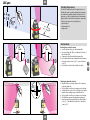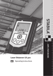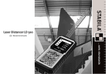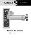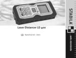
1
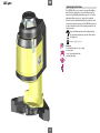
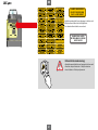
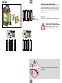
Operating Instructions
LAX 400
LAX 400
en
Operating Instructions
The STABILA-LAX 400 is an easy-to-operate self-levelling
multi-line laser, designed for use on building sites. The
laser unit is self-levelling within the range of ± 4°. The fine
adjustment allows precise 90° angles to be projected.
The laser lines are pulsed which makes it possible to work
over greater distances using a special STABILA line receiver.
For more information refer to the operating instructions for
the line receiver.
If you still have questions after reading through
the operating instructions, you can obtain advice
by telephone:
0049 / 63 46 / 3 09 - 0
Functions:
2 x vertical laser lines at a 90° angle
2 x cross lines
1 x 360° horizontal laser line
1 x plumb-line laser
1
en
LAX 400
LA SE R RA DI ATIO N
DO NOT STARE INTO BEAM
CLASS 2 LA SER PRODUC T
Attach the warning label in your language to the laser unit.
Affix the adhesive label over the English text.
LA SE R RA DI ATIO N
DO NO T ST AR E IN TO BE AM
LA SE R CL AS S 2
P0 < 1m W
The relevant adhesive labels are enclosed.
= 635n m
ビームをの ぞきこまないでと
レ ーザー クラス 2
RA DI ATIO N LA SE R
NE FIXER JAMAIS LE FAISCEAU
LA SER CLASSE 2
Before initial commissioning:
• Attach the warning label in your language to the laser unit
• Read the safety instructions -> Safety instructions
• Insert batteries -> Battery replacement
2
LAX 400
Safety instructions
en
Maintenance and upkeep
The STABILA laser measuring unit is an optical precision instrument and should therefore
be handled with care.
Before initial commissioning:
Window apertures, display windows:
Carefully read the safety instructions and operating instructions.
• Only permit qualified persons to operate the unit!
• Observe the safety precautions!
Dirty window glass impairs the optical function.
Only clean with a soft cloth, a little water or, if required, a mild detergent!
• Attach the warning label in your language to the laser unit. The relevant
Casing:
adhesive labels are enclosed. The positioning of the labels is described
in the operating instructions.
Clean the unit with a damp cloth.
•
•
•
Do not use solvents or thinners!
Do not immerse the unit in water
Do not unscrew the laser unit!
Transport and storage
• Remove the batteries if you do not intend to use the unit for
•
•
Warning:
Your eyes are normally protected by their lid closure reflex and / or a
natural instinct to turn away if you accidentally look into the laser
beam of class 2 laser units very briefly. If a laser beam hits your eye,
consciously close your eyes and move your head out of the path of the
beam. Do not look into the direct or reflected beam.
The STABILA laser goggles available with laser units are not protective goggles, rather
allow the laser light to be seen more easily.
•
•
•
•
Do not aim the laser beam directly at people!
•
•
•
Tampering (modifications) with the laser unit is not permitted.
•
•
•
some time!
Do not store the unit when damp!
Allow the unit and carry case to dry first if necessary.
Recycling programme for our EU customers
In accordance with WEEE rules, STABILA offers to dispose of electronic products
at the end of their useful service life.
For more information call: 0049 / 6346 / 309-0
Avoid dazzling other people!
Declaration of warranty by STABILA Laser
Keep out of the reach of children!
In addition to the statutory rights of buyers, which are not limited by this warranty,
STABILA guarantees that the unit is free from defects and has assured features in the
event of material or manufacturing defects for a period of 24 months from the date of
purchase. Any defects / errors will be remedied at our discretion through reworking
or replacement. STABILA will not assume liability for further claims. Defects resulting
from improper handling (e.g. damage due to application of serious force, operation
with incorrect voltage / current type, use of unsuitable power source) and unauthorised
modifications of the unit by the buyer or a third party shall invalidate the warranty.
STABILA does not provide a warranty for natural signs of wear and minor defects that do
not affect the operation of the unit. Any warranty claims should be made through your
dealer and be accompanied by your sales receipt, completed certificate of warranty (see
last page of operating instructions) and the unit itself.
It can result in dangerous exposure to radiation if operating and adjustment
equipment, or methods other than those described in these operating instructions,
are used.
The unit may malfunction if it is dropped or suffers serious vibrations!
Always check before you start work that the unit is functioning correctly and
accurately, especially if it has been exposed to heavy vibrations.
Do not use in explosive or corrosive environments!
Do not dispose of the batteries and unit with domestic waste!
Keep this user manual in a safe place and hand it over when passing the unit to
another person.
3
LAX 400
3
en
2
Components of the unit:
1. Laser casing
2. Fine adjustment
3. Casing frame
4. Height adjustment clamping lever
5. Magnet
6. Eyelets for attaching tensioning belt
7. Feet with bearing surfaces
8. 5/8" tripod socket
9. ON / OFF sliding switch with transport lock
10. ON / OFF button for marking laser
11. Button for selecting laser functions
12. Green LED:
Operating function
Yellow LED:
Battery charge indicator
13. Exit window for 360° laser line
14. Exit windows for vertical laser lines
15. Exit window for plumb-line laser
16. Battery compartment lid
5
13
6
1
4
14
15
7
11
10
9
360˚
360˚
360˚
8
360˚
12
6
7
8
5
4
16
LAX 400
en
Inserting / Replacing the battery
Open battery compartment lid (16) in the direction of the
arrow, insert new batteries as indicated by the symbol in
the battery compartment. Suitable rechargeable batteries
can also be used.
4 x 1.5 V
Alkaline
AA, LR6, Mignon
LED display:
Yellow LED (12): low battery charge - insert new battery
Dispose of used batteries at suitable
collection points - not with household waste.
Remove the batteries if you do not intend
to use the unit for some time!
Always use the centre of the laser line when marking
and aligning!
5
en
LAX 400
Commissioning with levelling function
Turn the laser casing to the working position. Use the
sliding switch (9) to switch on the laser unit. Horizontal and
vertical laser lines and the plumb-line laser dot appear.
The LED lights up green. The LAX 400 is in self-levelling
mode and levels itself automatically.
P0 < 1m W
= 635n m
The laser lines flash if the laser unit is at
too steep an angle.
The laser unit is outside the self-levelling
range and cannot level itself automatically.
> ±4°4°
6
> ±4°
en
LAX 400
P0 < 1m W
Selecting the laser functions
Once the unit has been switched on using the sliding
switch (9), use button (11) to switch between the various
laser functions.
= 635n m
1x
Levelling functions:
2 x vertical laser lines at a 90° angle
1 x 360° horizontal laser line
1 x plumb-line function
2x
3x
7
en
LAX 400
P0 < 1m W
P0 < 1m W
Plumb-line laser function:
The plumb-line dot will be clearly visible after the laser
casing has been pushed up and the feet spread apart (7).
This can be used to position the LAX 400 precisely.
Commissioning without levelling function
= 635n m
Only use the button (11) to switch on the LAX 400 in
Marking function mode. The horizontal and vertical
laser lines, plumb-line dot and LED flash quickly.
The LAX 400 is not in self-levelling mode and can
only be used in this mode for marking and alignment!
= 635n m
Marking functions:
2 x vertical laser lines at a 90° angle
1 x 360° laser line
1 x dot laser
5 sec
8
en
Additional functions
Function: Height adjustment
Use the clamping lever (4) to adjust the height of the laser
casing.
0
°
Function: Fine adjustment
Use the fine adjustment (2) to rotate the laser casing to
an exceptionally high degree of precision, which allows
the vertical lines to be precisely aligned.
9
LAX 400
9
en
LAX 400
Checking the accuracy
>2m
> 7 ft
90°
The LAX 400 multi-line laser is designed for use on
building sites and is perfectly adjusted before leaving
our premises. Regularly check the calibration of the
accuracy, as is the case with all precision instruments.
Always check the unit before starting work, especially
if it has been exposed to heavy vibrations.
• Vertical check
• Horizontal check
• Angle check
Y≈
Y ≈ 3 11 m
3 ft
11
256
”
11
256
1 mm
Vertical check
”
1 mm
II.
I.
Checking the 2 vertical laser lines
1. Create a reference line, e.g. with a plumb line.
2. Set up and align the LAX 400 at distance Y in front of
this reference line.
3. Compare the laser line with the reference line.
4. Do not allow the laser line to deviate from the reference
line by more than 1 mm ( 11/256” ) over a distance of
2 m (7’) !
5. Perform this check for both vertical laser lines.
Checking the plumb-line function
1. Align the LAX 400 precisely with one floor marking
using the plumb dot.
2. The projected laser line cross appears on the ceiling.
3. Turn the LAX 400 around 180° and align it once again
with the floor marking using the plumb-line dot.
4. The projected laser line cross appears on the ceiling.
5. The difference measured between the markings is
twice the actual discrepancy. With a ceiling height of
5 m ( 16’5” ), the difference should be no more than
3 mm ( 1/8” ).
D
10
I.
II.
en
LAX 400
Horizontal check
I.
II.
A
1
B
A
1
2
2
1
3
A
2
1
A
1
B
S = 5 m / 16’5”
B A
3
Checking the level of the horizontal laser line
2 parallel walls at a distance S of at least 5 m (16’5”)
apart are needed to carry out the horizontal check.
1. Position the LAX 400 as close as possible to wall A
on a horizontal surface.
2. Use an exit window for a vertical laser line to align
the LAX 400 with wall A.
3. Switch on the laser unit (sliding switch 9 )
4. Once automatic levelling has ended, mark the cross
projected onto wall A. Point 1.
5. Turn the LAX 400 around 180° and align with wall B
using the same vertical laser line exit window.
Do not adjust the height.
6. Once automatic levelling has ended, mark the cross
projected onto wall B. Point 2.
7. Now reposition the laser unit so that it is directly in
front of wall B. Align the LAX 400 with wall B using
the same exit window for a vertical laser line.
8. Move the laser line cross by turning and adjusting
the height until it precisely coincides with point 2.
9. Turn the LAX 400 round 180° and align with wall A
using the same vertical laser line exit window.
Do not adjust the height.
10. Move the laser line cross by turning the casing until it
precisely coincides with the marking line of point 1.
11. Once automatic levelling has ended, mark the cross
projected onto wall A. Point 3.
12. Measure the vertical distance between points 1 and 3.
Perform this check with both vertical laser lines!
Distance S to the wall
5m
10 m
15 m
16’5”
32’10”
49’3”
11
B
Maximum permissible distance:
3.0 mm
6.0 mm
9.0 mm
1/8”
1/4”
3/8”
I.
II.
en
LAX 400
Angle check
Checking the 90° angle
1. Mark point A on the floor at a distance of 10 m
(32’10”) in a sufficiently large corner of the
room.
2. Align the LAX 400 with point A using
the plumb-line dot.
3. Align the LAX 400 with the one wall using
a laser line.
4. Precisely mark point B on the floor at
the halfway point.
5. Precisely mark point C on the wall or floor.
6. Shift the LAX 400 and align with point B
using the plumb-line dot.
7. Align the LAX 400 with point C again using
the laser line.
8. Precisely mark point D on the other wall or
on the floor using the 90° laser line.
Note:
The distance from A to B, B to C and B to D
should be the same to guarantee accuracy.
9. Turn the LAX 400 through 90° and align
laser line 1 with point D.
10. Mark position E on the perpendicular 2nd
laser line as close as possible to point A.
11. Measure the distance between points A - E.
D
≥5
≥
C
B
≥5
≥
m
16’5”
m
≥5 m
16’5”
≥ 16’5”
10 m / 32’10”
A
C
C
D
B
A
B
A
A
E
D
C
C
D
B
E
A
12
A
A
Room length or
Maximum permissible
distance between distance between
points A and C
points A and E
10 m
20 m
3.0 mm
6.0 mm
32’10”
65’8”
1/8”
1/4”
LAX 400
en
Technical data
Laser type:
Red diode laser, pulsed line laser,
wave length 635 nm
Power output: < 1 mW, laser class 2 in accordance with IEC 60825-1:2007
This product compl. with the appl. requ. of 21CFR, parts 1040.10 and 1040.11.
Self-levelling range:
approx. ± 4°
Levelling precision*:
Horizontal laser line:
± 0.3 mm/m ± 3/8“ over 100ft centre of laser line
Laser line inclination: ± 0.2 mm/m ± 1/4” over 100ft laser line
90° precision:
± 0.3 mm/m ± 3/8“ over 100 ft
Vertical intersection:
± 0.3 mm/m ± 3/8“ over 100 ft
Plumb-line beam facing downwards: ± 0.3 mm/m ± 3/8“ over 100 ft
Batteries:
4 x 1.5 V alkaline, size Mignon, AA, LR6
Operating life:
approx. 10 hours (alkaline)
Operating temperature range: -10 °C to +50 °C / 14°F to +122°F
Storage temperature range:
-25 °C to +70 °C / -13°F to +158°F
Subject to technical modifications.
* when operated within the specified temperature range
Certificate of warranty for STABILA LAX 400
Customer:
Address:
Date of purchase:
Dealer (stamp, signature):
13
STABILA Messgeräte
Gustav Ullrich GmbH
STABILA Inc.
P.O. Box 13 40 / D-76851 Annweiler
Landauer Str. 45 / D-76855 Annweiler
332 Industrial Drive
South Elgin , IL 60177
Tel.: + 49 63 46 309 - 0
Fax: + 49 63 46 309 - 480
1.800.869.7460
e-mail: [email protected]
www.stabila.de
www.stabila.com