1
Beam Alignment System
“Compact”
User Manual
Manual Beam Alignment System Compact
version 6 – October 14, 2014
page 1 of 19
Contents
1. General.........................................................................................................................................3
2. System components.....................................................................................................................3
3. Specification................................................................................................................................4
3.1. Positioning accuracy........................................................................................................................6
4. Installation and operation.............................................................................................................7
4.1. Brief “step-by-step” instruction.......................................................................................................7
4.2. Introduction.....................................................................................................................................7
4.3. Set-up of optical components..........................................................................................................8
4.4. Inputs and outputs.........................................................................................................................10
4.5. Intensity adjustment......................................................................................................................10
4.6. Direction coding detector outputs.................................................................................................11
4.7. Optimization of laser beam position on detectors..........................................................................11
5. Operation and safety features.....................................................................................................12
5.1. Power level and position display...................................................................................................12
5.2. Variable intensity gain control......................................................................................................13
5.3. Low power switch-off...................................................................................................................13
5.4. Switch-on activity delay................................................................................................................13
5.5. Controller status signal..................................................................................................................13
5.6. Bandwidth limitation switch..........................................................................................................13
6. Optical components...................................................................................................................14
6.1. Steering mirror PKS......................................................................................................................14
6.2. Steering mirror PSH......................................................................................................................14
6.3. Detectors (4-quadrant diodes).......................................................................................................15
7. Drawings....................................................................................................................................16
7.1. Mirror mount PKS.........................................................................................................................16
7.2. Mirror mount PSH.........................................................................................................................16
7.3. Detector housing...........................................................................................................................17
8. Troubleshooting.........................................................................................................................17
8.1. No signals on display....................................................................................................................17
8.2. No signals on detector...................................................................................................................17
8.3. The laser beam is not correctly positioned....................................................................................17
8.4. The steering mirrors make exceptional noise................................................................................18
8.5. Laser position is not stable............................................................................................................18
9. Safety.........................................................................................................................................18
10. Check list for laser data...........................................................................................................19
10.1. Set-up data...................................................................................................................................19
10.2. Actuated mirrors..........................................................................................................................19
11. Contact.....................................................................................................................................19
Manual Beam Alignment System Compact
version 6 – October 14, 2014
page 2 of 19
1. General
The Compact laser beam stabilisation
compensates for vibrations, shocks, thermal
drift, or other undesired fluctuations of the
laser beam direction. The system should be
applied whenever laser fluctuations or
movements of optical components occur but
a high precision and stability of the beam
direction is required.
The desired position of the laser beam is
defined by a 4-quadrant-diode (4-QD) or a
PSD. For that purpose a small portion of
laser power transmitted through a highreflective deflection mirror is sufficient.
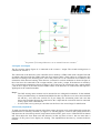
Figure 1: Principle of laser beam stabilisation
The closed-loop controller continuously
determines the deviation of the laser beam
from the desired position and drives the fast actuators in that way that the steering mirrors stabilise the
laser beam in the desired position.
The system is available in two different models. The 2-axes system comprises one detector and one
steering mirror and controls the laser beam in two axes. Thus, the laser beam is fixed in one position but
the beam direction can change. The 4-axes system combines two detectors and two steering mirrors in
order to detect the laser beam at two distant positions. Thereby both, position and direction are fixed.
2. System components
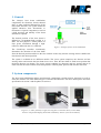
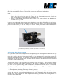
The laser beam stabilisation utilizes optoelectronic components (steering mirrors, detectors) as well as
electronic modules. We offer different types of actuators and detectors. For more details please check the
specification in section 3 and the photos in section 6.
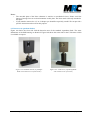
Figures 2, 3, and 4 (from left to right): Steering mirror with Piezo drive (version PSH),
detector with position display (horizontal orientation), detector (vertical orientation)
Manual Beam Alignment System Compact
version 6 – October 14, 2014
page 3 of 19
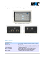
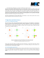
The system electronics (controller, amplifiers, power supplies) is fully integrated into a single compact
housing. It is powered by a standard 12V wall power supply.
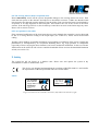
Figure 5: Keyboard and connectors on top panel
Figure 6: Power input and output connectors
on left side
Figure 7: Input connectors and switches
on right side
3. Specification
Optical parameters
Wavelength
Repetition rate
Laser beam diameter
Height of laser beam
Mirror diameter
Mirror thickness
Manual Beam Alignment System Compact
320 to 1100 nm, UV and IR detectors are available on request
any rate or cw
For repetition rates < 100 Hz we integrate an adaptation for low
repetition rates. For single pulses and operations with laser offtimes we offer an additional sample & hold circuit, see also note 1
< 6 mm (1/e²), see also note 2
45 mm for PKS actuators, 39.5 mm for PSH actuators
(Please ask for adapters if you need other heights.)
1" (standard), other beam diameters on request
1/4" or 1/8" (recommended)
version 6 – October 14, 2014
page 4 of 19
Controller housing dimensions
wxhxd
Steering mirror mounts
Type 1: PKS (K-700-31)
Actuator type
Bandwidth
Maximum tilt
Type 2: PSH (K-102-10)
Actuator type
Bandwidth
Maximum tilt
166 x 106 x 56 mm3
Piezo electric elements
< 700 Hz (measured with 1'' mirrors, thickness: 0.125'')
< 1 mrad (± 0.5 mrad)
Piezo electric elements
< 840 Hz (measured with 1'' mirrors, thickness: 0.125'')
< 2 mrad (± 1 mrad)
Position detector
Detector type
Bandwidth
Detection area
Mechanical dimensions
Optical filter
Si 4-quadrant diode (for standard wavelengths), see also note 3
< 10 kHz
10 x 10 mm² (for standard wavelengths), see also note 3
49 x 40 x 20 mm3
11.9 x 11.9 mm2
Control features
Power level display
Position display
Variable intensity gain
Low power switch-off
Switch on activity delay
LED bar with 10 elements on the backside of the detector unit
LED cross on the backside of the detector unit
Continuous, adjustable with potentiometer (1:6)
Power level falls below 10% of saturation power
300 ms
Connectors at controller unit
Actuator
Detector input
Controller status signal (Interlock)
x, y position output
Power supply
LEMO 0S series
LEMO 0B series
LEMO 00 series
LEMO 00 series
12 V / DC pin-and-socket connector
Connectors at detectors
x, y, intensity outputs
Power
MCX
12 V / DC pin-and-socket connector
Cable lengths
Detector → Controller (2 cables)
Actuator → Controller (2 cables)
Actuator → Controller (Elongation)
x-y-position cable (2 cables)
4 m (other lengths on request)
PKS: 1.5 m (directly mounted to Piezo element)
PSH: 1.2 m (directly mounted to Piezo element)
10 m (one pair of cables for one actuator is included in delivery,
additional or other cables on request)
2 m (other lengths on request)
Notes:
(1) A description of the sample & hold circuit is given in a separate appendix “Additional sample &
hold circuit to fix the laser beam position during laser-off times”.
(2) In case the beam diameter is larger than 6-8 mm, a lens in front of the detector can be used. For
larger beam diameters adapters for 1.5'', 2'' or other mirrors are available (on request, see also
figure 13b in section 6.2).
(3) UV and IR detectors are available on request. They may have differing dimensions and detection
areas. As an alternative to the 4-QDs we also offer PSDs. These can have different dimensions
and sensitive areas, too.
Manual Beam Alignment System Compact
version 6 – October 14, 2014
page 5 of 19
3.1. Positioning accuracy
The positioning accuracy depends on several parameters:
• Optical distance between steering mirror and detector: The accuracy is higher for larger distances.
Therefore a large distance should be chosen. The first steering mirror should be placed close to the
fluctuation source.
• Beam diameter: Having the same absolute change of laser beam position, a smaller diameter leads to
stronger power differences on the quadrants and therefore a steeper control signal. That is why laser
beams with smaller diameter can be positioned with higher accuracy.
• Intensity: The resolution of the detectors further depends on the intensity hitting the sensitive area.
This can be varied by an appropriate choice of optical filters and optimised electronically (see also
section 5.2).
• Repetition rate and pulse duration: The controller bandwidth can be optimised for different laser
parameters. Higher bandwidths lead to a faster reaction and therefore higher accuracy in case of fast
fluctuations.
In figure 8 the typical resolutions of the detectors are displayed. The example shows that a resolution of
better than 100 nm on the detectors can be achieved with an appropriate choice of parameters. The
angular resolution can be determined from these data with respect to the respective arm lengths.
Figure 8: Resolution of a 4-quadrant-diode irradiated by a red
He-Ne laser with different beam diameters and laser intensities
The actuators are controlled with an analog signal so that the positioning is not restricted in separate
steps. The positioning accuracy of the Piezo elements are specified as < 2nrad (PKS) and 4 nrad (PSH).
Manual Beam Alignment System Compact
version 6 – October 14, 2014
page 6 of 19
4. Installation and operation
4.1. Brief “step-by-step” instruction
The following steps shall assist you during the first startup of the beam stabilisation. The following
section will then explain the single steps more comprehensively.
1) Robust set-up of optical components (steering mirrors and detectors): The centres of the
detectors define the beam position. The detectors can be placed directly behind mirrors.
Alternatively, a small portion of the beam can be deflected to the detectors by means of a beam
splitter.
2) Cable connection: First mirror with output Actuator 1, second mirror with Actuator 2. First
detector with input 4QD1, second detector with input 4QD2.
3) Switch on power supply (switch on left side of housing): Thereupon the four green Range LEDs
will shine at the controller box.
4) Adjustment of intensity on detectors (by means of the potentiometer and if necessary exchange
of optical filters): In the best case 9 LEDs should be shining.
5) Pre-adjustment (with non-activated control stages): Adjustment of the laser beam onto the
detectors. After this step no red LEDs of the position display (LED cross) should shine.
6) Direction coding: Activation of control stage 1. If red LEDs are shining on the controller box the
switch position for x and y direction should be changed (see section 4.6).
7) Direction coding according to step 6, now for stage 2.
8) Fine-tuning for control stage 1: Deactivate both control stages ("Active" LEDs do not shine).
Then follow the description in section 4.7 until the x and y position outputs are close to 0V.
9) Fine-tuning for control stage 2: Activate stage 1 (stage 2 is still deactivated). Then proceed
according to section 4.7.
10) For the stabilised operation of 4 axes activate both stages.
4.2. Introduction
The system operation can be described best with reference to figures 5 to 7. The top panel in figure 5
shows the keyboard and the position signal outputs for two pairs of detectors and actuators (“stage 1”
and “stage 2”). Each stage can be switched on and off independently by pressing the Start/Stop button. If
the stage is started the small LED in the top right corner of the button is shining. The Range display
shows whether or not the steering mirrors are within the available capture range. The Active LED is
shining whenever the control stage is active. This is the case whenever the Start/Stop button has been
pressed and the laser power on the detectors has the right level.
The Position outputs on the top panel can be used to read out the current position of the laser beam on
each 4-quadrant diode (x and y).
Notes:
(1) Whenever the Start/Stop button is pressed (and the Active LED is on) the actuators start to move
from the zero position and then respond to the controller input.
(2) If a Range LED is shining red, this does not automatically mean that the beam is not stable. But
it indicates that no further tilt of the respective steering mirror is possible although it might be
necessary.
(3) If the power on the detectors is too low the actuators are driven to the zero position (and the
Active LED is off). This is due to the low power switch off that was implemented for safety
reasons (see section 5.3).
Manual Beam Alignment System Compact
version 6 – October 14, 2014
page 7 of 19
Figures 6 and 7 show both sides of the controller box with all input and output connectors and the
switches for the Directions and the Bandwidth selection. The cables going to the actuators are connected
on the left side. The cables coming from the 4-quadrant diodes are connected on the right side.
The direction switches enable a coding of the x and y directions of each controller stage. They are
connected with 4QD-1 and 4QD-2, respectively. The performance is further described in section 4. 6..
The function of the bandwidth limitation switch is explained in section 5.6.
The Status signal output can be used as an interlock or to drive a shutter (see section 5.5).
Note: The Piezo elements have large electrical capacity. That is why the cables should not be
disconnected as long as the Piezo elements are charged. I.e. you should always switch off the power of
the stabilisation system on the left side of the panel and then wait for a few seconds before you
disconnect the actuator cables.
4.3. Set-up of optical components
The optical components (steering mirrors and detectors) can be configured in variable arrangements for
different applications.
The detectors can be placed behind high-reflection mirrors. They are very sensitive and can work with
the leakage behind the mirrors. This has the advantage, that no additional components are required in the
beam path. Alternatively, it is possible to use the reflection of a glass plate or beam splitter in the beam
path. The latter can be necessary for lasers with larger beam sizes where the actuator would constrain the
transmission.
In any case, the centres of the 4-QDs are positioned in that way, that they define the desired laser beam
direction. The first actuator should be placed close to the laser or the last source of interference. The last
detector should be placed close to the target.
Note: Take care for a robust mechanical mounting of the optical components. If possible the delivered
components should be directly tightened to an optical table without further positioning equipment (like
height adjustment). If there are oscillating components with resonance frequencies within the control
bandwidth in the set-up, such resonances can provoke oscillations of the system at that frequency.
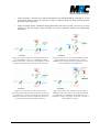
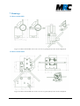
The following figures 9a-e show a selection of possible arrangements. These examples are demonstrated
with the 4-axes system with two 4QDs. However, they can be applied in similar configurations for the 2axes system with only one actuator and one detector.
•
Figure 9a shows a typical 4-axes set-up of the system where the laser beam hits the optical
components in the following sequence: steering mirror, combination of steering mirror and
detector, mirror with detector.
•
Figure 9b shows a similar set-up where additional lenses are placed in front of the detectors.
Further, a beam splitter is integrated in the beam path. This set-up might be better for lasers with
large beam diameters.
•
In figure 9c a lens is placed in front of detector 2 in order to improve the angular resolution. In
this case, the distance between lens and detector should be the focal length of the lens. The focal
length itself should be chosen in that way – depending on the beam diameter – that the focal spot
is not too small. The beam should still have a diameter on the sensor area of > 50 µm, so that it
hits all quadrants of the diode. (The gap between the quadrants of our standard 4QD measures
30 µm.)
Manual Beam Alignment System Compact
version 6 – October 14, 2014
page 8 of 19
•
Figure 9d shows a variation of 9c where both detectors are placed behind the same mirror. A lens
is placed in front of one of the detectors in order to measure both, the beam position and the
direction at the same point.
•
Figure 9e finally shows a different arrangement where the 4-axes system is used as two 2-axes
systems, i.e. the two stages of the controller are used to separately stabilise two independent
beam lines.
Figure 9a: Typical sequence of components for the 4axes stabilisation: Detector 1 stabilises the beam
position on actuator 2. Detector 2 then defines the beam
position at a separate point and hence the direction.
Figure 9b: Set-up as in 9a, with an additional beam
splitter and a lens in front of detector 1 and an
additional lens in front of detector 2 (Often used for
lasers with larger beam diameters)
Figure 9c: Set-up as in 9a, but a lens is used to
discriminate the angle by means of detector 2. This can
be of advantage in case of restricted space with small
distances between the optical components. Detector 2
must be placed in the focal plane of the lens.
Figure 9d: In this set-up both detectors are placed
behind the same mirror. Here, the beam position and
the direction are stabilised in close distance to the
application. Again, as in figure 9c detector 2 is used to
discriminate the angle.
Manual Beam Alignment System Compact
version 6 – October 14, 2014
page 9 of 19
Figure 9e: Set-up of a 4-axes system used as two 2-axes systems. With this set-up
the position of two independent lasers can be stabilised with one controller.
4.4. Inputs and outputs
The first steering mirror (figure 2) is connected to the Actuator 1 output. The second steering mirror is
connected to Actuator 2.
The connection of the detectors to the controller unit is made by a LEMO cable with a length of 4m and
an adapter cable that splits the LEMO cable into four separate cables. These cables are connected to the
detectors according to the following rules: The x and y lines have to be connected in accordance to the
orientation of the detector housing. If the detector is oriented in vertical orientation as shown in figure 4,
the x line has to be connected to the x output and the y line to the y output. If the detector is turned by
90° to a horizontal orientation as shown in figure 3, the x line has to be connected to the y output and the
y line to the x output. At the other end, the LEMO cables of the detectors are connected to the respective
4QD inputs at the controller module.
Notes:
•
•
The PKS steering mirror mounts can be mounted in two orthogonal orientations. In the standard
factory installation they are mounted and labelled in that way that the x axis drives the horizontal
tilt and the y axis drives the vertical tilt. If you change the orientation please take care that
always the horizontal tilt must be connected to the x input and the vertical tilt must be connected
to the y input of the controller box.
In case of the 2-axes system you can either use the first or the second stage for stabilisation.
4.5. Intensity adjustment
To make sure that the detectors operate in the linear range, the power level can be adjusted by tuning the
potentiometer for intensity variation (see figure 10). For that purpose, switch on the system (Power on)
and inactivate the closed-loop control (Stop button switched OFF, green Active-LED and LED on button
off). Then adjust the laser beam onto the detectors in that way that at least 3 but not more than 9
elements of the power level display are shining. The amplification increases by counter-clockwise
rotation.
Manual Beam Alignment System Compact
version 6 – October 14, 2014
page 10 of 19
If you do not find an appropriate adjustment you have to exchange the optical filters in front of the 4QDs. If the required filters are not available please contact the manufacturer or distributor.
Notes:
•
•
In a standard delivery we integrate two optical filters in front of the sensor area. These are a
filters with a high and a low density for coarse and fine adjustment, respectively. Usually the
filter which is the first to be reached is the low density one.
Please be aware that the sensor area is quite sensitive. If you want to clean it you should do this
carefully with a dry cloth.
If you want to exchange the filters you can detach the plastic screws which fix the filters in the housing.
With a tilt of the detector housing it should be possible to release the filters. Once you put in new filters
please be careful so that you do not damage the detector. Finally you can fix them with the plastic
screws.
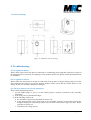
Figure 10: 4-quadrant-diode. The arrow points to the
potentiometer for intensity variation (Please use a screwdriver)
4.6. Direction coding detector outputs
For any deviation of the laser beam position on a 4-QD the respective steering mirror is tilted in that way
that it adjusts the laser beam back to the desired position. Each control stage makes use of a steering
mirror and a 4-QD as described in sections 4.2 and 4.3. The components that are working together are
identically coloured in figures 9. The direction in which the steering mirror must be tilted depends on the
arrangement of 4-QD and steering mirror. It can be changed during the pre-adjustment process described
in section 4.7 in the following way:
There are four switches on the right side of the controller module (see figure 7). These switches stand for
the x- and y- directions of the control stages Stage 1 and Stage 2. To turn them into the correct position
just switch on the respective stage. If the laser beam is then deflected into an extreme x (horizontal)
and/or y (vertical) position instead of the centre of the 4-QD, you have to toggle the belonging switch.
4.7. Optimization of laser beam position on detectors
i. Pre-adjustment (Obtaining linear range of steering mirrors)
Activate the controller module (Start button switched ON, green Active-LED and LED on button
shining) and adjust the laser beam onto the detectors by means of manually tilting the steering mirrors
until the four Range signals on the Piezo amplifiers are shining green. Now the steering mirrors are
operating in their linear range.
Manual Beam Alignment System Compact
version 6 – October 14, 2014
page 11 of 19
ii. Fine-adjustment (Obtaining zero position and full range of Piezo drives)
Inactivate the controller module (Piezo drives are in zero position, green Active-LEDs are dark) and
adjust the laser beam by means of manually tilting the steering mirrors in that way, that it hits the centres
of the 4-QDs. This can be done by reading out the x and y position outputs of the controller module or by
observing the position display on the backside of the detector module. The position outputs deliver a
signal that is directly proportional to the deviation from the desired position. You can easily display these
signals on an oscilloscope. The better the correlation of desired position and zero position, the smaller
the position shift after activating the closed-loop control.
After these adjustments the system should show no fluctuations of laser beam position after the last
mirror with detector when the controller is activated.
5. Operation and safety features
5.1. Power level and position display
The total power on each connected 4-QD (measured as the sum power on all quadrants) is displayed by
means of a LED bar on the backside of the detector module. Furthermore, a LED cross on the detector
module displays the current laser beam position. If the laser beam hits the centre of the 4-QD only the
green LED of the position display will shine. In other cases also yellow and red LEDs will shine
according to the examples in figure 11.
a)
c)
b)
d)
Figure 11: Examples for laser beams hitting the 4-QD (orange spots) and
the corresponding position display. The left pictures are shown in a view
from the rear side of the housing to the sensor area.
If only green and yellow LEDs are shining the sensor electronics is in the linear range where a direct
correlation between measured signal and position exists. If a red LED is shining too, the correlation is no
more possible due to the principle of 4-QDs.
5.2. Variable intensity gain control
For an easy adjustment of the signal intensity the stepless potentiometer on the side of the detector unit
can be used. This enables the optimization of the power level in case of intensity changes without an
exchange of optical filters. The gain can be changed by a factor of 6 between the lowest and the highest
value.
Manual Beam Alignment System Compact
version 6 – October 14, 2014
page 12 of 19
5.3. Low power switch-off
If the total power falls below 10% of the saturation power (and only one LED of the power level display
is on) the controller module automatically drives the mirrors into zero position. This leads to the
advantage that the closed-loop control can start from the zero position even if the laser was switched off
or blocked.
5.4. Switch-on activity delay
The integrated switch-on activity delay starts the controller module not before a short time has passed
and the steering mirrors have reached the zero position. The Active-LED will not shine during this delay.
5.5. Controller status signal
If the system is completely switched off (power-off), the Piezo actuators tilt the steering mirror into an
extreme position. This is about 0.5 mrad (PKS mount) or 1.0 mrad (PSH mount) from the zero position.
However, the system is equipped with a TTL output that can be used to block or electronically switch off
the laser in order to avoid damage by the misaligned beam. The level is HIGH whenever the controller
module is active and the steering mirrors are in the correct range or in zero position. It is LOW if the
module is active and one of the actuators is out of range. (If the controller module is not active, the level
is always HIGH.)
5.6. Bandwidth limitation switch
The controller bandwidth directly influences the quality of the stabilisation. The system can be operated
with two different controller bandwidths. The default setting is the high bandwidth. However, especially
in case of unstable mechanical set-ups or if a mutual interference of the control stages occurs it can be of
advantage to choose the low bandwidth. Therefore a bandwidth limitation switch is integrated in the
controller module (Bandwidth, see figure 7, H = high, L = low bandwidth). The bandwidth can be chosen
independently for both stages.
Note: The system uses the intensity centre of the transversal laser beam profile. It does not reduce
fluctuations of the laser beam profile itself.
Manual Beam Alignment System Compact
version 6 – October 14, 2014
page 13 of 19
6. Optical components
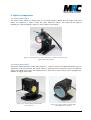
6.1. Steering mirror PKS
The mirror mount PKS has a tilting range of ± 0.5 mrad which is smaller then the range of the PSH
mount. In comparison, it offers a wider free space behind the mirror. The mount can be adjusted
manually for coarse adjustment. Figure 12 shows a photo of this mount.
Figure 12: Steering mirror mount PKS with 1'' mirror. The blue arrows
point to the x and y labels
6.2. Steering mirror PSH
The mirror mount PSH has a wider tilting range of ± 1 mrad. It can also be adjusted manually for preadjustment to the zero-position. The mirror mount is optimized for low torque by means of reinforced
springs and a balancing weight. The standard mount is used with 1'' mirrors. But it can be equipped with
adapters for bigger mirror sizes.
Figure 13a: Steering mirror mount PSH
with 1'' mirror
Manual Beam Alignment System Compact
Figure 13b: Steering mirror mount PSH
with adapter for 2'' mirrors
version 6 – October 14, 2014
page 14 of 19
Notes:
•
•
The movable plate of the Piezo elements is sensitive to mechanical forces. Please avoid the
impact of strong forces or torsional moments on this plate. The Piezo stack is directly attached to
this plate.
If you intend to remove the 1.5'' or 2'' adapter you should be especially careful. We can provide a
specific instruction and a tool for this purpose.
6.3. Detectors (4-quadrant diodes)
Figure 14a shows the front side with the detection area of the standard 4-quadrant diode. The outer
dimensions of the PSD housing are identical. Figure 14b shows the same side for the UV detector which
is available on request.
Figure 14a: Standard detector (4 quadrantdiode with sensitive area of 10x10 mm2)
Manual Beam Alignment System Compact
Figure 14b: UV detector (4 quadrant-diode
with sensitive area of 3x3 mm2)
version 6 – October 14, 2014
page 15 of 19
7. Drawings
7.1. Mirror mount PKS
Figure 15: Mirror mount PKS. For a better overview a typical path of a laser beam is displayed.
7.2. Mirror mount PSH
Figure 16: Mirror mount PSH. For a better overview a typical path of a laser beam is displayed.
Manual Beam Alignment System Compact
version 6 – October 14, 2014
page 16 of 19
7.3. Detector housing
Figure 17: Standard detector housing
8. Troubleshooting
8.1. No signals on display
Please check if the power line chord is connected to a conducting power plug and if the power switch at
the controller unit is activated. If everything is okay with the power line, please contact the manufacturer
or distributor.
8.2. No signals on detector
Please follow the instructions in section 4.5 and check if an aperture or edge is blocking the laser. If the
laser beam hits the sensitive area of the detector another reason can be that the chosen filters are too
strong. In that case the filters should be exchanged.
8.3. The laser beam is not correctly positioned
Please check the following issues:
i. Are all LEMO plugs (x and y) of each steering mirror correctly connected to the controller
electronics?
ii. Is the laser power in the allowed range?
iii. If the red Range-LED is on:
a. Are all cables connected as described in section 4.4?
b. Is the initial position of the laser beam in an acceptable position? If the initial position has
changed strongly the closed-loop control does not work in the linear range any more. Please
refer then to section 4.6.
c. Is the direction coding correct?
Manual Beam Alignment System Compact
version 6 – October 14, 2014
page 17 of 19
8.4. The steering mirrors make exceptional noise
Please immediately switch off the system. Irreparable damage to the steering mirrors can occur. Then
check the laser power on the detectors and adjust it as described in section 4. 5. Make sure that the initial
laser beam has not changed strongly and that it hits the 4-QDs. Take care that the beam is not blocked by
an aperture or an edge anywhere in the beam path. This could be the case at the cut-out of the Piezo
actuator. If the red Range-LED is on, the closed-loop control does not work in the linear range any more.
Please refer to section 4.5 then.
8.5. Laser position is not stable
If the automated stabilisation of the laser beam does not work although the controller is active this might
be due to a wrong direction coding of the 4-QD inputs (see section 4.6). Please check the direction
coding.
Another reason might be an unstable mechanical set-up leading to oscillations of the system. Usually this
phenomenon is accompanied by an exceptional humming noise. E.g. high positions of components
(especially of those carrying the Piezo elements) can lead to mechanical instabilities. In this case a better
stabilisation can be achieved with a lower controller bandwidth. Please activate the bandwidth limitation
switch (see section 5.6).
9. Safety
The system has left our factory in a faultless state. Please store and operate the system in dry
environments in order to maintain this state.
The device was designed and manufactured according to DIN EN 61000-3-2 and satisfies
the requirements of the European EMC Directive 89/336/EWG.
Labels
SN: 100208BA036
Model: 1kHz-CW
SN: 100208DBA036
Model: XY4QD 1kHz
Supply: 12VDC 0,2A
Supply: 12VDC 1A
MRC Systems GmbH
Germany
MRC Systems GmbH
Hans-Bunte-Str. 10
D-69123 Heidelberg
Germany
Figure 18: Labels on the controller electronics (left) and on the detectors (right)
Manual Beam Alignment System Compact
version 6 – October 14, 2014
page 18 of 19
10. Check list for laser data
For the final layout of the system and for an optimal support of your integration it can be helpful to know
your laser and set-up data. You can send us your data according to the following compilation:
customer
..............................................
wavelength / range
..............................................
average laser power
..............................................
pulse duration
..............................................
(fill in “cw” in case of a cw laser)
repetition rate
..............................................
(not applicable in case of a cw laser)
beam diameter
..............................................
beam profile
..............................................
(qualitative specs as “Gaussian”,
„elliptical”, etc. are sufficient)
10.1. Set-up data
If possible, please send us a drawing or a photo or your intended set-up. We can then give you
recommendations for the integration of the stabilisation system. We have our focus on an easy
arrangement of the optical components and on appropriate distances between actuators and detectors
(“arm lengths”) since they determine the reachable angular resolution.
10.2. Actuated mirrors
Please let us know if we shall provide the mirrors:
Who will provide the mirrors?
□ Customer
□ MRC (on request, on account)
The following mirror sizes are recommended:
•
standard: diameter 1'', thickness 1/4'' (1/8'' as an alternative)
•
on request: diameter 1.5'' and 2''
11. Contact
MRC Systems GmbH
Hans-Bunte-Strasse 10
D-69123 Heidelberg
Germany
Phone:
Fax:
Website:
E-mail:
06221/13803-00
06221/13803-01
www.mrc-systems.de
[email protected]
Manual Beam Alignment System Compact
version 6 – October 14, 2014
page 19 of 19