1
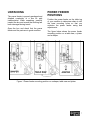
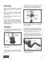
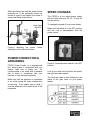
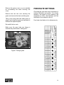
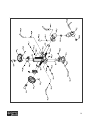
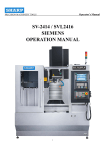
CXP02 1/4-HP FOUR SPEED POWER FEEDER User Manual TABLE OF CONTENTS General Safety Instructions for Machines ............................................................... 3 Specific Safety Instructions..................................................................................... 4 CXP02 Features ..................................................................................................... 5 Physical Features ................................................................................................... 6 Un-Packing ............................................................................................................. 7 Power Feeder Positions.......................................................................................... 7 Assembly ................................................................................................................ 8 Power Connection & Grounding.............................................................................. 9 Speed Changes ...................................................................................................... 9 Feed Rate Settings ................................................................................................. 10 Maintenance ........................................................................................................... 11 Roller Replacement ................................................................................................ 11 Lubricating the Rollers ............................................................................................ 11 Gear and Chains.....................................................................................................11 Gear Box................................................................................................................. 11 Cleaning.................................................................................................................. 11 Parts Breakdown and Parts List.......................................................................12 - 15 Warranty ................................................................................................................. 16 2 GENERAL SAFETY INSTRUCTIONS FOR MACHINES Extreme caution should be used when operating all power tools. Know your power tool, be familiar with its operation, read through the owner’s manual and practice safe usage procedures at all times. ALWAYS read and understand the user manual before operating the machine. NEVER leave a tool unattended while it is in operation. CONNECT your machine ONLY to the matched and specific power source. NEVER allow unsupervised or untrained person to operate the machine ALWAYS wear safety glasses respirators, hearing protection and safety shoes, when operating your machine. NEVER reach over the table when the tool is in operation. DO NOT wears loose clothing or jewelry when operating your machine. Wear protective hair covering. A SAFE ENVIRONMENT is important. Keep the area free of dust, dirt and other debris in the immediate vicinity of your machine. BE ALERT! DO NOT use prescription or other drugs that may affect your ability or judgment to safely use your machine. DISCONNECT the power source when changing drill bits, hollow chisels, router bits, shaper heads, blades, knives or making other adjustments or repairs. ALWAYS keep blades, knives and bits sharpened and properly aligned. ALL OPERATIONS MUST BE performed with the guards in place to ensure safety. ALWAYS use push sticks and feather boards to safely feed your work through the machine. ALWAYS make sure that any tools used for adjustments are removed before operating the machine. ALWAYS keep bystanders safely away while the machine is in operation. NEVER attempt to remove jammed cutoff pieces until the blade has come to a full stop. 3 CXP02 POWER FEEDER SPECIFIC SAFETY INSTRUCTIONS ALWAYS READ and understand the user manual before operating the power feeder. DO NOT FEED long work-pieces without providing proper support at the out-feed end of the table. MAKE SURE the cutting tools are rotating at the operating speed before feeding the work-piece into the cutter. ALWAYS STOP the feeder first, then the machine. NEVER OVERLOAD the cutting tool by feeding too quickly. The tool will perform better and be safer at the rate for which it is designed. KEEP YOUR FINGERS away from the rotating parts. Make sure hands and clothing are safely away from the rotating parts or the work-piece. MAKE SURE before making any adjustments, the switch is in the “OFF” position and the cord is un-plugged from the power source. BEFORE OPERATING your feed make sure you have read and understood all the safety instructions in the manual and you are familiar with your feeder. If you fail to do so, serious injury could occur. WARNING The safety instructions given above can not be complete because the environment in every shop is different. Always consider safety first as it applies to your individual working conditions. 4 CXP02 POWER FEEDER FEATURES MODEL CXP02 – 1/4-HP FOUR SPEED POWER FEEDER As part of the growing line of Craftex woodworking equipment, we are proud to offer the CXP02, A 1/4-HP Four Speed Power Feeder. The Craftex name guarantees Craft Excellence. By following the instructions and procedures laid out in this user manual, you will receive years of excellent service and satisfaction. The CXP02 is a professional tool and like all power tools, proper care and safety procedures should be adhered to. Motor ................................... 1/4-HP, 110-Volts, Single Phase, 60-Hz, 1720-RPM Power Transfer .................... Gear Box Number of Speeds............... Four Feed Speeds ....................... 20, 26, 33, 43 FPM Swing................................... 360-Degree Vertical Movement............... 6-3/4” Horizontal Movement........... 9-3/4” Feed Direction ..................... Forward and Reverse Number of Rollers................ 3 Roller Width ......................... 1-1/8” Roller Diameter.................... 3-1/16” Roller Construction .............. Synthetic Rubber Housing Construction .......... Cast Aluminum Column Construction ........... Steel Paint .................................... Powder Coated Paint Length/Width/Height ............ 34” x 13” x 24” Weight ................................. 75 lbs Warranty .............................. 3 Years 5 CXP02 1/4-HP POWER FEEDER PHYSICAL FEATURES Vertical Travel Crank Handle Elevating Bracket Horizontal Travel Lock Lever Upper Elbow Joint Lock Lever Horizontal Column 1/4-HP Motor Horizontal Travel Crank Handle Vertical Travel Lock Lever Vertical Column Rotary Movement Lock Lever Lower Elbow Joint Lock Lever Base 6 UNPACKING The power feeder is properly packaged and shipped completely in a box for safe transportation. When unpacking, carefully inspect the box and ensure that nothing has been damaged during transit. Open the box and check that the power feeder and the parts are in good condition. POWER FEEDER POSITIONS Position the power feeder on the table top of your machine to determine where to drill the base mounting holes so that you minimize the power feeder swing and adjustments. The figure below shows the power feeder mounting position on a table saw, a jointer and a shaper. Figure-1 Power feeder mounting position on a shaper, table saw and jointer 7 MOUNTING Place the power feeder base on the table surface where you want to mount the power feeder. Slide the elevating bracket with the horizontal column onto the vertical column as shown in figure-3 and tighten the levers. Mark the 4 holes on the table surface through the holes on the base using a center punch. Remove the base, drill and tap 4 holes on the table surface. Mount the base on the table surface using 4 sets of bolts and spring washers (not provided). Make sure the bolts are longer than the mounting base thickness plus the table top thickness. Figure-3 Horizontal column and elevating bracket assembly ASSEMBLY Insert the vertical column assembly into the base opening and tighten the lever as shown in figure-2. Now attach the column caps on the top of the vertical column and to the left end of the horizontal column and secure it using set screws (provided) as shown in figure-4. Install the crank handles assemblies on to the vertical and horizontal column caps and secure it using screws provided. See figure4. Figure-2 Vertical column secured into the base opening Now slide the horizontal column assembly into the elevating bracket as shown in figure-3. Figure-4 Installing the column cap and crank handle assembly 8 Slide the elbow joint with the power feeder assembly on to the horizontal column as shown in figure-5 and tighten the screw to secure the elbow to the column. SPEED CHANGES The CXP02 is a four speed power feeder and the feed rates are; 20, 26, 33 and 43 feet per minute. To change the speed of your power feeder: Make sure the switch is in the OFF position and the cord is disconnected from the power source. Figure-5 Attaching the power assembly to the horizontal column feeder POWER CONNECTION & GROUNDING CXP02 Power Feeder is a supplemental tool, which works in conjunction with your shaper, table saw or jointer etc... It’s recommended to be used with a machine that is wired in compliance with your national or local electrical regulation. Make sure that the appliance is connected to an outlet having the same configuration as the plug. If an adaptor plug is used, it must be attached to the metal screw of the receptacle. Figure-6 Forward/reverse switch in the OFF position Look at the feed rate list below and select the right feed rate required. The feed rate table is also attached to the inside of the gear cover on your power feeder. 9 Remove the gears cover on your machine by un-screwing the knob securing the cover. FEED RATE SETTINGS Remove the two hex nuts securing the gears and remove the chain and the gears. Choosing the right feed rate is important to achieve efficiency and quality. It is closely related to the speed of your machine, the sharpness of cutter, the hardness and the thickness of the material to be cut. Take a look at the feed rate table given on page-9 and install the gears as instructed to achieve the required speed. Feed rate chart below is for reference only. Re-install the hex nuts. Make sure the gear hubs are facing in towards the power feeder. See figure-7. Figure-7 Change gears 10 MAINTENANCE During the life of your tool, you will need to practice some regular maintenance to keep your feeder in peak performance condition. LUBRICATING THE ROLLERS Using a grease gun, apply a thin layer of grease after every 200 hours or 30 days into the fittings. WARNING When installing / removing and servicing any part of the machine, make sure the power switch is in the off position and the cord is disconnected from the power source. Failure to do so may result in serious personal injury or death. GEARS AND CHAINS Lubricate the gears and chains periodically with grease. GEAR BOX ROLLER REPLACEMENT Change the gear box oil after every 1000 hours or 6 months, if you are using your power feeder 8 hours every day. Turn the switch to OFF position and un-plug the cord from the power source. Remove the screws securing the rollers and replace the rollers with the new ones. Figure-9 Gear box oil fill port Figure-8 Removing the screws securing the roller Remember that, rotating the roller positions periodically will prolong the life of rollers. CLEANING Dust build up around the motor can decrease the life of the motor. Make sure the motor and the rollers remain free and clear of all dust and debris build up. 11 12 13 U010088 S600612 N050057 65B C020331 N950003 U010054 66B C020334A Roller Supporter A500336 N510022 S900625 K330018 68B A500331 N510026 69B G320018A Sprocket Shaft 39A-1 39A-2 39A-3 65B 65B-1 65B-2 65B-3 66B 66B-1 66B-2 66B-3 66B-4 67B 68B 68B-1 68B-2 69B 69B-1 N510015 39A 39A 69B-2 Q010015 21A-2 Snap Ring (15) Sprocket Shaft Kit (S) Snap Ring (26) Tube Tube Kit (S) Chain (18S) Cap Screw (M6-1.0Px25L) Snap Ring (22) Sprocket (13T) Roller Supporter(S) Case Cap Spring (φ30xφ3) Sprocket Case Sprocket Case Kit Lock Washer (1/4") Hex Screw (M6-1.0Px12) Brush Brush Kit (2 each) "O" Ring (P15) Oil Cap U010008 21A-1 Oil-Cap Kit Description 21A Code # 21A Part # 1 2 3 3 3 3 2 1 1 1 1 2 1 1 1 1 1 1 2 2 1 1 1 Q'ty Frame Kit (32) Frame (32) Bushing (29Dx23Dx(7+3)) Back Cover (AF32) Transmission Kit Sprocket Double Sprocket Bushing Chain (30S) Chain (22S) Worm Gear Kit 60Hz Wormgear Spindle 60Hz Flat Washer (3/8"x25D) N11010R 71B T315106 G320067 N030008 N11008R 75B C020321 A500306 U010031 77B A500303 A500307 A500308 K330030 K330022 79B G320016 N015925 70B-3 71B 71B-1 71B-2 71B-3 71B-4 79B-2 79B-1 79B 77B-5 77B-4 77B-3 77B-2 77B-1 77B 76B 75B-2 75B-1 75B Nut (M8-1.25P) N015925 70B-2 Spring Washer (8.3x1.8t) Sprocket Shaft Grease Nipple (M6-1.0Px1.0) Roller Spindle Kit (S) Nut (M10-1.5P) Flat Washer (3/8"x25D) G320017A Sprocket Shaft 70B-1 Sprocket Shaft Kit (S) Description 70B Code # 70B Part # 1 1 1 1 3 1 1 1 1 1 1 1 2 2 1 1 1 1 1 1 1 1 Q'ty U010051 J120007 86B 85M3 85M1 85B3 85B1 Q010060 A500326 A500323 82B A500324 A500327 81B S900512 Q021701 C020322 A500302 U210007 80B N11010R Code # RO081 C020302 97A 87B 86B 85M3 85M1 85B3 85B1 83B 82B-2 82B-1 82B 81B-2 81B-1 81B 80B-5 80B-4 80B-3 80B-2 80B-1 80B 79B-3 Part # Roller (φ80x30mm) Knob (M6-1.0Px30L) Switch Switch Box Kit (S) Motor/Switch (1/4HP, 3Ph) Motor/Switch (1/4HP, 1Ph) Motor Kit (1/4HP, 3Ph) Motor Kit (1/4HP, 1Ph) "O" Ring (G60) Gear (24T) Gear (26T) Gear Kit 24T/26T(S) Gear (20T) Gear (30T) Gear Kit 20T/30T(S) Cap Screw (M5-0.8Px12L) Oil Seal (17x32x7t) Wormgear Cover Bushing (29Dx23Dx(15+3)) Oil Seal Wormgear Cover Kit Nut (M10-1.5P) Description 1 1 1 1 1 1 1 1 1 1 3 1 1 1 1 1 4 1 1 1 1 1 Q'ty 14 15 WARRANTY CRAFTEX 3 YEARS LIMITED WARRANTY Craftex warrants every product to be free from defects in materials and agrees to correct such defects where applicable. This warranty covers three years for parts and 90 days for labor (unless specified otherwise), to the original purchaser from the date of purchase but does not apply to malfunctions arising directly or indirectly from misuse, abuse, improper installation or assembly, negligence, accidents, repairs or alterations or lack of maintenance. Proof of purchase is necessary. All warranty claims are subject to inspection of such products or part thereof and Craftex reserves the right to inspect any returned item before a refund or replacement may be issued. This warranty shall not apply to consumable products such as blades, bits, belts, cutters, chisels, punches etceteras. Craftex shall in no event be liable for injuries, accidental or otherwise, death to persons or damage to property or for incidental contingent, special or consequential damages arising from the use of our products. RETURNS, REPAIRS AND REPLACEMENTS To return, repair, or replace a Craftex product, you must visit the appropriate Busy Bee Tools showroom or call 1-800-461-BUSY. Craftex is a brand of equipment that is exclusive to Busy Bee Tools. For replacement parts directly from Busy Bee Tools, for this machine, please call 1-800-461-BUSY (2879), and have your credit card and part number handy. All returned merchandise will be subject to a minimum charge of 15% for re-stocking and handling with the following qualifications. Returns must be pre-authorized by us in writing. We do not accept collect shipments. Items returned for warranty purposes must be insured and shipped pre-paid to the nearest warehouse Returns must be accompanied with a copy of your original invoice as proof of purchase. Returns must be in an un-used condition and shipped in their original packaging a letter explaining your reason for the return. Incurred shipping and handling charges are not refundable. Busy Bee will repair or replace the item at our discretion and subject to our inspection. Repaired or replaced items will be returned to you pre-paid by our choice of carriers. Busy Bee reserves the right to refuse reimbursement or repairs or replacement if a third party without our prior authorization has carried out repairs to the item. Repairs made by Busy Bee are warranted for 30 days on parts and labour. Any unforeseen repair charges will be reported to you for acceptance prior to making the repairs. The Busy Bee Parts & Service Departments are fully equipped to do repairs on all products purchased from us with the exception of some products that require the return to their authorized repair depots. A Busy Bee representative will provide you with the necessary information to have this done. For faster service it is advisable to contact the nearest Busy Bee location for parts availability prior to bringing your product in for repairs. 16