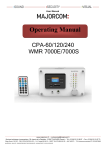
1
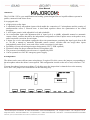
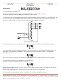
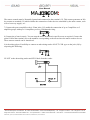
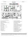
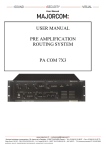
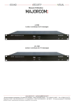
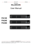
User Manual USER MANUAL PRE-AMPLIFICATION ROUTING SYSTEM PA COM 13X5 www.majorcom.fr • [email protected] Services techniques et commerciaux : 56, chemin de la Flambère - 31300 TOULOUSE (France) • Tel. +33 (0)5 61 31 86 87 • Fax. +33 (0)5 61 31 87 73 Siège Social : RN 307 - 78810 FEUCHEROLLES • S.A. Capital 80.000 € • SIRET 334 579 869 000 28 • NAF 4652 Z • TVA Intracommunautaire FR 12334579869 MAJORCOM \ QUALITE \ ENREGISTREMENT DES DOCUMENTS \ ADMINISTRATIF \ ENR-12-PEM-V02 User Manual I Functions The PA COM 13X5 is a pre-amplification and routing system designed for use in public address systems in public, commercial and leisure areas. It is equipped with: a high priority safety input 5 adjustable priority microphone inputs which enable the connection of 5 microphones and the routing of announcements across 5 selected areas. A dual band equaliser allows the optimisation of the sound broadcast. 2 AUX inputs (music) with adjustable level and switchable. An event/podium input with adjustment dial of input level (0 to 60dB), adjustable manual or automatic remote control, switches that allow the independent configuration of these inputs across each speaker areas, and a bass/treble correction for each input 2 inputs for wireless microphone equipped with a trim potentiometer permitting the input’s gain from 0 dB to –60 dB, a manual or automatic adjustable remote control, switches that can assign these inputs independently on the first 3 areas, and a bass / treble correction for each input. Possibility to insert advertising messages during music (LECT. PUB. optional) Electronic chime for the pre-announcement of microphone calls The presence of modulation on each source is signalled by LED. Can be operated on a 24V DC emergency power supply. II Configuration The chime can be removed from some microphones, if required. For this, remove the jumpers corresponding to the microphone where the chime is not required. This configuration is made on the micro card, reference CI 02 7. You can also choose between two chimes. To do this, move the jumper that is situated close to the memory M27C4001. The jumpers are tracked down in the following way: www.majorcom.fr • [email protected] Services techniques et commerciaux : 56, chemin de la Flambère - 31300 TOULOUSE (France) • Tel. +33 (0)5 61 31 86 87 • Fax. +33 (0)5 61 31 87 73 Siège Social : RN 307 - 78810 FEUCHEROLLES • S.A. Capital 80.000 € • SIRET 334 579 869 000 28 • NAF 4652 Z • TVA Intracommunautaire FR 12334579869 MAJORCOM \ QUALITE \ ENREGISTREMENT DES DOCUMENTS \ ADMINISTRATIF \ ENR-12-PEM-V02 User Manual III Connections 1) Connect the power supply (21). 2) Connect the 24V DC safety supply on terminals (29). The + to red and the - to black. The device should be turned on during the connection of the batteries. 3) Connect the sub-d 25 point plug coming from a desk microphone (such as MAGPX 5) to the input (20). The use of a 6/10, 5 pair phone shielded cable is advised. If the use of another type of microphone is required connect the diodes on the areas where this microphone should broadcast, as follows: 4) Connect the music sources: CD, tape, radio, and the event podium AUX on a 6.35mm jack as follows: An event podium can make a balanced connection on the rear panel (19) for permanent installation or on the front panel (1) for temporary installation. The connection of a plug in the front socket (1) automatically disconnects the rear. This source must be equipped with a balanced output. If not, a 600 / 600 transformer will be required. 5) Connection of wireless event podium to 6.35 mm jack (22): This input is balanced and must be wired as follows: If your wireless system supplies a remote control by dry contact, link this remote to the terminal (26) and put switch (27) to Ext. Rem. There are two independent H.F. inputs. Proceed in the same way for the second input. 6) Connect the emergency player to the 6.35 mm jack (31) as follows (unbalanced input): www.majorcom.fr • [email protected] Services techniques et commerciaux : 56, chemin de la Flambère - 31300 TOULOUSE (France) • Tel. +33 (0)5 61 31 86 87 • Fax. +33 (0)5 61 31 87 73 Siège Social : RN 307 - 78810 FEUCHEROLLES • S.A. Capital 80.000 € • SIRET 334 579 869 000 28 • NAF 4652 Z • TVA Intracommunautaire FR 12334579869 MAJORCOM \ QUALITE \ ENREGISTREMENT DES DOCUMENTS \ ADMINISTRATIF \ ENR-12-PEM-V02 User Manual The remote control must be Normally Opened and connected to the terminal (33). This remote generates an NO dry contact on terminal (32) which enables the connection of other devices controlled by the same contact, such as level recovery supply, etc... 7) Connect the power amplifiers: the 6.35mm jacks (35) enable the connection of up to 5 amplifiers or 5 amplifier groups with up to 10 amplifiers per area. Unbalanced wiring. 8) Connection of cuts in music. You can stop the music broadcast in specific areas as required. Connect the point COM of the terminal (36) to the numbers corresponding to the areas where the music needs to be cut. These remote controls can be transferred. 9) Advertising player: Possibility to connect an advertising reader of LECT. PUB. type on the jack (34) by respecting the following: LF OUT to the advertising reader and LF IN back from the reader. www.majorcom.fr • [email protected] Services techniques et commerciaux : 56, chemin de la Flambère - 31300 TOULOUSE (France) • Tel. +33 (0)5 61 31 86 87 • Fax. +33 (0)5 61 31 87 73 Siège Social : RN 307 - 78810 FEUCHEROLLES • S.A. Capital 80.000 € • SIRET 334 579 869 000 28 • NAF 4652 Z • TVA Intracommunautaire FR 12334579869 MAJORCOM \ QUALITE \ ENREGISTREMENT DES DOCUMENTS \ ADMINISTRATIF \ ENR-12-PEM-V02 User Manual IV Operation Before turning the power on, ensure that the connection recommendations described above have been followed, and that the amplifier levels and input/output level potentiometers have been set to zero. The PA COM 13X5 can now be switched on and the 24V battery connected if needed (Displayed by POWER LED (7) on front panel). The amplifiers and sources can also be turned on. Gradually turn up the amplifier volumes to ¾ of their range. Gradually turn up the volume of the 5 area outputs (35) to ¾ of their range. 1) Music Sources: Adjust the master level (4) to 50% and bass and treble to the middle. Once the sources are connected and operating correctly, gradually increase the potentiometer (19) of the source selected using the switches (3) on the front panel until the desired listening level is reached (Selection is displayed by an LED). Adjust the source tone with the trim potentiometer (5). 2) Microphone Decks: Select a broadcast area on the first desk. Press and hold the call button. The busy LEDs on all the microphones are lit. The music is cut in the selected areas. The chime starts (unless it was configured not to be used). Adjust the chime level with the trim potentiometer (16). Adjust the microphone level as required during message broadcast by turning the potentiometer (14). Adjust the tone with the trim potentiometers (15). Release the call button: the music is back. 3) H.F. 1 (resp. 2) Event Podium: The receiver is turned on and connected to the socket (22): Adjust the input level according to the receiver with the trim potentiometer (23) (receiver output 0 dB or - 60 dB). Choose the broadcast areas for event 1 with the switches (8) If the receiver has a squelch command with Normally Opened dry contact connected to the socket (26), configure in “ext rem” on the button (27) Otherwise, configure the automatic remote control (27) to “int rem”. The message detection is set by the level sensitivity (24) and the recovery time (25). Adjust the level with the potentiometer (9). The modulation is displayed on an LED « signal » above this potentiometer (9) (resp. 12) in addition to the remote. Adjust the tone with the trim potentiometer (10) (resp 13). 4) Emergency Message Reader: When the emergency reader (LN4M for example) is correctly connected to the socket (31), the operation is started by a dry contact (NO) on the terminal "SECURITY REMOTE" "TEL IN" (33). The safety reader has the highest priority over all other modulation and is broadcast in a general call. Adjust the level with the trim potentiometer (17). A red LED displays the broadcast of the emergency message. 5) Adjusting the Output level: Each area can be independently adjusted with the trim potentiometers (35). This allows level adjustment according to each area. www.majorcom.fr • [email protected] Services techniques et commerciaux : 56, chemin de la Flambère - 31300 TOULOUSE (France) • Tel. +33 (0)5 61 31 86 87 • Fax. +33 (0)5 61 31 87 73 Siège Social : RN 307 - 78810 FEUCHEROLLES • S.A. Capital 80.000 € • SIRET 334 579 869 000 28 • NAF 4652 Z • TVA Intracommunautaire FR 12334579869 MAJORCOM \ QUALITE \ ENREGISTREMENT DES DOCUMENTS \ ADMINISTRATIF \ ENR-12-PEM-V02 User Manual V Technical Characteristics Inputs: Music Inputs: 4 X 0 dB unbalanced 10 k inputs. Event/Podium: 1 600 balanced on jack in front and rear panel. Wireless Event/Podium: 2 x balanced -60/0 dB inputs - equipped with external or automatic remote control Area selection - Priority over music. Microphone Input: 5 x balanced inputs - priorities between microphones - microphones have priority over music and events Tone control: 3 x 2 band equalisers 100 Hz and 8 kHz (10 dB) Integrated chime: Digital chime automatically started during microphone call. Emergency reader input: unbalanced 0 dB with remote control – Absolute Priority – LED display. Insertion of an advertising reader during music with the “LECT. PUB.” (optional). Outputs: 5 X unbalanced outputs 0 dB with independent level adjustment Each output can supply up to 10 power amplifiers. Power supply: 230V 50 Hz or 24V DC. Dimensions: 483 x 430 x 132 (mm) 19" 3U Weight: 7 kg. www.majorcom.fr • [email protected] Services techniques et commerciaux : 56, chemin de la Flambère - 31300 TOULOUSE (France) • Tel. +33 (0)5 61 31 86 87 • Fax. +33 (0)5 61 31 87 73 Siège Social : RN 307 - 78810 FEUCHEROLLES • S.A. Capital 80.000 € • SIRET 334 579 869 000 28 • NAF 4652 Z • TVA Intracommunautaire FR 12334579869 MAJORCOM \ QUALITE \ ENREGISTREMENT DES DOCUMENTS \ ADMINISTRATIF \ ENR-12-PEM-V02 User Manual VI Device Presentation Front panel Rear panel 1: Event podium balanced 600 jack 2: Event podium level 3: Music source selection 4: Music level and modulation display 5: Music tone 6: On/off switch 7: Power on display 8: Area selection for Event 1 9: Event 1 level 10: Event 1 tone 11: Area selection for Event 2 12: Event 2 level 13: Event 2 tone 14: Micro 1 to 5 level 15: Micros tone 16: Chime level 17: Emergency level 18: Security On/off switch 19: Music sources inputs and adjusts 20: Microphone desks inputs 21: Power inlet 230V 50 Hz 22: Event 1 input 23: Input level adjust 24: Remote control sensitivity adjust 25: Remote control delay adjust 26: External remote control terminal 27: Remote control type selection 28: DC supply fuse 29: 24V DC supply terminal 30: Processor reset button 31: Security input 32: Security remote control output 33: Security remote control input 34: Advertising insertion jack 35: Output jack and level adjust 36: Music cut terminal www.majorcom.fr • [email protected] Services techniques et commerciaux : 56, chemin de la Flambère - 31300 TOULOUSE (France) • Tel. +33 (0)5 61 31 86 87 • Fax. +33 (0)5 61 31 87 73 Siège Social : RN 307 - 78810 FEUCHEROLLES • S.A. Capital 80.000 € • SIRET 334 579 869 000 28 • NAF 4652 Z • TVA Intracommunautaire FR 12334579869 MAJORCOM \ QUALITE \ ENREGISTREMENT DES DOCUMENTS \ ADMINISTRATIF \ ENR-12-PEM-V02