1
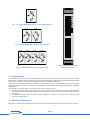
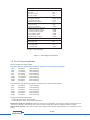
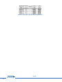
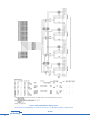
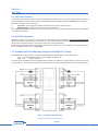
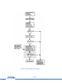
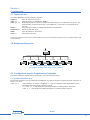
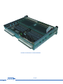
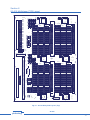
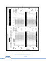
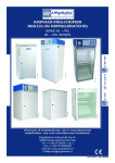
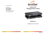
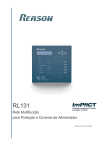
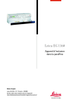
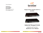
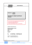
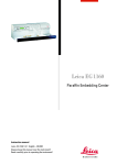
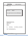
USER MANUAL
pickering
Model No.
20-610
Very High Density Universal Multiplexer
Designed & Manufactured by:Pickering Interfaces Limited.
Stephenson Road
Clacton-on-Sea
Essex
CO15 4NL
England
Tel:
Fax:
01255-428141
01255-425349
+44 1255-428141 (International)
+44 1255-425349 (International)
Internet: www.pickeringswitch.com
E Mail: [email protected]
Issue 2 7/02
© Copyright (2002) Pickering Interfaces Ltd. All Rights Reserved
pickering
20-610
VERY HIGH DENSITY UNIVERSAL MULTIPLEXER
1
HELP!!!
If you need assistance with your Pickering Interfaces Switching System:
Switching problems, Programming or Integration within your Test System.
– Please ring Pickering Interfaces and ask for “Technical Support”.
Alternatively you may fax, email or connect to our Internet Web Site.
A full set of operating manuals, application notes and software drivers is
available on CD ROM.
2
pickering
20-610
VERY HIGH DENSITY UNIVERSAL MULTIPLEXER
Contents
Section 1
Very High Density Universal Multiplexer .....................................................................5
Section 2
20-610 Operating Configurations and Expansion .......................................................9
Section 3
Self Test ....................................................................................................................13
Section 4
Programming ............................................................................................................15
Section 5
Connector Pin-Out Diagrams....................................................................................19
Section 6
20-610 Multiplexer PCB Layout ................................................................................37
pickering
20-610
VERY HIGH DENSITY UNIVERSAL MULTIPLEXER
3
4
pickering
20-610
VERY HIGH DENSITY UNIVERSAL MULTIPLEXER
Section 1
Very High Density Universal Multiplexer
1.1 Features
• Very High Density 352 Pin Multiplexer
• Single, Dual or Quad Multiplexer Operation, Switching 1, 2, 4 or 8 Poles
• Expandable to 10,000 Channels Using Internal Analogue Bus
• Automatic Isolation Switches Reduce Capacitive Loading in Large Systems
• High Quality Ruthenium Reed Relays For Maximum Reliability
• Built-In Self Test
• Suitable for Ribbon Cable Connection
• Versatile Configuration Options: “One Module for ALL Your General Purpose Multiplexer Applications”
• Lower Density 176 Pin Version Available
The Universal Very High Density Multiplexer, Model 20-610, offers the highest density of any Pickering
Multiplexer, with 352 switch pins. Configurable as a single, dual or quad multiplexer with a choice of 1, 2,
4 or 8 pole switching and is expandable to over 10,000 channels.
1.1 Description
The 20-610 Universal 352 Pin Multiplexer Module is the first in a new generation of very high density multiplexers from
Pickering Interfaces. One standard module offers a very large range of switching configurations plus extensive built
in self-test.
The 20-610 may be easily configured for most general purpose multiplexer requirements. Just by setting on-board
links the unit may be configured as a single, dual or quad multiplexer with a choice of 1, 2, 4 or 8 pole operation (total
of 18 configurations). The analogue common/s may be routed to the front panel or, for large system implementation,
to one of the internal analogue buses. This versatility means that one multiplexer module is suitable for many different
applications.
For applications that require lower capacity a reduced density version, type 20-610-021, is available, this has 176
pins.
Up to 2816 input channels can be accommodated in one System 20 Case, over 10,000 with multiple expansion
cases.
Built-in Automatic Isolation Switching connects only the currently active multiplexer switch bank, thereby keeping
capacitive loading and leakage currents in large multiplexer systems to a minimum.
For a summary of switching capabilities please refer to table 1.1.
This is a double height module and must be mounted into a double height (6U) case.
1.2 Front Panel
The module front panels comprise of three elements:
Status Display, 4 LED Indicators:Power LED.
Connected to power system supply.
Active LED.
On whenever one or more matrix switches are closed. For a list of all active switches use the
VIEW? command.
Warning LED.
Indicates that an error may be soon be failing (relay contacts reaching end of life).
Self-Test LED.
Active when self-test in progress.
Error LED.
Indicates that error found during self-test.
Serial (RS-232) Configuration/Test Port
The 20-610 has a built in RS-232 port (9600 baud software handshake), this is used to configure the module and may
also used for self test and error diagnosis (this may also be done using the normal IEEE-488/RS-232 interface).
Connectors - suitable for ribbon cable connection
Connection to the module front panel is via four 96 way DIN41612 connector plugs. Because of the large number of connections that may to be made to this module (up to 384) care must be taken with user connections. IDC type DIN41612
connectors may be used. Other connector types may be available, please contact sales office for further information.
pickering
20-610
VERY HIGH DENSITY UNIVERSAL MULTIPLEXER
5
1
2
3
4
1
Common
POW
2
3
351
ACT
352
4
TEST
1
Common
2
Bank 1
WARN
Bank 2
Fig .1.1 Single MUX
Mode: 44, 88, 176 or 352 Channels
3
351
1
1
352
4
2
3
Bank 1
Common 2
4
4
1
2
352
2
3
3
175
Common 2
176
Bank 1
4Bank
Common 1
1
2
175
176
4
1
Bank 1
2
2
Bank 2
175
3
Bank 3
Bank 4
175
3
1
176Common 2
2
4
Common 1
3
Bank 2
1
Common
1
351
1
176
1
Bank
4 2
1
2
2
4
3
Bank 1
2
3
3
Bank
4 3
Bank4 4
3
Commo
n4
Fig 1.2 Dual MUX Mode: 44, 88 or 176 Channels
1751
Commo
n1
87
3
Commo
n2
1
2
176
2
176
88
87
87
2
3
87
2
3
4
Commo
n1
Commo
n2
1
87
2
88
3
Commo
n4
4
4
Commo
n3
88
87
87
87
87
88
4
88
3
4
88
Bank 4
1
88
87
3
Commo
88
n4
4
Bank Commo
3n 3
1
88
2
87
3
88
4
1
2
87
3
4
Bank 2Commo
n2
1
Commo
n3
1
175
4
Bank 1 Commo
n1
2
ERR
2
Common
88
88
Fig 1.3 Quad MUX Mode: 44 or 88 Channels
Fig 1.4 20-610 Front Panel
Module Illustration
1.3 Analogue Bus
The analogue common can be routed (using internal jumpers) out to either the front panel connectors or the internal
analogue bus. Routing to the front panel allows the user complete flexibility, routing to the internal analogue bus simplifies
large system construction and ensures good signal isolation from external interference.
The System 10/20 backplane features a shielded 24 pole analogue bus. This would be used with a multiplexer
constructed using more than one module where the selected channel will be carried along the System 20 backplane
analogue bus.
The analogue bus can be brought out from the module in any of the following ways:1. The selected analogue common can be brought out on the front panel input connector. This also has the additional feature
of keeping the analogue signal totally isolated from the backplane, improving crosstalk, dc leakage and low thermal emf
performance.
2. Via a Breadboard module. Very useful if any signal conditioning, boosting etc. is to be done before bringing the signal
out to the measuring device.
1.4 Width and Dimensions
All modules conform to the 6U height (262mm) Eurocard standard and are 160mm deep. Panel width is 1.8 Inches.
6
pickering
20-610
VERY HIGH DENSITY UNIVERSAL MULTIPLEXER
Switch Type
Ruthenium Reed
Max Standoff Voltage
Max Power
Max Switch Current
Max Carry Current
100V
10W
0.5A
1.2A
Path Resistance
On (Single Module):
Off (Single Module):
Differential Thermal Offset
500mΩ (typical)
> 109 Ω
< 5µV
Capacitance
Open Channel
Channel to Channel
Crosstalk (Single Chan On, 50Ω)
Channel to Channel 10kHz
Channel to Channel 100kHz
Channel to Channel 1MHz
Bank to Bank 100kHz
Bank to Bank 1MHz
Bandwidth (3dB, 1 module)
> 80dB
> 65dB
> 45dB
> 80dB
> 65dB
> 5MHz
Noise Level (0 to 1MHz in 50Ω System)
< - 80dBm
Max Operate Time
Max Release Time
Expected Life (Operations)
Low power load
Full power load
7ms
6ms
< 6pF
< 30pF
> 108
> 5x10⁶
† All the above specifications are for a complete 20-610 system
consisting of eight multiplexers.
Table 1.1 Switching Specification
1.5 20-610 Operating Modes
Refer to Section 2 for further details.
The 20-610-022 very high density multiplexer operates in all of the following modes:Quad
Quad
Dual
Dual
Dual
88 Channel
44 Channel
176 Channel
88 Channel
44 Channel
1 Pole Switching
2 Pole Switching
1 Pole Switching
2 Pole Switching
4 Pole Switching
Single
Single
Single
Single
352 Channel
176 Channel
88 Channel
44 Channel
1 Pole Switching
2 Pole Switching
4 Pole Switching
8 Pole Switching
The 20-610-021 high density multiplexer operates in all of the following modes:Quad
44 Channel
1 Pole Switching
Dual
Dual
88 Channel
44 Channel
1 Pole Switching
2 Pole Switching
Single
Single
Single
176 Channel
88 Channel
44 Channel
1 Pole Switching
2 Pole Switching
4 Pole Switching
Analogue Common Connections
Route Analogue Common to Front Panel
Route Analogue Common to Internal Analogue Buses
Expansion to multi case systems is achieved by choosing one module within each case and selecting the analogue bus to
front panel configuration, the analogue bus commons are then simply daisy-chained to additional cases as required.
Multi channel selection: Care must be taken when selecting many channels simultaneously not to overrate the power
supply.
pickering
20-610
VERY HIGH DENSITY UNIVERSAL MULTIPLEXER
7
20-610-022 352 Pin Multiplexer, Very High Density
20-610-021 176 Pin Multiplexer, High Density
Suitable Mating Connectors:
10-967-001 96 Way DIN 41612 Socket (with Crimp Pins)
10-967-101 96 Way DIN 41612 IDC Socket
10-967-201 96 Way IDC Cable (1m, other lengths to order)
Table 1.2 20-610 Product Order Codes
8
pickering
20-610
VERY HIGH DENSITY UNIVERSAL MULTIPLEXER
Section 2
20-610 Operating Configurations and Expansion
2.1 Creating Larger Multiplexers
When more than one module is used to make up a multiplexer – see diagram below, where seven modules are used to make
up a 1232 channel 2 pole multiplexer – then all multiplexer units must have the same internal address, the location of each
module within the multiplexer is given by its own bank address. Bank addresses must start at 0 and should be contiguous.
If there is a problem with any of the modules used to make up a large multiplexer then an error will be detected (use the
REPORT? query to discover the cause).
Common Out
Internal 24 Pole Analogue Bus
Chan's: 1–176
2 Pole
Bank 0
Chan's: 177–352
Chan's: 353–528
Chan's: 529-704
Chan's: 705-880
2 Pole
2 Pole
2 Pole
2 Pole
Bank 1
Bank 2
Bank 3
Chan's: 881-1056
Chan's: 1057-1232
2 Pole
2 Pole
Bank 4
Bank 6
Bank 5
Power Supply
GPIB/RS-232
Interface
Fig 2.1 20-610 Expansion
Up to 8 Multiplexers can be housed
per case, larger systems are formed
using master/slave case expansion
20-610-022
20-610-022
20-610-022
20-610-022
20-610-022
20-610-022
20-610-022
20-610-022
Fig 2.2 Up to 8 x 20-610 Multiplexers Can Be Held In One Case (e.g. 2816 Channel 1 Pole)
2.2 Multiplexer Configurations
The 20-610-022 very high density multiplexer operates in all of the following modes:-
Table 2.1 20-610-022 Very High Density Configurations
pickering
20-610
VERY HIGH DENSITY UNIVERSAL MULTIPLEXER
9
Table 2.2 20-610-021 High Density Configurations
10
pickering
20-610
VERY HIGH DENSITY UNIVERSAL MULTIPLEXER
1.4
2.1
88.1
1.1
1
1.2
1.1
Common
Chan 44
1.1
Chan 1
1.2
Isolation
Switch
2
Isolation
Switch
Bank 4
1.1
Bank 3
Common
2.2
44.2
3
88
Bank 4
(20-610-021 High Density Multiplexers have exactly half the capacity of
the above versions).
1
2
Quad 44 Channel 2 Pole
Fig 2.3 20-610-022 Very High Density Multiplexer Configurations
pickering
Isolation
Switch
44.1
44.4
Dual 44 Channel 4 Pole
Common
Common
Chan 44
Isolation
Switches
1
2
2.1
44.3
3
88
1.2
44.2
1
44.2
2.4
44.1
3
88
Bank 2
2.2
44.1
1
2
2.1
Isolation
Switches
Common
Chan 2
Bank 1
2.2
44.1
Bank 3
Single 44 Channel 8 Pole
Common
Common
Isolation
Switches
44.8
1.1
44.2
1.4
Chan 44
Common
44.7
44.1
44.2
1.1
2.3
44.4
44.6
44.4
2.2
44.3
44.5
Bank 2
2.1
44.2
2.2
2.1
1.3
44.1
Common
Common
Common
Chan 1
Isolation
Switches
Chan 2
1.2
2.1
Isolation
Switches
1.2
Common
88.2
1.2
Bank 2
2.8
88.1
Bank 1
2.4
44.3
2.6
2.7
1.1
2.1
44.2
2.5
Isolation
Switches
1.1
44.1
2.4
2.2
Dual 88 Channel 2 Pole
1.4
Isolation
Switches
2.2
2.3
2.1
Dual 176 Channel 1 Pole
2.3
2.1
1.2
176
2.2
1.6
1.8
Chan 2
Bank 2
Isolation
Switches
1.3
1.5
1.7
3
1.2
1.4
Chan 1
88.1
2
Bank 1
1.3
88.2
1
Isolation
Switch
Single 88 Channel 4 Pole
1.1
176
Bank 2
88.4
2.2
Isolation
Switches
3
Common
Common
2
Isolation
Switch
88.3
2.1
Common
Bank 1
88.2
1.2
Bank 1
2.4
Chan 88
176.2
Single 176 Channel 2 Pole
2.3
Isolation
Switches
176.1
352
Single 352 Channel 1 Pole
1.3
2.2
Common
Common
2.1
2.2
Isolation
Switches
Isolation
Switches
1.2
Common
3
1.1
1.2
Chan 1
2
1.1
Chan 2
1
Isolation
Switch
3
88
Quad 88 Channel 1 Pole
20-610
VERY HIGH DENSITY UNIVERSAL MULTIPLEXER
11
Fig 2.4 20-610 Multiplexer Relay Layout
Showing How Configuration Links Allow The 20-610 To Operate In Many Configurations
12
pickering
20-610
VERY HIGH DENSITY UNIVERSAL MULTIPLEXER
Section 3
Self Test
3.1 Self-Test Function
Self-Test is invoked at power on and may also be operated under software (*TST?) or via a recessed push button. Self-Test
pass is indicated on a front panel LED with a full pass/fail description available using the DIAGNOSTIC? command.
Self-Test comprises 2 levels, see Fig 3.1:1.
Logic Test: Checks all logic including on-board microprocessor, relay drivers etc.
2.
Relay Coil Test: All reed relay coils are checked for continuity.
Note: Spare reed relays are mounted onto the relay circuit board for fast repair, additional reed relays are available
from Pickering Interfaces.
3.2 Self-Test Operation
Self Test is always run at power on. If self test is run under software control it will firstly clear the whole multiplexer
(Manual Test will only function when the module is in a clear state). When the self-test has finished the multiplexer will
be returned to an all clear state (i.e. the previous state will not be remembered!).
Please note that because of the long self-test time that your computer may time out waiting for the test result (many
PC's have default timeouts set to 10 seconds).
3.3 Detailed Self-Test Reporting using the DIAGNOSTIC? Query
The DIAGNOSTIC? query will give an ASCII string detailing any self test failures. These will include:Logic:
µP, RAM, EPROM, Relay Drivers, Invalid Link Settings etc.
Relay Coils:
Open Circuit Coil.
This string is not intended to be processed by the user’s software, it is suitable for copying directly onto the screen of your
control computer. This information will then indicate maintenance required (please contact Pickering for further help).
Fig 3.1 610 Relay Contact Test
(not implemented in current version)
pickering
20-610
VERY HIGH DENSITY UNIVERSAL MULTIPLEXER
13
Fig 3.2 Self-Test: Basic Flow Diagram
14
pickering
20-610
VERY HIGH DENSITY UNIVERSAL MULTIPLEXER
Section 4
Programming
4.1 Instruction Set
The 20-610 Multiplexer module is simple to program:Open all channels on device a.
Select channel c on multiplexer a, bank b.
Multi-Channel selection argument s allows opening/closing of any combination of channels. Also
allows selection of all channels except c (not available in 1 pole mode on very high density 20610-022).
Force a minimum delay of t milliseconds between two instructions
Report any Self Test errors.
Open all switches on all modules
View status of device a.
ARESET a
CHAN a,c
CHAN a,b,c,s
DELAY t
DIAGNOSTIC?
RESET
VIEW? a
The 20-610 module must be used in conjunction with the 10-921 or 20-910 interface module (it is not compatible with the older
10-920 interface).
4.2 Multiplexer Expansion
Common Out
Internal 24 Pole Analogue Bus
Chan's: 1–176
2 Pole
Bank 0
Chan's: 177–352
Chan's: 353–528
Chan's: 529-704
Chan's: 705-880
2 Pole
2 Pole
2 Pole
2 Pole
Bank 1
Bank 2
Bank 3
Bank 4
Chan's: 881-1056
2 Pole
Bank 5
Chan's: 1057-1232
2 Pole
Bank 6
Fig 4.1 Configuring the Multiplexer System
(all modules must have the same primary address)
4.3 Configuration Specific Programming Commands
The 20-610 multiplexer module may be configured in one of the following modes:4.3.1 Quad/Dual Multiplexer Mode
Each module contains four or two independent multiplexers (e.g.dual 176 channel or quad 44 channel), referred to as
banks 1,2, 3 and 4:
CHAN a,b,c
Select channel c on bank b of multiplexer a. Only one channel at a time is permitted to be on,
automatic break-before-make is always enforced.
e.g. CHAN 3,1,34 will operate the module with address 3 selecting bank 1 channel 34.
CHAN 15,2,1 will operate the module with address 15 selecting bank 2 channel 1.
pickering
20-610
VERY HIGH DENSITY UNIVERSAL MULTIPLEXER
15
Fig 4.2 20-610 Multiplexer Module Instruction Set
16
pickering
20-610
VERY HIGH DENSITY UNIVERSAL MULTIPLEXER
4.3.2 Multiple Channel Selection (not allowed in 1 channel mode)
To operate more than one channel at any time an extra enable/disable argument, s, must be added to the CHAN command.
The command will allow any combination of channels to be selected (note: not available in single pole mode):
Select channel c, if s = 1 (i.e. s <> 0) on bank b of multiplexer a.
Deselect channel c, if s = 0, on multiplexer a.
Please make particular note of the following points:CHAN a,b,c,s
•
When the multi-channel form of the CHAN command is used the automatic break-before-make operation of the
multiplexer is disabled, it can only be enabled again by issuing a standard CHAN a,c command (this will first
clear all selected channels on that multiplexer).
•
•
Care must be taken not to inadvertently short any two signal source inputs together.
•
Multi-channel commands can not be used when in 1 pole mode, this is a limitation of the internal switching arrangement.
The Isolation switches are always energised in multi-channel mode, therefore leakage resistance and stray
capacitance will degrade.
4.4 Programming Examples
Multiplexers are controlled using the CHAN and ARESET commands. The 20-640 series of multiplexers have two
modes of operation:First, to check the size of the multiplexer at address 21.
TYPE? 21
will return “MUX(2x176)”. A dual 176 channel multiplexer.
To close channel 3 (bank 1) on multiplexer 21.
CHAN 21,1,3
Now to look at status of multiplexer 21, bank 1.
VIEW? 21,1
will return “3”.
To clear bank 1.
ARESET 21,1
Or to clear all banks.
ARESET 21
Now to look at status.
VIEW? 21,1
will return “0”.
VIEW? 21
will return the status of all multiplexer banks.
Note: This module must be used with the 10-921 IEEE-488/RS-232 Interface.
pickering
20-610
VERY HIGH DENSITY UNIVERSAL MULTIPLEXER
17
18
pickering
20-610
VERY HIGH DENSITY UNIVERSAL MULTIPLEXER
Section 5
Connector Pin-Out Diagrams
The following pin out diagrams for the 20-610-022 very high density multiplexer are included:Quad
Quad
88 Channel
44 Channel
1 Pole Switching
2 Pole Switching
Dual
Dual
Dual
176 Channel
88 Channel
44 Channel
1 Pole Switching
2 Pole Switching
4 Pole Switching
Single
Single
Single
Single
352 Channel
176 Channel
88 Channel
44 Channel
1 Pole Switching
2 Pole Switching
4 Pole Switching
8 Pole Switching
Blank DIN 41612 Connector Sheets are in Fig 5.16 and 5.17.
Fig 5.1 Pin Out Diagram For Quad 88 Channel 1 Pole Mode
pickering
20-610
VERY HIGH DENSITY UNIVERSAL MULTIPLEXER
19
Fig 5.2 Pin Out Diagram For Quad 44 Channel 2 Pole Mode
20
pickering
20-610
VERY HIGH DENSITY UNIVERSAL MULTIPLEXER
Fig 5.3 Pin Out Diagram For Dual 176 Channel 1 Pole Mode
pickering
20-610
VERY HIGH DENSITY UNIVERSAL MULTIPLEXER
21
Fig 5.4 Pin Out Diagram For Dual 88 Channel 2 Pole Mode
22
pickering
20-610
VERY HIGH DENSITY UNIVERSAL MULTIPLEXER
Fig 5.5 Pin Out Diagram For Dual 44 Channel 4 Pole Mode
pickering
20-610
VERY HIGH DENSITY UNIVERSAL MULTIPLEXER
23
Fig 5.6 Pin Out Diagram For Single 352 Channel 1 Pole Mode
24
pickering
20-610
VERY HIGH DENSITY UNIVERSAL MULTIPLEXER
Fig 5.7 Pin Out Diagram For Single 176 Channel 2 Pole Mode
pickering
20-610
VERY HIGH DENSITY UNIVERSAL MULTIPLEXER
25
Fig 5.8 Pin Out Diagram For Single 88 Channel 4 Pole Mode
26
pickering
20-610
VERY HIGH DENSITY UNIVERSAL MULTIPLEXER
Fig 5.9 Pin Out Diagram For Single 44 Channel 8 Pole Mode
pickering
20-610
VERY HIGH DENSITY UNIVERSAL MULTIPLEXER
27
The following pin out diagrams for the 20-610-021 high density multiplexer are Included:Quad
44 Channel
1 Pole Switching
Dual
Dual
88 Channel
44 Channel
1 Pole Switching
2 Pole Switching
Single
Single
Single
176 Channel
88 Channel
44 Channel
1 Pole Switching
2 Pole Switching
4 Pole Switching
Fig 5.10 Pin Out Diagram For Quad 44 Channel 1 Pole Mode
28
pickering
20-610
VERY HIGH DENSITY UNIVERSAL MULTIPLEXER
Fig 5.11 Pin Out Diagram For Dual 88 Channel 1 Pole Mode
pickering
20-610
VERY HIGH DENSITY UNIVERSAL MULTIPLEXER
29
Fig 5.12 Pin Out Diagram For Dual 44 Channel 2 Pole Mode
30
pickering
20-610
VERY HIGH DENSITY UNIVERSAL MULTIPLEXER
Fig 5.13 Pin Out Diagram For Single 176 Channel 1 Pole Mode
pickering
20-610
VERY HIGH DENSITY UNIVERSAL MULTIPLEXER
31
Fig 5.14 Pin Out Diagram For Single 88 Channel 2 Pole Mode
(updated 5/97)
32
pickering
20-610
VERY HIGH DENSITY UNIVERSAL MULTIPLEXER
Fig 5.15 Pin Out Diagram For Single 44 Channel 4 Pole Mode
pickering
20-610
VERY HIGH DENSITY UNIVERSAL MULTIPLEXER
33
Fig 5.16 Blank Pin Out Diagram
34
pickering
20-610
VERY HIGH DENSITY UNIVERSAL MULTIPLEXER
Fig 5.17 Blank Pin Out Diagram
pickering
20-610
VERY HIGH DENSITY UNIVERSAL MULTIPLEXER
35
Internal Construction of 20-610 Module
36
pickering
20-610
VERY HIGH DENSITY UNIVERSAL MULTIPLEXER
Section 6
20-610 Multiplexer PCB Layout
BB24
BB23
BB22
1
C12
Lf4
Lp2
Lp11
C11
1
C13 C14
Lf3
U5
Lf7
RL184
U6
RL182
MUX Bank 4
RL183
RL176
Lp8
Lp7
BB21
BB20
BB19
Lp4
Lp12
Lf8
MUX Bank 2
RL181
RL88
RL175
RL87
BB18
BB17
BB16
BB15
BB14
BB13
BB12
BB11
BB10
Lr8
Lr7
Lr6
BB9
BB8
BB7
Lr5
Lr4
BB6
BB5
BB4
Lr3
Lr2
Lr1
BB3
BB2
BB1
J3
1 2
3 4
analogue
bus access
RL135
Lp9
Lp5
352 Pole Configurable
Multiplexer
RL134
Lp6
7 8
Lf2
Lp1
5 6
RL133
RL46
J6
1
C7 C8
RL47
J7
1
C9 C10
Lf1
RL45
Fx1
Lp3
Lp10
Lf6
U3
Lf5
U4
RL178
MUX Bank 3
RL180
RL132
RL131
RL90
RL89
MUX Bank 1
RL177
RL44
RL43
pickering
RL179
A10
A9
A8
RL187
spare relays
RL185
A3
A2
A1
RL186
spare / unused
links
A7
A6
A5
A4
1-A 2-A 2-A
RL91
RL3
RL2
RL1
J5
+
+
1
C3 C4
1
C5 C6
J4
J1
C1 C2
J2
U1
J8
U2
Fig 6.1 20-610 Relay PCB Layout (Top)
pickering
20-610
VERY HIGH DENSITY UNIVERSAL MULTIPLEXER
37
Fig 6.2 20-610 Relay PCB Layout (Bottom)
38
pickering
20-610
VERY HIGH DENSITY UNIVERSAL MULTIPLEXER
J4
J2
pickering
J3
J1
Fig 6.3 20-610 Connection PCB Layout (Top)
pickering
20-610
VERY HIGH DENSITY UNIVERSAL MULTIPLEXER
39
Fig 6.4 20-610 Connection PCB Layout (Bottom)
40
pickering
20-610
VERY HIGH DENSITY UNIVERSAL MULTIPLEXER
PCB location
PIL part number
Part description
Qty
C1
C2
C3...C14
Fx1
"
J1,J3
J2
J4,J6
J5,J7
J8
"
RL1...RL176,RL186,RL187
RL177...RL185
U1...U6
config links
"
"
C/CP/003
C/CP/003
C/CP/001
C/FX/130
C/FX/085
C/CN/001
C/CN/276
C/CN/285
C/CN/254
C/CN/128
C/CN/090
C/RL/073
C/RL/056
C/IC/035
C/CN/152
C/CN/156
Cap Tant 22uF 16V
Cap Tant 22uF 16V
Cap Cer 10nF 63V
hex threaded spacer 16mm
M3 washer
DIN41612C r/a 64 way plg
SIMM skt 72 way vertical
DIN41612 straight 96 way pcb plg
DIN41612C r/a 96 way plg
14 way mini-DIP transition
14 way IDC skt
109-2-A-12/2D
109-1-A-12/1D
UCN5818EPF 32 bit driver smt
pcb jack skt
link 0.2" uninsulated
omit
1
12
1
1
2
1
2
2
1
1
178
9
6
66
9
Table 6.1 GPIB145r0 PCB Parts-List
PCB location
PIL part number
Part description
Qty
J1,J2
J3,J4
C/CN/267
C/CN/254
DIN41612 straight 96 way pcb skt
DIN41612C r/a 96 way plg
2
2
Table 6.2 GPIB147r0 PCB Parts-List
pickering
20-610
VERY HIGH DENSITY UNIVERSAL MULTIPLEXER
41
42
pickering
20-610
VERY HIGH DENSITY UNIVERSAL MULTIPLEXER