1
Czech Technical University in Prague
Faculty of Electrical Engineering
Master’s thesis
Telecardiology Data Collection in Low-Resource Environments
Rosion Versace DZIAN
Prague, May 2015
Czech Technical University in Prague
Faculty of Electrical Engineering
Department of Control Engineering
DIPLOMA THESIS ASSIGNMENT
Student: Bc. Dzian Rosion Versace
Study programme: Open Informatics
Specialisation: Computer Engineering
Title of Diploma Thesis: Telecardiology data collection in Low-Resource Environments
Guidelines:
Develop a method allowing the remote assessment of cardiac function using store-and-forward and
interactive Telemedicine paradigms in low-resource environments (lack of diagnostic devices, limited
knowledge of patients regarding telemedicine, unreliable telecommunication, etc.).
The work can be broken down as follows:
1. Analyze requirements from the cultural, legislative, infrastructural and IT perspectives.
2. Study existing solutions and low cost pulse sensors in Telecardiology.
3. Develop a low cost method for patient data acquisition using physiological sensors (such as finger
pulse sensor or other similar devices).
4. Implement an algorithm for data processing.
5. Develop a web-based front-end software solution for health/medical professionals and patients in
a low-resource environment.
The main result is a web-based software system for cardiovascular data acquisition, storage and
representation for the purpose of establishing a diagnosis.
Bibliography/Sources:
[1] Web-based Application for Autonomic Cardiac Test Evaluation, Petr Slajchtr, Bachelor Thesis,
FBMI, CVUT, 2009
[2] Handbook of Medical Informatics, J Van Bemmel; ISBN: 3540633510; 1997
[3] E-Health Care Information Systems, Joseph Tan, Hardcover, 688pp. 2004
[4] Human Physiology, An Integrated Approach, Dee Unglaub, ISBN: 0-321-39624-3; 2007
[5] http://en.wikipedia.org/wiki/List_of_open_source_healthcare_software, http://genesistelecare.com,
http://sana.mit.edu/
Diploma Thesis Supervisor: Ing. Michel Kana, Ph.D.
Valid until the summer semester 2015/2016
L.S.
prof. Ing. Michael Šebek, DrSc.
Head of Department
Prague, March 6, 2015
prof. Ing. Pavel Ripka, CSc.
Dean
Acknowledgement
I would like to thank my supervisor Ing. Michel Kana, Ph.D. for dedicating a lot of his time
and patience in order to help me write this thesis. His advice allowed me to improve the
quality of the work. I would also like to thank my co-supervisor Ing. Michal Štěpanovský ,
whose practical advice helped me a lot.
Declaration
I declare that I worked out the presented thesis independently and I quoted all used sources of
information in accord with Methodical instructions about ethical principles for writing
academic thesis.
Abstrakt
Cílem této práce je vytvořit webovou platformu pro ukládání fyziologických dat použitím
telemedicíny v prostředích s nízkými zdroji. Práce zahrnuje analýzu požadavků pacientů a
lékařů v takových prostředích. První část práce se zabývá požadavky v oblasti telemedicíny
včetně existujících Open Source řešení. Druhá část popisuje navrhnuté řešení a jeho
implementaci.
Abstract
The aim of this thesis is to develop a web-based platform for patient physiological data
acquisition and storage using store-and-forward and interactive telemedicine paradigms in
low-resource environments. The work includes the analysis of difficulties encountered by
patients and their health professionals in developing countries. The first part of the thesis
deals with the analysis of requirements in telemedicine in low-resource environments and the
study of the existing Open Source software. The second part describes the proposed solution
and its design including the implementation of the system.
Contents
1 Introduction ........................................................................................................................... 1
2 Requirements ......................................................................................................................... 3
2.1
Business Requirements in Telemedicine ..................................................................... 3
2.1.1
Requirements regarding distance barriers ................................................................ 4
2.1.2
Technology requirements......................................................................................... 5
2.1.3
Requirements regarding Cultural Barriers ............................................................... 5
2.1.4
Ethic and Legal Issues ............................................................................................. 6
2.1.5
Financial Problems ................................................................................................... 6
2.2
Functional and Non-functional Requirements ............................................................. 6
2.2.1
Functional Requirements ......................................................................................... 6
2.2.2
Non-functional Requirements .................................................................................. 7
3 Existing Solutions in Patient Management and Data Acquisition .................................... 8
3.1
Existing Open Source Solutions .................................................................................. 8
3.2
Discussion about Existing Open Source Solutions.................................................... 13
4 Solution Design .................................................................................................................... 16
4.1
Definitions ................................................................................................................. 16
4.2
Use Cases ................................................................................................................... 18
4.3
System Architecture .................................................................................................. 21
4.3.1
The Server .......................................................................................................... 22
4.3.2
Clients................................................................................................................. 22
4.3.3
Description of the HTTP API............................................................................. 23
5 Implementation of the Server............................................................................................. 28
5.1
Used Technologies .................................................................................................... 28
5.1.1
5.2
The Used Framework ......................................................................................... 28
Structure of the Application ...................................................................................... 29
5.2.1
The Model Layer ................................................................................................ 30
5.2.2
The View Layer .................................................................................................. 30
5.2.3
The Controller Layer .......................................................................................... 30
5.2.4
Components and Helpers ................................................................................... 30
5.2.5
Request Cycle ..................................................................................................... 31
5.2.6
Routing ............................................................................................................... 31
5.3
Data Structure ............................................................................................................ 32
5.4
Implementation Details.............................................................................................. 33
5.4.1
Class Diagram .................................................................................................... 33
5.4.2
Implementation of the Dynamic Model ............................................................. 37
5.5
Security ...................................................................................................................... 43
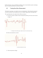
6 Implementation of a Method for Patient Data Acquisition ............................................. 45
6.1
Overview of Physiological Data ................................................................................ 45
6.2
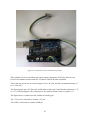
Hardware Prototype ................................................................................................... 46
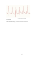
6.3
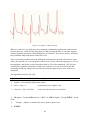
The Signal Processing Algorithm .............................................................................. 48
7 Implementation of the Client for Sending Patient Data ................................................. 52
7.1
Login to the Application ............................................................................................ 52
7.2
Collecting and Sending Data to the Server ................................................................ 53
7.3
Sending Patient Pulse Rate ........................................................................................ 54
7.4
Handling Server’s Response ...................................................................................... 55
8 Testing .................................................................................................................................. 56
8.1 Testing the Dynamic Aspect of the System ....................................................................... 56
8.2 Testing Heart Rate Measurement ...................................................................................... 61
9 Conclusion ............................................................................................................................ 63
Literature ................................................................................................................................ 65
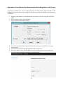
Appendix A User Manual for Measuring and Sending Data to the Server ...................... 67
Appendix B Survey................................................................................................................. 68
Appendix C Contents of the attached CD ............................................................................ 82
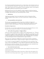
Chapter 1
Introduction
TELEMEDICINE is the use of telecommunication and information technologies to improve
patient’s clinical health status [1]. The aim is to improve a patient's health by allowing twoway interactive communication between the patient, and the physician or practitioner at the
distant site.
The term “telemedicine” was first used in the 1970s, and literally means “healing at a
distance” [2]. There is no definitive definition of telemedicine, but we can retain the one
adopted by the World Health Organization: “The delivery of health care services, where
distance is a critical factor, by all health care professionals using information and
communication technologies for the exchange of valid information for diagnosis, treatment
and prevention of disease and injuries, research and evaluation, and for the continuing
education of health care providers, all in the interests of advancing the health of individuals
and their communities” [4].
From the above definition, one can notice that emphasis is placed on the distance – meaning
that telemedicine is mainly used to eliminate distance barriers and improve access to medical
services that would often not be consistently available in distant rural communities. The given
definition also highlights that telemedicine is an open and constantly evolving science,
because it incorporates new advancements in technology and tends to respond and adapt to
the changing health needs and contexts of societies and cultures. Actually telemedicine
involves a growing variety of applications and services using two-way video, email, smart
phones, wireless tools and other forms of telecommunication technologies. These
technologies allow communication between a patient and a physician or other medical staff
with both convenience and fidelity, as well as the transmission of medical, imaging and health
information data from one site to another.
In addition to the above mentioned methods, telemedicine also uses client/server applications
to deliver advanced diagnostic methods and telemedical devices to support in-home care.
To help understand the use of telemedicine, the American Telemedicine Association has
dressed a list of examples of services provided and mechanisms used to provide those services
in telemedicine. This includes remote patient monitoring, primary care and specialist referral
services, and consumer medical health information. Telemedicine can also be used to provide
medical education. [1]
Of course these are only examples of the use of telemedicine; many other services and uses
may be involved in telemedicine. These examples, however, give us an idea of what
1
telemedicine means in practice. We can summarize the use and importance of telemedicine by
the following:
1. Its main goal is to improve patient’s clinical health status
2. It is used to overcome distance barriers by providing services at distance
and connecting patients to health staff located in different physical
locations.
3. To fulfill its goals, telemedicine uses various types of telecommunication
and information technologies.
4. Among the main benefits of telemedicine, we can mention cost efficiencies.
It has been proven that telemedicine significantly reduces the cost of
healthcare as it reduces travel times, and fewer or shorter hospital stays. It
also increases efficiency through better management of chronic diseases
[1]. Telemedicine can be beneficial to patients living in isolated
communities and remote regions, who can receive care from doctors or
specialists far away without the patient having to travel to visit them [6].
From this point of view, we can say that telemedicine can be vital and save
lives in critical care and emergency situations.
Objectives and Goals of this Thesis
The aim of this thesis is to develop a method allowing the remote patient’s data collection
using store-and-forward telemedicine paradigms in low-resource environments (lack of
diagnostic devices, limited knowledge of patients regarding telemedicine, unreliable
telecommunication, etc.).
Our motivation is to analyze the major difficulties encountered by patients in regions with
limited facilities in cardiology, e.g. developing countries and their regional health
professionals and to design a data collection system using low-cost IT solutions.
The main result is a web-based software system for patient data acquisition, storage and
retrieving for the purpose of establishing a diagnosis.
The work is broken down as follows:
First we analyze requirements from the cultural, legislative, infrastructural and IT
perspectives.
In the second chapter we mention some existing solutions and approaches used to
implement those solutions.
The following chapters describe the design of our solution, including its
implementation.
The last part of the work covers testing.
2
Chapter 2
Requirements
2.1
Business Requirements in Telemedicine
Telemedicine is a relatively young and evolving field. Building a telemedicine application
requires detailed domain analysis of users’ needs. The requirements are various and differ
from a country or a region to another. That is one of the reasons why objectives, technologies
and even philosophies of each telemedicine system will usually differ from others.
However there are of course still common requirements that every telemedicine solution
covers.
In order to have a clear understanding of specific user requirements in telemedicine in low
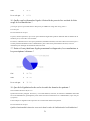
resource environments, we have made a small survey back in 2013 [35]. The aim of the
survey was to find out what are the main difficulties encountered by users while using
telemedicine.
We received 14 answers from people living in Cameroun, Congo, Czech Republic, France
and Switzerland. Unfortunately many people did not answer us, because they did not even
know what telemedicine is. But the few answers we received from different countries gave us
an idea of how some people consider telemedicine. Here is the summary:
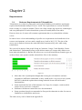
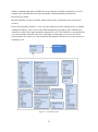
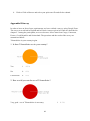
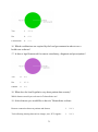
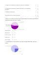
Figure 2.1
More than 18% of participants thought that existing free telemedicine software
programs are difficult to understand, so they would prefer a very easy-to-use system,
and 18.2% shared the opinion that existing solutions do not offer the needed
functionalities.
Some mentioned the lack of infrastructure. In Congo, for example, certain medical
centers do not even have a computer.
Problems with Internet connection were also mentioned.
Some questioned people recommended to first provide education in order for users to
familiarize to telemedicine and its use.
The entire survey can be found in the appendix B.
3
We had also an opportunity to discuss personally with two doctors. Both insisted on the
security of the system to protect patient’s data. According to one of them, “clear rules
regarding communication and confidentiality must be defined. Patients can be sceptic while
using such systems. They may require some proof or confirmation that the system is really
secure.”
The second doctor mentioned that a telemedicine system should allow not only patient-tophysician remote communication, but also physician-to-physician remote communication.
This can allow for example physicians in developing countries to consult their counterparts in
other countries. This can lead to better results while making diagnosis. Again confidentiality
rules must be clearly established.
In addition to this, we also made researches on the existing literature. Below are the results of
our researches regarding requirements for a telemedicine solution in low-resource
environments.
2.1.1
Requirements regarding distance barriers
As mentioned in the introduction, distance barrier is one of the basic problems faced by
people living in rural and sometimes in completely isolated regions. Indeed, rural residents
must travel longer distance than people who live in cities to get to hospitals. The challenge is
made even more complicated by the largely absent public transportation systems [7]. Because
ambulances and other emergency vehicles must travel so far, rural residents with emergencies
receive medical attention more slowly than their urban counterparts. Most of the time, people
who live in rural communities are more poor that those living in cities, so paying for the
transport to get to the hospital or to a health center may complicate life to many people. For
example a patient with chronic disease will have to spend a lot of money in order to receive
appropriate heath care.
A telemedicine system should help overcome these issues by allowing access to specialists
regardless of location. This can be done by using live video conferences or medical image or
video sharing/communication portals. A telemedicine application should allow for reliable
transmission of vital signs. This enables patient assessment by specialists in the specific
pathology and immediate reception of appropriate treatment guidelines until the patient's
arrival at hospital [8]. Allowing remote communication between patients and physicians or
nurses can not only help in solving emergency and overcome the distance barrier, but it also
helps saving money that would be spent for travelling purposes.
Many studies have been conducted to show telemedicine significantly reduces unnecessary
transport of patients or medical staff. For example, one study in Peru, in the province of Alto
Amazonas, shows an important reduction in emergency transport, which confirmed that the
system was efficient and also demonstrated that the additional costs of maintaining the system
were lower than the direct costs of the health system. [8]
4
2.1.2
Technology requirements
The success of telemedicine systems depends primarily on the various medical devices used
to collect patient information and the telecommunication infrastructure used to share data with
physicians or other medical staff.
Basically, we have the following categories [8]:
Terminal devices to capture patient biomedical signals. This includes
Electrocardiography (ECG or EKG) and sensor-based devices, such as glucose
sensors, mobility and/or position sensors for the elderly or people with reduced
mobility, temperature measurement devices etc.
Services, components and applications for healthcare management. These may be
software applications that enable service coordination (appointments, agenda setting),
patient identification, patient file management (medical records system), messaging,
data security systems, etc.
Telecommunication equipment and systems. In telemedicine, the equipment used
for both the patient and the specialist varies depending on concrete requirements.
These include telephone terminals, personal computers, PDAs, video stations,
computer peripheral equipment such as digital cameras, document scanners, high
resolution screens, etc.
Communication network. Communication network allows the transmission of
information to a referral center.
In [9] Dr. Andrew Watson recommends strong platforms for managing people, locations and
devices to address infrastructure issues. In developing countries, the choice of adequate
technologies can be very difficult. In addition to the distance barrier, patients in rural areas
must also deal with issues related to the lack of technologies. In many developing countries,
people have still to deal with issues such as lack of electricity, poor or lack of Internet
connection.
While designing a telemedicine system therefore, it is important to consider the availability of
local infrastructures and select the adequate technologies adapted to those infrastructures to fit
the local needs. A telemedicine system should propose a way to transmit data even in the
context of poor or lack of Internet connection. For this purpose, alternatives should be used,
such as mobile phones.
2.1.3
Requirements regarding Cultural Barriers
In the study Barriers to Telemedicine: Survey of Current Users in Acute Care Units,
emergency and critical care robotic telemedicine users were asked to identify the factors that
motivate and the barriers that impede the acceptance and maintenance of remote presence
telemedicine. One of the barriers revealed by the survey was the cultural barrier that occurs
because of lack of desire, or unwillingness, of some physicians to adapt clinical paradigms for
telemedicine applications [13]. As revealed by our survey mentioned above, this is most
probably due to the complexity of telemedicine applications, or to the fact that existing
5
telemedicine applications do not always fit their needs. Building a simple, easy-to-use and
flexible telemedicine application may motivate some physicians to start using it.
2.1.4
Ethic and Legal Issues
Despite of the increasing use of telemedicine, there are still a lot of discussions about the
ethical and legal issues surrounding it. Using telemedicine implies many issues of concern
regarding the legal and ethical aspects. Among them, we can mention the responsibilities and
potential liabilities of the health physicians, the obligation to maintain the confidentiality and
privacy of patient records, and the jurisdictional problems associated with cross-border
consultations.
Issues regarding privacy and confidentiality in the medical realm are not necessarily different
in telemedicine. As with conventional medicine, a telemedicine clinician has the same duty to
safeguard a patient’s medical records and keep their treatments confidential.
Transmission and storage of electronic files, images, audios, videos, etc., needs to be done
with the same caution and care as applicable to paper documents [10].
To cope with these issues, a telemedicine system must provide as much security as possible.
Users must be sure while using the system that their data are securely protected against
unauthorized users. To ensure maximum security, the system must use secure networks while
transmitting data, stored data must be encrypted, appropriate authentication and authorization
must be provided. .
2.1.5
Financial Problems
Another barrier to telemedicine is reimbursement. Medicare services lack reimbursement
terms. This is due to the fact that there are no clear standards for payment or reimbursement
for telemedicine in many countries [9].
In developing countries, there is significant limited competition for telecommunication
services, which keeps the communication cost high [32].
In addition, the equipment designed for telemedicine, including hardware and software is also
relatively expensive and therefore not accessible for many.
Due to these financial problems, the resources used by a telemedicine application must be
low-cost, meaning that the selected resources to be used must be as cheap as possible. This
includes software and hardware.
2.2
Functional and Non-functional Requirements
Based on the above analyze of business requirements, we define the following functional and
non-functional requirements for our system:
2.2.1 Functional Requirements
R1) The system must allow remote communication between patients and their health
professional, in order to eliminate distance barriers between them.
6
R2) The system should be flexible enough to allow managing different types of
objects. It should be possible to manage not only people (users), but also other objects
such as devices, documents etc.
R3) The system must allow patient to send different kinds of data.
R4) The solution should include a method for patient cardiac data acquisition
The patient will have a possibility to measure, view and send heart rate signals to his
doctor via the application.
R5) Allowed users can log in into the system and view resources they are authorized
to view. This means that the system must provide authentication and authorization.
Different access rights will be defined for different users.
R6) All patient data will be saved into a secured database.
2.2.2 Non-functional Requirements
N1) The system should allow the use of mobile phones to transmit data. This will
allow users with poor Internet connection to use the system with their mobiles
phones.
N2) The system should be easy to manipulate. As the system will be used by
people who do not necessarily have good experience in the use of IT systems, it is
required that the system will be user friendly and easy to manage.
N3) The system should be adaptable to different business cases. Each organization
has its own needs. The system should allow different organizations to adapt it to
their needs.
N4) The system must provide a high level of security. Because the system will
work with patient’s data, it must provide different security methods to protect it,
including encryption, secure transmission, authorization and authentication.
N5) The implemented solution should be low-cost. The system will primarily be
used in low-resource environments, e.g. developing countries; it should use the
cheapest possible resources. That means that technologies and resources used to
build the system must be adaptable in low-resource environments.
7
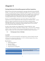
Chapter 3
Existing Solutions in Patient Management and Data Acquisition
With the advent of the Internet, many patients are eager to get information about their health
instantly. As its name says, Electronic Health Record (EHR) refers to a systematic collection
of electronic health information about an individual patient or population [15]. Sometimes the
term Electronic Medical Record (EMR) is also used to refer to EHR. In many countries, the
use of EHR is getting more and more popular. That is why many governments make
considerable efforts to improve efficiency in medical services using EHR systems.
However, even though EHR systems have proven their efficiency, many healthcare
organizations have yet to implement them. This is mainly due to financial reasons – medical
software is expensive and many care providers such as doctors, hospitals, dentists,
independent clinics and so on, have been under a lot of pressure to maintain or reduce run
costs while at the same time continuing to provide the quality patient care and customer
service expected of the medical care industry. [14]
In order to reduce the high costs of implementing IT systems in health care, many
organizations opt for the use of Open Source Software (OSS). As the open source community
continues to grow, the number of open source medical applications also grows with it. In this
chapter, we discuss some of the most used OSS in telemedicine and their characteristics.
3.1
Existing Open Source Solutions
OpenEMR
OpenEMR is one of the most popular Free and Open Source electronic health records and
medical practice management applications. It is ONC certified and supported by a strong
community of volunteers and professionals.
Key Features:
Multilanguage Support
Electronic Billing
Document management
Integrated practice management
OpenEMR
Type
Medical practice management software,
Electronic Medical Records
PHP
GNU General Public License
www.open-emr.org
Programming language
License
Website
8
Table 1: Technical overview of OpenEMR
OpenVistA
OpenVistA is a fully-integrated clinical solution with all necessary functions to run hospitals
and their clinics. It was designed to improve the care and patient safety for veterans and to be
rapidly adoptable by clinicians.
OpenVistA provides clinical, administrative, financial, and infrastructural functions. It has
been adopted for use by several other health institutions in US as well as hospitals in other
countries, e.g. Egypt, Germany, and Mexico.
However, the technology used by Vista is not based on modern computer language or
platform. [14]
Key features:
Clinical documentation
Health Information Management System (HIMS)
Patient registration
Scheduling
Notification and reminders
OpenVistA
Type
Electronic health record for all clinical field,
based on veteran’s hospital
information system
MUMPS, Delphy/Kylix
Public domain, GPL
http://www.medsphere.com/open-vista
Programming language
License
Website
Table 2: Technical overview of OpenVistA
OpenMRS
OpenMRS is a collaborative open source electronic medical record system, entirely
programmed in Java.
OpenMRS is also a community of people working to apply health information technologies to
solve problems, primarily in resource-poor environments. It has been supported by the Google
Summer of Code from 2007 [14].
Key features:
Tools for data export and reporting
Support for HIV/AIDS, Drug resistant TB, primary care and oncology
Supports open standards for medical data exchange including HL7, LOINC and IXF
Form-based tools, such as the Form Entry module and XForms module
Bidirectional synchronization with systems such as MoTeCH and TRACnet
9
OpenMRS
Infection control system for developing
countries
Java
OpenMRS Public License
http://openmrs.org/
Type
Programming language
License
Website
Table 3: Technical overview of OpenMRS
PatientOS
PatientOS has been designed from the outset to be a HER. It supports not only human
hospitals, but also veterinary care hospitals. It is a distributed web-based clinical system
written in pure Java with toolset to customize.
Key Features:
Scheduling,
Orders,
Meds,
Pharmacy,
Clinical documentation
PatientOS
Free healthcare information management
system designed for hospitals and healthcare
practitioners.
Java
GNU GPL
http://www.patientos.org/
Type
Programming language
License
Website
Table 4: Technical overview of PatientOS
GNUmed
The GNUmed project builds free, liberated open source Electronic Medical Record software
in multiple languages to assist and improve longitudinal care (specifically in ambulatory
settings, i.e. multi-professional practices and clinics).
It is made available at no charge and is capable of running on GNU/Linux, Windows and Mac
OS X. It is developed by a handful of medical doctors and programmers from all over the
world.
Key Features:
Appointment handling,
Document archive,
Medication Handling,
10
Vaccination Handling
GNUmed
Type
Programming language
License
Website
EMR, specifically in ambulatory settings
Python
GPL
http://www.gnumed.org/
Table 5: Technical overview of GNUmed
FreeMED
FreeMED is an open source electronic medical record system based on LAMP – Linux,
Apache, MySQL and PHP. The project was initiated by Jeffrey Buchbinder in the United
States in 1999. Since then, it has become an international growing up project, with thousands
of downloads and several translations.
FreeMED is currently hosted by a non-profit corporation, called FreeMED Software
Foundation. The corporation also provides commercial support for FreeMED.
FreeMED
Type
Programming language
License
Website
Electronic medical records system for
general practitioner clinics
PHP
GPL
http://freemedsoftware.org/
Table 6: Technical overview of FreeMED
SmartCare
SmartCare is an internationally distributed electronic medical records tool that was developed
by the government of Zambia in collaboration with the Centers for Disease Control and
Prevention (CDC) and many other implementing partners.
The application is currently widely used in Zambia, Ethiopia and South Africa. It was
designed in order to support clinics that need to interface internationally, but also have coexisting paper based systems. It is also built around the assumption that many of the clinics
may not have ubiquitous access to telecom systems or even reliable electrical power [16].
Key Features:
Distributed database system
Smart Card used to store health information
Touchscreen allowing the clinician to view and record patient data
SmartCare
Type
Programming language
Electronic health record system (EHR)
11
License
Website
http://smartcare.org.zm/
Table 7: Technical overview of SmartCare
CottageMed
Cottage Med is an electronic medical record software based on FileMaker. It uses templates
that interact with the FileMaker database management program.
The project was officially created in 1999 by the physician Stefan Topolski. It is one of the
first publicly distributed free EMR systems to be both open source and cross-platform for PC,
Mac & Linux in the world.
Key Features:
CottageMed became Basic accounting functions
Full and flexible access to all data fields
Powerful search functions on any and all fields
Report generation
CottageMed
Type
Programming language
License
Website
Electronic health record system (EHR)
GPL v2
www.cottagemed.org
Table 8: Technical overview of SmartCare
ClearHealth
ClearHealth is another web-based open source practice management and electronic medical
records system. Available under the GNU General Public License, it is been used by a number
of large institutions, including the Primary Care Coalition network out of Maryland, USA
[16].
ClearHealth is developed in the PHP programming language and it is able to be run on most
server configurations, in Windows, Linux or Mac OS and it uses Web Servers such as Apache
and MySQL database.
Key Features:
Scheduling
Patient registration
Electronic medical records
Electronic and paper billing
SQL reporting
Support for manipulation of with data in HL7 and Continuity of Care Record (CCR)
formats
12
ClearHealth
Practice management and electronic medical
records system
PHP
GPL
clear-health.com
Type
Programming language
License
Website
Table 9: Technical overview of ClearHealth
OpenDental
The last electronic medical records application we would like to mention is OpenDental. It
has the specification of being focused on dental care providers.
Previously known as Free Dental, OpenDental is owned and sponsored by Open Dental
Software, Inc., which is incorporated in the State of Oregon in the United States of America.
It is written in the C# programming language compatible with Microsoft .NET Framework.
Key Features:
Online patient forms
3D movable teeth
Text messaging
Mobile Web application
Kiosk
Signature pads
Multipage scanning
OpenDental
Stable release
Programming language
License
Website
C#
GPL
www.opendental.com
Table 10: Technical overview of OpenDental
3.2
Discussion about Existing Open Source Solutions
In the previous section we presented some existing Open Source solutions in telemedicine. It
is obvious, that Open Source Systems have a great potential in offering low-cost and
relatively quality electronic health records systems. This is a great alternative to proprietary
solutions for developing countries with limited financial resources.
Advantages of Open Source
Among the benefits of Open Source, we can mention the following [17]:
Open Collaboration
13
One of the most significant advantages of the use of Open Source is the fact that it involves an
open collaboration and transparency. Many people come with new ideas and share them with
others. Most of the time, they do not hesitate to criticize and improve other’s work. Instead of
being hidden, problems are exposed early, open to see and fix.
Being open, the code is free to be evaluated by a large community, which accelerates the
innovation, allows testing to be done by a broad audience. Moreover, there are no timetables
or deadlines, and release does not occur until the product is refined.
Modularity
Another great advantage of open source applications is the fact of being most of time
modular. Modularity allows software to be easily extended and to collaborate with other
systems.
Interoperability and standards
The open source programming model has being shown to facilitate development of
interoperability and standards [17]. In open source model, developers usually use existing
project as a reference and build upon it. This makes standardization quickly achieved.
Drawbacks of Open Source
From the above, we can clearly say that Open Source has many attractions. However, it also
has some barriers that must be considered. Let us mention some of them:
Lack of Non-Programmer Configurability
Open source software depends mainly on volunteers and is usually proposed ‘as is’. This may
be a problem for organizations that require EMR to be configurable to some degree [17]. This
requirement is legitimate, as clinics and hospitals or other health organizations have different
workflow and unique local environments and needs. This configuration has to be often done
by a non-technologist clinician who understands this complex workflow.
Many open source applications in EMR that are mentioned in this chapter are ultimately
configurable, but most of them are complex and require a higher level of technical expertise.
If we consider for example OpenEMR, for a non-programmer user who would like to start
using it, it may be a big challenge to even get started. The application includes many modules
that make it too complex for a beginner. Some of the modules may not be needed and it may
be very difficult to get rid of them and keep just the needed ones.
Perceived Lack of Security
As already mentioned, clinical information systems require a high level of security in order to
maintain patient privacy.
Some people are skeptical about security of open source software due to the openness of its
code [14]. Of course this perception may be wrong. Open source software can theoretically
14
be made more secure than proprietary software because it can receive input from many
developers, which allows the immediate identification of security risks.
Lack of Knowledge and Trust
Many health organizations lack knowledge about open source possibilities [17]. Some are
afraid of using an application that is free. For them “free” means without values and will
certainly not achieve their needs. They perceive in it a lack of accountability regarding
quality, security and liability.
Hospitals and providers also have to solve the question of support while opting for open
source solutions. If the system gets down, who will provide support? Complex open source
software requires qualified programmers familiar with it to provide continuous support.
Difficulty Interfacing with Proprietary Products
Another barrier to the use of open source is the difficulty to include and connect it with
proprietary resources due to the GPL license. This can occur for example with labs, eprescription networks, and decision support databases. [17]
This difficulty can be overcome if open source software uses a license that allows third parties
to keep code proprietary.
The reason why we did not choose one of them to build our system is that we did not find one
that fulfils all the requirements defined in section 2.2. According to the report mentioned in
[33], PatientOS , OpenVistA are complex and difficult to install and configure (do not meet
requirement N2). OpenEMR is not customizable and OpenMRS does not allow practitionercustomization, both do not match requirement N3. OpenDental is specific, as it focused on
dental care providers. For this reason, it does not fit N3 requirement. After personally trying
the other OSS, we can also affirm that they do not fit all our requirements, especially N3
requirement defined in the above chapter. Proprietary solutions were not considered as they
mostly do not meet the low-costs requirements.
15
Chapter 4
Solution Design
This chapter introduces the design of the solution we propose in this work.
Low-resource environments constraint for our solution requires the system to be easy to use,
flexible and configurable. Such a system will not require unnecessary resources, because
organizations will configure and adapt it to their needs, according to the available resources.
For example knowing that their Internet connection is not good, they may wish to share only
data that can be sent through the available bandwidth.
For the system to be flexible and configurable, we propose to build a generic model. The
Proposed Concept was taken from [29] and is described as follows. The idea behind the
generic model is to propose a meta model, and allow each organization that will use the
system to build its own specific model using our meta model. Meaning that, instead of hardcoding a specific concept, we let the organization define its own.
While an organization may wish to manage only patients, physicians, nurses and devices,
another one would maybe want to manage patient visits as well. Another will not have nurses
in the system at all, but only patients and physicians.
As we can see in the scenarios above, each organization has its own needs. Our ambition,
therefore, is to build a system that will be flexible enough to respond to all these needs. The
key for the success of such a system is a clever generic (or meta) data model: instead of
defining model specific classes such as Patient, Physician, Nurse, Device, etc., we simply
define a generic class called Resource Type. This meta class will then encapsulate specific
classes such as Patient or Physician. When installing the system, the organization will not
only be able to define its specific Resource Types, but also set relationships between them.
A system having such characteristics will match requirements R2, R3, N2 and N3, defined in
section 2.2.
4.1
Definitions
Resource Type
A Resource Type is a meta class used internally by the system to encapsulate specific
classes. Because the model is generic, we do not directly define specific resources like
Patient or Physician, because we do not now in advance if organizations will
incorporate them into their model or not. But we assume that organizations may wish
to have such resources and therefore we prepare a “place” for them and give them a
generic name: Resource Type. Thus, a Resource Type can be whatever: Patient,
Physician, Device, Diagnosis, Document etc.
Resource Meta Type
16
Resource Types are grouped in different categories called Resource Meta Type. For
example, Resource Types Patient, Physician and Nurse can be categorized as Human;
Hospital, Device and Room are Material; and finally Diagnosis and Medical Record
are Abstract. Human, Material and Abstract are examples of Resource Meta Types.
Resource Type Attribute
Each Resource Type has some attributes. For example if we create a Resource Type
Patient, then we can also create its attributes like Name, Age, Personal Number, and
so on. In this model, we refer to each of them as Resource Type Attribute.
Resource Type Attribute Type
Each Resource Type Attribute has some characteristics: it can be mandatory or not, it
can be binary, printable, etc. A Resource Type Attribute Type represents such
characteristics.
Resource Type Binding
Two Resource Types may have a relationship between them (i.e. a Patient can be
related to a Doctor and vice versa; a Patient might have a Diagnosis). This relationship
is called Resource Type Binding. In this relationship, one ResourceType is set as the
parent of the other.
Resource
A Resource is a specific record, or an instance of a Resource Type. If we have a
Resource of type Patient, then we refer to a given patient (i.e. Jean-Paul) as a
Resource.
Resource Attribute
A Resource Attribute is an instance of a Resource Type Attribute.
Resource Binding
A Resource Binding is a specific record of a Resource Type Binding. Assume we have
created two Resource Types Patient and Diagnosis and defined a Binding between
them. Then for a given patient (i.e. Jean-Paul), we call its diagnosis (i.e. diagnosis
number 1234) Resource Binding. In other words, the diagnosis number 1234 is a
binding of the Resource Jean-Paul (of type Patient).
Organization
An Organization is an entity, such as an institution. It can be a hospital, clinic, health
care center, etc.
In this model, it is possible to define more Organizations in the system. Organizations
are grouped in a hierarchic structure – meaning that an Organization can have one or
17
more children and one parent. One and only one Organization is set as the root. The
root Organization does not have any parent.
Resource Types are contained in different Organizations. Each Organization,
therefore, has a list of Resource Types contained within it.
User
A system User is an actor who interacts with the system. We distinguish two types of users:
o Ordinary User: a normal user with limited access to the system.
o Admin: a more privileged user, who can perform more actions than the
ordinary user (see the next part).
The admin can grant access rights to each user, allowing performing or not some specific
actions in the system.
User Group
Users are categorized into groups called User Group. Each user belongs to at least one group.
Access rights are also defined for each group.
4.2
Use Cases
This section describes the system Use Cases, i.e. the list of actions defining interactions
between an actor (user or admin) and the system.
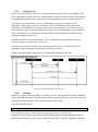
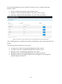
The first diagram (figure 4.1) shows all basic actions that can be performed by the system
user. An ordinary user can login into the system, view its profile, change its password and
update its personal data (if he is allowed to do so).
Figure 4.1: Use Cases – Basic actions performed by system user
18
An ordinary user can eventually view Organizations and Resource Types and possibly
manage some Resources on which he has access rights.
The admin user inherits all actions of the ordinary user, meaning that he is able to perform all
use cases an ordinary user can perform. In addition to this, admin can also manage users,
Organizations, and Resource Types.
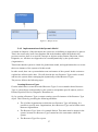
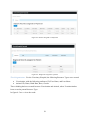
The diagram in figure 4.2 illustrates use cases for managing users. As shown in the diagram,
the admin can not only manage users (add, edit and remove), but he can also manage groups
and access rights. Thus, he can grant access rights to specific users or to a group or users.
Figure 4.2: Use Cases – Users management
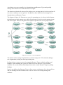
The admin can also manage Organizations, as shown in figure 4.3. This includes adding a
new Organization, editing or removing existing ones.
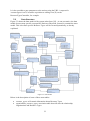
In figure 4.4 we can see use cases for managing Resource Types and their attributes and
bindings. When installing the system, the admin can create Resource Types and their
attributes. He can also define relationships between the created Resource Types by adding
bindings.
Later he can define other Resource Types, edit or remove existing ones. It is also possible to
add new bindings and new attributes and to edit or remove the existing bindings and
attributes.
19
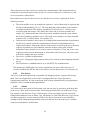
After the meta data are created (i.e. Resource Types, Resource Type Bindings), data records
can be added. Figure 4.5 shows use cases for manipulating Resources. This includes adding
new records (resources), editing and removing existing ones. It is also possible to view
Resource Bindings, add new Bindings, edit or remove the existing ones.
Figure 4.3: Use Cases – Organizations management
Figure 4.4: Use Cases – Resource Types management
20
Figure 4.5: Use Cases – Resources Management
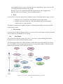
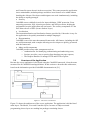
4.3
System Architecture
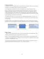
One of the main requirements of the system is to allow patients to send data to their
physicians. In order to realize this function, we use a system architecture based on REST –
Representational State Transfer. REST is a software architecture style for designing
networked applications (web services). Rather than using complex mechanisms such as
CORBA, RPC or SOAP to connect between machines, simple HTTP (Hypertext Transfer
Protocol) is used to make calls between machines [18].
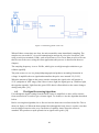
Figure 4.6: Global overview of the system
21
This architecture uses the client-server model for communication. This means that tasks or
workloads are portioned between the provider of a resource and service, called server, and
service requesters, called clients.
Rest architecture is good a choice for us, as it fits the low-resources requirement, for the
following reasons:
The client and the server are completely separated – each of them may be replaced and
developed independently [20, 21]. The only thing that connects them is the interface
existing between them. This leads to separation of concerns (SoC). Clients are not
concerned with data storage. This allows the client code to be more portable and
simpler [21]. Meaning that the client can be easily installed in patient’s post without
the need of installing a database server. The client can be simply a web form installed
in patient’s PC or mobile phone, for example. [21]
The protocol is stateless: each request is an independent transaction that is unrelated to
any previous request so that the communication consists of independent pairs of
request and response. That means that no client context is stored on the server between
requests. Operations are self-contained, and each request carries with it all the
information (state) that the server needs in order to complete it. Thus, the server is not
required to retain session information or status about each client [20]. The server code
is therefore simpler and more scalable.
The service is platform-independent.
The service is language-independent (clients can be written in other languages than the
server).
The architecture is standards-based, as we use HTTP for communication.
This architecture fulfills also our security requirement, because it allows the use of
security standards like HTTPs and it can easily be used in the presence of a firewall [18].
4.3.1
The Server
The server is the main application, responsible for managing clients’ requests and serving
them. The server application is also used for managing Resource Types, Resources,
Organizations and users. It is the central part of the system, administered by an organization
(hospital, clinic or another health organization).
4.3.2
Clients
The client side of the system will be mainly used, but not only, by patients to send their data
to the server. There may be many clients, each being specialized for a given Resource Type.
For example, if the Resource Type is Patient, then a client can simply generate a form for
filling Patient attributes such as Name, Age, ID number etc. But if the Resource Type is heart
rate data measured by a sensor and saved into a file, then a client may be specialized for
reading such file and generating attribute-value sets that will be sent to the server. Another
client can send patient’s medical data.
22
4.3.3
Description of the HTTP API
As already mentioned, both client and server use HTTP (HTTPs) for communication. Because
clients will be sending data to the server, the HTTP POST and PUT methods are used, as their
allow posting data to the server. The GET method can also be used to send data to the server,
but is less secure compared to POST because data sent is part of the URL [20]. Thus, we
choose the POST method to fit the security requirement. We use POST for inserting new data,
and PUT in case we want to update existing data. This is according the HTTP
recommendations [20].
This section describes the API or application programming interface used for the
communication between the clients and the server. Concretely, it deals with the design of the
model of resources to be shared between clients and server. This includes the identification of
the resources, the format used to represent those resources and the attribution of URL for
getting them.
Data Representation
We use the format called JSON to represent data. JSON stands for JavaScript Object Notation
and it is an open standard format that uses human-readable text to transmit data objects
consisting of attribute–value pairs. It is completely language-independent and easy for
machines to parse and generate. [19]
JSON is built on two structures:
A collection of name/value pairs
An ordered list of values
Note that this is not the internal data representation in server’s nor in client’s side. This is
used only for the communication. The server has its own data structure (described in chapter
5), which is unknown to the client. Each client may also have its own internal data
representation, and the server will not “care” of what it can be.
Making a HTTP Request
The client application addresses the server using standard HTTP request. Each request sent by
a client contains the authentication information (login and username) in the header and the
body is made of:
Resource id: id of the resource for which data are being sent. If data to be sent is for
example patient’s documents, pictures or heart rate, the resource id will be the patient
id.
Data: data to be sent to the server. The admin has to specify which users are allowed
to upload data for chosen Resource Types.
There are two kinds of data that can be sent:
o Binary data (file): this is used when data to be sent are saved in a file. It is
possible to send more files at once. Each file to be sent has the following
attributes:
23
AttributeCode: this refers to a specific Attribute of a Resource Type.
For example the Resource Type Patient may have an attribute called
Documents. So, when sending a patient’s document, the client must
specify “Documents” as the value of the attributeCode field.
Filename: the name of the file that is being sent.
Size: the size of the file.
Content: the file content. This content must be encoded into a text
using Base64 method.
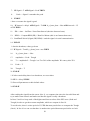
Here is an example of what it looks like:
{"files":[
{"file":[
{"attributeCode":"DOC",
"filename":"a-conrete-file-name",
"size":"file-size",
"content":"file-content-base64-encoded"}]},
{"file":[
{"attributeCode":"PICTURE",
"filename":"another-file-name",
"size":"another-file-size",
"content":"another-file-content-base64-encoded"}]}
]}
o Text data: the set of attribute–value pairs, where attributes are the Resource
Type Attributes of a given Resource Type. Example:
{"data":[
{"firstName":"John", "lastName":"Doe"},
{"firstName":"Annabel", "lastName":"Gates"},
{"firstName":"Peter", "lastName":"Steven"}
]}
It is also possible to combine both binary and text data within one request. The format is
shown in the following example:
{"data":[
{"file":[
{"attributeCode":"DOC",
"filename":"a-conrete-file-name",
"size":"file-size",
"content":"file-content-base64-encode"}]},
{"firstName":"John", "lastName":"Doe"},
{"firstName":"Annabel", "lastName":"Gates"},
24
{"firstName":"Peter", "lastName":"Steven"}
]}
As one can notice, the file field is inside the data field, and not the contrary. This must be
respected; otherwise the request will be invalid.
A complete valid request body may look like this:
{
{"resourceID":"12345"}
"data":[
{"file":[
{"attributeCode":"heartrate",
"filename":"my-heart-rate.txt",
"size":"58096",
"content":"23s84weeej4smndjd09emsjdaszzzzxxxxpoe9982njd0sdsdsdksdj8uuennenn7ee7766636636hgbnssnndddndnddgbddny09983ndjdndndndn
dnkjshdkjsdhsjkdhjkdhjksdhjksdhkjshdkjn[psdnd’]]ddddsdsdsdsdsdsd9e8snsd
jsdjsddddddddddddddddddddddddddjjnndedjdjdjdjd"}]},
{"firstName":"John", "lastName":"Doe"},
{"firstName":"Annabel", "lastName":"Gates"},
{"firstName":"Peter", "lastName":"Steven"}
]}
Making the HTTP Response
The server responds to each client request using standard HTTP response. The response
contains standard status code and possibly data required by the client.
The following table contains all status codes that can be sent by the server. Note that these are
some of the standard HTTP status codes [20].
HTTP response
Description
200 OK
Successful request.
201 Created
Request to create a new resource is successful.
204 No Content
The server fulfilled the request, but does not need to
return a response body.
25
HTTP response
Description
400 Bad Request
The request could not be processed because it contains
missing or invalid information. For example the bad
JSON format; file sent is too big.
401 Unauthorized
The credentials provided with this request are missing
or invalid.
403 Forbidden
The server recognized the given credentials, but the
user does not have proper access rights to perform this
request.
404 Not Found
URI provided in a request does not exist.
405 Method Not Allowed
The HTTP method specified in the request is not
supported for this URI.
500 Internal Server Error
The server encountered an unexpected problem which
prevented it from fulfilling the request.
501 Not Implemented
The server does not currently support the functionality
required to fulfill the request.
Table 11: status codes sent by the server
The Resource Identification
Each resource is uniquely identified by a so-called Request-URI – Uniform Resource
Identifier (URI). The URI notation is usually in the format containing a relative path, related
to some base address. The base address depends on the final placement (deployment) of the
application. It will be the (root or other specific) address of the server on which the
application will be deployed. That is why we do not consider it here.
All requests will use the following format:/service/action/resource_type/*
Service: this is the name of the service provided by server (i.e. data upload). For
illustration purposes we implemented one service called restDataTransmitter.
Action: this tells the server which action or operation to perform in order to serve the
client’s request. 3 actions (operations) are currently supported:
o add_resource: used for creating a new Resource
o add_binding: used to create a Resource Binding
o add_binary: used to send a file
If the specified Action is not supported by the server, the server returns the status code
501 in its response (Note Implemented – see table 11).
26
Resource_type: this is the name of the Resource Type related to the client’s request. It
can be patient, diagnosis, heart_rate. It must match the exact name of an existing
Resource Type on the server, otherwise, the server will return the 404 status code (Not
Found – see table 11). To determine the exact name of Resource Type, we use a
naming convention: Resource Type names used in the request are singular and
CamelCased. Examples of the correct Resource Type naming in requests are:
o Patient,
o PatientDiagnosis and
o PatientHeartRate.
The asterisk "*" means that the request may have some parameters. The parameters
are specified in the following format:
parameter1/value1/
In the case of more parameters, the format will be:
parameter1/value1/parameter2/value2/parameter3/value3
The following table gives examples of valid Request-URI:
Request-URI
/restDataTransmitter/add_binding
Description
Add a new Resource of type.
/restDataTransmitter/add_binary
/restDataTransmitter/add_resource
Used to send some binary data.
Used for example by a doctor to remotely
add a new patient to the system.
Table 12: examples of requests-URI
27
Chapter 5
Implementation of the Server
This chapter describes the implementation of the proposed solution in details, focusing on the
server side of the system. First we introduce technologies used for the implementation of the
server application, and then we describe the application structure and the data model used in
the server part of the application. Some implementation details are also discussed in this
chapter.
5.1
Used Technologies
The server application is completely programmed in the PHP script language. PHP is a
server-side scripting language primarily designed for web development (but can be used as
general-purpose programming language as well).
For the database we use the relational database management system called MySQL, which is a
popular choice of database for use in web applications.
As the HTTP Server, we use Apache, the world's most widely used web server software. This
combination of technologies (Apache, MySQL and PHP) is sometimes called LAMP or
WAMP, depending on the operating system on which there are installed. LAMP stands for
Linux Apache MySQL and PHP (Perl, Python). The “W” in WAMP means Windows. [21]
These technologies are selected to match our requirements (low-cost and low-resource). In
[20] and [30] a list of server-side programming languages is dressed. The most used ones are
PHP (82%), ASP.NET and Java. But ASP.NET is platform-dependent and requires Windows
hosting, which is most of the time more expensive then Linux hosting [30]. Furthermore,
Scripting languages like PHP could be easier to learn for beginners then Java. By choosing
PHP, we allow potential feature developers to be able to continue the development of the
system. The PHP programming language is usually used with Apache and MySQL. These two
technologies do not present any serious drawbacks for any of our requirements, mentioned in
chapter 2.
5.1.1
The Used Framework
In order to facilitate the development of the application, we use a web application framework
(WAF) called CakePHP – an open source framework written in PHP. CakePHP uses wellknown software engineering concepts and software design patterns, such as Convention over
configuration, Model-View-Controller, Active Record, Association Data Mapping, and Front
Controller. [20, 21]
Among all the features that come with CakePHP, the following are very significant: [21]:
MVC architecture
CakePHP follows the MVC (Model–view–controller) software design pattern, which
allows strict separation of the application into three main parts called Model, View
28
and Controller (more about it in the next section). This concept turns the application
into a maintainable, modular package and allows new features to be added without
breaking the old ones. Developers and designers can work simultaneously, including
the ability to rapidly prototype.
Security
CakePHP comes with built-in tools for input validation, CSRF protection, Form
tampering protection, SQL injection prevention, and XSS prevention, helping the
programmer keep the application safe and secure. The security component of Cake
also allows the use of SSL (Secure Sockets Layer).
Localization
The internationalization and localization features provided by Cake make it easy for
the application to be quickly translated in multiple languages.
Documentation
CakePHP is one of the most documented frameworks. All features, including the API
are well documented, with examples allowing new developers to quickly get started
with the framework.
Many useful components
CakePHP provides many other components such as
o Authentication: for identifying, authenticating and authorizing users,
o Session: provides a way to persist client data between page requests,
o The Request Handler: to manage HTTP and HTTPs requests.
5.2
Structure of the Application
Because the server application is developed using the CakePHP framework, it has the same
structure like all CakePHP-based applications. In this section we describe this architecture,
based on the information provided CakePHP documentation in [21].
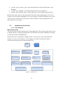
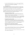
Figure 5.1: The Server Architecture
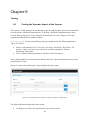
Figure 5.1 shows the architecture of the server application. The application is divided into 3
main layers: The Model, View and Controller layers. In terms of Object-oriented
programming, theses layers are nothing but packages containing classes.
29
5.2.1
The Model Layer
The Model Layer is the central component of MVC that implements the business logic and
rules of the application. It captures the behavior of the application in terms of its problem
domain, and it is independent of the user interface.
The Model directly manages data. That means that it is responsible for retrieving data and
converting it into meaningful concepts for the application. This includes processing,
validating, associating or other tasks related to handling data.
5.2.2
The View Layer
The View Layer is responsible for rendering a presentation of modeled data. It uses the
information it has available to generate an output representation to the user. The View is
completely separated from the Model Layer and it is not limited to HTML or text
representation of the data. It can be used to deliver data in different formats, such as XML,
PDF videos, music etc.
5.2.3
The Controller Layer
The aim of the Controller layer is to handle user’s requests. It collaborates with the Model
and the View layers to render a response to the client (user).
The Controller layer is nicely described in [21]: “A controller can be seen as a manager that
ensures that all resources needed for completing a task are delegated to the correct workers.
It waits for petitions from clients, checks their validity according to authentication or
authorization rules, delegates data fetching or processing to the model, selects the type of
presentational data that the clients are accepting, and finally delegates the rendering process
to the View layer.”
Controller classes contain public methods called actions.
5.2.4
Components and Helpers
As one can notice in figure 5.1, besides the 3 main layers we have just described, there are
also two sub layers that are part of the application structure: Components and Helpers.
Components
Components are packages of logic that are shared between controllers. Instead of having the
same functionality repeated in two or more controllers, we put it in special packages called
Components. Components keep controller code clean and allow the reuse of the same code
between controllers or even projects.
Helpers
Helpers are more like Components – they are used to avoid code repetition. The difference
with the Components is that Helpers are used in the View Layer (see figure 5.1). They contain
presentational logic that is shared between many views.
30
5.2.5
Request Cycle
Figure 5.1 also describes cycle of user (client) requests and the way they are handled by the
server application. In this section we explain in more details how all this works. The sequence
of communication between the 3 main layers of the application can be viewed in figure 5.2.
The request cycle starts when a user or a client requests a page or a resource in the
application. This request, just like all requests, is first of all handled by the application
Dispatcher. The Dispatcher is an object whose main functionality is to convert all requests
into controller actions. It uses the dispatched request to locate and load the correct controller.
This is actually the use of the Front Controller pattern, which provides a centralized entry
point for handling requests [20].
When the controller received the request, it may communicate with the Model Layer to
retrieve, modify or save data in case of need.
After that, the controller will proceed to delegate to the correct view object the task of
generating output resulting from the data provided by the model.
Finally, when this output is generated, it is immediately rendered to the user.
Figure 5.2: sequence diagram – request cycle
5.2.6
Routing
Routing is a feature that maps URLs to controller actions. The application routing is handled
by the CakePHP Dispatcher. The Dispatcher allows specifying the name of the controller and
the action to be performed by this controller directly in the URL.
The URL pattern format is:
http://servername.org/controller/action/param1/param2/param3
For example, the URL /resourcetypes/view maps to the view() action of the
ResourceTypesController, and /resources/add_binding maps to the add_binding() action of
the ResourcesController. If no action is specified in the URL, the index() method is assumed.
31
It is also possible to pass parameters to the actions using the URL. A request for
/resourcetypes/view/25 would be equivalent to calling view(25) on the
ResourceTypesController, for example.
5.3
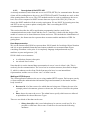
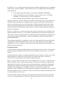
Data Structure
Figure 5.3 shows the data model of the system taken from [29]. As one can notice, the data
model does not map specific concepts like Patient or Physician. Instead, it contains the meta
model. This is because specific Resource Types will be created dynamically, as already
explained.
Figure 5.3: Data model
Below is the description of some of these meta tables:
resource_types: will contain information about Resource Types
organizations_resource_types: association table that will store the relationship
Organizations and Resource Types.
32
resource_types_resource_types: association table that will store the Resource Type
Bindings.
resource_type_attributes: will contain store Resource Type Attributes.
resource_type_attribute_types: will store Resource Type Attributes characteristics.
Besides these tables, there are also other tables that will contain Organizations, Users, User
Groups, and Access Roles and Rights. User access rights are defined in different levels: users
can have access on Resource Types and/or on their Attributes, and on Organizations. The
same applies for user groups.
5.4
Implementation Details
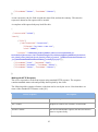
5.4.1 Class Diagram
Model Classes [29]
The model classes form the business layer in the application. They represent data and are used
to manage almost everything regarding data. This includes processing, validating, associating
or other tasks related to handling data.
Each model class corresponds to a database table. A model can be associated with other
models, as we can see it in figure 5.4. For example, the model class ResourceType is
associated with the model class ResourceMetaType.
Figure 5.4: Model classes
33
From figure 5.4 we can notice that all model classes extend the application model, AppModel,
which in turn extends CakePHP’ s internal model class. The CakePHP internal model comes
with methods for
retrieving data from the database, such as find(), findById(), findAllBy();
saving or updating data into the database, such as create(), save(), saveField(),
saveMany(), saveAssociated(), saveAll(), updateAll();
and for deleting data from database, such as delete() and deleteAll().
Thanks to inheritance, all these methods are available for all model classes. By extending the
CakePHP model class therefore, each model class is endowed with all the functionality it
needs to create queries and to save and delete data. This helps keep the model classes clean
and avoids writing multiple queries to communicate with the database. That is the reasons
why the majority of the application model classes are empty (contain simply the declaration,
but have no methods).
However, in some cases, a model class may need specific queries that are not available in the
inherited methods. In this case, we can define a method that will perform the needed queries.
This is the case for the model class Resource. Besides the inherited methods, it implements its
own methods: getResourceBindings(), saveResourceBinding(), getResourceBinaryData(),
getBinaryDataByID().
The application model class, AppModel, is used as the intermediate class between all model
classes and the CakePHP internal model. For now it is empty. But the idea of having the
AppModel is to have a possibility to define functionality that should be made available to all
models within the application.
Controller Classes
Controller classes are kind of middle man between the Model and View layers. After routing
has been applied, the Dispatcher chooses the correct controller to process user’s or client’s
request.
Controllers provide a number of methods that handle requests. These are called actions. Each
public method in a controller is an action, and is accessible from a URL. An action is
responsible for interpreting the request and creating the response.
Figure 5.5 shows all the controllers of the server application. As we can see, controllers don’t
talk to each other. They even ignore the existence of each other. This does not apply for the
AppController: this class is the parent class to all the application’s controllers, meaning that
all application controllers extend the AppController class. AppController itself extends the
controller class included in the CakePHP core library. As in the case of models, the
inheritance of the CakePHP core controller allows the application controllers to use CakePHP
functions available in the core controller. This prevents us from writing some boilerplate code
we would otherwise need to write.
As already stated, controller classes do not communicate between them, but each controller
can use its corresponding model. When the model name matches that of the controller, this
34
model is automatically made available for access and the controller can directly use it. For
example, the controller ResourceTypesController will automatically initialize the
ResourceType model.
But the controller can also load other models and use any component class (see the next
section).
In the class diagram of figure 5.5, one can notice that most of the controllers have a method
called beforeFilter(). This is one of the callback functions provided by the CakePHP core
controller, used to insert logic around the request life-cycle. This function is executed before
every action in the controller. We use it especially to control the user access. So, before
processing the user request, we first control in this method if he has access to the resource is
requiring or not.
Figure 5.5: Controller classes
35
Component Classes
Component classes are functions that are shared between controllers. They are best used for
code that is used in many (but not necessarily all) controllers.
In the application we implement for now two components, as show in figure 5.6: the
ResourceNameSolverComponent and the AuthorizedComponent. The first one is used to
manage the naming convention. Given a Resource Type name, this component is able to
render the exact name of the database table of this Resource Type and also the model class
representing this Resource Type. It does so by applying the naming convention rules (see the
section Naming Conventions for more details).
The AuthorizedComponent is used to ensure the application authorization. Concretely, it is
used to determine if the identified/authenticated user is allowed to access the resources they
are requesting.
In addition to these two components, the application also uses the components provided by
the framework, such as Pagination, Sessions, Authentication, Security and Request Handling.
Figure 5.6: Component classes
Helper Classes
Helpers are the component-like classes for the presentation layer of the application. They
contain presentational logic that is shared between many views.
Figure 5.7 shows the application Helper sub layer. Just like models extend AppModel and
controllers extend AppController, all helpers extend a special class, AppHelper, which in turn
extends the CakePHP Helper class.
The application implements just one helper class called TreeHelper. This helper is used to
display Organizations in hierarchic order, i.e. in a tree-like structure.
36
Figure 5.7: Helper classes
5.4.2 Implementation of the Dynamic Model
As stated in chapter 4 of this document, the system we are building is supposed to be generic.
That is the reason why in all class diagrams and in the database model described in the
previous sections, there is no specific concepts or objects such as Patient, Physician, Nurse,
Diagnosis, etc. All these are supposed to be created dynamically by the system owner
(Organization).
That means that the system is a kind of a global meta model, and organizations have to create
their own instance of the system to fit their needs.
In other words, how can a system admin create an instance of the system? In this section we
explain how all this can be done. We will describe the way Resource Types can be created
and how the system allows managing the dynamically created Resource Types.
The process follows the following steps:
Creating Resource Types
First the admin has to create the needed Resource Types. Let us remember that a Resource
Type is a meta object used internally by the system to encapsulate specific objects, such as
Patient, Physician, Device, Diagnosis, Document etc.
So, by creating a Resource Type we mean creating a specific instance of the Resource Type
object. This is done by providing the following attributes:
The id of the Organization to which the new Resource Type will belong. It is
possible to specify more Organizations, has a Resource Type can be bind to more
than one Organization.
The Resource Type Name: for example Patient. This name must be unique in the
system, because two Resource Types cannot have the same name within the
system.
The Resource Type Description.
37
The Resource Type Attributes and their characteristics: such as Name, Age, etc.
When all the needed information is specified, the request for creating the new Resource Type
is sent to the ResourceTypesController who is responsible for creating Resource Types. The
following actions are then performed by the ResourceTypesController:
Some checks are performed to make sure that the specified data are valid.
A new database table is created. The name of the table matches the one of the
Resource Type and the table columns correspond to the given Resource Type
Attributes.
A new record (new row) is inserted into the database table resource_types. The record
contains the Resource Type name and description. This table keeps track of all
Resource Types.
New records are inserted into the database table organizations_resource_types, to
specify to which Organizations the new Resource Type belongs.
New rows are inserted into database table resource_type_attribute_types, to record the
new Resource Type Attributes and their characteristics.
A new model class is generated in the Model layer (defined in a new generated file).
The name of this class corresponds to the name of the Resource Type. The created
model class is empty, meaning that it contains no logic, but just the class definition,
which looks like:
<?php
/*
This file was generated automatically
*/
/**
* This class represents the Resource of Type: $RESOURCE_TYPE_NAME
*
* @author System
*/
class $RESOURCE_TYPE_NAME extends AppModel {
//no code is needed here
}
The new created class does not need to implement any logic, because it extends the
AppModel, which in turns extends the CakePHP core Model. As already explained,
this inheritance allows new created model class to be endowed with all the
functionality it needs to manage data in the database, that means create, save and
delete data etc.
38
That is all! The new Resource Type is created and ready to be used. No controller
class is needed, because there is one controller that helps manage all the dynamically
created Resource Types – the ResourcesController (see the third step).
Figure 5.8 shows the sequence of communication between different objects to create a
new Resource Type. The ResourceTypesController communicates with the
ResourceType and OrganizationResourceType models to create and save Resource
Types.
Figure 5.8: Adding a new Resource Type
Adding Bindings
After Resource Types are created, the admin may wish to define a relationship between two
Resource Types. This relationship is what we call Resource Type Binding. The creation of
Resource Type Bindings is also handled by the ResourceTypesController.
In order to define a Resource Type Binding, the following must be specified:
The names of the two Resource Types between which the Binding has to be created.
One of the two Resource Types has to be set has the parent of the other.
To create the Binding then, the ResourceTypesController performs the following:
Make sure that this Binding does not exist in the system already.
Create a new database table for this Binding. The name of the new table matches the
name of the two Resource Types. To generate the right table name respecting the
naming convention, the ResourceTypesController calls the
ResourceNameSolverComponent, which applies the naming convention.
39
A new row is inserted into the table resource_types_resource_types. The record
contains the id of the parent Resource Type and the id of the child Resource Type.
This helps keep track of the Resource Type Bindings.
Managing Resources
Resource Type objects are not directly known by the system (they are not part of classes
modeled in the system), because they are created dynamically. Here we explain how the
system manages them. This includes creating new instances of these dynamically created
Resource Types (which means adding new records in the new generated tables).
This is possible thanks to the meta tables. They store information about the dynamically
created tables. That is why before (or after) creating a new Resource Type, we store
information about it into the meta table resource_types. In the same way we also save
Resource Type Attributes, Resource Type Bindings into meta tables.
Viewing the created Resource Types
All dynamically created Resource Types are immediately visible via the view ()
method of the ResourceTypesController controller class. This method accepts one
parameter – the id of the Organization. So, by typing
resourcetypes/view/some_existing_organization_id, the user can view the list of all
created Resource Types of the given Organization (if he has access rights). What this
method does is simply query on the table resource_types, where all Resource Types
are stored (using of course an appropriate model to talk to the database).
Viewing Records of a Resource Type
Viewing records from the dynamically created table is ensured by the controller
ResourcesController, via its method viewAll(). The viewAll() method accepts the
Resource Type ID as parameter. First it gets the Resource Type Name, then it tries to
load the corresponding model of this Resource Type, which is then used to query on
the table corresponding to the Resource Type (i.e. on the generated table).
Adding a Record into a Dynamically Created Table
Adding records (or Resources) into a generated table is also done using the
ResourcesController and follows the same logic. The edit also follows the same
strategy.
To add a record, the method add() of the ResourcesController is called. This method
also accepts the Resource Type ID as parameter in order to be able to determine the
right Resource Type table into which the new record has to be inserted.
Figure 5.9 shows the message sequence chart between different objects while adding a
new or editing an existing Resource.
40
Figure 5.9: Adding a Resource
View Resource Bindings
The ResourcesController allows also viewing Resource Bindings. This is done in its
method viewBinding(), which accepts 3 parameters: the id of the parent Resource
Type, the id of the Resource and the id of the child Resource Type.
If for example we have created Resource Types Patient and Diagnosis and defined a
Binding between them, then to view a given patient’s diagnosis, the following
arguments must be provided
o The id of the Resource Type (here the Resource Type is Patient).
o The id of the patient whose diagnosis has to be displayed.
o The id of the child Resource Type (here Diagnosis).
Adding a Binding Record
To add a Resource Binding (for example to add patient’s diagnosis), we use the
method addBinding() of the ResourcesController(). Just like the viewBinding()
method, the addBinding() also accepts 3 parameters: the id of the parent Resource
Type, the id of the Resource and the id of the child Resource Type.
In figure 5.10, we can see the sequence of interactions between ResourcesController
and other objects when adding a new Resource Binding.
41
Figure 5.10: Adding a Resource Binding
Naming Conventions
From the above section, we have learned that to be able to retrieve data in the dynamically
created tables, the application used the information stored in the meta tables. That means that
the application first gets the Resource Name from a meta table, which allows it then to query
on the dynamically created table using that name.
For all this to work properly, it is necessary to respect certain conventions when it comes to
naming such tables. This is very crucial, as the application relies on the correct table names, to
be able to work with it.
To achieve this, a couple of rules are necessary. In this section we define those rules and
explain how they are implemented.
Model Naming
As already stated, model class names are singular and CamelCased. The model name
is important, as it corresponds to a database table. This “correspondence” is made
possible by using the model class name.
Resource Type Table Naming
Table names corresponding to models are plural and underscored.
Examples of conventional model and corresponding table names are shown in the
following table:
Model Name
Patient
MedicalProblem
HeartRate
Table Name
patients
medical_problems
heart_rates
Table 13: example conventional model and table names
42
Table field names are also singular. The table fields with two or more words are
underscored. For example: First Name => first_name; ID Number => id_number.
Resource Type Binding Table Naming
Resource Type Binding tables are used to map relationships between Resource Types.
They must be named after the model tables they will join, arranged in alphabetical
order (medical_problems_patients rather than patients_medical_problems).
Here are some examples:
Table Name 1
patients
patients
organizations
Table Name 2
medical_problems
heart_rates
resource_types
Binding Table Name
medical_problems_patients
heart_rates_patients
organizations_resource_types
Table 14: example conventional binding table names
These convention rules must be respected when creating a Resource Type and when trying to
retrieve information stored in the dynamically created model. All this is solved by the
component ResourceNameSolverComponent, which implements algorithms allowing
determining the right model and table names according to the above defined rules.
This component implements a couple of methods, among which we can mention:
getResourceTableName(): accepting a Resource Type name as parameter, this
method returns the corresponding table name. For example, if the argument is Patient,
the method will output patients. The output will be the same if the given Resource
Type name is patient, patients or Patients. The input Medial Record will have as
output medical_records.
getResourceModelName(): this method also accepts a Resource Type Name as
parameter an returns the corresponding model name. For the input Medical Record (or
medical record), the method will produce MedicalRecord.
getResourceBindingTableName(): This method accepts two parameters – the parent
Resource Type name and the child Resource Type name, and returns the
corresponding binding table for the two Resource Types.
Note: these conventions assume that used names would be in English.
5.5
Security
The server ensures data security in different levels:
Authentication
Each user interacting with the system (remotely via a client or not) must login by providing
valid password and login. The user password is encrypted bcrypt, a key derivation function
that a salt per user to protect against rainbow table attacks.
Authorization
43
The authorization can be specified for each Resource Type and also for each attribute of a
Resource Type. For each Resource Type/Resource Type Attribute, the following access rights
can be defined:
View: defines access for viewing a Resource Type/Resource Type Attribute
Insert: access for adding new records
Update: access for updating
Delete: access for deleting
Encrypt: access for encrypting
Import: access for uploading data
Export: access for exporting data
This offers security and respects at the same time our requirement N3 defined in chapter 2,
about flexibility. Indeed, instead of deciding who has access to what, the system organizations
define their own access roles, according to their needs.
Secure data transport
When communicating with the clients, the server used HTTPS protocol, which uses SSL to
encrypt data.
Data are encrypted
All patients’ data are encrypted and saved into database. Saving data into database allow
effective access control on them.
44
Chapter 6
Implementation of a Method for Patient Data Acquisition
In this chapter, we discuss the implementation of a low-cost method for patient physiological
data acquisition. Our focus is to provide patients with a system allowing them to measure
their heart rate and to be able to send it to their help professionals.
We start the description of the implementation by first providing an overview of physiological
signals and different methods used to measure heart rate.
6.1
Overview of Physiological Data
Human body is constantly communicating information about a person’s health state. This
information is defined by variety of physiological parameters, such as heart rate, blood
pressure, oxygen saturation levels, blood glucose, nerve conduction, brain activity and so
forth. [23, 24]
Many instruments have been developed to capture those physiological parameters, such as
sensors placed on the body or implanted. These measurements provide useful information
upon which clinicians can make decisions.
However, not all physiological parameters are informative and can be used to evaluate
patient’s health state. Moreover, the measurement of some of them may require special
conditions and expensive medical equipment and materials. [23]
It has been suggested that assessing the cardiovascular and respiratory systems by measuring
heart rate, respiration rate, temperature, and blood pressure provide significant insight in
patient health state [23].
The so-called vital signs are useful in detecting or monitoring medical problems. Let us see in
more detail the methods used for measuring human heart rate.
Heart Rate Monitoring Methods
To monitor heart rate, two primary technologies are available to device manufacturers: ECG
(Electrocardiography) and PPG (Photoplethysmography).
ECG or Electrocardiography is a representation of the electrical activity of the heart over a
period of time using electrodes placed on a patient's body. Just like other muscles, cardiac
muscle contracts in response to electrical depolarization of the muscle cells. The sum of this
electrical activity, when amplified and recorded, is what we call ECG. [25]
PPG or Photoplethysmography is a light-based technology to sense the rate of blood flow as
controlled by the heart’s pumping action. The technology consists of a light source and a
detector, with red and light-emitting diodes (LEDs) commonly used as the light source.
45
The PPG sensor monitors changes in the light intensity via reflection from or transmission
through the tissue. The changes in light intensity are associated with small variations in blood
perfusion of the tissue and provide information on the cardiovascular system, in particular, the
pulse rate. [25]
A photoplethysmographic waveform is made of two components, as shown in figure 6.1: the
Direct Current (DC) component corresponding to the detected transmitted or reflected optical
signal from tissue and venous blood, and the Alternating Current (AC) component that shows
the changes in blood volume that occurs between the systolic and diastolic phases of the
cardiac cycle. [27]
Figure 6.1: Variation in light attenuation by tissue (taken from [27])
6.2
Hardware Prototype
In order to monitor patient’s heart rate, we use the PPG (Photoplethysmography) method,
instead of ECG, because it is cheaper and simpler than ECG [26].
As figure 6.2 shows, the hardware prototype we propose will allow a patient to measure its
heart rate using the Pulse Sensor which is connected to the Arduino board, connected itself to
the computer via USB- AB connector. The following components are used:
A pulse sensor called Pulse Sensor Amped.
Arduino Duemilanove board with the microcontroller ATmega328.
And a USB A-B cable for serial communication.
46
Figure 6.2: Components used for the hardware prototype
This solution is low-cost and does not require many components. The Pulse Sensor costs
$24.99, the Arduino board around $21.16 and the USB A-B cable around $4
The board can operate on an external supply of 6 to 20 volts, but the recommended range is 7
to 12 volts [34].
The Pulse Sensor has a 24” flat color coded ribbon cable with 3 male header connectors (+3V
to +5V, GND and Signal). The connection to the Arduino board is done as (figure 6.3):
The Signal wire is connected to the Arduino A0 analog pin
The +5V wire is connected to Arduino +5V pin
The GND is connected to Arduino GND pin
47
Figure 6.3: Measuring patient’s heart rate
When all these connections are done, the microcontroller starts immediately sampling. The
samples are sent to the PC via serial communication and can be viewed or saved into a file
using a serial port terminal (COM), such as RealTerm or Tera Term. Data saved in a file can
then be sent to the server using the client application (this process is described in the next
chapter).
The sampling frequency is set to 500 Hz, which gives us a high enough resolution to get
reliable signal28].
The pulse sensor we use is a photoplethysmograph and produces an analog fluctuation in
voltage. It amplifies the raw signal and normalizes the pulse wave around V/2 (512V).
When the amount of light on the sensor remains constant, the signal value will remain at
512V (midpoint of ADC range). But if there is more light, the signal goes up. With less light,
the opposite appends. Light from the green LED, that is reflected back to the sensor changes
during each pulse. [28]
6.3
The Signal Processing Algorithm
Even though the signal coming from the Pulse Sensor is amplified, we have still to clean it
from external noise in order to get a cleaner signal. To do that, we use the algorithm described
below.
Before viewing this algorithm, let us first see how the heart rate waveform looks like. This is
shown in figure 6.4. When the heart pumps blood through the body, there is a pulse wave that
travels along all arteries to the very extremities of capillary tissue where the sensor is
attached. This produces a rapid upward rise in signal value (peak). [28]
48
Figure 6.4: Example of a PPG waveform
What we want to do is to find successive moments of instantaneous heart beat and measure
the time between, called the Inter Beat Interval (IBI). Having the IBI, we can then compute
another important parameter called BPM (beats per minutes). This can be done by following
the predictable shape and pattern of the PPG wave.
There exists many methods allowing finding the instantaneous moment of heart beat. Some
choose the upward rise event (the peak); others say it is better when the signal gets to 25% of
the amplitude, and finally certain researchers think is 50% of the amplitude. [28] We have
tried all these methods, and found out that better results were in our case observed while
measuring the IBI by timing between moments when the signal crosses 50% of the wave
amplitude.
The algorithm looks like this [28]:
Algorithm 1: Process the Heart Rate Analog Signal
1:
Signal ← Read Analog Signal from Sensor
2:
time ← time + 2
// time between two signals: 2 ms
3:
interval ← time - lastTime;
// time since the last beat to avoid noise
4: IF Signal < Trough AND interval > (IBI/5)*3) AND if Signal < Trough THEN // avoid
noise
5:
6:
Trough ← Signal // remember the lowest point in pulse wave
END IF
49
7:
IF Signal > T AND Signal > Peak THEN
8:
Peak ← Signal // remember the peak
9:
END IF
// here we assume the signal is good
10: IF interval > delay1 AND Signal > T AND Is_a_heart_beat = false AND interval > 3/5
of IBI THEN
11:
IBI ← time – lastTime // Inter-Beat Interval (the time between beats)
12:
BPM ← ComputeBPM (IBI) // Beat Per Minute (this is our famous heart rate)
13: SendDataToSerial (Signal, IBI, BPM) // send the signal via serial communication
14: END IF
// after the heartbeat, values go down
15: IF Signal < T and Is_a_heart_beat = true THEN
16:
Is_a_heart_beat ← false
17:
amplitude ← Peak - Trough
18:
T ← amplitude/2 + Trough // set T at 50% of the amplitude. We can try also 25%
19:
Peak ← T
20:
Trough ← T
21: END IF
// if after certain delay there is no heartbeat, we reset values
22: IF N > delay2 THEN
23: Reset all parameters to their default values
24: END IF
After reading the signal from the sensor (line 1), we compute time since the last valid beat and
try to make some controls and make sure that the signal is really a heartbeat.
In lines 5 and 8 we keep track of the highest and lowest values of the PPG wave (Peak and
Trough) in order to get the accurate amplitude, which we compute in line 18.
To avoid noise, there is a time period of 3/5 IBI that must pass before we compute the Trough
(line 4). In line 10 we can see that there is another time period that must pass before we look
50
for a valid heartbeat, in order to avoid high frequency. This time period can be for example
250 milliseconds (which is equivalent to a maximum of 240 BPM).
After that delay, if the Is_a_heart_beat Boolean parameter was set to false, then we know that
we have a heartbeat. We can then compute the BPM and send the signal via the serial port.
Note that the function implementing this algorithm must be called every 2 milliseconds (as
described in the previous section).
The BPM is derived every beat from an average of the previous 10 IBI times. We compute it
by using the following algorithm.
Algorithm 2: ComputeBPM (IBI)
1:
Is_a_heart_beat ← true
2: lastTime ← time
3: total ← 0
4: N ← 10
5: FOR all i = 0 : N -2 DO
6:
rate[i] ← rate[i+1]
7:
total ← total + rate[i]
8:
END FOR
9: rate[N - 1] ← IBI
10: total = total + rate[N - 1]
11: total /= N
// add the latest IBI to total
// average the last 10 IBI values
12: BPM ← 60000/total
13: RETURN BPM
These algorithms are directly implemented on the microcontroller using Arduino development
environment (IDE). This IDE is free and easy to use. The next chapter describes how to send
the measured data (but not only) to the server.
51
Chapter 7
Implementation of the Client for Sending Patient Data
Because the server is using a standard protocol HTTP (HTTPs) and JSON format for the
communication with client applications, the client can be whatever that supports this protocol
and format. It can be a Web, Desktop, or Mobile application; it can be implemented using
PHP, Java, etc.; it can run on Windows, UNIX, or other Operating Systems. Also, because the
server is programmed to support dynamic creation of resources, there may be many clients,
each being specialized in sending specific resources to the server using the communication
protocol described in chapter 4.
All this means that the server is ready to communicate with different clients, and this is what
we wanted: develop a central component (server) and allow different types of clients to
communicate with it. What this means for organizations that will use the system is that they
have the possibility to develop different clients according to their needs to share data with the
server. The proposed architecture allows client application to be divers and simple. Any
application supporting HTTP control can communicate with the server by using the IP defined
in chapter 4. It can be for example a simple web form installed in patient’s PC or mobile
phone, or another telemedicine application such as OpenEMR
That said, in this work we implement a PHP web-based client to allow users to send binary
data to the server. The objective of this client is double: test the server functionalities to make
sure it does well its work, and serve as a prototype that will help in the implementation of
other clients.
The client is also implemented using the CakePHP framework. The principles of the
implementation are therefore the same as in the case of sever (see chapter 5). That is why we
will not repeat these implementation details here. Instead, we will focus on how the client
works, and how users can collect and send their data to the server.
The client is simple and does not have any data structure. It does not communicate to any
database. It implements the following functionalities: allowing users to log in, collecting user
data using a web form, sending data to the server, handling server’s response. This chapter
describes all these functionalities in detail.
7.1
Login to the Application
To be able to send data to the server, the user must be authenticated. Before the client
application shows the form for the user to input its data, it first tells the user to login.
However, it does not authenticate the user but let the server do the authentication. This is
because the client does not have any database to compare user credentials. Hence, when the
user log in, the client application simply remembers (saves into Session) the user’s password
and login and will use them later when contacting the server to send data for state-less
communication.
52
7.2
Collecting and Sending Data to the Server
As already mentioned, this client is designed to send binary data (files) to the server. To do
so, the client proposes a form to load the file to be sent to the server. When sending data, the
following must be provided by the user via the form:
The name of the Resource Type (i.e. Patient, Diagnosis). This must match the
name of an existing Resource Type in server’s side.
The Resource ID. In case of Resource Type Patient, for example, this will be the
patient’s id.
The Resource Type Attribute name. This also must match the name of an existing
Resource Type Attribute name in server.
Load the file containing data to be sent.
All this depends on Resource Types that have been created in server. If for example the server
has a Resource of type Patient with attributes Document, HeartRate, and Picture and all have
a characteristic of been binary, the user can send patient’s document, heart rate or picture. The
parameters will be in this case:
Resource Type name: Patient.
Resource Type id: 12344.
Resource Type Attribute name: Document or HeartRate or Picture.
Once data are specified, the client proceeds by preparing the request to be sent to the server.
The request will have the format described in chapter 4, and will look like:
{"data":[
{"resourceType":"Patient"},
{"resourceID":"12344"},
{"file":[
{"attributeCode":"Picture",
"filename":"picture1.txt",
"type":"text",
"size":"58096",
"content":"23s84weeej4smndjd09emsjdaszzzzxxxxpoe9982njd0sdsdsdksdj8uuennenn7ee7766636636hgbnssnndddndnddgbddny09983ndjdndndndn
dnkjshdkjsdhsjkdhjkdhjksdhjksdhkjshdkjn[psdnd’]]ddddsdsdsdsdsdsd9e8snsd
jsdjsddddddddddddddddddddddddddjjnndedjdjdjdjd"}]}
]}
Concretely, the client will extract information concerning the file (name, type and size),
transform the file content into a text using 64base transformation, and finally encode all this
into JSON format. That will form the body of the request.
53
In the header, the client must also specify the user credentials (login and password) for the
authentication. That is all, data can be now sent to the server. The next step is to handle
server’s response.
7.3
Sending Patient Pulse Rate
The process for sending patient’s heart rate is exactly the same as described in the previous
section. The appendix A contains a User Manual describing how to measure pulse rate and
save the measured samples into a file. Because patient’s heart rate data is saved into a file,
sending it to the server is the same as sending any other file to the server.
After sending pulse rate data to the server, it is expected that the server will print it as a chart
for a physician or a clinician to view it and evaluate the patient’s health state. Below is the
description of this process.
Viewing Patient’s Pulse Rate
Each Resource Type Attribute defined in server has a sub-attribute or characteristic called
is_chart, whose value can be either 0 (false – default value) or 1 (true). When its value is set
to 1, the server will automatically provide a button “View Chart” to print it as a graph. This is
ensured by the server’s Controller ResourcesController, in the method viewBinary. This
method expects data containing in file to be in array, with the following format:
[series1, series2, series3, …]
And each data series is consist of values of x axis and y axis.
[x, y]
Put it all together, data will be in the following format:
[ [x1, y1], [x2, y2], [x3, y3], [x4, y4] ]
But sometimes the value of y is known or is constant and there is no need to specify it. In this
case, the following format is also acceptable:
[ x1, x2, x2, x3, x4, x4]
When there are too many samples (i.e. more then 500), data will be automatically divided into
smaller arrays and will be displayed progressively. The user can update a chart periodically
to get a real-time effect by using a timer to insert the new data in the plot and redraw it. Time
between updates is specified in milliseconds.
Heart rate samples measured by the Pulse Sensor as described in previous chapter are saved in
a file in the above format, i.e.: [ [x1, sample], [x2, sample], [x3, sample], [x4, y4 sample],
where sample is either the Inter-Beats Intervals (IBI) or Beats Per Minutes (BPM) and x
timestamp.
54
7.4
Handling Server’s Response
After sending data to the server, the client expects the server to send some feedback. The
server’s response in this case contains essentially a status code, such as described in table 11.
One of the client’s tasks is to receive and interpret the server status code. The following rules
apply when it comes to interpreting status codes:
If the code is in the range of 200-299, this means that everything is OK (especially
when the status code value is 200). The client then lets the user know by printing a
OK message:
OK! Data successfully sent.
If the code is in the range of 400-499, there is an error in client’s side (forbidden,
user not authenticated, not allowed, bad request, etc.). The client prints an error
message: Oops! The server could not process your request. It seems like there is
something in your request that the server does not like. Here is what he said: bad
request.
When the code is between 500 and 599, this means that an error occurred in server’s
side. In this case, the client also prints an error message:
Oops! It seems like the server encountered a serious problem while processing your
request. Please, try it again later
55
Chapter 8
Testing
8.1
Testing the Dynamic Aspect of the System
The objective of this testing is to test that the system is really dynamic and can be customized
to fit the needs of different Organizations. To do that 3 different Organizations have been
created: Bilongo Hospital, Central Hospital Yaoundé and Veterinary Hospital. For each
Organization data has been added as follow:
First Organization: for the testing Bilongo Hospital Organization, the following Resource
Types are created:
Patient, with attributes: ID, First Name, Last Name, Birth Date, Birth Place, ID
Number, Address, Gender, Age and Grade, and binary attributes: Pictures,
Documents, Heart Rate.
Visits, with the following attributes: ID, Date, Time, Description
Then a binding has been created between Patient and Visit, where Patient has been set as the
parent Resource Type.
Figure 8.1 shows the two Resource Types displayed by the system.
Figure 8.1: Testing Resource Types for “Bilongo Hospital” Organization.
The following functionalities have been tested:
Creating new records: new patients and visits where created.
56
Viewing records: the created patients/visits could be viewed
Editing a record: created patients/visits were edited.
Removing: some created patients/visits were removed.
Bindings: visits were assigned to patients.
All tested system functions worked as expected. The following figures show the
screenshots realized while testing.
Figure 8.2: Created patients in “Bilongo Hospital” testing Organization.
Figure 8.3: Adding a visit for a given patient.
Second Organization
57
For the first Organization (Central Hospital Yaoundé) we have created the following
Resource Types:
Patient, with the same attributes described previously.
Diagnosis, with the following attributes: ID, Name, Code, and Type.
Physicians, with the following attributes: ID, First Name, Last Name.
Figure 8.3: Resource Types created for the “Central Hospital Yaoundé” Organization.
Then a binding has been created between Patient and Diagnosis, and between Physician and
Patient.
The following functionalities have been tested:
Creating new records: new patients and physicians where created.
Viewing records: the created patients/physicians could be viewed
Editing a record: created patients/physicians were edited.
Removing: some created patients/physicians were removed from the.
Bindings: patients were assigned to physicians, and diagnoses were assigned to
patients, (figures 8.4 and 8.5).
58
Figure 8.4: Patients assigned to a Physician
Figure 8.4: Diagnoses assigned to a patient
Third Organization: For the Veterinary Hospital, the following Resource Types were created:
Veterinarian, with the following attributes: ID, First Name, and Last Name.
Animal: ID, Name, Birth Date, Race, Gender.
Then a binding has been created between Veterinarian and Animal, where Veterinarian has
been set as the parent Resource Type.
In figure 8.5 we ca view the result.
59
Figure 8.5: Testing Resource Types for the “Veterinary Hospital” Organization
The following functionalities have been tested:
Creating new records: new animal patients and veterinarians where created.
Viewing records: the created animal patient/veterinarians could be viewed
Editing a record: created animal patients/veterinarians were edited.
Removing: some created animal patients / veterinarians were removed from the.
Bindings: animal patients were assigned to veterinarian (figure 8.6).
Figure 8.6: Resources of type Animal assigned to a Veterinary
Results: Three different business cases were created, with different needs. The first case can
be adapted to a physician or doctor who would like to manage its patients and their visits. The
second case can be used by a clinic for example, having more physicians, patients, with
patients having their diagnoses saved in the system. Finally the last case illustrates that the
system can be used also as a Veterinary center.
60
Different Resource Types with different attributes where created, and the system was manage
them. All tested functionalities worked successfully.
8.2
Testing Heart Rate Measurement
The hardware prototype was tested by four users independently. Each of them has measured
its heart rate and sent it successfully to the server using the implemented client application.
The experiments have been made in three different scenarios:
1) We tried to measure with the sensor not attached in the body at all: the result is shown
in figure 8.7
8.7 Example of measured signal, when the sensor is not attached on body
2) The sensor attached on ear lobe
8.8 Sensor attached on ear lobe
3) The sensor placed on finger
61
8.9 Sensor placed on finger
Conclusion:
When attached on finger, the sensor measured real hear rate.
62
Chapter 9
Conclusion
The aim of this thesis was to develop a web-based system allowing the patient data
acquisition, storage and retrieving in low-resource environments. Before designing and
implementing the system, we have first analyzed the requirements in telemedicine, especially
in low-cost environments. This analysis consisted in communicating directly with potential
users – patients and heath care specialists from different countries. This was done by means of
a survey and also by personal contact with some doctors. We have also explored the literature
to get more information about the requirements. All this analysis, including the study of
existing open source solutions, allowed us to define our system requirements.
After defining the requirements, we proposed a solution that will meet these requirements.
The proposed solution consisted in a client-server web application allowing patients to send
data to their doctors or clinicians. The server part of the system is designed to be a dynamic
system, allowing different organizations to customize it to their needs. Building such a system
was not easy. It was time demanding and required deep analysis.
The results
The following was accomplished within this work:
A prototype server application was implemented with basic functionalities, including
the ability to dynamically create and manage resources, create and manage users,
receive data from different client applications; store, retrieve and display the received
data. The server can receive different types of data, including physiological data such
as heart rate, or ECG signals.
A client application has been created to allow sending data to the server.
A prototype low-cost hardware solution was implemented to measure patient heart rate
using a pulse sensor and a microcontroller. The measured samples can be saved into a
file and sent to the server using the client application.
Further work
Even though the implemented system fits the requirements, many features remain to be
implemented in order for the system to be more robust.
For example, different algorithms can be implemented for processing patient’s physiological
data. Different sheets and charts can be proposed for viewing resource data.
It would also be interesting to reconsider the data model. In our solution we are using a
relational database. But other databases can be considered, such as NoSQL databases, which
are built to allow the insertion of data without a predefined schema.
63
Another point that can be worked out as well is the implementation of a robust method for
ensuring data integrity. Such method will allow the server to make sure that the data
transmitted were not modified. This can be done using for example an advanced encrypting
algorithm that would be implemented both in clients and server’s side.
This work did not include a comparative study of existing Open Source Software (OSS) and
proprietary software in telemedicine. Even though we mentioned the existing OSS, we did not
compare them between them. End-costs analysis for each OSS is missing as well (how
product A is compared to B). We did not conduct a comparative study of PHP frameworks for
the implementation of the system. We used CakePHP, but another framework could maybe
meet better our requirements defined in chapter 2.
In this work we did not mention the standard HL7 format, which is widely used for data
communication in medicine. HL7 messages could be sent and decoded using JSON format
used for communication between clients and server. It would be also interesting to create in
the server an interface for communication with RTG/MRI devices and other software such as
OpenEMR.
When receiving data from the clients, the server does not provide a possibility to append data
to previously added data. This feature could be added as well.
In chapter 5 we mentioned naming conventions when it comes to naming the dynamically
created Resource Types. Our solution works only for English names. It would be great to add
UTF8 support and the use of ID instead of resource name for unique identification.
And finally a glossary is missing in this work. Some terms used here may be new for some
readers.
64
Literature
[1] ATA Web site, URL: http://www.americantelemed.org/, assessed 2012
[2] WHO, “Telemedicine: opportunities and developments in Member States”, report on the second
global survey on eHealth, Cataloguing-in-Publication Data, 2009.
[3] Telemedicine.com, URL: http://www.telemedicine.com/, assessed 2015
[4] WHO, “A health telematics policy in support of WHO’s Health-For-All strategy for global health
development”, report of the WHO group consultation on health telematics, 11–16 December, Geneva,
1997. Geneva, World Health Organization, 1998.
[5] Bayliss, E., Steiner, J.F., Fernald, “Descriptions of barriers to self-care by persons with comorbid
chronic diseases”, Ann Fam Med, 1(1), D.H., Crane, L.A., & Main, D.S. 2003.
[6] Berman, Matthew, Fenaughty, Andrea , “Health Economics”, Health Economics (Wiley) 14 (6):
559–573. doi:10.1002/hec.952. PMID 15497196, June 2005.
[7] Nan E. Johnson, and Lois, “Critical Issues in Rural Health”, Introduction. In Nina Glasgow, Lois
Wright, Ames, IA: Blackwell Publishing.
[8] GONZÁLEZ ARMENGOL J. J., CARRICONDO F., CARLOS MINGORANCE,
PABLO GIL-LOYZAGA, “Telemedicine in emergency care: methodological and practical
considerations”, REVIEW ARTICLE.
[9] Becker's Hospital Review, URL: http://www.beckershospitalreview.com/healthcare-informationtechnology/overcoming-4-challenges-in-implementing-telemedicine-healthcares-next-frontier.html,
assessed 2015.
[10] Telehealth Resource Centers, “Telehealth Legal and Regulatory Module”, URL:
http://www.telehealthresourcecenter.org/legal-regulatory, assessed 2014.
[11] Lt Col Salil Garg and Wg Cdr Mudit Mathur, “Ethical and Legal Aspects of Telemedicine and
Remote Consultation”, Express Healthcare.
[12] Firas Sarhan MSc, PGDip, BA, “Telemedicine in healthcare 2: the legal and ethical aspects of
using new technology”, Nursing Times, 2009.
[13] B.M. Dickens, R.J. Cook, “Legal and ethical issues in telemedicine and robotics”, International
Journal of Gynecology and Obstetrics (2006) 94, 73—78.
[14] S. Kobayashi, “Open Sourse Software Development on Medical Domain”, Ehime University,
Japan.
[15] B. Sainz de Abajo and Llamas B. A., “Overview of the Most Important Open Source Software:
Analysis of the Benefits of OpenMRS, OpenEMR, and VistA”, University of Valladolid, Spain.
[16] Linuxaria, “Top Open Source Medical Billing and EMR Software”, URL:
http://linuxaria.com/recensioni/top-open-source-medical-billing-and-emr-software.
[`17] Robin Mickelson MS, “Open Source Software & the Electronic Health Record”, RN Informatics
Nurse Specialist, Methodist Hospital of Souther California.
65
[18] Elkstein, Rest Tutorial, URL: http://rest.elkstein.org/, assessed 2015.
[19] JSON, URL: http://json.org/
[20] W3.org, HTTP Specifications.
[21] Wikipedia, “Representational state transfer”, URL:
http://en.wikipedia.org/wiki/Representational_state_transfer, access May 2015
[22] CakePHP, URL: http://cakephp.org/, assessed 2015
[23] A. Dosinas, M. Vaitkūnas, J. Daunoras, “Measurement of Human Physiological Parameters in the
Systems of Active Clothing and Wearable Technologies”, MEDICINE TECHNOLOGY, ISSN 1392
– 1215.
[24] Engineering in Medicine & Biology Society, “Biomedical Signal Processing”, URL:
http://www.embs.org/, assessed 2015.
[25] Dr Dallas Price, “How to read an Electrocardiogram (ECG). Part One: Basic principles of the
ECG. The normal ECG”, The South Sudan Medical Journal.
[26] Jana Očenášková, “A HW/SW Prototype for Cardiovascular Biofeedback Using OOPic
Microcontroller and Matlab/Simulink”, Bachelor Thesis, Kladno, 2011.
[27] Toshiyo Tamura, Yuka Maeda, Masaki Sekine and Masaki Yoshida, “Wearable
Photoplethysmographic Sensors—Past and Present”, Electronics, ISSN 2079-9292, 2014.
[28] Joel Murphy, Yury Gitman, Pulse Sensor, URL: http://pulsesensor.com/, assessed 2012.
[29] Kana M., “A Generic Telemedicine Software Framework”, In review, Int J Telemed Appl.
[30] w3Techs, “Usage of server-side programming languages for websites”, URL:
http://w3techs.com/technologies/overview/programming_language/all.
[31] Blog Udemy , “PHP vs. ASP.NET: Costs, Scalability and Performance”, URL,
https://blog.udemy.com/php-vs-asp-net/, assessed 2015.
[32] George j. Mandellos., George V. Koutelakis., Theodor C. Panagiotakopoulos, M. N. Koukias and
D. K. Lymberopoulos, “Requirements and solutions for advanced Telemedicine applications”.
Biomedical Engineering, Carlos Alexandre Barros de Mello (Ed.), ISBN: 978-953-307-013-1, InTech.
[33] Cecily Morrison, Adona Iosif, Miklos Danka, “Report on existing open-source electronic medical
records”, Technical Report, UCAM-CL-TR-768,ISSN 1476-2986.
[34] Arduino, URL: http://www.arduino.cc/, assessed 2015.
[35] Michel Kana and Rosion Dzian, “Analysis of Requirements in Telemedicine”, Semestral Project
, 2013.
66
Appendix A User Manual for Measuring and Sending Data to the Server
To measure your heart rate, you are supposed to have, the Pulse Sensor, the board and a A-B
USB cable. As serial client we are using Tera Term, but you may use another one, the process
is the same.
1. Connect your Arduino or other board that you using to your PC using the A-B USB
cable.
2. Place the Pulse Sensor on your finger
3. Open Tera Term and choose Serial
4. Go to File and then choose Log and select a file where you would like to save you
hear rate data
5. At this point you should see the measured values in the scree
6. When you think you are finish, simply close the terminal, data are saved in the file
7. Go to the client application and choose Send Pulse Rate
67
8. Click to Click to Browse and select your pulse rate file and click to submit.
Appendix B Survey
In order to have an idea of user requirements, we have realized a survey, using Google Form.
The survey was realized in English and in French. Answers given in French are described in
chapter 2. Among the participants, two were doctors. All are men from Congo, Cameroun,
France, Czech Republic and Switzerland. The questions and the result of the survey are
summarized below.
Telemedicine in your country/region
1. Is there Telemedicine use in your country?
Yes
1
8.3 %
No
0
0%
I don't know
0
0%
2. How would you rate the use of Telemedicine ?
Very good - use of Telemedicine is necessary
1
68
8.3 %
Good - use of Telemedicine is good but not really necessary
0
0%
Bad - use of Telemedicine is not good
0
0%
3. What are the main difficulties you encounter while using Telemedicine?
Telemedicine software programs are not free or not available
1
100 %
Telemedicine software programs are difficult to understand
1
100 %
Telemedicine software programs don't offer the needed functionalities
1
100 %
Lack of infrastructure
1
100 %
Problems with Internet connection
1
100 %
Ostatní
0
0%
4. Can you tell which is roughly the percentage of people who use Telemedicine in
your region / country?
Less then 10%
1
8.3 %
More then 10%
0
0%
Between 10 and 50 %
0
0%
More then 50%
0
0%
I don't know
0
0%
Ostatní
0
0%
5. Is there use of Telemedicine in form of free software?
69
Yes
0
0%
No
1
8.3 %
I don't know
0
0%
6. If so, can you tell us what is (are) the open-source program(s) used for this
purpose?
7. What are the benefits?
Connecting patients and doctors
1
100 %
Making remote diagnosis
1
100 %
Sharing data
1
100 %
Ostatní
0
0%
8. how to improve it? (what would be good to do)
Use of Telemedicine
9. Are you interested in connecting with your doctor/patients remotely?
Yes
1
8.3 %
70
No
0
0%
10. How do you imagine such a scenario?
11. Which kind of data would you share ?
Text
1
100 %
Images
1
100 %
videos
1
100 %
ECG signals
1
100 %
Ostatní
0
0%
12. Do you have medical devices for data collection in a mobile environment?
Yes
1
8.3 %
No
0
0%
I don't know
0
0%
13. If not which kind of device could you imagine to require?
14. Do you see any benefits in such a solution?
Legistation
15. Is Telemedicine legal in your country?
71
Yes
1
8.3 %
No
0
0%
I don't know
0
0%
16. Which certifications are required by the local government in order to use a
health care software?
17. Is there a legal framework for remote consultancy, diagnosis and prescriptions?
Yes
0
0%
No
1
8.3 %
Ostatní
0
0%
18. What does the local legislative say about patient data security?
Which features would you welcome in Telemedicine use?
19. Select features you would like to have in Telemedicine sofware
Remote connection between patients and doctors
1
100 %
Tools allowing sharing data such as images, text, ECG signals...
1
100 %
72
Evaluation of autonomic cardiac tests
1
100 %
Upload of the ECG signals
1
100 %
Social networking or other conversation tools
1
100 %
Patient management
0
0%
Patient Scheduling
0
0%
Electronic Medical Records
0
0%
Online prescriptions
0
0%
Multilanguage Support
0
0%
Can you tell us something about yourself?
20. What is your nationality?
Cameroonian
21. In which City / region do you live?
Prague
22. What is your country of origin?
Czech Republic
23. You are expressing yourself here as
a doctor
0
0%
a patient
1
8.3 %
other
0
0%
73
24. Your name
25. Your email address
La télémédecine dans votre pays / région
1. La télémédecine est-elle utilisée dans votre pays ?
Oui
3
25 %
Non
5
41.7 %
Je ne sais pas
3
25 %
2. Que pensez-vous de l'utilisation de la télémédecine ?
La télémédecine est nécessaire
7
58.3 %
La télémédecine est utile, mais ce n'est vraiment pas une nécessité
4
33.3 %
La télémédecine n'est vraiment pas utile
0
0%
3. Quelles sont les principales difficultés que vous rencontrez lors de l'utilisation de
la télémédecine ?
Il n'y a pas de logiciel de télémédecine qui soit libre ou gratuit
74
5
45.
5%
Les logiciels de télémédecine existants sont difficiles à comprendre
2
18.
2%
Les logiciels de télémédecine existants n'offrent pas les fonctionnalités
nécessaires
2
18.
2%
Le manque d'infrastructure
7
63.
6%
Des problème liés à la connexion Internet
6
54.
5%
4. Pouvez-vous dire quel est à peu près le pourcentage de personnes qui utilisent la
télémédecine dans votre pays / région ?
Moins de 10%
5
41.7 %
Plus de 10%
1
8.3 %
Entre 10 et 50%
0
0%
Plus de 50%
0
0%
Je ne sais pas
5
41.7 %
5. La télémédecine est-elle utilisée sous forme de logiciel libre dans votre pays /
région ?
75
Oui
0
0%
Non
1
8.3 %
Je ne sais pas
3
25 %
6. Si oui, quels sont les logiciels utilisés ?
en passant je souhaite ajouté que les NTIC vienne de voir le jour en afrique plus présicement au congo par
exemple, certaine structure medical manque encore des outils telque un simple ordinateur, aller comprendre
l'innovation c'est bien mais préparer les gens avant celle-ci c'est mieux c'est ce qui manque en afrique plus
précisement au congo.
7. Quels sont les avantages liés à ces logiciels ?
La connexion à distance entre patients et docteurs
6
66.7 %
La possibilité d'établir un diagnostic en ligne
4
44.4 %
Le partage des données médicales
4
44.4 %
Autres
4
44.4 %
8. Y a t-il des améliorations que l'on peut faire sur ces logiciel d'après vous ?
Je pense seulement des fonctions liées avec le coeur. On peux aussi penser d'epilepsie, diabète, dialyse, etc.
Certaines de tes questions s'adressent plutôt a des professionnels de santé !! Il est difficile d'y répondre .....
pourquoi n'aurais-tu pas fait 2 questionnaires : 1 pour les "patients" et un autre pour le "corps médical" Une info
importante pour toi : il y a quelques jours la justice française a autorisé les pharmaciens à vendre certains
médicaments (500 je crois) par Internet. Il faudrait que tu consultes la presse française pour avoir plus de
précisions...
oui beaucoup même !! mais tout dependras du secteur d'utilisation !!
Dans mon Pays, la télémedécine ne se fait pas. il n'y a pas même un projet dans ce genre
L'usage de la télémédecine
9. Pensez-vous qu'il soit utile de permettre la connexion à distance entre les patients
et les médecins ?
76
Oui
11
91.7 %
Non
0
0%
10. Comment imaginez-vous ce scénario ?
Permetre une connection amelioré a internet et un acces pour tous. Creer des formations pour des specialists
En Suisse, les pharmacies ont établi un système de télémédecine qui permet au patients qui n'arrivent pas à
obtenir un rendez-vous chez leur médecin de famille et qui n'estiment pas nécessaire d'aller aux urgences de se
mettre en communication avec un médecin en ligne, en présence d'un pharmacien. L'utilité de ce système est mis
en question parce qu'on soupçonne les pharmaciens de vouloir vendre avant tout des médicaments....
il faut déjà commencer par mettre en place les structures necessaires pour permettre sa pratique. ensuite s'assurer
que la connexion internet soit de bonne qualité (capacité)
la encore c'est un problème suite au fait que beaucoup ingnore encore bien l'utilisation des outils informatiques et
autres
Dans les zones rurales pour des RDV de routine, par exemple pour des personnes âgées ne necessitant pas la
présence du médecin ou très éloigné. Cela peut aussi être le cas pour le suivi de la médication.
Par email interposé peut-être ; mais comment serait facturée et payée la "consultation virtuelle" ???
Les personnes malades (v.s.) ou agées peuvent être liées avec leur médecin qui fait la supervision ou par ligne de
telephone ou mieux par Internet.
Une connexion à distance via une visioconférence faisant intervenir les médecin d'où qu'il se trouve pour soigner
les malades.
11. Quel genre de données aimeriez-vous partager ?
Les textes
10
90.9 %
Les images
9
81.8 %
Les vidéos
9
81.8 %
Les signaux cardiaques
8
72.7 %
77
12. Avez-vous des dispositifs médicaux nécessaires pour collecter les données dans
un environnement mobile ?
Oui
1
8.3 %
Non
10
83.3 %
13. Si non, quel type de dispositif pensez-vous qu'il serait bien d'utiliser ?
Question pour les "professionnels de santé"
Le petit appareil de ECG ou q.c. similaire.
N'étant pas du domaine médical, je suis incapable de vous donner les dispositifs médicaux indispensables dans
un environnement mobile.
14. Pensez-vous qu' une telle solution serait avantageuse ?
Pourkoi pô.....?!:/;?:/.
Oui, en cas de danger d'infarctus ou de la faiblaisse ou une crise de diabète etc.
Je pense que oui.
oui
Législation
15. La télémédecine est-elle légale dans votre pays ?
Oui
7
58.3 %
78
Non
3
25 %
Je ne sais pas
1
8.3 %
16. Quelle sont les démarches légales à faire afin de pouvoir être en droit de faire
usage de la télémédecine ?
je crois que pour ce qui est des NTIC il faut passer par ARPCE au congo bien sûr je pense !!
Je ne sais pas.
Pas très informé sur le sujet.
Je pense, de mon expérience, que c'est ne pas le demarche légale mais plutôt le demarche dans le domaine de la
médicine privé, c'est-à-dire c'est économie.
En France, il faudrait une loi votée par le parlement (assemblée nationale) et le sénat. Mais celà n'arrivera pas !!
la seule possibilité d'utilisation de la "télémédecine" peut se faire entre professionnels de santé, c'est tout
notamment pour échanger des documents radios et autres
17. Existe t-il une plateforme légale permettant les diagnostics, les consultations et
les prescriptions à distance ?
Oui
2
16.7 %
Non
5
41.7 %
Je ne sais pas
4
33.3 %
18. Que dit la législation locale sur la sécurité des données des patients ?
Secret médical de toutes façons !!!!!
Qu'elles doivent être protégées. Souvent il y a un conflit d'intéret, en Suisse, les assurances maladadie offrent des
service de télémédecine (par téléphone), mais ils doivent traiter les données avec confidentialité (ce qui n'est pas
tj respecté)
L'état tchèque a la legislation d'UE qui tient sur la sécurité des données des patients.
Pas très informé sur le sujet.
Quelles fonctionnalités aimeriez-vous avoir dans le cadre de l'utilisation de la télémédecine ?
79
19. Veuillez choisir les fonctionnalités que vous jugez utiles dans une plateforme
télémédecine
La connexion à distance entre patients et médecins
1
0
90.
9
%
Les outils permettant le partage des données telles que des images, du texte, des
signaux ECG
1
0
90.
9
%
L'évaluation des tests cardiaques autonomes
4
36.
4
%
La mise en ligne des signaux ECG
6
54.
5
%
Les réseaux sociaux ou autres outils de conversation
5
45.
5
%
La gestion des patients
5
45.
5
%
La planification des visites avec les patients
1
0
90.
9
%
La gestion des dossiers médicaux électroniques
7
63.
6
%
Les prescriptions en ligne
9
81.
8
%
Le support de plusieurs langues
7
63.
6
80
%
Renseignements sur vous
20. Votre nationalité
Congolaise
congolaise
CONGO/FRANCE
Tchèque
Camerounaise
Française
Suisse
Congo
21. Dans quel pays ou région vivez-vous actuellement ?
France
FRANCE
R. Tcheque
Europe
CANNES (France)
afrique centrale
congo
République Tchèque
Tchèquie, Prague
Suisse
22. Quel est votre pays d'origine ?
France
CONGO
congo
République du congo
Tchèquie, Prague
Cameroun
81
Suisse
Congo
23. Vous vous exprimez ici en tant que ...
Médecin
1
8.3 %
Patient
2
16.7 %
Autre
8
66.7 %
Appendix C Contents of the attached CD
A CD with source codes and other materials is attached to the thesis.
The content of the CD is organized in following directories:
Text/: contains electronic version of the thesis text.
Code/server: the implementation of the server.
Code/client: the implementation of the client.
Code/Arduino: the implementation of the heart pulse in Arduino.
82