1
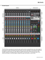
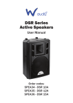
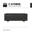
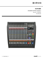
CLP1200 POWERED MIXING CONSOLE Item ref: 170.880UK User Manual Caution: Please read this manual carefully before operating Damage caused by misuse is not covered by the warranty Introduction Thank you for choosing the CLP1200 powered mixing console as part of your professional sound system. This product has been developed to provide a full arsenal of facilities and features to fulfill a comprehensive range of audio requirements with high quality, reliable results. Please read and keep this manual to achieve the best results from your purchase and avoid damage through misuse. Package Contents CLP1200 powered mixing console MPR remote control Mains lead(s) User manual If you find any accessory is missing or the product has arrived with any problems, please contact your retailer at once. This product contains no user-serviceable parts so make no attempt to try to fix or modify this item yourself as this will invalidate the warranty. We recommend you keep the original package and proof of purchase for any possible replacement or return demand. Warning To prevent the risk of fire or electric shock, do not expose any of the components to rain or moisture. If liquids are spilled on the console, stop using immediately, allow the unit to dry out and have checked by qualified personnel before further use. Avoid impact or heavy vibration to any of the components. No user serviceable parts inside - refer servicing to qualified service personnel. Safety Ensure that the correct mains lead is used with adequate current rating and that the mains voltage is as stated on the unit Avoid ingress of water or particles into any part of the housing Do not cover or obstruct cooling vents Placement Keep the console out of direct sunlight and away from heat sources. Do not place heavy objects on top of the control surface If rack-mounting, use the correct rack-ears and ensure adequate support for the weight of the product. Allow adequate space for air-flow and keep the console away from damp or dusty environments. Cleaning Use a soft dry or slightly damp cloth top clean surfaces of the console A soft brush can be used to clear debris from between controls without damaging them To avoid damage, do not use solvents to clean the components 170.880UK User Manual Console layout The CLP1200 has comprehensive input and output sections which can be split further into various stages of processing and routing. All preamps have studio grade, low noise architecture for the cleanest possible path throughout the signal chain. The input stages are repeated across each channel of the console, which simplifies operation and enables quick and easy location of various controls. The following pages of this manual are divided up into these stages to explain the details and function of each control. 170.880UK User Manual Mic/Line Input Section Channel inputs and inserts are provided as XLR and/or 6.3mm jack sockets. The connections for these inputs are assigned as follows. 1. MIC input Balanced Unbalanced 2. LINE input Balanced Unbalanced 3. Connect a balanced microphone to this XLRF input. An unbalanced microphone can be connected provided that +48V phantom power is not used. Wired as follows. Pin 1 = Ground Pin 1 = Ground Pin 2 = Signal + Pin 2 = Signal + Pin 3 = Signal – Pin 3 = Ground Connect balanced or unbalanced line level signals to this 6.3mm TRS jack input. Wired as follows. Tip = Signal + Tip = Signal + Ring = Signal – - Sleeve = Ground Sleeve = Ground Channel INSERT The channel signal can be diverted for external processing and returned back to the channel by connecting a TRS jack to 2 x mono jack lead to this connector. The channel inserts are post Low Cut but are pre-EQ. Wired as follows. TRS jack Left mono jack Right mono jack Tip = Send Tip = Send Tip = Return Ring = Return - Sleeve = Ground Sleeve = Ground Sleeve = Ground 4. +48V Phantom Press in this switch to apply +48Vdc voltage to the XLR input condenser microphones and D.I. boxes which require phantom power 5. LOW CUT Press in this switch to apply a 75Hz 18dB/oct low frequency roll-off filter which can help to reduce popping, rumble and handling noise from vocal microphones. 6. GAIN control This control trims the input signal to the optimum level for the channel strip circuitry. Too low a signal level can result in a weak signal-to-noise ratio and too high can result in overload and distortion in the signal output. The adjacent SIG and CLIP LEDs will give an indication of the signal level. Ideally, the Gain rotary control should be adjusted so that the green SIG LED is lit and the loudest passages of the input signal (e.g. bass drum beats) will just momentarily trigger the CLIP LED. Anything longer than a momentary flicker of the CLIP LED means that the Gain should be reduced. Using the PFL button further down the channel strip gives a more detailed view of the channel level on the main VU LEDs. 170.880UK User Manual Mic/Line EQ Section 7. HIGH This control can boost or cut the high frequencies (centre 12kHz) by ±15dB (12 o’clock position is zero) 8. FREQ This control sweeps the frequency band affected by the MID control with centre frequency from 100Hz through to 8kHz 9. MID This control can boost or cut the mid frequencies set using the FREQ control by ±15dB (12 o’clock position is zero) 10. LOW This control can boost or cut the low frequencies (centre 80Hz) by ±15dB (12 o’clock position is zero) Stereo Line Input Section 11. LINE L/MONO Balanced Unbalanced Connect a balanced or unbalanced line level signal to this 6.3mm TRS jack input. Wired as follows. Tip = Signal + Tip = Signal + Ring = Signal – - Sleeve = Ground Sleeve = Ground 12. LINE R For stereo line inputs, use this connector for Right input and the above connector for Left input. All following channel controls will affect both signals but Left & Right signals will remain separate. 13. ST1/PC Switches the channel input between ST1 and the PC interface Press this switch in to override the ST1 inputs and the channel will be fed from a PC or Mac connected to the USB B connector. 13. ST2/MPR Switches the channel input between ST2 and the MPR player. Press this switch in to override the ST2 inputs and the channel will be fed from playback of USB or SD media via the MPR. 14. GAIN control This control trims the mono or stereo input to the optimum level for the channel strip. Too low a signal level can result in a weak signal-to-noise ratio and too high can result in overload and distortion in the signal output. The SIG and CLIP LEDs above the rotary control give an indication of the signal level. Ideally, the Gain rotary control should be adjusted so that the green SIG LED is lit and the loudest passages of the input signal (e.g. bass drum beats) will just momentarily trigger the CLIP LED. Anything longer than a momentary flicker of the CLIP LED means that the Gain should be reduced. Using the PFL button further down the channel strip gives a more detailed view of the channel level on the main VU LEDs. 170.880UK User Manual Stereo Line EQ Section 15. HIGH EQ This control can boost or cut the high frequencies (centre 12kHz) by ±15dB (12 o’clock position is zero) 16. HIGH-MID This control can boost or cut the high-mid frequencies (2.5kHz) by ±15dB (12 o’clock position is zero) 17. LOW-MID This control can boost or cut the low-mid frequencies (250Hz) ±15dB (12 o’clock position is zero) 18. LOW This control can boost or cut the low frequencies (centre 80Hz) by ±15dB (12 o’clock position is zero) Channel Routing 19. FX POST This control governs the amount of signal from the channel routed to the DSP effects engine. If a jack is connected to the FX SEND connector (see 37 below), this will operate as an extra AUX output (POST means that it is post-fader - i.e. the signal routed to FX SEND is also affected by the channel fader level) 20. AUX POST This control governs the amount of signal from the channel routed to the AUX SEND or auxiliary output to external equipment. (POST means that it is post-fader - i.e. the signal routed to AUX SEND is also affected by the channel fader level) 21. POST / PRE Pressing this button in changes MON 1 and MON 2 outputs from POST to PRE. POST is post-fader, meaning the signals to MON 1 and MON 2 are also affected by the channel fader level. PRE is pre-fader, meaning the signals to MON 1 and MON 2 are not affected by the channel fader level. 22. MON 1 This control governs the level of signal routed to the MON 1 OUT XLR connector. The output can be used for monitoring or recording equipment. 23. MON 2 This control governs the level of signal routed to the MON 2 OUT XLR connector. The output can be used for monitoring or recording equipment. 24. PAN/BAL This control adjusts the amount of signal from the channel fed to Left or Right outputs. This varies the point in the stereo field that the signal appears. For ST1 and ST2 channels, the PAN control is replaced with a BAL control for Left/Right balance. 170.880UK User Manual Channel Faders 25. MUTE Pressing this switch in mutes the channel output (not Insert Send) A red LED indicates that the channel is muted. 26. PFL Pre-Fade Listen sends the channel signal direct to monitoring. This means that the channel signal is shown on the main VU LEDs. Also, the signal is routed directly to the headphones output. This allows the particular channel signal to be checked. If many PFLs or AFLs are selected, all are routed to monitoring. A yellow LED indicates that the channel is set to PFL. 27. Channel fader 60mm fader to adjust the channel level to the master output. A dB scale is provided to show the level of boost or cut. 12Vdc Lamp Connection At the top of the console, a 12Vdc output is provided on a BNC connection for a console lamp. This must be no more than 0.5A (6W) Master Output Section 28. MON 1 OUT Balanced XLR output for MON 1 (monitor 1) 29. MON 2 OUT Balanced XLR output for MON 2 (monitor 2) 30. MAIN L OUTPUT Balanced XLR output for main left out 31. MAIN R OUTPUT Balanced XLR output for main right out 32. FX MUTE Footswitch jack to mute FX. Connect a non-latching footswitch here to mute or un-mute the FX SEND signal 33. PHONES Stereo headphones output 34. PC INTERFACE USB type B connector for PC or Mac computer. The computer will detect the console as a USB audio device (this does not require any special software driver) which can be used to send the main mix output to PC or Mac for digital recording. This connection can also be used for audio playback from PC or Mac by pressing in the 2TK MODE button (53). Playback level is governed by the 2TK/PC control (52) 170.880UK User Manual 35. 2 TRACK INPUT Left + Right RCA connection for auxiliary input of a playback device (e.g. CD or mp3) This can be routed to ST1 or main outputs (see 54 below) and is governed by the 2TK/PC rotary level control (52) 36. 2 TRACK OUT Left + Right RCA connection for main mix output to a recording device. This output is pre-master-fader (unaffected by main Left + Right faders) 37. FX / AUX SEND Unbalanced jack outputs from FX SEND or AUX SEND routes. The mix is governed by FX and AUX levels from each channel. 38. PW AMP L+R Left + Right 6.3mm jack inputs to the main power amp section. This enables the CLP1200 to be used purely as a power amplifier without the mixer section. In addition, connecting MAIN OUTPUTS (30, 31) as a stereo send and using the PW AMP inputs as a stereo return allows external processing equipment to be patched in (or inserted) before the power amplifier section. MPR Media Player/Recorder 39. SD card slot Insert SD or SDHC card with compressed audio files here 40. USB port Insert USB storage device with compressed audio files here 41. IR receiver Receiver for MPR remote 42. MPR controls Transport and recording controls for MPR section as shown below Press briefly for previous track. Press and hold for reverse search Press briefly for next track. Press and hold for forward search Press to record main output to media Press to play or pause current track 43. Display Digital display with track and play status information 44. MPR LEVEL Rotary output level control for media player/recorder 45. MPR Route ST2 - L/R MPR Route select. If not pressed in, the MPR output is routed through ST2 channel 170.880UK User Manual Remote Control for MPR Media Player/Recorder The MPR module is supplied with an infra-red handheld remote control to handle some of the onboard controls away from the console. Before use, it is necessary to pull out the clear tab at the base of the handset to engage the battery. This remote control is most effective in line of sight with the “IR” receiver on the MPR window. Key assignments are detailed on the diagram shown here. Graphic Equalizer The main EQ is an illuminated stereo 9-band graphic equalizer with built-in feedback detection and can be assigned to main output or monitors. This offers refined audio spectrum shaping and feedback control for live mic situations. 46. EQ sliders. Each slider controls a boost or cut of up to 12dB centred at the specified frequency with an LED to aid visibility in dark situations. 47. Feedback Detection Press in to engage the feedback detection circuit. All slider LEDs Will be dimmed until feedback is detected and then the band within which the feedback is detected will illuminate brightly. Move this fader down to reduce or eliminate the risk of feedback at that frequency. 48. L/R MON1-2 The graphic equalizer is normally assigned to main left & right outputs but pressing this button in will assign it to monitor 1 and monitor 2 outputs instead. This gives the option of EQ and feedback control for monitors instead of main outputs. 49. EQ OUT/IN When this button is pressed in, the graphic equalizer is in operation and the slider LEDs will be lit. When the button is out, it is not in operation and the slider LEDs will be off. 170.880UK User Manual Master Routing Section 50. FX SEND Overall level control of signals routed to the FX Send buss, either for internal DSP or FX Send output (37). When using the internal DSP, it is important to observe the LED level meter on the DSP section (56) and if the signal is clipping (red LED lighting) to reduce the FX SEND level accordingly. 51. AUX SEND Overall level control of signals routed to the AUX Send output (37) 52. 2-TK/PC Output level control for the 2 track RCA inputs (35) or stereo input from the PC interface (34) 53. 2-TK/PC MODE REC/PLAY When not pressed in, the main output is routed digitally to the PC interface for recording to PC or Mac computer. Pressing this button reverses this by routing the output of the PC or Mac back to the PC interface for playback. 54. 2-TK/PC ROUTE 2-track/PC route. Normally, playback from the PC interface is routed via ST1 channel. ST1 - L/R Press this button in to route playback directly to main outputs via 2TK/PC control (52) 55. PHONES LEVEL Level control for headphones output. DSP Effects Engine The CLP1200 has an internal 24-bit DSP processor for audio effects, as detailed on the DSP Table (next page) 56. 6-segment LED input level meter. Indicates overall input level to DSP 57. LED numerical display. Indicates selected program (see table below) 58. TAP Press once to switch the rotary control (59) to PARAMETER 2. Tap rhythmically more than twice to set a tempo for time effects 59. PROGRAM/PARAMETER Turn this rotary encoder to select a program. The numerical display will flash the selected program number. Press the encoder to confirm the selection and the display will stop flashing and the selected program will be active. Press the encoder again and a dot will appear in the display indicating PARAMETER 1. Turning the encoder will change PARAMETER 1 for the selected program as detailed in the DSP Table on the next page. Pressing the TAP button (58) will switch to PARAMETER 2 and then turning the encoder will change PARAMETER 2 for the selected program. These parameter changes are stored for when the program is selected in future. 60. EFF TO MAIN L/R Press this button to send the output of the DSP to the main L + R via the FX fader (64) 61. EFF TO MON Press this button to send the output of the DSP to MON1 & MON2 via the FX fader (64) 170.880UK User Manual 170.880UK User Manual Status Indicators The master section has 4 status LEDs, which indicate as follows. POWER PFL/AFL LIMIT PROTECT When lit, this indicates that the main power is on Pre-Fade or After-Fade Listen is active when lit Amplifier output clip limiter is active when lit Amplifier protection is active when lit The amplifier is not operational when in protect mode, which indicates that a fault is detected. Main Output Level Meters The main output level meters comprise a pair of volume ladders with 15 LEDs in each. These normally display the main left and right output levels unless PFL or AFL is active. When one or more PFL or AFL buttons are pressed in, these ladders will show the output of that channel (or those channels) directly. This enables more detailed analysis of the signal level than can be shown by the channel signal and clip LEDs alone. When monitoring any signal levels, it is important to prevent the red LEDs from lighting for anything longer than a brief flicker. Persistent lighting of the red LEDs indicates clipping or distortion. Master Fader Section The master fader section controls output level for monitors 1 + 2, DSP and main L + R outputs. 62. MUTE Press to mute the relative output(s) A red LED lights when muted. 63. PFL / AFL Activates Pre-Fader Listen for monitor outputs or After-Fader Listen for DSP Effects.The output of either is routed to the headphones (33) output and displayed on the main level meters (see PFL section above) A yellow LED lights when active 64. Faders Output level 60mm fader controls for Monitors 1 + 2, Effects and Main L + R Decibel markings (dB) give a reference to the level setting applied. 170.880UK User Manual Rear Panel 65. Combined IEC mains inlet, fuse holder and switch. Connect the IEC inlet (65) to mains power using the supplied mains lead. In case of the fuse blowing, replace only with the type indicated. If the fuse is repeatedly blowing, refer to qualified service personnel The illuminated rocker switch activates mains power to the unit. 66. 67. 68. 69. Cooling fan. Do not block or cover the cooling fan vents and avoid any objects entering into the housing. Right speaker output. Left speaker output. Cooling fan. Do not block or cover the cooling fan vents and avoid any objects entering into the housing. Connecting Speakers When connecting speakers to the CLP1200, ensure that the combined load for each output (left or right) is no lower than 4 Ohms (4Ω). To make sure of this, check the speaker manufacturer’s information. If connecting more than one speaker to an output channel, observe the following calculation method. Note: normally, speakers will be connected in parallel by connecting a speaker lead from one to another. Most PA and sound reinforcement speakers are 8Ω, so we consider that 1/8 + 1/8 = 1/4. Therefore, when connecting 2 x 8Ω speakers together in parallel, the resulting total load is 4Ω. It is also important to ensure that the power delivered to the speakers will not overload them. The CLP1200 will deliver 600Wrms per channel at 4Ω or 400Wrms per channel at 8Ω. An 8Ω speaker connected on its own to an output channel must be able to handle 400Wrms. A 4Ω speaker connected on its own to an output channel must be able to handle 600Wrms When connecting 2 x 8Ω speakers to a single output channel, they will share the 600W output equally. Therefore, it is important that they can handle 300Wrms each. 170.880UK User Manual Specifications Power supply Fuse rating Power consumption Phantom power Input level : Mic Input level : Line Output level Frequency response CMRR THD Crosstalk Signal to noise ratio Low-cut filter High EQ Mic Mid Low High High-mid EQ Line Low-mid Low EQ Master EQ Master bands Effects USB/SD player USB computer interface Headphone output Output power @ 4 ohms Output power @ 8 ohms Dimensions Weight 230Vac, 50/60Hz (IEC) T10AL 250V 1000W (max.) +48V individually switchable to XLR inputs +22dBu (max.) +20dBu (max.) +28dBu (main), +22dBu (mon/aux) 20Hz - 30kHz (+/-1dB) >70dB typical @1kHz (mic) <0.005% (mic to main out) >89dB @ 1kHz -86dB (unity gain) 75Hz, 18dB/oct (mic/line channels) 12kHz shelving (+/-15dB) 100Hz-8kHz swept band pass (+/-15dB) 80Hz shelving (+/-15dB) 12kHz shelving (+/-15dB) 2.5kHz band pass (+/-15dB) 250Hz band pass (+/-15dB) 80Hz shelving (+/-15dB) 9-band graphic with feedback detection 63, 125, 250, 500Hz, 1k, 2k, 4k, 8k, 16kHz 16 preset, 24-bit DSP, 40khz MPR player/recorder with IR remote Type B duplex PC/Mac (16bit, 48kHz) plug & play Stereo 6.3mm jack (30-600 Ohms recommended) 2 x 600Wrms 2 x 400Wrms 185 x 497 x 490mm 17.72kg 170.880UK User Manual Troubleshooting No power LED on control panel Power LED is on but no other LEDs and no output Power light and VU LEDs lighting but no speaker output No output from stereo inputs No playback from USB or SD media No playback from PC interface No signal from PC interface to computer VU LEDs do not show MAIN output levels Graphic EQ has no effect on MAIN outputs Output is very loud or distorted Output is working but at very low level Feedback (loud squealing or howling from mics) Ensure mains outlet voltage is correct for the unit Check power is switched on at the rear panel Check IEC fuse – if blowing fuses, refer to qualified service personnel Check input signals and condition of connection leads Check GAIN is not too low on channel input Check channel fader, GAIN and EQ controls are not turned fully down Check MASTER faders are not fully down Check that channels or outputs are not muted. When using condenser microphones, check that +48V phantom is on. (Turn down all faders before switching on) Check that PFL/AFL buttons are all switched out Check that all Graphic EQ sliders are not fully down For digital media, check that files are standard compressed format For PC or MPR digital audio inputs, check signal routing Check output connections to speakers Check that speakers are in good working order Check that Main L+R outputs are not muted Check MASTER faders are not fully down Disconnect any leads from Power Amp inputs and re-check Check that PC or MPR routing are not switched in Check that stereo channels are not muted Check that stereo channel faders are not fully down Check that files are standard compressed audio format Check routing option for MPR section, switch to main L/R Check MPR level and/or ST2 level controls Check that computer is set to output to the CLP1200 USB audio device Check that computer has installed the CLP1200 as a USB audio device Check PC Mode and PC Route buttons are set for playback If routed through ST1 channel, check mute and levels Check that computer has installed USB audio device Check PC Mode button is set to Record Check computer has USB audio device set as input source Check that PFL/AFL buttons are all switched out Check L/R - MON1-2 button is not pressed in Check that EQ IN button is pressed in Check level of input signal is not too high Reduce channel GAIN and EQ settings Reduce channel and MAIN faders levels Ensure Hi-Z line level input(s) not connected via XLR Check output levels of equipment connected via channel inserts Check AUX and DSP level controls and reduce if necessary Check input gain level on recorder or recording software Check input audio source level is not too low Ensure low impedance line or mic signal is not connected via jack Increase channel GAIN control and EQ settings if turned down Increase channel and MAIN faders levels Check input gain level on recorder or recording software Face microphone away from speakers and monitors Reduce channel GAIN level and EQ level(s) Reduce AUX and/or EFFECT levels Reduce channel and/or MAIN fader levels Engage Feedback Detention & reduce anyproblem frequencies 170.880UK User Manual Disposal: The “Crossed Wheelie Bin” symbol on the product means that the product is classed as Electrical or Electronic equipment and should not be disposed with other household or commercial waste at the end of its useful life. The goods must be disposed of according to your local council guidelines. Errors and omissions excepted. Copyright© 2013. AVSL Group Ltd. 170.880UK User Manual