1
DRAFT FOR DEVELOPMENT
Explosives for civil
uses — Detonators
and relays —
Part 27: Definitions, methods and
requirements for electronic initiation
systems
ICS 71.100.30
12&23<,1*:,7+287%6,3(50,66,21(;&(37$63(50,77('%<&23<5,*+7/$:
DD CEN/TS
13763-27:2003
DD CEN/TS 13763-27:2003
National foreword
This Draft for Development is the English language version of
CEN/TS 13763-27:2003.
This publication is not to be regarded as a British Standard.
It is being issued in the Draft for Development series of publications and is of
a provisional nature because electronic initiation systems are a recent
innovation and the testing procedures are not fully developed. It should be
applied on this provisional basis, so that information and experience of its
practical application may be obtained.
Comments arising from the use of this Draft for Development are requested so
that UK experience can be reported to the European organization responsible
for its conversion into a European Standard. A review of this publication will
be initiated 2 years after its publication by the European organization so that
a decision can be taken on its status at the end of its three-year life. The
commencement of the review period will be notified by an announcement in
Update Standards.
According to the replies received by the end of the review period, the
responsible BSI Committee will decide whether to support the conversion into
a European Standard, to extend the life of the Technical Specification or to
withdraw it. Comments should be sent in writing to the Secretary of BSI
Technical Committee CII/61, Explosives for civil uses, at 389 Chiswick High
Road, London W4 4AL, giving the document reference and clause number and
proposing, where possible, an appropriate revision of the text.
A list of organizations represented on this committee can be obtained on
request to its secretary.
Cross-references
The British Standards which implement international or European
publications referred to in this document may be found in the BSI Catalogue
under the section entitled “International Standards Correspondence Index”, or
by using the “Search” facility of the BSI Electronic Catalogue or of British
Standards Online.
This Draft for Development
was published under the
authority of the Standards
Policy and Strategy Committee
on 10 September 2003
Summary of pages
This document comprises a front cover, an inside front cover, the ENV title
page, pages 2 to 49 and a back cover.
The BSI copyright date displayed in this document indicates when the
document was last issued.
Amendments issued since publication
Amd. No.
© BSI 10 September 2003
ISBN 0 580 42591 6
Date
Comments
TECHNICAL SPECIFICATION
SPÉCIFICATION TECHNIQUE
TECHNISCHE SPEZIFIKATION
CEN/TS 13763-27
July 2003
ICS 71.100.30
English version
Explosives for civil uses – Detonators and relays – Part 27:
Definitions, methods and requirements for electronic initiation
systems
Explosifs à usage civil – Détonateurs et relais – Partie 27:
Définitions, méthodes et exigences relatives aux systèmes
d’amorçage électronique
Explosivstoffe für zivile Zwecke – Zünder und
Verzögerungselemente – Teil 27: Definitionen, Verfahren
und Anforderungen an elektronische Zündsysteme
This Technical Specification (CEN/TS) was approved by CEN on 19 December 2002 for provisional application.
The period of validity of this CEN/TS is limited initially to three years. After two years the members of CEN will be requested to submit their
comments, particularly on the question whether the CEN/TS can be converted into a European Standard.
CEN members are required to announce the existence of this CEN/TS in the same way as for an EN and to make the CEN/TS available. It
is permissible to keep conflicting national standards in force (in parallel to the CEN/TS) until the final decision about the possible
conversion of the CEN/TS into an EN is reached.
CEN members are the national standards bodies of Austria, Belgium, Czech Republic, Denmark, Finland, France, Germany, Greece,
Hungary, Iceland, Ireland, Italy, Luxembourg, Malta, Netherlands, Norway, Portugal, Slovakia, Spain, Sweden, Switzerland and United
Kingdom.
EUROPEAN COMMITTEE FOR STANDARDIZATION
COMITÉ EUROPÉEN DE NORMALISATION
EUROPÄISCHES KOMITEE FÜR NORMUNG
Management Centre: rue de Stassart, 36
© 2003 CEN
All rights of exploitation in any form and by any means reserved
worldwide for CEN national Members.
B-1050 Brussels
Ref. No. CEN/TS 13763-27:2003 E
CEN/TS 13763-27:2003 (E)
Contents
Page
Foreword......................................................................................................................................................................3
0
Introduction ....................................................................................................................................................5
1
Scope ..............................................................................................................................................................9
2
Normative references ....................................................................................................................................9
3
Terms and definitions..................................................................................................................................10
4
Procedure .....................................................................................................................................................12
5
Test report ....................................................................................................................................................36
6
Requirements ...............................................................................................................................................36
Annex A (informative) Examples of hazards and faults ........................................................................................37
Annex B (informative) Information on evaluation techniques ..............................................................................44
Annex C (informative) Proposals for the detonator fusehead replaced (dummy detonators) ..........................46
Annex D (informative) Determination of resistance to dynamic pressure ..........................................................48
Bibliography ..............................................................................................................................................................49
2
CEN/TS 13763-27:2003 (E)
Foreword
This document (CEN/TS 13763-27:2003) has been prepared by Technical Committee CEN/TC 321 "Explosives for
civil uses", the secretariat of which is held by AENOR.
This document includes a Bibliography.
Annexes A, B, C and D are informative.
This Technical Specification is one of a series of standards with the generic title Explosives for civil uses –
Detonators and relays. The other parts of this series are listed below:
prEN 13763-1
Part 1: Requirements
EN 13763-2 Part 2: Determination of thermal stability
EN 13763-3 Part 3: Determination of sensitiveness to impact
prEN 13763-4
Part 4: Determination of resistance to abrasion of leading wires and shock tubes
prEN 13763-5
Part 5: Determination of resistance to cutting damage of leading wires and shock tubes
prEN 13763-6
Part 6: Determination of resistance to cracking in low temperatures of leading wires
prEN 13763-7
Part 7: Determination of the mechanical strength of leading wires, shock tubes, connections,
crimps and closures
prEN 13763-8
Part 8: Determination of resistance to vibration of plain detonators
prEN 13763-9
Part 9: Determination of resistance to bending of detonators
prEN 13763-10
Part 10: Method for the determination of resistance to torsion of sealing plugs
prEN 13763-11
Part 11: Determination of resistance to damage by dropping of detonators and relays
prEN 13763-12
Part 12: Determination of resistance to hydrostatic pressure
prEN 13763-13
Part 13: Determination of resistance of electric detonator to electrostatic discharge
prEN 13763-14
Part 14: Determination of resistance of electric detonator to the influence of radio frequency
radiation
prEN 13763-15
Part 15: Determination of equivalent initiating capability
prEN 13763-16
Part 16: Determination of delay accuracy
prEN 13763-17
Part 17: Determination of no-fire current of electric detonators
prEN 13763-18
Part 18: Determination of series firing current of electric detonators
prEN 13763-19
Part 19: Determination of firing pulse of electric detonators
prEN 13763-20
Part 20: Determination of total resistance of electric detonators
prEN 13763-21
Part 21: Determination of flash-over voltage of electric detonators
3
CEN/TS 13763-27:2003 (E)
prEN 13763-22
Part 22: Determination of capacitance, insulation resistance and insulation breakdown of leading
wires
EN 13763-23 Part 23: Determination of the shock-wave velocity of shock tube
EN 13763-24 Part 24: Determination of the non-conductivity of shock tube
prEN 13763-25
Part 25: Determination of transfer capacity of relay and coupling accessories
prEN 13763-26
Part 26: Definitions, methods and requirements for devices and accessories for reliable and safe
function of detonators and relays.
According to the CEN/CENELEC Internal Regulations, the national standards organizations of the following
countries are bound to announce this CEN Technical Specification: Austria, Belgium, Czech Republic, Denmark,
Finland, France, Germany, Greece, Hungary, Iceland, Ireland, Italy, Luxembourg, Malta, Netherlands, Norway,
Portugal, Slovakia, Spain, Sweden, Switzerland and the United Kingdom.
4
CEN/TS 13763-27:2003 (E)
0 Introduction
0.1 Background and basic principles
Electronic initiation systems have been developed for use in civil blasting work. Detonators in these systems
normally have delay times which are far more accurate than conventional detonators with pyrotechnic delay, and
are claimed to facilitate better blasting results, e.g. in terms of better fragmentation, reduced ground vibrations, less
damage on remaining rock, etc.
From a safety and reliability point of view electronic initiation systems are more complex than conventional electric
and non-electric detonator systems, which results in new risk factors.
The aim of this Technical Specification is to reach negligible risks at least at the same applied safety and reliability
level as the corresponding standards for conventional electric detonators. This statement should be seen as a
general objective of the Technical Specification at a system level and not as a detailed guideline to judge the level
of acceptability for individual specific demands. However in some cases the standards for conventional electric
detonators referred to in this Technical Specification are applicable in various grades. In these cases the
requirement level for electric detonators have been adopted, possibly after some amendments if necessary.
This Technical Specification specifies a risk analysis procedure to be used to investigate the safety and reliability of
electronic initiation systems by identifying hazards and estimating the risks associated with the system.
The step in the risk analysis procedure, which refers to acceptability of risks, includes both references to testing
and evaluation methods, which apply where appropriate for the specific system. The Technical Specification also
stipulates levels of acceptability.
This structure of combining a general risk analysis procedure in combination with specific requirements related to
testing and evaluation as well as guidelines for evaluation specified in informative annexes has been chosen for the
following reasons:
• The use of electronic initiation systems are highly related to safety of human life and health as well as to
property. The safety and reliability of electronic initiation systems depends on a number of factors interacting,
which makes the systems complicated to evaluate in these respects. In this Technical Specification relevant risk
factors have been addressed to risks of unintended initiation, misfire and incorrect function.
• The need to consider safety and reliability for individual components of the system i.e. detonators,
firing/testing/programming units as well as overall system aspects including connection and set-up limits and
communication between the different components.
• The need for evaluation of safety-critical electronic hardware and software both in detonators and in
firing/testing/programming units.
• Manufacturers of electronic initiation systems have used significantly different design and system solutions in
order to fulfil acceptable safety and reliability criteria. The product development in the field is rapid. Therefore
the Technical Specification aims to be valid for different system solutions.
Considerable effort has been taken to refer to other parts of prEN 13763 for conventional detonators as far as
possible, specifying applicability of these tests as well as possible amendments in order to avoid redundancy and
inconsistency.
5
CEN/TS 13763-27:2003 (E)
Possibilities for non-destructive testing using dummy detonators without explosive content, have been considered
as far as possible due to the high costs of electronic detonators.
0.2 Overview of an electronic initiation system
Electronic detonator systems can be fitted in two categories: non-programmable electronic detonators (or fixed
delay detonators) and programmable delay detonators. Programmable detonators can be programmed using oneway data communication or two-way data communication. These categories are elaborated upon below:
Non-programmable detonators
This type of detonator does not require any data communications in order to ignite. The connection to the detonator
can be electrical or non-electrical. These detonators are normally numbered in such a way that the user recognizes
its intended delay time.
Programmable detonators
The delay time of these detonators is programmed prior to blasting, by either the testing unit or the firing unit. This
type of detonators usually require electrical connections to facilitate:
•
One-way data communication: This implies that communication only take place to the detonator. No
information is received from the detonator. In these systems, it is vitally important that communications to the
detonator are robust.
•
Two-way data communication: Communication takes place in both directions. Since feedback is received
from the detonator, it is possible to establish the state of the detonator. Useful information can include integrity
of the communications to the detonator, integrity of the initiation element, the firing capacitor voltage, results of
a self-test, etc.
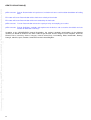
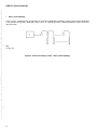
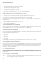
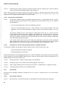
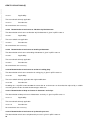
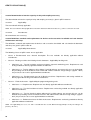
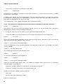
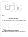
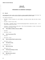
0.3 Block diagram of a generic two wire programmable electronic detonator
Not all components illustrated below are necessarily required in an electronic detonator, at the same time, some
components may have been omitted. The purpose of the diagram is to familiarize the reader of this document with
some of the functions and components of an electronic detonator, such that the requirements and implications for
safe operations may be better understood.
6
CEN/TS 13763-27:2003 (E)
Key
1
Communication line
B Full wave rectifier to make the system polarity insensitive (optional)
C1 Power supply capacitor
C2 Firing capacitor. This capacitor supplies the energy required to fire the initiation element (IE). This capacitor may be
disconnected and/or shorted prior to blasting with the aid of SW1 and SW2. C1 and C2 may be separate capacitors, or they
may be combined. SW3 will be closed at the time of firing, after C2 had enough energy stored.
Figure 1 – Block diagram of a generic 2-wire programmable electronic detonator
The components illustrated above may be integrated into one or more monolithic circuits.
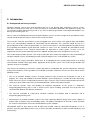
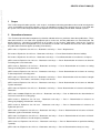
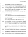
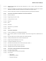
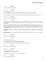
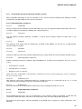
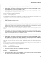
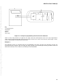
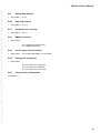
0.4 Electrical wiring systems
This section refers only to electrical connections. Even though other wiring system may exist, the two most
common topologies are:
•
Bus topology
Each detonator is connected to a common and separate ”surface“ wire. Usually, a connector is used per detonator.
Key
1 Firing unit
2 Connectors
3 Detonators
4 Surface wire
Figure 2 – Electrical wiring systems - Bus topology
7
CEN/TS 13763-27:2003 (E)
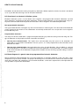
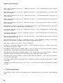
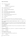
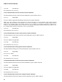
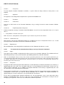
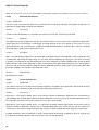
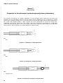
•
Daisy chain topology
In this system, a detonator has enough wire to reach the neighbouring detonator, and the tail of the one detonator
is connected to the previous detonator. There is thus no separate bus wire. A detonator would usually have one or
two connectors.
Key
1 Firing unit
Figure 3 - Electrical wiring systems - Daisy chain topology
8
CEN/TS 13763-27:2003 (E)
1
Scope
This Technical Specification specifies a risk analysis, evaluation and testing procedure to be used to investigate the
safety and reliability of electronic initiation systems by identifying hazards and estimating the risks associated with
the system. The Technical Specification also stipulates levels of acceptability for electronic initiation systems.
2
Normative references
This Technical Specification incorporates by dated or undated reference, provisions from other publications. These
normative references are cited at the appropriate places in the text, and the publications are listed hereafter. For
dated references, subsequent amendments to or revisions of any of these publications apply to this Technical
Specification only when incorporated in it by amendment or revision. For undated references the latest edition of
the publication referred to applies (including amendments).
prEN 13763-1; Explosives for civil uses - Detonators and relays — Part 1: Requirements.
EN 13763-2; Explosives for civil uses - Detonators and relays — Part 2: Determination of thermal stability.
EN 13763-3; Explosives for civil uses - Detonators and relays — Part 3:Determination of sensitiveness to impact.
prEN 13763-4; Explosives for civil uses - Detonators and relays — Part 4: Determination of resistance to abrasion
of leading wires and shock tubes.
prEN 13763-5; Explosives for civil uses - Detonators and relays — Part 5: Determination of resistance to cutting
damage of leading wires and shock tubes.
prEN 13763-6; Explosives for civil uses - Detonators and relays — Part 6: Determination of resistance to cracking
in low temperatures of leading wires.
prEN 13763-7; Explosives for civil uses - Detonators and relays — Part 7: Determination of the mechanical strength
of leading wires, shock tubes, connections, crimps and closures.
prEN 13763-8; Explosives for civil uses - Detonators and relays — Part 8: Determination of resistance to vibration
of plain detonators.
prEN 13763-9; Explosives for civil uses - Detonators and relays — Part 9: Determination of resistance to bending of
detonators.
prEN 13763-10:2000; Explosives for civil uses - Detonators and relays — Part 10: Method for the determination of
resistance to torsion of sealing plugs.
prEN 13763-11; Explosives for civil uses - Detonators and relays — Part 11: Determination of resistance to
damage by dropping of detonators and relays.
prEN 13763-12; Explosives for civil uses - Detonators and relays — Part 12: Determination of resistance to
hydrostatic pressure.
prEN 13763-13; Explosives for civil uses - Detonators and relays — Part 13: Determination of resistance of electric
detonators against electrostatic discharge.
prEN 13763-14; Explosives for civil uses - Detonators and relays — Part 14: Determination of resistance of electric
detonators to the influence of radio frequency radiation.
prEN 13763-15; Explosives for civil uses - Detonators and relays — Part 15: Determination of equivalent initiating
capability.
prEN 13763-16; Explosives for civil uses - Detonators and relays — Part 16: Determination of delay accuracy.
9
CEN/TS 13763-27:2003 (E)
prEN 13763-17; Explosives for civil uses - Detonators and relays — Part 17: Determination of no-fire current of
electric detonators.
prEN 13763-18; Explosives for civil uses - Detonators and relays — Part 18: Determination of series firing current
of electric detonators.
prEN 13763-19; Explosives for civil uses - Detonators and relays — Part 19: Determination of firing pulse on
electric detonators.
prEN 13763-20; Explosives for civil uses - Detonators and relays — Part 20: Determination of total resistance of
electric detonators.
prEN 13763-21; Explosives for civil uses - Detonators and relays — Part 21: Determination of flash-over voltage of
electric detonators.
prEN 13763-22; Explosives for civil uses - Detonators and relays — Part 22: Determination of capacitance,
insulation resistance and insulation breakdown of leading wires.
EN 13763-23; Explosives for civil uses - Detonators and relays — Part 23: Determination of the shock-wave
velocity of shock tubes.
EN 13763-24; Explosives for civil uses - Detonators and relays — Part 24: Determination of the electrical nonconductivity of shock tubes.
prEN 13763-25; Explosives for civil uses - Detonators and relays — Part 25: Determination of transfer capacity of
relay and coupling accessories.
prEN 13763-26; Explosives for civil uses - Detonators and relays — Part 26: Definitions, methods and requirements
for devices and accessories for reliable and safe function of detonators and relays.
prEN 13857-1; Explosives for civil uses — Part 1: Terminology.
EN 60870-5-1; Telecontrol equipment and systems — Part 5: Transmission protocols — Section 1: Transmission
frame formats (IEC 60870-5-1:1990).
EN 61000-4-3; Electromagnetic compatibility (EMC) — Part 4-3: Testing and measurement techniques. Radiated,
radio-frequency, electromagnetic field immunity test (IEC 61000-4-3:2002).
EN 61000-4-6; Electromagnetic compatibility (EMC) — Part 4: Testing and measurement techniques — Section 6:
Immunity to conducted disturbances, induced by radio-frequency fields (IEC 61000-4-6:1996).
EN 61496-1:1997; Safety of machinery – Electro-sensitive protective equipment — Part 1: General requirements
and tests (IEC 61496-1:1997)
EN ISO/IEC 17025; General requirements for the competence of testing and calibration laboratories (ISO/IEC
17025:1999).
IEC 60068-2-14; Environmental testing — Part 2: Tests - Test N: Change of temperature (IEC 60068-2-14:1984 +
A1:1986).
3
Terms and definitions
For the purposes of this Technical Specification the terms and definitions given in prEN 13857-1 and the following
apply.
10
CEN/TS 13763-27:2003 (E)
3.1
electronic initiation system
system generally composed of a firing unit and/or a testing unit and/or a programming unit, and a certain number of
electronic detonators
3.2
electronic detonator
electronic detonator as defined in prEN13857-1
3.3
non programmable electronic detonator
electronic detonator with a programmed delay time. This programmation is made by the manufacturer.
3.4
pre-programmed electronic detonator
electronic detonator with a pre programmed delay number programmed by the manufacturer. The firing time of
these detonators is a multiple of this delay number and is determined on the field.
3.5
programmable electronic detonator
electronic detonator of which the functioning delay time is programmable, on the field, by mean of a programming
unit and/or a firing unit
3.6
firing unit
apparatus used in an electronic initiation system to initiate a blast. Such a device can control and/or program
and/or test the electronic detonators and charge the firing capacitor of the electronic detonators before the initiation
of the blast. This device can be driven by a computer.
3.7
testing unit
field tester intended, in an electronic initiation system, to test the electronic detonators and/or the initiating circuit.
This tester should not be able to initiate the electronic detonator.
3.8
programming unit
apparatus used, on the field, to program a delay time and/or an address to a programmable electronic detonator.
This apparatus can also test the electronic detonator. This apparatus should not be able to initiate the electronic
detonator.
3.9
electronic initiation system using no data communication
electronic initiation system in which the electronic detonator receives only firing energy from the firing unit (e.g. by
non-electric or electric means)
3.10
electronic initiation system using one way data communication
electronic initiation system in which the electronic detonator may receive commands from the programming/testing
unit and/or from firing unit but cannot send back any information to PROGRAMMING/TESTING and/or to firing unit
3.11
electronic initiation system using two way data communication
electronic initiation system in which the electronic detonator may receive commands from the programming/testing
unit and/or to firing unit and send back information to PROGRAMMING/TESTING and/or from firing unit
3.12
critical defect
defect that, according to judgement and experience, is likely to result in hazardous or unsafe conditions for
individuals using, maintaining or depending upon the considered product; or that is likely to prevent performance of
the function of a major end item e.g. an unintended initiation caused during transport, storage and handling
11
CEN/TS 13763-27:2003 (E)
3.13
major defect
defect, other than critical, that is likely to result in failure, or to reduce materially the usability of the considered
product for its intended purpose, e.g. misfire of more than one detonator in a blasting round
3.14
minor defect
defect that is not likely to reduce materially the usability of the considered product for its intended purpose, or that
is a departure from established specifications having little bearing on the effective use or operation of this product,
e.g. misfire of one single detonator or incorrect function (delay time) of a detonator
NOTE The above defect criteria are specific to electronic initiation systems and apply to all components of the system.
3.15
fault
state of an entity characterized by the inaptitude to achieve an intended function
3.16
failure
suspension of the aptitude of an entity to achieve a necessary function. After a failure, the entity is in fault.
3.17
independent circuits
two circuits are independent if they are physically separated and if a failure of one circuit cannot put the second
one in fault
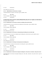
4
Procedure
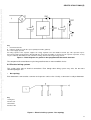
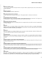
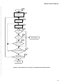
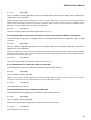
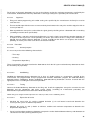
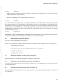
4.1 General (step 1 of Figure 4)
The risk analysis, evaluation and testing procedure, as described in 4.2 to clause 5 and illustrated in the flow
diagram given in Figure 4.
12
CEN/TS 13763-27:2003 (E)
Step 1
Start
Step 2
Identify qualitative and
quantitative
characteristics (4.2)
Step 3
Identify possible
hazards (4.3)
Estimate risk for
each hazard (4.4)
Step 4
Step 5
Is risk
acceptable?
(4.5)
no
yes
Step 6
Is risk
reduced?
(4.6)
yes
yes
Report risk analysis.
Action required
no
Step 7
Other hazards
generated? (4.7)
no
Step 8
no
Are all identified
hazards evaluated? (4.8)
yes
no
Step 9
Are all hazards
identified? (4.9)
yes
Report risk
analysis (5)
Figure 4 - Flow diagram of risk analysis, evaluation and testing procedure
13
CEN/TS 13763-27:2003 (E)
4.2 Identification of qualitative and quantitative characteristics
system (step 2 of Figure 4)
related to electronic initiation
The information in this step shall be provided by the manufacturer of the electronic initiation system to the body
responsible for carrying out the risk analysis procedure described in this Technical Specification.
For the particular electronic initiation system or accessory being considered, list all those characteristics that can
affect its safety and reliability.
NOTE The following list exemplifies questions to be answered, if relevant for the system, in drawing up such a list:
a) What is the intended use and how is the electronic initiation system to be used?
The following factor shall be considered:
• During which phases of normal operation is the operator potentially exposed to risks?
b) How is the system designed?
• Complete design drawings provided by the manufacturer.
c) Which devices and accessories are included in the system?
Description, principles and intended application (on the blast site, only in safe area, etc.) of e.g.:
• Programming units
• Testing units
• Firing units
d) Which functions are provided by the system?
• General functions
• Safety functions
• Reliability functions
• Time out functions (detonator, firing/testing/programming units)
• Possibilities to abort the blasting sequence
• Programming functions
• Calibration function (e.g. for delay accuracy)
• Self-check functions (e.g. start up check, run-time check of device and detonator, information transfer and
storing; detonator timer operation, fusehead, voltage level, capacitor level, error handling)
• Limits for safe functioning
• Output strength of detonator
14
CEN/TS 13763-27:2003 (E)
e) Which design measures have been taken to obtain necessary safety and reliability?
• Safety - fault tolerance measures, safety against two independent faults
• Reliability - fault tolerance measures, safety against one fault
• Can relevant failures be detected before a possible hazard occurs?
f) To which environmental stresses will the system be subjected during transport, storage and use?
• Climatic environment (temperature, humidity, hydrostatic pressure)
• Mechanical environment (static and dynamic)
• Electrical environment (e.g. electrostatic discharge, electromagnetic radiation).
• Shelf life limits
g) Which communication principles between detonators and system devices or accessories are used?
• No data communication or one way/two way data communication. Which information is transmitted/received?
• Coding principles for communication
• Delay of the detonator depending on the connection order?
• Is the function depending on intact communication and wiring during the whole blasting sequence or is the
detonator self-contained after receiving the initiation command?
• Number of wires on the bus (information carrier for the different wires)
h) Which output energy is provided from the output of firing/programming/testing units?
• Voltage
• Current
• Energy (pulse lengths)
• Limits for safe functioning of detonator (e.g. battery level, bus wire length)
i) Which energy source is used to initiate the detonator?
• Electrical energy (fusehead characteristics, e.g. no fire current/voltage, all fire current/voltage)
j) Is energy stored inside the detonator?
• Time limits for safe functioning
• Self discharge principles (at interrupted firing sequence, at disconnection from the wiring bus, comparison with
longest available delay time)
k) Do the different devices contain software?
•
Programming language and compiler/linker used
15
CEN/TS 13763-27:2003 (E)
•
Memory storage principles, both variable and unvariable
•
Description of safety related program modules
•
Description of self-monitoring measures made
•
Manufacturer specified circuits (e.g. PAL, PLA, PLD, CPLD, FPGA or ASIC’s)
l) Which safety measures have been considered in case of misuse?
• Use of device/accessory for electronic initiation system with conventional electric detonator
• Use of device/accessory for conventional electric detonators with electronic detonator
NOTE Furthermore information on marking principles may be required due to national regulations, e.g. marking in respect of
identifying detonators:
• Marking at production (sequence number, delay time, etc)
• Manual marking after programming
4.3 Hazard identification (step 3 of Figure 4)
Compile a comprehensive list of potential hazards associated with the electronic initiation system in both normal
and fault conditions. Clause A.1 can be used as a list of examples of potential hazards.
4.4 Risk estimation (step 4 of Figure 4)
For each of the possible hazards identified under 4.3, estimate the risks in both normal and fault conditions using
available information/data and address them to:
• Critical defect
• Major defect
• Minor defect
Several methods are available for the systematic analysis of hazards. Examples are given in annex B.
4.5 Acceptability of risk (step 5 of Figure 4)
Evaluate and test that a risk for a given hazard is appropriately addressed by compliance with a relevant standard
or method as described in 4.5.1 to 4.5.6 below. If the risk for a given hazard estimated in accordance with 4.4
exceeds the levels of acceptability defined through the application of relevant standards or by other means,
proceed to 4.6, otherwise proceed to 4.8.
4.5.1
Evaluation of functionality
Carry out evaluation of functional safety and reliability according to specific demands below by evaluation in detail
design of electronic hardware and software where applicable. Examples of functionality evaluation techniques are
listed in annex B.
4.5.1.1 Evaluation of system functionality
4.5.1.1.1
16
Evaluate that all functions (hardware and software) and interactions between the devices in the
system comply with the manufacturer’s specification.
CEN/TS 13763-27:2003 (E)
4.5.1.1.2
4.5.1.1.3
4.5.1.1.4
4.5.1.1.5
Depending on design principle (e.g. no/one way/two way data communication system), evaluate that
sufficient testing possibilities are included in the system according to examples in A.3.
Evaluate that the blast order is unique and is transmitted simultaneously to all the detonators.
Evaluate that the time between firing order to the first blast (lowest actual delay time) shall be limited
to maximum 10 s. If longer times are available, possibilities of interrupting the blasting sequence after
the firing order has been sent shall be included.
In the case of an adjustable delay system using sensor, evaluate that the modification of the firing
parameters during shotfiring take place during a defined time interval in order to ensure detonation
during a desired time interval.
NOTE This means normally that the firing sequence shall not be changed as a result of this modification.
However for some applications a change in sequence might be desirable or the firing sequence might not be
determined before the firing command has been received by the detonator.
4.5.1.1.6
Evaluate the possibility to display the stored data relevant for blasting in firing and programming unit.
4.5.1.2 Evaluation of detonator functionality
4.5.1.2.1
Evaluate that the detonators do not include a permanent electric energy storage source, which in itself
is capable of firing the detonator.
NOTE This requirement is fulfilled if the impulse or current of the electrical energy storage source does not
exceed 10 % of the corresponding no-fire level of the electronic detonator fusehead, when the source is
connected directly to the fusehead.
4.5.1.2.2
4.5.1.2.3
4.5.1.2.4
4.5.1.2.5
Evaluate that the detonator cannot reach unsafe states in other ways than intended. This could be
done by studying a state machine graph or in the case of a microprocessor controlled detonator by
studying the software program flow.
Evaluate that five minutes after interruption of the firing sequence or if the detonator is disconnected
from the wire system, the shotfiring capacitors shall not offer sufficient energy to allow a blast.
Evaluate that the leakage current in the fuseheads is less than 10 % of the no-fire current, as long as
the firing order has not been transmitted.
Evaluate that each detonator is capable to operate in a self-contained way after the firing order has
been received by the detonators.
NOTE The first detonation can destroy the communication line between the firing unit and the detonators. The
delay timer should continue to run, and the energy supply in the detonator should be sufficient for operation until
the delay time has expired. The discharge time should therefore be properly set in relation to the longest delay
time.
4.5.1.2.6
Evaluate depending on design that the detonator has sufficient protection against the influence of
stray currents, electrostatic sensitivity and flash-over voltage in respect of unintended initiation and
misfire.
NOTE Depending on design, the test methods specified in 4.5.5.17 to 4.5.5.22, can be applicable to evaluate this
demand.
4.5.1.3 Evaluation of firing/testing/programming unit functionality
4.5.1.3.1
Evaluate that, in the case of a detected hardware or software error in the firing/testing/programming
unit, it shall indicate an error and enter a safe state.
4.5.1.3.2
Evaluate that the testing and programming unit is not capable of issuing a firing order on the
communication line to the detonators. The software of the testing and programming unit shall not
contain any such function.
4.5.1.3.3
Evaluate that the time between the end of the charge and the firing order is limited to a maximum of
10 min. After this time the blasting sequence shall be interrupted.
17
CEN/TS 13763-27:2003 (E)
4.5.1.3.4
Evaluate that the firing unit software cannot issue firing command or reach other dangerous states in
other ways than intended and normally used.
4.5.1.3.5
Evaluate that it is possible to verify the relevant parameters for the blast in the firing/programming unit
before the blast.
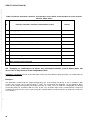
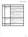
4.5.2
Evaluation of fault tolerance
Carry out evaluation of fault tolerance according to specific demands below by evaluation in detail design of
electronic hardware and software where applicable. Examples of faults and combination of faults for some different
design principles are evident from annex A, clause A.2 - A.3. Examples of applicable evaluation techniques are
listed in annex B.
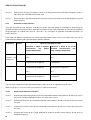
Fault modes for different components are evident from EN 61496-1:1997, annex B. Exclusions from this list are
evident from the following table (two alternative solutions allowed):
Component
Criteria
Limits for changing of values
Alternative 1: Work at nominal Alternative 2: Work at 2/3 of the
characteristics
(e.g.
power, maximum
characteristics
(e.g.
voltage, temperature)
power, voltage, temperature)
Safety
Resistors and
inductances
Capacitor
+100%,
+50%,
- 50%
-25%
Reliability
±
Tolerance
specified
manufacturer of component
by ± Tolerance specified by manufacturer
of component
Safety
+
Tolerance
specified
manufacturer of component
Tolerance
specified
by +
manufacturer of component.
- 50 %
Reliability
±
Tolerance
specified
manufacturer of component
by
-25%
by ± Tolerance specified by manufacturer
of component
The rest of the components in the table of EN 61496-1:1997, annex B are applicable only for safety.
NOTE The principle for 2/3 of the maximum characteristics is evident from EN 50020.
4.5.2.1
General fault tolerance evaluation
4.5.2.1.1
Evaluate for programming/testing units that unintended initiation (critical defects) do not occur even in
the presence of two independent faults in any parts of the system.
4.5.2.1.2
Evaluate for firing units that unintended initiation (critical defects) do not occur even in the presence of
one fault.
4.5.2.1.3
Evaluate that misfire of more than one detonator (major defects) do not occur even in the presence of
one fault.
4.5.2.1.4
Evaluate that misfire of one single detonator or incorrect function (minor defects) do not occur at
intended functioning.
18
CEN/TS 13763-27:2003 (E)
4.5.2.2
Specific fault tolerance evaluation
4.5.2.2.1
Evaluate that the non-firing of a series of detonators is impossible even in the presence of one fault.
4.5.2.2.2
Evaluate that the electronic components, which are necessary for safety and reliability, shall work at
the less than the nominal characteristics.
4.5.2.3 Fault tolerance evaluation - Incompatibility for use with conventional electric detonator systems
4.5.2.3.1
Evaluate that testing/programming unit for electronic initiation system is not capable of firing a
conventional electric detonator even in the presence of one fault in the testing/programming unit.
NOTE This requirement is fulfilled if the impulse or current level does not exceed the corresponding no-fire level
for the most sensitive electric detonator class (class I) even in the presence of one fault in the
testing/programming unit. If the no fire impulse is not exceeded the no fire current can be exceeded.
4.5.2.3.2
Evaluate that an electronic detonator even in the presence of one fault is not capable of being fired by
a testing unit for conventional electric detonators.
NOTE This requirement is fulfilled if the no fire current and no fire impulse of the electronic detonator fusehead is
higher than the maximum output current or impulse allowed of the testing unit for conventional electric detonators
in normal condition (i.e. no fault condition). The maximum output current and impulse for testing units for
conventional electric detonators is evident from prEN 13763-26.
4.5.3
Evaluation of design
Carry out evaluation according to specific demands below by evaluation in detail design of electronic hardware and
software where applicable. Examples of evaluation techniques are listed in annex B.
4.5.3.1
User interface
4.5.3.1.1
Evaluate that messages to the user firing/programming/testing units are presented in a way so that the
user clearly can understand the information.
4.5.3.1.2
Evaluate that if a planning tool (e.g. a computer program) is used, it shall be intuitive and the timing
information to the detonators shall be ordered in an unambiguous way to prevent errors as
connections in reverse order.
4.5.3.1.3
Evaluate that the operation of charge is obtained by a permanent positive command.
NOTE Further user interface demands indicated in 4.5.5.26 (reference to specified clauses of prEN 13763-26) shall also be
considered.
4.5.3.2
Software design and coding
This clause is valid only for software controlling the programming/testing/firing sequence.
4.5.3.2.1
Evaluate that the software is designed in a modular structure (see B.12). All modules shall also
contain the name of the programmer, the original date and revision.
4.5.3.2.2
Identify the safety critical variables and which procedures that use safety-critical variables and if they
are local or global. Evaluate that safety-critical variables are not used by non safety-critical procedures
(see B.13).
4.5.3.2.3
Evaluate that the possibility for executing wrong program parts are reduced to a minimum (see B.14)
19
CEN/TS 13763-27:2003 (E)
4.5.3.2.4
Evaluate that the software version is possible to read out, either on a display or on a label. All software
shall be marked, both embedded software and PC programs.
NOTE Further information about design, development and coding of software is evident from IEC 61508-3:1998, especially
clauses 7.4.5 Requirements for detailed design and development and Tables A.4, B.1, B.7 and B.9 as well as clause 7.4.6
Requirements for code implementation and Tables A.5, B.2, B.3 and B.6.
4.5.3.3 Transmission of information
4.5.3.3.1
For electronic initiation systems using digital code transmission (i.e. sending digital “words”), evaluate
that the transmission of information- and the integrity of the communication system are in conformity
with EN 60870-5-1 :
• level I1 if faulty information can affect the reliability of the shot,
• level I2 if faulty information can have a direct influence on the safety of persons and if the
detonators can be armed or initiated by the voltage used for communication. Otherwise, use level
I1.
For electronic initiation systems, which do not use digital code transmission, e.g. systems based on
coding information within specific time windows, the evaluation has to take the specific system into
account. This may be a change of time window length (add or reduce a typical length), a change from
high signal level to low signal level or in the other direction. The faults shall not change the information
to an unintended arming or firing signal.
If the system contains other systems than CRC (cyclic redundancy check) this shall be considered
when evaluating the safety of the system. In general for both transmission principles (with or without
digital coding) means to provide error detection and handling shall be included in the system.
4.5.3.4
Techniques to control random hardware failures in complex electronics
The detection, handling and indication of random hardware faults may be evaluated, for e.g, by:
• Fault simulation/Fault insertion testing (B.4).
• Walk-throughs/design reviews (B.7).
Evaluate that firing units and testing/programming units as well as detonators having two way data communication
include suitable self-checking possibilities during start-up. Safety of single bit errors shall be considered only. The
following protective measures shall be taken:
4.5.3.4.1
Checking of faults in variable memory storing safety-related data.
4.5.3.4.2
Checking of errors in non-variable memory storing program code or data.
4.5.3.4.3
Power supply monitoring to be able to halt the execution in a controlled way at supply power failure.
4.5.3.4.4
Checking of program flow e.g. by a watchdog function.
4.5.4
User manual
Evaluate that the following information according to 4.5.4.1 to 4.5.4.5 is evident from the user manual where
applicable:
4.5.4.1
User manual - Warning
4.5.4.1.1
Indicate that these electronic detonators are totally different to conventional electric detonators.
20
CEN/TS 13763-27:2003 (E)
4.5.4.1.2
Indicate that only people, who have been educated to use such a system, shall use the electronic
initiation system.
4.5.4.1.3
Specify that absolutely no connection with conventional electric detonators and with other electronic
detonators is possible. Clarify the consequence of a possible misuse in this respect.
4.5.4.1.4
Do not use other devices than those specially designed for this type of Electronic Detonators.
4.5.4.2
User manual - Description of detonators accessories and devices
4.5.4.2.1
Electronic detonator.
4.5.4.2.2
Programming unit (if one is used).
4.5.4.2.3
Testing unit (if one is used).
4.5.4.2.4
Firing unit.
4.5.4.2.5
Wires.
4.5.4.2.6
Connectors.
4.5.4.2.7
Other devices (e.g. computer).
4.5.4.2.8
Options.
4.5.4.3
User manual - Operations
4.5.4.3.1
List parts mandatory for use (including possible options).
4.5.4.3.2
State maximum quantities of electronic detonators and maximum length of line authorized for one
blast.
4.5.4.3.3
Summary and/or check list and/or synoptic of the complete procedure.
4.5.4.3.4
Handling and introduction of the electronic detonator in hole.
4.5.4.3.5
Programming of the detonators (if necessary).
4.5.4.3.6
Testing of the detonators (if necessary).
4.5.4.3.7
Connection of the detonators on the main line (how to do, cautions....).
4.5.4.3.8
Operation before initiation of the blast (check list).
4.5.4.3.9
Triggering of the blast (how and when to proceed).
4.5.4.4
User manual - Safety precautions and safety relevant data
4.5.4.4.1
4.5.4.4.2
Precautions during handling.
Precautions between each steps of the operations.
4.5.4.4.3
Safety against:
•
•
Stray current
Radio frequency radiation
•
Electrostatic discharge
21
CEN/TS 13763-27:2003 (E)
4.5.4.4.4
How to react in case of fault:
•
•
During programming
During testing
•
During operations before triggering the blast
4.5.4.4.5
How to proceed in case of misfire.
4.5.4.4.6
Material safety data sheet.
4.5.4.5
User manual - Performance characteristics
4.5.4.5.1
Delay accuracy.
4.5.4.5.2
4.5.4.5.3
Maximum delay time available and delay increment.
Maximum detonator quantities possible for one blast.
4.5.4.5.4
Maximum length for the line.
4.5.4.5.5
Maximum and minimum temperature for storage and for use.
4.5.4.5.6
Watertightness/hydrostatic pressure.
4.5.4.5.7
Output strength.
4.5.4.5.8
Shelf life.
4.5.4.5.9
Required connecting instructions if delay system is depending of the connection order.
NOTE If overlapping is possible between two consecutive delay intervals, this information should be provided to the user (see
4.5.6.3.5).
4.5.5
Test methods referring to standards for detonators, blasting
resistance meters
machines,
test
apparatus
and
Where applicable (depending on the risk estimation in 4.4), carry out testing according to the following standards
for detonators, blasting machines, test apparatus and resistance meters. Possible amendments and applicability
remarks shall be considered.
4.5.5.1 Requirements
The requirements to be applied to detonators and relays for civil uses when subjected to the test methods are
given in prEN 13763-1.
4.5.5.1.1
Applicability
The requirements indicated in the clauses of prEN 13763 -1 are applicable if the corresponding test method in
4.5.5.2 to 4.5.5.26 is applicable.
4.5.5.1.2
Amendments
No amendments are necessary.
4.5.5.2 Determination of thermal stability
The determination of thermal stability of detonators is given prEN 13763-2.
4.5.5.2.1
Applicability
The test method is directly applicable.
22
CEN/TS 13763-27:2003 (E)
4.5.5.2.2
Amendments
No amendments are necessary.
4.5.5.3
Determination of sensitiveness to impact
The determination of sensitiveness to impact is given in prEN 13763-3.
4.5.5.3.1
Applicability
The test method is directly applicable.
4.5.5.3.2
Amendments
Instead of original samples, equivalent samples without electronic parts can be used. In the case of parts which in
the influence by impact could cause an unintended initiation (like piezoelectric etc.), additional tests with impact on
these parts shall be carried out.
4.5.5.4 Determination of resistance to abrasion of leading wire and shock tube.
The determination of resistance to abrasion of leading wire and shock tube is given in prEN 13763-4.
4.5.5.4.1
Applicability
The test method is directly applicable.
4.5.5.4.2
Amendments
No amendments are necessary.
4.5.5.5 Determination of resistance to cutting damage of leading wire and shock tube.
The determination of resistance to cutting damage of leading wire and shock tube is given in prEN 13763-5.
4.5.5.5.1
Applicability
The test method is directly applicable.
4.5.5.5.2
Amendments
No amendments are necessary.
4.5.5.6 Determination of cracking in low temperatures of leading wire.
The determination of cracking in low temperatures of leading wire is given in prEN 13763-6.
4.5.5.6.1
Applicability
The test method is directly applicable.
4.5.5.6.2
Amendments
No amendments are necessary.
4.5.5.7 Determination of mechanical strength of leading wire, shock tube, connection, crimp and closure.
The determination of mechanical strength of leading wire, shock tube, connection, crimp and closure is given in
prEN 13763-7.
23
CEN/TS 13763-27:2003 (E)
4.5.5.7.1
Applicability
The test method is directly applicable.
4.5.5.7.2
Amendments
No amendments are necessary.
4.5.5.8 Determination of resistance to vibration of plain detonator.
The determination of resistance to vibration of plain detonator is given in prEN 13763-8.
4.5.5.8.1
Applicability
The test method is not applicable.
4.5.5.8.2
Amendments
No amendments are necessary.
4.5.5.9 Determination of resistance to bending of detonator.
The determination of resistance to bending of detonator is given in prEN 13763-9.
4.5.5.9.1
Applicability
The test method is directly applicable.
4.5.5.9.2
Amendments
No amendments are necessary.
4.5.5.10 Determination of resistance to torsion of sealing plug.
The determination of resistance to torsion of sealing plug is given in prEN 13763-10.
4.5.5.10.1
Applicability
The test method is directly applicable with slight modification.
4.5.5.10.2
Amendments
According to 5.1 of prEN 13763-10:2000 the connection to an ohmmeter can be omitted or replaced by a suitable
measuring device for the electronic detonator type under test.
4.5.5.11 Determination of drop resistance of detonators and relays.
The determination of drop resistance of detonators and relays is given in prEN 13763-11.
4.5.5.11.1
Applicability
The test method is directly applicable.
4.5.5.11.2
Amendments
No amendments are necessary.
4.5.5.12 Determination of resistance to hydrostatic pressure.
The determination of resistance to hydrostatic pressure is given in prEN 13763-12.
24
CEN/TS 13763-27:2003 (E)
4.5.5.12.1
Applicability
The test method is directly applicable.
4.5.5.12.2
Amendments
No amendments are necessary.
4.5.5.13 Determination of resistance of electric detonator against electrostatic discharge.
The determination of resistance of electric detonator against electrostatic discharge is given in prEN 13763-13.
4.5.5.13.1
Applicability
The test method is directly applicable.
4.5.5.13.2
Amendments
In addition to the method described in prEN 13763-13 an additional test series has to be carried out to verify the
stress level for loss of function (major defect) according to 4.5.6.5 (detonator function test) of this Technical
Specification.
NOTE The test method given in prEN 13763- 13 is targeted at avoiding the danger of unintended detonation. In the case of
electronic detonators the test sample can pass the test with this respect but the stress also can destroy inner parts of the
detonator which then will misfire when energised later on. The stress levels leading to unattended detonation and to loss of
function can be different but both should be determined by this test. The manufacturer can specify different classes in respect of
safety and functionality.
4.5.5.14 Determination of resistance of electric detonator against the influence of radio frequency
radiation.
The determination of resistance of electric detonator against the influence of radio frequency radiation is given in
prEN 13763-14.
4.5.5.14.1
Applicability
The test method is not applicable.
4.5.5.14.2
Amendments
No amendments are necessary.
4.5.5.15 Determination of equivalent initiating capability.
The determination of equivalent initiating capability is given in prEN 13763-15.
4.5.5.15.1
Applicability
The test method is directly applicable.
4.5.5.15.2
Amendments
No amendments are necessary.
4.5.5.16 Determination of delay accuracy.
The determination of delay accuracy is given in prEN 13763-16.
4.5.5.16.1
Applicability
The test method is not applicable.
25
CEN/TS 13763-27:2003 (E)
4.5.5.16.2
Amendments
No amendments are necessary.
4.5.5.17 Determination of no fire current of electric detonator.
The determination of no fire current of electric detonator is given in prEN 13763-17.
4.5.5.17.1
Applicability
The test method is applicable depending on design of the electronic detonator.
NOTE Non of the standards for electric detonators are directly applicable, because the definitions of the relevant electrical
characteristics will fail. However, the standards can be used as a guidance to evaluate the sensitivity against electrical
influences. The sensitivity against stray currents should be seen according to special input characteristics. Furthermore in
contrast to conventional detonators test item function can be destroyed (major defect) without detonation (critical defect). Also
the sensitivity against short time current pulses can be checked similarly.
4.5.5.17.2
Amendments
No amendments are necessary.
4.5.5.18 Determination of series firing current of electric detonator.
The determination of series firing current of electric detonator is given in prEN 13763-18.
4.5.5.18.1
Applicability
The test method is not applicable.
4.5.5.18.2
Amendments
No amendments are necessary.
4.5.5.19 Determination of firing pulse of electric detonator.
The determination of firing pulse of electric detonator is given in prEN 13763-19.
4.5.5.19.1
Applicability
See 4.5.5.17.1 above.
4.5.5.19.2
Amendments
No amendments are necessary.
4.5.5.20 Determination of total resistance of electric detonator.
The determination of total resistance of electric detonator is given in prEN 13763-20.
4.5.5.20.1
Applicability
The test method is not applicable.
4.5.5.20.2
Amendments
No amendments are necessary.
4.5.5.21 Determination of flash-over voltage of electric detonator.
The determination of flash-over voltage of electric detonator is given in prEN 13763-21.
26
CEN/TS 13763-27:2003 (E)
4.5.5.21.1
Applicability
The test method is directly applicable in respect of determination of the flash-over voltage values. However the
requirements are not applicable.
NOTE The upper requirement level is related to the maximum voltage which the wire system can be electrostatically charged to
during loading of boreholes. This requirement level can be relevant also to electronic detonators. The lower requirement level is
related to the actual working voltage of the electronic detonators, which normally is much lower than conventional electric
detonators. This lower requirement level is therefore not applicable.
4.5.5.21.2
Amendments
The results shall be used to evaluate the requirement in 4.5.1.2.6.
4.5.5.22 Determination of capacitance, insulation resistance and insulation breakdown of leading wire.
The determination of capacitance, insulation resistance and insulation breakdown of leading wire is given in prEN
13763-22.
4.5.5.22.1
Applicability
The test method is applicable depending on actual working voltage of the electronic detonators. However the
requirements are not applicable.
NOTE The requirements for wire capacitance and insulation breakdown level are related to the maximum energy and voltage
respectively, which the wire system can be electrostatically charged to during loading of boreholes. This requirement level can
be relevant also to electronic detonators.
4.5.5.22.2
Amendments
The results shall be used to evaluate the requirement in 4.5.1.2.6.
4.5.5.23 Determination of shock wave velocity of shock tube.
The determination of shock wave velocity of shock tube is given in prEN 13763-23.
4.5.5.23.1
Applicability
The test method is directly applicable.
NOTE The test method is directly applicable for electronic detonators with shock tubes. For these systems the shock wave
velocity of the shock tube can have significant influence on the specified delay accuracy.
4.5.5.23.2
Amendments
No amendments are necessary.
4.5.5.24 Determination of non-conductivity of shock tube.
The determination of non-conductivity of shock tube is given in prEN 13763-24.
4.5.5.24.1
Applicability
The test method is directly applicable.
NOTE The test method is directly applicable for electronic detonators with shock tubes.
4.5.5.24.2
Amendments
No amendments are necessary.
27
CEN/TS 13763-27:2003 (E)
4.5.5.25 Determination of transfer capacity of relay and coupling accessory
The determination of transfer capacity of relay and coupling accessory is given in prEN 13763-25.
4.5.5.25.1
Applicability
The test method is directly applicable.
NOTE The test method is directly applicable for electronic detonators with shock tubes if e.g. surface connectors are used.
4.5.5.25.2
Amendments
No amendments are necessary.
4.5.5.26 Definitions, methods and requirements for devices and accessories for reliable and safe function
of detonators and relays
The definitions, methods and requirements for devices and accessories for reliable and safe function of detonators
and relays are given in prEN 13763-26.
4.5.5.26.1
Applicability/Amendments
The following clauses of prEN 13763- 26 are applicable:
•
Clause 4 -Environmental tests. General description: The test methods are directly applicable without
amendments.
•
Clause 5 - Blasting machines for initiating electric detonators - Applicability for firing units.
•
•
Subclause 5.2 - Test for insulation resistance between exposed conducting parts: Requirements and
testing method are directly applicable without amendments.
•
Subclause 5.3 - Test for adequacy of insulation: If no high voltages are present, this test can be deleted;
the preceding test for insulation resistance with 500 V will be sufficient. If high voltages (approx. 100 V)
are present, the test can be applied without amendments.
•
Subclause 5.15 - Environmental tests for all blasting machines: Requirements and testing method are
directly applicable for firing units without amendments.
Clause 7 - Field circuit testers - Applicability for programming/testing units:
•
Subclause 7.1 - Requirements: Requirements are directly applicable without amendments.
•
Subclause 7.2 – Test for insulation resistance: Requirements and testing method are directly applicable
without amendments.
•
Subclause 7.3 – Test for electrical voltage withstand: If no high voltages are present, this test can be
deleted; the preceding test for insulation resistance with 500 V will be sufficient. If high voltages (approx.
60 V) are present, the test can be applied without amendments.
•
Subclause 7.7 - Environmental tests for field circuit testers: Requirements and testing method are directly
applicable without amendments.
NOTE The applicability of 5.2, 5.3, 7.2 and 7.3 should take into account different design principles if only low voltages are
present (< 60 V d.c.).
28
CEN/TS 13763-27:2003 (E)
4.5.6
Test methods specific for electronic initiation systems
Where applicable (depending on the risk estimation in 4.4), carry out testing according to the following. Possible
amendments and applicability remarks shall be considered.
4.5.6.1 Slow temperature change test
4.5.6.1.1
Introduction
During a storage time the detonators have to withstand many cycles changing the ambient temperature. This test is
an artificial ageing test to verify the reliability after a long storage time.
4.5.6.1.2
Test pieces
Test 30 complete electronic detonator assemblies, a special choice of delay numbers or delay times is not
required.
4.5.6.1.3
Apparatus
The apparatus shall comply with the requirements specified in IEC 60068-2-14. For this test a programmable
climatic chamber is needed.
4.5.6.1.4
Procedure
4.5.6.1.4.1
Initial check
Carry out an initial check of each electronic detonator using a testing unit for the current electronic initiation system.
4.5.6.1.4.2
Slow temperature change test
Perform temperature testing in accordance with IEC 60068-2-14, test Nb at test temperatures from –25 ° C up to
+70 ° C.
•
Test period t1 is set to 4 h
•
Transition time t2 is set to 8 h
•
Number of cycles is set to five.
NOTE That means, starting with the cold temperature, cooling down 4 h, stay 4 h at cold, heating up 8 h, stay 4 h, cooling down
8 h and so on for five cycles.
4.5.6.1.4.3
Performance test
After exposure carry out the “Detonator function test” according to 4.5.6.5 at a temperature of 20 °C ± 5 °C after
recovery treatment. Record the result of the “Detonator function test”.
4.5.6.1.5
Requirements
All tested detonators shall comply with the requirements of the “Detonator function test”, 4.5.6.5.
4.5.6.2
Rapid temperature change test
4.5.6.2.1
Introduction
The background of this test is the use of detonators in hot emulsions. When the borehole is filled with hot
emulsions the detonator will be exposed to a hot temperature shock and slow cooling down afterwards.
The exposure to frost happens, when the detonator is transported from a magazine to a frost environment at the
borehole.
29
CEN/TS 13763-27:2003 (E)
4.5.6.2.2
Test pieces
Test 20 complete electronic detonator assemblies, a special choice of delay numbers or delay times is not
required.
4.5.6.2.3
Apparatus
The apparatus shall comply with the requirements specified in IEC 60068-2-14.
4.5.6.2.4
Procedure
4.5.6.2.4.1
Initial check
Carry out an initial check of each electronic detonator, using a testing unit for the current electronic initiation
system.
4.5.6.2.4.2
Rapid temperature change test
Perform temperature testing in accordance with IEC 60068-2-14, test Na at test temperatures from –10 °C up to
+80 °C.
•
Test period t1 is set to 4 h, one cycle.
NOTE That means, starting with the cold temperature stay 4 h and then stay 4 h in the hot chamber.
4.5.6.2.4.3
Performance test
After exposure carry out the “Detonator function test” according to 4.5.6.5 at a temperature of 20 °C ± 5 °C after
recovery treatment. Record the result of the “Detonator function test”.
4.5.6.2.5
Requirements
All tested detonators shall comply with the requirements of the “Detonator function test”, 4.5.6.5.
4.5.6.3
4.5.6.3.1
Test method for the determination of delay accuracy of electronic detonators
Scope
The purpose of this method is to determine the delay accuracy of an electronic detonator. The method consists of
determining the delay accuracy of the electronic part (without pyrotechnic) and of the detonator.
NOTE For determining the delay accuracy of the electronic part, dummy detonator can be used. By dummy detonators, you
can understand detonators with only the electronic parts. The fusehead can be replaced by a LED or other device able to deliver
an adequate signal which can be detected by the measurement device (see annex C). For programmable detonator, the
electronic part can be reused for tests.
4.5.6.3.2
Test pieces
For programmable and non programmable detonators, test 20 detonators or 20 dummy detonators of each delay at
approximately 10%, 25%, 50%, 75% and 100% of the time scale specified by the manufacturer. If these tests are
made on dummy detonators, test, in addition, 20 complete detonators of each delay at approximately 25% and
75% of the time scale specified by the manufacturer.
For pre programmed detonators, test 20 detonators or 20 dummy detonators of each delay number specified by the
manufacturer. If these tests are made on dummy detonator, test, in addition, 20 complete detonators at
approximately 25% and 75% of the time scale specified by the manufacturer.
For all types of programmable electronic detonators test also 20 detonators each of two consecutive delay
numbers at approximately 25% and 75% of the time scale specified by the manufacturer to verify the risk of
overlapping is insignificant. These tests are conducted at ambient temperature.
30
CEN/TS 13763-27:2003 (E)
For all types of electronic detonators test also at the minimum and at the maximum temperature, specified by the
manufacturer, 20 detonators or dummy detonators at the longest delay time specified by the manufacturer.
4.5.6.3.3
Apparatus
•
Firing unit and/or programming unit and/or testing unit specified by the manufacturer shall only be used to
make the tests.
•
Timer or oscilloscope with the means to measure delay time between the start pulse and the stop pulse with an
accuracy of 0,01ms.
•
Mean to provide the start pulse can be either the signal given by the firing unit or a detonator with a zero delay
(according to manufacturer specification).
•
Means providing a stop pulse to the timer/oscilloscope can consist, for the tests with the complete detonator, of
an optical sensor or pressure sensor providing an electric pulse when the base charge of the detonator is
initiated, for tests with the dummy detonator, a sensor, according to the device use to replace the fusehead,
providing an electric pulse when such device simulate the initiation.
4.5.6.3.4
Procedure
4.5.6.3.4.1
General purpose
It is necessary to check the following characteristics:
- Time steps
- Accuracy
- Temperature dependency
These characteristics are to be tested on the detonator to check the full system and on dummy detonator to check
the electronic part (if possible).
4.5.6.3.4.2
Conditioning
Condition the detonators/dummy detonators for at least 2 h before testing at a temperature specified by the
manufacturer. For programmable and pre programmed electronic detonators, program the detonators/dummy
detonator before conditioning. Before conditioning, detonators/dummy detonators shall be checked with the
appropriate means according to manufacturer procedure.
4.5.6.3.4.3
Testing
Connect the detonator/dummy detonator to the firing unit, install the appropriate start pulse sensor/or the zero
detonator and the appropriate stop pulse sensor, initiate (according to manufacturer procedure) the
detonator/dummy detonator and record each individual delay time.
NOTE Firing tests at high and low temperature are made, if possible, in the conditioning device.
4.5.6.3.4.4
Expression of results
•
Calculate the mean value (tm) and the standard deviation (s) of each interval tested and determine the
accuracy of the system at ambient temperature.
•
Compare the results (tm and s) obtain at minimum, ambient and maximum temperature to determine the
temperature dependency.
•
If tests have been done on dummy detonators compare the results obtained between dummy and detonators to
calculate the time delay of the pyrotechnic parts.
31
CEN/TS 13763-27:2003 (E)
•
Compare these results to the manufacturer specification.
4.5.6.3.5
Requirements
Requirements are according to manufacturer specification. Calculate tm ± 3 s for each interval and check, according
to manufacturer specification.
In addition, check that the risk of overlapping between two consecutive delay intervals is insignificant by applying
the requirement in prEN 13763- 16. If overlapping is significant between two consecutive delay intervals, this
information shall be provided to the user (see 4.5.4.5).
These requirements are also applied to detonators after environmental testing.
4.5.6.4 Test method for the determination of electromagnetic compatibility of electronic detonators
4.5.6.4.1
Introduction
The purpose of this test is to verify that electronic initiation systems are safe and reliable when subjected to
electromagnetic radiation. The test is divided into two parts:
•
Testing with a high stress level in order to ensure that no unintended initiation occur.
•
Testing with a lower stress level in order to ensure the proper functioning of the system during stress.
4.5.6.4.2
Test pieces
For the tests described dummy detonators may be used if their high frequency behaviour can be assumed to be
equal to normal full strength detonators of the same type.
4.5.6.4.2.1
Safety against unintended initiation
Test up to 10 detonators from the electronic initiation system depending on the worst case conditions specified in
4.5.6.4.4.1 below.
4.5.6.4.2.2
Functioning during stress
Test 10 detonators from the electronic initiation system.
4.5.6.4.3
Apparatus
As specified in EN 61000-4-3 and EN 61000-4-6
4.5.6.4.4
4.5.6.4.4.1
Procedure
Safety against unintended initiation
For the tests described below, apply the worst case condition (or conditions) for the specific system as close to the
real field conditions as possible e.g:
-
Detonator(s) and wires (without any connection to a testing/programming unit).
-
Detonator(s) and wires connected to a testing/programming unit.
Consider also the worst condition regarding choice of:
-
Wire length.
-
Possible connection of detonators to earth.
Perform the following tests:
32
CEN/TS 13763-27:2003 (E)
•
Perform immunity to conducted disturbances, induced by radio-frequency fields test in accordance with EN
61000-4-6 with a voltage of 30 V at frequencies from 150 kHz - 80 MHz.
•
Perform radiated, radio-frequency, electromagnetic field immunity test in accordance with EN 61000-4-3 with a
field strength of 30 V/m at frequencies from 80 MHz – 1 GHz.
•
Perform radiated, radio-frequency, electromagnetic field immunity test in accordance with EN 61000-4-3 with a
field strength of 10 V/m at frequencies from 1 GHz – 2 GHz.
For each test record any initiation of the detonators.
4.5.6.4.4.2
Functioning during stress
For the tests described below connect the detonators to the firing unit. Apply the worst case condition for the
specific system as close to the real field conditions as possible regarding choice of:
-
Wire length.
-
Possible connection of detonators to earth.
Perform the following tests:
•
Perform immunity to conducted disturbances, induced by radio-frequency fields test in accordance with EN
61000-4-6 with a voltage of 10 V at frequencies from 150 kHz - 80 MHz. Select 30 discrete frequencies evenly
distributed in the frequency range each for which a complete initiation process including firing is carried out.
Additionally perform firing after completion of the test (i.e. without stress applied).
NOTE 1 The 10 V stress level can be severe and should be reviewed when experience from different systems has been
achieved.
•
Perform radiated, radio-frequency, electromagnetic field immunity test in accordance with EN 61000-4-3 with a
field strength of 10 V/m at frequencies from 80 MHz – 1 GHz. Select 10 discrete frequencies evenly distributed
in the frequency range each for which a complete initiation process including firing is carried out. Additionally
perform firing after completion of the test (i.e. without stress applied).
NOTE 2 The 10 V/m stress level can be severe and should be reviewed when experience from different systems has been
achieved.
•
Perform radiated, radio-frequency, electromagnetic field immunity test in accordance with EN 61000-4-3 with a
field strength of 3 V/m at frequencies from 1 GHz – 2 GHz. Select 10 discrete frequencies evenly distributed in
the frequency range each for which a complete initiation process including firing is carried out. Additionally
perform firing after completion of the test (i.e. without stress applied).
NOTE 3 The 3 V/m stress level can be severe and should be reviewed when experience from different systems has been
achieved.
For each test record any initiation of the detonators up to the time when the firing command is ordered. Record also
the proper firing of all detonators after giving the firing command.
4.5.6.4.5
4.5.6.4.5.1
•
Safety against unintended initiation
When tested in accordance with 4.5.6.4.4.1 no detonator shall be initiated.
4.5.6.4.5.2
•
Requirements
Functioning during stress
When tested in accordance with 4.5.6.4.4.2 no detonator shall be initiated until the firing command is ordered.
After giving the firing command all detonators shall be initiated.
33
CEN/TS 13763-27:2003 (E)
NOTE The stress levels can be severe and should be reviewed when experience from different systems has been achieved.
4.5.6.5
Detonator function test
4.5.6.5.1 Introduction
This test is only carried out after other tests specified in this Technical Specification. The purpose of this test is to
determine the proper firing function of the detonator.
4.5.6.5.2
Test pieces
Test the number of detonators as specified in the relevant clause of this Technical Specification.
4.5.6.5.3
Apparatus
The original specific firing equipment from the manufacturer, which is necessary to make a proper blast application.
For the delay time measurement a start trigger and firing detector and a time counter is necessary. In case of
dummy detonators also an oscilloscope, a probe head with isolated amplifier is needed. A time counter is needed if
the oscilloscope cannot measure the full time scale.
4.5.6.5.4
Procedure
Make sure, that the firing equipment is on well working conditions. Connect all detonators to firing equipment. Fire
the detonators and record the proper firing. In case of the dummy detonators, the firing pulse has to be measured
in quantity. The power of the generated firing pulse has to be minimum the all-fire condition of the specific qualified
ignition element. This can be verified by a scope measurement of the graph of the firing pulse on a dummy load, if
necessary with an isolated amplifier. When the dummy detonator generates a firing pulse after the firing order with
the all-fire conditions, the function of the detonator is okay.
4.5.6.5.5
Requirements
All detonators shall fire.
4.5.6.6
System function test
4.5.6.6.1
Introduction
The purpose of this test is to determine the proper operation and ignition of the detonators connected to the firing
device with the specified wire length of the firing line defined by manufacturer.
4.5.6.6.2
Test pieces
Alternative 1: One original ignition device and maximum volume of detonators defined by the manufacturer or
corresponding dummy detonators. However if dummy detonators are used, at least 10 complete detonators have to
be used at the end of the bus line (or similar most severe place in the round).
Alternative 2: One original ignition device, an equivalent simulating network representing the presence and the
complete function of detonators and at least 10 complete detonators at the end of the bus line (or similar most
severe place in the round), in order to simulate the maximum number of detonators defined by the manufacturer.
For both alternatives, dummy detonators (if used) shall principally be designed according to annex C, example 4 to
6, in order to simulate the function and characteristics of the fusehead properly.
34
CEN/TS 13763-27:2003 (E)
4.5.6.6.3
Apparatus
•
Original firing unit charged up, firing line or firing line impedance load specified by the manufacturer and the
number of detonators described above.
•
Apparatus according to 4.5.6.3.3 above (delay accuracy test).
4.5.6.6.4
Procedure
Use a firing device with enough charge, the quantity of detonators as described above, connected to the ignition
device with the firing line as described above. The detonators have to be connected with the specified tools by the
manufacturer. Fire the longest delay time specified by manufacturer. In case of using dummy detonators, the all-fire
condition has to be verified. Make sure, that the detonators before every test are in the reset state, like the start
condition before a real blast. Verify the last 10 detonators in the bus line (or similar most severe place in the round)
in respect of delay accuracy.
4.5.6.6.5
Requirements
All detonators shall fire. In addition for the 10 detonators at the end of the bus line (or similar most severe place in
the round), the requirements according to 4.5.6.3.5 (delay accuracy) shall be fulfilled.
4.6
Risk reduction (step 6 of Figure 4)
If the risk is reduced appropriately, proceed to 4.7.
NOTE If any risk is judged unacceptable, it should be reduced to acceptable levels by appropriate means in a staged process:
a) direct safety means (design);
b) descriptive safety means, e.g. restricting application, lifetime or environment;
c) redefining the intended use;
d) applying control measures.
4.7
Generation of other hazards (step 7 of Figure 4)
Determine whether the risk reduction procedure has introduced new hazards.
4.8
Evaluation of all identified hazards (step 8 of Figure 4)
If risks have been estimated for all identified hazards and the levels of acceptability are not exceeded proceed to
4.9, if not, return to 4.4.
4.9
Revised hazard identification (step 9 of Figure 4)
Verify that all hazards are identified. In that case the risk analysis, evaluation and testing procedure is completed. If
not, return to 4.3.
35
CEN/TS 13763-27:2003 (E)
5
Test report
The test report shall conform to EN ISO/IEC 17025. In addition, the following information shall be given:
• (a) results of the risk analysis, risk evaluation and testing procedure.
• (b) a list of possible hazards as defined in 4.3.
6
Requirements
All the requirements of each evaluation and test method according to the risk analysis procedure, clause 4 shall be
fulfilled.
36
CEN/TS 13763-27:2003 (E)
Annex A
(informative)
Examples of hazards and faults
A.1
Examples of hazards, hazardous situations and hazardous events as well as contributing
factors associated with electronic initiation systems.
The lists below are intended to provide an aide-memoire in identifying possible hazards associated with electronic
initiation systems under 4.3 of the risk analysis procedure.
General causes of hazards, hazardous situations and hazardous events
The causes of hazards, hazardous situations and hazardous events can be classified in the following categories:
• Electric environment (conducted interference, radiated interference)
E
• Climatic stress (high and low temperature, moisture)
Cl
• Mechanical stress (vibrations, shocks, impacts)
M
• Hardware Design fault
HD
• Hardware Stochastic fault
HS
• Software fault
S
• User fault
U
• Compatibility fault
Co
The tables below list examples of individual hazards. In some cases two or more hazards are necessary to cause
a defect. Other hazards not listed in the table may also be valid for certain systems. Some of the listed hazards
may not be valid for certain systems.
37
CEN/TS 13763-27:2003 (E)
Table A.1-Hazards, hazardous situations and hazardous events which could contribute to cause
unintended initiation - Critical defect
Nº
1.1
Hazards, hazardous situations and hazardous events
Causes
Unintended initiation during instrument check
- Current/energy/voltage derived from testing/programming unit through HD, HS, S, Co
integrated command circuit with sufficient level to fire
- Initiation command sent from testing unit/programming unit
HD, HS, S
- Detonator connected to testing unit for electric detonators
Co, U
- Detonator connected to other electrical energy source
Co, U
- Testing unit/programming unit connected to conventional electric Co, U
detonator
1.2
1.3
Unintended initiation after interrupted firing sequence
- Discharge command not received by detonator
S
- Energy source in detonator not discharged
HD, HS, S
- Discharge circuit not available (e.g. transistor or resistor)
HD, HS
Unintended fusehead initiation
- No connection of the fusehead pin to an energy source (e.g. power line, HD, HS
power capacitor)
1.4
1.5
38
Unintended primary/base charge initiation
- Mechanical influence
M
- Thermal influence
Cl
Unintended complete detonator initiation
- Electromagnetic influence
E
- Electrostatic influence
E
- Stray currents
E
CEN/TS 13763-27:2003 (E)
Table A.2-Hazards, hazardous situations and hazardous events which could contribute to cause misfire Major defect
Nº
2.1
2.2
2.3
2.4
2.5
Hazards, hazardous situations and hazardous events
Causes
Energy generation failure
- No energy sent to detonator/received by detonator
HD, HS, S
- Insufficient energy sent to detonator/received by detonator
HD, HS
Set-up or programming failure
- No set-up sent to detonator/received by detonator
S, E
- Incorrect set-up sent to detonator/received by detonator
S, E
Energy storing failure
- Undesired leakage of detonator energy source
HD, HS
- No or insufficient energy storing capacity
HD, HS
Initiation failure
- No initiation pulse sent to detonator/received by detonator
HD, HS, S, E
- Incorrect initiation pulse sent to detonator/received by detonator
E, S
- Energy not transferred to fusehead
HD, HS, S
- Delay timer does not count
HD, HS, S, M
- Primary/base charge does not ignite
HD, HS
Communication failure
- Communication blocked
HD, HS, S
- Communication interfered
E, S
39
CEN/TS 13763-27:2003 (E)
Table A.3-Hazards, hazardous situations and hazardous events which could contribute to cause incorrect
function - Minor defect
Nº
3.1
3.2
Hazards, hazardous situations and hazardous events
Causes
Set-up (programming failure)
- Incorrect delay sent to detonator/received by detonator
E, S
- Delay stored incorrectly
HD, HS, S
- Incorrect timing calibration (programming unit)
HD, HS, S
Delay execution failure
- Timer calibration failure of detonator
HD, HS, E, S
- Instability of timer
HD, HS, E, S, M
- Insufficient energy transferred to fusehead
HD, HS, E, S
3.3
Incorrect firing sequence order
E, S, U
3.4
Wire communication interfered
E, S
A.2 Examples of combinations to obtain that unintended initiation (critical defect) does not
occur even in the presence of two independent faults.
Guidelines - Examples of faults and combination of faults for some different design principles are evident from the
following list:
Example 1:
The detonator is powered by the programming/testing unit. If the limiting resistor Rp is not in accordance with
st
4.5.2.2.2 this resistor can be short-circuited (1 fault). The fusehead of the detonator can be ignited by direct
nd
contact to the programming/testing unit output terminals (2 fault). Then to avoid this configuration the limiting
resistor Rp shall be in accordance with 4.5.2.2.2. In that case all unique short circuits cannot initiate the fusehead.
To initiate the fusehead, it is necessary to charge the capacitor before and discharge the capacitor in the fusehead,
see example 2.
40
CEN/TS 13763-27:2003 (E)
Key
1 Programming Unit
2 Detonators
3 Charge
4 Blast
5 Discharge
Figure A.1 - Principle of programming unit and electronic detonator
NOTE A safety margin should be also applied on the output current value defined by this resistor. The safety margin between
output current of programming/testing unit in normal operation and the no-fire current of the fusehead (safety margin: 10 times,
to be co-ordinated with conventional electric detonators).
Example 2:
This detonator circuits are composed by one microcontroller, one firing capacitor, one discharge resistor, one
fusehead and three switches (one to charge the firing capacitor, one to discharge the firing capacitor and one to
initiate the fusehead). These switches are order by the microcontroller.
41
CEN/TS 13763-27:2003 (E)
Key
1
2
Communication line
Charge
3
4
Blast
Charge capacitor
5
6
Discharge
Discharge resistor
7
Fusehead
Figure A.2 - Principle of electronic detonator
Hypothesis
•
The software of programming unit/testing unit is not capable of sending charge order or fire order (”Digital
word” not included anywhere in the software code).
•
Each order received cannot be executed before the whole sequence has been checked.
Analysis of the circuits
To generate an unintended firing the following sequence should happen. Opening of discharge switch, closing of
charge switch and after few moment of charge closing of blast switch. This sequence needs default of three
components, then this detonator circuit is Tolerant of two faults.
Conclusion
•
To avoid an unintended firing, it is possible to use three independent circuits: the discharge circuit, the charge
circuit and the blast circuit. These three circuits should be independent as far as the software code.
•
To avoid an unintended charge and an unintended firing, it is possible to keep the discharge switch on, until the
charging phase.
A.3
Examples of reliability aspects for electronic initiation systems
Guidelines - Examples of some different design principles and possibilities to reach sufficient reliability levels are
evident from the following table:
42
CEN/TS 13763-27:2003 (E)
Example
Nº:
Design principle
Reliability criteria
1
Programmable
a) Voltage check on the bus AND
detonators using two
way
data b) The group of electronic detonators connected to the
communication
firing circuit can be interrogated and identified e.g. by
repeated message or checksum, to check the program
delay time and also the integrity (completeness) of the
shotfiring circuits. AND
c) The functioning of each microprocessor can be verified
before the charging of the shotfiring capacitors begins.
When the verification is positive, the microprocessor is
reputed to be safe, as long as its power supply is not
interrupted. AND
d) The blast order cannot be sent if all detonator has not
received the necessary energy for the blast.
NOTE
Reliability can be increased by verifying every critical
parts of the detonators in order to firing as intended( e.g. fusehead,
charge level …)
2
Programmable
a) A complete function test of programming, charging
detonators using one and firing order at production of the electronic parts in
way
data order to ensure that all produced detonators are
communication
functioning AND
b) Verification that all detonators are connected by
measuring
NOTE
Reliability can be increased by checking signal quality (e.g.
by feedback from the end of the bus)
3
Programmable
See reliability criteria of programmable detonators using one
detonators using no way communication
data communication
43
CEN/TS 13763-27:2003 (E)
Annex B
(informative)
Information on evaluation techniques
B.1
General
The fault-tolerance of the system can be evaluated e.g. by the methods indicated in B.2 to B.4 below. The
functionality of the system can be evaluated e.g. by the methods indicated in B.5 to B.14 below.
The standards referred to are:
•
IEC 60812 – Analysis techniques for system reliability – Procedure for failure mode and effects analysis
(FMEA)
•
IEC 61025 – Fault tree analysis (FTA)
•
IEC 61508-7 - Functional safety of electrical/electronic/programmable safety-related systems - Part 7:
Overview of techniques and measures
•
EN 60870-5-1 Telecontrol equipment and systems – Part 5: Transmission protocols – Section 1: Transmission
frame formats (IEC 60870-5-1:1990)
B.2
Failure Mode and Effects Analysis (FMEA)
•
IEC 60812.
•
IEC 61508-7
B.3
Fault Tree Analysis (FTA)
•
IEC 61025
•
IEC 61508-7
B.4
•
B.5
•
B.6
•
B.7
•
B.8
•
44
B.6.6.1
B.6.6.5
Fault simulation/Fault insertion testing
IEC 61508-7
B.6.10
Functional testing
IEC 61508-7, B.5.1
Black box testing
IEC 61508-7, B.5.2
Walk-throughs/design reviews
IEC 61508-7, C.5.16
Boundary value analysis
IEC 61508-7, C.5.4
CEN/TS 13763-27:2003 (E)
B.9
•
Control flow analysis
IEC 61508-7, C.5.9
B.10
•
IEC 61508-7, C.5.10
B.11
•
Avalanche/stress testing
IEC 61508-7, C.5.21
B.12
•
Data flow analysis
Modular structure
IEC 61508-7,
C.2.7 Structured programming
C.2.9 Modular approach
B.13
•
IEC 61508-7, C.2.8 Information hiding / encapsulation
B.14
•
Use of safety critical variables
Wrong parts of program
IEC 61508-7,
C.2.6.5 Limited use of interrupts
C.2.6.6 Limited use of pointers
C 2.6.7 Limited use of recursion
B.15
Transmission of information
EN 60870-5-1
45
CEN/TS 13763-27:2003 (E)
Annex C
(informative)
Proposals for the detonator fusehead replaced (dummy detonators)
The common characteristics of electronic detonators are some operating wires leading into the shell to the
electronic part and somewhere minimum exist two contacts for the initiating part, like a fusehead or a similar
device. For an electronic function test it is useful to have the fusehead replaced by an optical light emitting device
like a LED (Light Emitting Diode), a bulb, magnetic coil, shunt arrangement to measure the firing pulse,
combination of resistance replacement and magnetic coil for the firing pulse measurement or a replaceable
fusehead to detect the firing pulse. If it is necessary the shell can be sealed with silicone rubber at the end of the
replaced device. For the electronic it is harder to do the test without sealing.
Key
1
LED
Figure C.1 - Example for a LED replacement
Key
1
Bulb
Figure C.2- Example for a bulb replacement
Key
1
Magnetic coil
Figure C.3- Example for a magnetic coil replacement
46
CEN/TS 13763-27:2003 (E)
Key
1
Resistor
2
Current shunt
Figure C.4- Example for a shunt arrangement
Key
1
2
Resistor
Magnetic coil
Figure C.5- Example for a combination of resistor replacement and magnetic coil
Key
1
Fusehead
Figure C.6- Example for a replaceable fusehead
47
CEN/TS 13763-27:2003 (E)
Annex D
(informative)
Determination of resistance to dynamic pressure
In blasting applications delay detonators are subjected to dynamic pressure due to the detonation of adjacent
boreholes. For conventional delay detonators the pyrotechnic delay charge can already be initiated at the moment
of detonation of an adjacent borehole. The pyrotechnic delay charge is normally protected inside a delay element,
which increases the resistance of the detonator against the influence of dynamic pressure.
However for electronic detonators the delay time is controlled by the electronics inside the detonator, which may,
depending on design, cause the detonator to be significantly sensitive to dynamic pressure. For proper functioning
it is therefore required that the electronics inside the detonator is not damaged due to the detonation of an adjacent
borehole.
Since no standardized test method for determination of resistance to dynamic pressure exists at the moment, this
aspect has not been covered by this Technical Specification. Further R&D work is required to develop a test
method.
However, even in the lack of a test method, proper measures should be taken in order to ensure that the electronic
detonator is sufficiently resistant to dynamic pressure.
48
CEN/TS 13763-27:2003 (E)
Bibliography
EN 50020; Electrical apparatus for potentially explosive atmospheres - Intrinsic safety "i".
IEC 60812; Analysis techniques for system reliability – Procedure for failure mode and effects analysis (FMEA)
IEC 61025; Fault tree analysis (FTA)
IEC 61508-3:1998; Functional safety of electrical/electronic/programmable electronic safety-related systems —
Part 3: Software requirements.
IEC 61508-7; Functional safety of electrical/electronic/programmable electronic safety-related systems — Part 7:
Overview of techniques and measures.
49
DD CEN/TS
13763-27:2003
BSI — British Standards Institution
BSI is the independent national body responsible for preparing
British Standards. It presents the UK view on standards in Europe and at the
international level. It is incorporated by Royal Charter.
Revisions
British Standards are updated by amendment or revision. Users of
British Standards should make sure that they possess the latest amendments or
editions.
It is the constant aim of BSI to improve the quality of our products and services.
We would be grateful if anyone finding an inaccuracy or ambiguity while using
this British Standard would inform the Secretary of the technical committee
responsible, the identity of which can be found on the inside front cover.
Tel: +44 (0)20 8996 9000. Fax: +44 (0)20 8996 7400.
BSI offers members an individual updating service called PLUS which ensures
that subscribers automatically receive the latest editions of standards.
Buying standards
Orders for all BSI, international and foreign standards publications should be
addressed to Customer Services. Tel: +44 (0)20 8996 9001.
Fax: +44 (0)20 8996 7001. Email: [email protected]. Standards are also
available from the BSI website at http://www.bsi-global.com.
In response to orders for international standards, it is BSI policy to supply the
BSI implementation of those that have been published as British Standards,
unless otherwise requested.
Information on standards
BSI provides a wide range of information on national, European and
international standards through its Library and its Technical Help to Exporters
Service. Various BSI electronic information services are also available which give
details on all its products and services. Contact the Information Centre.
Tel: +44 (0)20 8996 7111. Fax: +44 (0)20 8996 7048. Email: [email protected].
Subscribing members of BSI are kept up to date with standards developments
and receive substantial discounts on the purchase price of standards. For details
of these and other benefits contact Membership Administration.
Tel: +44 (0)20 8996 7002. Fax: +44 (0)20 8996 7001.
Email: [email protected].
Information regarding online access to British Standards via British Standards
Online can be found at http://www.bsi-global.com/bsonline.
Further information about BSI is available on the BSI website at
http://www.bsi-global.com.
Copyright
Copyright subsists in all BSI publications. BSI also holds the copyright, in the
UK, of the publications of the international standardization bodies. Except as
permitted under the Copyright, Designs and Patents Act 1988 no extract may be
reproduced, stored in a retrieval system or transmitted in any form or by any
means – electronic, photocopying, recording or otherwise – without prior written
permission from BSI.
BSI
389 Chiswick High Road
London
W4 4AL
This does not preclude the free use, in the course of implementing the standard,
of necessary details such as symbols, and size, type or grade designations. If these
details are to be used for any other purpose than implementation then the prior
written permission of BSI must be obtained.
Details and advice can be obtained from the Copyright & Licensing Manager.
Tel: +44 (0)20 8996 7070. Fax: +44 (0)20 8996 7553.
Email: [email protected].